june 2005. for mnrf symposium 7 june 2005 ntd developments overview presented by: colin jacka 7 june...
TRANSCRIPT

June 2005
For MNRF Symposium 7 June 2005
NTD Developments Overview
Presented by: Colin Jacka7 June 2005
www.atnf.csiro.auRequirements from MNRF Grant
Stated aims at 2002 MNRF initiation: To develop multi-beaming antenna technology
Advanced optical signal transport
Advanced signal processing schemes
Developing interference mitigation techniques
Integrated into an operating instrument which would benefit the development path towards the SKA
Would make use of project deliverables from other MNRF-funded projects eg CABB, MMIC, SKA Siting
www.atnf.csiro.auMNRF Progress to date
Original NTD Project Plan Choose NTD concept by 30 June 2004
From that point on, the effort has been on FPAs using parabolic dish antennas
• Revised Preliminary NTD Project Plan 30 September 2004
• Roadmap towards SKA maximising Australia’s participation• NTD providing prototyping and design for xNTD, because
• xNTD could be a typical SKA station
www.atnf.csiro.auSKA Roadmap: The route forward
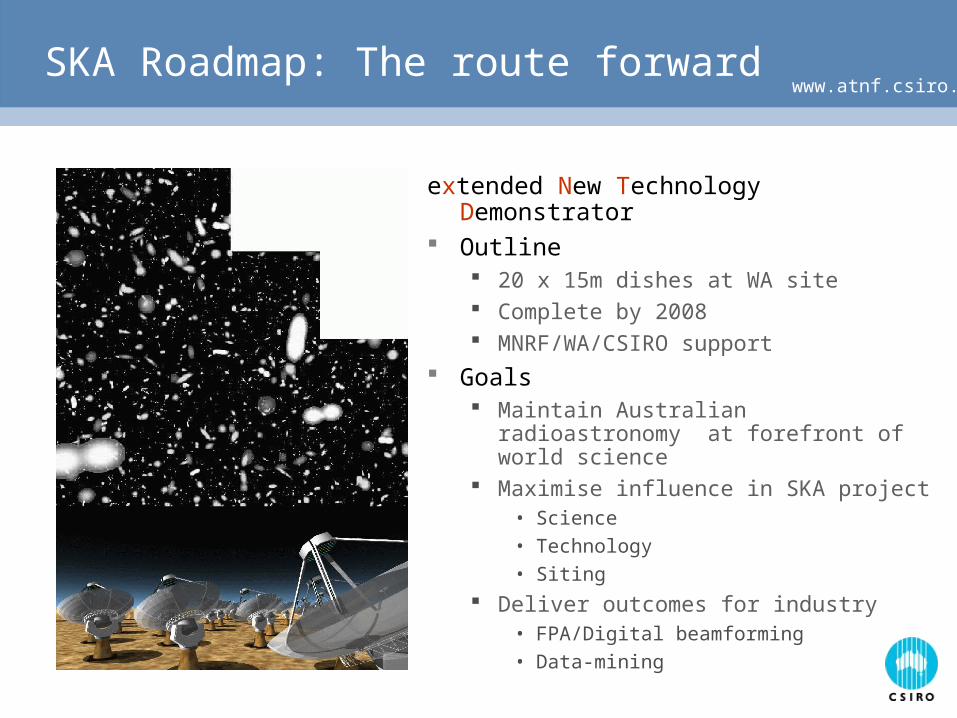
extended New Technology Demonstrator Outline
20 x 15m dishes at WA site Complete by 2008 MNRF/WA/CSIRO support
Goals Maintain Australian radioastronomy at
forefront of world science Maximise influence in SKA project
• Science
• Technology
• Siting
Deliver outcomes for industry• FPA/Digital beamforming
• Data-mining
www.atnf.csiro.auNTD and xNTD - Proposals
extended New Technology Demonstrator
Objectives: Key item in the strategy of maximising Australia’s
participation in the SKA (objective in CSIRO’s 2003-2006 Strategic Plan, and ATNF’s SKA Roadmap)
To build a new world-class radiotelescope at the Australian SKA site
• Telescope in its own right, with a lifetime of 5+ years, operated by ATNF as a National Facility
• But also a prototype for the SKA
• Risk mitigation for the International SKA Pathfinder (ISKAP), and leveraging of international funds
www.atnf.csiro.auWhat difference does the x make?
NTD
Funded by existing, secured ATNF + MNRF funds
2 interconnected dishes, 15m diameter, each with focal plane array, at proposed SKA site
xNTD
Additional funding from CSIRO, ATNF, WA State Gov, (and still soliciting others)
20 dishes, 15 m diameter, arranged in one group, genuine micro-SKA, at proposed SKA site
Project Plan: Design & Development Program until early 2006 is common for NTD and xNTD
xNTD implementation phase from Jan 2006, as a result of sufficient risk mitigation in areas of antenna, FPA, digital beamforming and correlator design
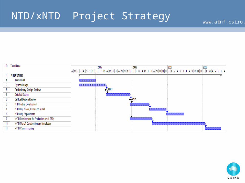
www.atnf.csiro.auNTD/xNTD Project Strategy
www.atnf.csiro.auChallenges for xNTD
List of (technology) challenges that we keep in mind, and note that NTD should allow us to tackle some of them: Can we make small steerable dishes cheap enough? Cheap, high performance (wide band and polarization pure) FPAs? Cheap, high performance integrated RXs? No self-generated RFI from RXs (or rejection schemes)? How to transport signals from FPA? DBF (efficient, cost-effective using FPGAs)? Calibration with synthesized varying beam patterns? Correlator (a very large effort) Data storage & transportation Remote operation as a NF from East Coast of Oz?
But also we note that: Many other large projects currently on-going Shortage of key people
www.atnf.csiro.auSo, where are we now?
(time marches on, but) we have made substantial progress in a number of areas
Antennas for NTD
RXs for NTD
FPA for NTD
Digital H/W for NTD beamformer and design of xNTD correlator
Interferometer experiment @ Marsfield
www.atnf.csiro.auNTD Antenna System
Presently looking at 3 alternatives to meet the challenge of performance/cost1. The Indian PPD dish design
2. New design using manufacturing techniques available in Australia
3. Refurbishing 2 antennas from Fleurs (for NTD)
All are on-going investigations for xNTD purposes, but for the NTD we are going with the ex-Fleurs antennas
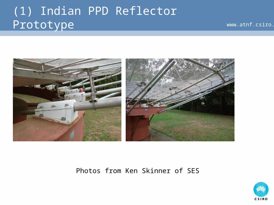
www.atnf.csiro.au(1) Indian PPD Reflector Prototype
Photos from Ken Skinner of SES
www.atnf.csiro.au(2) Reflector antenna options
Custom-built mesh reflector using NC machine tools “High-tech” solution with high accuracy, good repeatability, and no
tooling-up costs
Local manufacture of prefabricated “flat-pack” reflector; assemble on site
Progress: Engineering consultants have been contacted to provide structural
engineering analysis and comments on proposal
Manufacturers asked to comment on manufacturability issues of our design
Bristow Laser Systems have demonstrated new CNC machinery which appear to be ideal for manufacture
Advice being sought for patenting suitability of manufacturing methods
www.atnf.csiro.au(1) Reflector antenna options
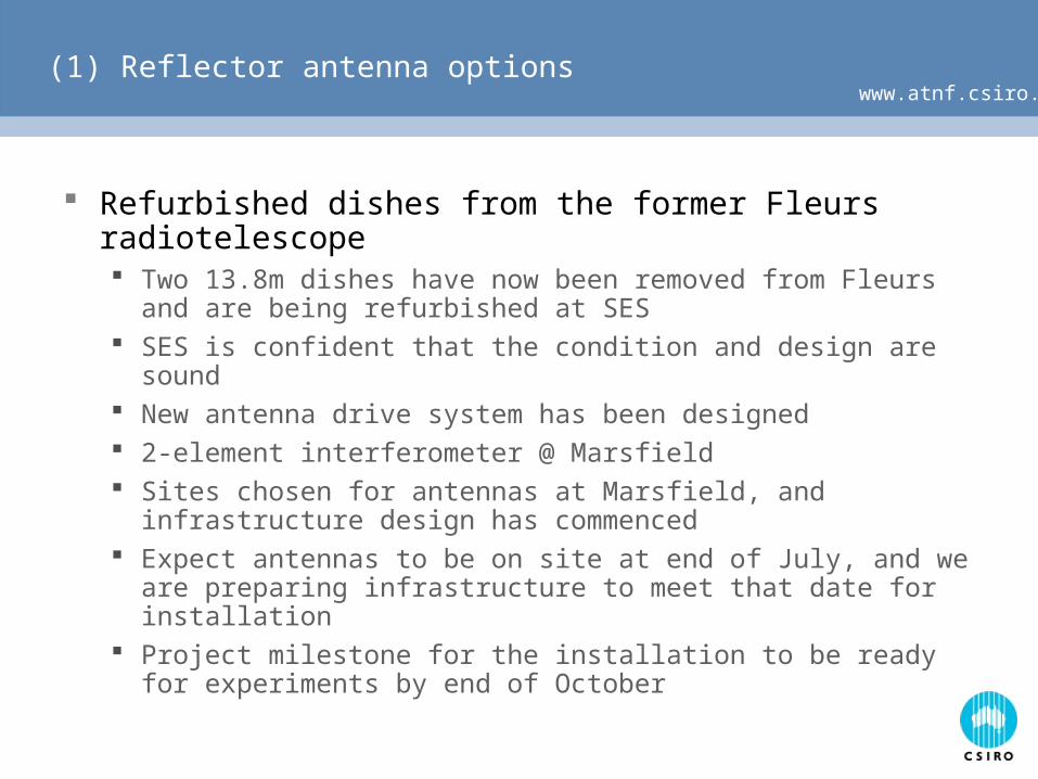
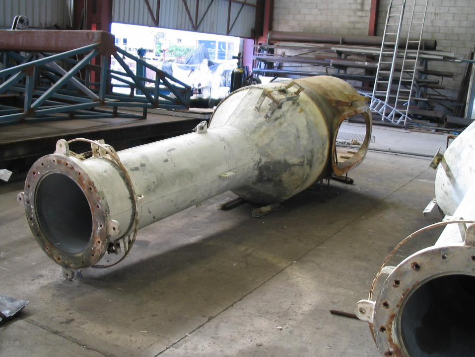
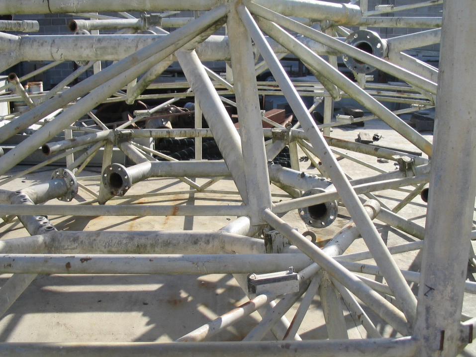
Refurbished dishes from the former Fleurs radiotelescope Two 13.8m dishes have now been removed from Fleurs and are
being refurbished at SES SES is confident that the condition and design are sound New antenna drive system has been designed 2-element interferometer @ Marsfield Sites chosen for antennas at Marsfield, and infrastructure design
has commenced Expect antennas to be on site at end of July, and we are
preparing infrastructure to meet that date for installation Project milestone for the installation to be ready for experiments
by end of October
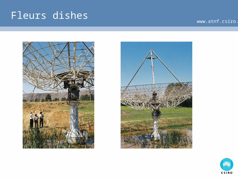
www.atnf.csiro.auFleurs dishes
www.atnf.csiro.au
www.atnf.csiro.au
www.atnf.csiro.au
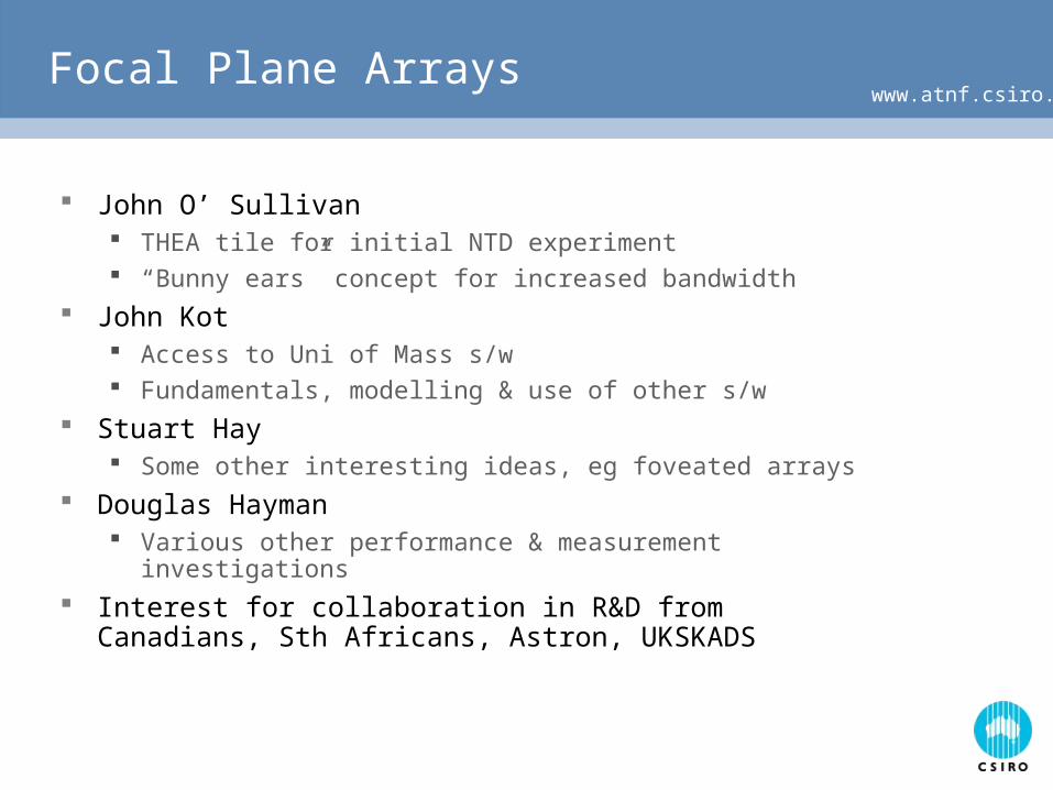
www.atnf.csiro.auFocal Plane Arrays
John O’ Sullivan THEA tile for initial NTD experiment “Bunny ears” concept for increased bandwidth
John Kot Access to Uni of Mass s/w Fundamentals, modelling & use of other s/w
Stuart Hay Some other interesting ideas, eg foveated arrays
Douglas Hayman Various other performance & measurement investigations
Interest for collaboration in R&D from Canadians, Sth Africans, Astron, UKSKADS
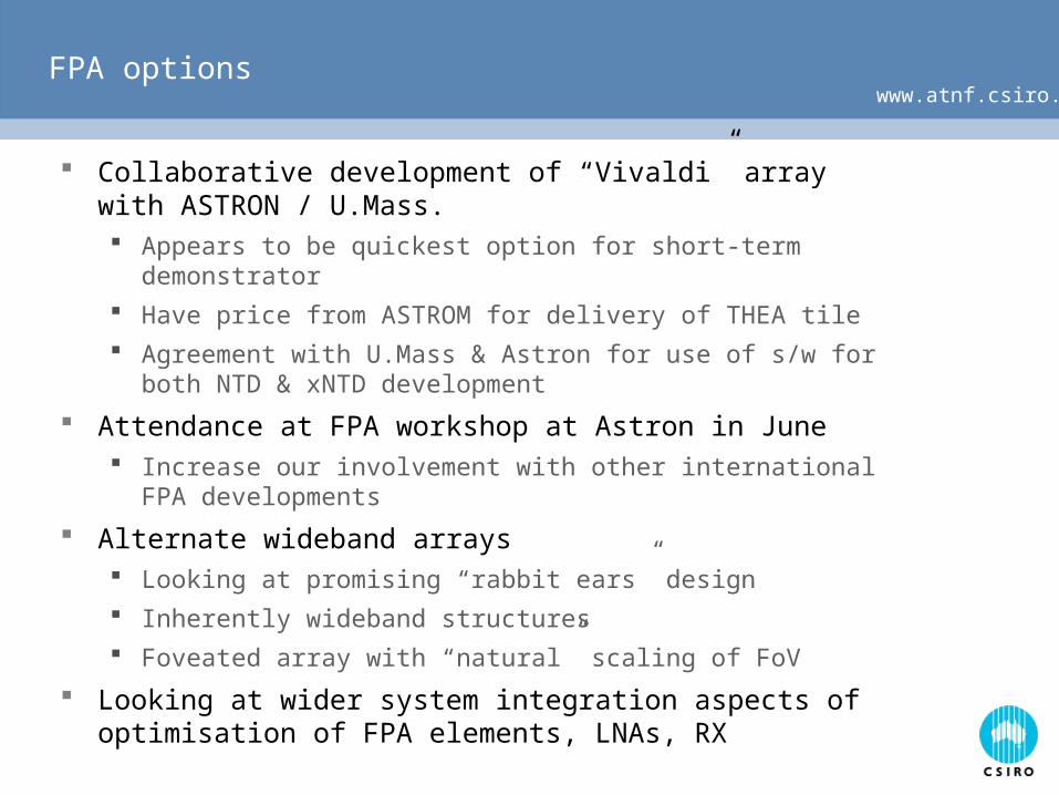
www.atnf.csiro.auFPA options
Collaborative development of “Vivaldi” array with ASTRON / U.Mass. Appears to be quickest option for short-term demonstrator
Have price from ASTROM for delivery of THEA tile
Agreement with U.Mass & Astron for use of s/w for both NTD & xNTD development
Attendance at FPA workshop at Astron in June Increase our involvement with other international FPA
developments
Alternate wideband arrays Looking at promising “rabbit ears” design
Inherently wideband structures
Foveated array with “natural” scaling of FoV
Looking at wider system integration aspects of optimisation of FPA elements, LNAs, RX
www.atnf.csiro.auReceiver
(200 RXs per dish equipped with FPA)
Prototype receiver design has been completed, development and testing
Some modifications discussed for use at “congested radio spectrum” at Marsfield
Separate LNA for Tsys requirements: being undertaken
www.atnf.csiro.auDigital Signal Processing
Designs have been refined such that they can efficiently handle:1. A 20-antenna xNTD using 10x10 element dual polarisation FPAs
2. A 500-antenna LFD (MIT Haystack) @ Mileura
3. A SKAMP-3 with 96 antennas
4. An LFD with only 48 antennas (LFD fallback @ Mileura)
All require a correlator NTD, xNTD and SKAMP require a digital beamformer for each
antenna While LFD requires a digital receiver Whitepaper shows commonality in the NTD beamformer and the
LFD RX Sth Africans also interested, but assessing other options as well
www.atnf.csiro.auDigital Signal Processing
Digital Beamformer design: one for each polarization on each antenna
• A considerable amount of h/w required to meet xNTD specs, but NTD is being used to mitigate risks,
• should only build h/w where it has value (rather than simulation, theory, paper designs), eg need inputs from all RXs for FPA analysis, but we don’t really need to have 48 beams on NTD. So NTD beamformer to have less beams.
Prototype NTD beamformer has 24 MHz bandwidth, and 24 inputs (final DBF requires 250 MHz bandwidth and 200 inputs)
Status: Daughter Boards are being populated Motherboard (supporting 6 daughter boards) is being manufactured 1st stage PFB (for full DBF) has been designed & debugged in Xilinx
www.atnf.csiro.auNTD beamformer
16 channelPolyphase
Output 16x16MHzcomplex
16 channelPolyphase
Output 16x16MHzcomplex
~512 MS/s Real or~256 MS/s Complex
~512 MS/s Real or~256 MS/s Complex
Inputs from100 Vivaldi
feeds
RoutingnetworkOutputs16MHzall feeds
Beamformer~48 beam16 MHz
Beamformer~48 beam16 MHz
48 beams256 MS/s
(4R,4I) complex100 Gbits/s
to centralcorrelator andbeamformer
48 16MHz1k ChannelPolyphase
48 16MHz1k ChannelPolyphase
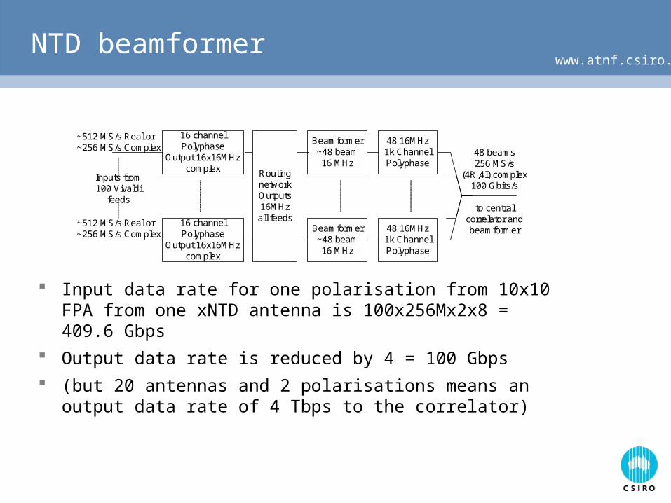
Input data rate for one polarisation from 10x10 FPA from one xNTD antenna is 100x256Mx2x8 = 409.6 Gbps
Output data rate is reduced by 4 = 100 Gbps
(but 20 antennas and 2 polarisations means an output data rate of 4 Tbps to the correlator)
www.atnf.csiro.auPossible xNTD correlator
8 antenna2 beam
Router andBuffer
8 antenna2 beam
Router andBuffer
8 antenna2 beam
Router andBuffer
Beam 1 HFRouter and data
serialiserXC4VFX20
Beam 2 LFRouter and data
serialiserXC4VFX20
Beam 2 HFRouter and data
serialiserXC4VFX20
Beam 1 LFRouter and data
serialiserXC4VFX20
HF CorrelatorBeam 1
2 x XC4VSX35
LF CorrelatorBeam 1
2 x XC4VSX35
HF CorrelatorBeam 2
2 x XC4VSX35
LF CorrelatorBeam 2
2 x XC4VSX35
Correlator BoardDual RocketI/O Links2x8 Gb/s
LTA
DDR2
DDR2 DDR2
LTA
DDR2
DDR2 DDR2
LTA
DDR2
DDR2 DDR2
LTA
DDR2
DDR2 DDR2
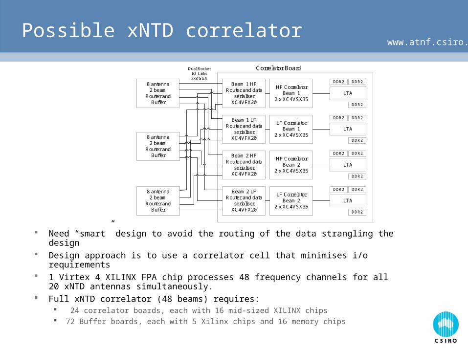
Need “smart” design to avoid the routing of the data strangling the design Design approach is to use a correlator cell that minimises i/o requirements 1 Virtex 4 XILINX FPA chip processes 48 frequency channels for all 20
xNTD antennas simultaneously. Full xNTD correlator (48 beams) requires:
24 correlator boards, each with 16 mid-sized XILINX chips 72 Buffer boards, each with 5 Xilinx chips and 16 memory chips
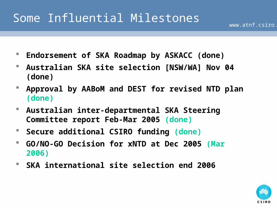
www.atnf.csiro.auSome Influential Milestones
Endorsement of SKA Roadmap by ASKACC (done)
Australian SKA site selection [NSW/WA] Nov 04 (done)
Approval by AABoM and DEST for revised NTD plan (done)
Australian inter-departmental SKA Steering Committee report Feb-Mar 2005 (done)
Secure additional CSIRO funding (done)
GO/NO-GO Decision for xNTD at Dec 2005 (Mar 2006)
SKA international site selection end 2006
Focal Plane Arrays for the New Technology
Demonstrator
John Kot, Stuart Hay, Nasiha Nikolic, Doug Hayman, Christophe Granet
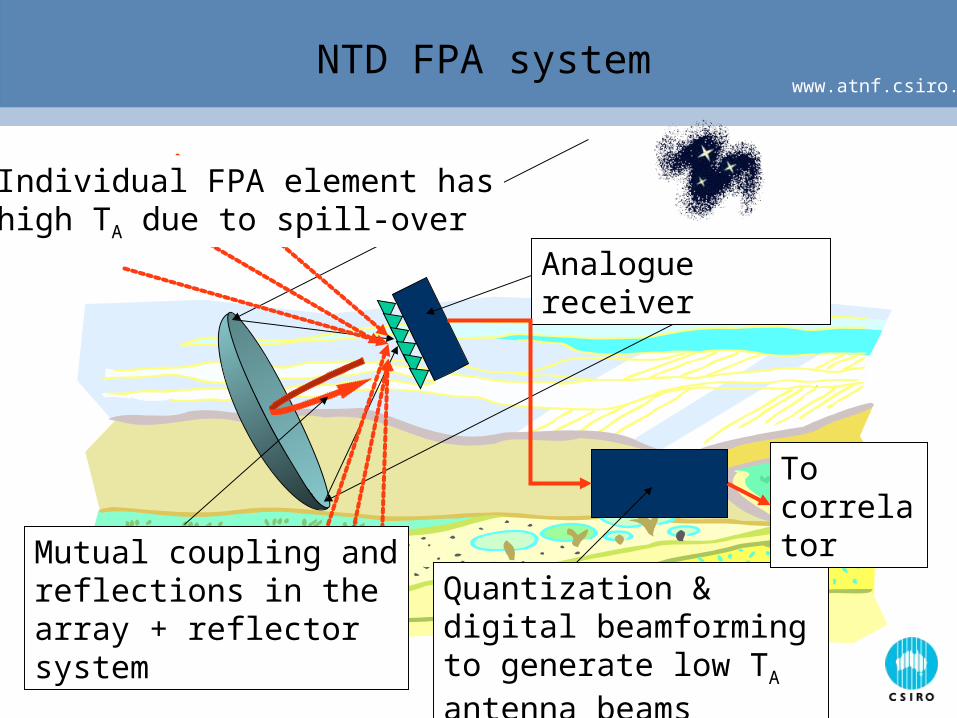
www.atnf.csiro.au NTD FPA system
Individual FPA element hashigh TA due to spill-over
Mutual coupling and reflections in the array + reflector system
Quantization & digital beamforming to generate low TA antenna beams
Analogue receiver
To correlator
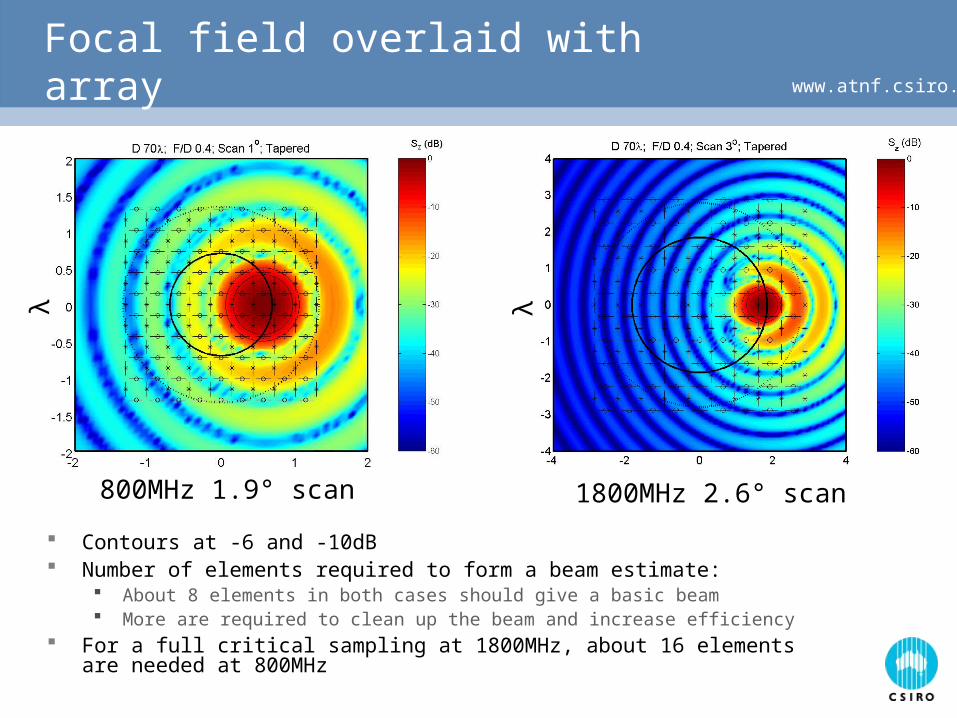
www.atnf.csiro.auFocal field overlaid with array
Contours at -6 and -10dB Number of elements required to form a beam estimate:
About 8 elements in both cases should give a basic beam More are required to clean up the beam and increase efficiency
For a full critical sampling at 1800MHz, about 16 elements are needed at 800MHz
800MHz 1.9° scan 1800MHz 2.6° scan
λ λ
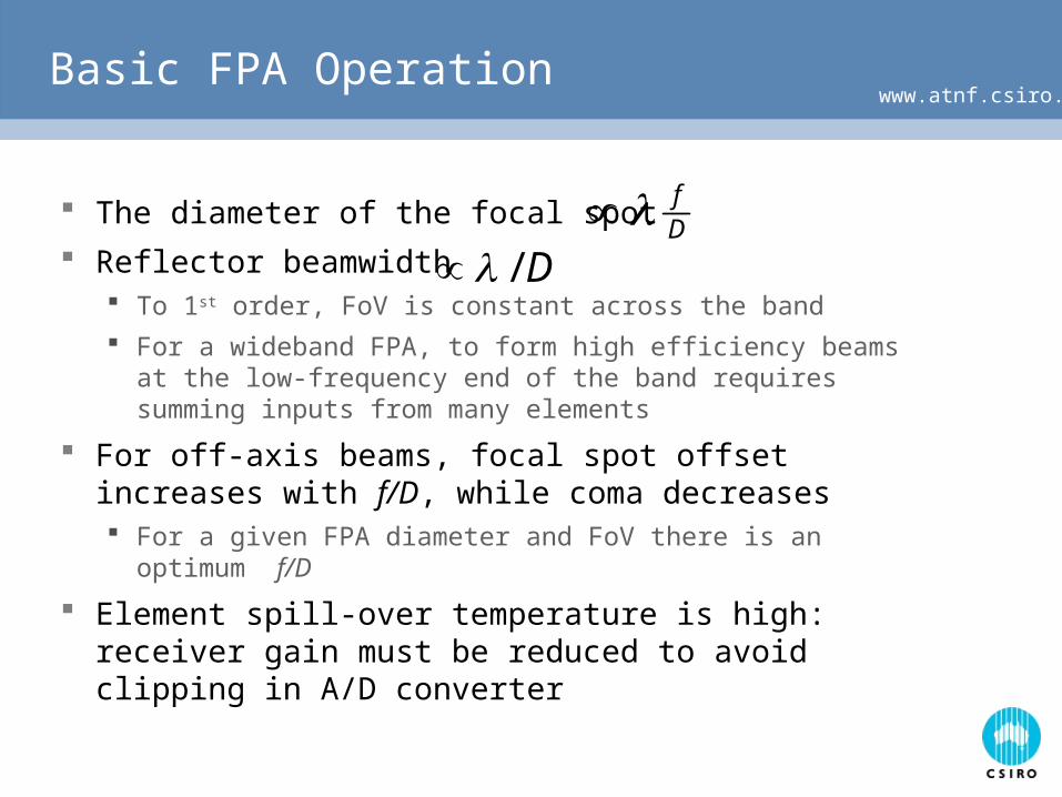
www.atnf.csiro.auBasic FPA Operation
The diameter of the focal spot
Reflector beamwidth To 1st order, FoV is constant across the band
For a wideband FPA, to form high efficiency beams at the low-frequency end of the band requires summing inputs from many elements
For off-axis beams, focal spot offset increases with f/D, while coma decreases For a given FPA diameter and FoV there is an optimum f/D
Element spill-over temperature is high: receiver gain must be reduced to avoid clipping in A/D converter
Df
D/
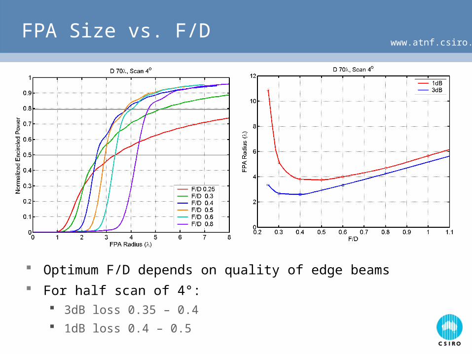
www.atnf.csiro.auFPA Size vs. F/D
Optimum F/D depends on quality of edge beams
For half scan of 4°: 3dB loss 0.35 – 0.4
1dB loss 0.4 – 0.5
www.atnf.csiro.au
Low noise operation with a wideband, uncooled FPA
FPA element impedance is strongly determined by array effects (tendency for large variations with frequency)
For a small FPA of identical elements, the element impedances are all different (modulo symmetry)
LNA noise contributions: self noise + coupled radiated noise from all other LNAs
We need to do a lot of work to understand how to achieve optimum low noise operation – it is far from straight forward
www.atnf.csiro.auOngoing efforts towards an NTF FPA
CSIRO has signed an agreement with U. Mass. and ASTRON for joint development of a ”Vivaldi” FPA for 800MHz – 1.8GHz Avoid “re-inventing the wheel” Mitigate a major risk with the NTD project
Development of a model for a narrow band “egg-crate” array of dipole feeds with a reflector Gives us a simple, analytic model to study representative
FPA effects such as: noise coupling; element spacing; offset between dual-polarized array elements; interaction between array and reflector (“cavity effect”)
Allows us to explore more of the parameter space than currently possible with a finite element / boundary element computational model
www.atnf.csiro.auOngoing efforts towards an NTF FPA (2)
Investigation of alternative array elements & tilings Non-ideal aspects of uniform Vivaldi arrays: polarization
and large excursions in element impedance Other elements may be better, e.g. arrays derived from
self-complementary screens have very large impedance bandwidth
Non-uniform arrays may compensate for “small array” effect, or offer much larger bandwidths (foveated arrays)
Close cooperation between antenna, RF, and DSP engineers to understand system aspects of FPA Investigation of options such as balanced vs.
conventional LNA Understanding of how array & reflector choices affect
beamformer complexity
www.atnf.csiro.auOngoing efforts towards an NTF FPA (3)
Development of a comprehensive LNA + FPA + reflector model, using a generalized scattering matrix model Will allow us to investigate beamforming for optimization
of A / Tsys taking into account effects such as noise coupling and cavity effect, using accurate models for FPA and reflector and / or measured results

The End