june 2011 hydratect 2462 steam/water detection system€¦ · · 2018-03-03hydratect 2462...
TRANSCRIPT

Hydratect 2462 Steam/Water Detection System
Hydratect 2462ETechnical Manual 24625009, Rev. AC June 2011
www.emersonprocess.com

ii

iii
GENERAL SAFETY PRECAUTIONS
The equipment described in this manual has been designed in accordance with EN61010 “Safety requirements for electrical equipment for measurement, control and laboratory use”, and has been supplied in a safe condition. To avoid injury to an operator or service technician the safety precautions given below, and throughout the manual, must be strictly adhered to whenever the equipment is operated, services or repaired. For specific safety details, please refer to the relevant sections within the manual.
The equipment is designed solely for electronic measurement and should be used for no other purpose. Rosemount Measurement accepts no responsibility for accidents or damage resulting from failure to comply with these precautions.
CLEANING To clean the instrument, use a damp cloth with a mild, water-based cleaner. Clean the exterior of the instrument only. Do not allow liquids to enter or spill onto the instrument.
GROUNDING To minimise the hazard of electrical shock, it is essential that the equipment be connected to a protective ground whenever the power supply, measurement or control circuits are connected, even if the equipment is switched off.
The electronics unit must be connected to ground using the marked case stud before control or signal leads are connected. The ground connections must have a current rating of 25A.
AC SUPPLY Never operate the equipment from a line voltage or frequency in excess of that specified. Otherwise, the insulation of internal components may break down and cause excessive leakage currents.
To allow the electronics unit to be isolated from the ac supply, the supply must be routed through a switch (or circuit breaker). The switch (or circuit breaker) must be within easy reach of the operator and must be clearly identified as the means of supply isolation. The maximum current drawn from the supply must be limited by a fuse or trip, to a maximum of 13A.
FUSES Before switching on the equipment, check that the fuses accessible from the interior of the equipment are of the correct rating. The rating of the ac line fuse must be in accordance with the voltage of the ac supply.
Should any fuse continually blow, do not insert a fuse of a higher rating. Switch the equipment off, clearly label it “unserviceable” and inform a service technician.
EXPLOSIVE ATMOSPHERES NEVER OPERATE the equipment, or any sensors connected to the equipment, in a potentially explosive atmosphere. It is NOT intrinsically safe and could possibly cause an explosion
Continued overleaf.

iv
SAFETY PRECAUTIONS (continued from previous page)
SAFETY SYMBOLS For the guidance and protection of the user, the following safety symbols appear on the equipment:
SYMBOL: MEANING:
NOTES, CAUTIONS AND WARNINGS For the guidance and protection of the user, Notes, Cautions and Warnings appear throughout the manual. The significance of these are is as follows:
NOTES – highlight important information for the reader’s special attention
CAUTIONS – guide the reader in avoiding damage to the equipment
WARNINGS – guide the reader in avoiding a hazard that could cause injury or death.
AVOID UNSAFE EQUIPMENT The equipment may be unsafe if any of the following statements apply:
Equipment shows visible damage Equipment has failed to perform an intended operation Equipment has been subjected to prolonged storage under unfavourable
conditions Equipment has been subjected to severe physical stress.
If in any doubt as to the serviceability of the equipment, don’t use it. Get it properly checked out by a qualified service technician.
LIVE CONDUCTORS When the equipment is connected to its’ supply, the opening of covers or removal of parts could expose live conductors. The equipment must be disconnected from all power and signal sources before it is opened for any adjustment, replacement, maintenance or repair. Adjustment, maintenance and repairs must be must be done by qualified personnel, who should refer to the Maintenance Manual.
DO NOT OPEN THE ELECTRONICS UNIT WHEN IT IS ENERGISED.
EQUIPMENT MODIFICATION To avoid introducing safety hazards, never install non-standard parts in the equipment, or make any unauthorised modification. To maintain safety, always return the equipment to Rosemount Measurement for service and repair.
Fault indicator. Refer to Operating Manual for detailed instructions of use.
Hazardous voltages.

v
Hydratect 2462E Technical Manual Contents
Chapter 1 Introduction: Hydratect 2462
1.1 What Hydratect Does
1.2 The Hydratect 2462 Variants
1.3 Electrode: Principle of Operation
1.4 Specification
Chapter 2 Installing the Electrodes
2.1 Electrode Installation Methods
2.2 Mounting a Series III Electrode on an Insert
2.3 Mounting a Series III Electrode on a Manifold
2.4 Typical Installations
2.5 Customised Manifolds
Chapter 3 Installing the Electronics Unit
3.1 Installation Summary
3.2 Fitting Cable Glands to the 2462 Case
3.3 Mounting the 2462 Case
3.4 Setting the PCB Jumpers
3.5 Connecting the Electronics
Chapter 4 Testing the Hydratect 2462
4.1 Test Summary
4.2 Testing the Electrodes
Chapter 5 Servicing the Electrodes
5.1 Service Summary
5.2 Periodic Check
5.3 Repairing an Electrode
5.4 Periodic System Overhaul
5.5 Electrode Replacement Parts
Chapter 6 Servicing the Electronics
6.1 Fault Diagnosis
6.2 Correcting a Fault

vi

Hydratect 2462E Technical Manual
24625009 1-1
1
Introduction: Hydratect 2462
Contents 1.1 WHAT HYDRATECT 2462 DOES 1-3
1.1.1 Steam or water detection 1-3 1.1.2 Contamination detection 1-3 1.1.3 Fail Safe Operation 1-4
1.2 ELECTRODES: PRINCIPLES OF OPERATION 1-5
1.3 SPECIFICATION 1-7
List of Figures Figure 1.1: The 2462 Hydratect Electronics Unit ..................................................................................... 1-2
Figure 1.2: Electrode - Principle of operation ........................................................................................... 1-5
List of Tables Table 1.2: LED and Relay States for Electrode, Water-Normal ............................................................... 1-6
Table 1.3: LED and Relay States for Electrode, Steam-Normal .............................................................. 1-6

Hydratect 2462E Technical Manual Introduction: Hydratect 2462
1-2 24625009
Figure 1.1: The 2462 Hydratect Electronics Unit

Introduction: Hydratect 2462 Hydratect 2462E Technical Manual
24625009 1-3
1.1 WHAT HYDRATECT 2462 DOES
Hydratect 2462 is the electronic alternative to conventional water level switches on steam raising plant.
The Hydratect 2462 system consists of a compact twin-channel electronic unit, connected to a pair of electrodes that are mounted in the plant pipe-work. (See Figure 1.1) Each channel gives independent indications of the presence of water or steam that are more reliable than those obtained with conventional electro-mechanical devices. The electronics unit also provides a local indication of steam, water and fault states, and features configurable fault and trip outputs. Typical applications of Hydratect 2462 are (1) low or high-level water detection and (2) the detection of water in steam line drain pots to prevent water induction.
1.1.1 Steam or water detection
On each electrically isolated channel, Hydratect discriminates between steam and water by comparing the electrode resistance with a reference value. A resistance greater than the reference value indicates steam and a resistance less than the reference value indicates water. Two alternative reference values (0.6S/cm and 1.6S/cm) are selectable by a Jumper to give high or low sensitivity, to suit the operating conditions and the purity of the boiler water.
Detection of steam or water is indicated on the front panel of the Hydratect unit by the illumination of a red or green LED. (See Figure 1.1) To control any external equipment, Hydratect provides status outputs from either a relay or a solid-state switch option to indicate the detected state. The status relay option provides both normally-open and normally-closed contact outputs. By means of Jumpers, each channel can be set, individually, for water-normal or steam-normal. It is essential that the Jumpers be set to correspond with the normal state of the system: this allows the status output to default to the not normal state, should Hydratect develop a fault. For example, when a steam normal channel monitoring a steam line detects water the status relay is de-energised. The normally-open status contacts close and the normally-closed contacts open. A latch is available for the status relay, which, once activated, holds the relay in the “not normal” state until reset.
1.1.2 Contamination detection
To prevent a build-up of contamination causing a false indication, a contamination detection circuit is operated in parallel with the steam/water discriminator. By means of Jumpers, the error threshold of the contamination detection circuit can be set for high sensitivity or low sensitivity. If it is not required, the circuit can be inhibited. Should contamination be detected then a fault on the relevant channel is indicated by the front panel fault LED and the fault output. In the relay output version, the relay is de-energised, providing both normally-open and normally-closed contacts for use by external equipment.

Hydratect 2462E Technical Manual Introduction: Hydratect 2462
1-4 24625009
1.1.3 Fail Safe Operation
For reliability, each channel of Hydratect has it’s own power supply. Hydratect continuously monitors itself for component failure, cable faults, ground faults and electrode problems. Components outside the self-monitoring loop are in triplicate. Component failures, or the failure of a power supply, are indicated by the fault LED and cause the fault and/or status relays to be de-energised. Hydratect self-checking extends to the signal and ground cable terminations at the electrodes. Should one or more conductors become detached, the fault LED is illuminated and the fault relay is de-energised. For trip purposes, signals can be validated by connecting the status outputs in a ‘one out of two’ or ‘two out of two’ tripping scheme. Typical applications are shown in Chapter 2, Section 5. The connections are shown in Chapter 3.

Introduction: Hydratect 2462 Hydratect 2462E Technical Manual
24625009 1-5
1.2 ELECTRODES: PRINCIPLES OF OPERATION
The principle operation of an electrode is explained and illustrated in Figure 1.2.
Temperature (°F)
HYDRATECT SW ITCHING BAND - ALTERNATE
TYPICAL STEAM VALUES
HYDRATECT SW ITCHING BAND - NORMAL
0.01
0.1
1
10
100 200 300
Temperature (°C)
Co
nd
uc
tivity
(S
/cm
)
TYPICAL BOILER WATER
200 400 500 600100 700
1000
10,000
100
10
1100
Re
sis
tan
ce
(k
) k
=0
.1
PureWater
300
Steam
Water
Signal amplitude proportionalto electrode resistance:
0V Detection
0V
DriveResistor
Drive (~±6V)
Hydratect 2462
Figure 1.2: Electrode - Principle of operation
As shown above, the signal returned by the electrode is proportional to the resistance between the electrode tip and ground. This allows the 2462 Electronic Unit to detect the presence of steam or water. A signal whose amplitude is very small represents a fault – for example, a broken wire or a short-circuit.
The graph (inset) shows conductivity and resistance values of steam, pure water and typical boiler water.
The significant difference between the resistance of steam and boiler water allows Hydratect to differentiate between the two.
An electrode, inserted into the pipe containing the steam or water, acts as a resistor. The resistance values are >10M for steam and between 2k and 100k for boiler water. In the Hydratect 2462 Electronics Unit, the electrode resistance forms the lower half of a potential divider, across which an alternating driving signal is applied. The signal amplitude of the potential divider output is high (~6V) for steam and low (~3V) for water

Hydratect 2462E Technical Manual Introduction: Hydratect 2462
1-6 24625009
To obtain consistent resistance values, each type of electrode and the insert or manifold in which it is mounted are designed for a common cell constant of 0.1. This gives a resistance of between 2k and 100k for typical boiler water, and a resistance greater than 10M for steam.
To enable the 2462 Electronics Unit to detect an open circuit, each connection to the electrode is terminated individually through a nickel crimped terminal ring. Details for the correct connections are given in Chapter 3.
To avoid electrolytic action, the electrode is driven by an alternating signal. The low frequency of this signal ensures that the signal returned by the electrode is unaffected by the cable capacitance. The ways in which the LEDs and output relays of Hydratect reflect the system state for electrodes are summarised in Table 1.1 and Table 1.2.
Table 1.1: LED and Relay States for Electrode, Water-Normal
System State Front Panel LEDs Output Relays
! Steam Water Fault Status Normal
Electrode in water, no fault Off Off On Energised Energised
Electrode in steam, no fault Off On Off Energised De-energised
Power supply loss Off Off Off De-energised De-energised
Electrode contaminated or short-circuited On Off On De-energised Energised
Connection in electrode sense element is broken On Off On De-energised Energised
Connection in electrode ground is broken On Off On De-energised Energised
Connection to ground sense is broken – electrode in water On Off On De-energised Energised
Connection to ground sense is broken – electrode in steam On On Off De-energised De-energised
Table 1.2: LED and Relay States for Electrode, Steam-Normal
System State Front Panel LEDs Output Relays
! Steam Water Fault Status Normal
Electrode in steam, no fault Off On Off Energised Energised
Electrode in water, no fault Off Off On Energised De-energised
Power supply loss Off Off Off De-energised De-energised
Electrode contaminated or short-circuited On Off On De-energised De-Energised
Connection in electrode sense element is broken On Off On De-energised De-Energised
Connection in electrode ground is broken On Off On De-energised De-Energised
Connection to ground sense is broken – electrode in water On Off On De-energised De-energised
Connection to ground sense is broken – electrode in steam On On Off De-energised Energised

Introduction: Hydratect 2462 Hydratect 2462E Technical Manual
24625009 1-7
1.3 SPECIFICATION
Enclosure 190mm x 190mm x 90mm deep. Stainless steel, grade 304. Wall mounting, two point. IP65 / NEMA 4X. Weight 2.8 Kg (6.2 lb) Operating Temperature -20C to +70C (-4F to 158F) Relative Humidity Up to 100% Location Indoor or outdoors Power Supply (ac) 93.5 – 130Vac or 187 – 256Vac, 48Hz – 65Hz. 2x10VA maximum. Fuse: 1.25mA (SLO-BLO), 20mm Electrical Connectors Plug-in screw terminals. Maximum gauge 16AWG (1.5mm2) Electrode Cable Length 30m (98ft) maximum Electrode Channels 2 Water/Steam Threshold 0.6S/cm (normal) or 1.6S/cm (alternate) Fault Detection Broken wire to electrode, Short-circuit to ground, Any component failure to prEN50156 Indication (per channel) Red LED (On = Steam), Green LED (On = Water), Amber LED (On = Fault) Status Relay Output Energised for normal status, steam or water, (2-pole changeover) Separate normally-open and normally-closed contacts, 250Vac, 8A maximum, 225Vdc, 0.25A Fault Relay Output Energised during normal operation (fail-safe), (2-pole changeover) Separate normally-open and normally-closed contacts, 250Vac, 8A maximum, 225Vdc, 0.25A

Hydratect 2462E Technical Manual Introduction: Hydratect 2462
1-8 24625009

Hydratect 2462E Technical Manual
24625009 2-1
2
Installing the Electrodes
Contents
2.1 ELECTRODE INSTALLATION METHODS ................................................................................... 2-3
2.2 MOUNTING A SERIES III ELECTRODE ON AN INSERT ............................................................ 2-4
2.2.1 Installing the Insert ............................................................................................................... 2-4 2.2.2 Fitting the Insert Electrode Cover ......................................................................................... 2-6 2.2.3 Fitting the electrode .............................................................................................................. 2-6 2.2.4 Fitting the Insert Electrode Cover ......................................................................................... 2-7
2.3 MOUNTING SERIES III ELECTRODES ON A MANIFOLD .......................................................... 2-8
2.4 TYPICAL INSTALLATIONS .......................................................................................................... 2-9
2.4.1 High/Low water level detection In a boiler drum .................................................................. 2-9 2.4.2 High water level detection in a drain pot ............................................................................ 2-11
2.5 CUSTOMISED MANIFOLDS ....................................................................................................... 2-12
List of Figures FIGURE 2.1: APERTURE DIMENSIONS ................................................................................................... 2-4
FIGURE 2.2: FITTING THE INSERT .......................................................................................................... 2-4
FIGURE 2.3: CHECK ON INNER EDGE OF CIRCULAR GROOVE .......................................................... 2-5
FIGURE 2.4: WELDING OF ELECTRODE INSERT ................................................................................... 2-5
FIGURE 2.5: FITTING THE INSERT ELECTRODE COVER ..................................................................... 2-7
FIGURE 2.6: SERIES III MANIFOLD – SIDEARM AND INLINE VERSIONS ............................................ 2-8
FIGURE 2.7: WATER LEVEL DETECTION IN A BOILER DRUM, USING A SIDEARM MANIFOLD ..... 2-10
FIGURE 2.8: MANIFOLD CONNECTION DETAILS ................................................................................. 2-10
FIGURE 2.9: WATER LEVEL DETECTION IN A DRAIN POT, USING AN IN-LINE MANIFOLD ............ 2-11
FIGURE 2.10: SIDE-COUPLED CUSTOMISED MANIFOLD, WITH VENT AND DRAIN ........................ 2-12
FIGURE 2.11: ONE, TWO, THREE AND FOUR-PORT OPTIONS OF CUSTOMISED MANIFOLD ....... 2-12
List of Tables TABLE 2.1: ELECTRODES FOR USE WITH THE HYDRATECT 2462 .................................................. 2-3

Hydratect 2462E Technical Manual Installing the Electrodes
2-2 24625009

Installing the Electrodes Hydratect 2462E Technical Manual
24625009 2-3
2.1 ELECTRODE INSTALLATION METHODS
The electrodes available for use with Hydratect are listed in Table 2.1. For an electrode to function correctly it must be contained in a ‘cell’ of known volume. This allows the 2462 Electronics Unit to differentiate between the resistance of a known volume of steam and the same volume of water. For this reason, Hydratect electrodes are mounted either in an insert or in a manifold. An insert provides for the mounting of a single electrode, whilst the manifold provides for the mounting of up to four electrodes.
Table 2.1: Electrodes for Use with the Hydratect 2462
Part Number Maximum Pressure
Maximum Temperature
PH Range
Insulation Type Application
246785Z 210bar (3045psi) 370C (698F) 7-11 Zirconia High pressure
246785A 300bar (4350psi) 560C (1040F) 7-11 ZTA High pressure
246785P 50bar (725psi) 260C (500F) 11-13.5 PTFE Low pressure

Hydratect 2462E Technical Manual Installing the Electrodes
2-4 24625009
2.2 MOUNTING A SERIES III ELECTRODE ON AN INSERT
Mounting an electrode on an insert involves four steps:
1 Welding the insert into the pipe………………………… Section 2.2.1
2 Fitting the base plate to the electrode cover…….……. Section 2.2.2
3 Fitting the electrode to the insert……………….……… Section 2.2.3
4 Fitting the insert electrode cover……...……………… Section 2.2.4
2.2.1 INSTALLING THE INSERT
Follow these instructions:
1 Ensure that an aperture of the following dimensions has been cut in the pipe, ready to receive the insert. (Any swarf must be removed from the pipe-work prior to testing the system)
Figure 2.1: Aperture Dimensions
2 Fit the insert into the prepared aperture, ensuring that the orientation slot is pointing downwards.
Figure 2.2: Fitting the Insert
Note: The alternative is to use a manifold. This is detailed in Section 2.3 (page 2-8).

Installing the Electrodes Hydratect 2462E Technical Manual
24625009 2-5
3 Check that the inner edge of the circular groove around the insert body is level with the bottom of the weld preparation:
Figure 2.3: Check on inner edge of circular groove
4 Weld the electrode insert in place. The welding procedure must accord with the National or Regional Codes of Practice for Joining Dissimilar Metals.
(Note: The insert material is Stainless Steel SA479 316N / X2 CRNIMON 17/13/3)
Figure 2.4: Welding of Electrode Insert
Take care not to damage the thread or conical seat on the electrode insert. The cast/lot number on the insert must not be obscured by welding.

Hydratect 2462E Technical Manual Installing the Electrodes
2-6 24625009
2.2.2 Fitting the Insert Electrode Cover
The base plate of the electrode cover is screwed onto the electrode insert on the same thread as that used for the electrode nut. Therefore, the procedure for installing the electrode cover is in two parts.
The first part of the procedure is given below. When you have completed this, install the electrode as described in Section 2.2.3. Then go on to complete the installation of the Insert Electrode Cover, as described in Section 2.2.4
1 Dismantle the electrode cover assembly into its component parts:
(a) the base plate (complete with the top plate securing studs),
(b) the top plate,
(c) the main cylindrical housing.
2 Screw the base plate onto the electrode insert and tighten it down with a strap wrench.
2.2.3 Fitting the electrode
Electrodes are supplied complete with fixing nuts, termination nuts and washers. To avoid damage, the electrodes should be kept in their packaging until they are installed.
The installation procedure is:
1 Carefully unpack the electrode and check that there is no damage, either to the ceramicinsulators or to the electrode seating.
(In the event of discovering damage to the electrode, contact your Rosemount Measurement agent for replacement of the defective item. If the insert seat has been inadvertently scored it can be re-cut to an acceptable standard using the appropriate service tool listed below.)
Service Tool 246791AA – for use with electrodes 246785A and 246785Z only Service Tool 246722AA – for use with electrode 246785P only
2 To alleviate thread seizure problems, lightly coat the thread of the insert with anti-seizecompound (Rosemount Measurement part number 830007220)
3 Ease the electrode into the insert and then turn the electrode fixing nut, clockwise, with yourfingers to engage the threads
4 Using a long-reach 25mm AF socket spanner, gradually tighten the electrode fixing nut untilthe electrode will not rotate in its’ seat
5 Finally, tighten the electrode nut a further 1/8th to ¼ turn to complete the procedure.
High Pressure Electrode Note: The final 1/8th to ¼ turn corresponds to a torque level of between 28lbft (35Nm) and 47lbft (60Nm). The 1/8th turn is the recommended tightening condition, ¼ is the maximum allowable, and the tightening torque used must be the minimum to achieve this. Failure to comply with this limitation may cause damage to the port or to the electrode from over tightening.
Installing the Electrodes Hydratect 2462E Technical Manual
24625009 2-7
2.2.4 Fitting the Insert Electrode Cover
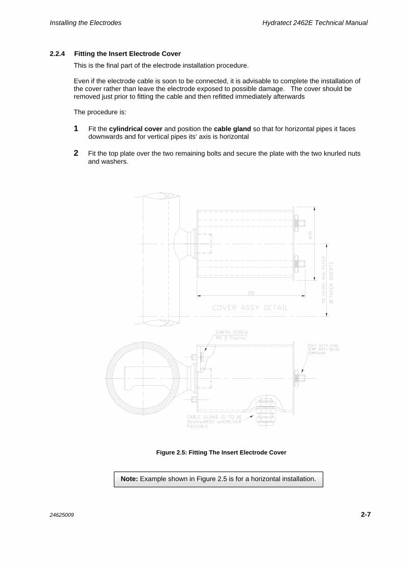
This is the final part of the electrode installation procedure. Even if the electrode cable is soon to be connected, it is advisable to complete the installation of the cover rather than leave the electrode exposed to possible damage. The cover should be removed just prior to fitting the cable and then refitted immediately afterwards The procedure is: 1 Fit the cylindrical cover and position the cable gland so that for horizontal pipes it faces
downwards and for vertical pipes its’ axis is horizontal 2 Fit the top plate over the two remaining bolts and secure the plate with the two knurled nuts
and washers.
Figure 2.5: Fitting The Insert Electrode Cover
Note: Example shown in Figure 2.5 is for a horizontal installation.

Hydratect 2462E Technical Manual Installing the Electrodes
2-8 24625009
2.3 MOUNTING SERIES III ELECTRODES ON A MANIFOLD
This is the alternative to installing inserts, which were covered in Section 2.2 (page 2-4).
Figure 2.6: Series III Manifold – Sidearm and Inline Versions
The procedure is:
1 Remove the electrode cover, and the port dust cap(s)
2 Temporarily cover the manifold port(s) with heat resistant material, to prevent the ingress of weld splatter and dirt
3 Weld the manifold in place, using the procedure recommended by the National or Regional Codes of Practice
4 Install electrodes in the manifold ports. The fitting procedure is described in Section 2.2.3
5 When all electrodes have been installed in the manifold, replace the electrode covers and secure them
Even if the electrode cable is soon to be connected, it is advisable to complete the installation of the cover rather than leave the electrode exposed to possible damage.
The electrode cover should be removed just prior to fitting the cable and then refitted immediately afterwards.

Installing the Electrodes Hydratect 2462E Technical Manual
24625009 2-9
2.4 TYPICAL INSTALLATIONS
Two typical Hydratect installations are described in Sections 2.4.1 and 2.4.2. One installation monitors the water level in a boiler drum. The other installation monitors the water level in a drain pot.
2.4.1 High/Low water level detection In a boiler drum
A Hydratect 2462 system for detecting high and low water levels in a boiler drum is shown in Figure 2.7. Each of the validated trip signals results from a “two out of two” configuration in the Hydratect electronics unit. For example, the high trip signal occurs only when water is present at both the high and the high-high level electrodes. This particular system uses a sidearm manifold 1 for detecting intermediate water levels between high and low. Connection information for the manifold pipework is given in Figure 2.8. Note the following points: The connecting pipework must be sloped as indicated in Figure 2.8. This is done to ensure a
flow of condensate through the manifold The isolating valves, when opened, should allow unrestricted flow through the manifold.
Full-bore globe valves are highly recommended. These valves should be installed with the handle spindle horizontal.
The connecting pipework must be insulated, as shown by the hatched marking in Figure 2.8.
1 The manifold may use electrodes as used in the Hydrastep 2468 system. Details can be found in a Hydrastep 2468 Series
Operating Manual.

Hydratect 2462E Technical Manual Installing the Electrodes
2-10 24625009
Figure 2.7: Water level detection in a boiler drum, using a sidearm manifold
Figure 2.8: Manifold connection details
Installing the Electrodes Hydratect 2462E Technical Manual
24625009 2-11
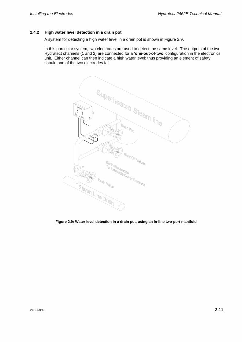
2.4.2 High water level detection in a drain pot
A system for detecting a high water level in a drain pot is shown in Figure 2.9. In this particular system, two electrodes are used to detect the same level. The outputs of the two Hydratect channels (1 and 2) are connected for a ‘one-out-of-two’ configuration in the electronics unit. Either channel can then indicate a high water level: thus providing an element of safety should one of the two electrodes fail.
Figure 2.9: Water level detection in a drain pot, using an In-line two-port manifold

Hydratect 2462E Technical Manual Installing the Electrodes
2-12 24625009
2.5 CUSTOMISED MANIFOLDS
Figure 2.10 and Figure 2.11 show details of one, two, three and four-port customised manifolds. These manifolds can be made-to-order, to suit a customer requirement. They are side-coupled to the connecting pipework and vertically mounted. Separate vent and drain connections are provided.
Figure 2.10: Side-coupled customised manifold, with vent and drain
Figure 2.11: One, Two, Three and Four-Port options of the customised manifold

Hydratect 2462E Technical Manual
24625009 3-1
3
Installing The Electronics Unit
Contents
3.1 INSTALLATION SUMMARY ......................................................................................................... 3-3
3.2 FITTING CABLE GLANDS TO THE 2462 CASE ......................................................................... 3-4
3.3 MOUNTING THE 2462 CASE ....................................................................................................... 3-5
3.4 SETTING THE PCB JUMPERS .................................................................................................... 3-6
3.5 CONNECTING THE ELECTRONICS ............................................................................................ 3-9
3.5.1 Preparing the Electrode Cables .......................................................................................... 3-9 3.5.2 Preparing the fault/status relay cables ............................................................................. 3-13 3.5.3 Preparing the power supply cables .................................................................................. 3-15 3.5.4 Connecting the prepared cables to the front panel........................................................... 3-16
List of Figures FIGURE 3.1: CABLE GLAND MOUNTING AREA ON UNDERSIDE OF 2462 CASE ............................ 3-4
FIGURE 3.2: DIMENSIONS OF THE HYDRATECT 2462 CASE ............................................................ 3-6
FIGURE 3.3: DEFAULT JUMPER SETTINGS ......................................................................................... 3-7
FIGURE 3.4: PCB JUMPER LOCATIONS ............................................................................................... 3-8
FIGURE 3.5: DETAILS OF THE INSERT MOUNTED ELECTRODE COVER ...................................... 3-11
FIGURE 3.6: CABLE CONNECTIONS TO AN ELECTRODE ............................................................... 3-11
FIGURE 3.7: FITTING THE ELECTRODE CABLE TO THE 8-WAY CONNECTOR ............................. 3-12
FIGURE 3.8: STATUS, FAULT AND STATUS LATCHING RESET CONNECTIONS .......................... 3-14
FIGURE 3.9: POWER SUPPLY CONNECTIONS ................................................................................. 3-15
FIGURE 3.10: CONNECTOR LOCATIONS ON FRONT PANEL PCB ................................................. 3-16
List of Tables TABLE 3.1: JUMPER SETTINGS FOR OPTIONS .................................................................................. 3-7
TABLE 3.2: ELECTRODE CABLE AVAILABILITY .................................................................................. 3-9

Hydratect 2462E Technical Manual Installing The Electronics Unit
3-2 24625009

Installing The Electronics Unit Hydratect 2462E Technical Manual
24625009 3-3
3.1 INSTALLATION SUMMARY
The basic steps to installing the Hydratect 2462 electronics unit are as follows: 1 Fit cable glands to the base of the unit case. For this, a number of holes will need to be cut
through 1.6mm of stainless steel. Hole sizes will depend on the type of gland to be fitted. Section 3.2 of this Chapter is a guide to this procedure
2 Mount the case in a suitable position. The case is bolted in position through two lugs;
provision will have to be made for the bolt fixtures. THE CASE MUST BE BONDED TO GROUND THROUGH A SUITABLY RATED CABLE AND GROUNDING POINT. The dimensions of the case, the mounting procedure and grounding procedure are given in Section 3.3 of this Chapter
3 Select the various 2462 options with the Jumpers (plug-links) on the internal PCB. The
Jumpers and their functions are described in Section 3.4 of this Chapter 4 Prepare and connect various cables to the 2462 front panel. These are for the electrodes,
the fault and status relay outputs, and the power supplies. When the status relay latch option is fitted, a connection is also required for the latch reset input. Cable connections are described in Section 3.5 of this Chapter.
When the electrodes and the electronics unit have been installed, as described in Chapters 2 and 3, Hydratect can be tested. The test procedure is given in Chapter 4.
Note:
When re-securing the front panel of the unit with the four captive screws, ensure that the four washers make complete contact with the metalwork of the front panel. The label (art work) on the front panel must not be trapped under these washers.

Hydratect 2462E Technical Manual Installing The Electronics Unit
3-4 24625009
3.2 FITTING CABLE GLANDS TO THE 2462 CASE
To ensure that the interior of the 2462 electronics unit remains effectively sealed against the ingress of moisture, cables must enter the unit through suitable cable glands. The type of glands used will vary according to locale and application. It is essential to use screened cables and RF glands that give a good annular (ring shaped) connection to the cable screens to ensure EMC compliance in European installations. The IP rating of the finished enclosure is another consideration. For this reason, it has been left to the installation engineer to arrange for suitable holes to be cut in the underside of the unit when the type of glands to be used is known. To avoid the glands or cables fouling the internal connectors, the area for mounting the glands has been restricted to that shown in Figure 3.1. The only constraint within this area is that the distance between the peripheries of adjacent holes must not be less than 9mm. Should only one channel be required for use then the holes for this should be located towards the rear of the unit, thus leaving the maximum amount of room between cables and the PCB.
Permitted area for mountingcable glands
120mm
60mm
9mm
Figure 3.1: Cable gland mounting area on underside of 2462 case
The procedure for fitting cable glands is: 1 Undo the four bolts that secure the front panel of the electronics unit to the case. Carefully
remove the panel from the case 2 Store the front panel in a safe place
(The panel has mounted on it all the electronic circuitry and must be protected against adverse conditions such as heat, dust and static electricity)
3 Arrange for holes of a suitable diameter and location to be cut in the underside of the unit,
within the permitted area shown in Figure 3.1. The case should now be mounted in the intended location, as described in 3.3.

Installing The Electronics Unit Hydratect 2462E Technical Manual
24625009 3-5
3.3 MOUNTING THE 2462 CASE
To protect the PCBs, the case of the 2462 Electronics Unit must be mounted without the front panel fitted. The mounting procedure is: 1 Determine the most suitable location for the electronics unit, with regard to:
(a) any cable length restrictions,
(b) the relative positions of the electrodes,
(c) accessibility for servicing,
(d) surface composition and load bearing ability
(Note: The 2462 unit weight is 2.8 kg (6.2 lb). To conform to safety requirements, the wall on which the 2462 unit is mounted must support four times this weight.)
2 Prepare the fixing points (for screws, bolts, etc), according to the dimensions of the fixing
lugs shown in Figure 3.2 3 Secure the case in position by screwing or bolting through the lugs 4 Connect the ground stud to a suitable grounding point. Ground connections must
have a rating of 25A.

Hydratect 2462E Technical Manual Installing The Electronics Unit
3-6 24625009
196mm
190mm
215mm
229mm
25mm
8mmdiameter
M6Ground
Stud
Outline of front panel
95mm
190mm196mm
Overall depth = 100mm (case and panel) + 3mm (brackets) + 4.5mm (bolt heads and washers)
Figure 3.2: Dimensions of the Hydratect 2462 case
3.4 SETTING THE PCB JUMPERS
On the front panel PCB the various options (configurations) can be selected by means of jumpers 1 that plug into a DIL pin strip header. The options are: Normal condition for steam/water detection – normal-steam or normal-water,
Threshold for steam/water detection – high or low sensitivity,
Electrode contamination detection – disabled or enabled,
Electrode contamination detection – high or low sensitivity,
Operation of status relay – latched or non-latching. The locations of the jumpers for each of the channels are shown in Figure 3.4. The jumper settings are shown in Table 3.1. When the Hydratect 2462 is shipped from the factory, jumpers are set for a default (standard) configuration as shown in Figure 3.3.
1 A Jumper is a metal bridge that closes an electrical circuit. Typically, a jumper consists of a plastic plug that fits over a pair of
protruding pins. By placing a jumper plug over a different set of pins, you can change a board's parameters.

Installing The Electronics Unit Hydratect 2462E Technical Manual
24625009 3-7
Table 3.1: Jumper Settings for Options
Option Jumper Settings
Normal Condition:
Steam Normal
Water Normal
Low sensitivity (1.6s/cm)
High sensitivity (0.6s/cm
Electrode Contamination:
Detection disabled
Detection enabled
Low sensitivity
High sensitivity
Electrode Type:
Series III Electrode
Status Relay Operation:
Relay non-latching
Relay latched until reset
W ater-normal...with high sensitivity
Contamination and error detection enabled ...with high sensitivity
Series III electrode type
status relay non-latching
Spare
Figure 3.3: Default Jumper Settings

Hydratect 2462E Technical Manual Installing The Electronics Unit
3-8 24625009
PL404
Channel 2 Channel 1
PL204
PL403PL406
PL405 PL205
PCB SETUP JUMPERS
PL203PL206
PL301 PL101
Figure 3.4: PCB Jumper locations

Installing The Electronics Unit Hydratect 2462E Technical Manual
24625009 3-9
3.5 CONNECTING THE ELECTRONICS
The connections to be made to the Hydratect 2462 are:
(a) electrode connections,
(b) fault and status relay connections,
(c) power connections,
(d) latched relay reset connections (optional).
Procedures for making these connections are described in Sections 3.5.1 through 3.5.4. The first three sections tell you how to prepare the cables for connections to the electronics unit. The fourth section describes the actual plugging in.
3.5.1 PREPARING THE ELECTRODE CABLES
The procedure for electrode cable preparation is in two parts:
(1) for connecting the cable to the electrode………………..……… Section 3.5.1.1
(2) connecting the cable to the Hydratect 2462 Electronics Unit…. Sections 3.5.1.2 and 3.5.4
Notes:
1 Table 3.2 lists the electrode cables that can be supplied by Rosemount Measurement. They are all four-core cables, with Hydratect 2462 using the two red and two black leads (conductors).
Note: The use of cables that are not listed in Table 3.2 may affect system performance.
2 For security reasons, it is recommended that continuous cable-runs are used – junctionboxes should be avoided.
Table 3.2: Electrode Cable Availability
Part Number Cable length (in metres)
24620204A 3
24620205A 10
24620206A 18
24620207A 30

Hydratect 2462E Technical Manual Installing The Electronics Unit
3-10 24625009
3.5.1.1 CONNECTING THE CABLE TO AN ELECTRODE
Follow this procedure: 1 Remove the electrode cable from its packaging, being careful not to lose the bag of crimp
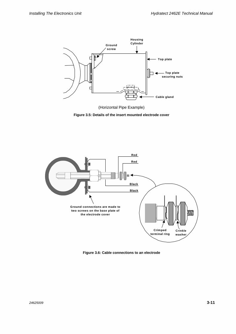
terminations for the electronics unit end of the cable 2 Remove the top plate securing nuts from the electrode cover (shown in Figure 3.5) and
then remove the top plate from the housing cylinder 3 Feed the cable through the cable gland, from inside the housing cylinder. Leave about
200mm of cable (with the crimped terminal rings) protruding from the end of housing cylinder
4 On the electrode cover base plate, connect the ground and ground-sense conductors
(black), separately, to the two ground screws. (See Figure 3.6)
5 Draw sufficient cable through the cable gland to allow the housing cylinder to be re-seated on the base plate
6 On the electrode, secure each conductor (red) under a crinkle washer and a knurled nut. (This can be seen in Figure 3.6.) Ensure that there is a stress-free run of cable inside the electrode cover and ensure that the cable gland is oriented correctly. (If necessary, cut back to the cable cover, including the screening foil and screen wire, to achieve this.) Note: The cable screen must not be connected to ground at the electrode end of the cable
7 Replace the top plate of the electrode cover and fit the top plate securing nuts. Coat the
threads with high temperature, anti-seize compound 8 Tighten the cable gland.
Installing The Electronics Unit Hydratect 2462E Technical Manual
24625009 3-11
Groundscrew
Top plate
HousingCylinder
Top platesecuring nuts
Cable gland
(Horizontal Pipe Example)
Figure 3.5: Details of the insert mounted electrode cover
Red
Red
Black
Black
Crimpedterminal ring
Crinklewasher
Ground connections are made totwo screws on the base plate of
the electrode cover
Figure 3.6: Cable connections to an electrode

Hydratect 2462E Technical Manual Installing The Electronics Unit
3-12 24625009
3.5.1.2 PREPARING AN ELECTRODE CABLE FOR CONNECTION TO THE ELECTRONICS UNIT
This following procedure assumes that the electrode cable has already been connected to the electrode as described in Section 3.5.1.1:
1 If the front panel of the 2462 Electronic Unit is presently fitted to the case, remove the panel from the case and store it in a safe place. (This is described in more detail on page 3-4)
(The panel has mounted on it all the electronic circuitry and must be protected against adverse conditions such as heat, dust and static electricity).
2 Route the cable from the electrode, through suitable ducting, to the 2462 Electronics Unit.
3 Assemble the cable gland, as described in the manufacturer’s instructions, and fit it to the underside of the electronics unit. Allow for cable conductors of length 300mm inside the unit
Note:
The electrode cable has an aluminium foil screen, which must be grounded to the cable gland on the unit. Connection is made through the standard ‘drain’ wire that runs the full length of the cable and makes good contact with the screen. An effective seal against electromagnetic interference is made with good annular (ring shaped) contact with the RF cable gland. Trim the insulation to leave about 20mm of metal foil exposed, which can be folded back over the insulation. Make sure this foil cover is the part clamped by the screen of the gland when it is tightened. Be careful not to damage the ‘drain’ wire, which can be clamped as you would do for a braided screen.
4 Slide a ferrite (supplied) over the cables inside the unit and fix it tight against the gland input. Prepare the electrode cable for fitting to an 8-way Klippon connector, by stripping the end of each conductor and crimping on the pins required. (Remove only sufficient insulation to ensure good contact: the stripped end must be fully inserted into the pin).
Note:
It is considered good practise to twist the electrode pairs together, and twist all the pairs from one cable into a neat harness within the unit.
5 Fit the electrode cable to the 8-way Klippon connector by screwing in the crimped-on pins as shown Figure 3.7.
Note: It is unimportant which way round paired conductors, e.g. red and red, are connected.
6 Repeat steps 2 to 5 for the second channel
The electrode cables are now ready for connection to the electronic unit front panel. However, you will probably find it easier to first prepare the fault/status cables and the power cables before connecting the others to the front panel.
R R Bk Bk
(R = Red) (Bk = Black)
1 2 3 4 5 6 7 8
Connector onHydratect 2462Front Panel PCB
Termination screwsare on this side
Connector onelectrode cable
PL205 (Channel 1)PL405 (Channel 2)
Figure 3.7: Fitting the electrode cable to the 8-way connector

Installing The Electronics Unit Hydratect 2462E Technical Manual
24625009 3-13
3.5.2 PREPARING THE FAULT/STATUS RELAY CABLES
The electronics unit uses normally-open and normally-closed switch outputs for fault and status indication. The outputs are available on a pair of 10-way Klippon connectors: PL204 and PL404. The procedure for making connections to the switched outputs is: 1 If the front panel of the 2462 Electronics Unit is presently fitted to the case, remove the front
panel from the case and store it in a safe place. (This is described in detail on page 3-4)
(The panel has mounted on it all the electronic circuitry and must be protected against adverse conditions such as heat, dust and static electricity)
2 Route the fault/status cable from the external equipment, through suitable ducting, to the
2462 Electronics Unit
3 Assemble the cable gland as described in the manufacturer’s instructions, and fit it to the underside of the electronics unit.
Screened cables must be used. Ensure there is a good annular (ring shaped) contact between the cable screen and cable gland. Allow for cable conductors of length 300mm inside the unit, and twist the power pairs together. The Fault/Status cable should not be shared with Electrode or Power wires in the same cable
4 Prepare the electrode cable for fitting to the Klippon connector, by stripping the end of each
conductor and crimping on the pins required. (Remove only sufficient insulation to ensure good contact: the stripped end must be fully inserted into the pin)
5 Fit the cable to a Klippon connector by screwing in the crimped-on pins, in accordance with
Figure 3.8. 6 Repeat steps 2 to 4 for the second channel The fault/status cables are now ready for connection to the front panel of the electronics unit. Remember, however, that it is easier to prepare all the cables before connecting them to the front panel.

Hydratect 2462E Technical Manual Installing The Electronics Unit
3-14 24625009
Red
Red
Black
Black
1 2 3 4 5 6 7 8
PL205 (405)
Red Black
PL203 (403)PL206 (406)
1
2
3
LIVE
NEUTRAL
PL101 (301)
CHANNEL 1 (2)
PL204 (404)
AC SUPPLY230V
1 2 3 4 5 6 7 8 9 10 11 12 13 14
N.O.FAULT
FAULT
STATUS
STATUS
LATCHING RESET
4-core PTFE cablesupplied with system
N.C.C.
N.C.
N.O.C.
N.O.
N.C.C.
N.C.
N.O.C.
Figure 3.8: Status, fault and status latching reset connections
Notes: 1. The relays are energised under normal
conditions. (On this diagram, they are shown de-energised.)
2. The option Jumpers are shown in their
default configuration. For the various options, refer to Table 3.1 on page 3-7.
3. There is no internal ground connection.
Connect the 2462 case to ground from the M6 Ground Stud. (See Section 3.3 on page 3-5.)
4. The relay ratings are 8A at 250Vac and
0.25A at 220Vdc.

Installing The Electronics Unit Hydratect 2462E Technical Manual
24625009 3-15
3.5.3 PREPARING THE POWER SUPPLY CABLES
Each channel has an independent power supply input, that can receive power from a 230V ac or 115V ac sources:
The connections for these power supplies are shown in Figure 3.9. Connector locations are shown in Figure 3.10 on page 3-16.
1
2
3
Connector on power supply PCB:PL101 (Channel 1)PL301 (Channel 2)
L
Not Connected
N
230V AC
L
Not Connected
N
115V AC
Power Connector
Shroud half-shellCable clamp
Figure 3.9: Power supply connections
The connection procedure is:
1 If the front panel of the 2462 Electronics Unit is presently fitted to the case, remove the front panel from the case and store it in a safe place. (This is described in detail on page 3-4)
(The panel has mounted on it all the electronic circuitry and must be protected against adverse conditions such as heat, dust and static electricity)
2 Route the power cable from the external supply, through suitable ducting, to the 2462 Electronics Unit
3 Assemble the cable gland as described in the manufacturer’s instructions, and fit it to the underside of the electronics unit. Screened cables and RF cable glands to EN61010, clause 6.10.2.2 must be used. Ensure there is a good annular (ring shaped) contact between the cable screen and cable gland. Allow for cable lengths of 300mm inside the unit. Twist the power pairs together and fit a second insulating sleeve over the wires. The Power wires must not be shared with signal wires in the same cable
4 Prepare the power cable for fitting to a 3-way power connector, by cutting back 20mm of outer insulating cover, stripping the end of each conductor and crimping on the pins provided. (Remove only sufficient insulation to ensure good contact: the stripped end must be fully inserted into the pin)
5 Fit the cable to a 3-way power connector by screwing in the crimped-on pins, in accordance with Figure 3.9
6 Now fit the power connector shroud, securing the cable outer insulation with the shroud cable clamp
7 Repeat steps 2 to 6 for the second channel
Hydratect 2462E Technical Manual Installing The Electronics Unit
3-16 24625009
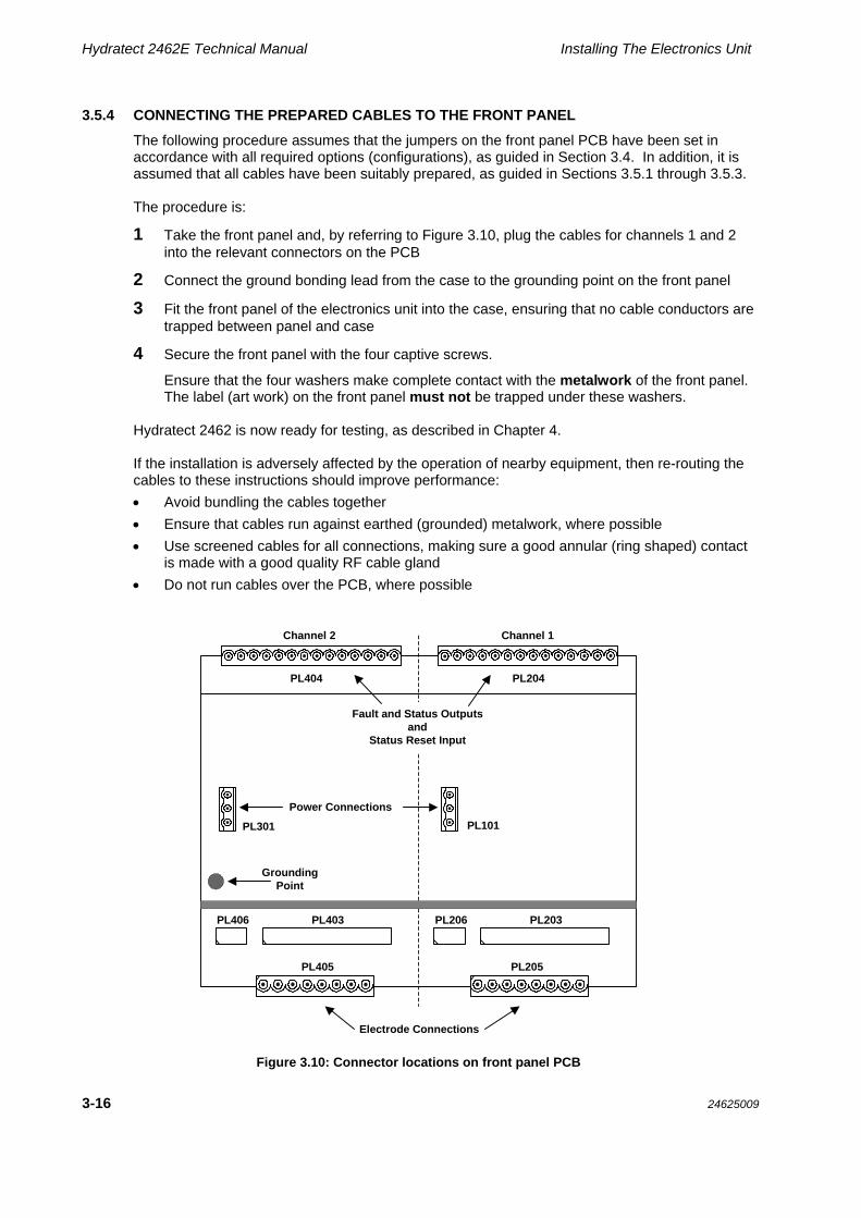
3.5.4 CONNECTING THE PREPARED CABLES TO THE FRONT PANEL
The following procedure assumes that the jumpers on the front panel PCB have been set in accordance with all required options (configurations), as guided in Section 3.4. In addition, it is assumed that all cables have been suitably prepared, as guided in Sections 3.5.1 through 3.5.3. The procedure is:
1 Take the front panel and, by referring to Figure 3.10, plug the cables for channels 1 and 2 into the relevant connectors on the PCB
2 Connect the ground bonding lead from the case to the grounding point on the front panel
3 Fit the front panel of the electronics unit into the case, ensuring that no cable conductors are trapped between panel and case
4 Secure the front panel with the four captive screws.
Ensure that the four washers make complete contact with the metalwork of the front panel. The label (art work) on the front panel must not be trapped under these washers.
Hydratect 2462 is now ready for testing, as described in Chapter 4. If the installation is adversely affected by the operation of nearby equipment, then re-routing the cables to these instructions should improve performance:
Avoid bundling the cables together
Ensure that cables run against earthed (grounded) metalwork, where possible
Use screened cables for all connections, making sure a good annular (ring shaped) contact is made with a good quality RF cable gland
Do not run cables over the PCB, where possible
PL404
Channel 2 Channel 1
PL204
PL403PL406
PL405 PL205
Power Connections
PL203PL206
PL301 PL101
Fault and Status Outputs and
Status Reset Input
Electrode Connections
GroundingPoint
Figure 3.10: Connector locations on front panel PCB

Hydratect 2462E Technical Manual
24625009 4-1
4
Testing the 2462
Contents
4.1 TEST SUMMARY ........................................................................................................................... 4-2
4.2 ELECTRODE TESTING ................................................................................................................ 4-3
4.2.1 Water-normal procedure ................................................................................................... 4-3 4.2.2 Steam-normal procedure ................................................................................................... 4-5

Hydratect 2462E Technical Manual Testing the 2462
4-2 24625009
4.1 TEST SUMMARY
This Chapter contains the confidence checkout procedures for the two basic configurations of the Hydratect 2462 system: (1) water-normal and (2) steam-normal Use the relevant procedure to check out the operation of the Hydratect 2462 system, following installation completion or any change to the configuration. In each procedure, provision is made for checking the various detection sensitivities and the latched fault relay facility. The test equipment required is minimal and depends to some extent on the ancillary equipment installed in your system. You will need: A resistor to simulate water presence
– 56k (low sensitivity),
– 120k (high sensitivity).
A resistor to simulate electrode contamination
– 270 (low sensitivity),
– 820 (high sensitivity).
A fault relay reset push-button. (Required only when the latched relay option is configured)
A device, such as a lamp or beeper. This is to check the operation of the output contacts. The contact ratings are given the Hydratect 2462 specification at the end of Chapter 1. Where ancillary equipment is already connected to the output contacts, and may safely be used, it may be more appropriate to check the contact operation with that equipment.

Testing the 2462 Hydratect 2462E Technical Manual
24625009 4-3
4.2 ELECTRODE TESTING
4.2.1 WATER-NORMAL PROCEDURE
1 Switch on the power supply to the Hydratect 2462 electronics unit
2 Check the front panel LEDs are as expected:
! Off
STEAM On
WATER Off
3 Check the relays are as expected:
Fault Energised
Electrode status De-energised
4 To simulate the electrode in water, remove the electrode cover and short the sense element
terminal to ground through a 120k resistor (high sensitivity) or a 56k resistor (low sensitivity)
5 Check the front panel LEDs are as expected:
! Off
STEAM Off
WATER On
6 Check the relays are as expected:
Fault Energised
Electrode status Energised
7 Remove the resistor and check that the LEDs an relays have resumed their original states
(as shown in steps 2 and 3)
8 To simulate electrode contamination, short the sense element terminal to ground through an
820 resistor (high sensitivity) or a 270 resistor (low sensitivity)
9 Check the front panel LEDs are as expected:
! On
STEAM Off
WATER On
10 Check on the relays are as expected:
Fault De-energised
Electrode status Energised
Hydratect 2462E Technical Manual Testing the 2462
4-4 24625009
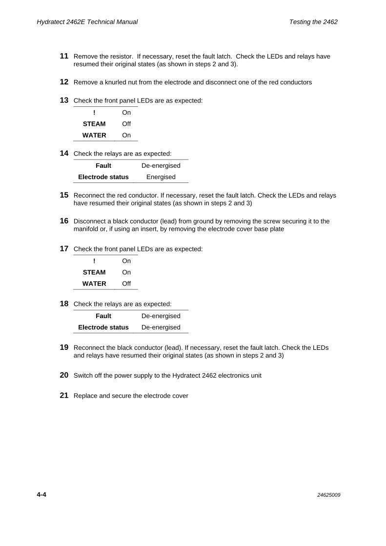
11 Remove the resistor. If necessary, reset the fault latch. Check the LEDs and relays have resumed their original states (as shown in steps 2 and 3).
12 Remove a knurled nut from the electrode and disconnect one of the red conductors
13 Check the front panel LEDs are as expected:
! On
STEAM Off
WATER On
14 Check the relays are as expected:
Fault De-energised
Electrode status Energised
15 Reconnect the red conductor. If necessary, reset the fault latch. Check the LEDs and relays
have resumed their original states (as shown in steps 2 and 3)
16 Disconnect a black conductor (lead) from ground by removing the screw securing it to the
manifold or, if using an insert, by removing the electrode cover base plate
17 Check the front panel LEDs are as expected:
! On
STEAM On
WATER Off
18 Check the relays are as expected:
Fault De-energised
Electrode status De-energised
19 Reconnect the black conductor (lead). If necessary, reset the fault latch. Check the LEDs and relays have resumed their original states (as shown in steps 2 and 3)
20 Switch off the power supply to the Hydratect 2462 electronics unit
21 Replace and secure the electrode cover

Testing the 2462 Hydratect 2462E Technical Manual
24625009 4-5
4.2.2 STEAM-NORMAL PROCEDURE
1 Switch on the power supply to the Hydratect 2462 electronics unit
2 Check the front panel LEDs are as expected:
! Off
STEAM On
WATER Off
3 Check the relays are as expected:
Fault Energised
Electrode status Energised
4 To simulate the electrode in steam, remove the electrode cover and short the sense
element terminal to ground through a 120k resistor (high sensitivity) or a 56k resistor (low sensitivity)
5 Check the front panel LEDs are as expected:
! Off
STEAM Off
WATER On
6 Check the relays are as expected:
Fault Energised
Electrode status De-energised
7 Remove the resistor and check that the LEDs an relays have resumed their original states
(as shown in steps 2 and 3)
8 To simulate electrode contamination, short the sense element terminal to ground through an
820 resistor (high sensitivity) or a 270 resistor (low sensitivity)
9 Check the front panel LEDs are as expected:
! On
STEAM Off
WATER On
10 Check on the relays are as expected:
Fault De-energised
Electrode status De-energised
11 Remove the resistor. If necessary, reset the fault latch. Check the LEDs and relays have
resumed their original states (as shown in steps 2 and 3).

Hydratect 2462E Technical Manual Testing the 2462
4-6 24625009
12 Remove a knurled nut from the electrode and disconnect one of the red conductors
13 Check the front panel LEDs are as expected:
! On
STEAM Off
WATER On
14 Check the relays are as expected:
Fault De-energised
Electrode status De-energised
15 Reconnect the red conductor. If necessary, reset the fault latch. Check the LEDs and relays
have resumed their original states (as shown in steps 2 and 3)
16 Disconnect a black conductor (lead) from ground by removing the screw securing it to the
manifold or, if using an insert, by removing the electrode cover base plate
17 Check the front panel LEDs are as expected:
! On
STEAM On
WATER Off
18 Check the relays are as expected:
Fault De-energised
Electrode status De-energised
19 Reconnect the black conductor (lead). If necessary, reset the fault latch. Check the LEDs and relays have resumed their original states (as shown in steps 2 and 3)
20 Switch off the power supply to the Hydratect 2462 electronics unit
21 Replace and secure the electrode cover

Hydratect 2462E Technical Manual
24625009 5-1
5
Servicing the Electrodes
Contents
5.1 SERVICE SUMMARY .................................................................................................................... 5-2
5.1.1 Safety precautions .............................................................................................................. 5-2
5.2 PERIODIC CHECK ........................................................................................................................ 5-3
5.3 REPAIRING AN ELECTRODE ...................................................................................................... 5-4
5.4 PERIODIC SYSTEM OVERHAUL ................................................................................................. 5-6
5.5 ELECTRODE REPLACEMENT PARTS ....................................................................................... 5-6

Hydratect 2462E Technical Manual Servicing the Electrodes
5-2 24625009
5.1 SERVICE SUMMARY
This Chapter describes the servicing procedure that must be followed to ensure continued and trouble-free operation of the Hydratect 2462 system. Electrodes should be examined periodically, as described in Section 5.2, to ensure that each one is fully serviceable. Faults discovered during a periodic check must be repaired in accordance with the procedure described in Section 5.3.
All servicing work must be done in accordance with the safety precautions listed in Section 5.1.1.
To avoid extended system downtime, it is wise to ensure the immediate availability of all spares listed in Section 5.5 of this Chapter. (Turn to page 5-6)
5.1.1 SAFETY PRECAUTIONS
The following safety procedures must be observed for all service work: Electrodes must be serviced strictly in accordance with site practices
Where it is customary, obtain a valid ‘permit to work’ before starting the service
Ensure that any tripping action likely to occur is inhibited
Where automatic control actions could be initiated, these actions must be inhibited outside the Hydratect 2462 system before starting the service
Advise the operators of any unusual effects likely to occur during the service
Where operator warning alarms are fitted, the operator(s) must be informed which alarms will be affected and for how long
Ensure that you know the correct procedures before starting the service
Wear industrial gloves when working on the electrodes and associated fittings.

Servicing The Electrodes Hydratect 2462E Technical Manual
24625009 5-3
5.2 PERIODIC CHECK
A periodic check should be made (monthly, for example) to ensure that the electrodes, manifolds and cables are in a serviceable state. This examination should reveal any faults that are obvious from the electrode exterior. Faults must be repaired as described in Section 5.3. The state of the electrode insulator within the pipe is monitored continuously by the 2462 electronics unit. Whenever the insulator becomes contaminated, the alarm LED is illuminated and the alarm output is switched to the fail-safe (alarm) state. The electrode must then be cleaned, as described in Section 5.3. The recommended procedure for a periodic check is: 1 Inspect the electrode covers and cables. Any damaged item must be removed and a
serviceable replacement part fitted. Standard replacement parts are listed in Section 5.5 2 Loosen the cable glands on the electrode covers. Remove screws securing the cover and
then ease the cover away from the manifold (or insert). This will expose the electrode 3 Remove the accumulation of dust with a soft brush 4 Inspect the electrode(s) for correct sealing and freedom from damage. An electrode
fault, such as a leaking seal or damage to the electrode, must be repaired as described in Section 5.3.
A faulty seal is indicated by wisps of steam, which appears to come from the external ceramic insulator (of the electrode) or from the electrode nut. Steam will always tend to emanate from a leak, even if the electrode is immersed in water. This is due to the temperature in a pressurised system causing water to flash-off to steam as it reaches ambient pressure
5 Check the electrode connections are in good condition and are tightly secured. Tighten
any loose connection 6 Having ensured that the electrode, electrode mounting and electrode cables are in a
serviceable condition, re-fit and secure the electrode cover 7 Tighten the electrode cable glands This periodic check is now complete.

Hydratect 2462E Technical Manual Servicing the Electrodes
5-4 24625009
5.3 REPAIRING AN ELECTRODE
An electrode must be removed for repair or replacement if it has any of the following faults:
(a) a contaminated insulator,
(b) a defective seal,
(c) mechanical damage.
Note:
To ensure that electrodes fitted to multiple-port manifold are reconnected correctly after service, complete work on one electrode before moving on to the next.
Caution:
Do not attempt to cure a defective seal simply by tightening the electrode nut.
The procedure for repairing is:
1 Isolate and drain the pipe on which the electrode is mounted, following the safetyprecautions listed in Section 5.1.1 of this Chapter
2 Loosen the electrode cable glands (if applicable) and remove the electrode cover
3 Disconnect conductors (leads) from the electrode, undo the electrode nut, and carefullyremove the electrode from the port
4 Ensure the electrode port bore is free of loose particles
5 Check the seating face of the port. A scored or eroded seating face can be re-cut to anacceptable standard using the appropriate service tool listed below.
Service Tool 246791AA – for use with electrodes 246785A and 246785Z only Service Tool 246722AA – for use with electrode 246785P only
6 If there is obvious damage to the electrode, replace it with a new electrode:
(a) Carefully remove new electrode from the packaging and check it is undamaged.
(In the event of discovering any damage, contact your Rosemount Measurement agent for replacement of the defective item)
(b) Proceed to step 8
7 If there is obvious contamination and/or a defective seal:
(a) Examine the seating surface of the electrode, to ensure that it is clean and free from surface deterioration.
If the electrode is able to perform an effective seal then it can be used again. However, to ensure absolute cleanliness, wipe the internal insulator (of the electrode) with a clean cloth.
Alternatively, if the seating surface is eroded, or if there is a possibility of a leak through the external insulator, replace it with a new electrode – return to step 6(a).

Servicing The Electrodes Hydratect 2462E Technical Manual
24625009 5-5
8 Clean the threads of a port, prior to fitting an electrode
9 To alleviate thread seizure problems, lightly coat the thread of the insert with anti-seizecompound (Rosemount Measurement part number 830007220)
10 Ease the electrode into the insert and then turn the fixing nut of the electrode, clockwise,with your fingers to engage the threads
11 Using a long-reach 25mm AF socket spanner, gradually tighten the electrode fixing nut untilthe electrode will not rotate in its’ seat
12 Finally, tighten the electrode nut a further 1/8th to ¼ turn to complete the procedure.
13 Re-connect conductors (leads) to the electrode
14 Repeat steps 3 to 13 for any other electrode in need of repair or replacement
15 Replace the electrode cover and secure
16 If applicable, tighten the electrode cable glands
This completes the procedure.
High Pressure Electrode Note: The final 1/8th to ¼ turn corresponds to a torque level of between 28lbft (35Nm) and 47lbft (60Nm). The 1/8th turn is the recommended tightening condition, ¼ is the maximum allowable, and the tightening torque used must be the minimum to achieve this. Failure to comply with this limitation may cause damage to the port or to the electrode from over tightening.

Hydratect 2462E Technical Manual Servicing the Electrodes
5-6 24625009
5.4 PERIODIC SYSTEM OVERHAUL
During a system overhaul, Hydratect must be protected against mechanical damage. Protection can be afforded by any rigid material, such as packing cases, that can be lashed into place to prevent impact damage. When the system overhaul is complete, remove the protective material and use the periodic check procedure (on page 5-3) to verify the correct operation of Hydratect.
5.5 ELECTRODE REPLACEMENT PARTS
The electrode replacement parts listed here should be readily available, on site, whenever a periodic check takes place or electrode repairs are made. Spare electrodes, according to the type installed – See Chapter 2 for part numbers Spare electrode cables, according to the type installed – See Chapter 3 for part numbers

Hydratect 2462E Technical Manual
24625009 6-1
6
Servicing the Electronics
Contents
6.1 FAULT DIAGNOSIS ...................................................................................................................... 6-2
6.2 CORRECTING A FAULT ............................................................................................................... 6-3
6.2.1 Correcting a power supply loss ......................................................................................... 6-3 6.2.2 Correcting electrode connection faults .............................................................................. 6-4
6.3 ELECTRODE CONTAMINATION ................................................................................................. 6-5
6.4 ELECTRONIC COMPONENT FAILURE ....................................................................................... 6-5
6.5 ELECTRONICS REPLACEMENT PARTS .................................................................................... 6-5
List of Tables TABLE 6.1: WATER-NORMAL FAULTS AND FAULT SYMPTOMS ....................................................... 6-2
TABLE 6.2: STEAM-NORMAL FAULTS AND FAULT SYMPTOMS ....................................................... 6-2
TABLE 6.3: TEST POINT VALUES .......................................................................................................... 6-2

Hydratect 2462E Technical Manual Servicing the Electronics
6-2 24625009
6.1 FAULT DIAGNOSIS
Any electrical or electronic faults that may occur in Hydratect 2462 are indicated both by the LEDs on the electronics unit (front panel) and by the fault and status output. Table 6.1 and Table 6.2 are lists of faults and fault symptoms that can be diagnosed from these indications. Table 6.3 lists the test point values that should be present on a serviceable logic card (24620504). The test points are located on PL206 (Hydratect Channel 1) and PL406 (Hydratect Channel 2). If any of the values measured on this card are markedly different from those shown in the table then the card is not functioning correctly.
Table 6.1: Water-normal faults and fault symptoms
Fault Summary Front Panel LEDs Output Relays
! Steam Water Fault Status Normal
Power supply loss Off Off Off De-energised De-energised
Electrode contaminated or short-circuited On Off On De-energised Energised
Connection to electrode sense element is broken On Off On De-energised Energised
Connection to electrode ground is broken On Off On De-energised Energised
Connection to ground sense is broken – electrode in water On Off On De-energised Energised
Connection to ground sense is broken – electrode in steam On On Off De-energised De-energised
Table 6.2: Steam-normal faults and fault symptoms
Fault Summary Front Panel LEDs Output Relays
! Steam Water Fault Status Normal
Power supply loss Off Off Off De-energised De-energised
Electrode contaminated or short-circuited On Off On De-energised De-energised
Connection to electrode sense element is broken On Off On De-energised De-energised
Connection to electrode ground is broken On Off On De-energised De-energised
Connection to ground sense is broken – electrode in water On Off On De-energised De-Energised
Connection to ground sense is broken – electrode in steam On On Off De-energised Energised
Table 6.3: Test Point Values
Test Points
PL206 (Channel 1)
PL406 (Channel 2)
Pin No. Normal State
1 -6.0V
2 -5.4V Water-normal, low sensitivity: 20Hz. -6V to +3.1V
3 0V Water-normal, high sensitivity: 20Hz, -6V to +4.1V
4 20Hz, 6V Steam-normal, low sensitivity: +3.1V
5 Status ref. Steam-normal, high sensitivity: +4.1V
6 -5.7V
7 Error ref. Low sensitivity: +41mV
8 20Hz, 6V High sensitivity: +120mV
9 +5.7V
10 +6.0V

Servicing The Electronics Hydratect 2462E Technical Manual
24625009 6-3
6.2 CORRECTING A FAULT
Correcting a Hydratect electrical or electronic fault on site is limited to making good any faulty electrode connections or replacing a faulty card.
The action to take for the faults listed in Table 6.1 and Table 6.2 are described in Sections 6.2.1 through Y.
6.2.1 CORRECTING A POWER SUPPLY LOSS
The procedure is:
1 Check that external power is being applied to Hydratect. If it is not, reinstate the supply
2 If Hydratect is receiving power but indicating a power loss the possible is:
(a) the power supply card (24620503B) is faulty,
(b) the logic card (24620504A) has a fault that is dragging down the output of the power supply card
3 Switch off the external power supplies to Hydratect
4 Undo the two screws securing the front panel of the electronics unit and carefully withdrawthe panel from the case
5 Remove the connectors from the power supply and from the logic card
6 Remove the power supply card and the logic card
7 Return the power supply card and logic cards to your Rosemount Measurement agent for servicing
9 Re-fit the connectors to the power supply and logic cards, ensuring the connections aremade correctly to each channel
10 Switch on the external supplies to the Hydratect and check the system out, as described inChapter 4.
8 Fit a new logic card and a new power supply card, securing these with the threaded pillars
and screws removed in step 5

Hydratect 2462E Technical Manual Servicing the Electronics
6-4 24625009
6.2.2 CORRECTING ELECTRODE CONNECTION FAULTS
Most electrode connection faults (faults 2 through 6 in Table 6.1 and Table 6.2) may be cured by the following procedure: 1 Switch off the external power supplies to the Hydratect electronics unit 2 Loosen the cable glands on the electrode cover 3 Draw back the cable cover to reveal the electrode connections 4 Check the cable connections 5 Tighten any connection that is loose. Re-connect any lead that has broken off. Remember
that all connections to the electrode must be made individually. Do not twist any two (or more) wires together. The ground and ground sense, for example, must be made to separate ground screws
6 Replace the cable cover and secure 7 Tighten the cable glands 8 Switch on the external power supplies to the electronics unit. Check out the system
operation 9 If there is still a connection fault, switch off the external power supplies 10 Undo the two screws securing the front panel of the electronics unit and carefully withdraw
the panel from the case 11 Check the electrode connections to the logic card 12 Tighten any loose connections and remake any broken connection 13 Replace and secure the front panel 14 Switch on the external power supplies to the electronics unit. Check the system operation 15 If there is still a connection fault it must be located in the cable itself. Switch off the external
power supplies 16 Remove the faulty electrode cable and connect a new one, as described in Chapter 3 17 Switch on the external power supplies to the electronics unit. Check the system operation.
There should be no further problem.

Servicing The Electronics Hydratect 2462E Technical Manual
24625009 6-5
6.3 ELECTRODE CONTAMINATION
A contaminated electrode – fault 2 in Table 6.1 and Table 6.2 – may be cleaned as described in Chapter 5. Look for the repair procedure.
6.4 ELECTRONIC COMPONENT FAILURE
On site, an electronic component failure can be cured only by removing the logic card and fitting a new card.
The procedure is:
1 Switch off the external power supplies to the Hydratect
2 Undo the two screws securing the front panel of the electronics unit and carefully withdrawthe panel from the case
3 Remove the connectors from the power supply and from the logic card
4 Remove the power supply card and the logic card. Five screws and five threaded pillarsmust be removed to do this
5 Return the logic card to your Rosemount Measurement agent for servicing
6 Fit a new logic card and the original power supply card, securing these with the threadedpillars and screws removed in step 4
7 Re-fit the connectors to the power supply and logic cards, ensuring the connections aremade correctly to each channel
8 Switch on the external supplies to the Hydratect and check the system out, as described inChapter 4.
6.5 ELECTRONICS REPLACEMENT PARTS
The following replacement parts should be readily available, on site, for use in case of an electronics failure:
Spare PCBs:
- power supply ac ( 24620503B)
- logic – relay output (24620504A)
Spare cables, according to cables installed – See Chapter 3 for part numbers.

Hydratect 2462E Technical Manual Servicing the Electronics
6-6 24625009


Hydratect 2462ETechnical Manual
24625009, Rev. ACJune 2011
The Emerson logo is a trade mark and service mark of Emerson Electric Co. Mobrey is a registered trademark of Rosemount Measurement Ltd. All other marks are the property of their respective owners. We reserve the right to modify or improve the designs or specifications of product and services at any time without notice.
© 2011 Rosemount Measurement Ltd. All rights reserved.
International: Emerson Process Management Rosemount Measurement Ltd. 158 Edinburgh Avenue, Slough, Berks, SL1 4UE, UK T +44 1753 756600 F +44 1753 823589 www.emersonprocess.com