k40 laser cutterfloatingwombat.me.uk/.../2015/02/k40-alignment-instructions.pdf · k40 alignment...
TRANSCRIPT
K40 Laser Cutter
Alignment Instructions
Dr T.J. Fawcett
V1.00 Jan 2015
© T.J. Fawcett – you are free to copy this but please acknowledge
me when you use it and let me know by e-mail.

Table Of Contents
i
Introduction...................................................................................................... 2
Adjusting the Mirrors ...................................................................................... 3
Alignment Procedure ..................................................................................... 5
Preparing for Alignment ................................................................................ 6
Positioning the Fixed Mirror .......................................................................... 8
Aligning the Fixed Mirror ................................................................................ 9
Positioning the Y Axis Mirror ....................................................................... 12
Aligning the Y Axis Mirror ............................................................................ 14
Aligning the Lens Holder .............................................................................. 15

K40 Alignment Instructions
2
Introduction
To get the best performance (or indeed any performance) from
the cutter it is necessary to ensure the light path from the laser
to the work piece is correctly aligned. My unit was supplied
without the light path setup – in the end I had to modify the
cutter to get a good alignment. Even now it is not perfect but it is
pretty good.
To perform the alignment the following things are required:
• Meths (or acetone or Iso-propyl Alcohol) for cleaning the
lens
• Kitchen roll for lens cleaning
• Masking tape for the alignment
• Spanner for the lock nuts
• Time – lots of time – 2 to 3 hours
• Patience
• More time & patience
• Several attempts
The light path of the laser cutter is:
Laser
Fixed Mirror
Y Stage Mirror
X Stage Mirror & Lens
K40 Alignment Instructions
3
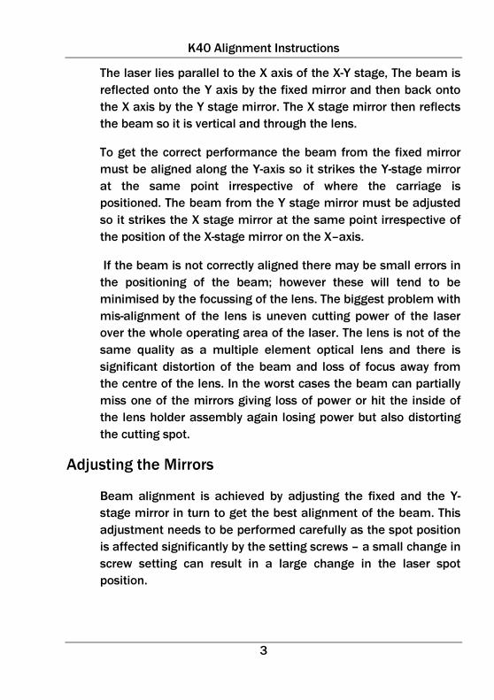
The laser lies parallel to the X axis of the X-Y stage, The beam is
reflected onto the Y axis by the fixed mirror and then back onto
the X axis by the Y stage mirror. The X stage mirror then reflects
the beam so it is vertical and through the lens.
To get the correct performance the beam from the fixed mirror
must be aligned along the Y-axis so it strikes the Y-stage mirror
at the same point irrespective of where the carriage is
positioned. The beam from the Y stage mirror must be adjusted
so it strikes the X stage mirror at the same point irrespective of
the position of the X-stage mirror on the X–axis.
If the beam is not correctly aligned there may be small errors in
the positioning of the beam; however these will tend to be
minimised by the focussing of the lens. The biggest problem with
mis-alignment of the lens is uneven cutting power of the laser
over the whole operating area of the laser. The lens is not of the
same quality as a multiple element optical lens and there is
significant distortion of the beam and loss of focus away from
the centre of the lens. In the worst cases the beam can partially
miss one of the mirrors giving loss of power or hit the inside of
the lens holder assembly again losing power but also distorting
the cutting spot.
Adjusting the Mirrors
Beam alignment is achieved by adjusting the fixed and the Y-
stage mirror in turn to get the best alignment of the beam. This
adjustment needs to be performed carefully as the spot position
is affected significantly by the setting screws – a small change in
screw setting can result in a large change in the laser spot
position.
K40 Alignment Instructions
4
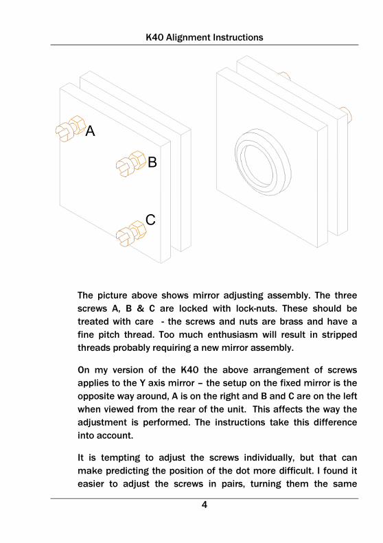
The picture above shows mirror adjusting assembly. The three
screws A, B & C are locked with lock-nuts. These should be
treated with care - the screws and nuts are brass and have a
fine pitch thread. Too much enthusiasm will result in stripped
threads probably requiring a new mirror assembly.
On my version of the K40 the above arrangement of screws
applies to the Y axis mirror – the setup on the fixed mirror is the
opposite way around, A is on the right and B and C are on the left
when viewed from the rear of the unit. This affects the way the
adjustment is performed. The instructions take this difference
into account.
It is tempting to adjust the screws individually, but that can
make predicting the position of the dot more difficult. I found it
easier to adjust the screws in pairs, turning them the same

K40 Alignment Instructions
5
amount: adjusting A & B together moves the position of the spot
up or down, keeping it in the same left-right position; adjusting B
& C together moves the position of the spot left to right keeping
the same up-down position. Adjusting an individual screw will
move the spot by some arbitrary and possibly unpredictable
angle which will mean alignment will take longer to complete.
Before starting adjustment, release all three locknuts on the
mirror so the screws can turn freely. Once alignment is
completed, tighten the nuts up without changing the position of
the screws otherwise adjustment will have to start all over again.
Alignment Procedure
The alignment procedure is divided up into phases – each one
should be completed fully before moving onto the next one. The
steps should be performed in the sequence below:
1. Preparing for the Alignment
2. Positioning the Fixed Mirror
3. Aligning the Fixed Mirror
4. Positioning the Y axis Mirror
5. Aligning the Y axis Mirror
6. Positioning the Lens Holder
7. Aligning the Lens Holder
8. Completing Alignment
K40 Alignment Instructions
6
Preparing for Alignment
The first stage of the alignment process is to get the machine
ready for the process. With the unit powered off, remove the
laser tube cover and the front door. If you have been sensible
and installed interlocks on the cover and door these will need to
be overridden to allow the laser to be fired.
WARNING
Performing the alignment process leaves the laser
beam exposed. Please follow these safety rules:
Keep all other people away from the cutter while
performing the alignment
Wear laser safety glasses if you have them.
Look away from the beam and close your eyes
when firing the beam
Keep your hands out of the beam – even the
unfocussed beam can cause third degree burns.
You are responsible for your own safety and any
damage you cause yourself, the laser cutter or
anything or anyone else. Treat the equipment with
respect.

K40 Alignment Instructions
7
The cooling water system needs to be running as the laser will
be activated. Place a piece of masking tape over the fixed mirror
as shown below:
Turn the laser power control down to minimum. Press the laser
fire button; there should be no reading on the meter. Turn the
power control up and perform a test fire using the fire button.
Repeat this until the system starts to register current on the
meter. On my cutter this happens at about 5mA. This is the point
where the laser just starts to lase. Doing this should allow you to
burn a small spot in the masking tape without blowing a hole
through it or setting it on fire. It may require the button to be
held for a couple of seconds to get a good spot – practice shows
how long you need for your masking tape and laser.

K40 Alignment Instructions
8
This shows the sort of spot you can achieve – this is a
reasonable size for aligning the mirrors.
If you are still using Moshidraw run it on the computer and
connect the computer to the cutter. Select the “Output to Laser”
option and when the dialogue box is displayed click the “Free
Motor” button. This disengages the motor drives so the carriage
can be easily slid around. If you have upgraded the controller,
use the equivalent command or disconnect the stepper motors.
Positioning the Fixed Mirror
Note: This stage is normally only required when the cutter is
being first setup or the laser tube has been changed or
repositioned.
The first stage of the alignment process is to adjust the position
of the fixed mirror. Put a new piece of tape over the mirror and
fire the laser. The spot should be in the middle of the mirror. If

K40 Alignment Instructions
9
the spot is to one side or the other the mirror can be slid back or
forward by loosening its fixing screws. If the mirror is too low it
can be packed to raise it up. If it is too high, the only option is to
adjust the rubber on the laser tube to lower it. Once the spot is in
the centre of the mirror, the mirror is positioned correctly.
Once the mirror is positioned, ensure all the screws are
tightened, remove the masking tape and clean the mirror to
remove the burnt residue of masking tape.
Aligning the Fixed Mirror
To align the fixed mirror, put tape over the Y-axis mirror and slide
the carriage so the mirror is as close as possible to the fixed
mirror. Fire the laser to burn a spot onto the tape. This is spot A
Slide the mirror so it is as far as possible from the fixed mirror.
Fire the laser again to burn a second spot, spot B.

K40 Alignment Instructions
10
In an ideal world, the two spots will be on top of each other. In
practice there will be two spots. The relative position of the two
spots tells you how to adjust the mirror. If you cannot see the
second spot because the fixed mirror is too far out of
adjustment, move the Y axis mirror a smaller amount at first
until the alignment is close enough that two spots can be
produced when the Y axis mirror is moved over its full travel or
the spots are aligned.
Position of Spot B
relative to Spot A
Position Error How to adjust it out
Left Angle too acute Turn B & C clockwise
Right Angle too obtuse Turn B & C anticlockwise
Above Mirror angled up Turn A & B clockwise
Below Mirror angled down Turn A & B anticlockwise
When the mirror has been adjusted slightly, replace the tape,
and repeat the previous step to produce a new pair of spots and

K40 Alignment Instructions
11
identify how the misalignment has changed. The spots should be
closer if the adjustment has been performed correctly. Repeat
the process until the spots are aligned.
In the picture above the spots are aligned correctly in the vertical
axis but not in the horizontal axis so only screws B & C need to
be adjusted. Typically, however, adjustment in the horizontal and
vertical directions will be required. Rather than trying to adjust
both directions at once, adjust the vertical direction first followed
by the horizontal direction.
Once the adjustment is finished, tighten the locknuts and repeat
the spot test and ensure the two spots still align. If not one of the
screws will have turned slightly and will need to be readjusted.
The final result should be something like this:

K40 Alignment Instructions
12
Positioning the Y Axis Mirror
Note: This stage is normally only required when the cutter is
being first setup or the laser tube has been changed or
repositioned.
Once the fixed mirror is aligned the Y axis mirror can be
positioned. The error in position can be seen from the position of
the aligned single spot. In the above photo, from my cutter, it
can be seen that the spot is high and to the left of the centre of
the mirror. This could explain some of my early problems with
loss of power – some of the laser power was being scattered on
the edge of the mirror holder.
The only way to raise the mirror is to put in a spacer below the
mounting bracket. I had to raise the mirror by 5mm so used a
piece of 5mm acrylic:

K40 Alignment Instructions
13
If the spot is too low it will be necessary to raise the laser tube
and the fixed mirror (because if you followed step 2 the laser is
centred on the fixed mirror and you are about to move it) the
required amount by packing it at the bottom and then restarting
the whole alignment process from scratch.
If the mirror is offset to the side, it can be adjusted on the
mounting slots. Remove the mirror mount to access the screws
and move the mirror. I had to extend the slots to give enough
adjustment.
Replace the mirror and put on a new piece of tape and fire the
laser to give a spot to verify the mirror position. Once the spot is
in the middle of the mirror, remove the tape and clean the
mirror.
A well-adjusted fixed mirror and correctly positioned Y axis mirror
will give a result as above. Once this has been achieved the Y
axis mirror can be aligned.

K40 Alignment Instructions
14
Aligning the Y Axis Mirror
To adjust the Y axis mirror, place tape over the aperture on the
lens holder. Move the lens holder as close as possible to the Y
axis mirror and fire the laser to produce a spot – this is spot A.
Move the carriage as far as possible from the Y-axis mirror and
fire the laser to produce a spot – this is spot B. If you cannot see
the second spot because the Y axis mirror is too far out of
adjustment, move the lens holder a smaller amount at first until
the alignment is close enough that two spots can be produced
when the lens holder is moved over its full travel or the spots are
aligned. The relative position of the two spots shows how the Y
axis mirror is to be adjusted:
Position of Spot B
relative to Spot A
Position Error How to adjust it out
Left Angle too acute Turn B & C anticlockwise
Right Angle too obtuse Turn B & C clockwise
Above Mirror angled up Turn A & B clockwise
Below Mirror angled down Turn A & B anticlockwise
If the alignment is out both horizontally and vertically, adjust the
vertical axis before the horizontal axis. Once the alignment is
complete tighten the locknuts.
Place a fresh piece of tape and position the carriage to the lower
left position and fire the laser to produce a spot. Move the
carriage to the lower right position and fire to produce a second
spot. Repeat again at the upper left and upper right corners to
produce a third and fourth spot. If the fixed mirror and Y axis
mirror are correctly aligned all four spots should lie on top of
each other. When setting up my unit, I could not get the
alignment better than in the following photograph. The lower
left, upper left and upper right spots all aligned well but the

K40 Alignment Instructions
15
lower right spot was always slightly low and to the left, is suspect
because of a mechanical misalignment in the carriage, possibly
because of rough handling in transit.
Aligning the Lens Holder
The last stage of the alignment process is to align the lens
holder. The first stage is to ensure the laser spots are hitting the
centre of the lens holder aperture. If the laser spot is below the
centre of the aperture, it will be necessary to raise the level of
the laser tube and repeat the whole of the alignment process
from the start. If the spot is high remove the lens holder
mounting plate and spacers and pack with washers to get the
right position.
Replace the lens holder and fix on a new piece of tape and fire
the laser to produce a fresh spot. If the spot is not aligned with
the centre of the aperture, loosen the mounting plate screws and

K40 Alignment Instructions
16
slide the holder forwards or backwards until the spot is aligned
with the centre of the aperture.
The last stage of the alignment process is to ensure the lens
holder is straight. Remove the angled mirror from the top of the
holder and place a piece of tape over the hole. Remove the tap
from the front.
Fire the laser to produce a spot and ensure it is in the middle of
the aperture. If not rotate the holder to centre the spot. Once this
has been done, recheck the alignment at the front aperture and
readjust if required. Remove and clean the lens and replace it;
clean the mirror and replace it.
Completing the Alignment
If the alignment has been performed correctly everything should
be aligned and locked and clean. Switch the cutter off, replace
all connections and covers and re-enable the interlocks.