ka a a w s k
TRANSCRIPT

C SERIES CONTROLLERAS LANGUAGE REFERENCE MANUAL
MPPCCONTO11E-2
Ka a aw s kKawasaki Robotics (USA), Inc.
Ka
aa
ws
k

This publication contains proprietary information of Kawasaki Robotics (USA), Inc. andis furnished solely for customer use only. No other uses are authorized or permittedwithout the express written permission of Kawasaki Robotics (USA), Inc. The contentsof this manual cannot be reproduced, nor transmitted by any means, e.g., mechanical,electrical, photocopy, facsimile, or electronic data media, without the express writtenpermission of Kawasaki Robotics (USA), Inc.
All Rights Reserved.
Copyright © 2001, Kawasaki Robotics (USA), Inc.Wixom, Michigan 48393
The descriptions and specifications in this manual were in effect when it was submittedfor publishing. Kawasaki Robotics (USA), Inc. reserves the right to change or discon-tinue specific robot models and associated hardware and software, designs, descrip-tions, specifications, or performance parameters at any time and without notice, withoutincurring any obligation whatsoever.
This manual presents information specific to the robot model listed on the title page ofthis document. Before performing maintenance, operation, or programming procedures,all personnel are recommended to attend an approved Kawasaki Robotics (USA), Inc.training course.
KAWASAKI ROBOTICS (USA), INC. TRAINING
Training courses covering operation, programming, electrical maintenance, and me-chanical maintenance are available from Kawasaki Robotics (USA), Inc. These coursesare conducted at our training facility in Wixom, Michigan, or on-site at the customer’slocation.
For additional information contact:
Kawasaki Robotics (USA), Inc.Training and Documentation Dept.28059 Center Oaks CourtWixom, Michigan 48393
REVISION HISTORY
C SERIES CONTROLLERAS LANGUAGE REFERENCE MANUALKa a aw s k
RevisionNumber
ReleaseDate
Description of Change Initials
-0 6/7/99 Initial PDF release BF
-1 9/22/00 Revision 1, based on revision 1 of print copy CB
-2 1/15/01 Revision 2, based on revision 2 of print copy CB
INTRODUCTION
I-1November 20, 1998
Ka a aw s k C SERIES CONTROLLERAS LANGUAGE REFERENCE MANUAL
I.0 INTRODUCTION ..................................................................................................... I-2I.1 Robot Controller Design Specifications ................................................................... I-3

INTRODUCTION
C SERIES CONTROLLERAS LANGUAGE REFERENCE MANUAL
I-2 November 20, 1998
Ka a aw s k
I.0 INTRODUCTION
The AS Language Reference Manual is designed to assist the user whose primaryresponsibility includes programming and operating Kawasaki industrial robots on a dailybasis. AS Language is a computer control language designed specifically for use withKawasaki robot controllers. This text provides information on creating programs, runningprograms, and editing programs using AS Language commands. AS Language is rela-tively easy to learn with many keywords, syntax sequences, and interface commandsbeing intuitive.
AS Language provides the programmer with the ability to precisely define the task arobot is to perform. Programming the robot with a computer control language (AS) alsoprovides the ability to integrate peripheral components into the program. Typical compo-nent interfacing with AS Language programs includes: programmable logic controllers(PLCs), lasers, weld controllers, gray scale vision, and remote sensing systems.
AS Language programs provide outstanding performance in terms of robot trajectorycontrol. Program location points can be stored and played back as either joint anglesrepresenting the manipulator configuration (precision points) or geometrically definedlocations in the work envelope (transformations). Transformation locations can also bedefined based on their relative position to one another (compound transformations).These capabilities allow program locations to be shifted and moved based on param-eters and variables identified in the AS Language program.

INTRODUCTION
I-3September 15, 2000
Ka a aw s k C SERIES CONTROLLERAS LANGUAGE REFERENCE MANUAL
I.1 ROBOT CONTROLLER DESIGN SPECIFICATIONS
Control System: 32 bit RISC main CPU32 bit RISC CPU for multi function panel unit32 bit RISC servo CPU controller (one per 3 axes)Software controlled AC servo drive system using pulse widthmodulation (PWM) circuitry
Number of Axes: 6 standard; 7th optional
Motion Control: Teach mode - JointBaseTool
Repeat mode - Joint moveLinear moveCircular move (optional)FLIN move (optional)
Memory: CMOS RAM
Memory Capacity: Standard - 1024 KB (approximately 4,000 steps)Optional - 4096 KB (approximately 34,000 steps)
Accuracy: Adjustable in increments of 0.0001 mm within the rangesbelow:
F-seriesAdjustable between 0.1 mm - 5,000 mm
UX/UT-seriesAdjustable between 0.5 mm - 5,000 mm
UZ-seriesAdjustable between 0.3 mm - 5,000 mm
Z-seriesAdjustable between 0.3 mm - 5,000 mm

INTRODUCTION
C SERIES CONTROLLERAS LANGUAGE REFERENCE MANUAL
I-4 September 15, 2000
Ka a aw s k
Speed: Proportional speed - percentage of maximum joint or TCPspeed. Adjustable in increments of 0.0001 up to 100%(rounding occurs as necessary).
Absolute speed - speed of TCP in mm/s. Adjustable inincrements of 0.0001 mm/s up to maximum robot TCP speed(rounding occurs as necessary).
Data Editing: Step insertion and deletion, and rewriting of auxiliary andpositional data.
Software Features: Continuous path motion control - CP ON/OFFTime delaysCoordinate modificationProcess control programs (3)Peripheral equipment controlInterrupt signal controlError interrupt controlInput of real, string, and integer variablesLocal variablesSubroutine calls with arguments (maximum stack = 20)Program weld schedulesServo shutdown timerAuto start function
I/O Signals: 1GW I/O board 32 inputs/32 outputs (256 maximum)(including dedicated signals)
1FS RI/O board (optional)Robot I/O 256 I/O (including dedicated signals)Robot internal 256Relay circuit 32 I/OA-B PLC 64 I/OWeld controller 32 I/ONon-retentive 128 I/ORetentive 16 I/0Timers 16 I/0Counters 16 I/0Message display 64 I/0Slogic status 16 I/0
Control Net (option)

INTRODUCTION
I-5November 20, 1998
Ka a aw s k C SERIES CONTROLLERAS LANGUAGE REFERENCE MANUAL
Dedicated Signals: Outputs - Motor power ONError occurrenceAutomaticCYCLE_STARTTeach modeHOME1HOME2Power ONRGSOExt. program select (RPS) enabled
Dedicated Signals: Inputs - Ext. motor power ON,Ext. error resetExt. cycle startExt. programSelect start (JUMP)JUMP_ONJUMP_OFFJUMP_STExt. program select start (RPS)RPS_ONRPS_STNumber of RPS code signalFirst signal number of RPS codeProgram resetExt. hold (EXT_IT)Ext. condition wait (EXT_WAIT)Ext. slow repeat mode
Error Messages: Error code messages, self-diagnosis, error logging, operationlogging
Special Features: Program check modeAdjustable restriction of JT1Terminal box on robot arm (optional)Robot application interface panel (optional)Overtravel limit switch - JT1 (JT2, JT3 optional)Power lockoutEthernet (optional)
INTRODUCTION
C SERIES CONTROLLERAS LANGUAGE REFERENCE MANUAL
I-6 September 15, 2000
Ka a aw s k
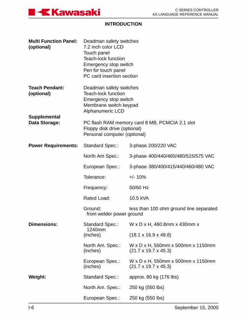
Multi Function Panel: Deadman safety switches(optional) 7.2 inch color LCD
Touch panelTeach-lock functionEmergency stop switchPen for touch panelPC card insertion section
Teach Pendant: Deadman safety switches(optional) Teach-lock function
Emergency stop switchMembrane switch keypadAlphanumeric LCD
SupplementalData Storage: PC flash RAM memory card 8 MB, PCMCIA 2.1 slot
Floppy disk drive (optional)Personal computer (optional)
Power Requirements: Standard Spec.: 3-phase 200/220 VAC
North Am Spec.: 3-phase 400/440/460/480/515/575 VAC
European Spec.: 3-phase 380/400/415/440/460/480 VAC
Tolerance: +/- 10%
Frequency: 50/60 Hz
Rated Load: 10.5 kVA
Ground: less than 100 ohm ground line separatedfrom welder power ground
Dimensions: Standard Spec.: W x D x H, 460.8mm x 430mm x1240mm
(inches) (18.1 x 16.9 x 48.8)
North Am. Spec.: W x D x H, 550mm x 500mm x 1150mm(inches) (21.7 x 19.7 x 45.3)
European Spec.: W x D x H, 550mm x 500mm x 1150mm(inches) (21.7 x 19.7 x 45.3)
Weight: Standard Spec.: approx. 80 kg (176 lbs)
North Am. Spec.: 250 kg (550 lbs)
European Spec.: 250 kg (550 lbs)
SYSTEM OVERVIEW
1-1November 14, 2000
C SERIES CONTROLLERAS LANGUAGE REFERENCE MANUALKa a aw s k
1.0 SYSTEM OVERVIEW ........................................................................................ 1-21.1 AS System Status .............................................................................................. 1-21.2 Notations and Conventions ................................................................................ 1-61.3 Displaying with the Terminal ............................................................................... 1-71.4 Location Information........................................................................................... 1-81.4.1 Precision Location .............................................................................................. 1-81.4.2 Transformation Location ..................................................................................... 1-81.4.3 Compound Transformation Location (Relative Transformation) ........................ 1-101.5 Numeric Information ......................................................................................... 1-121.5.1 Integers ............................................................................................................ 1-121.5.2 Real Numbers .................................................................................................. 1-121.5.3 Logical Values .................................................................................................. 1-121.5.4 ASCII Values .................................................................................................... 1-131.6 Variable Names ................................................................................................ 1-131.6.1 Location Variables ............................................................................................ 1-141.6.2 Real Variables .................................................................................................. 1-141.6.3 Character String Variables ............................................................................... 1-151.7 Numerical Expression ...................................................................................... 1-171.7.1 Operators ......................................................................................................... 1-171.8 Monitor Commands .......................................................................................... 1-201.8.1 Program Instructions ........................................................................................ 1-21
SYSTEM OVERVIEW
C SERIES CONTROLLERAS LANGUAGE REFERENCE MANUAL
1-2 November 14, 2000
Ka a aw s k
1.0 SYSTEM OVERVIEW
AS Language for the C controller is a software based control system and high-levellanguage used to interface with the robot controller and control robot motion. The ASsoftware is permanently stored in the robot controller’s memory and is activated as soonas controller power is turned on. It continuously generates robot control commands andcan simultaneously interact with a programmer, permitting on-line program generationand modification. The multi function panel and/or a personal computer is used to ac-cess AS Language.
1.1 AS SYSTEM STATUS
The AS system consists of the monitor mode, the editor mode, and the playback mode.
• Monitor Mode: This is the basic mode in the AS system. Monitor commands areexecuted in this mode. The editor or playback modes are accessed from this mode.
• Editor Mode: This mode enables the user to create a new program or modify anexisting program. Only editor commands are accepted by the system in this mode.
• Playback Mode: The system is in the playback mode during program execution.Computations for robot motion control are performed and commands entered fromthe terminal are processed during unoccupied CPU time. Some monitor commandscannot be executed in playback mode. Refer to unit 4, Monitor and Editor Com-mands for details.
The AS system is controlled by the following system switches:
• CHECK.HOLD
This switch is used with the AS Language commands EXECUTE, DO, STEP,MSTEP and CONTINUE. When the CHECK.HOLD switch is ON these commandsare available only if the HOLD/RUN switch is in the HOLD position. The controlleraccepts these commands with the HOLD/RUN switch in the HOLD position butrobot motion is not initiated until the switch is manually placed in the RUN position.Default setting is OFF.

SYSTEM OVERVIEW
1-3November 14, 2000
C SERIES CONTROLLERAS LANGUAGE REFERENCE MANUALKa a aw s k
Figure 1-1 CP Switch
Robot Path Switch Setting
ON
OFF
Accuracy Range
• CYCLE.STOP
This switch is used in conjunction with an external input signal to stop the motion ofthe robot. With the switch ON, when the input signal is received the robot stops andthe cycle start light turns OFF. When the program is started again it starts at thebeginning. If the program is called from another program, the program restarts atthe beginning of the main program. With the switch OFF, when the input signal isreceived the robot stops and the cycle start light remains ON. The robot is in a holdcondition and when the program is started again, it continues at the point in thecycle where it was stopped.Default setting is OFF.
• OX.PREOUT
This switch affects the timing of output signal generation in block step programs.When the switch is ON, an output programmed for a given point is turned ON whenthe robot begins motion to the point. With the OX.PREOUT switch OFF, an outputprogrammed for a given point is not turned ON until the robot reaches the accuracyrange of the point. Figure 1-2 shows the effects the OX.PREOUT switch on signaltiming.Default setting is ON.
• CP
The CP switch is used to enable or disable the continuous path function. When theswitch is ON, the robot makes smooth transitions between motion segments withinthe accuracy ranges set. When the switch is OFF, the robot decelerates and stopsat the end of each motion segment regardless of accuracy.Default setting is ON

SYSTEM OVERVIEW
C SERIES CONTROLLERAS LANGUAGE REFERENCE MANUAL
1-4 November 14, 2000
Ka a aw s k
• PREFETCH.SIGINS
This switch is used in conjunction with AS Language instructions and has the sameeffect on signal timing as the OX.PREOUT switch has with blockstep instructions.Default setting ON. The AS Language instructions affected are; SWAIT, TWAIT,SIGNAL, PULSE, DLYSIG, RUNMASK, RESET and BITS.
• QTOOL
This switch allows the user to identify tools to use in block step or AS Languageprogramming. When the QTOOL switch is ON, nine tools are available for program-ming and jogging. The tool dimensions are recorded and assigned a tool numberusing auxiliary function 48. When the QTOOL switch is ON, the selected tool di-mensions are in effect for jogging and linear playback of block step programs.When the QTOOL switch is OFF, the tool identified with AS Language instructionsis used.Default setting is ON.
• REP_ONCE (Repeat Once)
When this switch is ON, programs run one time. With the switch OFF, the programruns continuously.Default setting is OFF.
Figure 1-2 OX.PREOUT Switch
SYSTEM OVERVIEW
1-5November 14, 2000
C SERIES CONTROLLERAS LANGUAGE REFERENCE MANUALKa a aw s k
• STP_ONCE (Step Once)
When this switch is ON, the repeat condition function of progressing through aprogram one step at a time is active. The step forward key is used to step through aprogram. When the switch is OFF, programs run continuously.Default setting is OFF.
• AFTER.WAIT.TIMER
When this switch is ON, timers begin timing for a specified step when all wait condi-tions are satisfied. With the switch OFF, timers begin timing when the robot reachescoincidence of the taught point.Default setting is OFF.
• AUTOSTART.PC
The AUTOSTART.PC, AUTOSTART2.PC, and AUTOSTART3.PC switches automati-cally start the associated PC program when controller power is turned on.Default setting is OFF.
• ERRSTART.PC
When this switch is ON and specified errors (assigned dedicated signals) occur, aPC program is run as soon as the error is detected.Default setting is OFF.
• MESSAGES
Enables or disables message output (PRINT or TYPE) to the keyboard screen.Default setting is ON
• RPS (Random Program Selection)
This switch enables or disables the random selection of programs based on binarystatus of dedicated inputs.Default setting is OFF
• SCREEN
This switch enables or disables scrolling of the screen when information is too largeto fit on one screen.Default setting is ON
SYSTEM OVERVIEW
C SERIES CONTROLLERAS LANGUAGE REFERENCE MANUAL
1-6 November 14, 2000
Ka a aw s k
• DISPIO_01
This switch allows the user to select the type of display for viewing the status ofinputs and outputs. If the switch is ON, 1s and 0s are displayed to identify thesignal state of individual signals. A 1 represents an ON signal, while a 0 representsan OFF signal. If the switch is off, an ON signal is represented by an O, while an Xrepresents a OFF signal. Dedicated signals are represented by uppercase Xs andOs.Default setting is OFF.
1.2 NOTATIONS AND CONVENTIONS
A mixture of uppercase and lowercase words is used throughout this manual, all keywords are shown in uppercase and all elements freely specified by the user are shownin lowercase.
Abbreviated notations are used as well. For example, the EXECUTE command can beabbreviated as EX.
At least one space (blank) or tab is necessary as a delimiter between the instruction (orcommand) name and its arguments. The excess spaces or tabs are ignored by thesystem.
Monitor commands and program instructions are processed by pressing the ENTERkey.
Many instructions or commands have arguments which can be omitted. If there is acomma following the optional argument, the comma should be retained even if theargument is omitted. If all successive arguments are omitted, commas may also beomitted.
In this manual, values are expressed in decimal notations, unless noted otherwise.Some instructions and commands require several types of arguments. Mathematicalexpressions can be used to designate the value as arguments. The acceptable valuemay be restricted. The following rules show how the values are interpreted in variouscases.
• The AS Language follows the conventions established by the American StandardCode for Information Interchange (ASCII). An ASCII character is specified by prefix-ing a character with an apostrophe (‘). For example, ddd = ‘A assigns 65 to ddd.
• All numerical expressions evaluated by the system result in a real value.

SYSTEM OVERVIEW
1-7November 14, 2000
C SERIES CONTROLLERAS LANGUAGE REFERENCE MANUALKa a aw s k
• DISTANCE is used to define the position to which the robot moves. The unit fordistance is millimeters, although units are not required to be entered with values.Values entered for distances can be positive or negative, with their magnitudeslimited by a number representing the maximum reach of the robot. For example,
> DO DRAW 50,100,-50 moves the robot 50 mm in X, 100 mm in Y, and 50 mm inthe Z Cartesian direction.
• ANGLES in degrees are entered to define and modify orientations the robot as-sumes at named locations, and to describe angular positions of robot joints. Thevalues can be positive or negative, with their magnitudes limited by 180 degrees or360 degrees depending on the context. For example,
> DO DRIVE 2,45,75 moves joint 2 of the robot 45° at 75% of the repeat speed.
• JOINT NUMBER is an integer value from one to the number of joints available onthe robot, including a servo-controlled external axes.
• SIGNAL NUMBER is used to identify binary (on/off) signals. The value is an integerin the range of 1-256 (output signals), 1001-1256 (input signals) depending on thenumber of I/O signals available in the controller. Negative signal numbers indicatean OFF state.
• Whenever an existing program is saved, or renamed, the new name is entered first,followed by the old name. The above also holds true for the POINT command. Forexample:
Command New Name = Old NameSAVE Right_Side = Fender3RENAME test = test.tmp
1.3 DISPLAYING WITH THE TERMINAL
The operator can display various types of information in the monitor mode or playbackmode. Directories and listings of programs, locations, variable data, and weld conditionsare displayed by entering specific monitor commands. For additional information, referto section 4.2, Program and Data Control Commands.
SYSTEM OVERVIEW
C SERIES CONTROLLERAS LANGUAGE REFERENCE MANUAL
1-8 November 14, 2000
Ka a aw s k
1.4 LOCATION INFORMATION
Locations recorded in the controller’s memory are comprised of values which designatedestinations for robot motion. The values recorded in memory are either Cartesiancoordinates or robot joint angles. A Cartesian coordinate represents a point in the robotworkspace with a tool center point orientation at that point. A location recorded withjoint angles specifies a robot arm configuration at that point. When the robot is directedto move to a Cartesian location, two actions occur simultaneously: the robot is movedso the tool center point moves to the specified point, and the tool is rotated to the pre-scribed orientation. When the robot is directed to move to a location recorded with jointangles, the processor calculates a motion path based on the encoder values of therecorded point, then moves the arm until all encoder values match those of the recordedpoint. There are two types of location information, transformation locations (Cartesiancoordinates) and precision locations (joint angles).
1.4.1 PRECISION LOCATION
A precision location’s value is represented by the exact position of the individual robotjoints in degrees. There are several characteristics of precision locations that should beconsidered. These characteristics result from joint angles being recorded.
Advantages of precision locations: Playback precision is achieved and there is noambiguity about robot configuration at a location.
Disadvantages of precision locations: The values recorded can be used by any modelof robot, however the tool center point location is different when used by a robot ofdifferent physical size. Precision locations cannot be easily modified to compensate forlocation changes in the robot workspace, because a change requires complete knowl-edge of the relationship between the positions of all robot joints and the locations in therobot workspace.
1.4.2 TRANSFORMATION LOCATION
A transformation location is represented by defining the location in terms of a Cartesian(XYZ) reference frame fixed to the base of the robot. The position of the tool centerpoint is defined with X, Y, and Z coordinates, and the tool orientation is defined by threeangles measured from the coordinate axes.

SYSTEM OVERVIEW
1-9November 14, 2000
C SERIES CONTROLLERAS LANGUAGE REFERENCE MANUALKa a aw s k
Advantages of transformation locations: A value defined for use with one robot can beused with a different robot having a similar work envelope because the value is definedin terms of workspace coordinates. Transformations are easily modified to change alocation within the robot workspace. A powerful feature of transformation locations isthe ability to define locations as combinations of values. This is called compound orrelative transformation. Such values are used to define the location of a part relative toits fixturing.
Disadvantages of transformation locations: Since a transformation location defines thelocation of the tool center point in terms of coordinates in the workspace, no informationis provided about the specific robot configuration at the location. Whenever a transfor-mation is used to define the destination of a robot motion, the AS system must convertthe transformation location into an equivalent precision location so it knows how to movethe individual joints. This conversion can introduce small location errors. Despite thesedisadvantages, transformation locations are generally much more convenient thanprecision locations.
SYSTEM OVERVIEW
C SERIES CONTROLLERAS LANGUAGE REFERENCE MANUAL
1-10 November 14, 2000
Ka a aw s k
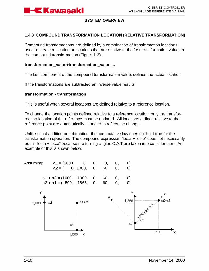
Assuming: a1 = (1000, 0, 0, 0, 0, 0)a2 = ( 0, 1000, 0, 60, 0, 0)
a1 + a2 = (1000, 1000, 0, 60, 0, 0)a2 + a1 = ( 500, 1866, 0, 60, 0, 0)
1.4.3 COMPOUND TRANSFORMATION LOCATION (RELATIVE TRANSFORMATION)
Compound transformations are defined by a combination of transformation locations,used to create a location or locations that are relative to the first transformation value, inthe compound transformation (Figure 1-3).
transformation_value+transformation_value....
The last component of the compound transformation value, defines the actual location.
If the transformations are subtracted an inverse value results.
transformation - transformation
This is useful when several locations are defined relative to a reference location.
To change the location points defined relative to a reference location, only the transfor-mation location of the reference must be updated. All locations defined relative to thereference point are automatically changed to reflect the change.
Unlike usual addition or subtraction, the commutative law does not hold true for thetransformation operation. The compound expression “loc.a + loc.b” does not necessarilyequal “loc.b + loc.a” because the turning angles O,A,T are taken into consideration. Anexample of this is shown below.
SYSTEM OVERVIEW
1-11November 14, 2000
C SERIES CONTROLLERAS LANGUAGE REFERENCE MANUALKa a aw s k
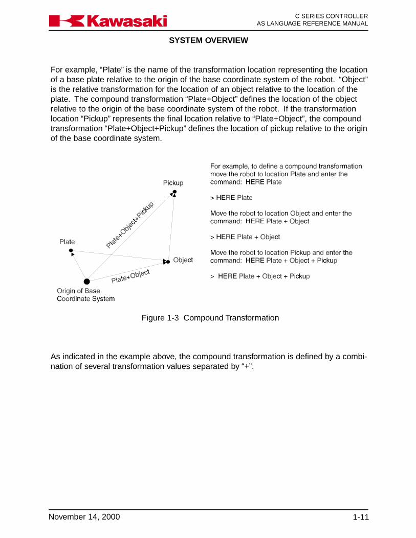
Figure 1-3 Compound Transformation
As indicated in the example above, the compound transformation is defined by a combi-nation of several transformation values separated by “+”.
For example, “Plate” is the name of the transformation location representing the locationof a base plate relative to the origin of the base coordinate system of the robot. “Object”is the relative transformation for the location of an object relative to the location of theplate. The compound transformation “Plate+Object” defines the location of the objectrelative to the origin of the base coordinate system of the robot. If the transformationlocation “Pickup” represents the final location relative to “Plate+Object”, the compoundtransformation “Plate+Object+Pickup” defines the location of pickup relative to the originof the base coordinate system.
SYSTEM OVERVIEW
C SERIES CONTROLLERAS LANGUAGE REFERENCE MANUAL
1-12 November 14, 2000
Ka a aw s k
1.5 NUMERIC INFORMATION
Numeric information is a combination of numerals, variables, operators, and functionswhich return numeric values. Numeric expressions are used not only for mathematicalcalculations, but also as arguments for monitor commands or program instructions.Numeric values used in the AS system are divided into the four types described below:
1.5.1 INTEGERS
Integers are values without fractional parts (whole numbers). Values with full precisionranges are from -16,777,216 to +16,777,216. Values that exceed this range arerounded to seven significant digits. Integer values are usually entered as decimal num-bers, however, it may be more convenient to enter them in binary or hexadecimal nota-tions.
1.5.2 REAL NUMBERS
Real numbers have both the integer part and a fractional part which can range from-3.4E +38 ~ 3.4E +38. Like integers, real values are positive, zero or negative. Theycan be represented in scientific notation. Real values are stored with an accuracy ofapproximately seven digits, but actual values may have less precision caused by acalculation error.
1.5.3 LOGICAL VALUES
Logical values have only two states, ON or OFF. These two states are also referred toas TRUE and FALSE respectively. A value of negative one (-1) is assigned for the TRUEor ON state and a value of zero (0) is assigned for the FALSE or OFF state.
> AA = ON Stores a value of -1 in variable AA> BB = FALSE Stores a value of 0 in variable BB> CC = -TRUE Stores a value of 1 in variable CC
ON, OFF, TRUE, and FALSE are AS Language key-words.
NOTE
SYSTEM OVERVIEW
1-13November 14, 2000
C SERIES CONTROLLERAS LANGUAGE REFERENCE MANUALKa a aw s k
1.5.4 ASCII VALUES
An ASCII value is the numeric value of one ASCII character. An ASCII value is specifiedby prefixing the character with an apostrophe (‘).
> X = ‘A Stores a value of 65 in variable X> X = ‘a Stores a value of 97 in variable X
1.6 VARIABLE NAMES
Variable names must start with an alphabetic character and can contain only letters,numbers, periods, and underlines. The letters used in variable names can be enteredeither in lowercase or uppercase. The length of a name is limited to fifteen characters.AS Language commands should not be used and in some cases cannot be used asvariable names because they cause ambiguity with the AS system keywords, but theirabbreviations can be used. For example, the following names cannot be used:
3P (first character is not alphabetic)part#2 (“#” prefix for precision location name)random (AS keyword)
Precision location names must be preceded by the symbol “#” to differentiate them fromtransformation location names. String variables must be preceded by the symbol “$” todifferentiate them from real and transformation variables.
pick (transformation or real variable value)#pick (precision value)$count (string variable)
A transformation location and precision location may have the same name, however, thesame name may not be used for transformation values and real values. A definedvariable may be used by any program in the system.
Array variables can be used for any type of information. Arrays consist of several valuesunder the same name and these values are distinguished from each other by their indexvalue. In order to designate array elements, attach an element number (index) enclosedby brackets to the array name. For example, “part[7]” indicates the seventh element ofthe array “part”. Indexes should be integers within the range 0 to 9999.
Location, real, string, and array are four types of variables within the AS system. Thesefour variable types are explained on the following pages.

SYSTEM OVERVIEW
C SERIES CONTROLLERAS LANGUAGE REFERENCE MANUAL
1-14 November 14, 2000
Ka a aw s k
1.6.1 LOCATION VARIABLES
A location variable (precision or transformation) is automatically defined when a value isassigned for the first time. Prior to this, the location name is undefined. If a programuses an undefined variable, an error occurs. The user defines location variables byusing monitor commands or program instructions. The following are examples of loca-tion variable values:
Precision location value: name with joint angles
JT1 JT2 JT3 JT4 JT5 JT6#weld 90.000° 145.056° -95.098° 90.000 °45.000° 0.000°
Transformation location value: name with joint angles and turning angles
X Y Z O A Tweld 60.000 mm 145.050 mm -95.098 mm 90.000° 45.000° 0.000°
1.6.2 REAL VARIABLES
Real variables are defined using the assignment instruction (=). The format for assign-ing a real variable is:
Variable_name = numeric_valuea = 6b = 7c = a + b
The variable on the left side may be either a scalar variable (i.e.,“count”) or an arrayelement (i.e., “x [2]”). A variable is defined automatically the first time it is assigned avalue. If a program uses an undefined variable, an error occurs. The numeric value onthe right side may be a constant, a variable, or a numeric expression. When an assign-ment instruction is processed, the value on the right side of the assignment instruction isfirst computed, then the value is assigned to the variable on the left side.
For example, the assigned value “x=3” assigns the value 3 to the variable “x”. If a vari-able on the left side has never been used it is defined automatically, and if it has alreadybeen assigned a value, its current value is replaced by a new assigned value. Theabove example is read as “assign 3 to x” and not “x is equal to 3”. The following ex-ample shows this difference: x = x + 1.

SYSTEM OVERVIEW
1-15November 14, 2000
C SERIES CONTROLLERAS LANGUAGE REFERENCE MANUALKa a aw s k
If the example is a general equation, it is read as “x is equal to x plus 1”, which does notmake sense mathematically. It must be read as “assign the value of x plus 1 to x”. Inthis case, the sum of the current value of “x” and 1 is calculated. In the next step, thatvalue is assigned to “x” as a new value. Therefore, the result of the above assignmentinstruction is to increase the value of x by 1. In this example, the variable “x” shouldhave been previously defined.
x = 3x = x + 1
In the case above, the resulting value of “x” is 4.
1.6.3 CHARACTER STRING VARIABLES
The character information referred to in the AS system is indicated as a string of ASCIIcharacters enclosed by quotation marks (“). Since the quotation marks indicate thebeginning and end of a character string, they cannot be included in the string. ASCIIcontrol characters (CTRL, CR, LF, etc.) also cannot be included in the string. For ex-ample, a command for printing (displaying on the screen) would be entered as:
PRINT “Kawasaki”
Character strings are defined by using the assignment instruction (=). The format forassigning a character variable is :
$string_variable = string_value(name of variable) (string expression)
The string variable on the left side may be either a scalar variable (ie., “$name”) or anarray element (ie., “$line [2]”). A variable is defined automatically the first time it isassigned a value. If a program uses an undefined variable, an error occurs. The char-acter string on the right side may be a constant, a string variable, or a string expression.When an assignment instruction is processed, the value on the right side is first com-puted, then the value is assigned to the variable on the left side. If the variable on theleft side has never been used, it is defined automatically, and if it has already beenused, its current value is replaced by a new assigned value.
SYSTEM OVERVIEW
C SERIES CONTROLLERAS LANGUAGE REFERENCE MANUAL
1-16 November 14, 2000
Ka a aw s k
The following is an example of string variable assignment:
$First = “Kawasaki”$Last = “ Robotics”$Name = $First + $Last + “ Inc.”
In the above example, the string variable $Name is assigned the sum of $First, $Last,and the character string “Inc.”. The command PRINT or TYPE $Name returns the stringvalue: Kawasaki Robotics Inc.
1.6.4 Arrays
An array is a group of values that share a single name. Location variables can be sca-lars or arrays. A location scalar is a single location value. Each value in an array iscalled an element of the array. An element of a location array is specified in exactly thesame way as an element of a numeric array by appending an index enclosed in bracketsto the array name. For example, “part[7]” refers to element 7 of the array “part.” Indexesmust be integers in the range of 0 ~ 9999. Three examples of arrays are describedbelow:
Example 1:
PROGRAM OUTPUT
HERE edge edge[1]=120.456DECOMPOSE edge[1]=edge edge[2]=145.670FOR i=1 to 6 edge[3]=-95.432TYPE “edge[“I1,i,”]=“,/D,edge[i] edge[4]=90.456END edge[5]=45.000edge[6]=10.018
In the above example, the current location of the robot is defined as “edge”. The DE-COMPOSE instruction extracts component values of edge (XYZOAT) consecutively (1through 6). The program instructions between the FOR and END statements are ex-ecuted repeatedly and the TYPE instruction displays the component values of edgeindividually.

SYSTEM OVERVIEW
1-17November 14, 2000
C SERIES CONTROLLERAS LANGUAGE REFERENCE MANUALKa a aw s k
Example 2:
FOR i = 2 to 6 STEP 2DRAW 100, 10 * i + 7, 50HERE weld[i]END
In the above example, the robot moves 100 mm in the X direction, a calculated amount(10 * i + 7) mm in the Y direction, and 50 mm in the Z direction, and define the locationas weld[i].
The FOR statement, in this example increments the value of “i” in increments of two, forexample:
i = 2, i = 4, i = 6.
Example 3:
PROGRAM SUBPROGRAM OUTPUT
Main() Pg10() Corner 1$POINT[1]=”Corner1” FOR i=1to3 edge$POINT[2]=”edge” JMOVE weld[i] Corner2$POINT[3]=”Corner2” TYPE$POINT[i]CALL pg10 END
In the above example, the array is used as a string array. Each move of the robot dis-plays the strings assigned in the main program.
1.7 NUMERICAL EXPRESSION
The numerical expression is a combination of numeric values and variables combinedtogether with operators. The expressions are completed by the addition of functionalmodifiers to the numeric values and variables. All numerical expressions evaluated bythe system result in a real value. The interpretation of the value depends on the contextin which the expression appears. For example, an expression specified for an arrayindex is interpreted as yielding an integer value.
1.7.1 OPERATORS
For describing expressions, arithmetic, logical, and binary, operators are provided. All ofthese operators combine two values to obtain a single resulting value, except three: thetwo operators (NOT and COM) operate on a single value and the operator (-) operateson one or two values. The operators are described on the following page.

SYSTEM OVERVIEW
C SERIES CONTROLLERAS LANGUAGE REFERENCE MANUAL
1-18 November 14, 2000
Ka a aw s k
Arithmetic Operators: + addition- subtraction or negation* multiplication/ division^ power (if ab, a<0 results in error)
x=(-2)^2 results in an errorx= -2^2 assigns -4 to x
MOD remainderx=5 MOD 2 assigns the remainder of 5/2 (1in this case) to x
Relational Operator: < less than<=, (=<) less than or equal to== equal to<> not equal to>=, (=>) greater than or equal to> greater than
Logical Operator: AND logical ANDNOT logical complementOR logical ORXOR exclusive logical OR
The logical operators are used in Boolean operations such as logical OR (0+1=1,1+1=1, 0+0=0), logical AND (0x1=0, 1x1=1, 0x0=0), and logical XOR (0+1=1, 1+1=0,0+0=0). The logical operators are not used for calculating numeric values, but for deter-mining the logical state (TRUE or FALSE) of the conditional expression. If a numericvalue is zero (0), it is considered to be FALSE (0). All nonzero values are considered tobe TRUE(-1).
OPERATION RESULT
0 AND 0 0 (FALSE)1 AND 1 -1 (TRUE)1 OR 0 -1 (TRUE)

SYSTEM OVERVIEW
1-19November 14, 2000
C SERIES CONTROLLERAS LANGUAGE REFERENCE MANUALKa a aw s k
Binary Operator: BAND Binary ANDBOR Binary ORBXOR Binary XORCOM Binary Complement
The binary logical operators perform logical operations for each respective bit of twonumeric values.
OPERATION RESULT
5 BOR 3 70101 BOR 0011 01115 BAND 9 10101 BAND 1001 0001
Expressions are evaluated according to a sequence of priorities. Parentheses can beused to group the components of an expression and to control the order in which theoperations are performed. When expressions containing parentheses are evaluated, theexpression within the innermost pair is evaluated first, then the system works toward theoutermost pair. Within parentheses, expressions are evaluated in the following order:
1. Evaluate functions and arrays.2. Process power operator “ ^ ”.3. Process unary operators “ - ” (single component).4. Process multiplication “ * ” and division “ / ” operators from left to right.5. Calculate remainders (MOD operators) from left to right.6. Process addition “ + ” and subtraction “ - ” operators from left to right.7. Process relational operators from left to right.8. Process COM operators from left to right.9. Process BAND operators from left to right.10. Process BOR operators from left to right.11. Process BXOR operators from left to right.12. Process NOT operators from left to right.13. Process AND operators from left to right.14. Process OR operators from left to right.15. Process XOR operators from left to right.
The logical expressions result in a logical value TRUE or FALSE. A logical expressioncan be used as a condition in which the execution of a program or program steps isperformed. When evaluating logical expressions, the value zero is considered FALSEand all nonzero values are considered TRUE. Therefore, all real values or real valueexpressions can be used as a logical value.

SYSTEM OVERVIEW
C SERIES CONTROLLERAS LANGUAGE REFERENCE MANUAL
1-20 November 14, 2000
Ka a aw s k
For example, the following two statements have the same meaning, but the secondstatement is easier to understand.
IF x GOTO 10 (If the value of x is true, goto label 10 in the program)
IF x <> 0 GOTO 10 (If the value of x is not equal to 0, goto label 10 in the program)
1.8 MONITOR COMMANDS
TEACH location variable name
The TEACH command is used in conjunction with the small teach pendant. With thesmall teach pendant connected, the TEACH command is entered at the monitor prompt.
The small teach pendant is used to jog the robot to the locations used in the specifiedprogram. When the RECORD key on the teach pendant is pressed, the location isplaced into the system memory with the specified location variable name followed by a0. Each time the RECORD key is pressed the number following the location variablename is increased by one.
For example, the command TEACH loc is entered at the monitor prompt, the first timethe RECORD key on the small teach pendant is pressed, a location with the name loc0is stored in the system memory. The next time the RECORD key of the small teachpendant is pressed, the location stored in system memory is loc1.
The TEACH command allows the programmer to record transformation locations withouthaving to exit the work cell for each new location.
The HERE command stores the current robot location in the specified precision ortransformation variable.
HERE #pallet
The POINT command defines the named location variable using an existing locationvariable. Component values may also be entered from the keyboard.
POINT a = b
Assigns component values of location variable b into location variable a.
POINT #a
Displays the current component of location variable #a. If the location variable is notdefined, zeros are displayed.

SYSTEM OVERVIEW
1-21November 14, 2000
C SERIES CONTROLLERAS LANGUAGE REFERENCE MANUALKa a aw s k
1.8.1 PROGRAM INSTRUCTIONS
The commands HERE and POINT may also be used in a program as program instruc-tions. For example,
JMOVE loc1POINT loc2=loc1DRAW 347.28, ,479.0HERE loc3
In the above example, the robot moves to loc1. The POINT command then assignscomponent values of loc1 to loc2. The DRAW command moves the robot 347.28 mm inX, and 479 mm in the Z direction. Finally, loc3 is defined by the HERE command.
SAFETY
2-1November 14, 2000
Ka a aw s k C SERIES CONTROLLERAS LANGUAGE REFERENCE MANUAL
2.0 SAFETY ........................................................................................................... 2-22.1 Introduction....................................................................................................... 2-22.2 Safety Conventions and Symbology ................................................................. 2-32.2.1 Warning/Caution Symbols ................................................................................ 2-32.3 Safety Categories ............................................................................................. 2-42.3.1 Personal Safety ................................................................................................ 2-42.3.2 Safety During Operation ................................................................................... 2-62.3.3 Safety During Programming ............................................................................. 2-72.3.4 Safety During Inspection and Maintenance ...................................................... 2-82.4 Safety Features ................................................................................................ 2-92.5 Work Envelope Drawings ............................................................................... 2-102.5.1 FS02N/FS03N ................................................................................................ 2-102.5.2 FS06L ............................................................................................................. 2-112.5.3 FC06N/FS06N/FW06N/FS10C....................................................................... 2-122.5.4 FS10N ............................................................................................................ 2-132.5.5 FS10E ............................................................................................................ 2-142.5.6 FS10L ............................................................................................................. 2-152.5.7 FS20C ............................................................................................................ 2-162.5.8 FS20N ............................................................................................................ 2-172.5.9 FS30L ............................................................................................................. 2-182.5.10 FS30N/FS45C ................................................................................................ 2-192.5.11 FS45N ............................................................................................................ 2-202.5.12 UB150 ............................................................................................................ 2-212.5.13 UT100/150/200............................................................................................... 2-222.5.14 UX70 .............................................................................................................. 2-232.5.15 UX100/120/150 .............................................................................................. 2-242.5.16 UX200 ............................................................................................................ 2-252.5.17 UX300 ............................................................................................................ 2-262.5.18 UZ100/120/150............................................................................................... 2-272.5.19 ZD130............................................................................................................. 2-282.5.20 ZX130L ........................................................................................................... 2-292.5.21 ZX130U .......................................................................................................... 2-302.5.22 ZX165U .......................................................................................................... 2-312.5.23 ZX200S .......................................................................................................... 2-322.5.24 ZX200U .......................................................................................................... 2-332.5.25 ZX300S .......................................................................................................... 2-34

SAFETY
C SERIES CONTROLLERAS LANGUAGE REFERENCE MANUAL
2-2 November 14, 2000
Ka a aw s k
2.0 SAFETY
2.1 INTRODUCTION
Safety is an important consideration in the use of automated and robotic equipment inthe industrial environment. All operators, maintenance personnel, and programmersmust be aware of all automated equipment, peripheral and robotic equipment thatoccupies the work cell, and their associated operational and maintenance procedures.For this reason it is recommended that all personnel who operate, maintain, andprogram Kawasaki robots, attend a Kawasaki approved training course that would bepertinent to each employee’s specific job responsibilities.
The following safety sections in this text are designed to support and augment existingsafety guidelines that may be in use in your plant, and/or are provided by municipal,state, or federal governments, but are NOT designed to supplant or supersede anyexisting rules, regulations, or guidelines that may be in use. Because safety is theprimary responsibility of the user, owner, and/or employer, Kawasaki recommends thatspecific safety guidelines and recommendations be adopted from groups or individualsthat are professionals in safety design and implementation.
Two recommended sources for national and federal safety laws and regulations are:
1. OCCUPATIONAL SAFETY AND HEALTH STANDARDS, available from:U.S. Department of LaborOccupational Safety & Health AdministrationOffice of Public Affairs - Room N3647200 Constitution AvenueWashington, DC 20210
http://www.osha-slc.gov/SLTC/robotics/index.html
2. AMERICAN NATIONAL STANDARD FOR INDUSTRIAL ROBOTS AND ROBOTSYSTEMS-SAFETY REQUIREMENTS (ANSI/RIA R15.06-1992), available from:American National Standards Institute11 West 42nd StreetNew York, NY 10036
http://www.ansi.org/
All safety related issues and descriptions, either presented in written or oral form fromany representative of Kawasaki Robotics (USA), Inc., are intended to provide generalsafety precautions and procedures and, therefore, are not intended to provide all safetymeasures necessary for the protection of all personnel in the work environment.
SAFETY
2-3November 14, 2000
Ka a aw s k C SERIES CONTROLLERAS LANGUAGE REFERENCE MANUAL
! CAUTION
! WARNING
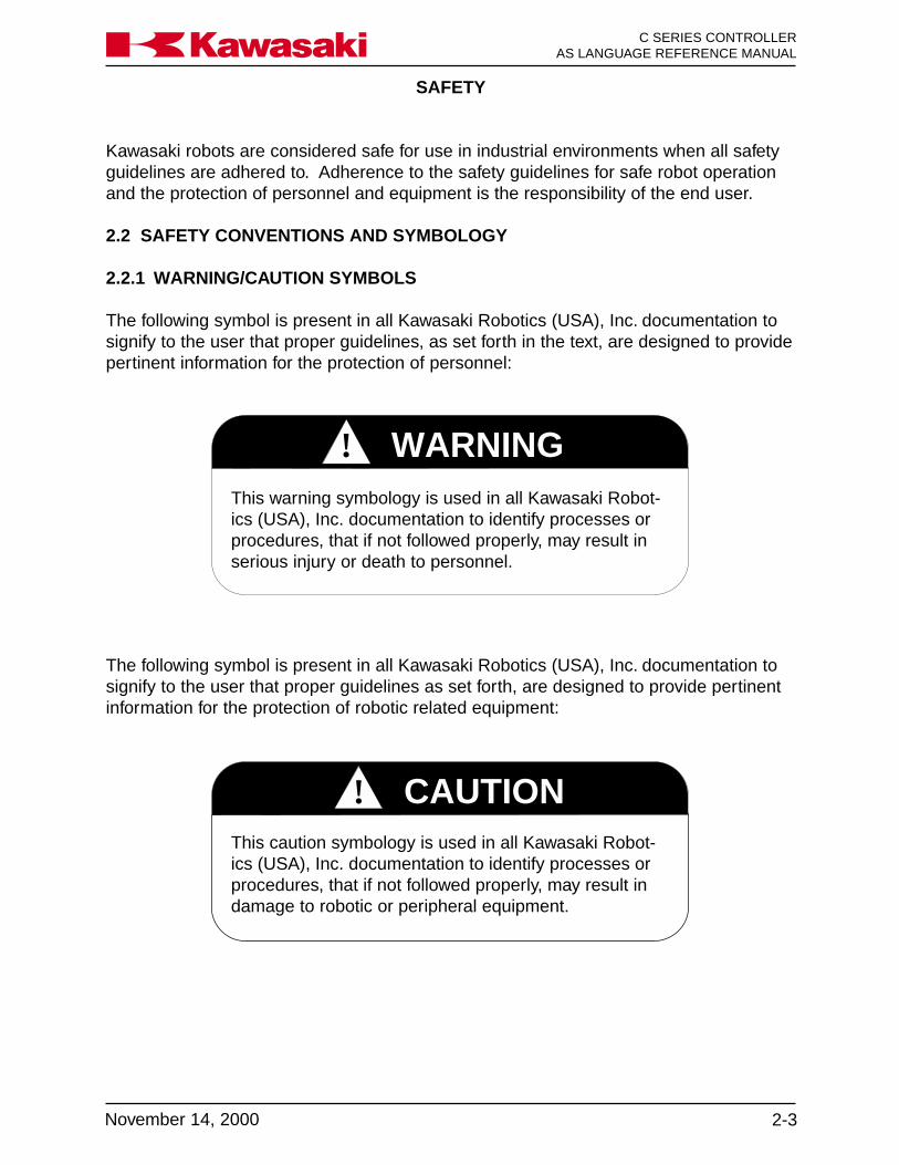
The following symbol is present in all Kawasaki Robotics (USA), Inc. documentation tosignify to the user that proper guidelines as set forth, are designed to provide pertinentinformation for the protection of robotic related equipment:
This warning symbology is used in all Kawasaki Robot-ics (USA), Inc. documentation to identify processes orprocedures, that if not followed properly, may result inserious injury or death to personnel.
This caution symbology is used in all Kawasaki Robot-ics (USA), Inc. documentation to identify processes orprocedures, that if not followed properly, may result indamage to robotic or peripheral equipment.
Kawasaki robots are considered safe for use in industrial environments when all safetyguidelines are adhered to. Adherence to the safety guidelines for safe robot operationand the protection of personnel and equipment is the responsibility of the end user.
2.2 SAFETY CONVENTIONS AND SYMBOLOGY
2.2.1 WARNING/CAUTION SYMBOLS
The following symbol is present in all Kawasaki Robotics (USA), Inc. documentation tosignify to the user that proper guidelines, as set forth in the text, are designed to providepertinent information for the protection of personnel:

SAFETY
C SERIES CONTROLLERAS LANGUAGE REFERENCE MANUAL
2-4 November 14, 2000
Ka a aw s k
2.3 SAFETY CATEGORIES
Personnel safety can be described in one of four categories:
• Personal safety
• Safety during operation
• Safety during programming
• Safety during inspection and maintenance
A description of each follows in this section.
2.3.1 PERSONAL SAFETY
Safety procedures must be an integral part of operational procedures for the operator,programmer, and maintenance person. These procedures must be followed explicitlyand on a regular basis. Safety procedures are followed on a daily basis, they shouldbecome a regular part of everyday operational procedures, which are designed toprotect the user. Some guidelines are presented in brief in the following section:
• Before operating or maintaining the robot or robot controller, be sure you fullyunderstand and comprehend ALL maintenance, operating, and programmingprocedures, and ensure that ALL safety related precautions are taken and compliedwith before these procedures are attempted.
• AVOID wearing loose clothing, scarves, wrist watches, rings, and jewelry whenworking on the controller and robot. It is also recommended that if ties must beworn in your shop environment that they be the clip-on variety rather than tied ties.
• ALWAYS wear safety glasses or goggles and approved safety shoes for your shopconditions. Follow all applicable OSHA, NIOSHA, MSHA, local, state, federal, andplant safety specifications and procedures.
• Know the ENTIRE work cell or area that the robot occupies.
• Be aware of the ENTIRE work envelope of the robot and any peripheral devices.
• Locate ALL emergency stop buttons or switches.
• AVOID trap points in which personnel could become trapped between a movingdevice and any stationary devices.

SAFETY
2-5November 14, 2000
Ka a aw s k C SERIES CONTROLLERAS LANGUAGE REFERENCE MANUAL
• Personnel should NEVER enter the work envelope during automatic operations.
• Ensure that ALL personnel are clear of the work envelope before initiating anymotion commands for the robot.
• Before initiating any motion commands, KNOW beforehand how the robot willperform when that command is given.
• Be sure that the ENTIRE work area is free of any debris, tools, fixturing, lubricants,and cleaning equipment before operation of the robot is attempted.
• If any personnel observe unsafe working conditions, report them IMMEDIATELY toyour supervisor or plant safety coordinator.
• ALL personnel should identify by name and function ALL switches, indicators, andcontrol signals that could initiate robot motion.
• NEVER defeat, render useless, jumper out, or bypass any safety related device,whether mechanical or electrical in design.
• ALL safety devices approved for use in your plant must be properly installed andmaintained to ensure personnel safety.
• NEVER attempt to stop or brake the robot during operation with your body or per-son.
• ONLY utilize E-stops to stop robot motion in emergency situations.
SAFETY
C SERIES CONTROLLERAS LANGUAGE REFERENCE MANUAL
2-6 November 14, 2000
Ka a aw s k
2.3.2 SAFETY DURING OPERATION
• During operation of the robot, identify the maximum reach of the robot in ALLdirections, which is referred to as the work envelope.
• ALWAYS keep your work area clean and free of any debris which includes, butis not limited to, oil, water, tool, fixturing, electronic test equipment, etc.
• During operations that involve the teach pendant, the ONLY person allowed inthe work envelope is the teacher, or the person operating the teach pendant.The teach pendant has provisions to protect the operator. These safetyprovisions include an E-stop, trigger switch, and deadman switch.
• NEVER block the operator’s path of retreat.
• During the teach operation of the robot ALWAYS have a path of retreat planned.
• AVOID pinch points.
SAFETY
2-7November 14, 2000
Ka a aw s k C SERIES CONTROLLERAS LANGUAGE REFERENCE MANUAL
2.3.3 SAFETY DURING PROGRAMMING
• During operation of the robot, be sure you are able to identify the maximumreach of the robot in ALL directions, which is referred to as the work envelope.
• During teach operations the ONLY person allowed in the work envelope is theteacher, or the person operating the teach pendant. The teach pendant hasprovisions to protect the operator including E-stop, trigger switch, and deadmanswitch.
• AVOID pinch points.
• During point-to-point playback operations, be aware that the robot is ONLYcognizant of its present location and the next point it is requested to move to.It will execute this move with total disregard to what may lie in its path whenthe move is executed.
• Playback accuracy and speed can affect the geometry of the path coordinates.Therefore, when changing accuracy or speed, ALWAYS test run the program ata slow speed or point-to-point mode before attempting the continuous pathoperation in the repeat mode.
• ALWAYS test run a new path program at a reduced speed or in point-to-pointmode prior to attempting a high-speed playback operation in the repeat mode.

SAFETY
C SERIES CONTROLLERAS LANGUAGE REFERENCE MANUAL
2-8 November 14, 2000
Ka a aw s k
! WARNING
• When removing an axis motor, be aware that the axis WILL fall if left unsupported.The brake assembly is in the servo drive motor, therefore, the axis of the robot willbe unsupported if removed.
• When using the axis brake release switches in the controller, be aware that the axisMAY fall if left unsupported.
• Before working on pneumatic or high pressure water supplies, turn off supplypressure and purge ALL lines to remove any residual pressure.
• Assign ONLY qualified personnel to perform all maintenance procedures.
• Consult ALL available documentation before attempting any repair or serviceprocedures.
• Use ONLY replacement parts approved by Kawasaki Robotics (USA), Inc.
• BEFORE attempting to adjust or repair a device in the robot controller that mayhave yellow interlock control circuit wires attached, locate the source of the powerand remove it by disconnecting the appropriate disconnect at its source.
• During inspection and maintenance procedures, if your installation is equippedwith safety fences and safety plugs, REMOVE and HOLD the safety plug whileperforming these operations. In addition, the safety procedures outlined aboveshould be adhered to.
The input side (top) of the controller disconnect may stillbe live when the controller disconnect is turned OFF. Ifwork is to be performed at the controller disconnectswitch, turn OFF the 3-phase power at the source, andtag and lockout the source disconnect.
2.3.4 SAFETY DURING INSPECTION AND MAINTENANCE
Before entering the work envelope to perform either inspection or maintenanceprocedures, turn off 3-phase power on the disconnect and tag and lockout thedisconnect switch.

SAFETY
2-9November 14, 2000
Ka a aw s k C SERIES CONTROLLERAS LANGUAGE REFERENCE MANUAL
2.4 SAFETY FEATURES
To safeguard the user, the Kawasaki robot system is equipped with many safetyfeatures. These safety items include:
• All E-stops are hard-wired.
• The multi function panel, small teach pendant, and operation panel are equippedwith red mushroom-type detented E-stop push buttons. If an optional interfacepanel is installed, the E-stop from the operation panel is relocated to the optionalinterface panel.
• All robot axes are monitored by the robot controller for velocity and deviation errors.
• Robot velocities are constantly monitored by software. Should an over-velocitycondition be detected, the robot will fault in a velocity error condition.
• Teach velocities and check mode velocities are limited to a maximum of 250mm/sec (9.843 in/sec).
• All robot axes have software limits.
• JT1 is equipped with overtravel limit switches (JT2 and JT3 are optional).
• All F-series, U-series, and Z-series mechanical units have overtravel hardstops onthe JT1, JT2, JT3, and JT5 axes.
• All robot axes are equipped with 24 VDC electromechanical brakes. Should therobot lose line power, the robot arm will not drop because the brakes are engagedwhen power is OFF at the robot controller.

SAFETY
C SERIES CONTROLLERAS LANGUAGE REFERENCE MANUAL
2-10 November 14, 2000
Ka a aw s k
2.5 WORK ENVELOPE DRAWINGS
2.5.1 FS02N/FS03N
Figure 2-1 FS02N/FS03N Work Envelope

SA
FE
TY
2-11N
ovember 14, 2000
Ka
aa
ws
kC
SE
RIE
S C
ON
TR
OLLE
RA
S LA
NG
UA
GE
RE
FE
RE
NC
E M
AN
UA
L
2.5.2 FS
06L
Figure 2-2 F
S06L W
ork Envelope

SA
FE
TY
C S
ER
IES
CO
NT
RO
LLER
AS
LAN
GU
AG
E R
EF
ER
EN
CE
MA
NU
AL
2-12N
ovember 14, 2000
Ka
aa
ws
k
2.5.3 FC
06N/F
S06N
/FW
06N/F
S10C
Figure 2-3 F
C06N
/FS
06N/F
W06N
/FS
10C W
ork Envelope

SA
FE
TY
2-13N
ovember 14, 2000
Ka
aa
ws
kC
SE
RIE
S C
ON
TR
OLLE
RA
S LA
NG
UA
GE
RE
FE
RE
NC
E M
AN
UA
L
Figure 2-4 F
S10N
Work E
nvelope
2.5.4 FS
10N

SA
FE
TY
C S
ER
IES
CO
NT
RO
LLER
AS
LAN
GU
AG
E R
EF
ER
EN
CE
MA
NU
AL
2-14N
ovember 14, 2000
Ka
aa
ws
kFigure 2-5 F
S10E
Work E
nvelope
2.5.5 FS
10E
SA
FE
TY
2-15N
ovember 14, 2000
Ka
aa
ws
kC
SE
RIE
S C
ON
TR
OLLE
RA
S LA
NG
UA
GE
RE
FE
RE
NC
E M
AN
UA
L
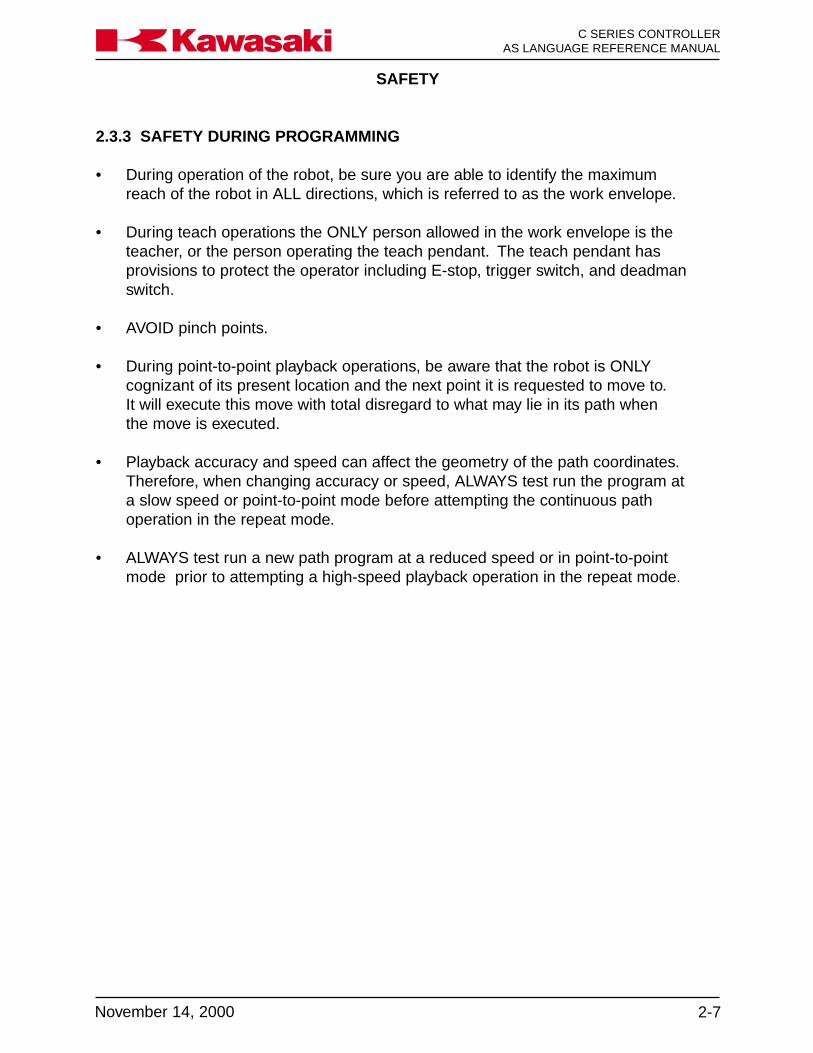
Figure 2-6 F
S10L W
ork Envelope
2.5.6 FS
10L
SA
FE
TY
C S
ER
IES
CO
NT
RO
LLER
AS
LAN
GU
AG
E R
EF
ER
EN
CE
MA
NU
AL
2-16N
ovember 14, 2000
Ka
aa
ws
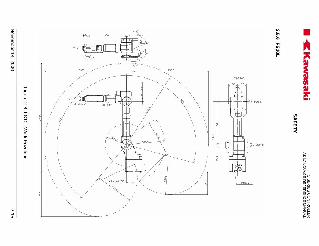
kFigure 2-7 F
S20C
Work E
nvelope
2.5.7 FS
20C

SA
FE
TY
2-17N
ovember 14, 2000
Ka
aa
ws
kC
SE
RIE
S C
ON
TR
OLLE
RA
S LA
NG
UA
GE
RE
FE
RE
NC
E M
AN
UA
L
Figure 2-8 F
S20N
Work E
nvelope
2.5.8 FS
20N
SA
FE
TY
C S
ER
IES
CO
NT
RO
LLER
AS
LAN
GU
AG
E R
EF
ER
EN
CE
MA
NU
AL
2-18N
ovember 14, 2000
Ka
aa
ws
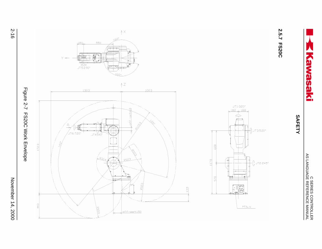
kFigure 2-9 F
S30L W
ork Envelope
2.5.9 FS
30L

SA
FE
TY
2-19N
ovember 14, 2000
Ka
aa
ws
kC
SE
RIE
S C
ON
TR
OLLE
RA
S LA
NG
UA
GE
RE
FE
RE
NC
E M
AN
UA
L
Figure 2-10 F
S30N
/FS
45C W
ork Envelope
2.5.10 FS
30N/F
S45C

SA
FE
TY
C S
ER
IES
CO
NT
RO
LLER
AS
LAN
GU
AG
E R
EF
ER
EN
CE
MA
NU
AL
2-20N
ovember 14, 2000
Ka
aa
ws
k
Figure 2-11 F
S45N
Work E
nvelope
2.5.11 FS
45N

SAFETY
2-21November 14, 2000
Ka a aw s k C SERIES CONTROLLERAS LANGUAGE REFERENCE MANUAL
2.5.12 UB150
Figure 2-12 UB150 Work Envelope
SAFETY
C SERIES CONTROLLERAS LANGUAGE REFERENCE MANUAL
2-22 November 14, 2000
Ka a aw s k
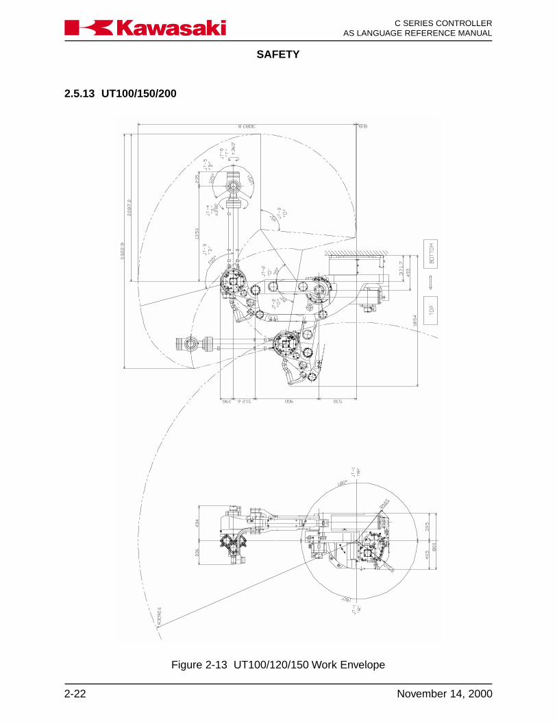
Figure 2-13 UT100/120/150 Work Envelope
2.5.13 UT100/150/200

SA
FE
TY
2-23N
ovember 14, 2000
Ka
aa
ws
kC
SE
RIE
S C
ON
TR
OLLE
RA
S LA
NG
UA
GE
RE
FE
RE
NC
E M
AN
UA
L
Figure 2-14 U
X70 W
ork Envelope
2.5.14 UX
70

SA
FE
TY
C S
ER
IES
CO
NT
RO
LLER
AS
LAN
GU
AG
E R
EF
ER
EN
CE
MA
NU
AL
2-24N
ovember 14, 2000
Ka
aa
ws
k
Figure 2-15 U
X100/120/150 W
ork Envelope
2.5.15 UX
100/120/150

SA
FE
TY
2-25N
ovember 14, 2000
Ka
aa
ws
kC
SE
RIE
S C
ON
TR
OLLE
RA
S LA
NG
UA
GE
RE
FE
RE
NC
E M
AN
UA
L
Figure 2-16 U
X200 W
ork Envelope
2.5.16 UX
200

SA
FE
TY
C S
ER
IES
CO
NT
RO
LLER
AS
LAN
GU
AG
E R
EF
ER
EN
CE
MA
NU
AL
2-26N
ovember 14, 2000
Ka
aa
ws
k
Figure 2-17 U
X300 W
ork Envelope
2.5.17 UX
300

SA
FE
TY
2-27N
ovember 14, 2000
Ka
aa
ws
kC
SE
RIE
S C
ON
TR
OLLE
RA
S LA
NG
UA
GE
RE
FE
RE
NC
E M
AN
UA
L
Figure 2-18 U
Z100/120/150 W
ork Envelope
2.5.18 UZ
100/120/150
SA
FE
TY
C S
ER
IES
CO
NT
RO
LLER
AS
LAN
GU
AG
E R
EF
ER
EN
CE
MA
NU
AL
2-28N
ovember 14, 2000
Ka
aa
ws
k
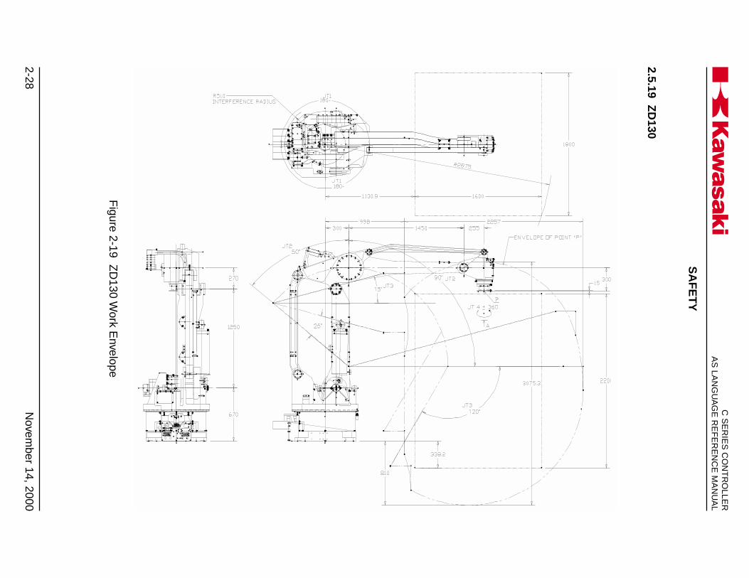
2.5.19 ZD
130
Figure 2-19 Z
D130 W
ork Envelope

SA
FE
TY
2-29N
ovember 14, 2000
Ka
aa
ws
kC
SE
RIE
S C
ON
TR
OLLE
RA
S LA
NG
UA
GE
RE
FE
RE
NC
E M
AN
UA
L
Figure 2-20 Z
X130L W
ork Envelope
2.5.20 ZX
130L
SA
FE
TY
C S
ER
IES
CO
NT
RO
LLER
AS
LAN
GU
AG
E R
EF
ER
EN
CE
MA
NU
AL
2-30N
ovember 14, 2000
Ka
aa
ws
k
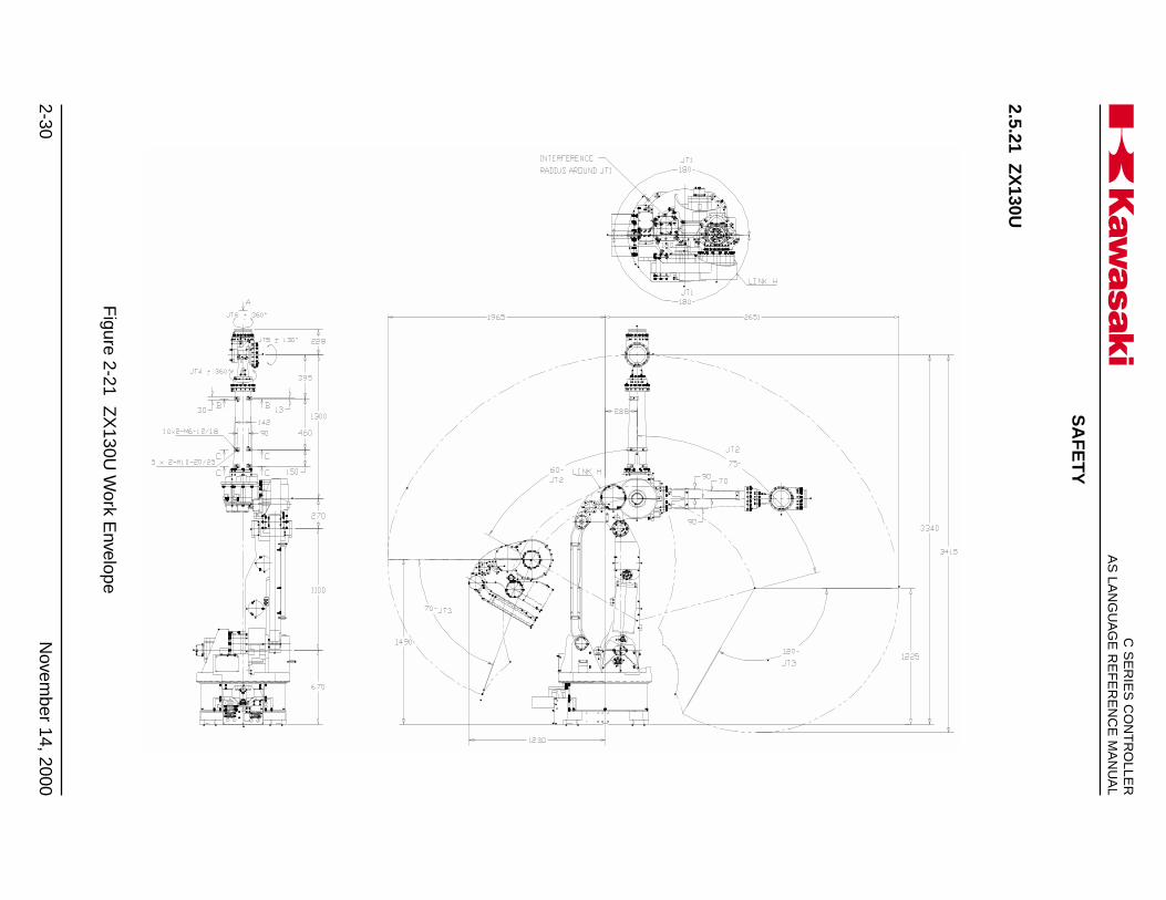
Figure 2-21 Z
X130U
Work E
nvelope
2.5.21 ZX
130U
SA
FE
TY
2-31N
ovember 14, 2000
Ka
aa
ws
kC
SE
RIE
S C
ON
TR
OLLE
RA
S LA
NG
UA
GE
RE
FE
RE
NC
E M
AN
UA
L
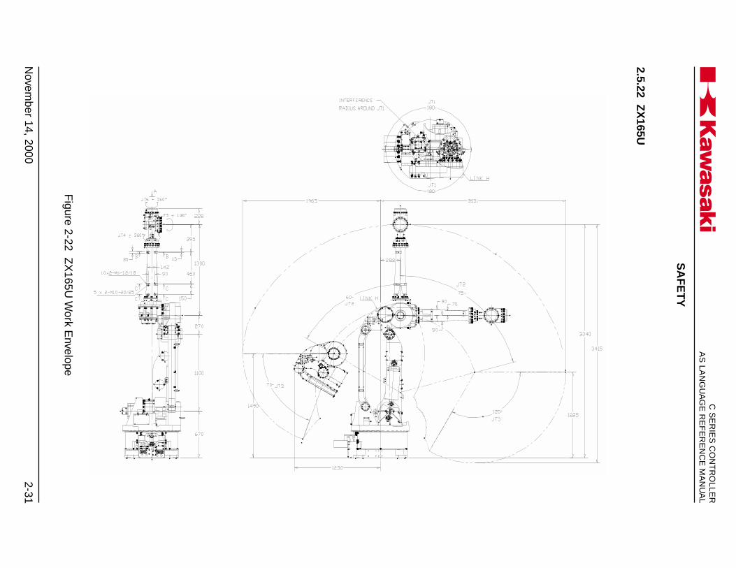
2.5.22 ZX
165U
Figure 2-22 Z
X165U
Work E
nvelope
SA
FE
TY
C S
ER
IES
CO
NT
RO
LLER
AS
LAN
GU
AG
E R
EF
ER
EN
CE
MA
NU
AL
2-32N
ovember 14, 2000
Ka
aa
ws
k
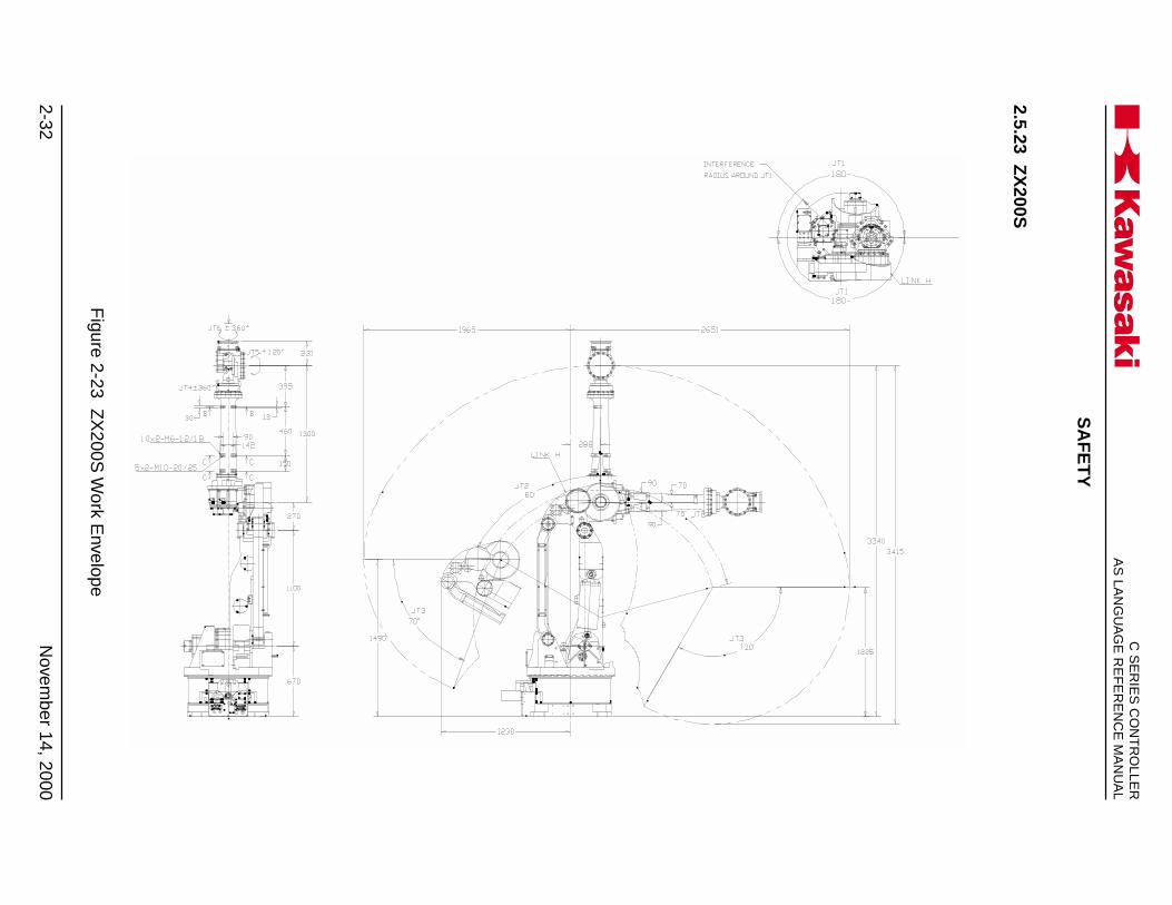
2.5.23 ZX
200S
Figure 2-23 Z
X200S
Work E
nvelope
SA
FE
TY
2-33N
ovember 14, 2000
Ka
aa
ws
kC
SE
RIE
S C
ON
TR
OLLE
RA
S LA
NG
UA
GE
RE
FE
RE
NC
E M
AN
UA
L
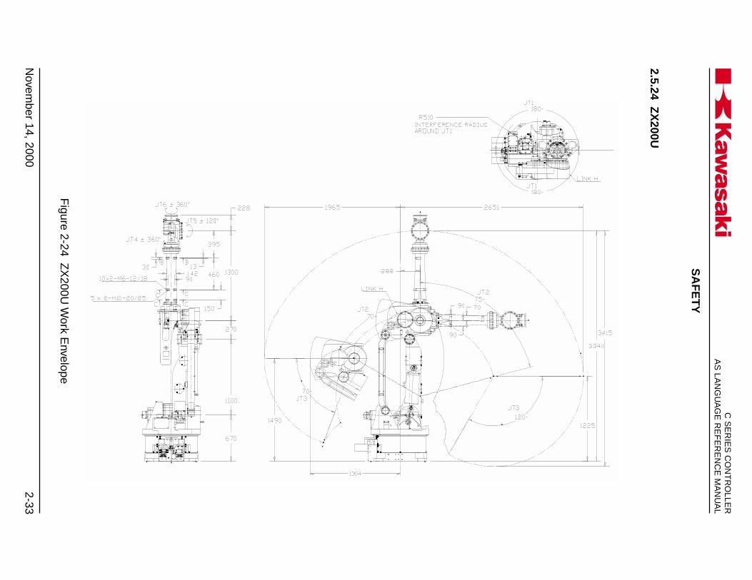
2.5.24 ZX
200U
Figure 2-24 Z
X200U
Work E
nvelope

SA
FE
TY
C S
ER
IES
CO
NT
RO
LLER
AS
LAN
GU
AG
E R
EF
ER
EN
CE
MA
NU
AL
2-34N
ovember 14, 2000
Ka
aa
ws
k
2.5.25 ZX
300S
Figure 2-25 Z
X300S
Work E
nvelope

POWER ON/OFF PROCEDURES
3-1November 20, 1998
C SERIES CONTROLLERAS LANGUAGE REFERENCE MANUALKa a aw s k
3.0 POWER ON/OFF PROCEDURES ..................................................................... 3-23.1 Controller Power On/Off Procedures .................................................................. 3-23.1.1 Controller Power On Procedures ....................................................................... 3-23.1.2 Controller Power Off Procedures ....................................................................... 3-23.2 Servo Motor Power-On Procedures ................................................................... 3-73.2.1 Servo Motor Power-On in the Repeat Mode ...................................................... 3-73.2.2 Servo Motor Power-On in the Teach Mode......................................................... 3-73.3 Methods for Stopping the Robot ........................................................................ 3-83.3.1 Emergency Stop Switch ..................................................................................... 3-83.3.2 HOLD/RUN Switch ............................................................................................. 3-83.3.3 TEACH/REPEAT Switch .................................................................................... 3-8

POWER ON/OFF PROCEDURES
C SERIES CONTROLLERAS LANGUAGE REFERENCE MANUAL
3-2 November 14, 2000
Ka a aw s k
3.0 POWER ON/OFF PROCEDURES
This unit provides the power ON/OFF procedures for the robot controller and servomotors. Refer to figures 3-1 through 3-7 during these procedures.
3.1 CONTROLLER POWER ON/OFF PROCEDURES
3.1.1 CONTROLLER POWER ON PROCEDURES
1. Ensure all personal are clear of the work cell and all safety devices are in place andoperational.
2. Turn the HOLD/RUN switch to the HOLD position.
3. Place the controller main disconnect switch in the ON position. At this time theCONTROL POWER indicator lamp illuminates.
3.1.2 CONTROLLER POWER OFF PROCEDURES
1. Turn the HOLD/RUN switch to the HOLD position; the robot decelerates to a stopand the MOTOR POWER lamp turns off.
2. Press the EMERGENCY STOP switch. At this time the CYCLE START lamp turnsoff.
3. Place the controller main disconnect switch in the OFF position.
POWER ON/OFF PROCEDURES
3-3November 20, 1998
C SERIES CONTROLLERAS LANGUAGE REFERENCE MANUALKa a aw s k
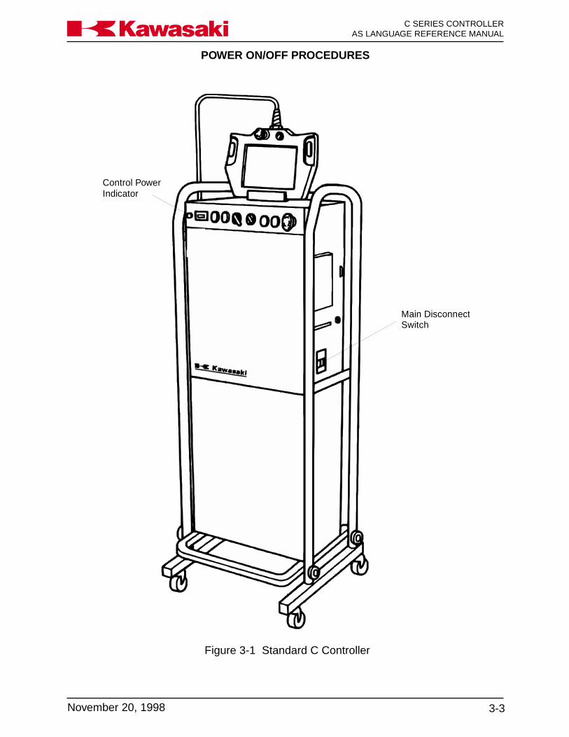
Control PowerIndicator
Main DisconnectSwitch
Figure 3-1 Standard C Controller

POWER ON/OFF PROCEDURES
C SERIES CONTROLLERAS LANGUAGE REFERENCE MANUAL
3-4 November 20, 1998
Ka a aw s k
Figure 3-2 North American C Controller

POWER ON/OFF PROCEDURES
3-5November 20, 1998
C SERIES CONTROLLERAS LANGUAGE REFERENCE MANUALKa a aw s k
Figure 3-3 European C Controller
POWER ON/OFF PROCEDURES
C SERIES CONTROLLERAS LANGUAGE REFERENCE MANUAL
3-6 November 20, 1998
Ka a aw s k
HOLD RUN TEACH REPEAT CYCLE STARTERROR RESET MOTOR POWERERROR EMERGENCY STOP
HOUR METER
CONTROLPOWER
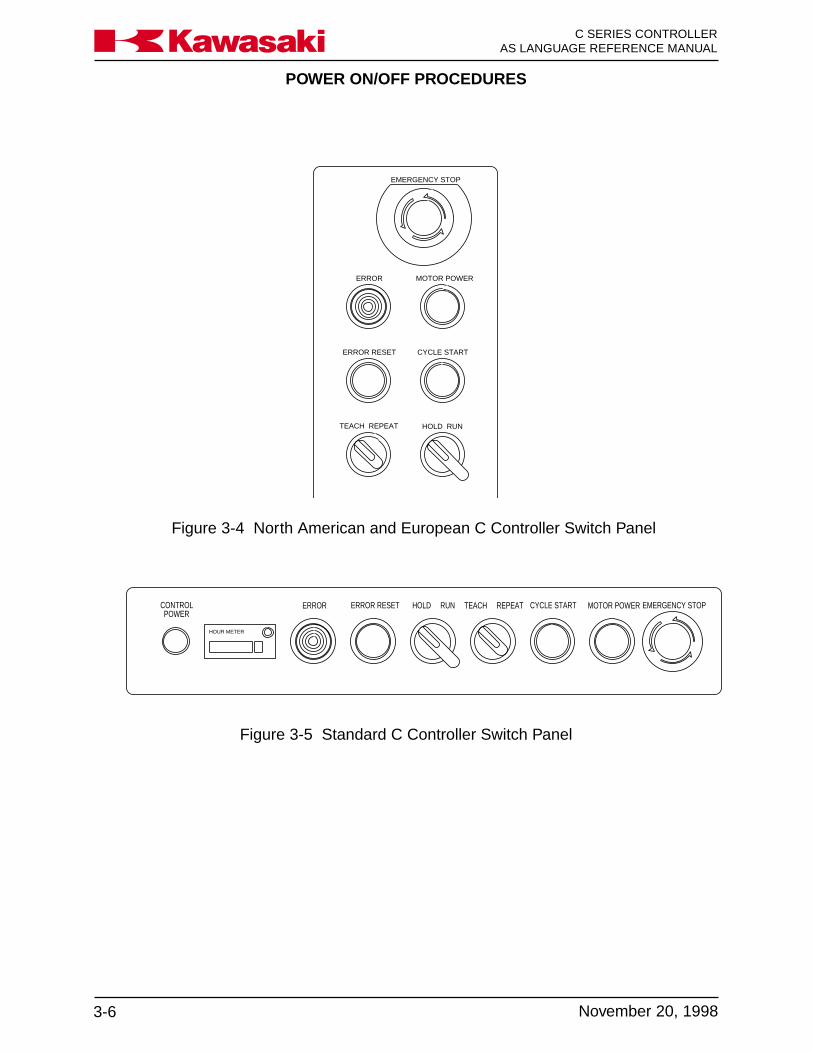
Figure 3-5 Standard C Controller Switch Panel
Figure 3-4 North American and European C Controller Switch Panel
HOLD RUN TEACH REPEAT
CYCLE STARTERROR RESET
MOTOR POWERERROR
EMERGENCY STOP
POWER ON/OFF PROCEDURES
3-7November 14, 2000
C SERIES CONTROLLERAS LANGUAGE REFERENCE MANUALKa a aw s k
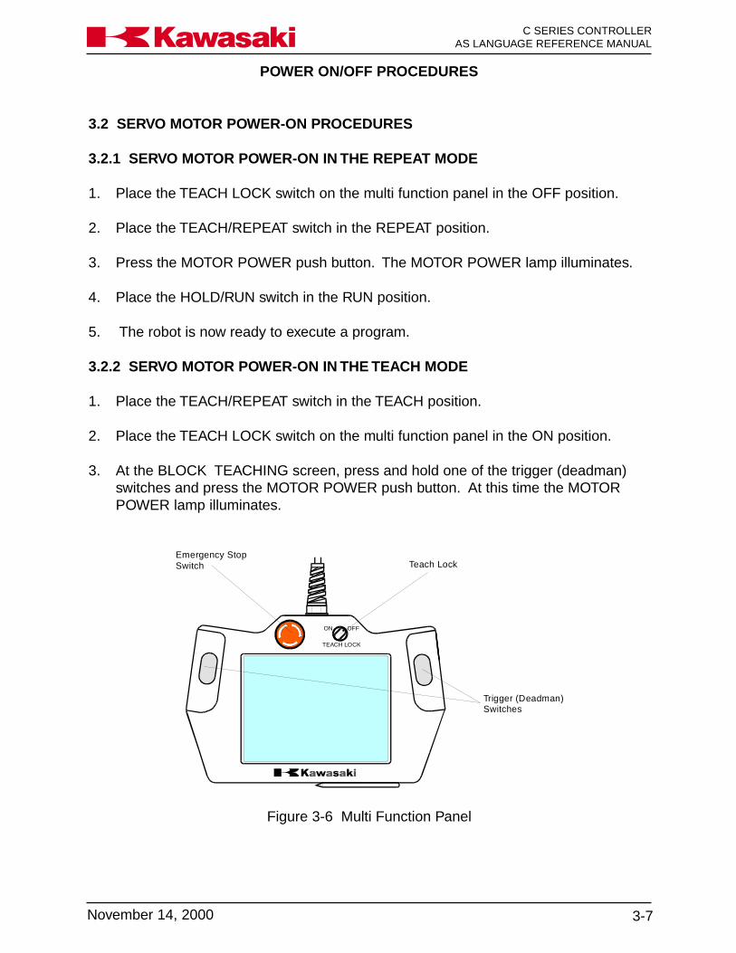
Figure 3-6 Multi Function Panel
ON OFF
TEACH LOCK
Teach Lock
Trigger (Deadman)Switches
Emergency StopSwitch
3.2 SERVO MOTOR POWER-ON PROCEDURES
3.2.1 SERVO MOTOR POWER-ON IN THE REPEAT MODE
1. Place the TEACH LOCK switch on the multi function panel in the OFF position.
2. Place the TEACH/REPEAT switch in the REPEAT position.
3. Press the MOTOR POWER push button. The MOTOR POWER lamp illuminates.
4. Place the HOLD/RUN switch in the RUN position.
5. The robot is now ready to execute a program.
3.2.2 SERVO MOTOR POWER-ON IN THE TEACH MODE
1. Place the TEACH/REPEAT switch in the TEACH position.
2. Place the TEACH LOCK switch on the multi function panel in the ON position.
3. At the BLOCK TEACHING screen, press and hold one of the trigger (deadman)switches and press the MOTOR POWER push button. At this time the MOTORPOWER lamp illuminates.

POWER ON/OFF PROCEDURES
C SERIES CONTROLLERAS LANGUAGE REFERENCE MANUAL
3-8 November 14, 2000
Ka a aw s k
3.3 METHODS FOR STOPPING THE ROBOT
One of three methods are used to stop robot motion. Each of these methods is de-scribed in the following sections.
3.3.1 EMERGENCY STOP SWITCH
When the EMERGENCY STOP switch is pressed, motor power is turned off and thebrakes are applied stopping the robot immediately. This places very high loads upon therobot and is only recommended for emergency situations. To stop the robot during non-emergency situations refer to section 3.3.2, HOLD/RUN SWITCH.
3.3.2 HOLD/RUN SWITCH
When the HOLD/RUN switch is turned to the HOLD position the robot deceleratessmoothly to a stop and the brakes are applied. This places the robot into a temporarystop condition. The motor power lamp turns OFF and the CYCLE START lamp remainsON. When the HOLD/RUN switch is again turned to the RUN position the robot contin-ues the motion execution prior to HOLD. To create a permanent stop condition, pressthe EMERGENCY STOP switch or turn the TEACH/REPEAT switch to the TEACHposition (the CYCLE START and MOTOR POWER indicator lamps turn off).
3.3.3 TEACH/REPEAT SWITCH
When the TEACH/REPEAT switch is turned to the TEACH position motor power isturned off and the brakes are applied stopping the robot immediately. This places veryhigh loads upon the robot and is only recommended for emergency situations. To stopthe robot during non-emergency situations refer to section 3.3.2, HOLD/RUN SWITCH.

AS LANGUAGE COMMANDS
4-1November 14, 2000
Ka a aw s k C SERIES CONTROLLERAS LANGUAGE REFERENCE MANUAL
4.0 MONITOR AND EDITOR COMMANDS ........................................................ 4-34.1 Keyboard Display Control .............................................................................. 4-44.1.1 Terminal Control ............................................................................................ 4-44.2 Editor Commands ......................................................................................... 4-54.3 Program and Data Control Commands ....................................................... 4-144.3.1 DIRECTORY Commands ............................................................................ 4-154.3.2 LIST Commands ......................................................................................... 4-174.3.3 DELETE Commands ................................................................................... 4-194.3.4 RENAME Command ................................................................................... 4-204.3.5 XFER and COPY commands ...................................................................... 4-214.4 Program and Data Storage Commands ...................................................... 4-224.4.1 FORMAT and FDIRECTORY Commands ................................................... 4-234.4.2 SAVE Command ......................................................................................... 4-234.4.3 LOAD and FDELETE Commands ............................................................... 4-254.5 Program Control .......................................................................................... 4-264.5.1 SPEED and PRIME Commands ................................................................. 4-264.5.2 EXECUTE, STEP, and MSTEP Commands................................................ 4-284.5.3 ABORT, HOLD, CONTINUE, and STPNEXT Commands ........................... 4-304.5.4 KILL and DO Commands ............................................................................ 4-314.6 Defining Locations, Limits, and Home Positions ......................................... 4-314.6.1 Here, Teach, and Point Commands............................................................. 4-324.6.2 TOOL and BASE Commands ..................................................................... 4-364.6.3 ULIMIT and LLIMIT Commands .................................................................. 4-394.6.4 SETHOME Command ................................................................................. 4-404.6.5 WHERE Command ..................................................................................... 4-414.7 System Information ..................................................................................... 4-434.7.1 ERRLOG and OPLOG Commands ............................................................. 4-434.7.2 STATUS, FREE, ID, and HELP Commands ................................................ 4-444.8 System Control ........................................................................................... 4-474.8.1 SYSINIT, TIME, and ERESET Commands ................................................. 4-474.8.2 SWITCH, HSETCLAMP, and ZSIGSPEC Commands ................................ 4-484.8.3 ZZERO Command ...................................................................................... 4-494.8.4 BATCHK, ENCCHK_EMG, and ENCCHK_PON Commands ..................... 4-514.8.5 SLOW_REPEAT, REC_ACCEPT, ENV_DATA, and ENV2_DATA
Commands .................................................................................................. 4-524.8.6 CHSUM Command ..................................................................................... 4-554.9 Signal Commands ....................................................................................... 4-564.9.1 SIGNAL, PULSE, DLYSIG, and BITS Commands ...................................... 4-564.9.2 I/O and RESET Commands ........................................................................ 4-584.9.3 DEFSIG Command ..................................................................................... 4-604.10 Z-Series Robots AS Language Commands ................................................ 4-624.10.1 1GV Arm ID Board Functions and Commands ........................................... 4-624.10.2 Failure Prediction Function, Aux 124 (Option) ............................................ 4-654.10.2.1 Failure Prediction Function Setup Procedure.............................................. 4-65
AS LANGUAGE COMMANDS
C SERIES CONTROLLERAS LANGUAGE REFERENCE MANUAL
4-2 November 14, 2000
Ka a aw s k
4.10.3 Collision Detection Function ..................................................................... 4-664.10.3.1 Setting Tool Weight Data Using AS Language WEIGHT Command ....... 4-664.10.3.2 Range of Threshold .................................................................................. 4-674.10.3.3 Setting Thresholds .................................................................................... 4-684.10.3.4 Collision Detection AS Language Commands.......................................... 4-734.10.3.5 COLR ....................................................................................................... 4-744.10.3.6 COLRON/OFF .......................................................................................... 4-764.10.3.7 COLRJ ...................................................................................................... 4-774.10.3.8 COLRJON/OFF ........................................................................................ 4-784.10.3.9 COLT ........................................................................................................ 4-784.10.3.10 COLTON/OFF ........................................................................................... 4-784.10.3.11 COLTJ ...................................................................................................... 4-794.10.3.12 COLTJON/OFF ......................................................................................... 4-794.10.3.13 COLMVON/OFF ....................................................................................... 4-804.10.3.14 COLCALON/OFF...................................................................................... 4-814.10.3.15 WEIGHT ................................................................................................... 4-814.10.3.16 SETCOLTHID ........................................................................................... 4-824.10.3.17 COLINIT ................................................................................................... 4-834.10.3.18 COLSTATE ............................................................................................... 4-834.10.3.19 Collision Detection Error Code ................................................................. 4-854.10.3.20 Collision Detection Troubleshooting .......................................................... 4-85

AS LANGUAGE COMMANDS
4-3November 14, 2000
Ka a aw s k C SERIES CONTROLLERAS LANGUAGE REFERENCE MANUAL
4.0 MONITOR AND EDITOR COMMANDS
The AS system is operational as soon as power is applied to the controller. To accessthe MONITOR mode, press the menu key and select the keyboard screen (Figure 4-1).
Figure 4-1 Keyboard Screen

AS LANGUAGE COMMANDS
C SERIES CONTROLLERAS LANGUAGE REFERENCE MANUAL
4-4 November 14, 2000
Ka a aw s k
4.1 KEYBOARD DISPLAY CONTROL
CTL+L/CTL+N The CTL+L/CTL+N (last/next) key enables the programmer todisplay the contents of the last line entered to appear on the currentline or change the the current line to the next (CTL+N) one in orderof lines after the CTL+L key is used. The CTL+N key is only effec-tive after CTL+L is used more than once.
CTL+L is available with the keyboard in the normal mode andCTRL+N is available with the keyboard in the shifted mode (Figure4-1).
4.1.1 TERMINAL CONTROL
The following terminal control commands are available for AS Language programmingusing the keyboard of a personal computer (PC) interfaced with the C controller (seeunit 8):
CTRL C This command cancels the current input line. It is not used toterminate the program that is currently executing. This command issimilar to pressing the EXIT key on the multi function panel key-board.
CTRL L This command enables the contents of the line of code previouslyentered to display on the current input line. This operation can beused up to seven times to recover previously entered data.
CTRL N The CTRL N command is used in conjunction with the CTRL Lcommand. The CTRL N command changes the contents of thecurrent input line to the next one in the history of command inputsafter the CTRL L command is used. This operation is effective afterCTRL L is pressed more than once.
CTRL Q This command is used to resume the updating of displayed informa-tion after it was stopped with a CTRL S command.
CTRL S Stops the scrolling of output information displayed. This commandis used to confirm output information. Output resumes when CTRLQ is entered.

AS LANGUAGE COMMANDS
4-5November 14, 2000
Ka a aw s k C SERIES CONTROLLERAS LANGUAGE REFERENCE MANUAL
The program that is executing cannot be edited or de-leted. Program commands or instructions are entered inlowercase or uppercase characters. When listing or ed-iting the program, keywords are displayed in uppercasecharacters
NOTE
4.2 EDITOR COMMANDS
Editor commands are used after accessing the editor mode. The user must type “edit”in the MONITOR mode followed by the name of the program to edit or a new programname.
ED program_name,stepEDIT
program_name: Name of the program to edit. If the program does not exist, a newprogram is created. If a program name is not specified, then thelast program edited is opened for editing.
step: Optional step number to start editing. If the step is not specified,editing starts at the first step or the last step edited. If an erroroccurred during the last program run, the step where the erroroccurred is selected.

AS LANGUAGE COMMANDS
C SERIES CONTROLLERAS LANGUAGE REFERENCE MANUAL
4-6 November 14, 2000
Ka a aw s k
S step_numberSTEP
The number of the step to edit. If the step number is not specified,the first step is selected. If the step number is greater than thenumber of steps in the program, a new step following the last re-corded step in the program is selected.
P step_countPRINT
The number of steps to display beginning with the current step. Ifthe step number is not specified, only one step is displayed.
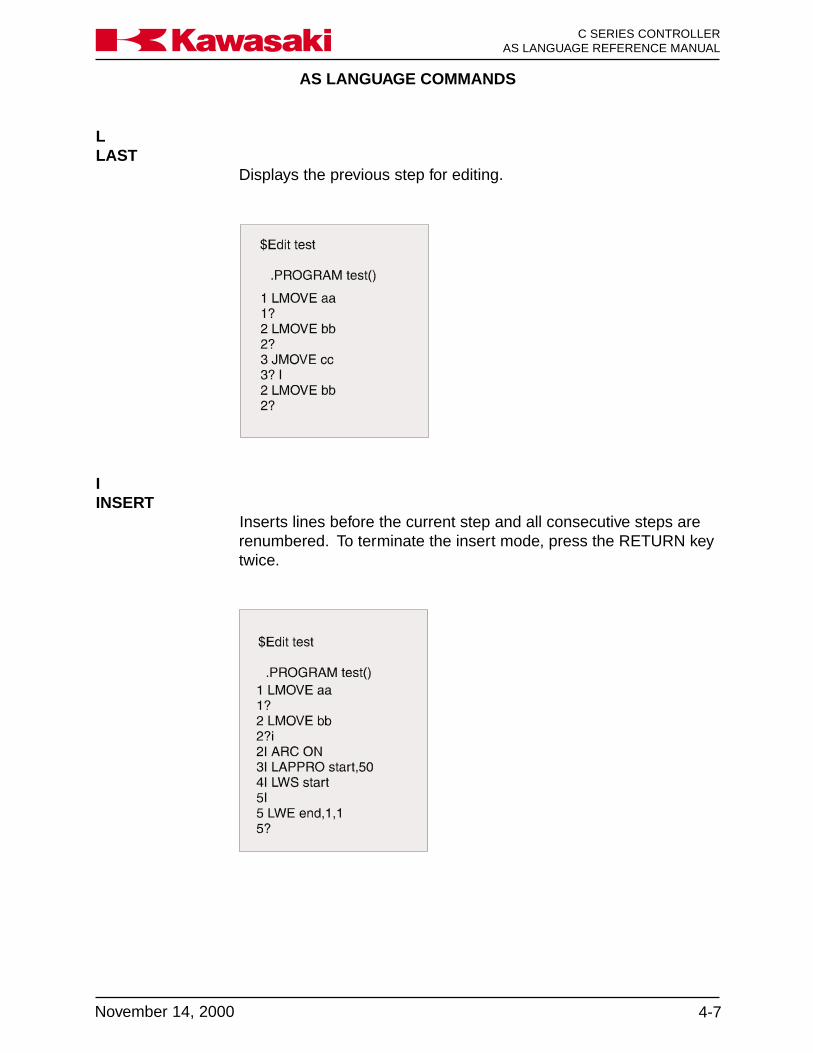
AS LANGUAGE COMMANDS
4-7November 14, 2000
Ka a aw s k C SERIES CONTROLLERAS LANGUAGE REFERENCE MANUAL
LLAST
Displays the previous step for editing.
IINSERT
Inserts lines before the current step and all consecutive steps arerenumbered. To terminate the insert mode, press the RETURN keytwice.

AS LANGUAGE COMMANDS
C SERIES CONTROLLERAS LANGUAGE REFERENCE MANUAL
4-8 November 14, 2000
Ka a aw s k
D step_countDELETE
Deletes program steps beginning with the current step. All con-secutive steps are renumbered. The step_count specifies thenumber of steps to delete beginning with the current step. If thestep count is not entered, the current step is deleted.
F character_stringFIND
Searches the current program for the specified character_stringfrom the current step to the last, and displays the first step thatincludes the string.

AS LANGUAGE COMMANDS
4-9November 14, 2000
Ka a aw s k C SERIES CONTROLLERAS LANGUAGE REFERENCE MANUAL
M /existing_characters/new_charactersMODIFY
Modifies the current step by replacing the existing characters speci-fied with the new characters specified.
/existing_characters: Characters to modify in the current step.
/new_characters: Characters used to modify the existing characters.
OOVER
Places the cursor on the current step for editing.
Use the arrow keys to move the cursor within the step. The Back-space key removes the character preceding the cursor.
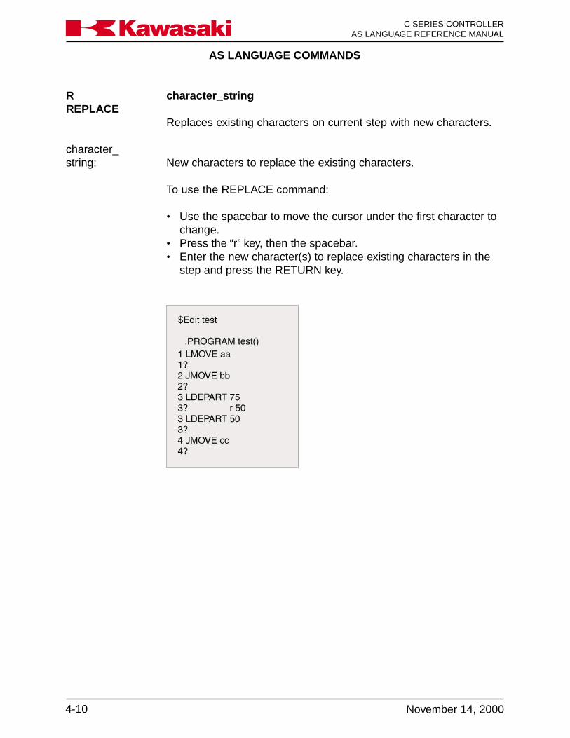
AS LANGUAGE COMMANDS
C SERIES CONTROLLERAS LANGUAGE REFERENCE MANUAL
4-10 November 14, 2000
Ka a aw s k
R character_stringREPLACE
Replaces existing characters on current step with new characters.
character_string: New characters to replace the existing characters.
To use the REPLACE command:
• Use the spacebar to move the cursor under the first character tochange.
• Press the “r” key, then the spacebar.• Enter the new character(s) to replace existing characters in the
step and press the RETURN key.

AS LANGUAGE COMMANDS
4-11November 14, 2000
Ka a aw s k C SERIES CONTROLLERAS LANGUAGE REFERENCE MANUAL
EEXIT
Exits from the editor to the monitor mode.
C program_name, step_numberCHANGE
Opens the selected program for editing at the specified step

AS LANGUAGE COMMANDS
C SERIES CONTROLLERAS LANGUAGE REFERENCE MANUAL
4-12 November 14, 2000
Ka a aw s k
XD number of linesCUT
The XD command is used to remove (cut) a specified number oflines froma program and store them in the paste buffer.
Move the cursor to the first line to remove to the paste buffer andenter XD, the number of lines to cut, and press ENTER.
The number of lines specified, including the current line, are placedin the paste buffer and the program steps are renumbered accord-ingly.
When the XD command is used again, the contents of the pastebuffer are overwritten.
XY number of linesCOPY
The XY command is used to copy a specified number of lines froma program and store them in the paste buffer.
Move the cursor to the first line to copy to the paste buffer and enterXY, the number of lines to copy, and press ENTER.
The number of lines specified, including the current line, are placedin the paste buffer.
When the XY command is used the lines in the program are notaffected.
XPPASTE
Places the contents of the paste buffer into a program.
The steps in the paste buffer are placed in the program ahead ofthe step number where the XP command is entered.
The program steps are renumbered accordingly.

AS LANGUAGE COMMANDS
4-13November 14, 2000
Ka a aw s k C SERIES CONTROLLERAS LANGUAGE REFERENCE MANUAL
XQ Places the contents of the paste buffer into a program in reversePASTE order.
The steps in the paste buffer are placed in the program ahead ofthe step number where the XQ command is entered.
The program steps are renumbered accordingly.
XS Displays the contents of the paste buffer.DISPLAY
The XS command entered at step 2 displays the three steps in thepaste buffer.

AS LANGUAGE COMMANDS
C SERIES CONTROLLERAS LANGUAGE REFERENCE MANUAL
4-14 November 14, 2000
Ka a aw s k
4.3 PROGRAM AND DATA CONTROL COMMANDS
DIRECTORY Displays the names of all programs and variables.
DIRECTORY/P Displays the names of programs.
DIRECTORY/L Displays the names of locations.
DIRECTORY/R Displays the names of real variables.
DIRECTORY/S Displays the names of string variables.
LIST Displays all program steps and variable values.
LIST/P Displays all program steps.
LIST/L Displays the value of specified locations.
LIST/R Displays the value of specified real variables.
LIST/S Displays the value of specified string variables.
DELETE Deletes specified programs and related variables.
DELETE/P Deletes specified programs.
DELETE/L Deletes specified locations.
DELETE/R Deletes specified real variables.
DELETE/S Deletes specified string variables.
RENAME Changes the name of a program.
XFER Copies steps from one program to another.
COPY Copies one or more programs to a new program.

AS LANGUAGE COMMANDS
4-15November 14, 2000
Ka a aw s k C SERIES CONTROLLERAS LANGUAGE REFERENCE MANUAL
4.3.1 DIRECTORY COMMANDS
The DIRECTORY commands display the names of programs and variables residing inmemory. If a program name is not specified when using the DIRECTORY command, allprogram names, location names, real variable names, and string variable names arelisted. The screen stops at the end of each page until the spacebar is pressed, andcontinues to do so until all names have been listed. Pressing the ENTER key stops thelisting.
The asterisk “*” is a wild card character which represents any character. It is used withall program and data control commands except the RENAME command. The followingillustration shows how the asterisk is used to list specific information. For example, ifDIR w* is typed, all programs beginning with “w” and subroutine programs called by theselected programs are listed. All locations and real variables used in the programs aredisplayed.
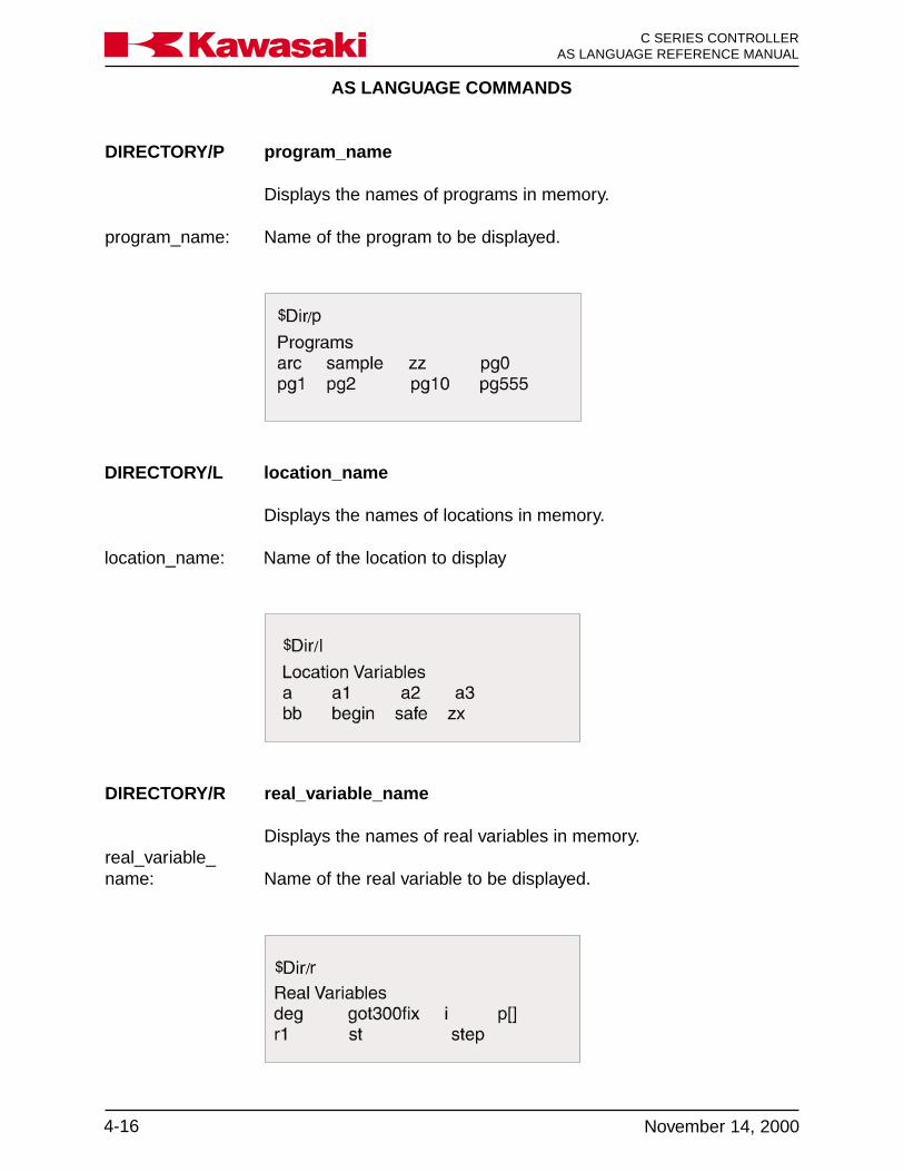
AS LANGUAGE COMMANDS
C SERIES CONTROLLERAS LANGUAGE REFERENCE MANUAL
4-16 November 14, 2000
Ka a aw s k
DIRECTORY/P program_name
Displays the names of programs in memory.
program_name: Name of the program to be displayed.
DIRECTORY/L location_name
Displays the names of locations in memory.
location_name: Name of the location to display
DIRECTORY/R real_variable_name
Displays the names of real variables in memory.real_variable_name: Name of the real variable to be displayed.

AS LANGUAGE COMMANDS
4-17November 14, 2000
Ka a aw s k C SERIES CONTROLLERAS LANGUAGE REFERENCE MANUAL
DIRECTORY/S string_variable_name
Displays the names of string variables in memory.string_variable_name: Name of the string variable to be displayed.
4.3.2 LIST COMMANDS
The LIST command displays program steps and the values of variables residing inmemory. If a name is not specified when using the LIST command, all program names,location names, real variable names, and string variable names are listed. The screenstops at the end of the page until the spacebar is pressed and continues until all nameshave been listed.
LIST/P program_name
Displays all program steps.
program_name: Name of the program to be listed.
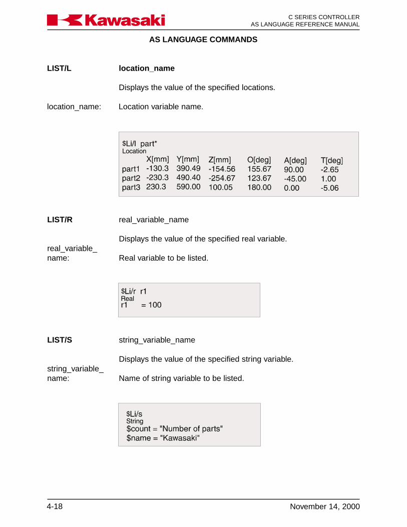
AS LANGUAGE COMMANDS
C SERIES CONTROLLERAS LANGUAGE REFERENCE MANUAL
4-18 November 14, 2000
Ka a aw s k
LIST/L location_name
Displays the value of the specified locations.
location_name: Location variable name.
LIST/R real_variable_name
Displays the value of the specified real variable.real_variable_name: Real variable to be listed.
LIST/S string_variable_name
Displays the value of the specified string variable.string_variable_name: Name of string variable to be listed.
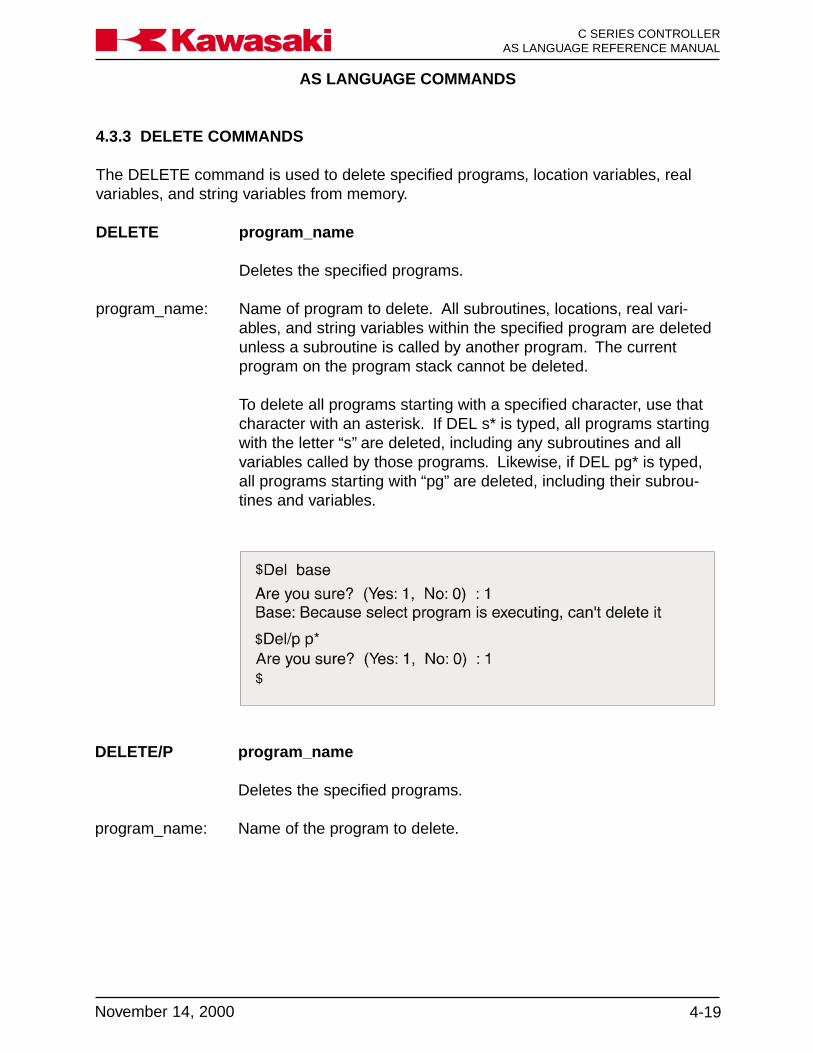
AS LANGUAGE COMMANDS
4-19November 14, 2000
Ka a aw s k C SERIES CONTROLLERAS LANGUAGE REFERENCE MANUAL
DELETE/P program_name
Deletes the specified programs.
program_name: Name of the program to delete.
4.3.3 DELETE COMMANDS
The DELETE command is used to delete specified programs, location variables, realvariables, and string variables from memory.
DELETE program_name
Deletes the specified programs.
program_name: Name of program to delete. All subroutines, locations, real vari-ables, and string variables within the specified program are deletedunless a subroutine is called by another program. The currentprogram on the program stack cannot be deleted.
To delete all programs starting with a specified character, use thatcharacter with an asterisk. If DEL s* is typed, all programs startingwith the letter “s” are deleted, including any subroutines and allvariables called by those programs. Likewise, if DEL pg* is typed,all programs starting with “pg” are deleted, including their subrou-tines and variables.
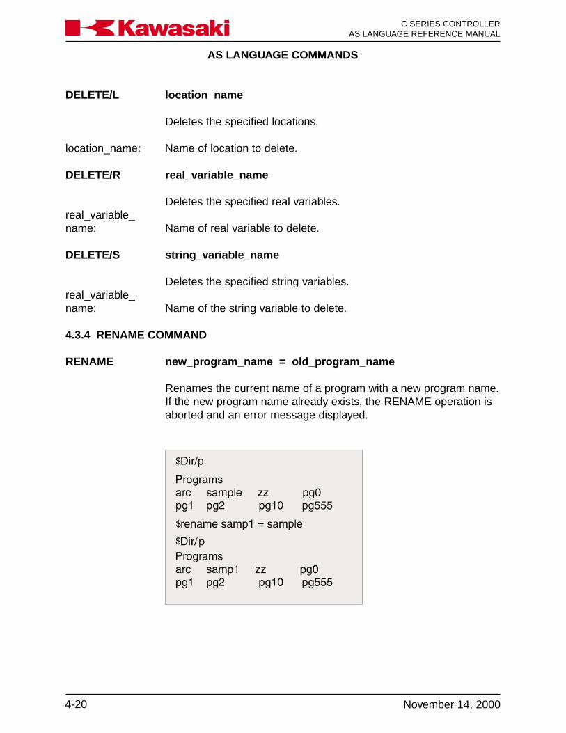
AS LANGUAGE COMMANDS
C SERIES CONTROLLERAS LANGUAGE REFERENCE MANUAL
4-20 November 14, 2000
Ka a aw s k
DELETE/L location_name
Deletes the specified locations.
location_name: Name of location to delete.
DELETE/R real_variable_name
Deletes the specified real variables.real_variable_name: Name of real variable to delete.
DELETE/S string_variable_name
Deletes the specified string variables.real_variable_name: Name of the string variable to delete.
4.3.4 RENAME COMMAND
RENAME new_program_name = old_program_name
Renames the current name of a program with a new program name.If the new program name already exists, the RENAME operation isaborted and an error message displayed.
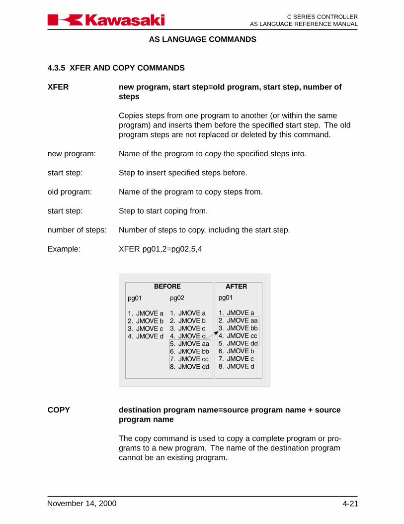
AS LANGUAGE COMMANDS
4-21November 14, 2000
Ka a aw s k C SERIES CONTROLLERAS LANGUAGE REFERENCE MANUAL
4.3.5 XFER AND COPY COMMANDS
XFER new program, start step=old program, start step, number ofsteps
Copies steps from one program to another (or within the sameprogram) and inserts them before the specified start step. The oldprogram steps are not replaced or deleted by this command.
new program: Name of the program to copy the specified steps into.
start step: Step to insert specified steps before.
old program: Name of the program to copy steps from.
start step: Step to start coping from.
number of steps: Number of steps to copy, including the start step.
Example: XFER pg01,2=pg02,5,4
COPY destination program name=source program name + sourceprogram name
The copy command is used to copy a complete program or pro-grams to a new program. The name of the destination programcannot be an existing program.

AS LANGUAGE COMMANDS
C SERIES CONTROLLERAS LANGUAGE REFERENCE MANUAL
4-22 November 14, 2000
Ka a aw s k
4.4 PROGRAM AND DATA STORAGE COMMANDS
FORMAT Initializes a PC card or a floppy disk.
FDIRECTORY Displays the name of files stored on a PC card or a disk.
SAVE Stores programs and variables in a specified file on a PC card or adisk.
SAVE/P Stores programs in a specified file on a PC card or a disk.
SAVE/L Stores locations in a specified file on a PC card or a disk.
SAVE/R Stores real variables in a specified file on a PC card or a disk.
SAVE/S Stores string variables in a specified file on a PC card or a disk.
SAVE/SYS Stores system data in a specified file on a PC card or a disk.
SAVE/ELOG Stores error log data in a specified file on a PC card or a disk.
LOAD Loads programs and variables from a specified file into systemmemory.
LOAD/Q Loads selected programs and variables from a specified file intosystem memory.
FDELETE Deletes specified files on a PC card or a disk.

AS LANGUAGE COMMANDS
4-23November 14, 2000
Ka a aw s k C SERIES CONTROLLERAS LANGUAGE REFERENCE MANUAL
4.4.1 FORMAT AND FDIRECTORY COMMANDS
FORMAT Initializes a PC card or a disk to accept files. The format commanderases all data on a PC card or a disk. It also sets up a directory forkeeping track of files as they are created. A new PC card or diskmust be formatted before it can be used.
FDIRECTORY Displays names of files stored on the PC card or disk. The exten-sions indicate the type of file, such as system (AS), programs (PG),auxiliary (AU), location variables (LC), real variables (RV), weld data(WD), and string variables (ST). It also displays the size of the file,and the date and time the file was created.
4.4.2 SAVE COMMAND
SAVE file_name=program_name
Stores programs and variables in a specified file onto a PC card ora disk.
file_name: Name of the file in which all programs, locations, and variables arestored.
program_name: Name of the program stored in the specified file directory. If thename of the program is not specified, all data in memory is stored.
If a file with the same name already exists a “B” (backup) is addedto the extension of the existing file. For example, if a file namedTEST.AS exists on disk, and a backup is made to the PC card ordisk using the same file name, the file extension is changed toTEST.BAS and a new file TEST.AS is created.

AS LANGUAGE COMMANDS
C SERIES CONTROLLERAS LANGUAGE REFERENCE MANUAL
4-24 November 14, 2000
Ka a aw s k
SAVE/P file_name=program_name
Stores programs in a specified file on a PCcard or a disk.
file_name: Name of the file in which programs are stored.
program_name: Name of the program to store in the specified file directory. If thename of the program is not specified, all programs in memory arestored. If the file name has no extension, PG is added.
Example: SAVE/P FENDER = pg01, weld, pg02 saves programs pg01, weld,and pg02 in the file FENDER.
SAVE/L file_name=program_name
Stores locations in a specified file on a PC card or a disk.
file_name: Name of the file in which locations are stored.
program_name: Name of the program to store in the specified file directory. If thename of the program is not specified, all locations from memory arestored. If the file name has no extension, LC is added.
Example: SA/L #POS saves all precision points in the file #POS.
SAVE/R file_name=program_name
Stores real variables in a specified file on a PC card or a disk.
file_name: Name of the file in which real variables are stored.
program_name: Name of the program to store in the specified file directory. If thename of the program is not specified, all real variables from memoryare stored. If the file name has no extension, RV is added.
Example: SA/R REAL_VAR saves all real values in the file REAL_VAR.

AS LANGUAGE COMMANDS
4-25November 14, 2000
Ka a aw s k C SERIES CONTROLLERAS LANGUAGE REFERENCE MANUAL
SAVE/S file_name=program_name
Stores character string variables in a specified file on a PC card ora disk.
file_name: Name of the file in which string variables are stored.
program_name: Name of the program store in the specified file directory. If thename of the program is not specified, all string variables frommemory are stored. If the file name has no extension, .ST is added.
Example: SA/S MESSAGES saves all string variables in the file MESSAGES.
SAVE/SYS file_name
Stores system data in a specified file on a PC card or a disk.
file_name: Name of the file in which system data is stored with an .SY exten-sion.
SAVE/ELOG file_name
Stores system data in a specified file on a PC card or a disk.
file_name: Name of the file in which error log data is stored with an .EL exten-sion.
4.4.3 LOAD AND FDELETE COMMANDS
LOAD file_name
Loads programs and variables from a specified file into systemmemory.
file_name: Name of file to load from disk to memory. If an extension is notspecified, .AS is assumed. All data in the specified file is loaded.
LOAD/Q file_name
Loads selected programs and variables from a specified file intosystem memory. The user is prompted “Load this data? (1:Yes,0:No, 2:Load all, 3:Exit)” before each type of data is loaded.
AS LANGUAGE COMMANDS
C SERIES CONTROLLERAS LANGUAGE REFERENCE MANUAL
4-26 November 14, 2000
Ka a aw s k
file_name: Name of file to load from the PC card to memory. If an extension isnot specified, .AS is assumed. All selected data in the specified fileis loaded.
An error message is displayed if a porgram in the file selected to load already exists inmemory. If a variable is loaded from a file to memory and a variable of the same typeand same name exists the old value is lost and the new value is stored. When systemsettings are loaded from a file the settings in memory are overwritten.
FDELETE file_name
Deletes specified files from a PC card or a disk.
file_name: Name of file to delete. When a file is deleted, its name and data areremoved from the directory, and cannot be loaded from the PC cardor disk into RAM.
Example: FDEL pg01.pg, deletes pg01. To delete all files from the PC card ordisk enter FDEL *.*.
4.5 PROGRAM CONTROL
SPEED Sets the monitor speed.PRIME Prepares a program for execution.EXECUTE Executes a robot control program.STEP Executes a single step of the program.MSTEP Executes a single robot motion step in the program.ABORT Stops execution after the current step is completed.HOLD Stops execution immediately.CONTINUE Resumes execution of the program.STEPNEXT Executes the next program step in step once mode.KILL Initializes the execution stack.DO Executes a single program instruction.
4.5.1 SPEED AND PRIME COMMANDS
SPEED monitor_speed
Sets the monitor (repeat conditions) speed in percentages. Therange is from 0.01 to 100 percent. The new speed is not effectiveuntil the next robot motion. The robot speed is determined by theproduct of the monitor speed, and the program speed.

AS LANGUAGE COMMANDS
4-27November 14, 2000
Ka a aw s k C SERIES CONTROLLERAS LANGUAGE REFERENCE MANUAL
The PRIME command is used to prepare the system toexecute a program. The PRIME command does not ex-ecute the program.
NOTE
Example: prime prog01,5,3 puts prog01 on the stack. When the CYCLESTART button is pushed, the command EXECUTE or CONTINUE istyped and entered; prog01 is executed five times starting at step 3.
PRIME program_name, execution_cycles, step_number
program_name: The program name is optional. If omitted, the program specified bythe last EXECUTE or PRIME command is selected.
execution_cycles: Specifies the number of execution cycles. If omitted, one is as-sumed and the program executes once. If a negative number isentered, the program repeats continuously until 32,767 cycles arecompleted.
step_numberE The optional step number allows the user to specify the programstep desired for beginning execution. If omitted, execution begins atthe first executable step.
Example: In program pg01 shown below, the program speed is 1,000 mm/sand the monitor speed is 50; therefore, the robot repeat speed is500 mm/s (50 percent of 1000 mm/s). In program pg02, the pro-gram speed for steps 1 and 3 is SP9 and steps 2 and 4 is SP6, themonitor speed is 60; therefore, the robot repeat speed for steps 1and 3 is 60 percent of SP9 and steps 2 and 4 is 60 percent of SP6.

AS LANGUAGE COMMANDS
C SERIES CONTROLLERAS LANGUAGE REFERENCE MANUAL
4-28 November 14, 2000
Ka a aw s k
4.5.2 EXECUTE, STEP, AND MSTEP COMMANDS
EXECUTE program_name, execution_cycles, step_number
Executes a robot control program.
program_name: Name of the program to execute. If the program name is omitted,the current program is executed.
execution_cycles Specifies the number of execution cycles. If omitted, one is as-sumed and the program executes once. If a negative number isentered, the program repeats continuously until 32,767 cycles arecompleted.
step_number: Number of the step at which program execution is to begin. Ifomitted, execution begins at the first executable step.
STEP program_name, repeat_count, step_number
Executes one step of the program.
program_name: Name of program to execute. If the program name is omitted, thelast executed program is selected.
repeat_count: Number of times execution of the program is repeated. If the countis omitted, it is set to one and the user may step through all thesteps in the program only once. After the last step is executed, a“program completed” message is displayed and the step commandbecomes ineffective. To continue stepping through the programafter the last step, the user must specify a repeat_count greaterthan one.
step_number: Number of the program step to be executed. If all parameters areomitted, the next step is executed. The user can execute the de-sired step by typing all the parameters.
Example: step pg01,1,5 executes step 5 of program pg01.

AS LANGUAGE COMMANDS
4-29November 14, 2000
Ka a aw s k C SERIES CONTROLLERAS LANGUAGE REFERENCE MANUAL
MSTEP program_name, repeat_count, step_number
Executes one robot motion instruction.
program_name: Name of the program to execute. If the program name is omitted,the current program is selected.
repeat_count: Number of times execution of the program is repeated. If the countis omitted, it is set to one and the user may step through all thesteps in the program only once. After the last step is executed, a“program completed” message is displayed, and the step commandbecomes ineffective. To continue stepping through the programafter the last step, the user must specify a repeat_count greaterthan one.
step_number: Number of the program step to execute. If all parameters are omit-ted, the next step is executed.
Example: If the robot is currently at step 4, the MSTEP command executesthe two non-motion steps, SIGNAL 1 and DELAY 5, then the motionstep 7 jmove bb.

AS LANGUAGE COMMANDS
C SERIES CONTROLLERAS LANGUAGE REFERENCE MANUAL
4-30 November 14, 2000
Ka a aw s k
4.5.3 ABORT, HOLD, CONTINUE, AND STPNEXT COMMANDS
ABORT Stops execution of the robot control program. Execution is termi-nated after the current step is completed. If the robot is in motion, itis terminated after completion of the current motion. Programexecution is resumed using the CONTINUE command.
HOLD Stops execution of the robot control program immediately. Execu-tion is terminated and motor power remains ON. Program execu-tion is resumed using the CONTINUE command.
CONTINUE next
Resumes execution of the robot control program terminated by thePAUSE, ABORT or HOLD commands, or as a result of an error.This command can also be used to initiate programs ready to beexecuted by use of the PRIME, STEP, or MSTEP commands.
next Optional argument “next” specifies execution starts from the nextstep. If “next” is omitted, execution starts from the current step.
The WAIT, SWAIT, and TWAIT commands can be skipped by usingthe CONTINUE next command.
Example: In program pg01, the operator can skip step 6 by typing CONTINUEnext. In program pg02, step 4 cannot be skipped.
STPNEXT When REPEAT CONDITION, STEP CONT/STEP ONCE is set toSTEP ONCE, the STPNEXT command is used to advance to thenext step of the program.
AS LANGUAGE COMMANDS
4-31November 14, 2000
Ka a aw s k C SERIES CONTROLLERAS LANGUAGE REFERENCE MANUAL
4.5.4 KILL AND DO COMMANDS
KILL Initializes the stack of the robot control program. If the program isstopped by the PAUSE or ABORT commands, or an execution error,the program stack is unchanged. Once the KILL command is ex-ecuted, the CONTINUE command is ineffective since there is nolonger a program on the stack. The KILL command can only beissued when program execution is stopped.
DO instruction
Executes a single program instruction from the monitor prompt,without creating a program. If the instruction is omitted, the DOcommand repeats the last instruction.
Example: > do jmove aa
Moves the robot in joint interpolated motion to location aa.
4.6 DEFINING LOCATIONS, LIMITS, AND HOME POSITIONS
HERE Defines a location variable as the current robot location.TEACH Sets location values to a series of location variables.POINT Defines a location variable.POINT/X Sets the value of X component.POINT/Y Sets the value of Y component.POINT/Z Sets the value of Z component.POINT/OAT Sets the value of OAT components.POINT/7 Sets the value of seventh axis component.TOOL Defines the location and direction of the tool tip.BASE Changes the robot base coordinate system.ULIMIT Sets the upper limit of the robot motion.LLIMIT Sets the lower limit of the robot motion.SETHOME Sets the home position.WHERE Displays the current robot position.
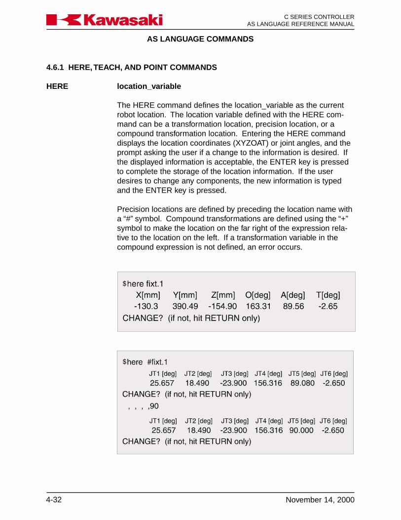
AS LANGUAGE COMMANDS
C SERIES CONTROLLERAS LANGUAGE REFERENCE MANUAL
4-32 November 14, 2000
Ka a aw s k
4.6.1 HERE, TEACH, AND POINT COMMANDS
HERE location_variable
The HERE command defines the location_variable as the currentrobot location. The location variable defined with the HERE com-mand can be a transformation location, precision location, or acompound transformation location. Entering the HERE commanddisplays the location coordinates (XYZOAT) or joint angles, and theprompt asking the user if a change to the information is desired. Ifthe displayed information is acceptable, the ENTER key is pressedto complete the storage of the location information. If the userdesires to change any components, the new information is typedand the ENTER key is pressed.
Precision locations are defined by preceding the location name witha “#” symbol. Compound transformations are defined using the “+”symbol to make the location on the far right of the expression rela-tive to the location on the left. If a transformation variable in thecompound expression is not defined, an error occurs.
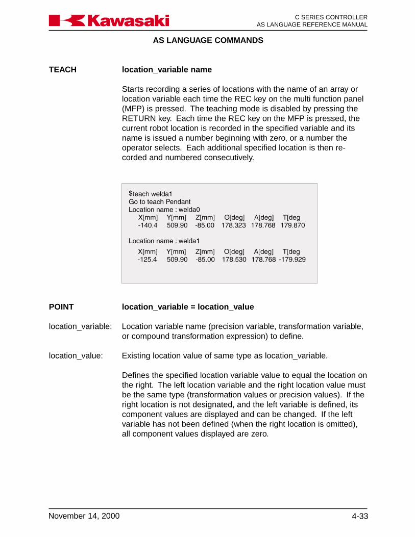
AS LANGUAGE COMMANDS
4-33November 14, 2000
Ka a aw s k C SERIES CONTROLLERAS LANGUAGE REFERENCE MANUAL
TEACH location_variable name
Starts recording a series of locations with the name of an array orlocation variable each time the REC key on the multi function panel(MFP) is pressed. The teaching mode is disabled by pressing theRETURN key. Each time the REC key on the MFP is pressed, thecurrent robot location is recorded in the specified variable and itsname is issued a number beginning with zero, or a number theoperator selects. Each additional specified location is then re-corded and numbered consecutively.
POINT location_variable = location_value
location_variable: Location variable name (precision variable, transformation variable,or compound transformation expression) to define.
location_value: Existing location value of same type as location_variable.
Defines the specified location variable value to equal the location onthe right. The left location variable and the right location value mustbe the same type (transformation values or precision values). If theright location is not designated, and the left variable is defined, itscomponent values are displayed and can be changed. If the leftvariable has not been defined (when the right location is omitted),all component values displayed are zero.
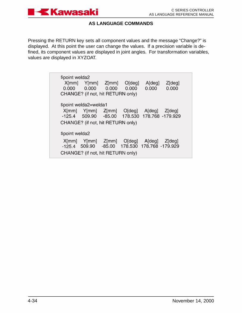
AS LANGUAGE COMMANDS
C SERIES CONTROLLERAS LANGUAGE REFERENCE MANUAL
4-34 November 14, 2000
Ka a aw s k
Pressing the RETURN key sets all component values and the message “Change?” isdisplayed. At this point the user can change the values. If a precision variable is de-fined, its component values are displayed in joint angles. For transformation variables,values are displayed in XYZOAT.

AS LANGUAGE COMMANDS
4-35November 14, 2000
Ka a aw s k C SERIES CONTROLLERAS LANGUAGE REFERENCE MANUAL
POINT/XPOINT/Y transformation_variable = transformation_valuePOINT/ZPOINT/OAT Sets the component (X, Y, Z, O, A, T or JT7) of the location on thePOINT/O left-hand side to be equal to the location variable on the right-handPOINT/A side.POINT/TPOINT/7
transformation_variable: Name of a transformation variable for which a value is set.
transformation_value: Transformation value from which the component value is obtained.

AS LANGUAGE COMMANDS
C SERIES CONTROLLERAS LANGUAGE REFERENCE MANUAL
4-36 November 14, 2000
Ka a aw s k
4.6.2 TOOL AND BASE COMMANDS
TOOL transformation_value
Defines the location and direction of the tool center point relative tothe tool mounting flange of the robot.
transformation_value: Transformation value must be a previously defined variable or a
compound transformation. If omitted, the current tool transforma-tion value is displayed for modification.
If NULL is designated for transformation_value, tool transformationvalue is set to “null tool”. “Null tool” has its center on the tool mount-ing flange surface, and has its coordinate axes parallel to the re-spective coordinate axes of the last joint of the robot. (“Null tool” isrepresented by the transformation value [0, 0, 0, 0, 0, 0]). At thesystem initialization, tool transformation value is set to the null toolautomatically.
After the tool transformation value is set, the values (XYZOAT) aredisplayed on the screen, and the message “change?” is displayed.To change component values, enter new values separated by com-mas and press the ENTER key.
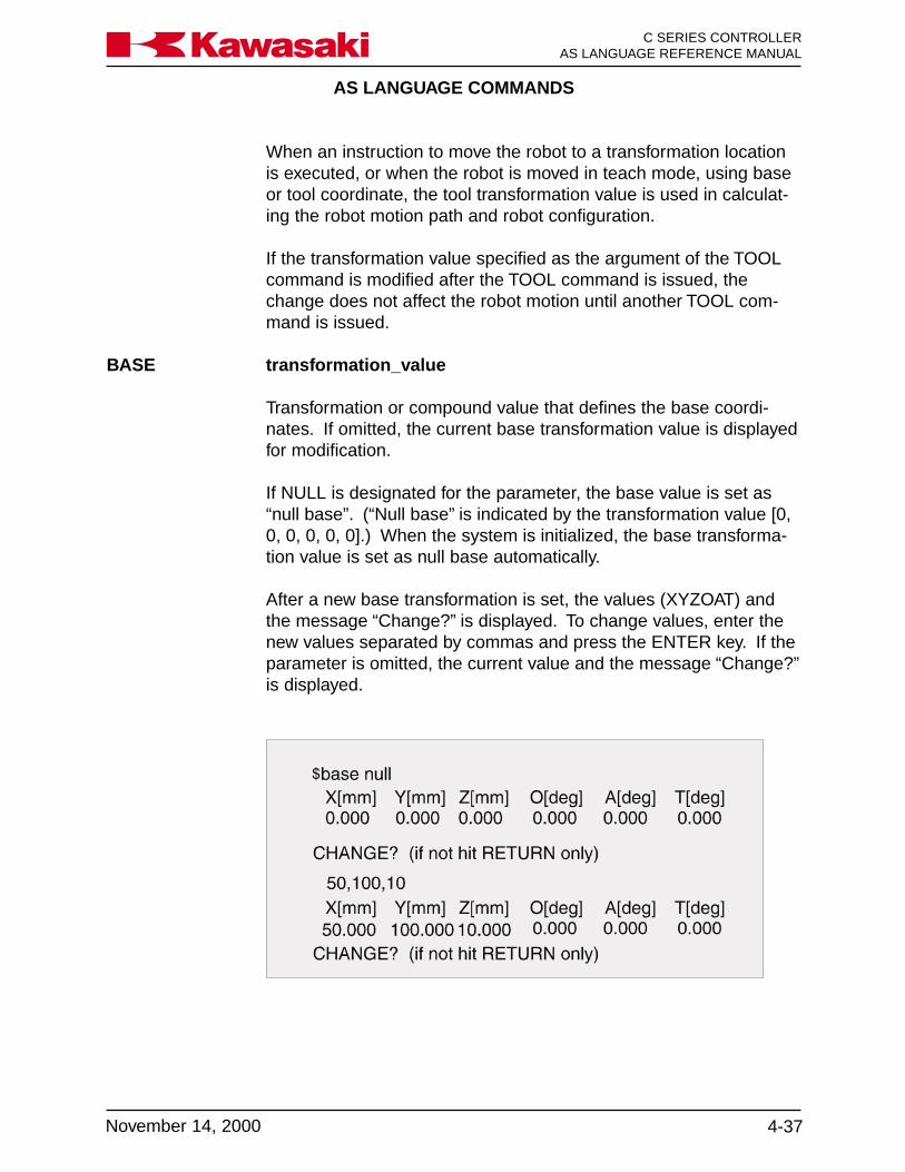
AS LANGUAGE COMMANDS
4-37November 14, 2000
Ka a aw s k C SERIES CONTROLLERAS LANGUAGE REFERENCE MANUAL
When an instruction to move the robot to a transformation locationis executed, or when the robot is moved in teach mode, using baseor tool coordinate, the tool transformation value is used in calculat-ing the robot motion path and robot configuration.
If the transformation value specified as the argument of the TOOLcommand is modified after the TOOL command is issued, thechange does not affect the robot motion until another TOOL com-mand is issued.
BASE transformation_value
Transformation or compound value that defines the base coordi-nates. If omitted, the current base transformation value is displayedfor modification.
If NULL is designated for the parameter, the base value is set as“null base”. (“Null base” is indicated by the transformation value [0,0, 0, 0, 0, 0].) When the system is initialized, the base transforma-tion value is set as null base automatically.
After a new base transformation is set, the values (XYZOAT) andthe message “Change?” is displayed. To change values, enter thenew values separated by commas and press the ENTER key. If theparameter is omitted, the current value and the message “Change?”is displayed.
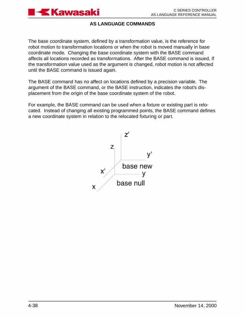
AS LANGUAGE COMMANDS
C SERIES CONTROLLERAS LANGUAGE REFERENCE MANUAL
4-38 November 14, 2000
Ka a aw s k
The base coordinate system, defined by a transformation value, is the reference forrobot motion to transformation locations or when the robot is moved manually in basecoordinate mode. Changing the base coordinate system with the BASE commandaffects all locations recorded as transformations. After the BASE command is issued, Ifthe transformation value used as the argument is changed, robot motion is not affecteduntil the BASE command is issued again.
The BASE command has no affect on locations defined by a precision variable. Theargument of the BASE command, or the BASE instruction, indicates the robot’s dis-placement from the origin of the base coordinate system of the robot.
For example, the BASE command can be used when a fixture or existing part is relo-cated. Instead of changing all existing programmed points, the BASE command definesa new coordinate system in relation to the relocated fixturing or part.
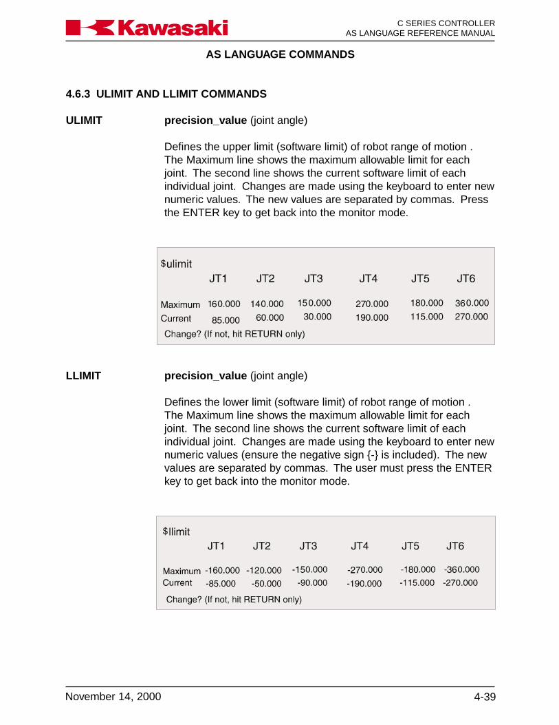
AS LANGUAGE COMMANDS
4-39November 14, 2000
Ka a aw s k C SERIES CONTROLLERAS LANGUAGE REFERENCE MANUAL
4.6.3 ULIMIT AND LLIMIT COMMANDS
ULIMIT precision_value (joint angle)
Defines the upper limit (software limit) of robot range of motion .The Maximum line shows the maximum allowable limit for eachjoint. The second line shows the current software limit of eachindividual joint. Changes are made using the keyboard to enter newnumeric values. The new values are separated by commas. Pressthe ENTER key to get back into the monitor mode.
LLIMIT precision_value (joint angle)
Defines the lower limit (software limit) of robot range of motion .The Maximum line shows the maximum allowable limit for eachjoint. The second line shows the current software limit of eachindividual joint. Changes are made using the keyboard to enter newnumeric values (ensure the negative sign {-} is included). The newvalues are separated by commas. The user must press the ENTERkey to get back into the monitor mode.

AS LANGUAGE COMMANDS
C SERIES CONTROLLERAS LANGUAGE REFERENCE MANUAL
4-40 November 14, 2000
Ka a aw s k
4.6.4 SETHOME COMMAND
SETHOME accuracy, HERESET2HOME accuracy, HERE
accuracy: The acceptable range of the HOME position (in millimeters). Ifomitted it is assumed to be one (1) millimeter. This range deter-mines when the dedicated outputs for the HOME positions turn on.
HERE: If the argument HERE is specified, the HOME position is changedto the current robot joint positions. If the argument HERE is omit-ted, the current HOME value is displayed. In either case, the query“Change?” appears. To change components, enter new valuesseparated by commas. Press the ENTER key to terminate thecommand.

AS LANGUAGE COMMANDS
4-41November 14, 2000
Ka a aw s k C SERIES CONTROLLERAS LANGUAGE REFERENCE MANUAL
4.6.5 WHERE COMMAND
WHERE display_mode
Displays the current robot location. If the display mode is omitted,the current location is displayed. When a display mode is specified,the current values are displayed continuously until the ENTER keyis pressed.
display_mode:
WHERE Displays the current robot location in both joint angles and basecoordinates (XYZOAT).
WHERE 1 Displays the current location in joint angles.
WHERE 2 Displays the current location in base coordinates (XYZOAT) (mm,deg).
WHERE 3 Displays the current instructed values (deg).
WHERE 4 Displays deviations from the instructed values (bit).
WHERE 5 Displays encoder value of each joint (bit).
WHERE 6 Displays speed of each joint (deg/sec).
The display on the next page (Figure 4-2) depicts the terminalscreen when the WHERE command is issued. WHERE1 throughWHERE6 have a continuously scrolling screen and display thecurrent information.

AS LANGUAGE COMMANDS
C SERIES CONTROLLERAS LANGUAGE REFERENCE MANUAL
4-42 November 14, 2000
Ka a aw s k
Figure 4-2 Where Command Display Screen

AS LANGUAGE COMMANDS
4-43November 14, 2000
Ka a aw s k C SERIES CONTROLLERAS LANGUAGE REFERENCE MANUAL
4.7 SYSTEM INFORMATION
ERRLOG Displays a history of error conditions.OPLOG Displays a history of operations performed by the operator.STATUS Displays status information.FREE Displays amount of free memory.ID Displays robot model information and software versionHELP Displays AS Language commands available to the operator
4.7.1 ERRLOG AND OPLOG COMMANDS
ERRLOG The ERRLOG command displays a history of error conditions thatare stored in system memory. A history of the last one thousanderrors is retained. The display unit displays ten errors at a timestarting from the most recent to the oldest. The user can alternatebetween the next screen and the previous screen by using functionkeys F4 and F5. The format of the error log is shown below:
date time error code error message12-01 15:40 (-203) xxxxxxxxxxxxxxxxxxxxxxx12-01 15:23 (-600) xxxxxxxxxxxxxxxxxxxxxxx
To see additional ERRLOG or OPLOG errors, press the space baror the F5 function key. To terminate the command, press the EN-TER key, or the EXIT key on the keyboard.
OPLOG The OPLOG command displays a history of the last one hundredoperations performed by the operator, and any messages related tooperations. Like the ERRLOG command, ten operations or mes-sages are displayed from the most recent to the oldest. To see theremaining operations, press the space bar or the F5 function key.To terminate the command, press the ENTER key, or the EXIT keyon the keyboard. The format of the oplog is shown below:
date time operation message12-01 15:54 where12-01 15:40 ED DEMO12-01 15:00 System Data Home-1 Set
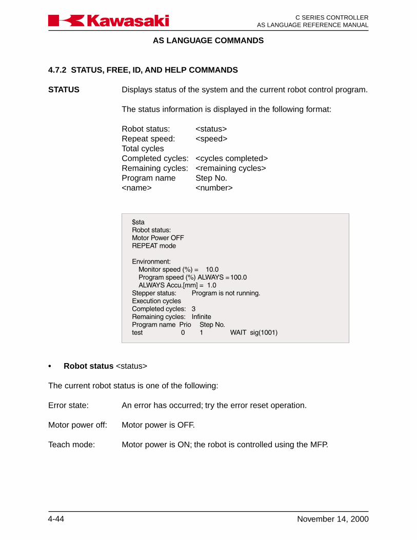
AS LANGUAGE COMMANDS
C SERIES CONTROLLERAS LANGUAGE REFERENCE MANUAL
4-44 November 14, 2000
Ka a aw s k
• Robot status <status>
The current robot status is one of the following:
Error state: An error has occurred; try the error reset operation.
Motor power off: Motor power is OFF.
Teach mode: Motor power is ON; the robot is controlled using the MFP.
4.7.2 STATUS, FREE, ID, AND HELP COMMANDS
STATUS Displays status of the system and the current robot control program.
The status information is displayed in the following format:
Robot status: <status>Repeat speed: <speed>Total cyclesCompleted cycles: <cycles completed>Remaining cycles: <remaining cycles>Program name Step No.<name> <number>

AS LANGUAGE COMMANDS
4-45November 14, 2000
Ka a aw s k C SERIES CONTROLLERAS LANGUAGE REFERENCE MANUAL
FREE Displays the size of memory area not currently used, both in per-centages and in bytes.
ID Displays robot identification and software version information.
Check mode: Motor power is ON; the robot is in the check mode.
Repeat mode: Motor power is ON; the robot is controlled by the robot controlprogram.
Program running: Motor power is ON; the robot control program is running.
Program waiting: Motor power is ON; the robot control program is running and in await condition (executing a WAIT, SWAIT, or TWAIT instruction).
• Repeat speed <speed>The current monitor speed (in percentages).
• Completed cycles <cycles completed>Execution cycles already completed.
• Remaining cycles <remaining cycles>Remaining execution cycles. If a “-1” execution cycle was specified in the EX-ECUTE command, “infinite” is displayed.
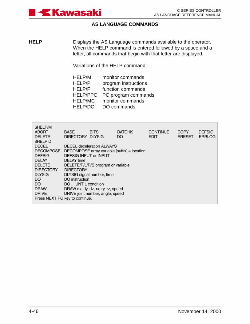
AS LANGUAGE COMMANDS
C SERIES CONTROLLERAS LANGUAGE REFERENCE MANUAL
4-46 November 14, 2000
Ka a aw s k
HELP Displays the AS Language commands available to the operator.When the HELP command is entered followed by a space and aletter, all commands that begin with that letter are displayed.
Variations of the HELP command:
HELP/M monitor commandsHELP/P program instructionsHELP/F function commandsHELP/PPC PC program commandsHELP/MC monitor commandsHELP/DO DO commands
AS LANGUAGE COMMANDS
4-47November 14, 2000
Ka a aw s k C SERIES CONTROLLERAS LANGUAGE REFERENCE MANUAL
4.8 SYSTEM CONTROL
SYSINIT Initializes the entire system.TIME Sets the date and time.ERESET Resets the error condition.SWITCH Displays the system switch settings.ON Enables the system switches.OFF Disables the system switches.HSETCLAMP Sets the default clamp specifications.ZSIGSPEC Sets and displays the total number of I/O signals.ZZERO Displays or sets the zeroing data.BATCHK Enables/disables battery low voltage check.ENCCHK_EMG Sets the range to check position variance after an E-stop, when
power is reapplied.ENCCHK_PON Sets the range of encoder deviation, for error display.SLOW_REPEAT Sets slow repeat mode speed.REC_ACCEPT Enables/disables recording and or changing programs.ENV_DATA Sets auto servo off timer and teach pendant connect/disconnect.ENV2_DATA Sets multi functon panel and terminal connect/disconnect.CHSUM Clears check sum error.
4.8.1 SYSINIT, TIME, AND ERESET COMMANDS
SYSINIT The system is initialized, and all programs, location variables, realvariables and character string variables are erased. All systemparameters under the DATA SET key (speed, accuracy, timers,system switches, etc.) are reset to default conditions. TheERRLOG and OPLOG data are not affected by this command.
TIME date_and_time
Sets the date and time. The format is yy-dd-mm and hh:mm:ss.
If the date and time are set by this command, the internal systemvariable used to set the present time is changed.
The respective element value allowed is as follows:
yy year (00-99)dd day (01-31)mm month (01-12)hh hours (00-23)mm min. (00-59)ss sec. (00-59)

AS LANGUAGE COMMANDS
C SERIES CONTROLLERAS LANGUAGE REFERENCE MANUAL
4-48 November 14, 2000
Ka a aw s k
If the parameters are omitted, the present time is displayed and thesystem awaits a change. To make a change, enter the present timeor date in the format described above. To terminate the command,press the ENTER key.
ERESET Resets the current error condition (the same function as the ER-ROR RESET button on the control panel). The ERESET commandis ineffective when an error occurs continuously.
4.8.2 SWITCH, HSETCLAMP, AND ZSIGSPEC COMMANDS
SWITCH switch_name,...ONswitch_name,...OFF
Displays (or changes) system switch settings.
switch_name: Name of a system switch to display or change. If omitted, all switchsettings are displayed.
ON or OFF If the argument ON is specified, the switches are enabled; if OFF isspecified, switches are disabled. If omitted, the switch status isdisplayed without changing.
HSETCLAMP Assigns signal numbers to operate material handling clamps.
Additional clamp data is set in auxiliary function 114.

AS LANGUAGE COMMANDS
4-49November 14, 2000
Ka a aw s k C SERIES CONTROLLERAS LANGUAGE REFERENCE MANUAL
ZSIGSPEC This command sets and displays the default setting for the totalnumber of input and output signals installed in the controller.
To use this command, type in ZSIGSPEC at the system prompt,and press the ENTER key. Type in the number of I/O signals, andpress the ENTER key.
To display the current settings, type the ZSIGSPEC command, andpress the ENTER key. To exit the ZSIGSPEC command withoutchanging the data press the ENTER key again.
4.8.3 ZZERO COMMAND
ZZERO joint_number
The ZZERO command is used to set the encoder rotation count andto display or set the robot’s zeroing data. The encoder rotationcount is stored in the encoder and indicates the encoder revolutioncount from the zero position. The zeroing data is an absolute en-coder value stored in memory that coincides with the mechanicalzero position of each joint.
joint_number: When the ZZERO command is used to view or set the robot’s zero-ing data, the joint number specifies a specific joint. Entering a 0indicates the zeroing data for all joints is set, while 1 through 7indicate the zeroing data for the individual joint is set.

AS LANGUAGE COMMANDS
C SERIES CONTROLLERAS LANGUAGE REFERENCE MANUAL
4-50 November 14, 2000
Ka a aw s k
The first step in the zeroing process is to jog the robot to the position where the scribemarks, for the joint(s) to zero, are aligned. If the robot does not move because thecurrent position is recognized as out of range, the robot is zeroed where it is, to allowjogging operations, and then rezeroed when the scribe marks are aligned. The nextstep in the zeroing process is to set the current encoder count offset to a 0° midpointreference, this is done with the ZZERO 10_ command. Two examples of the ZZERO10_ command, ZZERO 100 for all joints, and ZZERO 102 for joint 2 are shown below.
NOTE
The robot axes can be zeroed individually but may re-quire other axes to be positioned at zero. Refer to the CSeries Controller Electrical Maintenance Manual, unit 8,Zeroing, for axes that must be positioned simulta-neously before zeroing.
After the encoder rotation counter is reset, the ZZERO _ command is used to set thejoint(s) to 0°. An example of the ZZERO _ command, ZZERO 0 for all joints is shownbelow.
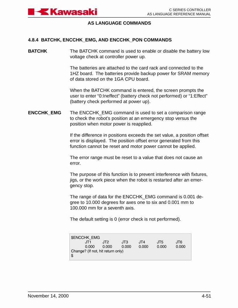
AS LANGUAGE COMMANDS
4-51November 14, 2000
Ka a aw s k C SERIES CONTROLLERAS LANGUAGE REFERENCE MANUAL
4.8.4 BATCHK, ENCCHK_EMG, AND ENCCHK_PON COMMANDS
BATCHK The BATCHK command is used to enable or disable the battery lowvoltage check at controller power up.
The batteries are attached to the card rack and connected to the1HZ board. The batteries provide backup power for SRAM memoryof data stored on the 1GA CPU board.
When the BATCHK command is entered, the screen prompts theuser to enter “0:Ineffect” (battery check not performed) or “1:Effect”(battery check performed at power up).
ENCCHK_EMG The ENCCHK_EMG command is used to set a comparison rangeto check the robot’s position at an emergency stop versus theposition when motor power is reapplied.
If the difference in positions exceeds the set value, a position offseterror is displayed. The position offset error generated from thisfunction cannot be reset and motor power cannot be applied.
The error range must be reset to a value that does not cause anerror.
The purpose of this function is to prevent interference with fixtures,jigs, or the work piece when the robot is restarted after an emer-gency stop.
The range of data for the ENCCHK_EMG command is 0.001 de-gree to 10.000 degrees for axes one to six and 0.001 mm to100.000 mm for a seventh axis.
The default setting is 0 (error check is not performed).

AS LANGUAGE COMMANDS
C SERIES CONTROLLERAS LANGUAGE REFERENCE MANUAL
4-52 November 14, 2000
Ka a aw s k
ENCCHK_PON The ENCCHK_PON command is used to set the range of encoderdeviation allowed before an error is displayed at controller power up.
The encoder value at controller power down is compared to theencoder value at controller power up. If the difference is larger thanthe range set, a JT encoder abnormality error is displayed.
The range of data is from 0.001 degree to 10.000 degrees for axesone to six and from 0.001 mm to 100.000 mm for a seventh axis.
The default setting 2.0 degrees.
If the setting is too low, error messages may be displayed when thesystem is performing within design performance specifications.
4.8.5 SLOW_REPEAT, REC_ACCEPT, ENV_DATA, AND ENV2_DATA COMMANDS
SLOW_REPEAT The SOLW_REPEAT command is used to set the SLOW_REPEATmode speed of the robot from 1 to 25% of maximum speed.
A dedicated input signal must be assigned for the SLOW_REPEATmode function.
When this signal is ON, the robot operates at the speed set with theSLOW_REPEAT command.
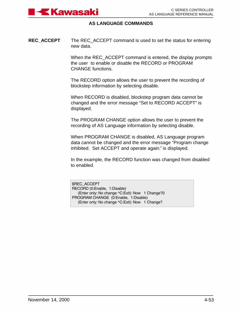
AS LANGUAGE COMMANDS
4-53November 14, 2000
Ka a aw s k C SERIES CONTROLLERAS LANGUAGE REFERENCE MANUAL
REC_ACCEPT The REC_ACCEPT command is used to set the status for enteringnew data.
When the REC_ACCEPT command is entered, the display promptsthe user to enable or disable the RECORD or PROGRAMCHANGE functions.
The RECORD option allows the user to prevent the recording ofblockstep information by selecting disable.
When RECORD is disabled, blockstep program data cannot bechanged and the error message “Set to RECORD ACCEPT” isdisplayed.
The PROGRAM CHANGE option allows the user to prevent therecording of AS Language information by selecting disable.
When PROGRAM CHANGE is disabled, AS Language programdata cannot be changed and the error message “Program changeinhibited. Set ACCEPT and operate again.” is displayed.
In the example, the RECORD function was changed from disabledto enabled.

AS LANGUAGE COMMANDS
C SERIES CONTROLLERAS LANGUAGE REFERENCE MANUAL
4-54 November 14, 2000
Ka a aw s k
ENV_DATA The ENV_DATA command is used to set the auto servo timer andidentify if a teach pendant is installed.
When the ENV_DATA command is entered, the display prompts theuser to set information for the AUTO SERVO OFF TIMER andTEACH PENDANT.
The AUTO SERVO OFF TIMER sets a time period that motor powerremains ON if no movement of the robot has occurred. The autoservo timer function is designed to save energy by using the brakesto maintain robot position.
If the AUTO SERVO OFF TIMER is not used electrical power andservo motors maintain robot position.
When the robot has not moved and the auto servo timer reaches itsset value, the brakes are applied and servo motor power is re-moved.
The motor power light remains ON and the robot begins motionunder the same conditions as if the auto servo timer did not removepower from the motors.
The ENV_DATA command is used to identify if a TEACH PENDANTis connected.
The deadman buttons and the emergency stop button are hard-wired and a jumper (or a different user interface) must be installed ifthe teach pendant is disconnected.
In the example, the AUTO SERVO OFF TIMER is set to 600 sec-onds and a TEACH PENDANT is installed.
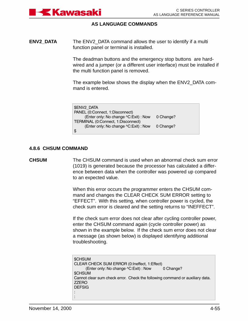
AS LANGUAGE COMMANDS
4-55November 14, 2000
Ka a aw s k C SERIES CONTROLLERAS LANGUAGE REFERENCE MANUAL
ENV2_DATA The ENV2_DATA command allows the user to identify if a multifunction panel or terminal is installed.
The deadman buttons and the emergency stop buttons are hard-wired and a jumper (or a different user interface) must be installed ifthe multi function panel is removed.
The example below shows the display when the ENV2_DATA com-mand is entered.
4.8.6 CHSUM COMMAND
CHSUM The CHSUM command is used when an abnormal check sum error(1019) is generated because the processor has calculated a differ-ence between data when the controller was powered up comparedto an expected value.
When this error occurs the programmer enters the CHSUM com-mand and changes the CLEAR CHECK SUM ERROR setting to“EFFECT”. With this setting, when controller power is cycled, thecheck sum error is cleared and the setting returns to “INEFFECT”.
If the check sum error does not clear after cycling controller power,enter the CHSUM command again (cycle controller power) asshown in the example below. If the check sum error does not cleara message (as shown below) is displayed identifying additionaltroubleshooting.

AS LANGUAGE COMMANDS
C SERIES CONTROLLERAS LANGUAGE REFERENCE MANUAL
4-56 November 14, 2000
Ka a aw s k
4.9 SIGNAL COMMANDS
SIGNAL Turns ON (or OFF) signals.PULSE Turns ON a signal during the specified period of time.DYLSIG Turns ON a signal after the specified time has elapsed.BITS Sets a group of signals to be equal to the specified value.IO Displays I/O signal status.RESET Resets all external output signals.DEFSIG Sets or cancels signals for particular uses.
4.9.1 SIGNAL, PULSE, DLYSIG, AND BITS COMMANDS
SIGNAL signal_number
Sets external output signals or internal status signals to ON/OFF.Represents the number of an external output signal or an internalstatus signal. If this value is positive, the signal is turned ON; ifnegative, the signal is turned OFF.
signal_number: The signal number designates whether the signal is an externaloutput or internal status signal. For external output signals, thestandard number is from 1 to 32. Additional hardware is installed toincrease the number to a maximum of 256. Internal status signalnumbers range from 2001 to 2256. Input signals cannot be desig-nated.
If the signal number is positive, the signal is turned ON; if negative,the signal is turned OFF. If “0” is given, no output signals arechanged.
Multiple signal numbers are separated with comas, as shown in theexample below.
Example: SIG 4,5,-8,-10 turns outputs 4 and 5 ON and outputs 8 and 10 OFF.
AS LANGUAGE COMMANDS
4-57November 14, 2000
Ka a aw s k C SERIES CONTROLLERAS LANGUAGE REFERENCE MANUAL
PULSE signal_number, time (seconds)
Turns ON the specified signal (external output or internal status) forthe given period of time only.
signal_number: Represents the number of the signal to turn on for the specifiedtime. Numbers greater than 32, or negative numbers cannot bedesignated (0-32).
time: The period of time the signal is kept ON (in seconds). If omitted,0.2 seconds is assumed.
Example: PULSE 4,3.56 turns output 4 ON for 3.56 seconds.
DLYSIG signal_number, time (seconds)
Turns the specified signal ON or OFF after a given time haselapsed.
signal_number: Represents the number of an external output signal or an internalstatus signal. If this value is positive, the signal is tuned ON; and ifnegative, the signal is turned OFF. Acceptable signal numbers arefrom 1 to 32, and from 2001 to 2032.
time: Time period after which the signal is turned ON or OFF (in sec-onds).
Example: DLYSIG 2,4.5 turns output 2 ON after 4.5 seconds has elapsed,where as DLYSIG -2,4.5 turns output 2 OFF after 4.5 seconds haselapsed.
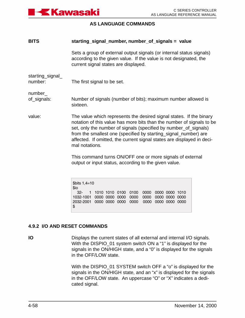
AS LANGUAGE COMMANDS
C SERIES CONTROLLERAS LANGUAGE REFERENCE MANUAL
4-58 November 14, 2000
Ka a aw s k
BITS starting_signal_number, number_of_signals = value
Sets a group of external output signals (or internal status signals)according to the given value. If the value is not designated, thecurrent signal states are displayed.
starting_signal_number: The first signal to be set.
number_of_signals: Number of signals (number of bits); maximum number allowed is
sixteen.
value: The value which represents the desired signal states. If the binarynotation of this value has more bits than the number of signals to beset, only the number of signals (specified by number_of_signals)from the smallest one (specified by starting_signal_number) areaffected. If omitted, the current signal states are displayed in deci-mal notations.
This command turns ON/OFF one or more signals of externaloutput or input status, according to the given value.
4.9.2 I/O AND RESET COMMANDS
IO Displays the current states of all external and internal I/O signals.With the DISPIO_01 system switch ON a “1” is displayed for thesignals in the ON/HIGH state, and a “0” is displayed for the signalsin the OFF/LOW state.
With the DISPIO_01 SYSTEM switch OFF a “o” is displayed for thesignals in the ON/HIGH state, and an “x” is displayed for the signalsin the OFF/LOW state. An uppercase “O” or “X” indicates a dedi-cated signal.

AS LANGUAGE COMMANDS
4-59November 14, 2000
Ka a aw s k C SERIES CONTROLLERAS LANGUAGE REFERENCE MANUAL
The signal numbers are displayed from right to left. The signalstates are continuously updated until the RETURN key is pressed.
When IO or IO 1 is entered, the states of signals 1-32, 1001-1032,and 2001-2032 are displayed as shown below.
When IO 2 is entered, the states of signals 33-64, 1033-1064, and2033-2064 are displayed as shown below.
When IO 3 or IO 4 is entered, the states of signals 65-96, 1065-1096, 2065-2096 or 97-128, 1097-1128, 2097-2128 are displayed.
If a controller is not configured for a range of signals a “-” is dis-played for the signal number state as shown below.
RESET Resets all external output signals to OFF. This command has noaffect on dedicated signals.

AS LANGUAGE COMMANDS
C SERIES CONTROLLERAS LANGUAGE REFERENCE MANUAL
4-60 November 14, 2000
Ka a aw s k
4.9.3 DEFSIG COMMAND
DEFSIG Input/Output
The DEFSIG command is used to display or set dedicated signals.The DEFSIG command without an argument displays a list of dedi-cated signals, conditions and signal numbers as shown below. Thedisplay mode does not allow the state of the signals, or the signalnumbers, to be changed.
When input or output is specified, the dedicated input or outputsignals are displayed. The state of the signals, set or cancel andthe signal numbers can be changed in this mode. To exit this modetype “e” for EXIT and press enter.
The DEFSIG OUTPUT display is shown below.
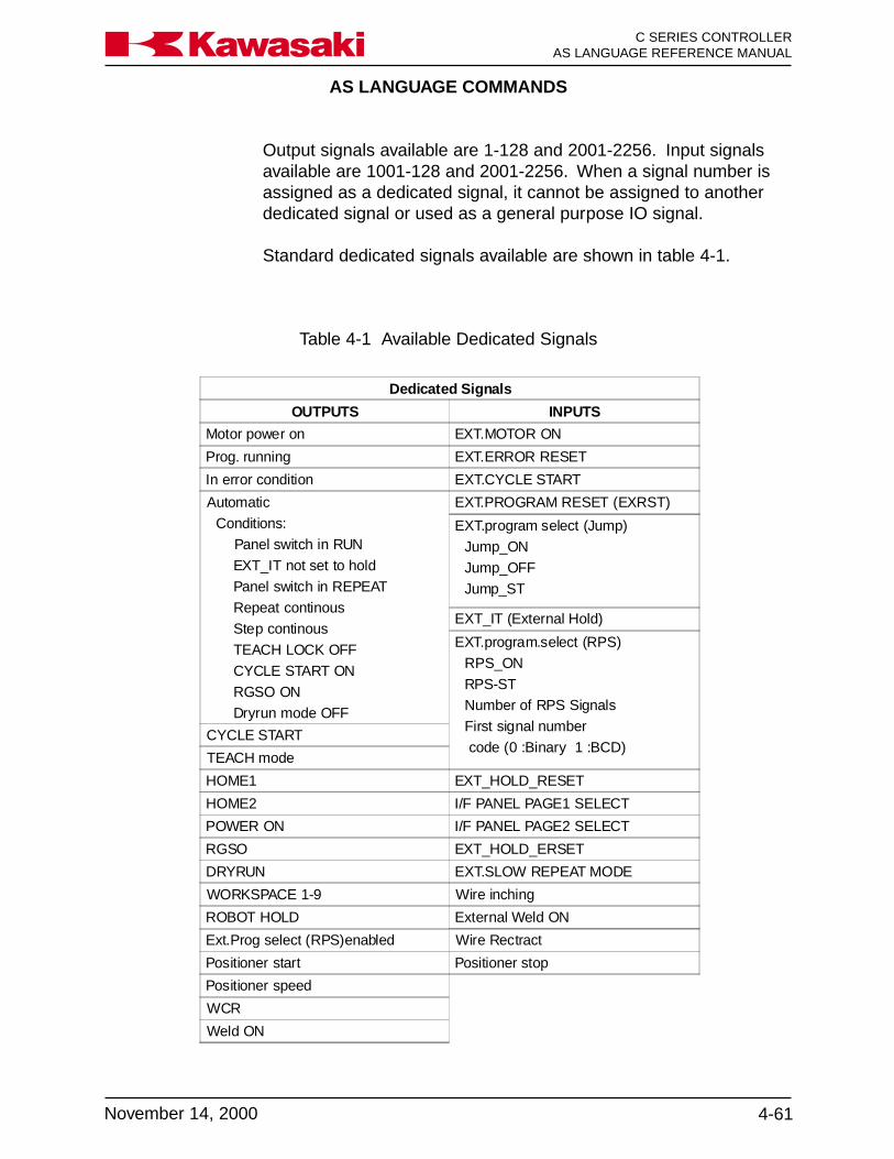
AS LANGUAGE COMMANDS
4-61November 14, 2000
Ka a aw s k C SERIES CONTROLLERAS LANGUAGE REFERENCE MANUAL
Dedicated Signals
OUTPUTS INPUTS
Motor power on EXT.MOTOR ON
Prog. running EXT.ERROR RESET
In error condition EXT.CYCLE START
Automatic
Conditions:
Panel switch in RUN
EXT_IT not set to hold
Panel switch in REPEAT
Repeat continous
Step continous
TEACH LOCK OFF
CYCLE START ON
RGSO ON
Dryrun mode OFF
EXT.PROGRAM RESET (EXRST)
EXT.program select (Jump)
Jump_ON
Jump_OFF
Jump_ST
EXT_IT (External Hold)
EXT.program.select (RPS)
RPS_ON
RPS-ST Number of RPS Signals
First signal number
code (0 :Binary 1 :BCD)CYCLE START
TEACH mode
HOME1 EXT_HOLD_RESET
HOME2 I/F PANEL PAGE1 SELECT
POWER ON I/F PANEL PAGE2 SELECT
RGSO EXT_HOLD_ERSET
DRYRUN EXT.SLOW REPEAT MODE
WORKSPACE 1-9 Wire inching
ROBOT HOLD External Weld ON
Ext.Prog select (RPS)enabled Wire Rectract
Positioner start Positioner stop
Positioner speed
WCR
Weld ON
Table 4-1 Available Dedicated Signals
Output signals available are 1-128 and 2001-2256. Input signalsavailable are 1001-128 and 2001-2256. When a signal number isassigned as a dedicated signal, it cannot be assigned to anotherdedicated signal or used as a general purpose IO signal.
Standard dedicated signals available are shown in table 4-1.
AS LANGUAGE COMMANDS
C SERIES CONTROLLERAS LANGUAGE REFERENCE MANUAL
4-62 November 14, 2000
Ka a aw s k
4.10 Z-SERIES ROBOTS AS LANGUAGE COMMANDS
For more information on the Z-series robot functions, refer to the C Series ControllerOperations and Programming Manual.
4.10.1 1GV ARM ID BOARD FUNCTIONS AND COMMANDS
The arm ID board is installed in the robot arm ID board box. Thearm ID board stores model information, maintenance log informa-tion, and I/O signal settings. Functions and settings of the arm IDboard are accessed from the controller.
The functions and settings of the arm ID board include:
• entries to the maintenance log• display of the maintenance log• deletion of maintenance log entries• Settings of I/O signals to the robot arm
The AS Language commands used with the arm ID board are:
• MNTREC – maintenance log record• MNTLOG – maintenance log display• ARMIOSET – arm ID board I/O set
$MNTREC robot_number
The MNTREC command is used to register maintenance log en-tries. If the robot number is omitted 1 is assumed. The mainte-nance log stores the last 100 entries. When over 100 entries aremade the oldest entry is deleted.
Example:$MNTREC <ENTER>Person in charge of record (input)? Joe Supervisor <ENTER>
Non of abnormality : 0 Memo input : 1? 1<ENTER>(Memo input) : JT1 motor replaced <ENTER>
content of registration
Person in charge : Joe SupervisorMemo : JT1 motor replaced

AS LANGUAGE COMMANDS
4-63November 14, 2000
Ka a aw s k C SERIES CONTROLLERAS LANGUAGE REFERENCE MANUAL
Do not turn controller power off until “Writing ended” isdisplayed, or entry is not accepted.
NOTE
Are you sure? (Yes:1, No:0) 1 <ENTER>arm ID board is busy.Writing ended.$

AS LANGUAGE COMMANDS
C SERIES CONTROLLERAS LANGUAGE REFERENCE MANUAL
4-64 November 14, 2000
Ka a aw s k
$MTLOG robot_number
The MNTLOG command is used to display the contents of themaintenance log. If the robot number is omitted 1 is assumed. Themaintenance log displays the last 100 entries, starting with the mostrecent. Press ENTER to stop the listing.
Example:$MNTLOG <ENTER>1-[00/06/24 12:03:00 Joe Supervisor][REPLACE JT1 HARNESS]2-[00/04/12 14:20:32 Kawasaki][REPLACE JT2 MOTOR]
$ARMIOSET robot_number,output_signal_No.,number_of_output_signals,input_signal_No.,number_of_input_signals
The ARMIOSET command is used to allocate arm board parallel I/O signals. If the robot number is omitted 1 is assumed. Top signalrange for output is 1 - 64. Number of output signals is 1 - 8. Topsignal range for input is 1001 - 1064. Number of input signals is 1 -24.
Example:$ARMIOSET <ENTER>
TOP SIGNAL, SIGNAL NUMBEROUTPUT SIGNAL 1 0Change? (If not, Press RETURN only.)6,8 <ENTER>
TOP SIGNAL, SIGNAL NUMBEROUTPUT SIGNAL 6 8Change? (If not, Press RETURN only.)<ENTER>
TOP SIGNAL, SIGNAL NUMBERINPUT SIGNAL 1001 0Change? (If not, Press RETURN only.)1012,24 <ENTER>
TOP SIGNAL, SIGNAL NUMBERINPUT SIGNAL 1012 24Change? (If not, Press RETURN only.)<ENTER>
$

AS LANGUAGE COMMANDS
4-65November 14, 2000
Ka a aw s k C SERIES CONTROLLERAS LANGUAGE REFERENCE MANUAL
4.10.2 FAILURE PREDICTION FUNCTION, AUX 124 (OPTION)
This function establishes average current levels of motors during normal program opera-tion and monitors motor current.
Reduction gear failure is gradual and motor current increases in small increments as thereduction gear approaches failure.
If the current levels exceed the established normal level, a warning message is dis-played and an alarm signal is pulsed for one second.
If a program has varying operating conditions, such as payloads of different weights,that affect motor current this function can not be used.
Program teaching and verification must be completed before using this function. Ifchanges are made to the program average current levels must be revised.
4.10.2.1 FAILURE PREDICTION FUNCTION SETUP PROCEDURE
The AS Language command I2PG is used in programs to monitor motor torque (cur-rent). Each program must use the I2PG START pg (pg = program number) command atthe point in the program current monitoring begins. The I2PG END command is used toend current monitoring. For usage of the I2PG command see the example below.
AS LANGUAGE COMMANDS
C SERIES CONTROLLERAS LANGUAGE REFERENCE MANUAL
4-66 November 14, 2000
Ka a aw s k
4.10.3 COLLISION DETECTION FUNCTION
The collision detection function is used to minimize damage to tooling and robotic equip-ment.
To activate the collision detection function, several parameters are set, using functionscreens or AS Language commands. Settings using function screens are covered in theC Series Controller Operations and Programming Manual. Settings using AS Languagecommands are covered in the following sections.
4.10.3.1 SETTING TOOL WEIGHT DATA USING AS LANGUAGE WEIGHTCOMMAND
WEIGHT mass,center of gravity X Y and Z,inertia moment around X Y and Z
The mass (weight), center of gravity location, and the inertia moment of the tool (Figure4-3) are registered with the AS Language WEIGHT command. The arguments followthe command separated by comas (tool data is entered from the tool specification sheetor is available from the tool manufacturer).
The range of values are:
• load mass: 0 - load mass - kg• center of gravity location: -9999.9 - 10000.0 - mm• inertia moment: 0 - 999.99 - kg m2
Example:WEIGHT 10, 0, 74.4, 4.5, 5.1, .21, .52

AS LANGUAGE COMMANDS
4-67November 14, 2000
Ka a aw s k C SERIES CONTROLLERAS LANGUAGE REFERENCE MANUAL
4.10.3.2 RANGE OF THRESHOLD
The two types of thresholds are collision detection and shock detection.
Each threshold is set for motion in teach mode and in repeat mode.
These thresholds are set using AUX 148 on the multifunction panel, AS Languagemonitor commands and program instructions (Table 4-2), or by automatic calibrationusing Aux 148-3.
Figure 4-3 Tool Data
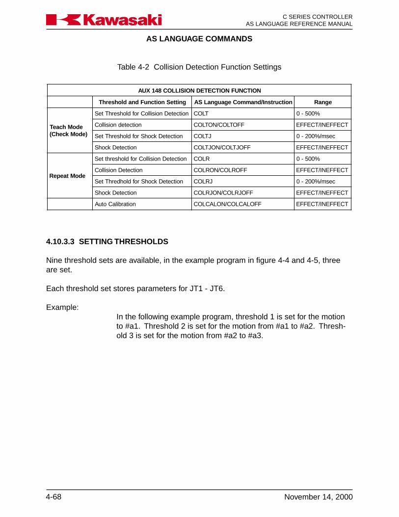
AS LANGUAGE COMMANDS
C SERIES CONTROLLERAS LANGUAGE REFERENCE MANUAL
4-68 November 14, 2000
Ka a aw s k
4.10.3.3 SETTING THRESHOLDS
Nine threshold sets are available, in the example program in figure 4-4 and 4-5, threeare set.
Each threshold set stores parameters for JT1 - JT6.
Example:In the following example program, threshold 1 is set for the motionto #a1. Threshold 2 is set for the motion from #a1 to #a2. Thresh-old 3 is set for the motion from #a2 to #a3.
Table 4-2 Collision Detection Function Settings
NOITCNUFNOITCETEDNOISILLOC841XUA
gnitteSnoitcnuFdnadlohserhT noitcurtsnI/dnammoCegaugnaLSA egnaR
edoMhcaeT)edoMkcehC(
noitceteDnoisilloCrofdlohserhTteS TLOC %005-0
noitcetednoisilloC FFOTLOC/NOTLOC TCEFFENI/TCEFFE
noitceteDkcohSrofdlohserhTteS JTLOC cesm/%002-0
noitceteDkcohS FFOJTLOC/NOJTLOC TCEFFENI/TCEFFE
edoMtaepeR
noitceteDnoisilloCrofdlohserhtteS RLOC %005-0
noitceteDnoisilloC FFORLOC/NORLOC TCEFFENI/TCEFFE
noitceteDkcohSrofdlohderhTteS JRLOC cesm/%002-0
noitceteDkcohS FFOJRLOC/NOJRLOC TCEFFENI/TCEFFE
noitarbilaCotuA FFOLACLOC/NOLACLOC TCEFFENI/TCEFFE

AS LANGUAGE COMMANDS
4-69November 14, 2000
Ka a aw s k C SERIES CONTROLLERAS LANGUAGE REFERENCE MANUAL
Figure 4-4 Collision Detection Sample Program
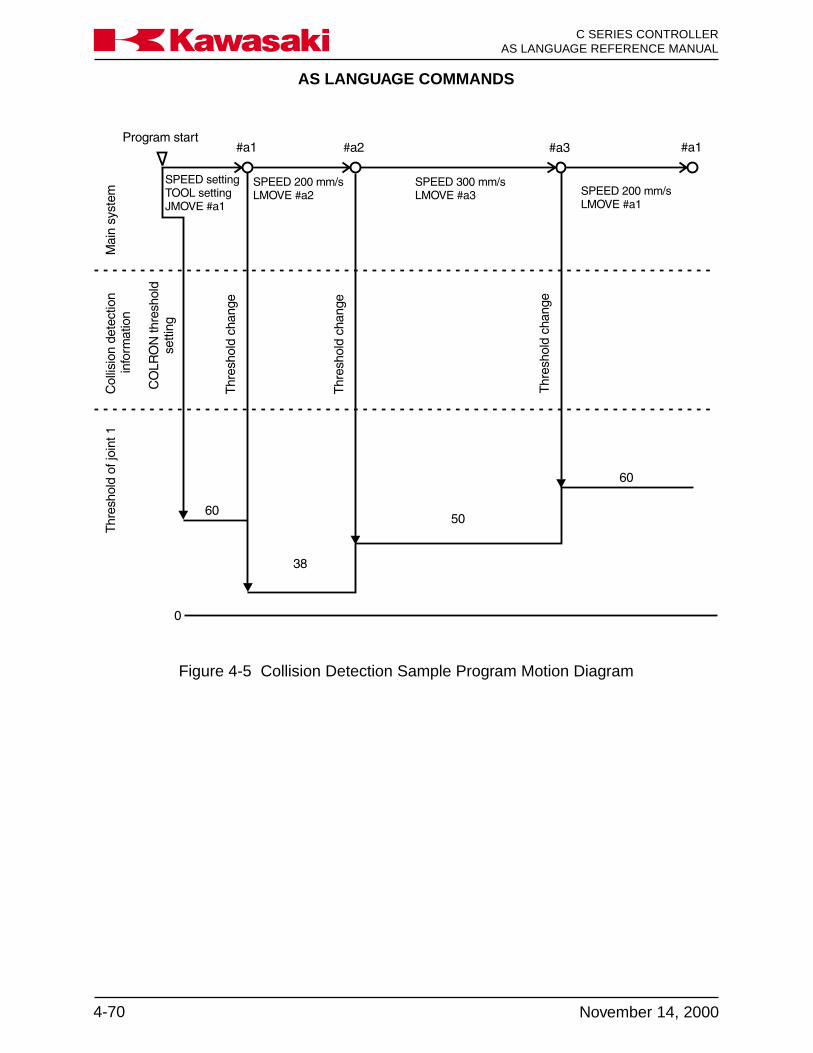
AS LANGUAGE COMMANDS
C SERIES CONTROLLERAS LANGUAGE REFERENCE MANUAL
4-70 November 14, 2000
Ka a aw s k
Figure 4-5 Collision Detection Sample Program Motion Diagram

AS LANGUAGE COMMANDS
4-71November 14, 2000
Ka a aw s k C SERIES CONTROLLERAS LANGUAGE REFERENCE MANUAL
To obtain an accurate threshold setting tool registration data must be accurate.
To obtain threshold 1 delete the current threshold data in the collision_detect program.Enter the CALCONON monitor command. Run the program collision_detect severaltimes, as it is normally run, with any peripherals and/or the work piece in place.
End the threshold setting with the CALCONOFF monitor command. Read the repeatmode threshold values using the COLR monitor command and enter the values in thecollision_detect program.
In the example program threshold 1 is effective for the entire program, unless changedfor steps using the COLR and the COLRJ commands. Threshold 2 is effective duringmovement from #a1 to #a2 or from #a2 to #a1. Threshold 3 is effective during move-ment from #a2 to #a3.
To obtain threshold 1: execute the program collision_detect.
To obtain threshold 2: execute the following program calib1.
Example:.PROGRAM calib1()WEIGHT 10,100,40,40,1,1.4,.52SPEED 200 mm/s ALWAYSJMOVE #a1
10LMOVE #a2DELAY 1LMOVE #a1DELAY 1GOTO 10.END
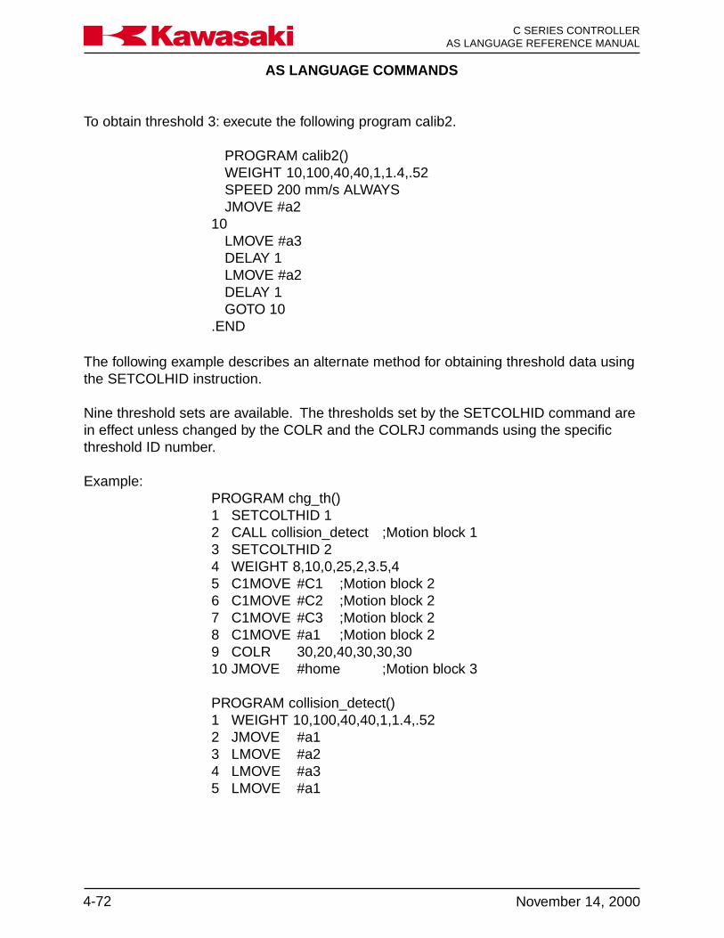
AS LANGUAGE COMMANDS
C SERIES CONTROLLERAS LANGUAGE REFERENCE MANUAL
4-72 November 14, 2000
Ka a aw s k
The following example describes an alternate method for obtaining threshold data usingthe SETCOLHID instruction.
Nine threshold sets are available. The thresholds set by the SETCOLHID command arein effect unless changed by the COLR and the COLRJ commands using the specificthreshold ID number.
Example:PROGRAM chg_th()1 SETCOLTHID 12 CALL collision_detect ;Motion block 13 SETCOLTHID 24 WEIGHT 8,10,0,25,2,3.5,45 C1MOVE #C1 ;Motion block 26 C1MOVE #C2 ;Motion block 27 C1MOVE #C3 ;Motion block 28 C1MOVE #a1 ;Motion block 29 COLR 30,20,40,30,30,3010 JMOVE #home ;Motion block 3
PROGRAM collision_detect()1 WEIGHT 10,100,40,40,1,1.4,.522 JMOVE #a13 LMOVE #a24 LMOVE #a35 LMOVE #a1
To obtain threshold 3: execute the following program calib2.
PROGRAM calib2()WEIGHT 10,100,40,40,1,1.4,.52SPEED 200 mm/s ALWAYSJMOVE #a2
10LMOVE #a3DELAY 1LMOVE #a2DELAY 1GOTO 10
.END

AS LANGUAGE COMMANDS
4-73November 14, 2000
Ka a aw s k C SERIES CONTROLLERAS LANGUAGE REFERENCE MANUAL
Threshold ID number 1 is used for motion block 1.
Threshold ID number 2 is used for motion block 2.
Threshold for motion block 3 is set by the programmer using theCOLR command.
4.10.3.4 COLLISION DETECTION AS LANGUAGE COMMANDS
The following section describes the AS Language monitor commands and programinstructions used with the collision detection function.
COLR: Monitor command and program instructionCOLRON/OFF: Monitor command and program instruction
COLRJ: Monitor command and program instructionCOLRJON/OFF Monitor command and program instruction
COLT: Monitor commandCOLTON/OFF: Monitor command
COLTJ: Monitor commandCOLTJON/OFF: Monitor command
COLMVON/OFF: Monitor command and program instructionCOLCALON/OFF: Monitor command and program instruction
WEIGHT: Monitor command and program instructionSETCOLTHID: Monitor command and program instruction
COLINIT: Monitor commandCOLSTATE: Monitor command
AS LANGUAGE COMMANDS
C SERIES CONTROLLERAS LANGUAGE REFERENCE MANUAL
4-74 November 14, 2000
Ka a aw s k
4.10.3.5 COLR
COLR JT1_threshold,JT2_threshold,···,JT6_threshold(,···JTn_threshold)
COLR: Is a monitor command and a program instruction. COLR sets thecollision threshold for JT1 through JT6 for repeat mode, and has theoption to set thresholds for addition axes (JTn).
range: 0 - 500%, a setting of 0 does not detect a collision.
When the power required to move the robot arm exceeds thethreshold settings, a collision is detected and the robot stops. Thelower the setting is the more sensitive the collision detection is. Ifthe threshold settings are set to low the load torque of the arm maycause a mis-detection.
The recommend procedure for setting thresholds is to use theCOLCAL command (automatically sets thresholds). If mis-detec-tions occur when the COLCAL command is used to set thresholds,increase the settings using a factor of times 1.2.
Example:
The following example program moves the robot from #a1 to #a2and from #a2 to #a3 (Figure 4-6) and changes the threshold in eachsection.
1 COLR 0,40,52,81,72,682 JMOVE #a13 JMOVE #a24 COLR 40,0,56,90,83,755 JMOVE #a3
JT1 does not detect a collision during the move from #a1 to #a2and (Jt1 threshold set to 0) JT2 does not detect a collision duringthe move from #a2 to #a3 (Jt2 threshold set to 0).
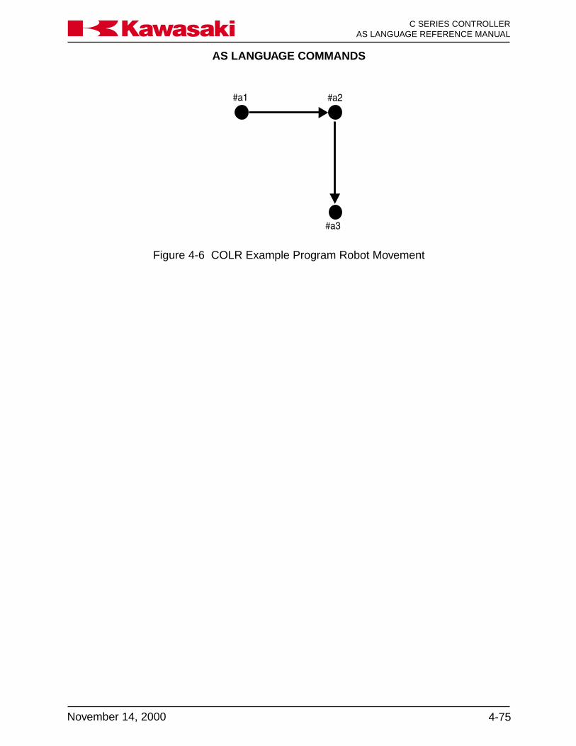
AS LANGUAGE COMMANDS
4-75November 14, 2000
Ka a aw s k C SERIES CONTROLLERAS LANGUAGE REFERENCE MANUAL
Figure 4-6 COLR Example Program Robot Movement

AS LANGUAGE COMMANDS
C SERIES CONTROLLERAS LANGUAGE REFERENCE MANUAL
4-76 November 14, 2000
Ka a aw s k
4.10.3.6 COLRON/OFF
COLRON/OFF Is a monitor command and a program instruction. The COLRONcommand is used to start collision detection monitoring in repeatmode. The COLROFF command is used to stop collision detectionmonitoring in repeat mode.
When COLRON or COLROFF is executed as a monitor command,the change is effective until controller power is turned off.
Do not add a space between COLR and ON or OFF.
To display the status of COLRON/OFF use the COLSTATE monitorcommand.
Example:
The following example program moves the robot arm from #a1 to#a4 (Figure 4-7). Collision detection is effective only during themove from #a2 to #a3.
If a spot weld is programmed at a step collision detection is ineffec-tive during the move.
1 COLR 38,40,52,81,72,682 COLROFF3 JMOVE #a14 JMOVE #a25 COLRON6 JMOVE #a37 COLROFF8 JMOVE #a4

AS LANGUAGE COMMANDS
4-77November 14, 2000
Ka a aw s k C SERIES CONTROLLERAS LANGUAGE REFERENCE MANUAL
Figure 4-7 COLRON/OFF Example Program Robot Movement
4.10.3.7 COLRJ
COLRJ JT1_threshold,JT2_threshold,···,JT6_threshold(,···JTn_threshold)
Is a monitor command and a program instruction. COLRJ sets theshock detection threshold for JT1 through JT6 for repeat mode, andhas the option to set thresholds for addition axes (JTn).
range: 0 - 200%/msec, a setting of 0 does not detect shock.
The threshold values used for shock detection must be set usingthe COLCALON and COLCALOFF commands. Shock detectionmonitors the elapsed time of a current increase. If the amount ofchange exceeds the threshold settings, the robot stops. Shockdetection reacts faster than collision detection, and is useful whenincreased sensitivity for collision detection is desired.
The recommend procedure for setting thresholds for shock detec-tion, is to use the COLCAL command (automatically sets thresh-olds).
AS LANGUAGE COMMANDS
C SERIES CONTROLLERAS LANGUAGE REFERENCE MANUAL
4-78 November 14, 2000
Ka a aw s k
4.10.3.8 COLRJON/OFF
COLRJON/OFF Is a monitor command and a program instruction. COLRJON isused to start shock detection monitoring in repeat mode.COLRJOFF is used to stop shock detection monitoring in repeatmode.
Shock detection increases the sensitivity of the collision detectionfunction and is not suitable for fast or jerky robot motions.
Use the COLSTATE command to display the status of COLRJ ONor OFF.
4.10.3.9 COLT
COLT JT1_threshold,JT2_threshold,···,JT6_threshold(,···JTn_threshold)
Is a monitor command. COLT is used to set thresholds for JT1through JT6 for teach mode, and has the option to set thresholds foraddition axes (JTn).
range: 0 - 500%, a setting of 0 does not detect a collision.
This command is effective for teach and check modes only.
The COLT command is used in the same manner as the COLRmonitor command.
4.10.3.10 COLTON/OFF
COLTON/OFF Is a monitor command. The COLTON command is used to startcollision detection monitoring in teach and check modes. TheCOLTOFF command is used to stop collision detection monitoringin teach and check modes.
When COLTON or COLTOFF is executed as a monitor command,the change is effective until controller power is turned off.
Do not add a space between COLT and ON or OFF.
To display the status of COLTON/OFF use the COLSTATE monitorcommand.

AS LANGUAGE COMMANDS
4-79November 14, 2000
Ka a aw s k C SERIES CONTROLLERAS LANGUAGE REFERENCE MANUAL
4.10.3.11 COLTJ
COLTJ JT1_threshold,JT2_threshold,···,JT6_threshold(,···JTn_threshold)
Is a monitor command. COLTJ sets the shock detection thresholdfor JT1 through JT6 for teach and check modes, and has the optionto set thresholds for addition axes (JTn).
range: 0 - 200%/msec, a setting of 0 does not detect shock.
The threshold values used for shock detection must be set usingthe COLCALON and COLCALOFF commands. Shock detectionmonitors the elapsed time of a current increase. If the amount ofchange exceeds the threshold settings, the robot stops. Shockdetection reacts faster than collision detection, and is useful whenincreased sensitivity for collision detection is desired.
The recommend procedure for setting thresholds for shock detec-tion, is to use the COLCAL command (automatically sets thresh-olds).
4.10.3.12 COLTJON/OFF
COLTJON/OFF Is a monitor command. COLTJON is used to start shock detectionmonitoring in teach and check modes. COLTJOFF is used to stopshock detection monitoring in teach and check modes.
Shock detection increases the sensitivity of the collision detectionfunction and is not suitable for fast or jerky robot motions.
Do not add a space between COLTJ and ON or OFF.
Use the COLSTATE monitor command to display the status ofCOLTJ ON or OFF.

AS LANGUAGE COMMANDS
C SERIES CONTROLLERAS LANGUAGE REFERENCE MANUAL
4-80 November 14, 2000
Ka a aw s k
4.10.3.13 COLMVON/OFF
COLMVON/OFF Is a monitor command and a program instruction. The COLMVONcommand is used to execute the stress remove motion after acollision is detected. The COLMVOFF command is used when thestress remove motion after a collision is detected is not desired.
The stress remove motion causes the robot arm to move in theopposite direction of the robot path movement, when a collision isdetected (Figure 4-8). This return motion is an arcing motion andmay cause the tool to contact the work-piece or other peripherals(Figure 4-8).
Figure 4-8 Stress Remove Motion Path
The slower the tool tip speed at a collision detection, the less stressremove motion is used by the robot.
When COLMVON or COLMVOFF is executed as a monitor com-mand, the change is effective until controller power is turned off.
Do not add a space between COLMV and ON or OFF.
Use the COLSTATE command to display the status of COLMV ONor OFF.
AS LANGUAGE COMMANDS
4-81November 14, 2000
Ka a aw s k C SERIES CONTROLLERAS LANGUAGE REFERENCE MANUAL
4.10.3.14 COLCALON/OFF
COLCALON/OFF Is a monitor command. The COLCALON command is used toobtain the maximum value of external force caused by robot motionwhile running the program. The COLCALOFF command is used atthe point in the program where collision detection is no longerdesired.
For use of the COLCALON/OFF commands refer to section 4.10.3Setting Thresholds.
4.10.3.15 WEIGHT
WEIGHT mass of tool,center of gravitylocation,inertia moment of toolrotation
Is a monitor command and a program instruction. The WEIGHTcommand is used to register tool data for tool 1-9.
The mass (weight), center of gravity location, and the inertia mo-ment of the tool (Figure 4-3) are registered with the AS LanguageWEIGHT command. The arguments follow the command separatedby comas.
The range of values are:
• load mass: 0 - load mass - kg• center of gravity location: -9999.9 - 10000.0 - mm• inertia moment: 0 - 999.99 - kg m2
Example:WEIGHT 10, 0, 74.4, 4.5, 5.1, .21, .52
For use of the WEIGHT command refer to section 4.9.3.1.

AS LANGUAGE COMMANDS
C SERIES CONTROLLERAS LANGUAGE REFERENCE MANUAL
4-82 November 14, 2000
Ka a aw s k
4.10.3.16 SETCOLTHID
SETCOLTHID threshold_number
Is a monitor command and a program instruction. TheSETCOLTHID monitor command is used to display and set thedesignated threshold number. The SETCOLTHID program instruc-tion is used to apply the threshold values of the designated thresh-old number to the robot motion program.
threshold_number: Range is 1-9, this argument cannot be omitted.
When SETCOLTHID is used as a monitor command the value ofthe designated threshold number is displayed and can be changed.The collision detection and the shock detection values for the desig-nated threshold are displayed separately for change. A message isdisplayed to allow the shock detection threshold to be continuouslyupdated, if desired. Changes are effective for the robot programrepeat motion.
When SETCOLTHID is used as a program instruction, it sets thethreshold ID number (1-9) effective for the robot motion program.This command is effective until another SETCOLTHID command isexecuted in the robot motion program.
The SETCOLTHID command and program instruction executes theauto calibration of the threshold number designated and this thresh-old is continuously updated. Before executing the SETCOLTHIDmonitor command or program instruction, the operator must initial-ize the threshold with the COLINIT monitor command. TheCOLINIT monitor command sets the value of the designated thresh-old to the default factory setting (see section 4.10.3.17).
The value of threshold numbers 1-9 are displayed using theCOLSTATE monitor command.
AS LANGUAGE COMMANDS
4-83November 14, 2000
Ka a aw s k C SERIES CONTROLLERAS LANGUAGE REFERENCE MANUAL
4.10.3.17 COLINIT
COLINIT threshold_number
Is a monitor command. The COLINIT command is used to setcollision detection parameters to default factory settings.
threshold_number: Range is 1-9. The threshold number argument can be omitted.When the threshold number is omitted all threshold parameters areset to default factory settings.
When a threshold number is designated the settings for collisiondetection and shock detection for the designated threshold numberare set to 0.
4.10.3.18 COLSTATE
COLSTATE threshold_number
Is a monitor command. The COLSTATE command is used to dis-play current collision detection and shock detection parameters.
threshold_number: Range is 1-9. The threshold number argument can be omitted.
The value of each axis threshold and the current setting of eachcollision detection mode are displayed (figure 4-9 and 4-10).
COLR: Collision detection in repeat mode ON/OFFCOLRJ: Shock detection in repeat mode ON/OFFCOLT: Collision detection in teach mode ON/OFFCOLTJ: Shock detection in teach mode ON/OFFCOLESCMV: Stress remove motion ON/OFFCOLCAL: Automatic calibration mode ON/OFFVCOLR: Collision detection in repeat mode ON/OFF
(OFF during spot weld execution)VCOLT: Collision detection in teach mode ON/OFF
(OFF during spot weld execution)

AS LANGUAGE COMMANDS
C SERIES CONTROLLERAS LANGUAGE REFERENCE MANUAL
4-84 November 14, 2000
Ka a aw s k
Figure 4-10 COLSTATE Command Display with Threshold Number
Figure 4-9 COLSTATE Command Display without Threshold Number

AS LANGUAGE COMMANDS
4-85November 14, 2000
Ka a aw s k C SERIES CONTROLLERAS LANGUAGE REFERENCE MANUAL
4.10.3.19 COLLISION DETECTION ERROR CODE
ERROR CODE -1902 JT* Collision or abnormal disturb is detected
Occurs when the controller determines a collision has occurred because torque valuesfor the motors cannot be determined.
⇒ Move the tool or the robot arm away from the obstacle.⇒ Ensure the tool registration data is accurate.⇒ If a collision did not occur and the error reoccurs, increase the threshold setting using
a factor of times 1.2.
4.10.3.20 COLLISION DETECTION TROUBLESHOOTING
Constant mis-detection:
1. Ensure the tool registration data is accurate.2. Reset thresholds using auto-calibration.3. Manually reset the thresholds using a factor of times 1.2.
Collision detection reaction is slow:
1. Ensure the tool registration data is accurate.2. Reset thresholds using auto-calibration.
Collision is not detected:
1. Use the COLSTATE command to determine if collision detection is set to ON andthreshold values for the axes are not set to 0.
Stress remove motion is too large:
1. If the stress remove motion causes the tooling to interfere with the work-piece orperipherals, use the COLMVOFF command to make the stress remove motionineffective.
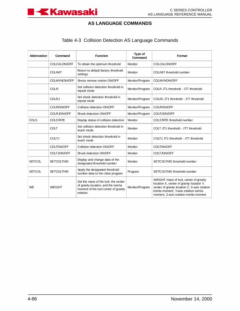
AS LANGUAGE COMMANDS
C SERIES CONTROLLERAS LANGUAGE REFERENCE MANUAL
4-86 November 14, 2000
Ka a aw s k
Abbrevation Command Function Type ofCommand
Format
COLCALON/OFF To obtain the optimum threshold Monitor COLCALON/OFF
COLINITReturn to default factory thresholdsettings
Monitor COLINIT threshold number
COLMVNON/OFF Stress remove motion ON/OFF Monitor/Program COLMVNON/OFF
COLRSet collision detection threshold inrepeat mode
Monitor/Program COLR JT1 threshold - JT7 threshold
COLRJSet shock detection threshold inrepeat mode
Monitor/Program COLRJ JT1 threshold - JT7 threshold
COLRON/OFF Collision detection ON/OFF Monitor/Program COLRON/OFF
COLRJON/OFF Shock detection ON/OFF Monitor/Program COLRJON/OFF
COLS COLSTATE Display status of collision detection Monitor COLSTATE threshold number
COLTSet collision detection threshold inteach mode
Monitor COLT JT1 threshold - JT7 threshold
COLTJSet shock detection threshold inteach mode
Monitor COLTJ JT1 threshold - JT7 threshold
COLTON/OFF Collision detection ON/OFF Monitor COLTON/OFF
COLTJON/OFF Shock detection ON/OFF Monitor COLTJON/OFF
SETCOL SETCOLTHIDDisplay and change data of thedesignated threshold number
Monitor SETCOLTHID threshold number
SETCOL SETCOLTHIDApply the designated thresholdnumber data to the robot program
Program SETCOLTHID threshold number
WE WEIGHT
Set the mass of the tool, the centerof gravity location, and the inertiamoment of the tool center of gravityrotation.
Monitor/Program
WEIGHT mass of tool, center of gravitylocation X, center of gravity location Y,center of gravity location Z, X-axis rotationinertia moment, Y-axis rotation inertiamoment, Z-axis rotation inertia moment
Table 4-3 Collision Detection AS Language Commands
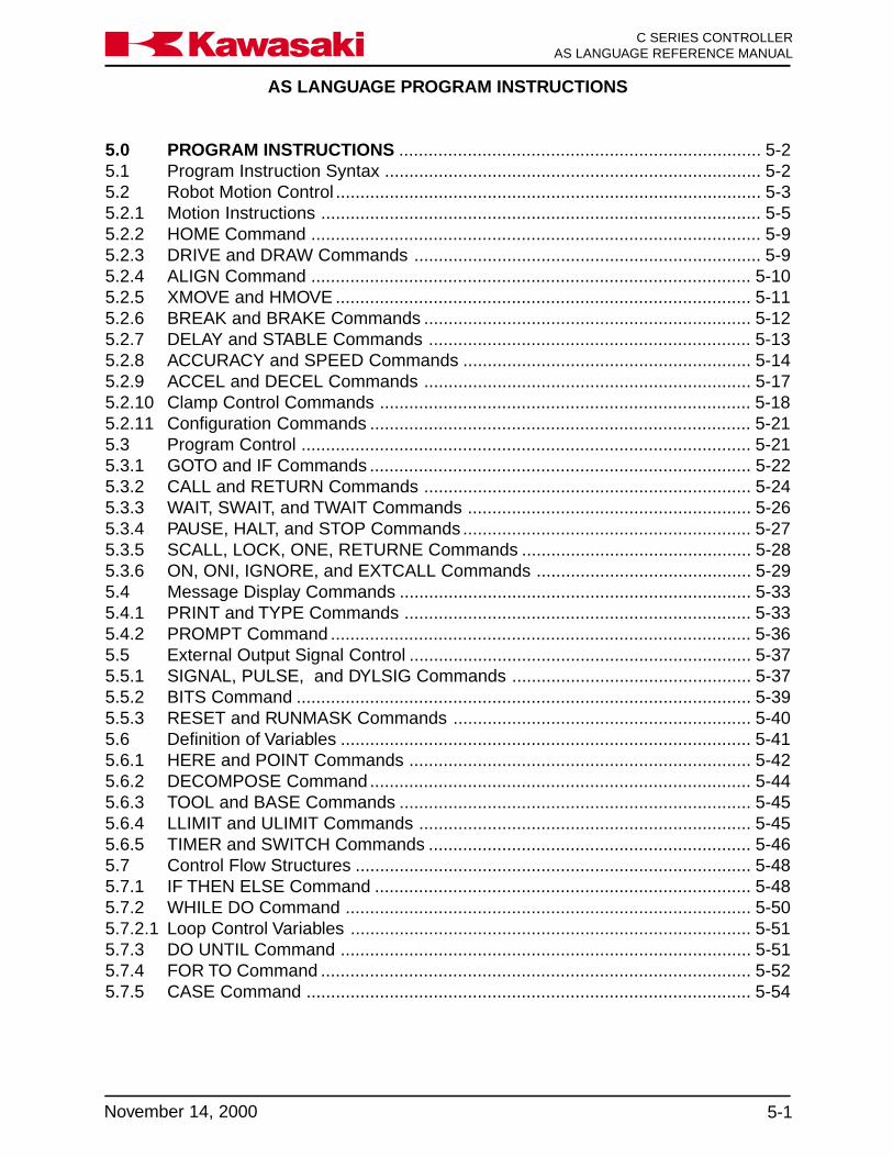
AS LANGUAGE PROGRAM INSTRUCTIONS
5-1November 14, 2000
Ka a aw s k C SERIES CONTROLLERAS LANGUAGE REFERENCE MANUAL
5.0 PROGRAM INSTRUCTIONS .......................................................................... 5-25.1 Program Instruction Syntax ............................................................................. 5-25.2 Robot Motion Control ....................................................................................... 5-35.2.1 Motion Instructions .......................................................................................... 5-55.2.2 HOME Command ............................................................................................ 5-95.2.3 DRIVE and DRAW Commands ....................................................................... 5-95.2.4 ALIGN Command .......................................................................................... 5-105.2.5 XMOVE and HMOVE ..................................................................................... 5-115.2.6 BREAK and BRAKE Commands ................................................................... 5-125.2.7 DELAY and STABLE Commands .................................................................. 5-135.2.8 ACCURACY and SPEED Commands ........................................................... 5-145.2.9 ACCEL and DECEL Commands ................................................................... 5-175.2.10 Clamp Control Commands ............................................................................ 5-185.2.11 Configuration Commands .............................................................................. 5-215.3 Program Control ............................................................................................ 5-215.3.1 GOTO and IF Commands .............................................................................. 5-225.3.2 CALL and RETURN Commands ................................................................... 5-245.3.3 WAIT, SWAIT, and TWAIT Commands .......................................................... 5-265.3.4 PAUSE, HALT, and STOP Commands ........................................................... 5-275.3.5 SCALL, LOCK, ONE, RETURNE Commands ............................................... 5-285.3.6 ON, ONI, IGNORE, and EXTCALL Commands ............................................ 5-295.4 Message Display Commands ........................................................................ 5-335.4.1 PRINT and TYPE Commands ....................................................................... 5-335.4.2 PROMPT Command ...................................................................................... 5-365.5 External Output Signal Control ...................................................................... 5-375.5.1 SIGNAL, PULSE, and DYLSIG Commands ................................................. 5-375.5.2 BITS Command ............................................................................................. 5-395.5.3 RESET and RUNMASK Commands ............................................................. 5-405.6 Definition of Variables .................................................................................... 5-415.6.1 HERE and POINT Commands ...................................................................... 5-425.6.2 DECOMPOSE Command .............................................................................. 5-445.6.3 TOOL and BASE Commands ........................................................................ 5-455.6.4 LLIMIT and ULIMIT Commands .................................................................... 5-455.6.5 TIMER and SWITCH Commands .................................................................. 5-465.7 Control Flow Structures ................................................................................. 5-485.7.1 IF THEN ELSE Command ............................................................................. 5-485.7.2 WHILE DO Command ................................................................................... 5-505.7.2.1 Loop Control Variables .................................................................................. 5-515.7.3 DO UNTIL Command .................................................................................... 5-515.7.4 FOR TO Command ........................................................................................ 5-525.7.5 CASE Command ........................................................................................... 5-54

AS LANGUAGE PROGRAM INSTRUCTIONS
C SERIES CONTROLLERAS LANGUAGE REFERENCE MANUAL
5-2 November 14, 2000
Ka a aw s k
5.0 PROGRAM INSTRUCTIONS
5.1 PROGRAM INSTRUCTION SYNTAX
The complete format of a valid AS program line is:
step number label <space> program instruction <space> argument ;comment
1? 100 JMOVE pt1 ;pounce2? JMOVE pt2 ;Anything after the semicolon3? line: JMOVE pt3 ;is ignored by the system.
The step number is automatically inserted by the AS editor so all steps are numberedconsecutively. The optional step label is used to identify a particular program line for abranching instruction elsewhere in the program. The optional label can be either apositive integer value or an alphanumeric name no longer than fifteen characters. If analphanumeric label is used, it must be followed by a colon. The semicolon is used in theAS system to represent a comment. Any text that appears after the semicolon is ig-nored by the system.
One space is required between a program instruction, and a label, or an argument in aline. If more spaces are entered the entry is accepted and the extra spaces are auto-matically removed when the line is entered.
All AS instructions/commands in this unit are shown in uppercase letters with argumentsshown in lowercase letters. Program instructions and their arguments are typed into aprogram using any combination of uppercase or lowercase letters. The AS editor con-verts the case of the input to conform to the convention of uppercase for all AS key-words and lowercase for all user variables.

AS LANGUAGE PROGRAM INSTRUCTIONS
5-3November 14, 2000
Ka a aw s k C SERIES CONTROLLERAS LANGUAGE REFERENCE MANUAL
5.2 ROBOT MOTION CONTROL
JMOVE (JM) Starts a joint interpolated motion.
LMOVE (LM) Starts a linear interpolated motion.
JAPPROACH (JA) Starts a joint interpolated motion to approach thelocation keeping the specified distance.
LAPPROACH (LA) Starts a linear interpolated motion to approach thelocation keeping the specified distance.
JDEPART (JD) Backs the tool the specified distance from the currentlocation in a joint interpolated motion.
LDEPART (LD) Backs the tool the specified distance from the currentlocation in a linear interpolated motion.
HOME (HO) Moves the robot to the home position.
DRIVE (DRI) Moves a single joint.
DRAW (DRA) Moves the robot by the amount given in XYZ compo-nents.
TDRAW (TD) Moves the robot by the amount given in tool XYZcomponents.
ALIGN (AL) Aligns Z-axis of the robot tool.
XMOVE (X) Moves to next location until specified signal is received
HMOVE (HM) Starts a hybrid interpolated motion
C1MOVE (C1) Starts move for a circular interpolated motion (option).
C2MOVE (C2) Ends move for a circular interpolated motion (option).
BREAK (BRE) Ensures current robot motion is completed.
BRAKE (BRA) Stops the current robot motion immediately.
DELAY (DEL) Stops robot motion for the specified period of time.
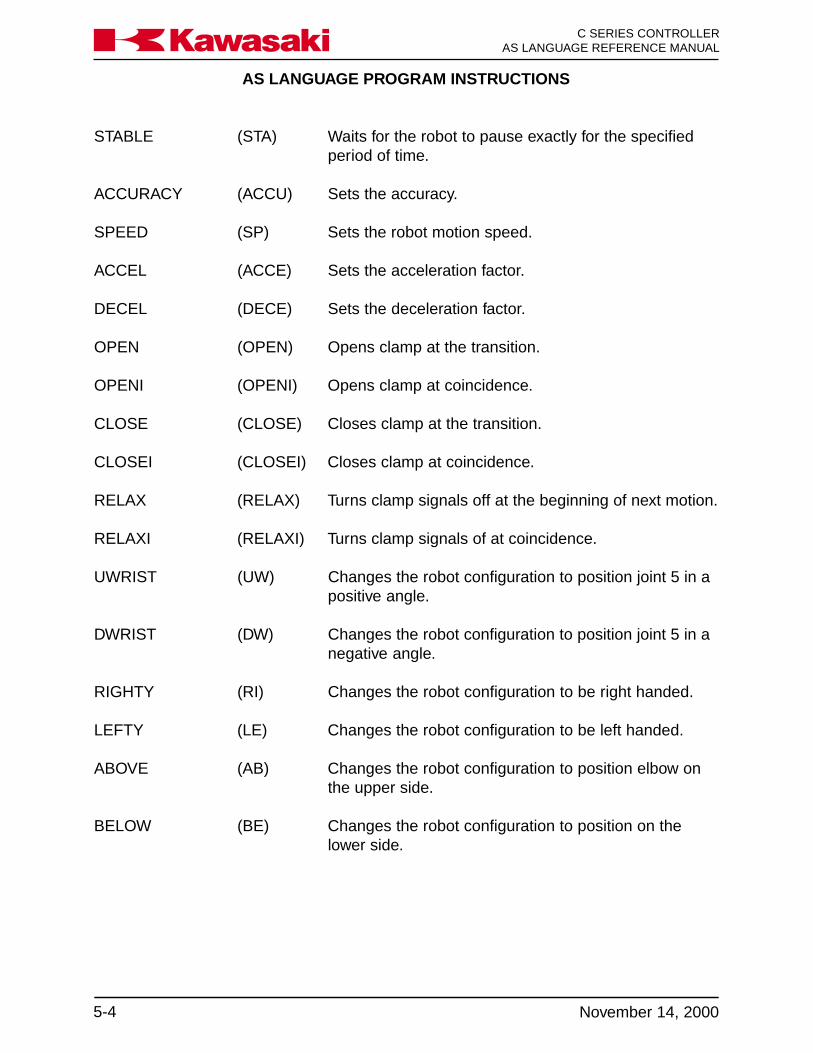
AS LANGUAGE PROGRAM INSTRUCTIONS
C SERIES CONTROLLERAS LANGUAGE REFERENCE MANUAL
5-4 November 14, 2000
Ka a aw s k
STABLE (STA) Waits for the robot to pause exactly for the specifiedperiod of time.
ACCURACY (ACCU) Sets the accuracy.
SPEED (SP) Sets the robot motion speed.
ACCEL (ACCE) Sets the acceleration factor.
DECEL (DECE) Sets the deceleration factor.
OPEN (OPEN) Opens clamp at the transition.
OPENI (OPENI) Opens clamp at coincidence.
CLOSE (CLOSE) Closes clamp at the transition.
CLOSEI (CLOSEI) Closes clamp at coincidence.
RELAX (RELAX) Turns clamp signals off at the beginning of next motion.
RELAXI (RELAXI) Turns clamp signals of at coincidence.
UWRIST (UW) Changes the robot configuration to position joint 5 in apositive angle.
DWRIST (DW) Changes the robot configuration to position joint 5 in anegative angle.
RIGHTY (RI) Changes the robot configuration to be right handed.
LEFTY (LE) Changes the robot configuration to be left handed.
ABOVE (AB) Changes the robot configuration to position elbow onthe upper side.
BELOW (BE) Changes the robot configuration to position on thelower side.

AS LANGUAGE PROGRAM INSTRUCTIONS
5-5November 14, 2000
Ka a aw s k C SERIES CONTROLLERAS LANGUAGE REFERENCE MANUAL
5.2.1 MOTION INSTRUCTIONS
JMOVE location, clamp_numberLMOVE
Starts the robot motion to the position defined by the given location.
JMOVE: Moves in joint interpolated motion.LMOVE: Moves in linear interpolated motion.
location: Represents the destination (transformation value, precision value,location function, or compound transformation value).
The JMOVE instruction initiates a joint interpolated (point-to-point)motion. The robot moves in a path that interpolates respective jointangles between the current position and the destination position.
The LMOVE instruction initiates a linear interpolated motion and therobot tool center point moves along a straight line path.
clamp number: The optional clamp number argument allows the programmer todesignate a clamp to open or close.
a positive number opens the clamp and a negative number closesthe clamp.
JMOVE start,2 ;moves to location start and opens clamp number 2.
JMOVE pick,-2 ;moves to location pick and closes clamp number 2.
If the optional clamp number is omitted, clamp signals are notchanged.
JAPPRO location, distanceLAPPRO
Moves the tool to the location, offset the specified distance alongthe tool Z-axis.
JAPPRO: Moves in joint interpolated motion.LAPPRO: Moves in linear interpolated motion.
location: Defines the destination (either transformation or precision value).

AS LANGUAGE PROGRAM INSTRUCTIONS
C SERIES CONTROLLERAS LANGUAGE REFERENCE MANUAL
5-6 November 14, 2000
Ka a aw s k
distance: Distance along the tool Z-axis, between the specified location andthe actual destination in millimeters. A positive distance sets thetorch back (tool negative Z-axis) from the specified location; anegative distance offsets the tool forward (tool positive Z-axis) ofthe specified location.
In the JAPPRO and LAPPRO instructions, the tool direction isdetermined by the location argument, and the actual tool destina-tion is set to approach the specified location by the given distancealong the tool Z-axis (Figure 5-1). Refer to figure 5-2 for tool orien-tation.
Figure 5-1 JAPPRO/LAPPRO Commands
In the preceding example, step 2 causes the robot to stop 100 mmaway from location bb in the tool -z direction. The robot moves tolocation bb when step 3 is executed. If a negative value is specifiedin step 2, the robot moves 100 mm beyond location bb in the tool +zdirection.

AS LANGUAGE PROGRAM INSTRUCTIONS
5-7November 14, 2000
Ka a aw s k C SERIES CONTROLLERAS LANGUAGE REFERENCE MANUAL
Figure 5-2 Tool Orientation
JDEPART distanceLDEPART
Moves the tool by the distance given along the current Z-axis of thetool.
JDEPART: Moves in joint interpolated motionLDEPART: Moves in linear interpolated motion.
Distance: Distance along the tool Z-axis, between the specified location andthe actual destination in millimeters. A positive distance sets thetool back (tool negative Z-axis) from the current location; a negativedistance offsets the tool forward (tool positive Z-axis) of the speci-fied location (Figure 5-3). Refer to figure 5-2 for tool orientation.

AS LANGUAGE PROGRAM INSTRUCTIONS
C SERIES CONTROLLERAS LANGUAGE REFERENCE MANUAL
5-8 November 14, 2000
Ka a aw s k
Figure 5-3 JDEPART/LDEPART Commands
The LDEPART command at step 4, in the following example, movesthe robot 100 mm away from the location bb (step3).
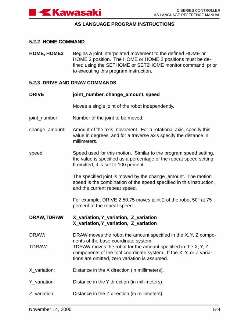
AS LANGUAGE PROGRAM INSTRUCTIONS
5-9November 14, 2000
Ka a aw s k C SERIES CONTROLLERAS LANGUAGE REFERENCE MANUAL
5.2.2 HOME COMMAND
HOME, HOME2 Begins a joint interpolated movement to the defined HOME orHOME 2 position. The HOME or HOME 2 positions must be de-fined using the SETHOME or SET2HOME monitor command, priorto executing this program instruction.
5.2.3 DRIVE AND DRAW COMMANDS
DRIVE joint_number, change_amount, speed
Moves a single joint of the robot independently.
joint_number: Number of the joint to be moved.
change_amount: Amount of the axis movement. For a rotational axis, specify thisvalue in degrees, and for a traverse axis specify the distance inmillimeters.
speed: Speed used for this motion. Similar to the program speed setting,the value is specified as a percentage of the repeat speed setting.If omitted, it is set to 100 percent.
The specified joint is moved by the change_amount. The motionspeed is the combination of the speed specified in this instruction,and the current repeat speed.
For example, DRIVE 2,50,75 moves joint 2 of the robot 50° at 75percent of the repeat speed.
DRAW, TDRAW X_variation, Y_variation, Z_variationX_variation, Y_variation, Z_variation
DRAW: DRAW moves the robot the amount specified in the X, Y, Z compo-nents of the base coordinate system.
TDRAW: TDRAW moves the robot for the amount specified in the X, Y, Zcomponents of the tool coordinate system. If the X, Y, or Z varia-tions are omitted, zero variation is assumed.
X_variation: Distance in the X direction (in millimeters).
Y_variation: Distance in the Y direction (in millimeters).
Z_variation: Distance in the Z direction (in millimeters).
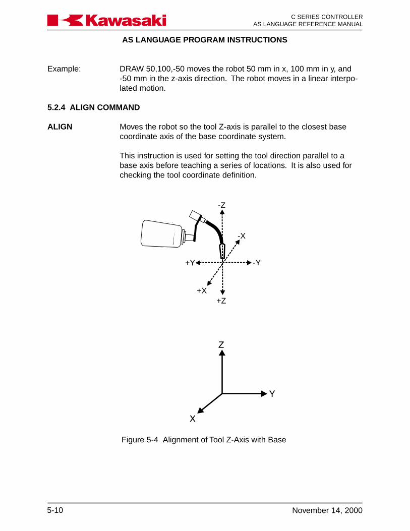
AS LANGUAGE PROGRAM INSTRUCTIONS
C SERIES CONTROLLERAS LANGUAGE REFERENCE MANUAL
5-10 November 14, 2000
Ka a aw s k
Figure 5-4 Alignment of Tool Z-Axis with Base
Example: DRAW 50,100,-50 moves the robot 50 mm in x, 100 mm in y, and-50 mm in the z-axis direction. The robot moves in a linear interpo-lated motion.
5.2.4 ALIGN COMMAND
ALIGN Moves the robot so the tool Z-axis is parallel to the closest basecoordinate axis of the base coordinate system.
This instruction is used for setting the tool direction parallel to abase axis before teaching a series of locations. It is also used forchecking the tool coordinate definition.
-Z
-X
-Y+Y
+X+Z
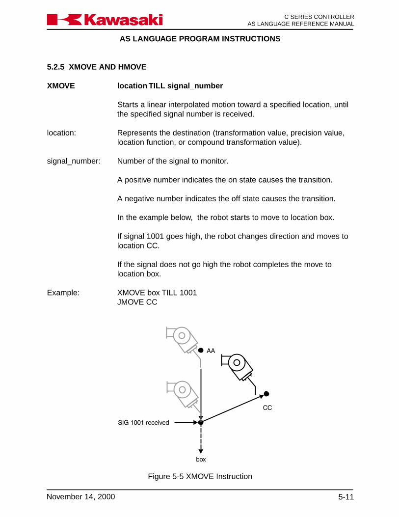
AS LANGUAGE PROGRAM INSTRUCTIONS
5-11November 14, 2000
Ka a aw s k C SERIES CONTROLLERAS LANGUAGE REFERENCE MANUAL
5.2.5 XMOVE AND HMOVE
XMOVE location TILL signal_number
Starts a linear interpolated motion toward a specified location, untilthe specified signal number is received.
location: Represents the destination (transformation value, precision value,location function, or compound transformation value).
signal_number: Number of the signal to monitor.
A positive number indicates the on state causes the transition.
A negative number indicates the off state causes the transition.
In the example below, the robot starts to move to location box.
If signal 1001 goes high, the robot changes direction and moves tolocation CC.
If the signal does not go high the robot completes the move tolocation box.
Example: XMOVE box TILL 1001JMOVE CC
Figure 5-5 XMOVE Instruction
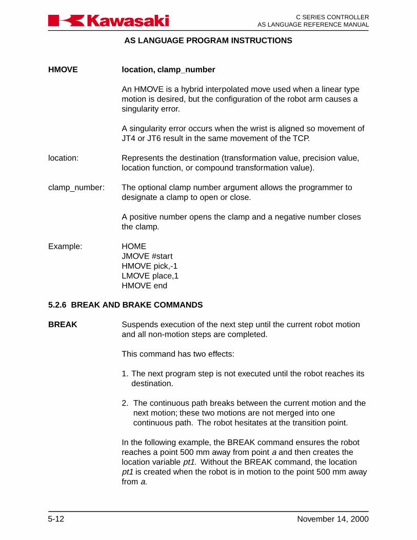
AS LANGUAGE PROGRAM INSTRUCTIONS
C SERIES CONTROLLERAS LANGUAGE REFERENCE MANUAL
5-12 November 14, 2000
Ka a aw s k
HMOVE location, clamp_number
An HMOVE is a hybrid interpolated move used when a linear typemotion is desired, but the configuration of the robot arm causes asingularity error.
A singularity error occurs when the wrist is aligned so movement ofJT4 or JT6 result in the same movement of the TCP.
location: Represents the destination (transformation value, precision value,location function, or compound transformation value).
clamp_number: The optional clamp number argument allows the programmer todesignate a clamp to open or close.
A positive number opens the clamp and a negative number closesthe clamp.
Example: HOMEJMOVE #startHMOVE pick,-1LMOVE place,1HMOVE end
5.2.6 BREAK AND BRAKE COMMANDS
BREAK Suspends execution of the next step until the current robot motionand all non-motion steps are completed.
This command has two effects:
1. The next program step is not executed until the robot reaches itsdestination.
2. The continuous path breaks between the current motion and thenext motion; these two motions are not merged into onecontinuous path. The robot hesitates at the transition point.
In the following example, the BREAK command ensures the robotreaches a point 500 mm away from point a and then creates thelocation variable pt1. Without the BREAK command, the locationpt1 is created when the robot is in motion to the point 500 mm awayfrom a.
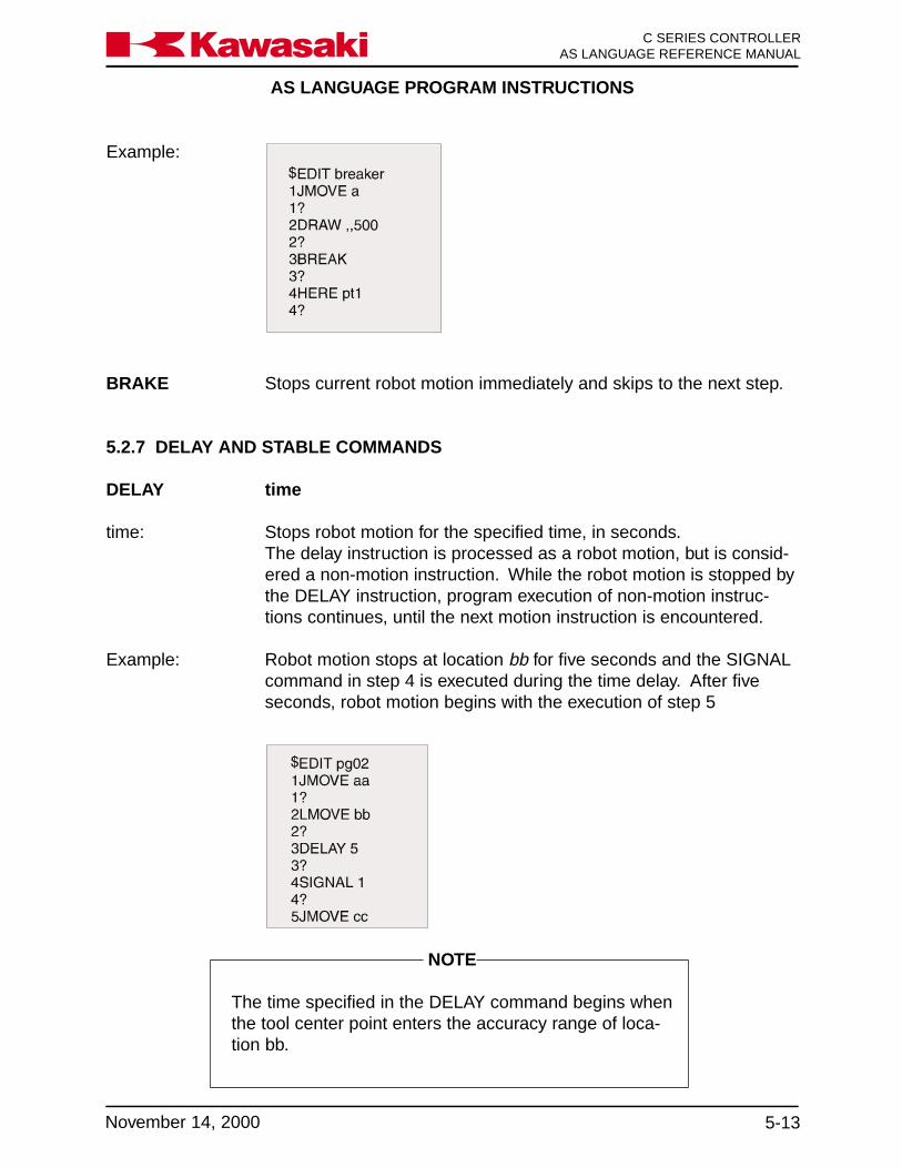
AS LANGUAGE PROGRAM INSTRUCTIONS
5-13November 14, 2000
Ka a aw s k C SERIES CONTROLLERAS LANGUAGE REFERENCE MANUAL
NOTE
The time specified in the DELAY command begins whenthe tool center point enters the accuracy range of loca-tion bb.
BRAKE Stops current robot motion immediately and skips to the next step.
5.2.7 DELAY AND STABLE COMMANDS
DELAY time
time: Stops robot motion for the specified time, in seconds.The delay instruction is processed as a robot motion, but is consid-ered a non-motion instruction. While the robot motion is stopped bythe DELAY instruction, program execution of non-motion instruc-tions continues, until the next motion instruction is encountered.
Example: Robot motion stops at location bb for five seconds and the SIGNALcommand in step 4 is executed during the time delay. After fiveseconds, robot motion begins with the execution of step 5
Example:

AS LANGUAGE PROGRAM INSTRUCTIONS
C SERIES CONTROLLERAS LANGUAGE REFERENCE MANUAL
5-14 November 14, 2000
Ka a aw s k
Example: Accuracy is set at 100 mm for steps 2 through 4. The accuracy forstep 6 is 1 mm and 100 mm for step 7, since ALWAYS is not speci-fied in step 6.
5.2.8 ACCURACY AND SPEED COMMANDS
ACCURACY value ALWAYS
Sets robot positioning accuracy.
value: Distance for accuracy range in millimeters.
ALWAYS: If omitted, only the next motion instruction is affected. When theargument ALWAYS is specified, the accuracy setting is effectiveuntil the next ACCURACY instruction is executed.
In an AS Language program the default accuracy is used whenaccuracy is not defined at the beginning of the program.
STABLE time
time: Causes the robot to pause for a specified time when the robotreaches the programmed point.If the robot is placed in a hold condition, the time specified by theSTABLE instruction is reset. When the robot is returned to run, thetiming cycle starts over.
This instruction is not affected by the accuracy setting as the DE-LAY instruction. DELAY allows timing to start when the robot iswithin the accuracy range of the point. The STABLE instructiondoes not allow timing to begin until the robot reaches the exactlocation.

AS LANGUAGE PROGRAM INSTRUCTIONS
5-15November 14, 2000
Ka a aw s k C SERIES CONTROLLERAS LANGUAGE REFERENCE MANUAL
SPEED value ALWAYS
Sets the robot motion speed for program steps.
value: The program step speed set as a percentage of monitor speed.Specify the speed in percentages within the range 0.01 to 100percent. If mm/s (mm/second) or mm/min (mm/minute) is specifiedafter the value, the absolute speed is set.
ALWAYS: When the argument ALWAYS is specified, the setting is effectiveuntil the next SPEED instruction is executed. When not specified,only the next robot motion is affected.
This command sets robot motion speed as a percentage of monitorspeed. The actual robot speed is determined by the product of theprogram speed (set by this instruction) and the monitor speed (setby the SPEED command in the monitor mode).
For a timed motion, enter the time value followed by an “s” (sec-onds).
When a value without a unit is designated, the value is accepted asa percentage of the maximum speed.
When an absolute speed is specified, it represents the tool tipspeed in linear interpolated motion. Maximum tool tip speed isavailable from the robot specifications sheet for each robot model.
For joint interpolated motion, the joint speed is calculated andconverted into an absolute value expressed in mm/s.
Examples: SPEED 50 Sets the next motion speed to 50%.
SPEED 75 ALWAYS Sets the motion speed to 75% untilchanged by another SPEED command.
SPEED 20 mm/s Sets the tool tip speed to 20 mm persecond for the next linear motion command.
SPEED 6000 mm/min Sets the tool tip speed to 6000 mm perminute for the next linear motion command.
SPEED 8s sets the time to complete the next motion.

AS LANGUAGE PROGRAM INSTRUCTIONS
C SERIES CONTROLLERAS LANGUAGE REFERENCE MANUAL
5-16 November 14, 2000
Ka a aw s k
Monitor speed is set at 100 percent. Robot speed for steps 2, and 3is 1,000 mm/s, and for step 4 jmove cc, the speed is converted toan equivalent value. Robot speed for step 6 is 30 percent, and thespeed for step 7 is 1,000 mm/s since always is not specified in step5.
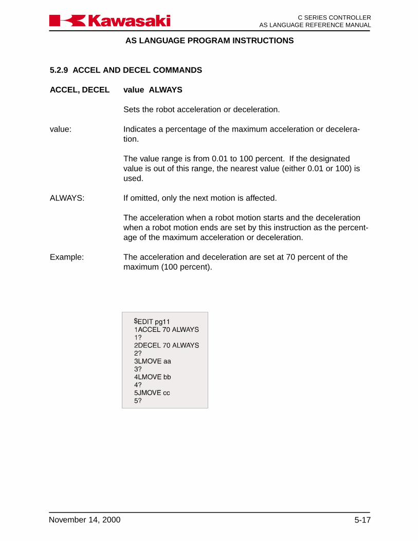
AS LANGUAGE PROGRAM INSTRUCTIONS
5-17November 14, 2000
Ka a aw s k C SERIES CONTROLLERAS LANGUAGE REFERENCE MANUAL
5.2.9 ACCEL AND DECEL COMMANDS
ACCEL, DECEL value ALWAYS
Sets the robot acceleration or deceleration.
value: Indicates a percentage of the maximum acceleration or decelera-tion.
The value range is from 0.01 to 100 percent. If the designatedvalue is out of this range, the nearest value (either 0.01 or 100) isused.
ALWAYS: If omitted, only the next motion is affected.
The acceleration when a robot motion starts and the decelerationwhen a robot motion ends are set by this instruction as the percent-age of the maximum acceleration or deceleration.
Example: The acceleration and deceleration are set at 70 percent of themaximum (100 percent).
AS LANGUAGE PROGRAM INSTRUCTIONS
C SERIES CONTROLLERAS LANGUAGE REFERENCE MANUAL
5-18 November 14, 2000
Ka a aw s k
5.2.10 CLAMP CONTROL COMMANDS
Clamp control parameters are set in auxiliary function 114.
OPEN clamp_number
Is used to set the output signal to open the clamp at the beginningof the next robot motion.
clamp_number: Specifies the clamp to open. Eight clamps are available.
If the clamp_number is omitted, clamp one is specified.
OPENI clamp_number
Is used to set the output signal to open the clamp. The OPENIcommand causes a BREAK to occur if continuous path motion is inprogress.
The output signal to open the clamp is sent at the completion of thecurrent motion.
clamp_number: Specifies the clamp to open. Eight clamps are available.
If the clamp_number is omitted, clamp one is specified.
Figure 5-7 shows the differences between the OPEN and OPENIcommands.

AS LANGUAGE PROGRAM INSTRUCTIONS
5-19November 14, 2000
Ka a aw s k C SERIES CONTROLLERAS LANGUAGE REFERENCE MANUAL
CLOSE clamp_number
Is used to set the output signal to close the clamp at the beginningof the next robot motion.
clamp_number: Specifies the clamp to close. Eight clamps are available.
If the clamp_number is omitted, clamp one is specified.
CLOSEI clamp_number
The CLOSEI command is used to set the output signal to close theclamp. The CLOSEI command causes a BREAK to occur if con-tinuous path motion is in progress.
The output signal to close the clamp is sent at the completion of thecurrent motion.
Figure 5-7 OPEN and OPENI Commands

AS LANGUAGE PROGRAM INSTRUCTIONS
C SERIES CONTROLLERAS LANGUAGE REFERENCE MANUAL
5-20 November 14, 2000
Ka a aw s k
clamp_number: Specifies the clamp to close. Eight clamps are available.
If the clamp number is omitted, clamp one is specified.
RELAX clamp_number
Sets the output signals to release pneumatic pressure at the clampat the beginning of the next robot motion.
clamp_number: Specifies the clamp to be relaxed. Eight clamps are available.
If the clamp number is omitted, clamp one is specified.
RELAXI clamp_number
Sets the output signals to release pneumatic pressure at the clamp.
The RELAXI command causes a BREAK to occur if continuouspath motion is in progress. The output signals to release pneumaticpressure to the clamp are set at the completion of the current mo-tion.
clamp_number: Specifies the clamp to be relaxed. Eight clamps are available.
If the clamp number is omitted, clamp one is specified.
UWRISTDWRIST Forces a configuration (posture) change during the next motion so
the angle of Joint 5 has a positive value for an UWRIST commandand a negative value for a DWRIST command.
The UWRIST and DWRIST commands are not effective duringlinear interpolated motion or for a precision location.
AS LANGUAGE PROGRAM INSTRUCTIONS
5-21November 14, 2000
Ka a aw s k C SERIES CONTROLLERAS LANGUAGE REFERENCE MANUAL
5.2.11 CONFIGURATION COMMANDS
RIGHTYLEFTY Forces a robot configuration (posture) change during the next
motion so the first three joints of the robot arm are configured toresemble a person’s right or left arm.
The RIGHTY and LEFTY commands are not effective during linearinterpolated motion or for a precision location.
ABOVEBELOW Forces a robot configuration (posture) change during the next
motion so the “elbow joint” (joint 3) is configured in an above orbelow position relative to the wrist.
The ABOVE and BELOW commands are not effective during linearinterpolated motion or for a precision location.
5.3 PROGRAM CONTROL
GOTO Causes program execution to jump to a substitute program.IF Performs a conditional jump command.CALL Causes execution to branch to a subroutine.RETURN Returns control to the caller program.WAIT Causes execution to wait until the specified condition is set.SWAIT Causes execution to wait until the desired signal states are set.TWAIT Causes execution to wait until the specified time has elapsed.PAUSE Stops execution temporarily.HALT Stops execution and does not allow it to be resumed.STOP Terminates the current execution cycle.SCALL Calls a program assigned to a string variable.LOCK Sets subroutine priorities for process control programs.ONE Used in process control programs to call a program at an error.RETURNE Used in process control programs to return to the step after the step
where an error occurred.ON Starts monitoring the signal for interrupt handling.ONI Starts monitoring the signal for immediate interrupt handling.IGNORE Cancels signal monitoring started by the ON or ONI instruction.EXTCALL Selects an external program number via RPS.

AS LANGUAGE PROGRAM INSTRUCTIONS
C SERIES CONTROLLERAS LANGUAGE REFERENCE MANUAL
5-22 November 14, 2000
Ka a aw s k
5.3.1 GOTO AND IF COMMANDS
GOTO Iabel IF condition
This instruction causes execution to branch to the step which hasthe specified label. If a condition is given, execution branches onlywhen the condition is TRUE. Otherwise, execution proceeds to thenext step in order.
label: Label assigned to a program step which execution branches to.Labels can be a combination of alphanumeric characters up tofifteen characters long.
IF: condition: Condition of the branch (represented in logical expression). If
omitted, execution branches unconditionally.
Examples: GOTO 100 causes execution to branch unconditionally to the stepwith label 100. If there is no line with the label 100 in the sameprogram, an error occurs.
GOTO 200 IF n ==3 causes execution to branch to a step with label200 if variable n is equal to 3, otherwise, execution proceeds to thenext step.
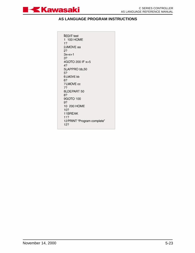
AS LANGUAGE PROGRAM INSTRUCTIONS
5-23November 14, 2000
Ka a aw s k C SERIES CONTROLLERAS LANGUAGE REFERENCE MANUAL

AS LANGUAGE PROGRAM INSTRUCTIONS
C SERIES CONTROLLERAS LANGUAGE REFERENCE MANUAL
5-24 November 14, 2000
Ka a aw s k
IF condition GOTO label
Causes execution to branch to the specified label if the condition isTRUE.
condition: Logical expression evaluated during step execution.
Example: n==0, n>3, m+n>0
GOTO:label: Label of program step to which execution branches to.
Examples: IF N>3 GOTO 100If the value of the integer variable n is greater than 3, executionbranches to the step with label 100, otherwise, execution continueswith the next step.
IF SIG(1001) AND SIG(-1002) GOTO 250If input signal 1001 is ON and input signal 1002 is OFF, executionbranches to the step with label 250, otherwise, execution continueswith the next step.
5.3.2 CALL AND RETURN COMMANDS
CALL program_name
Causes execution to jump to the specified program (subroutine).After completion of the subroutine, execution returns to the stepfollowing the CALL instruction.
This instruction suspends execution of the current program. Execu-tion branches to the first step of the subroutine program.
A subroutine cannot be called by both the robot control programand a PC program at the same time.
Multiple calls of a subroutine (calling another subroutine from theone being executed) are possible, up to twenty maximum.
A subroutine cannot call itself. The example on the next pageillustrates the CALL instruction.
program_name: Name of the program to call.
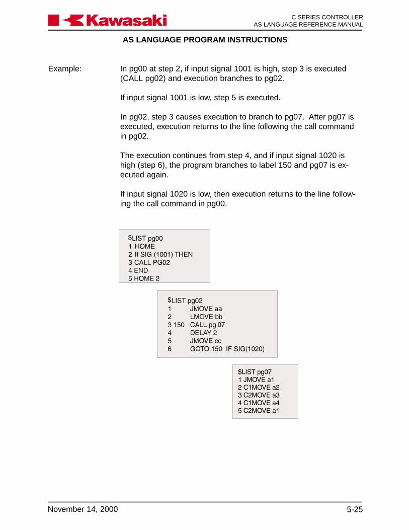
AS LANGUAGE PROGRAM INSTRUCTIONS
5-25November 14, 2000
Ka a aw s k C SERIES CONTROLLERAS LANGUAGE REFERENCE MANUAL
Example: In pg00 at step 2, if input signal 1001 is high, step 3 is executed(CALL pg02) and execution branches to pg02.
If input signal 1001 is low, step 5 is executed.
In pg02, step 3 causes execution to branch to pg07. After pg07 isexecuted, execution returns to the line following the call commandin pg02.
The execution continues from step 4, and if input signal 1020 ishigh (step 6), the program branches to label 150 and pg07 is ex-ecuted again.
If input signal 1020 is low, then execution returns to the line follow-ing the call command in pg00.

AS LANGUAGE PROGRAM INSTRUCTIONS
C SERIES CONTROLLERAS LANGUAGE REFERENCE MANUAL
5-26 November 14, 2000
Ka a aw s k
RETURN Terminates execution of the subroutine, and returns to the stepfollowing the call command in the program which called the subrou-tine.
If a call command in another program does not exists, as in thecase of a subroutine executed by the EXECUTE instruction, theinstruction is terminated as in executing a STOP instruction. If thereare remaining cycles to execute, execution continues with the firststep.
If no RETURN instruction exists in the subroutine, the control re-turns to the line following the call command in the program execu-tion branched from.
The RETURN instruction is assumed at the end of a subroutine.
5.3.3 WAIT, SWAIT, AND TWAIT COMMANDS
WAIT condition
Causes execution to wait at the current step until the specifiedcondition becomes TRUE.
condition: Real value expression
This instruction is used to suspend program execution until thedesired condition is encountered. A running WAIT instruction iscanceled by the CONTINUE NEXT command.
Examples: WAIT SIG (1001, -1003) causes program execution to wait untilexternal input signal 1001 is turned ON and signal 1003 is turnedOFF.
WAIT TIMER (1)>10 causes program execution to wait until thevalue of Timer 1 exceeds ten seconds.
AS LANGUAGE PROGRAM INSTRUCTIONS
5-27November 14, 2000
Ka a aw s k C SERIES CONTROLLERAS LANGUAGE REFERENCE MANUAL
SWAIT signal_number
Causes program execution to wait until the specified external (I/O)signals or internal (I/O) signals are set to the given states.
signal_number: Represents the number of an external or internal (I/O) signal. Ifassigned with a minus sign, the desired state is OFF.
If all specified signal states are satisfied, execution proceeds to thenext step. If not satisfied, execution waits at the current step.
A running SWAIT instruction is canceled by the CONTINUE NEXTcommand. The same function as SWAIT is achieved using theWAIT instruction.
Examples: SWAIT 1001, 1002 causes program execution to wait until bothexternal input signals 1001 and 1002 are ON.
SWAIT 1, -2001 causes program execution to wait until the externaloutput signal 1 is ON and the internal input signal 2001 is OFF.
TWAIT time
Causes program execution to wait at the current step for the speci-fied period of time (in seconds).
A running TWAIT instruction is canceled by the CONTINUE NEXTcommand.
Examples: TWAIT 0.5, causes execution to wait for 0.5 seconds.
TWAIT fix, causes execution to wait for the time set by the variablefix.
5.3.4 PAUSE, HALT, AND STOP COMMANDS
PAUSE Stops program execution which can later be resumed.
This instruction stops execution and displays a program pausedmessage on the terminal. Execution is resumed with the CON-TINUE command. To check a program, insert a PAUSE commandat any point to stop execution for a moment. Current values ofvariables may be checked.

AS LANGUAGE PROGRAM INSTRUCTIONS
C SERIES CONTROLLERAS LANGUAGE REFERENCE MANUAL
5-28 November 14, 2000
Ka a aw s k
HALT Stops program execution. Execution cannot be resumed.
Regardless of remaining execution cycles, program execution isterminated, and a message appears on the terminal.
Execution stopped by this instruction cannot be resumed with theCONTINUE command.
STOP Terminates the current execution cycle. If there are remainingcycles to be completed, execution returns to the first step, other-wise, execution ends. This instruction has a different effect than theHALT instruction.
If more execution cycles are remaining, execution continues withthe first step of the main program (even if STOP was executed in asubroutine or an interrupt handling program, execution returns tothe beginning of the main program).
A RETURN instruction in a main program performs the same func-tion as the STOP instruction.
A main program is a program initiated by such commands as EX-ECUTE, STEP, and PCEXECUTE. A subroutine is a programcalled by another program with the CALL, ON, or ONI instruction.
After a program has been stopped by a STOP instruction, it isimpossible to resume execution with the CONTINUE command.
5.3.5 SCALL, LOCK, ONE, RETURNE COMMANDS
SCALL program_name
Similar to the CALL command. The SCALL command is used witha program name assigned to a string variable.
program_name: Name of the program to call.
LOCK priority
Used in process control (PC) programs to set the execution priorityof subroutines.
priority: The priority setting range is 0 to 127. If subroutines called by thePC program do not have a LOCK priority assigned, 0 is assumed.

AS LANGUAGE PROGRAM INSTRUCTIONS
5-29November 14, 2000
Ka a aw s k C SERIES CONTROLLERAS LANGUAGE REFERENCE MANUAL
ONE program_name.
Used in process control (PC) programs to call the specified programname when an error occurs.
The ONE command causes the program to return to the programstep where the error was generated.
The program name specified with the ONE command cannot userobot motion instructions.
program_name: name of the program to call when an error occurs.
RETURNE Is a PC program command used to return program execution to the(return error) step following the step where an error occurred.
The RETURNE command is used in conjunction with the ONEcommand to execute the next step of a program after an erroroccurs.
5.3.6 ON, ONI, IGNORE, AND EXTCALL COMMANDS
ON signal_number (CALL program_name) or (GOTO label)ONI signal_number (CALL program_name) or (GOTO label)
Starts monitoring the specified external input signal, and when thesignal changes to the specified state, calls the specified subroutine,or jumps to the given label.
The ON instruction waits for completion of the current motion. TheONI instruction terminates the current robot motion.
signal_number: Number of the input signal to monitor. Signal numbers from 1001 to1032 (external input signals) or from 2001 to 2032 (internal signals)are used. A positive signal number specifies the signal changefrom OFF to ON causes an interruption, and a negative signalnumber specifies the signal change from ON to OFF causes aninterruption.
program_name: Name of subroutine program called when the signal change isdetected. If omitted, execution proceeds to the next step.
label: Alphanumeric label assigned to the desired program step to branchto when the signal change is detected.

AS LANGUAGE PROGRAM INSTRUCTIONS
C SERIES CONTROLLERAS LANGUAGE REFERENCE MANUAL
5-30 November 14, 2000
Ka a aw s k
When a RETURN instruction is encountered in the interruption-handling subroutine, execution returns to the step following theinstruction being processed when the interruption occurred.
Signal monitoring is canceled in the following cases:
• An IGNORE instruction is executed for the signal(s) specified byan ON or ONI instruction.
• A corresponding interruption occurs.• An ON (or ONI) instruction is executed for the same signal.
Examples: ONI -1001 CALL partStarts monitoring the external input signal 1001. When this signalchanges from ON to OFF, the current robot motion is stopped atonce, and execution branches to program part.
ON test CALL delayStarts monitoring the external input signal indicated by the variabletest. When the signal is detected, execution branches to programdelay after the current step is completed.
NOTE
The interruption does not occur according to the state ofthe signal itself. The interruption occurs at the time thesignal state changes. Assuming that the signal changefrom OFF to ON causes an interruption, and the signalis ON when an ON instruction is executed, the interrup-tion does not occur until the signal is turned OFF thenturned ON again.
To detect signal changes, the signal must be stable forat least 50 msec.
Signal monitoring begins immediately after an ON (orONI) instruction is executed.
Once the ON/ONI command is executed, it must be re-processed to continue monitoring.
Signal changes are ignored while execution is stopped.

AS LANGUAGE PROGRAM INSTRUCTIONS
5-31November 14, 2000
Ka a aw s k C SERIES CONTROLLERAS LANGUAGE REFERENCE MANUAL
NOTE
If the CONTINUE NEXT command is issued when thesystem is waiting for the RPS-ON signal to be turnedON, the EXTCALL instruction is terminated and execu-tion proceeds to the next step.
In program pg15 above, monitoring of inputs 1001 and 1002 beginswhen step numbers 1 and 2 are executed respectively. Any timeafter the first scan, if inputs 1001 or 1002 change state, a transition(TRUE to FALSE or FALSE to TRUE) must occur for an ON or ONIinstruction to execute.
AS LANGUAGE PROGRAM INSTRUCTIONS
C SERIES CONTROLLERAS LANGUAGE REFERENCE MANUAL
5-32 November 14, 2000
Ka a aw s k
IGNORE signal_number
Cancels signal monitoring started by the ON or ONI instruction.Input signals to be monitored must be installed and connected.
signal_number: Represents the number of the signal within the range from 1001 to1032 (external input) or from 2001 to 2032 (internal).
Example: Ignore 1002 stops monitoring signal 1002 when an ONI instructionusing that signal number is executed.
EXTCALL The EXTCALL instruction is used to select an external programnumber via the random program select (RPS) input signals.
The sequence of operation for the EXTCALL instruction is as fol-lows:
1. RPS-ST signal is turned ON.
2. The program waits for the RPS-ON signal to be turned on.
3. When the RPS-ON signal is turned ON, a binary number is readfrom the external input signals allocated to external programnumbers. The inputs used for external program numbers includebinary RPS1 through RPS64. The EXTCALL instruction selectsprograms with a (Pg) prefix. If the external number is greaterthan or equal to 100, a program with a Pg prefix and a three digitnumber is selected (Pgxxx). If the number is in the range of 10 to99, Pgxx is selected, and if the number is smaller than 10, pro-gram Pgx is selected.
The EXTCALL instruction is effective only when external inputsignals have been allocated for the RPS-ST, RPS-ON, RPS1 -RPS64, and the RPS system switch is ON.
NOTE
If the CONTINUE NEXT command is issued when thesystem is waiting for the RPS-ON signal to be turnedON, the EXTCALL instruction is terminated and execu-tion proceeds to the next step
AS LANGUAGE PROGRAM INSTRUCTIONS
5-33November 14, 2000
Ka a aw s k C SERIES CONTROLLERAS LANGUAGE REFERENCE MANUAL
5.4 MESSAGE DISPLAY COMMANDS
PRINT Displays a message in the upper area of the terminal display.
TYPE Displays a message in the lower area on the terminal display.
PROMPT Displays a message at the reverse image bar and requires userinput from the keyboard.
5.4.1 PRINT AND TYPE COMMANDS
PRINTTYPE data/format
Displays data on the keyboard screen.
PRINT/TYPE 1: Displays data on a PC interfaced with the C controller (see unit 8).
PRINT/TYPE 2: Changes the current display to the keyboard screen.
Data consists of the following components separated by commas.
• Character string expression, such as “count=”.
• Real value expression (the value is calculated and displayed),such as count.
• Format information which controls the format of the output mes-sage, such as /D, /S.
The following format specifications are used to control the format ofnumeric values. The setting is effective for subsequent parametersuntil another format is given. In any format, if the value is too largeto be displayed in the given width, asterisks (*) fill the area. It ispossible to display up to 128 characters in a line. To display morethan 128 characters, use the format /S described on the followingpage.
/D Use the default format. This is the same as /G15.8 except thatfollowing zeros and all spaces except one between the values areremoved.

AS LANGUAGE PROGRAM INSTRUCTIONS
C SERIES CONTROLLERAS LANGUAGE REFERENCE MANUAL
5-34 November 14, 2000
Ka a aw s k
/Em.n The value is displayed in scientific notation, whole numbers in the mdigits field and the fraction in n digits field. The value of m shouldbe larger than n by six or more, and smaller than thirty-two.
Example: 1.234E+02
/Fm.n The value is displayed in fixed point notation, whole numbers in them digits field with the fraction in the n digits field.
Example: -1.234
/Gm.n If the value is 0.01 or greater and can be displayed in the format Fin the m digit field, the value is displayed in F format. Otherwise,the value is displayed in the Em.n format.
/Hn The value is displayed as a hexadecimal number in the n digit field.
/ln The value is displayed as a decimal number in the n digit field.
The following arguments are used to insert special charactersbetween character strings.
/Cn A set of carriage returns (CR) and line feeds (LF) is output n times.If this argument is the first or the last in the PRINT instruction, nblank lines are displayed on the terminal, otherwise, n-1 blank lines.
/S This argument suppresses the output of (CR) and (LF) at the begin-ning of a message. This is effective only when /S is the first argu-ment.
/Un The cursor is moved up by n lines.
/Vn If n=1, the upper area of the terminal is enlarged.If n=0, the lower area of the terminal is enlarged.
/Xn n spaces are output.
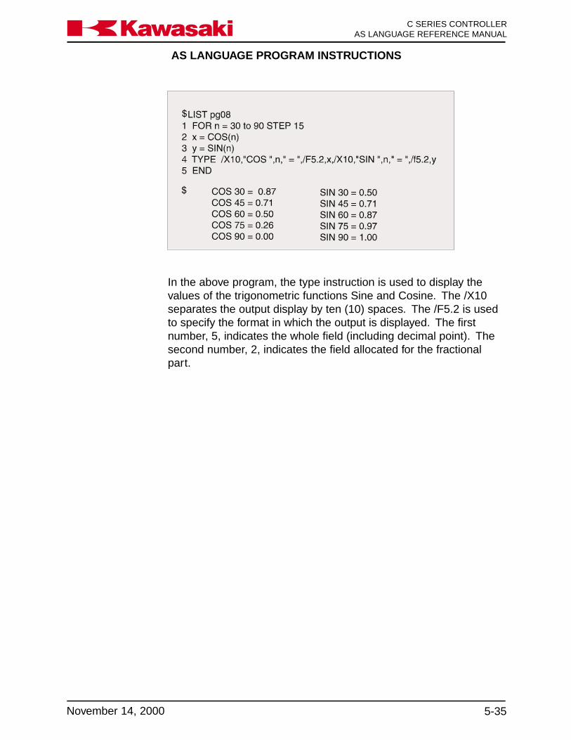
AS LANGUAGE PROGRAM INSTRUCTIONS
5-35November 14, 2000
Ka a aw s k C SERIES CONTROLLERAS LANGUAGE REFERENCE MANUAL
In the above program, the type instruction is used to display thevalues of the trigonometric functions Sine and Cosine. The /X10separates the output display by ten (10) spaces. The /F5.2 is usedto specify the format in which the output is displayed. The firstnumber, 5, indicates the whole field (including decimal point). Thesecond number, 2, indicates the field allocated for the fractionalpart.
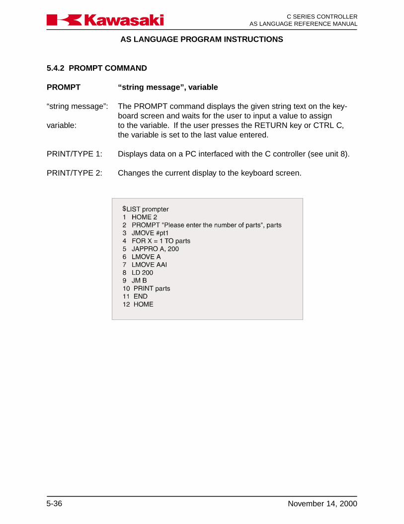
AS LANGUAGE PROGRAM INSTRUCTIONS
C SERIES CONTROLLERAS LANGUAGE REFERENCE MANUAL
5-36 November 14, 2000
Ka a aw s k
5.4.2 PROMPT COMMAND
PROMPT “string message”, variable
“string message”: The PROMPT command displays the given string text on the key-board screen and waits for the user to input a value to assign
variable: to the variable. If the user presses the RETURN key or CTRL C,the variable is set to the last value entered.
PRINT/TYPE 1: Displays data on a PC interfaced with the C controller (see unit 8).
PRINT/TYPE 2: Changes the current display to the keyboard screen.

AS LANGUAGE PROGRAM INSTRUCTIONS
5-37November 14, 2000
Ka a aw s k C SERIES CONTROLLERAS LANGUAGE REFERENCE MANUAL
In the program prompter the robot moves to the HOME 2 positionand displays the message “Please enter the number of parts”.Motion to point #pt1 does not begin until the user enters a value forthe variable parts. The FOR TO END loop is a structure that resultsin the repeated execution of steps 5 through 10. This block of stepsis repeated n times, where n is equal to the value entered for thevariable parts.
5.5 EXTERNAL OUTPUT SIGNAL CONTROL
SIGNAL Turns specified signals ON or OFF.PULSE Turns signal ON for a specified time.DYLSIG Turns signal ON after a specified time has elapsed.BITS Sets the states of a group of signals.RUNMASK Masks a group of signals. (These signals cannot remain ON after
execution stops.)RESET Turns OFF all external output signals.
5.5.1 SIGNAL, PULSE, AND DYLSIG COMMANDS
SIGNAL signal_number
Turns the specified external output signals or internal I/O signalsON or OFF.
signal_number: A real value expression used to determine external binary outputsignal numbers or internal I/O signal numbers. Positive values turnsignals ON. Negative values turn signals OFF. If the signal is zero,it is ignored and no signals are changed.
Signal numbers 1 to 256 are external binary output signals, andsignals from 2001 to 2256 are internal I/O signals. Binary inputsignals (1001 to 1256) cannot be specified. For external outputsignals, only the signals which are installed and configured asoutputs can be used. To check the current I/O signal configuration,use the IO command.

AS LANGUAGE PROGRAM INSTRUCTIONS
C SERIES CONTROLLERAS LANGUAGE REFERENCE MANUAL
5-38 November 14, 2000
Ka a aw s k
PULSE signal_number, time
Turns the specified signal ON for a specified period of time.
signal_number: Number of an external output signal or an internal signal.
time: Time in seconds for which the signal is kept ON. If omitted, it is setto 0.2 seconds.
DLYSIG signal_number, time
Turns ON/OFF the specified signal after a given time has elapsed.
signal_number: Number of an external output signal or an internal signal. Positivevalues indicate the signal is turned ON, and negative values indi-cate the signal is turned OFF. The signal number must be from 1 to32 or from 2001 to 2032.
time: Period of time (seconds).
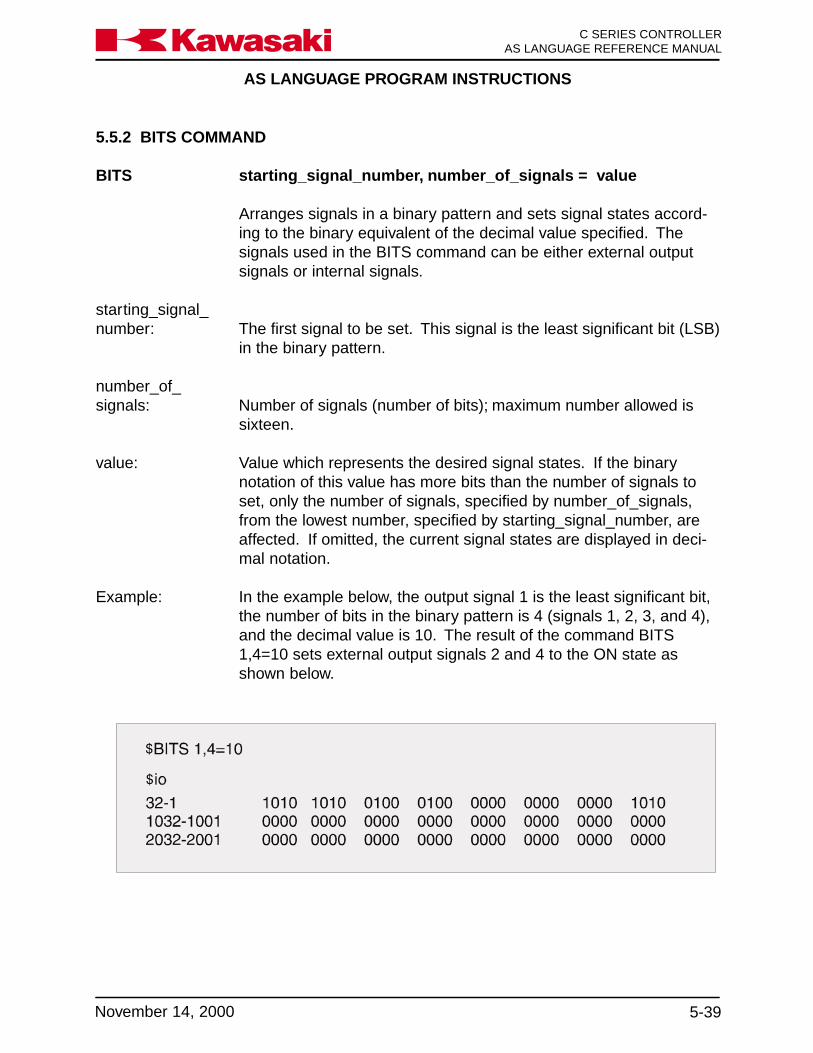
AS LANGUAGE PROGRAM INSTRUCTIONS
5-39November 14, 2000
Ka a aw s k C SERIES CONTROLLERAS LANGUAGE REFERENCE MANUAL
5.5.2 BITS COMMAND
BITS starting_signal_number, number_of_signals = value
Arranges signals in a binary pattern and sets signal states accord-ing to the binary equivalent of the decimal value specified. Thesignals used in the BITS command can be either external outputsignals or internal signals.
starting_signal_number: The first signal to be set. This signal is the least significant bit (LSB)
in the binary pattern.
number_of_signals: Number of signals (number of bits); maximum number allowed is
sixteen.
value: Value which represents the desired signal states. If the binarynotation of this value has more bits than the number of signals toset, only the number of signals, specified by number_of_signals,from the lowest number, specified by starting_signal_number, areaffected. If omitted, the current signal states are displayed in deci-mal notation.
Example: In the example below, the output signal 1 is the least significant bit,the number of bits in the binary pattern is 4 (signals 1, 2, 3, and 4),and the decimal value is 10. The result of the command BITS1,4=10 sets external output signals 2 and 4 to the ON state asshown below.

AS LANGUAGE PROGRAM INSTRUCTIONS
C SERIES CONTROLLERAS LANGUAGE REFERENCE MANUAL
5-40 November 14, 2000
Ka a aw s k
5.5.3 RESET AND RUNMASK COMMANDS
RESET Turns OFF all external output signals that are not dedicated.
RUNMASK starting_ signal_ number, number_ of _signals
Allows signals to be ON only while the program is executing. If thesignal is turned ON by a SIGNAL, PULSE, or DYLSIG instruction, itis turned OFF when execution is interrupted.
starting_signal_number: Number of the first signal in the group of signals to mask. A nega-
tive value indicates that the mask function is canceled. Theseunmasked signals are not turned OFF when execution is inter-rupted.
number_of_signals: Number of signals masked; default is one.
Whenever execution stops, the masked signals are turned OFFimmediately. Consider the case where execution is interrupted afterthe RUNMASK instruction is executed. If execution is resumed witha CONTINUE (DO or STEP) command, the signals are restoredonly while execution continues.
In the above example, output signals 1 and 3 turn ON when step 2is executed. When step 4 is executed, output signal 10 turns ON forthree seconds, then turns OFF. Output signal 15 turns ON fiveseconds after step 6 is executed. Output signals 1 through 15 aremonitored by the instruction in step 7, which de-energizes or resetsoutputs 1 through 15 when program execution is stopped.

AS LANGUAGE PROGRAM INSTRUCTIONS
5-41November 14, 2000
Ka a aw s k C SERIES CONTROLLERAS LANGUAGE REFERENCE MANUAL
5.6 DEFINITION OF VARIABLES
HERE Defines a location variable to be equal to the current robot location.POINT Defines a location variable.POINT/X Defines X component of a transformation variable.POINT/Y Defines Y component of a transformation variable.POINT/Z Defines Z component of a transformation variable.POINT/7 Defines seventh axis component of a transformation variable.POINT/OAT Defines OAT components of a transformation variable.DECOMPOSE Extracts component values from a location.TOOL Sets system internal transformation value of the tool.BASE Changes base coordinate system.LLIMIT Sets the lower limit of the robot motion.ULIMIT Sets the upper limit of the robot motion.TIMER Sets a timer.ON Turns system switches ON.OFF Turns system switches OFF.
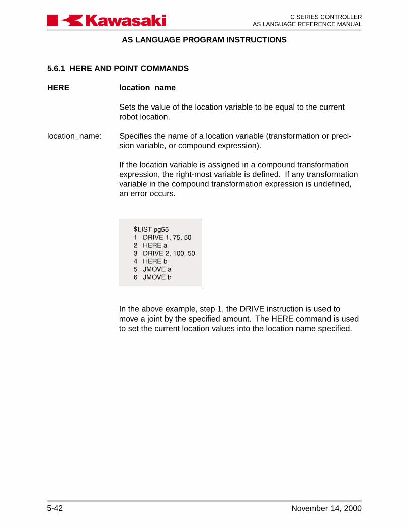
AS LANGUAGE PROGRAM INSTRUCTIONS
C SERIES CONTROLLERAS LANGUAGE REFERENCE MANUAL
5-42 November 14, 2000
Ka a aw s k
5.6.1 HERE AND POINT COMMANDS
HERE location_name
Sets the value of the location variable to be equal to the currentrobot location.
location_name: Specifies the name of a location variable (transformation or preci-sion variable, or compound expression).
If the location variable is assigned in a compound transformationexpression, the right-most variable is defined. If any transformationvariable in the compound transformation expression is undefined,an error occurs.
In the above example, step 1, the DRIVE instruction is used tomove a joint by the specified amount. The HERE command is usedto set the current location values into the location name specified.
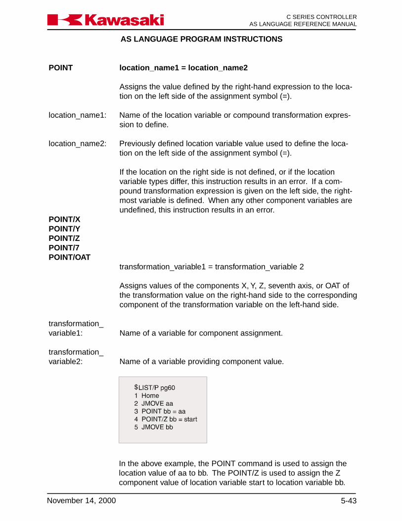
AS LANGUAGE PROGRAM INSTRUCTIONS
5-43November 14, 2000
Ka a aw s k C SERIES CONTROLLERAS LANGUAGE REFERENCE MANUAL
POINT location_name1 = location_name2
Assigns the value defined by the right-hand expression to the loca-tion on the left side of the assignment symbol (=).
location_name1: Name of the location variable or compound transformation expres-sion to define.
location_name2: Previously defined location variable value used to define the loca-tion on the left side of the assignment symbol (=).
If the location on the right side is not defined, or if the locationvariable types differ, this instruction results in an error. If a com-pound transformation expression is given on the left side, the right-most variable is defined. When any other component variables areundefined, this instruction results in an error.
POINT/XPOINT/YPOINT/ZPOINT/7POINT/OAT
transformation_variable1 = transformation_variable 2
Assigns values of the components X, Y, Z, seventh axis, or OAT ofthe transformation value on the right-hand side to the correspondingcomponent of the transformation variable on the left-hand side.
transformation_variable1: Name of a variable for component assignment.
transformation_variable2: Name of a variable providing component value.
In the above example, the POINT command is used to assign thelocation value of aa to bb. The POINT/Z is used to assign the Zcomponent value of location variable start to location variable bb.
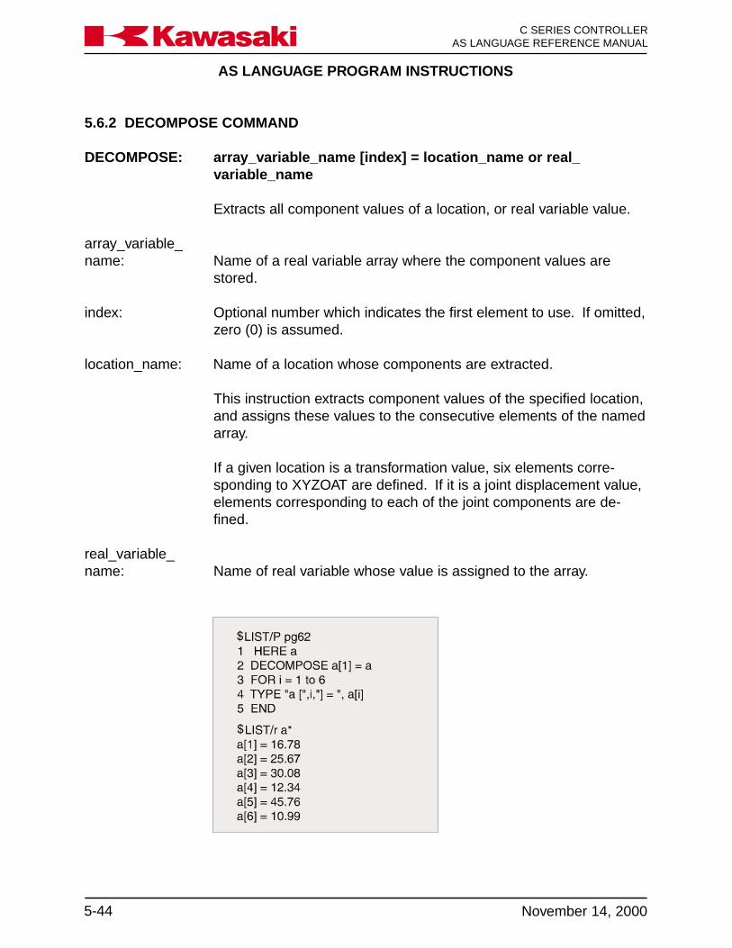
AS LANGUAGE PROGRAM INSTRUCTIONS
C SERIES CONTROLLERAS LANGUAGE REFERENCE MANUAL
5-44 November 14, 2000
Ka a aw s k
5.6.2 DECOMPOSE COMMAND
DECOMPOSE: array_variable_name [index] = location_name or real_variable_name
Extracts all component values of a location, or real variable value.
array_variable_name: Name of a real variable array where the component values are
stored.
index: Optional number which indicates the first element to use. If omitted,zero (0) is assumed.
location_name: Name of a location whose components are extracted.
This instruction extracts component values of the specified location,and assigns these values to the consecutive elements of the namedarray.
If a given location is a transformation value, six elements corre-sponding to XYZOAT are defined. If it is a joint displacement value,elements corresponding to each of the joint components are de-fined.
real_variable_name: Name of real variable whose value is assigned to the array.
AS LANGUAGE PROGRAM INSTRUCTIONS
5-45November 14, 2000
Ka a aw s k C SERIES CONTROLLERAS LANGUAGE REFERENCE MANUAL
In the example on the previous page, the current location of therobot is defined as a. The DECOMPOSE instruction extracts com-ponent values one through six of a. The program instructions be-tween the FOR and END statement are executed repeatedly, andthe TYPE instruction displays the component values of a individu-ally.
5.6.3 TOOL AND BASE COMMANDS
TOOL transformation_value
Sets the system’s internal transformation value indicating the posi-tion and direction of the tool tip, relative to the tool mounting flange.
If a NULL transformation value is given, the tool is set to be null tool(0,0,0,0,0,0).
This instruction causes a BREAK in the continuous path motion andthe value of the tool transformation is changed at the next location.
For further information on this instruction, refer to the description ofthe TOOL monitor command, section 4.5.2.
BASE transformation_value
Changes the robot base coordinate system by the given transforma-tion value.
If a NULL transformation value is given, the base coordinate systemis set to be NULL base (0,0,0,0,0,0).
This instruction causes a BREAK in the continuous path motion,and changes the base coordinate system at the next location.
For further information on this instruction, refer to the description ofthe BASE command, section 4.5.2.
5.6.4 LLIMIT AND ULIMIT COMMANDS
LLIMIT, ULIMIT precision_value (joint angle)
Sets the value (degrees) of the lower limit/upper limit of the motionrange of the robot. Changes to the limits of the robot affect allprograms in memory.

AS LANGUAGE PROGRAM INSTRUCTIONS
C SERIES CONTROLLERAS LANGUAGE REFERENCE MANUAL
5-46 November 14, 2000
Ka a aw s k
5.6.5 TIMER AND SWITCH COMMANDS
TIMER timer_number = time
Sets the time of the specified timer.
timer_number: Number of the timer to set. Ten timers are available, one through
ten.
time: Time (in seconds) which is allocated to the timer.
When the instruction is executed, the specified timer is set to havethe specified time. The value of the timer is obtained using theTIMER function.
Example: In this example the TIMER command is used to obtain a cycle timefor the program in seconds.

AS LANGUAGE PROGRAM INSTRUCTIONS
5-47November 14, 2000
Ka a aw s k C SERIES CONTROLLERAS LANGUAGE REFERENCE MANUAL
SWITCH_NAME ON
SWITCH_NAME OFF
Turns the specified system switches ON or OFF. The current settingof the system switch is displayed with the SWITCH command. Inthe example below, the CP and ARC switch is turned off.

AS LANGUAGE PROGRAM INSTRUCTIONS
C SERIES CONTROLLERAS LANGUAGE REFERENCE MANUAL
5-48 November 14, 2000
Ka a aw s k
5.7 CONTROL FLOW STRUCTURES
IF THEN ELSE Permits program instructions to be executed if the logical IF expres-sion is true.
WHILE DO Causes the repeated execution of a group of instructions while agiven expression is true.
DO UNTIL Provides a way to control the execution of a group of instructionsbased on a control expression.
FOR TO Results in the repeated execution of a block of instructions.
CASE OF Evaluates index variables and executes associated program instruc-tions.
Control flow structures are special types of program instructionsthat consist of more than one line of code to form a group or blockof steps. Depending on the structure used, these blocks can pro-vide sequence control, decision making, looping, and the ability toselect a set of actions from many possible sets. The followingsections discuss the five control flow structures available with theAS Language.
5.7.1 IF THEN ELSE COMMAND
IF THENELSEEND IF (logical expression) THEN
... instruction(s) to executewhen the condition is true
...ELSE (optional)...... instruction(s) to execute
when the condition is false...END... continue execution of program here
This block structure is an extension to the logical IF instruction.This block permits execution of more than one instruction if thelogical expression being tested is true. The logical IF statement

AS LANGUAGE PROGRAM INSTRUCTIONS
5-49November 14, 2000
Ka a aw s k C SERIES CONTROLLERAS LANGUAGE REFERENCE MANUAL
permits only a single statement to be given after the logical expres-sion. The block structure also permits an optional ELSE capabilityto the IF THEN ELSE block. It includes instructions to be executedwhenever the logical condition is false.
When the logical expression is true, the instructions following the IF(logical expression) THEN statement, and preceding the ELSEstatement are executed. Control of execution is then transferred tothe statement following the END statement. When the logical ex-pression is false, the instructions following the ELSE statement, andpreceding the END statement are executed. Control of execution isthen transferred to the step following the END.
Example:For example, a segment of the AS program shown below sets theprogram speed to 10 percent if the value of the variable n is greaterthan five. If the variable is less than five, the program speed is setto 20 percent.
21 IF n>5 THEN22 v=1023 ELSE24 v=2025 END26 SPEED v ALWAYS
The ELSE statement is optional. When this statement is omitted,and the logical expression is false, control of execution is trans-ferred to the step following the END statement. For example:
51 IF x>0 THEN52 pick = pick + x53 count = count + 154 END
This block adds x to the variable pick and increments the countercount by one, only if the value of x is positive.

AS LANGUAGE PROGRAM INSTRUCTIONS
C SERIES CONTROLLERAS LANGUAGE REFERENCE MANUAL
5-50 November 14, 2000
Ka a aw s k
5.7.2 WHILE DO COMMAND
WHILE DO END WHILE logical expression DO...... instruction(s) to execute while the condition is true...END... continue execution of program here
The WHILE DO block causes the repeated execution of a group ofinstructions while a given expression is true. If the expressionbecomes false, execution of the END statement is processed. Thegeneral form of this block structure is shown above.
If the logical expression is true, the instructions following the WHILEDO statement and preceding the END statement are executed.Control of execution returns to the WHILE DO statement and re-tests the logical expression. This flow of execution continues re-peatedly until the logical expression becomes false, or until anotherconditional statement inside the block causes a transfer out of theblock structure. When the logical expression is false (which in-cludes the first condition), control of execution resumes at the stepfollowing the END statement.
Example: The following example uses a WHILE structure to monitor a combi-nation of input signals to determine when a sequence of motionsshould stop. In this example, if the signal from either part feederbecomes zero (assumed to indicate the feeder is empty), then therepetitive motion of the robot stops and the program continues atstep 27.
23 WHILE SIG (feeder1, feeder2) DO24 CALL part125 CALL part226 END27 HOME
NOTE
If either feeder is empty when the WHILE structure isfirst encountered, then execution immediately skips tostep 27.

AS LANGUAGE PROGRAM INSTRUCTIONS
5-51November 14, 2000
Ka a aw s k C SERIES CONTROLLERAS LANGUAGE REFERENCE MANUAL
5.7.2.1 LOOP CONTROL VARIABLES
Loop control variables are often used with WHILE DO controlstructures. The loop control variable is one whose value is continu-ally tested in the logical expression. This variable must be initializedprior to entering the WHILE DO loop, for the loop to be executed thecorrect number of times. The value of the loop control variable mustbe updated within each loop execution. If the loop control variableis not updated, the logical expression may never become false andloop exit does not occur. Update of the loop control variable isusually the last executable instruction in the WHILE loop.
90 n=091 WHILE n<50 DO92 JMOVE weld93 n=n+194 END
The END statement is a non-executable statement. If control ofexecution is transferred to an instruction inside the block structure,the instructions are executed in a sequential manner, and the ENDstatement is ignored. Control of execution may be transferred to astatement outside the block structure at any time. The WHILE DOstatement cannot be the range statement in a DO loop, nor thestatement used in a logical IF.
5.7.3 DO UNTIL COMMAND
DOUNTIL DO
...
... statement(s) to execute
...UNTIL logical expression
The DO UNTIL structure provides a way to control the execution ofa group of instructions based on a control expression. The generalformat of this structure is shown above. When this structure isused, some action occurs within the group of enclosed instructionsthat changes the result of the logical expression from TRUE toFALSE. When FALSE, the structure is exited.
The DO UNTIL loop performs the same logic as the previous DOWHILE loop. The difference is, the DO UNTIL structure assuresinstructions in the body of the loop are executed at least once.

AS LANGUAGE PROGRAM INSTRUCTIONS
C SERIES CONTROLLERAS LANGUAGE REFERENCE MANUAL
5-52 November 14, 2000
Ka a aw s k
No instructions are needed between the DO and UNTIL statements.When there are no instructions, the UNTIL criterion is continuouslyevaluated (stays in the loop) until it is satisfied, then program execu-tion continues with the instructions following the UNTIL instruction.
Example: The following example uses a DO structure to control a task thatinvolves welding two parts on a carrier. The sequence assumesthat the binary signal line buffer.full changes to the ON state whenthe parts buffer becomes full. (The robot then performs a differentsequence of motions.)
50 DO51 CALL weldparta152 CALL weldparta253 UNTIL SIG (buffer.full)
5.7.4 FOR TO COMMAND
FOR TO STEPEND FOR loop_variable = start value TO end value
STEP step_value...... instruction(s) to execute...END... continue execution of program
The FOR END loop is a structure that results in the repeated execu-tion of a block of instructions. The general form of this control stru-cture is shown above.
In the FOR END structure, the user must establish a counter vari-able (loop variable), and specify the range of values (start value TOend value) the variable takes during execution of the loop. At thebeginning of each loop, the counter is assigned a new value. If thecounter is within the range of values specified (start value TO endvalue), the block of instructions is executed once. The looping endswhen the counter has gone through the entire range of values. Thefollowing are characteristics of the FOR TO STEP END structure:

AS LANGUAGE PROGRAM INSTRUCTIONS
5-53November 14, 2000
Ka a aw s k C SERIES CONTROLLERAS LANGUAGE REFERENCE MANUAL
The block of instructions is preceded by a FOR statement at the topof the structure and followed by an END statement at the bottom ofthe structure.
The FOR statement names the counter variable and specifies thebeginning and ending values of the counter. These two values areexpressed as constants (variables that receive values before thestart of the loop), or arithmetic expressions that compute a range ofvalues for the counter variable.
The optional STEP statement specifies the amount (step value) thecounter variable is increased or decreased after each loop. If itsvalue is a positive number, the value of the counter increases witheach execution. If the step value is negative, the counter de-creases. If the STEP statement is omitted, the default increment is+1.
The FOR END structure does not loop if the start value is less thanthe end value and the step value is negative, or the start value isgreater than the end value and the step value is positive.
Example: FOR i = 2 to 6 STEP 2DRAW 100, 10 * i + 7, 50HERE weld[i]END
In the above example, the robot moves 100 mm in X, a calculatedamount (10 * i + 7 mm) in the Y direction, and 50 mm in the Z direc-tion, and defines the location as weld[i].
The FOR statement in this example increments the value of “i” inincrements of two.
Example: i = 2, i = 4, i = 6.
AS LANGUAGE PROGRAM INSTRUCTIONS
C SERIES CONTROLLERAS LANGUAGE REFERENCE MANUAL
5-54 November 14, 2000
Ka a aw s k
5.7.5 CASE COMMAND
CASE OFVALUEANYEND CASE (index variable) OF
VALUE number1 ,......... :program instructions......VALUE number2,...........:program instructions......ANYprogram instructions......END
The CASE block structure selects a VALUE to match the indexvariable. This block structure provides capabilities similar to thoseof a GO TO statement. The general form of the CASE block isshown above.
The index variable is a real value expression used to select thematching VALUE and preform the program instructions contained inthe value. The CASE structure evaluates the index variable, andexamines the VALUE statements sequentially to find the sameVALUE as the index variable. After the instructions belonging to theselected VALUE statement are executed, control of execution re-sumes at the step immediately following the END statement (unlessa GO TO statement is encountered).
If there is no VALUE match between the index variable and theVALUE(S), the ANY statement is executed.
If there is not an ANY statement the program continues at the stepfollowing the END statement

AS LANGUAGE PROGRAM INSTRUCTIONS
5-55November 14, 2000
Ka a aw s k C SERIES CONTROLLERAS LANGUAGE REFERENCE MANUAL
Example: The example program displays different messages according to thevalue of the index variable x. If the value is negative, a messageindicating the value is negative is displayed, if the value is positive,one of the three different messages are selected using the CASEstructure. Three cases are: even numbers below eleven, oddnumbers below ten, and numbers greater than ten.
25 IF x<0 GOTO 1026 CASE x OF27 VALUE 0,2,4,6,8,10:28 PRINT “The number” ,x, “is EVEN”29 VALUE 1,3,5,7,9:30 PRINT “The number” ,x, “is ODD”31 ANY32 PRINT “The number” ,x, “is larger than 10”33 END34 STOP35 PRINT “Interrupting program because of negative value”36 STOP

AS LANGUAGE FUNCTIONS
6-1November 14, 2000
Ka a aw s k C SERIES CONTROLLERAS LANGUAGE REFERENCE MANUAL
6.0 FUNCTIONS .................................................................................................... 6-26.1 Real Value Functions ........................................................................................ 6-26.1.1 True and False Functions ................................................................................. 6-26.1.2 SIG and BITS Functions ................................................................................... 6-26.1.3 TIMER Function ............................................................................................... 6-46.1.4 DISTANCE and DX, DY, DZ Functions ............................................................. 6-56.1.5 ASC and LEN Functions .................................................................................. 6-66.1.6 INT, TASK, and AVE_TRANS Functions........................................................... 6-66.1.7 BASE and TOOL Functions .............................................................................. 6-76.1.8 ERROR Function .............................................................................................. 6-86.1.9 SWITCH Function ............................................................................................ 6-86.1.10 MAXVAL and MINVAL Functions ..................................................................... 6-86.2 Location Value Functions ................................................................................. 6-96.2.1 FRAME Function .............................................................................................. 6-96.2.2 TRANS and NULL Functions ......................................................................... 6-126.2.3 SHIFT Function .............................................................................................. 6-136.2.4 HERE and #HERE Functions ......................................................................... 6-146.2.5 #PPOINT Function ......................................................................................... 6-146.2.6 RX, RY, and RZ Functions .............................................................................. 6-146.2.7 DEST and #DEST Functions .......................................................................... 6-156.3 Arithmetic Functions ....................................................................................... 6-16
AS LANGUAGE FUNCTIONS
C SERIES CONTROLLERAS LANGUAGE REFERENCE MANUAL
6-2 November 14, 2000
Ka a aw s k
6.0 FUNCTIONS
A function is an operator that creates a value. For example, if the line x=SQRT 9 isexecuted in an AS Language program, the arithmetic function square root (SQRT)creates the value 3. The assignment instruction (=) stores the number 3 in the variablex. Functions are often combined with program instructions to create a value, however,some functions stand alone in a program.
6.1 REAL VALUE FUNCTIONS
TRUE, ON Returns the value -1.0 which represents TRUE (ON).FALSE, OFF Returns the value 0.0 which represents FALSE (OFF).SIG Returns the logical AND of the specified signal.BITS Returns the value corresponding to the bit pattern of the signals.TIMER Returns the current value of the timer.DISTANCE Returns the distance between two points.DX, DY, DZ Returns displacement component of transformation values.ASC Returns ASCII character value.LEN Returns string length.
6.1.1 TRUE AND FALSE FUNCTIONS
TRUE/ON Returns the value -1.0 which represents the logical value TRUE(ON). This function is useful to specify the logical condition TRUE.
FALSE/OFF Returns the value 0.0 which represents the logical value FALSE(OFF). This function is useful to specify the logical conditionFALSE.
6.1.2 SIG AND BITS FUNCTIONS
SIG (signal_number,signal_number)
Returns the logical AND of the specified binary signal states.
Calculates logical AND of all the specified binary signal states andreturns the resulting value. If all the specified signal states areTRUE, the SIG function returns TRUE -1. Otherwise, the SIGfunction returns FALSE 0.
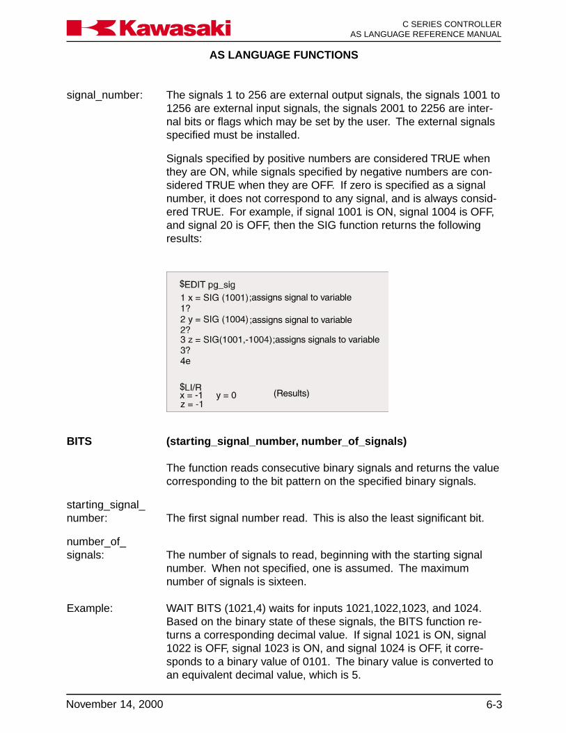
AS LANGUAGE FUNCTIONS
6-3November 14, 2000
Ka a aw s k C SERIES CONTROLLERAS LANGUAGE REFERENCE MANUAL
BITS (starting_signal_number, number_of_signals)
The function reads consecutive binary signals and returns the valuecorresponding to the bit pattern on the specified binary signals.
starting_signal_number: The first signal number read. This is also the least significant bit.
number_of_signals: The number of signals to read, beginning with the starting signal
number. When not specified, one is assumed. The maximumnumber of signals is sixteen.
Example: WAIT BITS (1021,4) waits for inputs 1021,1022,1023, and 1024.Based on the binary state of these signals, the BITS function re-turns a corresponding decimal value. If signal 1021 is ON, signal1022 is OFF, signal 1023 is ON, and signal 1024 is OFF, it corre-sponds to a binary value of 0101. The binary value is converted toan equivalent decimal value, which is 5.
signal_number: The signals 1 to 256 are external output signals, the signals 1001 to1256 are external input signals, the signals 2001 to 2256 are inter-nal bits or flags which may be set by the user. The external signalsspecified must be installed.
Signals specified by positive numbers are considered TRUE whenthey are ON, while signals specified by negative numbers are con-sidered TRUE when they are OFF. If zero is specified as a signalnumber, it does not correspond to any signal, and is always consid-ered TRUE. For example, if signal 1001 is ON, signal 1004 is OFF,and signal 20 is OFF, then the SIG function returns the followingresults:
AS LANGUAGE FUNCTIONS
C SERIES CONTROLLERAS LANGUAGE REFERENCE MANUAL
6-4 November 14, 2000
Ka a aw s k
6.1.3 TIMER FUNCTION
TIMER (timer_number)
Returns the current value (in seconds) of the specified timer.
timer_number: Represents the number of the timer to read. The number mustrange from 1 to 10 and be enclosed within parenthesis. Timernumber 0 is used for the system clock and tracks the time elapsedsince the system started.
The value returned indicates the elapsed time (in seconds) sincethe last execution of the TIMER instruction for the timer specified. Ifthe specified timer is not assigned a value by the TIMER instruction,it has the same value as TIMER 0.
Example: The TIMER instruction on line 1 is used to set TIMER (1) to 0 sec-onds, and the TIMER function used on line 7 is used to obtain thecycle time for the program.

AS LANGUAGE FUNCTIONS
6-5November 14, 2000
Ka a aw s k C SERIES CONTROLLERAS LANGUAGE REFERENCE MANUAL
6.1.4 DISTANCE AND DX, DY, DZ FUNCTIONS
DISTANCE (transformation_value, transformation_value)
Calculates the straight line distance between the two locations.Returns the distance of the two specified points in millimeters.
transformation_value,transformation_value: Specifies the two locations for distance calculation.
The order of the two points does not affect the result.
Example: x=DISTANCE (start, HOME) assigns the straight line distancebetween location variable start and the HOME position to variable x.
DX, DY, DZ (transformation_value)
Returns the displacement value (X,Y,Z) of the specified location.
transformation_value: Name of transformation location whose X,Y, or Z component is
required.
Example: The transformation location start has a transformation value of:
X Y Z O A T125 250 -50 135 50 75
x=DX (start) DX function returns x = 125.00y=DY (start) DY function returns y = 250.00z=DZ (start) DZ function returns z = -50.00
Component values may be assigned to real variables, for example,y=DX(aa) assigns the x component value of location variable aa toreal variable y.
These three components can also be obtained using the DECOM-POSE instruction. If the rotation components (O, A, T) are required,the DECOMPOSE instruction must be used.
AS LANGUAGE FUNCTIONS
C SERIES CONTROLLERAS LANGUAGE REFERENCE MANUAL
6-6 November 14, 2000
Ka a aw s k
6.1.5 ASC AND LEN FUNCTIONS
ASC (string, character_number)
Returns the ASCII value of the specified character in the givenstring as a real value.
string: Expression which contains the character whose ASCII value isrequired. If the string is a null string, -1 is returned.
character_number: The number which indicates the character whose ASCII value isrequired. When omitted, or when 0 or 1 is specified, the first char-acter of the string is selected.
Example: w = ASC (“sample”,2) assigns the ASCII value of character a to realvariable w.
LEN (string)
Returns the number of characters contained in the given string.
string: Represents either a constant, variable, or expression whose lengthis required.
Example: r = LEN (“sample”) assigns a value of 6 to real variable r.
6.1.6 INT, TASK, AND AVE_TRANS FUNCTIONS
INT (expression)
Is used to return the nearest integer value of the expression,rounded down from the left of the decimal point. For example:
x = INT(0.123) 0 is returned for xy = INT(10.8) 10 is returned for xw = INT(-5.76) -5 is returned for xt = INT(3.125E+2) 312 is returnedINT(cost+0.5) The value of cost, rounded to the
nearest integer, is returned.

AS LANGUAGE FUNCTIONS
6-7November 14, 2000
Ka a aw s k C SERIES CONTROLLERAS LANGUAGE REFERENCE MANUAL
TASK (task_number)
Returns the execution status of a PC program. With the two armoption, a 1 or a 2 is entered to represent the robot. PC programs 1-3 are represented by 1001, 1002, and 1003.
robot_number: TASK (1) represents robot program number 1 and TASK (2) repre-sents robot program number two (with the two arm option).
Example: rbsta1 = TASK (1), assigns the status of robot program number 1(pg1) to real variable rbsta1.
With the two arm option:robot program 1 (used for arm 1) is named pg1.robot program 2 (used for arm 2) is named pg2.pc1 is used for variables.pc2 is used for peripheral equipment control.pc3 is used for variables.
task_number: TASK (1001) represent PC program 1.
Example: pcstat1 = TASK (1001), assigns the status of PC program 1 to thereal variable pcstat1.
No execution, returns 0Program executing, returns 1Program in HOLD, returns 2Program waiting for stepper, returns 3
AVE_TRANS (transformation 1, transformation 2)
The AVE_TRANS function returns the average X, Y, and Z compo-nent location of the two specified locations.
6.1.7 BASE AND TOOL FUNCTIONS
BASE Returns the location components of the defined BASE.
TOOL Returns the location components of the defined TOOL.

AS LANGUAGE FUNCTIONS
C SERIES CONTROLLERAS LANGUAGE REFERENCE MANUAL
6-8 November 14, 2000
Ka a aw s k
6.1.8 ERROR FUNCTION
ERRORReturns the error code number and message generated. For ex-ample, the command
TYPE $ERROR(ERROR)
types the error code number and message currently generated.
6.1.9 SWITCH FUNCTION
SWITCH (switch name)
Is used to return a -1.0 (ON) or 0.0 (OFF) value of the identifiedswitch.
Example: d = SWITCH(CP) If the CP switch is ON, a value of -1.0is returned as the value of “d”. If theCP switch is OFF, a value of 0.0 isreturned as the value of “d”.
6.1.10 MAXVAL AND MINVAL FUNCTIONS
MAXVAL (real variable 1, real variable 2, ... etc.)
returns the highest value of the identified real variables.
Example: if a=10, b=15, and c=20, the command
m = MAXVAL (a,b,c)
assigns a value of 20 to the real variable “m”.
MINVAL (real variable 1, real variable 2, ... etc.)
Returns the lowest value of the identified real variables.
Example: if a=10, b=15, and c=20, the command
m = MINVAL (a,b,c)
assigns a value of 10 to the real variable “m”.

AS LANGUAGE FUNCTIONS
6-9November 14, 2000
Ka a aw s k C SERIES CONTROLLERAS LANGUAGE REFERENCE MANUAL
6.2 LOCATION VALUE FUNCTIONS
FRAME Returns the transformation value which represents the relativecoordinate system.
TRANS Returns the transformation value composed of the given compo-nents.
NULL Returns a null transformation value.SHIFT Returns the transformation value generated by shifting the original
location.HERE Returns the current transformation location of the tool center point.#HERE Returns the current precision location in joint angles of the robot.#PPOINT Returns the precision value composed from the given components.RX, RY, RZ Returns the transformation value which represents a rotation.DEST Returns the destination location as a transformation value.#DEST Returns the destination location as a joint displacement value.Arithmetic Arithmetic functions and formats.Functions
6.2.1 FRAME FUNCTION
FRAME (location1, location2, location3, location4)
Returns the transformation values that represent the relative coordi-nate system.
location1,location2: Transformation values used to determine the direction of the X-axis
of the relative coordinate system. The direction of the X-axis isdefined parallel to the line between location1 and location2.
location3: Transformation value used to determine the direction of the Y-axis ofthe relative coordinate system. The direction of Y-axis is definedand the X-Y plane contains location1, location2 and location3.
location4: Transformation value that is the origin of the relative coordinatesystem.
Locations used within the FRAME must be relative to the coordinatesystem using compound expressions. When the coordinate systemrequires modification, only the reference location needs to be rede-fined with the FRAME function (Figure 6-1).
The FRAME function is used when the orientation of the task is notparallel or perpendicular to the robot base coordinate system.
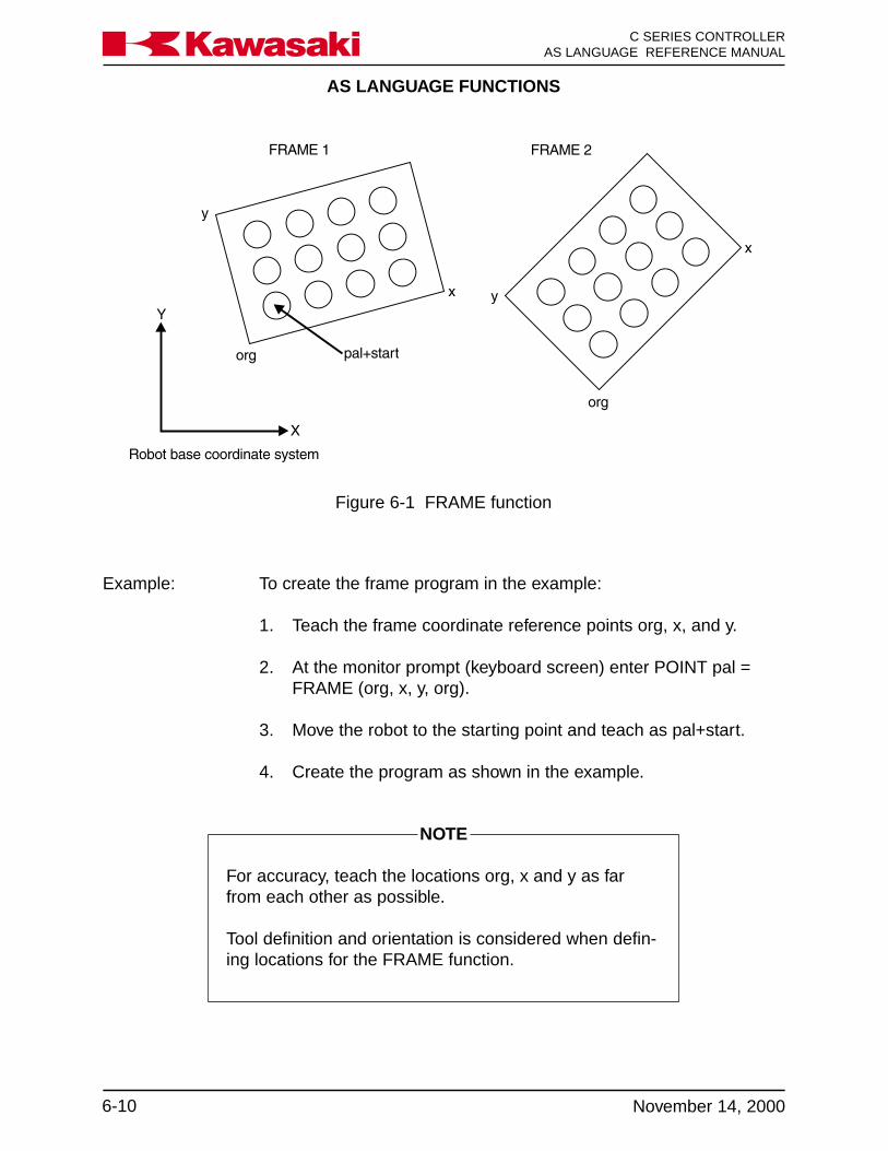
AS LANGUAGE FUNCTIONS
C SERIES CONTROLLERAS LANGUAGE REFERENCE MANUAL
6-10 November 14, 2000
Ka a aw s k
Figure 6-1 FRAME function
Example: To create the frame program in the example:
1. Teach the frame coordinate reference points org, x, and y.
2. At the monitor prompt (keyboard screen) enter POINT pal =FRAME (org, x, y, org).
3. Move the robot to the starting point and teach as pal+start.
4. Create the program as shown in the example.
NOTE
For accuracy, teach the locations org, x and y as farfrom each other as possible.
Tool definition and orientation is considered when defin-ing locations for the FRAME function.
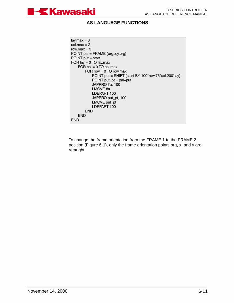
AS LANGUAGE FUNCTIONS
6-11November 14, 2000
Ka a aw s k C SERIES CONTROLLERAS LANGUAGE REFERENCE MANUAL
To change the frame orientation from the FRAME 1 to the FRAME 2position (Figure 6-1), only the frame orientation points org, x, and y areretaught.

AS LANGUAGE FUNCTIONS
C SERIES CONTROLLERAS LANGUAGE REFERENCE MANUAL
6-12 November 14, 2000
Ka a aw s k
6.2.2 TRANS AND NULL FUNCTIONS
TRANS (X_component, Y_component, Z_component, O_component,A_component, T_component)
Returns the transformation value consisting of the displacementcomponents (X,Y, Z) and the rotation components (O, A, T). Thetransformation value is calculated from the assigned componentvalues. The obtained transformation value is used in defining loca-tion transformations, motion requirements, or in compound transfor-mation expressions.
X, Y, Z_Component: Defines the displacement of X, Y, Z respectively.
O, A, T_Component: Defines the rotation components of O, A, T respectively.
The value returned is assigned to a real variable and is used tomodify the base coordinates.
Example: POINT totaloffset = TRANS (offsetx,offsetty,offsetz) BASEtotaloffset
NULL Returns a null transformation value of which all components arezero.
The null transformation value represents a location of which alldisplacement components are zero (X=Y=Z=0), and all rotationcomponents are zero (O=A=T=0). The null transformation is conve-nient for setting a coordinate system back to its original value whenrepetitive changes are required.

AS LANGUAGE FUNCTIONS
6-13November 14, 2000
Ka a aw s k C SERIES CONTROLLERAS LANGUAGE REFERENCE MANUAL
6.2.3 SHIFT FUNCTION
SHIFT (transformation_location BY X_shift, Y_shift, Z_shift)
Returns the transformation value representing the shifted position ofthe specified transformation value.
transformation_location: Transformation location name whose value is changed.
X_shiftY_shiftZ_shift: Represents the value added to the respective position components
of the specified transformation value. Values added are positive ornegative.
The transformation value returned by this function has X, Y, Z posi-tion components with respective shift values added.
The rotation components of the specified transformation valueremain unchanged. If any shift amount is omitted, zero is assumed.
The following example program is a palletizing routine using theSHIFT function.
Example: POINT put = startFOR col = 0 TO 5
FOR row = 0 TO 10POINT put = SHIFT(start BY 100*row, 75*col, 0)JAPPRO #a, 100LMOVE #aLDEPART 100JAPPRO put, 100LMOVE putLDEPART 100
ENDEND
In the example the “start” location is assigned to the location “put”.The two FOR TO END control flow structures are nested to fill onerow before shifting to fill the next row. X_shift (row) is 100 mm,Y_shift (col) is 75 mm, and Z_shift is 0 mm.
Six rows per column and eleven columns are filled to complete thenested loops.

AS LANGUAGE FUNCTIONS
C SERIES CONTROLLERAS LANGUAGE REFERENCE MANUAL
6-14 November 14, 2000
Ka a aw s k
6.2.4 HERE AND #HERE FUNCTIONS
HEREThe HERE function is used to return the current transformationlocation of the tool center point. In the following example, the HEREfunction is used to calculate the distance from the robot’s currentposition to a previously defined transformation location named“spot”.
dist = DISTANCE (HERE, spot)
The value (distance in mm) assigned to the real variable dist can beutilized by the programmer in a number different ways, including:printing the calculation, using the information in a mathematicalexpression, or utilizing the calculation in a logical evaluation.
#HERE The #HERE function is used to return the current precision locationin joint angles of the robot. The #HERE function can be used toassign precision locations to previously undefined precision loca-tions.
6.2.5 #PPOINT FUNCTION
#PPOINT (jt1, jt2, jt3, jt4, jt5, jt6)
The #PPOINT function returns the precision location which consistsof the given components. The precision component of each joint ofthe robot is represented as jt1, jt2, jt3, jt4, jt5, and jt6. If a value fora specified joint is omitted, it is set to zero (0). The #PPOINT com-mand can be used to position the robot to specific joint angles or tomanipulate the joint angles of previously defined precision points.
6.2.6 RX, RY, AND RZ FUNCTIONS
RX (angle)
RY (angle)
RZ (angle)
The RX, RY, and RZ functions return transformation values thatrepresent rotation around the specified axis of the base coordinatesystem.
AS LANGUAGE FUNCTIONS
6-15November 14, 2000
Ka a aw s k C SERIES CONTROLLERAS LANGUAGE REFERENCE MANUAL
Example: POINT crnr = RX(45)
Assigns a value 45 degrees of rotation about the X-axis of the basecoordinate system to the transformation location crnr.
6.2.7 DEST AND #DEST FUNCTIONS
DEST Returns the value of transformation location, which is the planneddestination location of the current robot motion.
The location where the robot stops, and the location the DESTfunction returns are not always identical. If robot motion is inter-rupted for some reason (the HOLD/RUN switch is turned to theHOLD position) the robot stops immediately. The DEST functionreturns the robot to the original destination location.
#DEST Returns the value of the precision location, which is the planneddestination location of the current robot motion.
The location where the robot actually stops and the location that the#DEST function returns to are not always identical. If the robotmotion has been interrupted for some reason (for example, whenthe HOLD/RUN switch on the panel is turned to the HOLD position),the robot stops immediately. The #DEST function returns the robotto the original destination location.
The DEST function is useful to continue the motion that was inter-rupted because of an ONI signal_number CALL program instruc-tion. By inserting the following steps in an interrupt subroutine, theinterrupted motion can be resumed.
POINT new = HERE ;Stores current location in the variable new.
POINT old = DEST ;Stores the destination location in the variableold.
JDEPART 50 ;Backs the tool away by 50 mm.
JMOVE old ;Starts motion to the planned destination.

AS LANGUAGE FUNCTIONS
C SERIES CONTROLLERAS LANGUAGE REFERENCE MANUAL
6-16 November 14, 2000
Ka a aw s k
6.3 ARITHMETIC FUNCTIONS
ABS: Returns the absolute value of a numerical expression.SQRT: Returns the square root of a numerical expression.PI: Returns the constant π.SIN: Returns the sine value.COS: Returns the cosine value.ATAN2: Returns the arctangent value.RANDOM: Returns a random number.
COMMAND FUNCTION FORMAT
ABS Returns the absolute value of a numerical value. ABS (value)SQRT Returns the square root of a numerical value. SQRT (value)PI Returns the ratio of the circumference of a circle PI
to its diameter; (3.1415…).SIN Returns the sine (sin) of a given angle. SIN (value)COS Returns the cosine (cos) of a given angle. COS (value)ATAN2 Returns the value of an angle (in degrees) ATAN2 (v1,v2)
whose tangent (tan) equals v1/v2.RANDOM Returns a random number from 0.0 to 1.0. RANDOM

CREATING AND EXECUTING PROGRAMS
7-1November 14, 2000
Ka a aw s k C SERIES CONTROLLERAS LANGUAGE REFERENCE MANUAL
7.0 CREATING AND EXECUTING PROGRAMS ................................................ 7-27.1 Types of AS Language Programs .................................................................. 7-27.1.1 Robot Control Programs ................................................................................ 7-27.1.2 PC Program (Process Control) ...................................................................... 7-27.1.3 SLOGIC Programs ......................................................................................... 7-27.2 Program Step Format ................................................................................... 7-37.3 Program Execution ........................................................................................ 7-47.3.1 Executing Robot Control Programs................................................................ 7-47.3.1.1 Stopping Robot Control Programs .................................................................. 7-57.4 Executing PC Programs ................................................................................. 7-57.5 Flowcharting .................................................................................................. 7-67.6 Compound Transformations and Tool Dimensions ....................................... 7-107.7 Sample Programs ........................................................................................ 7-13
CREATING AND EXECUTING PROGRAMS
C SERIES CONTROLLERAS LANGUAGE REFERENCE MANUAL
7-2 November 14, 2000
Ka a aw s k
7.0 CREATING AND EXECUTING PROGRAMS
An AS Language program is a collection of instructions used to direct the system tomove the robot, interface with other automation devices, evaluate variables, performmathematical calculations, execute logic instructions, and set external signals.
AS Language provides programmers the options and flexibility to program for uniqueapplications and requirements.
7.1 TYPES OF AS LANGUAGE PROGRAMS
7.1.1 ROBOT CONTROL PROGRAMS
A robot control program is a program which results in the direct movement of the robot.In the robot control program, all program instructions including robot motion instructionsare used.
7.1.2 PC PROGRAM (PROCESS CONTROL)
A PC program is a program which can be executed simultaneously with a robot controlprogram. A PC program is used to monitor or to control external devices through exter-nal I/O signals. PC programs can evaluate variables, perform mathematical calcula-tions, execute logic instructions, and set external or internal signals.
Unlike robot control programs, PC program instructions cannot cause robot motion. Theonly exception to this requirement for PC programs is the BRAKE instruction.
The BASE and TOOL instructions are not available for PC programs.
PC programs can be used to display messages on the terminal by means of the PRINTinstruction.
All internal and external I/O signals can be used in PC programs.
7.1.3 SLOGIC PROGRAMS
SLOGIC programs are used to provide logic instructions for remote I/O or ControlNetcommunication. SLOGIC programs execute from the optional 1FS board and provideinstructions for signal mapping, timers and counters similar to ladder logic programs.
SLOGIC programs are created on the 1GA board and downloaded to the 1FS board.

CREATING AND EXECUTING PROGRAMS
7-3November 14, 2000
Ka a aw s k C SERIES CONTROLLERAS LANGUAGE REFERENCE MANUAL
7.2 PROGRAM STEP FORMAT
Each step of an AS Language program uses the following format:
step number label program instruction; comment
1. Step number:
A step number is assigned to each line of a program. Steps are numbered con-secutively beginning with 1. Step numbers are automatically adjusted wheneverlines are inserted or deleted.
The only step number that can be blank (contain no information) is the step insertedafter the last step of the program.
2. Label:
Step numbers cannot be used as branch destinations with the program instructionGOTO.
Labels are used for identifying specific locations within a program for the purpose ofbranching to other parts of a program.
A label can be either an integer from 1 to 9999 or a character string up to 15 char-acters. Labels are inserted at the beginning of a program line.
3. Comment:
A semicolon (;) indicates that all of the information to the right of the semicolon is acomment.
Comments are not processed as program instructions when the program is ex-ecuted. Comments are used by programmers to help explain the contents of theprogram.
Comment lines with no label and no instruction can be created for improved pro-gram readability.

CREATING AND EXECUTING PROGRAMS
C SERIES CONTROLLERAS LANGUAGE REFERENCE MANUAL
7-4 November 14, 2000
Ka a aw s k
7.3.1 EXECUTING ROBOT CONTROL PROGRAMS
To execute a robot control program, select the desired program.
If the program to execute is already selected, the monitor command EXECUTE can beused. This runs the program one time and a message is displayed indicating the pro-gram was completed.
The EXECUTE command can be used with the optional argument of a program name torun a program not on the stack.
The number of times a program is to execute is entered after the program name. Tospecify the program to run continuously a -1 is entered.
The PRIME command, in conjunction with the CYCLE START switch, can be used whenexecuting programs. The PRIME command is used to specify the step of the programwhere execution starts, if no number is specified with the PRIME command, programexecution starts with the first step of the program.
When a program is run for the first time or for debugging a program, it is a good idea toconfirm each program line by line using the STEP command or the CHECK key on themulti function panel.
NOTE
Many operators utilize a “mainline” program to select allrobot control programs. While not a necessity, mainlineprograms are routinely named pg00. If your robot is in-tegrated into a system that is designed to operate with amainline program, it is important that the mainline pro-gram is selected to start production. If an individualprogram is selected and run independent of the main-line program, the required operations of the mainlineprogram will not be processed.
7.3 PROGRAM EXECUTION
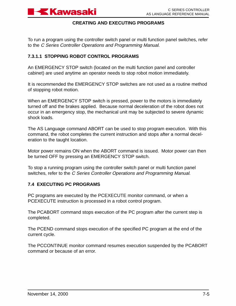
CREATING AND EXECUTING PROGRAMS
7-5November 14, 2000
Ka a aw s k C SERIES CONTROLLERAS LANGUAGE REFERENCE MANUAL
To run a program using the controller switch panel or multi function panel switches, referto the C Series Controller Operations and Programming Manual.
7.3.1.1 STOPPING ROBOT CONTROL PROGRAMS
An EMERGENCY STOP switch (located on the multi function panel and controllercabinet) are used anytime an operator needs to stop robot motion immediately.
It is recommended the EMERGENCY STOP switches are not used as a routine methodof stopping robot motion.
When an EMERGENCY STOP switch is pressed, power to the motors is immediatelyturned off and the brakes applied. Because normal deceleration of the robot does notoccur in an emergency stop, the mechanical unit may be subjected to severe dynamicshock loads.
The AS Language command ABORT can be used to stop program execution. With thiscommand, the robot completes the current instruction and stops after a normal decel-eration to the taught location.
Motor power remains ON when the ABORT command is issued. Motor power can thenbe turned OFF by pressing an EMERGENCY STOP switch.
To stop a running program using the controller switch panel or multi function panelswitches, refer to the C Series Controller Operations and Programming Manual.
7.4 EXECUTING PC PROGRAMS
PC programs are executed by the PCEXECUTE monitor command, or when aPCEXECUTE instruction is processed in a robot control program.
The PCABORT command stops execution of the PC program after the current step iscompleted.
The PCEND command stops execution of the specified PC program at the end of thecurrent cycle.
The PCCONTINUE monitor command resumes execution suspended by the PCABORTcommand or because of an error.

CREATING AND EXECUTING PROGRAMS
C SERIES CONTROLLERAS LANGUAGE REFERENCE MANUAL
7-6 November 14, 2000
Ka a aw s k
7.5 FLOWCHARTING
The procedure for writing complicated AS Language programs often begins with creat-ing a flowchart to identify the major elements of the process.
AS language programs are then written to meet the objectives identified in the flowchart.
Figure 7-1 shows an example of a working flowchart.
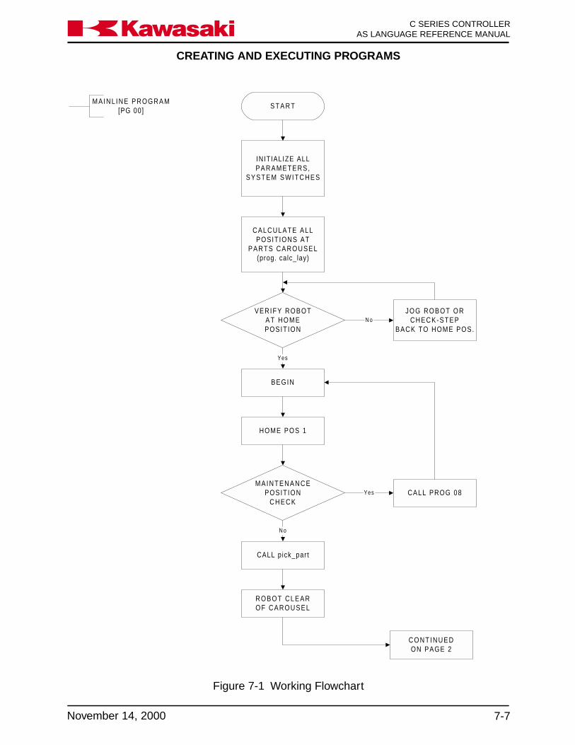
CREATING AND EXECUTING PROGRAMS
7-7November 14, 2000
Ka a aw s k C SERIES CONTROLLERAS LANGUAGE REFERENCE MANUAL
S T A R T
INITIALIZE ALLPARAMETERS,
S Y S T E M S W I T C H E S
VERIFY ROBOTA T H O M EPOSIT ION
BEGIN
J O G R O B O T O RCHECK-STEP
BACK TO HOME POS.
HOME POS 1
M A I N T E N A N C EPOSIT ION
C H E C KCALL PROG 08
CALL pick_part
C O N T I N U E DON PAGE 2
MAINL INE PROGRAM[PG 00]
CALCULATE ALLPOSIT IONS AT
PARTS CAROUSEL(prog. calc_lay)
Yes
N o
N o
Yes
R O B O T C L E A ROF CAROUSEL
Figure 7-1 Working Flowchart

CREATING AND EXECUTING PROGRAMS
C SERIES CONTROLLERAS LANGUAGE REFERENCE MANUAL
7-8 November 14, 2000
Ka a aw s k
FROM PAGE 1
NO PART COUNT>3
MAINL INE PROGRAM(pg 00 cont'd)
RESET NO PARTSC O U N T E R
RESET INDEX(layer counter)
INDEX>INDEX_MAX
ROTATE CAROUSEL
Yes
No
GO TO BEGIN
ROTATE CAROUSEL
Yes
No
RESET INDEX(layer counter)
HOME POS 1
CALL load_press
DISPLAY ROBOTCYCLE TIME
TO PDU
GO TO BEGIN
Figure 7-1 Working Flowchart (continued)

CREATING AND EXECUTING PROGRAMS
7-9November 14, 2000
Ka a aw s k C SERIES CONTROLLERAS LANGUAGE REFERENCE MANUAL
P R O G R A Mload_press
S T A R T
J M O V E#to_press_1
S W A I Tokay.to. load.press
R E S E Tclear.of.press
L M O V E#to_press_2
L M O V E#to_press_3
L M O V E#abv_ld_press
L M O V E#at_ ld_press
O P E N G R I P P E R
TWAIT 0 .25 SEC
L M O V E#outs_ ld_press
L M O V E#bel_ ld_press
P U L S Epart loaded signal
L M O V E#to_press_3
J M O V E#to_press_1
S E Tclear.of.press
S E Trobot cycle complete
H O M E
Figure 7-1 Working Flowchart (continued)
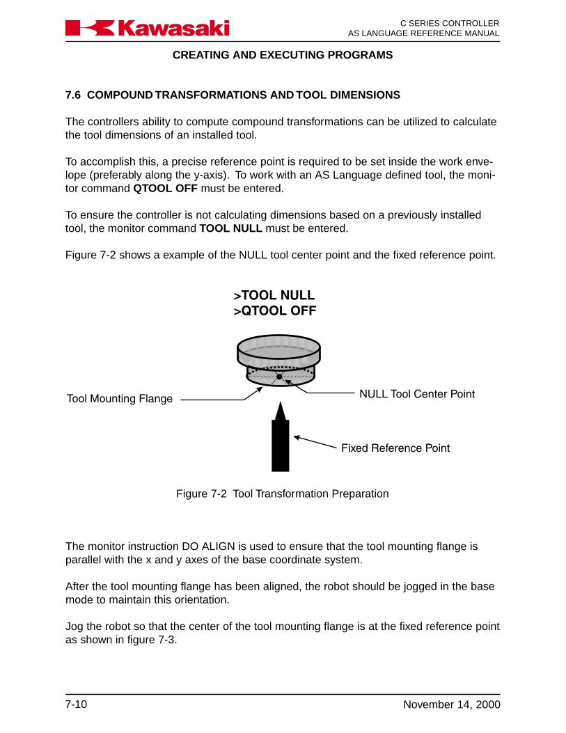
CREATING AND EXECUTING PROGRAMS
C SERIES CONTROLLERAS LANGUAGE REFERENCE MANUAL
7-10 November 14, 2000
Ka a aw s k
7.6 COMPOUND TRANSFORMATIONS AND TOOL DIMENSIONS
The controllers ability to compute compound transformations can be utilized to calculatethe tool dimensions of an installed tool.
To accomplish this, a precise reference point is required to be set inside the work enve-lope (preferably along the y-axis). To work with an AS Language defined tool, the moni-tor command QTOOL OFF must be entered.
To ensure the controller is not calculating dimensions based on a previously installedtool, the monitor command TOOL NULL must be entered.
Figure 7-2 shows a example of the NULL tool center point and the fixed reference point.
Figure 7-2 Tool Transformation Preparation
The monitor instruction DO ALIGN is used to ensure that the tool mounting flange isparallel with the x and y axes of the base coordinate system.
After the tool mounting flange has been aligned, the robot should be jogged in the basemode to maintain this orientation.
Jog the robot so that the center of the tool mounting flange is at the fixed reference pointas shown in figure 7-3.

CREATING AND EXECUTING PROGRAMS
7-11November 14, 2000
Ka a aw s k C SERIES CONTROLLERAS LANGUAGE REFERENCE MANUAL
Figure 7-3 Defining the Location a
Jog the robot away from the fixed reference point and install the tool to dimension.
After the tool is installed, jog the robot so the new tool center point is at the fixed refer-ence point.
The tool must be oriented so the z tool coordinate axis is perpendicular to the basecoordinate x and y axes.
The monitor command HERE a+b is entered to define and record the compound trans-formation location b (Figure 7-4).

CREATING AND EXECUTING PROGRAMS
C SERIES CONTROLLERAS LANGUAGE REFERENCE MANUAL
7-12 November 14, 2000
Ka a aw s k
Figure 7-4 Defining the Compound Transformation a+b
The monitor command POINT t= -b is entered to assign the inverse of the compoundtransformation b to the variable t.
The inverse of b is used because the compound transformation b is the location of theNULL tool center point relative to the fixed reference point.
The monitor command TOOL t is entered to assign the value of variable t to an ASLanguage tool.
To confirm the new tool dimensions are recorded properly, jog the robot away from thefixed reference point.
Select the jogging TOOL mode and jog the robot using the rx, ry, and rz keys. The toolcenter point remains fixed while the robot arm rotates about that point.
Ensure the path from the robot’s current position to the fixed reference is clear. Set therepeat condition speed to 10%. Place the robot in the repeat mode and enter the moni-tor command DO JM a, the tool center point travels to the fixed reference point.
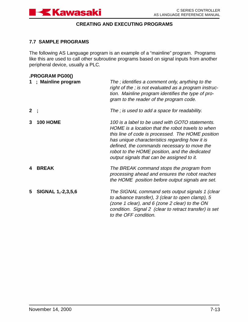
CREATING AND EXECUTING PROGRAMS
7-13November 14, 2000
Ka a aw s k C SERIES CONTROLLERAS LANGUAGE REFERENCE MANUAL
7.7 SAMPLE PROGRAMS
The following AS Language program is an example of a “mainline” program. Programslike this are used to call other subroutine programs based on signal inputs from anotherperipheral device, usually a PLC.
.PROGRAM PG00()1 ; Mainline program The ; identifies a comment only, anything to the
right of the ; is not evaluated as a program instruc-tion. Mainline program identifies the type of pro-gram to the reader of the program code.
2 ; The ; is used to add a space for readability.
3 100 HOME 100 is a label to be used with GOTO statements.HOME is a location that the robot travels to whenthis line of code is processed. The HOME positionhas unique characteristics regarding how it isdefined, the commands necessary to move therobot to the HOME position, and the dedicatedoutput signals that can be assigned to it.
4 BREAK The BREAK command stops the program fromprocessing ahead and ensures the robot reachesthe HOME position before output signals are set.
5 SIGNAL 1,-2,3,5,6 The SIGNAL command sets output signals 1 (clearto advance transfer), 3 (clear to open clamp), 5(zone 1 clear), and 6 (zone 2 clear) to the ONcondition. Signal 2 (clear to retract transfer) is setto the OFF condition.

CREATING AND EXECUTING PROGRAMS
C SERIES CONTROLLERAS LANGUAGE REFERENCE MANUAL
7-14 November 14, 2000
Ka a aw s k
6 ; The ; is used to add a space for readability.
7 WAIT BITS (1021,4) The WAIT command causes the program to sus-pend execution until the specified condition (BITS1021,4) is satisfied. The BITS command is used tospecify that 4 signals be evaluated for their binaryvalue, the first signal is 1021 (binary value of 1)the fourth signal is 1024 (binary value of 8), if anycombination of these signals are present, theprogram continues processing.
8 pg = BITS (1021,4) In this line of code, the binary value of signals1021 through 1024 (BITS (1021,4)) are assigned(=) to the real variable pg.
9 SIGNAL -3 The SIGNAL command is used to set outputsignal 3 (clear to unclamp) to the off condition.
10 CASE pg OF The CASE pg OF command is a control flowstructure that evaluates the real variable pg. If thevalue of pg matches the VALUE statement, theprogram instructions following the instruction areprocessed. If none of the VALUE statementsmatch the value of the variable pg, the programprocesses the first instruction after the END state-ment identifying the last step of the control flowstructure. As long as the value of pg matches aVALUE statement within the control flow structurethe program continues to process inside the struc-ture.
11 VALUE 8: In this line of code, if the VALUE of pg is 8, thenext line of the program is processed. If the valueof pg is not 8, then the program scans past thisline of code and continue to evaluate the VALUESfor a match with pg.
12 CALL pg8 If the program reaches this line of code, the in-struction CALL pg8 is executed. The CALL com-mand causes the program to execute the specifiedsubroutine, in this example, pg8.

CREATING AND EXECUTING PROGRAMS
7-15November 14, 2000
Ka a aw s k C SERIES CONTROLLERAS LANGUAGE REFERENCE MANUAL
13 VALUE 10: In this line of code, if the VALUE of pg is 10, thenext line of the program is processed. If the valueof pg is not 10, then the program scans past thisline of code and continues to evaluate the VALUESfor a match with pg.
14 CALL pg10 If the program reaches this line of code, the in-struction CALL pg10 is executed. The CALLcommand causes the program to execute thespecified subroutine, in this example, pg10.
15 END The END command identifies the end of the con-trol flow structure, CASE pg OF....VALUE xxx. Ifthe value of the specified variable is not matchedwithin the control flow structure the program pro-ceeds to process the first instruction after the ENDstatement.
16 ; The ; is used to add a space for readability.
17 IF NOT SIG (1001) GOTO 100 In this line of code, the signal state of input signal1001 (Signal 1001 move to pounce) is evaluatedfor an off or on condition. If input signal 1001signal is on, the next program instruction is pro-cessed. If input signal 1001 is off, the GOTO 100section of the instruction is processed and theprogram searches for the label 100 and continuesprocessing beginning with that instruction.
18 pg = BITS (1021,4) In this line of code, the binary value of signals1021 through 1024 (BITS (1021,4)) are assigned(=) to the real variable pg.
CREATING AND EXECUTING PROGRAMS
C SERIES CONTROLLERAS LANGUAGE REFERENCE MANUAL
7-16 November 14, 2000
Ka a aw s k
19 CASE pg OF The CASE pg OF command is a control flowstructure that evaluates the real variable pg. If thevalue of pg matches the VALUE statement, theprogram instructions following the instruction areprocessed. If none of the VALUE statementsmatch the value of the variable pg, the programprocesses the first instruction after the END state-ment identifying the last step of the control flowstructure. As long as the value of pg matches aVALUE statement within the control flow structurethe program continues to process inside the struc-ture.
20 VALUE 1: In this line of code, if the VALUE of pg is 1, thenext line of the program is processed. If the valueof pg is not 1, then the program scans past thisline of code and continues to evaluate the VALUESfor a match with pg.
21 CALL pg1 If the program reaches this line of code, the in-struction CALL pg1 is executed. The CALL com-mand causes the program to execute the specifiedsubroutine, in this example, pg1.
22 VALUE 2 In this line of code, if the VALUE of pg is 2, thenext line of the program is processed. If the valueof pg is not 2, then the program scans past thisline of code and continues to evaluate the VALUESfor a match with pg.
23 CALL pg2 If the program reaches this line of code, the in-struction CALL pg1 is executed. The CALL com-mand causes the program to execute the specifiedsubroutine, in this example, pg1.
24 VALUE 3 In this line of code, if the VALUE of pg is 3, thenext line of the program is processed. If the valueof pg is not 3, then the program scans past thisline of code and continues to evaluate the VALUESfor a match with pg.

CREATING AND EXECUTING PROGRAMS
7-17November 14, 2000
Ka a aw s k C SERIES CONTROLLERAS LANGUAGE REFERENCE MANUAL
25 CALL pg3 If the program reaches this line of code, the in-struction CALL pg3 is executed. The CALL com-mand causes the program to execute the specifiedsubroutine, in this example, pg3.
26 VALUE 4 In this line of code, if the VALUE of pg is 4, thenext line of the program is processed. If the valueof pg is not 4, then the program scans past thisline of code and continues to evaluate the VALUESfor a match with pg.
27 CALL pg4 If the program reaches this line of code, the in-struction CALL pg4 is executed. The CALL com-mand causes the program to execute the specifiedsubroutine, in this example, pg4.
28 VALUE 5 In this line of code, if the VALUE of pg is 5, thenext line of the program is processed. If the valueof pg is not 5, than the program scans past thisline of code and continues to evaluate the VALUESfor a match with pg.
29 CALL pg5 If the program reaches this line of code, the in-struction CALL pg5 is executed. The CALL com-mand causes the program to execute the specifiedsubroutine, in this example, pg5.
30 END The END command identifies the end of the con-trol flow structure, CASE pg OF....VALUE xxx. Ifthe value of the specified variable is not matchedwithin the control flow structure the program pro-ceeds to process the first instruction after the ENDstatement.
31 GOTO 100 The command GOTO 100 causes the program tosearch for the label 100 and continue processingbeginning with that instruction.
.END

CREATING AND EXECUTING PROGRAMS
C SERIES CONTROLLERAS LANGUAGE REFERENCE MANUAL
7-18 November 14, 2000
Ka a aw s k
The following AS Language program is an example of a welding clamp subroutineprogram. Programs like this are used to communicate with a weld controller. Weldingclamp specifications are defined in auxiliary function 114.
.PROGRAM pg90()
1 ; Weld Sequence Program The ; is used to identify a comment. Any informa-tion to the right of the ; is not processed as part ofthe program. "Weld Sequence Program" identifiesthe type of program for readers.
2 ; The ; is used to place a space in the program forease of reading.
3 IF SIG(-23) THEN The instruction IF SIG(-23) THEN is part of acontrol flow structure. If signal 23 (weld initiateoutput) is off, then the program instructions insidethe structure is processed. The last step of thestructure is defined by an END command. If signal23 is on when this instruction is processed, theprogram processes the first step after the controlflow structure.
4 PULSE 23, 0.2 The pulse command is used to turn output signal23 (weld initiate output) on for a period of 0.2seconds.
5 END The END command is used it identify the last stepof the IF THEN structure.
6 SWAIT -1018 The SWAIT command is used to evaluate the inputsignal 1018 (weld complete signal, sent from theweld controller). If signal 1018 is off, the programcontinues processing. If signal 1018 is on, theprogram stops processing at this step until signal1018 changes to the off state.
7 TIMER 1 = 0 The command TIMER 1 = 0 is used to assign (=)the value of 0 to timer number 1. This initializestimer 1 to a value of zero. Timer 1 begins timingimmediately after this instruction is processed.

CREATING AND EXECUTING PROGRAMS
7-19November 14, 2000
Ka a aw s k C SERIES CONTROLLERAS LANGUAGE REFERENCE MANUAL
8 WHILE TIMER (1) <= 2 DO The instruction WHILE TIMER (1)<= 2 DO is partof a control flow structure. If the value of timer 1 isless than or equal to 2, then the program instruc-tions inside the structure are processed. The laststep of the structure is defined by an END com-mand. If the value of timer 1 is greater than 2when this instruction is processed, the programprocesses the first step after the control flowstructure.
9 IF SIG(1018) THEN The instruction IF SIG(1018) THEN is part of acontrol flow structure. This structure is “nested”inside the WHILE DO structure. When structuresare nested, the program evaluates the innermoststructure first. If input signal 1018 (weld completesignal from the weld controller) is on, then theprogram instructions inside the structure are pro-cessed. Because of the previous WHILE TIMER(1) DO instruction the program monitors the weldcomplete signal for 2 seconds. The last step of thestructure is defined by an END command. If signalinput 1018 is off when this instruction is pro-cessed, the program processes the first step afterthe control flow structure.
10 RETURN When the RETURN instruction is processed,program processing exits pg90 and returns to theprogram that originally called it.
11 END The END command is used it identify the last stepof the nested IF THEN structure.
12 END The END command is used it identify the last stepof the WHILE DO structure.
13 Signal 7 This command turns output signal 7 (time delayexceeded) on.
14 SWAIT 1018 The SWAIT 1018 instruction causes the programto wait for input signal 1018, the weld completesignal from the weld controller. When signal 1018is on, the program continues processing the nextinstruction. When signal 1018 is off, the programwaits at this step until 1018 turns on or the waitcondition is overridden.

CREATING AND EXECUTING PROGRAMS
C SERIES CONTROLLERAS LANGUAGE REFERENCE MANUAL
7-20 November 14, 2000
Ka a aw s k
15 SIGNAL -7 This command turns output signal 7 (time delayexceeded) off.
16 RETURN When the RETURN instruction is processed,program processing leaves pg90 and returns tothe program that originally called it.
.END
PROGRAMMING WITH PERSONAL COMPUTER
8-1November 20, 1998
Ka a aw s k C SERIES CONTROLLERAS LANGUAGE REFERENCE MANUAL
8.0 PC INTERFACE .................................................................................................... 8-28.1 PC Interface Overview ........................................................................................... 8-28.2 PC Interface Configuration .................................................................................... 8-38.3 Installing Kawasaki AS MONITOR Software ......................................................... 8-38.4 PC Operation ......................................................................................................... 8-5

PROGRAMMING WITH PERSONAL COMPUTER
C SERIES CONTROLLERAS LANGUAGE REFERENCE MANUAL
8-2 November 14, 2000
Ka a aw s k
8.0 PC INTERFACE
This unit covers operation of the C-series controller from a personal computer. To prop-erly utilize the information in this unit, the user needs a basic understanding of the MS-DOS and Microsoft Windows operating environments as well as general computerprocedures.
8.1 PC INTERFACE OVERVIEW
The Kawasaki C-series controller is designed to communicate serially over a standardRS232C, D shell, 9 pin female to 9 pin female, null modem cable interface with a per-sonal computer (PC). The RS232C connector cable is purchased locally or as an optionfrom Kawasaki. The PC interface provides the user a programming method utilizing alarger keyboard than is available with the multi function panel. With a PC the user cando the following:
• View system data
• Type AS Language commands from the monitor prompt
• Edit AS Language programs
• Edit SLOGIC programs
• Edit block style programs
• Import, manipulate, and save data in a DOS or Windows environment
• Test program data
• Change system data: software limits, dedicated I/O, repeat speed, system switches
• Save/load all system data to/from diskette or hard drive
• Print data

PROGRAMMING WITH PERSONAL COMPUTER
8-3November 14, 2000
Ka a aw s k C SERIES CONTROLLERAS LANGUAGE REFERENCE MANUAL
8.2 PC INTERFACE CONFIGURATION
To interface a PC with the C-series controller the following items are required:
• Personal computer running DOS 3.x, or higher, with a 3.5 inch 1.44MB disk drive(user supplied)
• RS232C, D shell, 9 pin female to 9 pin female, null modem cable interface option, oruser supplied cable.
• Kawasaki diskette containing the AS monitor software, KCMON for DOS basedoperation or KCWIN for windows based operation.
8.3 INSTALLING KAWASAKI AS MONITOR SOFTWARE
The user installs the AS monitor software files from the Kawasaki diskette to the harddrive of the PC. The AS monitor software gives the user the ability to interface with therobot system through the PC. The KCMON and KCWIN software contains the sourcecode needed to execute AS Language commands.
The following process describes installation of KCMON files onto the C: drive for use inthe DOS mode. To load files onto another drive designation the same process can befollowed.
The following procedure is used to install the KCMON software:
1. Ensure that the interface cable between the robot and the PC is properly con-nected.
2. Power up the controller and make sure it is in the TEACH and HOLD modes.
3. Make certain that the write protect tab on the KCMON diskette is set to write pro-tect.
4. Turn on the PC and allow it to go through its power-up sequence. If the PC auto-matically boots into Windows the user must exit Windows and enter DOS.
5. Make a backup copy of all the files on the KCMON disk in case the first copy be-comes corrupted.
PROGRAMMING WITH PERSONAL COMPUTER
C SERIES CONTROLLERAS LANGUAGE REFERENCE MANUAL
8-4 November 14, 2000
Ka a aw s k
6. Confirm the diskettes contain the following files:
• KCMON_.EXE• KCMON.BAT• EDT.BAT• FUTL.BAT• KCMONENV.DAT• FORMAT.EXE
7. Make a new directory on your C: drive for the KCMON files to be copied into.
8. Change to the drive containing the KCMON software diskette.
9. Type: INST C:\ KCMON then press the ENTER key. This copies six files from thediskette to the KCMON directory on the C: drive.
10. Change back to drive C: and display the contents of the new directory using the DIRcommand to ensure that the designated files were successfully copied.
11. Edit the config.sys file of the C: drive to include the following: DEVICE = C: \ DOS\ANSI.SYS
12. Type KCMON from the newly created directory to display the KCMON openingscreen.
The following process describes installation of KCWIN files onto the C: drive for use withthe Windows Operating System.
1. Ensure that the interface cable between the robot and the PC is properly con-nected.
2. Power up the controller and make sure it is in the TEACH and HOLD modes.
3. Make certain that the write protect tab on the KCWIN diskette is set to write protect.
4. Turn on the PC and allow it to go through its power-up sequence.
5. Make a backup copy of all the files on the KCWIN disk in case the first copy be-comes corrupted.
6. Confirm that the diskettes both contain the following files:• KCWIN.EXE• KCWINE.EXE• KCWIN.INI

PROGRAMMING WITH PERSONAL COMPUTER
8-5November 14, 2000
Ka a aw s k C SERIES CONTROLLERAS LANGUAGE REFERENCE MANUAL
7. From the start menu, select run and enter A: install.
8. The files KCWIN.EXE and KCWINE.EXE are copied to the root directory. The fileKCWIN.INI is copied to the WINDOWS directory.
9. If desired, create a short cut icon to be displayed with the start menu for easy ac-cess to the AS monitor program.
8.4 PC OPERATION
Auxiliary function 95, ENVIRONMENTAL DATA2, must be accessed and the setting foroperation from a PC terminal set to connected. When the PC is properly connectedand the AS monitor software program is running, all of the commands and functions thatwere available from the multi function panel keyboard can be accessed with the PC.
Some notebook PC’s may not be set up to read/write to SRAM PC Cards. If this is thecase with the device you are using, specify the proper Windows™ install and setupdrivers.
Open the Notepad text editor and add the following lines, in the following order, to theend of the Config.sys file:
device=c:\windows\system\csmapper.sysdevice=c:\windows\system\cardddrv.exe/slot=n (“n” repersents the number or PCMCIAslots available in your computer, on most notebooks “n”=2)
Save your changes and restart the computer. When the computer reboots, accessWindows Explorer and verify that “n” new drives (one for each PCMCIA slot) are avail-able.
! CAUTIONThe notebook computer should not be connected wheninitializing the controller or when SRAM cards are for-matted by the controller. It is possible for the controllerto format the hard drive of the notebook when these op-erations are performed.

PROCESS CONTROL PROGRAMS
9-1November 14, 2000
Ka a aw s k C SERIES CONTROLLERAS LANGUAGE REFERENCE MANUAL
9.0 PROCESS CONTROL PROGRAMS ................................................................. 9-29.1 Process Control Commands .............................................................................. 9-29.1.1 PCSTATUS Command ....................................................................................... 9-29.1.2 PCEXECUTE, PCABORT, PCCONTINUE, PCSTEP, and PCKILL Commands 9-39.1.3 PCSCAN Command........................................................................................... 9-4

PROCESS CONTROL PROGRAMS
C SERIES CONTROLLERAS LANGUAGE REFERENCE MANUAL
9-2 November 14, 2000
Ka a aw s k
9.0 PROCESS CONTROL PROGRAMS
A process control (PC) program is an AS Language program executed simultaneouslywith a robot control program or, up to two, other PC programs.
A PC program is used to monitor or to control external devices through external binarysignals. PC programs evaluate variables, perform mathematical calculations, executelogic instructions, and set external or internal signals.
PC programs cannot use instructions that cause robot motion.
The BASE and TOOL instructions are not available for PC programs.
PC programs are used to display messages on the terminal by means of the PRINTinstruction. All internal and external binary signals can be used in PC programs.
9.1 PROCESS CONTROL COMMANDS
PCSTATUS Displays the status of the specified PC program.PCEXECUTE Executes the specified PC program.PCABORT Stops execution of the specified PC program.PCCONTINUE Resumes execution of the PC program.PCSTEP Executes a single step of a PC program.PCKILL Initializes the PC program execution stack.PCSCAN Specifies PC program process time.
9.1.1 PCSTATUS COMMAND
PCSTATUS PC program_number
The PCSTATUS command is used to display the status of a speci-fied PC program. The PC program number specifies which PCprogram to display.
PC program_number:
PC program number range is 1 to 3. When the PC program numberis omitted, 1 is assumed (Figure 9-1).
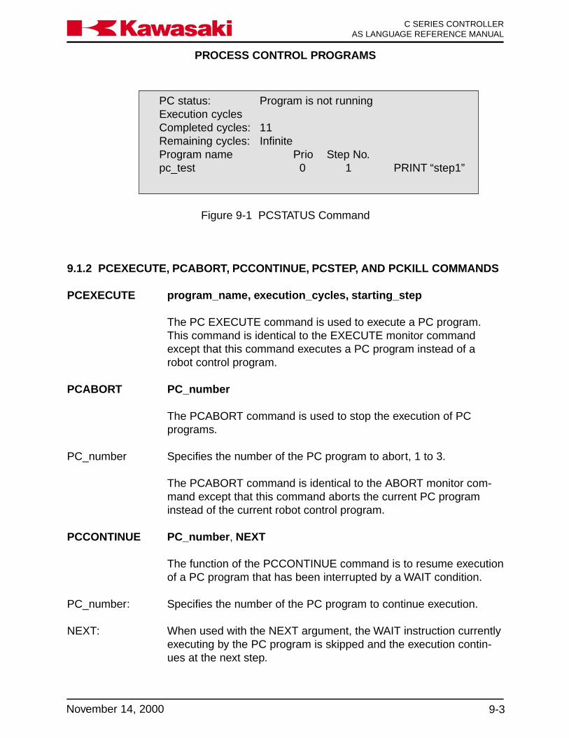
PROCESS CONTROL PROGRAMS
9-3November 14, 2000
Ka a aw s k C SERIES CONTROLLERAS LANGUAGE REFERENCE MANUAL
PC status: Program is not runningExecution cyclesCompleted cycles: 11Remaining cycles: InfiniteProgram name Prio Step No.pc_test 0 1 PRINT “step1”
Figure 9-1 PCSTATUS Command
9.1.2 PCEXECUTE, PCABORT, PCCONTINUE, PCSTEP, AND PCKILL COMMANDS
PCEXECUTE program_name, execution_cycles, starting_step
The PC EXECUTE command is used to execute a PC program.This command is identical to the EXECUTE monitor commandexcept that this command executes a PC program instead of arobot control program.
PCABORT PC_number
The PCABORT command is used to stop the execution of PCprograms.
PC_number Specifies the number of the PC program to abort, 1 to 3.
The PCABORT command is identical to the ABORT monitor com-mand except that this command aborts the current PC programinstead of the current robot control program.
PCCONTINUE PC_number, NEXT
The function of the PCCONTINUE command is to resume executionof a PC program that has been interrupted by a WAIT condition.
PC_number: Specifies the number of the PC program to continue execution.
NEXT: When used with the NEXT argument, the WAIT instruction currentlyexecuting by the PC program is skipped and the execution contin-ues at the next step.
PROCESS CONTROL PROGRAMS
C SERIES CONTROLLERAS LANGUAGE REFERENCE MANUAL
9-4 November 14, 2000
Ka a aw s k
The PCCONTINUE command is identical to the CONTINUE moni-tor command, except is used with process control programs insteadof robot control programs.
PCSTEP PC program_name, execution_cycles, starting_step
The PCSTEP command is used to execute a single step of a PCprogram.
PC program_name: Is the name of the PC program to execute one step at a time.
execution_cycles: Is the number of cycles for the PC program to execute with thePCSTEP command.
starting_step: Is the program step number to execute first.
PC KILL Removes the current PC program from active status.
A PC program cannot be removed from the PC program stack if it isexecuting.
The PCKILL command is identical to the KILL monitor command,except that it handles process control programs instead of robotcontrol programs.
9.1.3 PCSCAN COMMAND
PCSCAN time
The PCSCAN command is used to specify the length of time usedto process the PC program one time.
time: Is specified in increments of one second.
If the PCSCAN command is not used, the PC program is processedat the CPU speed.

ERROR CODES/TROUBLESHOOTING
10-1November 14, 2000
C SERIES CONTROLLERAS LANGUAGE REFERENCE MANUALKa a aw s k
10.0 ERROR CODES/TROUBLESHOOTING .......................................................... 10-210.1 Error Recovery .................................................................................................. 10-210.2 Error Codes....................................................................................................... 10-510.3 Troubleshooting Flowcharts ............................................................................ 10-84
ERROR CODES/TROUBLESHOOTING
C SERIES CONTROLLERAS LANGUAGE REFERENCE MANUAL
10-2 November 14, 2000
Ka a aw s k
10.0 ERROR CODES/TROUBLESHOOTING
This unit provides error recovery flowcharts, error code information, and error codetroubleshooting flow charts. In addition, typical causes and remedies for the errors arealso provided.
10.1 ERROR RECOVERY
Figure 10-1 shows troubleshooting processes that may be helpful if the controller be-comes unresponsive to commands or an error code has been encountered that cannotbe cleared. Troubleshooting should begin with confirmation of basic integrity of thesystem: ensure that the power supply is on and meeting supply requirements, all cablesare correctly attached, all circuit boards are properly installed and fully seated, all pe-ripheral equipment is wired correctly, software is properly configured, etc.
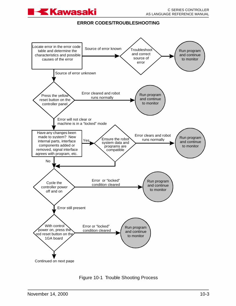
ERROR CODES/TROUBLESHOOTING
10-3November 14, 2000
C SERIES CONTROLLERAS LANGUAGE REFERENCE MANUALKa a aw s k
Source of error knownLocate error in the error codetable and determine the
characteristics and possiblecauses of the error
Source of error unknown
Press the yellowreset button on the
controller panel
Error will not clear ormachine is in a “locked” mode
Error cleared and robotruns normally
Error clears and robotruns normally
to monitorand continueRun program
Run programand continue
to monitor
Run programand continue
to monitor
Troubleshootand correctsource of
error
Yes Ensure the robotsystem data and
programs arecompatible
agrees with program, etc.removed, signal interface
components added orinternal parts, interfacemade to system? New
beenchangesanyHave
No
Cycle thecontroller power
off and on
Run programand continue
to monitor
Error or “locked” condition cleared
Error or “locked” condition cleared
Error still present
power on, press thered reset button on the
1GA board
With control
Continued on next page
to monitorand continueRun program
Figure 10-1 Trouble Shooting Process

ERROR CODES/TROUBLESHOOTING
C SERIES CONTROLLERAS LANGUAGE REFERENCE MANUAL
10-4 November 14, 2000
Ka a aw s k
Figure 10-2 Trouble Shooting Process (cont’d)
Createbackup information
files and initialize thesystem
Continued from previous pg
Run programand continue
to monitor
Error or “locked” condition cleared
Resetsystem settings notset to defaults after
initialization
Error still present
Remove the 1GA board from therack and allow RAMmemory to deplete
Reinstall 1GA board,initialize thesystem, zero
Error clears and robotruns normally Run program
and continueto monitor
Begin electricaltroubleshooting and repair if
qualified, call servicetechnician for further
assistance

ERROR CODES/TROUBLESHOOTING
10-5November 14, 2000
C SERIES CONTROLLERAS LANGUAGE REFERENCE MANUALKa a aw s k
10.2 ERROR CODES
This unit provides information about the error codes that are displayed on the multifunction panel or other user interfaces that provide display screen information. The errorcodes are listed in numerical order by code number with the message that is displayedwith the associated code. An expanded explanation of the message is provided alongwith possible methods to clear or prevent the specific error. Troubleshooting informationis preceded by a ⇒ symbol.
ERROR CODE -50 Warning! Cannot move along straight line in thisconfiguration.
Joint speed may exceed maximum, joints 4 and 6 aligned.
⇒ Change angle of joint 5, slow the speed, change to joint mode._____________________________________________________________________
ERROR CODE -57 Set low speed because of exceeding joint max. speed incheck.
When joint speed is checked with commanded speed, the difference exceeds accept-able range.
⇒ Slow the speed._____________________________________________________________________
ERROR CODE -100 Matrix Calculation Error.
The vector element of the matrix cannot be operated because of 0.
⇒ Change and recalculate value._____________________________________________________________________
ERROR CODE -101 Turn off motor power.
Motor power cannot turn on according to command and instruction.
⇒ Turn motor power OFF and execute command and instruction._____________________________________________________________________

ERROR CODES/TROUBLESHOOTING
C SERIES CONTROLLERAS LANGUAGE REFERENCE MANUAL
10-6 November 14, 2000
Ka a aw s k
ERROR CODE -102 Application is changed. Turn OFF & ON the control power.
The robot configuration was changed from spot welding/material handling to a paint/sealant application using AUX function 907.
⇒ Turn controller power OFF then ON._____________________________________________________________________
ERROR CODE -200 Cannot execute a program because motor power is OFF.
Program will not start because motor power is not on.
⇒ Turn motor power ON._____________________________________________________________________
ERROR CODE -201 Cannot execute a program in TEACH mode.
Programs cannot run when in the teach mode of operation.
⇒ Ensure that the controller is in the REPEAT mode of operation._____________________________________________________________________
ERROR CODE -202 Cannot execute a program because teach lock is ON.
Programs cannot be run with the teach lock in the ON position.
⇒ Turn the TEACH LOCK switch to OFF and execute the program again in repeatmode.
_____________________________________________________________________
ERROR CODE -207 Turn to HOLD at HOLD/RUN sw.
Occurs when an attempt to perform DO, STEP, MSTEP, CONTINUE, or EXECUTEcommands is made with the RUN/HOLD switch in the RUN position. Only applies if theCHECK HOLD system switch is ON.
⇒ Turn the RUN/HOLD switch to HOLD position._____________________________________________________________________
ERROR CODES/TROUBLESHOOTING
10-7November 14, 2000
C SERIES CONTROLLERAS LANGUAGE REFERENCE MANUALKa a aw s k
ERROR CODE -208 Teach pendant is not connected.
Hardwired switches for teach pendant and multi function panel must be jumpered andequipment configuration identified in environmental data functions.
⇒ Install teach pendant or configure system accordingly._____________________________________________________________________
ERROR CODE -211 Cannot edit a program because the TEACH LOCK switchis ON.
Programs cannot be edited if the TEACH LOCK switch is ON.
⇒ Turn TEACH LOCK switch OFF._____________________________________________________________________
ERROR CODE -300 Program is already running.
Occurs when an attempt is made to edit or execute a program that is currently running.
⇒ Stop the program prior to editing or checking._____________________________________________________________________
ERROR CODE -302 Can’t continue. Use EXEC.
The CONTINUE command is not permitted because of program selection status.
⇒ Use the EXECUTE command to start program._____________________________________________________________________
ERROR CODE -303 Robot is moving now.
Displayed if any of the following commands are entered while a program is running:EXECUTE, CONTINUE, TOOL, BASE, DO. SYSINIT or CYCLE START.
⇒ Stop the program or confirm the operation to be performed._____________________________________________________________________

ERROR CODES/TROUBLESHOOTING
C SERIES CONTROLLERAS LANGUAGE REFERENCE MANUAL
10-8 November 14, 2000
Ka a aw s k
ERROR CODE -304 Cannot execute because in error now. Reset error.
Occurs when attempt is made to start robot motion if an error has not been cleared.
⇒ Clear any errors and re-enter the command._____________________________________________________________________
ERROR CODE -306 Cannot execute with DO command.
Displayed when the DO command is entered with an instruction that is not of acceptableformat.
⇒ Execute the instruction from within a program or use acceptable instruction format forDO command.
_____________________________________________________________________
ERROR CODE -308 PC program is running.
Occurs when a PC program is running and instructions are entered that are not allowed.
⇒ Stop the PC program and enter the command._____________________________________________________________________
ERROR CODE -314 Cannot execute because the program is already used.
Occurs when a program being edited is selected to run by a CALL, ON, ONI or PCprogram instruction.
⇒ Stop editing the program or stop the program that is calling the program being edited._____________________________________________________________________
ERROR CODE -316 Waiting weld completion.
Displayed when a command to change the step is entered while a welding sequence isin progress.
⇒ Wait until after the weld sequence is completed or force a weld complete condition._____________________________________________________________________

ERROR CODES/TROUBLESHOOTING
10-9November 14, 2000
C SERIES CONTROLLERAS LANGUAGE REFERENCE MANUALKa a aw s k
ERROR CODE -317 Position offset error at last E-stop JTxx.
The error message is generated when an E-stop is applied and the position of the robotis not within a range of the commanded position. The error deviation range is specifiedin auxiliary function 42.
⇒ Before the error is reset, operators must be aware of the robot’s position within thework envelope.
_____________________________________________________________________
ERROR CODE -318 Waiting retract or extend pos. input signal.
One of the following operations were attempted when the robot was processing a spotweld sequence (waiting for the Retract/Extend signal after the weld complete signal hadbeen received).1. Cycle start (including EXECUTE, CONTINUE command).2. Program selection or step change.3. Record.
⇒ Input the Retract/Extend detection signal to the robot or press the WX key and waitoverride key on the multi function panel.
_____________________________________________________________________
ERROR CODE -319 Spot sequence is running.
Step change, program change, or program execution were attempted while the spotweld sequence was executing (after Retract/Extend input signal and weld completesignal have been received). For example, the robot is executing move delay time afterweld complete.
⇒ Perform step change, program registration or program execution after the spot weld-ing sequence.
_____________________________________________________________________
ERROR CODE -320 Cannot operate because teach pendant in operation.
You cannot perform functions on the personal computer while the multi function panel isin use.
⇒ Perform functions on the PC after the multi function panel has completed operation._____________________________________________________________________

ERROR CODES/TROUBLESHOOTING
C SERIES CONTROLLERAS LANGUAGE REFERENCE MANUAL
10-10 November 14, 2000
Ka a aw s k
ERROR CODE -324 Cannot execute with MC instruction.
MC instruction could not be carried out.
⇒ Use instruction which can be executed by MC instruction._____________________________________________________________________
ERROR CODE -325 Cannot execute the instruction in robot program.
Command and instruction cannot be used or executed.
⇒ Rewrite the command or instruction._____________________________________________________________________
ERROR CODE -326 Cannot delete because used by another command.
Cannot COPY, DELETE or XFER command because current step is being executed.
⇒ Perform DELETE commands after execution ends._____________________________________________________________________
ERROR CODE -327 Used in programs.
The variable used with the program was deleted.
⇒ Confirm the deleted variable._____________________________________________________________________
ERROR CODE -328 Used in editor.
When the program was used in the editor, the program was deleted._____________________________________________________________________
ERROR CODE -329 KILL or PCKILL to delete program.
Occurs when an attempt to delete a program is made and that program is still on thestack (selected).
⇒ Select another program or KILL/PC KILL the program, then delete._____________________________________________________________________

ERROR CODES/TROUBLESHOOTING
10-11November 14, 2000
C SERIES CONTROLLERAS LANGUAGE REFERENCE MANUALKa a aw s k
ERROR CODE -350 Illegal input data.
Input data from AS Language monitor command is improper for the instruction.
⇒ Enter data that is within acceptable range._____________________________________________________________________
ERROR CODE -351 Too many arguments.
Input data from AS Language editor commands exceeds the number of user specifieditems allowed by the format.
⇒ Verify input data and format of command._____________________________________________________________________
ERROR CODE -353 Input data is too big.
Data entered for the POINT or HERE commands exceeds the allowable range.
⇒ Enter data that is within acceptable range._____________________________________________________________________
ERROR CODE -360 Illegal WHERE parameter.
Occurs if data entered with the WHERE command is not an integer between 1 and 6.
⇒ Ensure that data is within acceptable range._____________________________________________________________________
ERROR CODE -361 Illegal PC number.
Unused_____________________________________________________________________
ERROR CODE -365 Illegal Robot number.
Unused_____________________________________________________________________

ERROR CODES/TROUBLESHOOTING
C SERIES CONTROLLERAS LANGUAGE REFERENCE MANUAL
10-12 November 14, 2000
Ka a aw s k
ERROR CODE -367 Illegal priority.
Priority level designation is wrong.
⇒ Input a correct priority level._____________________________________________________________________
ERROR CODE -368 Invalid coordinate value.
Upper limit value is less than value of lower limit.
⇒ Input the correct upper limit coordinates._____________________________________________________________________
ERROR CODE -371 External axis type and gun data mismatch.
The servo gun setting does not correspond to the type of external axis (set in AUX 160)and type of gun (set in AUX 114). This error is detected when motion begins for a stepwith a clamp signal set.
⇒ Confirm that the external axis and gun type data settings are correct.
ERROR CODE -400 Syntax error.
Occurs when an AS Language command is entered that does not follow the correctformat or contains typing or spelling errors.
⇒ Correct format or spelling of command/instruction._____________________________________________________________________
ERROR CODE -401 Invalid statement.
Occurs when an AS Language command is entered that has typing errors, incorrectspelling or is in the wrong format.
⇒ Correct the input data spelling or format._____________________________________________________________________
ERROR CODES/TROUBLESHOOTING
10-13November 14, 2000
C SERIES CONTROLLERAS LANGUAGE REFERENCE MANUALKa a aw s k
ERROR CODE -402 Ambiguous statement.
Displayed when an abbreviation is entered incorrectly or has missing letters.
⇒ Enter the correct abbreviation or entire command._____________________________________________________________________
ERROR CODE -403 Cannot use this command or instruction here.
Displayed because a program or monitor command was entered that could not beexecuted while a program is running.
⇒ Stop program execution or wait for completion._____________________________________________________________________
ERROR CODE -404 Cannot execute with DO command.
A program instruction that is not acceptable to use with the DO command was entered.
⇒ Place the desired instruction within a program or choose an acceptable instruction foruse with a DO command at the monitor prompt.
_____________________________________________________________________
ERROR CODE -405 Statement cannot be executed.
Occurs when the AS Language instruction entered was not acceptable for the mode ofoperation. For example: a monitor command was entered in the editor mode.
⇒ Use instructions and commands that are compatible with the input mode._____________________________________________________________________
ERROR CODE -406 Not a program instruction.
An instruction was entered into a program that is not a valid program instruction, i.e., amonitor command, editor command, etc.
⇒ Refer to the AS Language Manual for proper use of AS Language commands._____________________________________________________________________

ERROR CODES/TROUBLESHOOTING
C SERIES CONTROLLERAS LANGUAGE REFERENCE MANUAL
10-14 November 14, 2000
Ka a aw s k
ERROR CODE -407 Too many arguments.
Input data from AS Language editor commands exceeds the number of user specifieditems allowed by the format.
⇒ Verify input data and format of command._____________________________________________________________________
ERROR CODE -408 Missing argument.
Displayed when a DO command is not followed by an acceptable program instruction.
⇒ Correct the input and re-enter._____________________________________________________________________
ERROR CODE -410 Illegal expression.
A real number expression must be present for processing DECOMPOSE command(s).Also displayed when incorrect numerical information is entered with arguments.
⇒ Ensure correct format and numerical expressions are entered._____________________________________________________________________
ERROR CODE -411 Illegal function.
Occurs when functions are used to assign values to variables but the data is incompat-ible. For example: assigning XYZ coordinate data to precision points.
⇒ Ensure function is compatible with variables._____________________________________________________________________
ERROR CODE -412 Illegal argument of function.
Occurs when function and argument are not in correct format.
⇒ Use correct format for functions and arguments._____________________________________________________________________
ERROR CODES/TROUBLESHOOTING
10-15November 14, 2000
C SERIES CONTROLLERAS LANGUAGE REFERENCE MANUALKa a aw s k
ERROR CODE -413 Invalid variable (or program) name.
Displayed when illegal variable or program name is entered from the editor or monitormodes. For example: JM ##a (to many precision symbols) or CALL #a (not an accept-able program name).
⇒ Define program names and variables correctly._____________________________________________________________________
ERROR CODE -414 Illegal variable type.
Displayed when illegal variable is entered from editor or monitor modes.For example: b = #a + b (combining location and real variables using an arithmeticoperator).
⇒ Use compatible variable type for commands or instructions._____________________________________________________________________
ERROR CODE -415 Illegal array index.
Displayed when an attempt is made to use a variable that has previously been definedas an array. May also occur if the order of an array is reversed when editing or enteringmonitor commands.
⇒ Enter the correct array variable information._____________________________________________________________________
ERROR CODE-416 Missing parenthesis.
Occurs when parentheses are not entered as a pair, containing both a left and rightparenthesis.
⇒ Enter parentheses in left and right pairs._____________________________________________________________________
ERROR CODE -417 Expected to be a binary operator.
A non-binary operator has been entered where a command expected a binary operator.
⇒ Input a binary operator._____________________________________________________________________

ERROR CODES/TROUBLESHOOTING
C SERIES CONTROLLERAS LANGUAGE REFERENCE MANUAL
10-16 November 14, 2000
Ka a aw s k
ERROR CODE -419 Illegal qualifier.
Displayed when monitor commands are followed by unexpected qualifiers. For example:LIST W (expected characters would include P, L, and R for program, location, and realvariables; “W” causes error).
⇒ Use only acceptable qualifiers._____________________________________________________________________
ERROR CODE -420 Invalid label.
Occurs in the editor mode when a GOTO instruction is combined with a reserved char-acter. For example: GOTO #a (“#” is a reserved character).
⇒ Do not use reserved characters in label identification._____________________________________________________________________
ERROR CODE -421 Invalid name.
Displayed when an unidentified program, file, variable, etc., is used in a command.
⇒ Use only names that have been defined._____________________________________________________________________
ERROR CODE -422 Missing expected character.
Occurs when commands or instructions are entered with an incorrect format. For ex-ample: TOOL a=b (TOOL a would be correct, “=b” causes error).
⇒ Use correct format for commands and instructions._____________________________________________________________________
ERROR CODE -423 Illegal switch name.
Displayed when a system switch is incorrectly identified. For example: SWITCH light(there is no system switch named “light”).
⇒ Use only available switch names._____________________________________________________________________

ERROR CODES/TROUBLESHOOTING
10-17November 14, 2000
C SERIES CONTROLLERAS LANGUAGE REFERENCE MANUALKa a aw s k
ERROR CODE -424 Ambiguous switch name.
Displayed when a switch name has been entered that is not available for the softwareversion that is operating in the controller.
⇒ Use only system switches that are compatible with the software version that is operat-ing.
_____________________________________________________________________
ERROR CODE -425 Illegal format qualifier.
Occurs when the TYPE or PRINT command is not used with an acceptable formatportion of the instruction.
⇒ Use only specified format instructions with TYPE and PRINT commands._____________________________________________________________________
ERROR CODE -426 Duplicate statement label.
A specific program label name can only be used once per program. Error is displayed ifthe same label name is entered a second time in the same program.
⇒ Use label names only once per program._____________________________________________________________________
ERROR CODE -430 Cannot define as array.
A non-array variable with the same name as the array variable that was attempted to becreated, already exists.
⇒ Use a different name for the new variable. Refer to the AS Language Manual forproper use of AS Language commands.
_____________________________________________________________________
ERROR CODE -431 Dimension exceeds 3.
Attempted to create an array variable with more than 3 dimensions.
⇒ Refer to the AS Language Manual for proper use of AS Language commands._____________________________________________________________________
ERROR CODES/TROUBLESHOOTING
C SERIES CONTROLLERAS LANGUAGE REFERENCE MANUAL
10-18 November 14, 2000
Ka a aw s k
ERROR CODE -432 Different dimensional array exist.
An array variable with same name but a different number of dimensions already exists.
⇒ Change the name of the new variable or provide the same number of dimensions asthe existing variable. Refer to the AS Language Manual for proper use of AS Lan-guage commands.
_____________________________________________________________________
ERROR CODE -433 Array variable exist.
Attempted to create a non-array variable with the same name as an existing array vari-able.
⇒ Confirm array variable exists. Select new name for non-array variable or select arrayvariable.
_____________________________________________________________________
ERROR CODE -434 Non array variable exist.
Attempted to create an array variable with the same name as an existing non-arrayvariable.
⇒ Confirm non-array variable exists. Select new name for array variable or select non-array variable.
_____________________________________________________________________
ERROR CODE -435 Array variable expected.
A non-array variable exists with the same name as the array variable that was specifiedfor the decompose instruction.
⇒ Select a new name for the array variable that was specified for the decompose in-struction.
_____________________________________________________________________
ERROR CODE -440 Local variable expected.
A subroutine call to a program with a local variable found a program with the samename but without a local variable.
⇒ Refer to the AS Language Manual for proper use of AS Language commands._____________________________________________________________________

ERROR CODES/TROUBLESHOOTING
10-19November 14, 2000
C SERIES CONTROLLERAS LANGUAGE REFERENCE MANUALKa a aw s k
ERROR CODE -441 Unexpected suffix.
No data was provided in the brackets of an array variable.
⇒ Refer to the AS Language Manual for proper use of AS Language commands._____________________________________________________________________
ERROR CODE -442 Mismatch of arguments at subroutine call.
The order of the local variable in the called program and the order of the local variable inthe actual program are different.
⇒ Check the order of the local variable in the actual program and modify the subroutinecall accordingly. Refer to the AS Language Manual for proper use of AS Languagecommands.
_____________________________________________________________________
ERROR CODE -443 Mismatch of argument type at subroutine call.
The type of argument, i.e. location variable, real variable, is different than the argumentin the origin program.
⇒ Correct the type of the argument in the called program or origin program._____________________________________________________________________
ERROR CODE -450 Control structure error.
Displayed when an illegal program control flow structure is evaluated.
⇒ Use correct syntax and components in control flow structures._____________________________________________________________________
ERROR CODE -451 Step:xxx Wrong END statement.
Occurs when an illegal END statement is entered during editing.
⇒ Use correct syntax and components in control flow structures._____________________________________________________________________
ERROR CODES/TROUBLESHOOTING
C SERIES CONTROLLERAS LANGUAGE REFERENCE MANUAL
10-20 November 14, 2000
Ka a aw s k
ERROR CODE -452 Step:xxx Extra END statement.
Occurs when an extra END statement is present and there is no corresponding struc-ture.
⇒ Use correct syntax and components in control flow structures, check structure ofEND statements.
_____________________________________________________________________
ERROR CODE -453 Step:xxx Cannot terminate DO with END.
This error is displayed when the control flow structure DO….UNTIL is entered with anEND statement .
⇒ Use correct syntax and components in control flow structures._____________________________________________________________________
ERROR CODE -454 Step:xxx No VALUE statement after CASE.
Occurs when the control flow structure CASE OF….END is entered without a value toevaluate.
⇒ Use correct syntax and components in control flow structures._____________________________________________________________________
ERROR CODE -455 Step:xxx Preceding IF missing.
Displayed when control flow structure does not contain the correct structure forIF…THEN… ELSE…END commands.
⇒ Use correct syntax and components in control flow structures._____________________________________________________________________
ERROR CODE -456 Step:xxx Preceding CASE missing.
Displayed when control flow structure does not contain the correct structure forCASE…of… VALUE…ANY…END commands.
⇒ Use correct syntax and components in control flow structures._____________________________________________________________________
ERROR CODES/TROUBLESHOOTING
10-21November 14, 2000
C SERIES CONTROLLERAS LANGUAGE REFERENCE MANUALKa a aw s k
ERROR CODE -457 Step:xxx Preceding DO missing.
Displayed when control flow structure does not contain the correct structure forDO…UNTIL.
⇒ Use correct syntax and components in control flow structures._____________________________________________________________________
ERROR CODE -458 Step:xxx Can’t find END of xxx.
Occurs when control flow structure that requires an END statement does not contain thenecessary END.
⇒ Use correct syntax and components in control flow structures._____________________________________________________________________
ERROR CODE -459 Step:xxx Too many control structures.
Occurs when 11 layers of control flow structure are exceeded.
⇒ Limit control flow structure to 11 layers._____________________________________________________________________
ERROR CODE -460 Variable (or program) already exists.
Displayed when a variable is entered that is already part of the system memory. Forexample: a location named “weld1” is entered when a program named “weld1” is alreadyin the memory.
⇒ Do not use variable names for more than one item._____________________________________________________________________
ERROR CODE -461 Variable of different type already exists.
Displayed when a variable is entered that is already part of the system memory. Forexample: a location named “weld1” is entered when a program named “weld1” is alreadyin the memory.
⇒ Do not use variable names for more than one item._____________________________________________________________________

ERROR CODES/TROUBLESHOOTING
C SERIES CONTROLLERAS LANGUAGE REFERENCE MANUAL
10-22 November 14, 2000
Ka a aw s k
ERROR CODE -464 Internal buffer over.
Attempted to solve a complex mathematical equation in a program.
⇒ Rewrite to reduce the complexity of the operations required to solve the equation._____________________________________________________________________
ERROR CODE -465 Undefined Variable (or program).
Attempt call a subroutine or process a variable that does not exist.
⇒ Verify the variable or program exists._____________________________________________________________________
ERROR CODE -466 Illegal clock value.
Time or date was entered in the wrong format.
⇒ Re-enter the values correctly; time - military, date - yy/mm/dd._____________________________________________________________________
ERROR CODE -470 Expect “=”.
The argument is missing the necessary “=”.
⇒ Check the argument and correct it._____________________________________________________________________
ERROR CODE -471 Expect “)”.
The argument is missing the necessary “)”.
⇒ Check the argument and correct it._____________________________________________________________________
ERROR CODE -472 Expect “]”.
The argument is missing the necessary “]”.
⇒ Check the argument and correct it._____________________________________________________________________

ERROR CODES/TROUBLESHOOTING
10-23November 14, 2000
C SERIES CONTROLLERAS LANGUAGE REFERENCE MANUALKa a aw s k
ERROR CODE -473 “Expect “TO”.
The argument is missing the necessary “TO”.
⇒ Check the argument and correct it._____________________________________________________________________
ERROR CODE -474 “Expect “BY”.
The argument is missing the necessary “BY”.
⇒ Check the argument and correct it._____________________________________________________________________
ERROR CODE -475 Expect “:”.
The argument is missing the necessary “:”.
⇒ Check the argument and correct it._____________________________________________________________________
ERROR CODE -476 “Expect ”ON/OFF”.
An instruction other than ON/OFF was used with a SYSTEM SWITCH.
⇒ Check the ON/OFF status SYSTEM SWITCH and input it correctly._____________________________________________________________________
ERROR CODE -490 Program name not specified.
Displayed when no program is on the stack and the EDIT command is entered withoutspecifying a program name.
⇒ Identify the name of the program to be edited._____________________________________________________________________
ERROR CODE -494 Program is interlocked by another procedure.
Attempt to edit a running program was made.
⇒ Stop program execution before editing the program._____________________________________________________________________

ERROR CODES/TROUBLESHOOTING
C SERIES CONTROLLERAS LANGUAGE REFERENCE MANUAL
10-24 November 14, 2000
Ka a aw s k
ERROR CODE -499 Invalid statement.
Occurs when the program is executed and instructions are encountered that cannot beprocessed as AS Language commands.
⇒ Use correct syntax and components for AS Language commands._____________________________________________________________________
ERROR CODE -507 Communication error.
When a vision system is incorporated and the transmission of data is interrupted (trans-mission line problem or stoppage of the program) this error will be displayed.
_____________________________________________________________________
ERROR CODE -514 Device is not ready.
Unused_____________________________________________________________________
ERROR CODE -523 Illegal file name.
Unused_____________________________________________________________________
ERROR CODE -543 Data read error.
Unused_____________________________________________________________________
ERROR CODE -545 Record inhibited. Set “”record accept”” and operate again.
Displayed when an attempt was made to enter data, but the RECORD INHIBIT systemswitch was set to inhibit.
⇒ Change the setting of the RECORD INHIBIT system switch._____________________________________________________________________
ERROR CODE -551 Cannot open the file.
Unused_____________________________________________________________________
ERROR CODES/TROUBLESHOOTING
10-25November 14, 2000
C SERIES CONTROLLERAS LANGUAGE REFERENCE MANUALKa a aw s k
ERROR CODE -580 Retry error.
Occurs when there is a problem with the communication link between the controller anda host communication PC.
⇒ Check the integrity of the controller and host PC link._____________________________________________________________________
ERROR CODE -581 Stop of process.
(Option: Host communication I correspondence.)Refer to the host communication manual for details._____________________________________________________________________
ERROR CODE -583 Receive not data after receive request.
(Option: Host communication I correspondence.)Refer to the host communication manual for details._____________________________________________________________________
ERROR CODE -584 Too long receive data (MAX=255 character).
(Option: Host communication I correspondence.)Refer to the host communication manual for details._____________________________________________________________________
ERROR CODE -585 Abnormal data (EOT) received in communicating.
(Option: Host communication I correspondence.)Refer to the host communication manual for details._____________________________________________________________________
ERROR CODE -586 Time out.
(Option: Host communication I correspondence.)Refer to the host communication manual for details._____________________________________________________________________

ERROR CODES/TROUBLESHOOTING
C SERIES CONTROLLERAS LANGUAGE REFERENCE MANUAL
10-26 November 14, 2000
Ka a aw s k
ERROR CODE -591 Illegal device number.
Two types of selections are possible for the serial port. This error occurs when portnumbers other than the sensor port are specified.
(Option: Host communication I correspondence.)Refer to the host communication manual for details.
_____________________________________________________________________
ERROR CODE -596 Cannot attach terminal.
The prompt instruction was executed by two or more programs at the same time.
⇒ Do not execute the prompt instruction from two or more programs at the same time._____________________________________________________________________
ERROR CODE -597 Cannot attach communication port.
The RECEIVE instruction and the SEND instruction were executed by two or moreprograms at the same time.
⇒ Do not execute these instructions from two or more programs at the same time._____________________________________________________________________
ERROR CODE -598 Cannot execute on this terminal.
Attempt was made to execute a command that cannot be used at that terminal. Somecommands can only be used at the multi function panel and some only at the PC.
⇒ Use the above command from the proper terminal._____________________________________________________________________
ERROR CODE -599 Waiting input data for PROMPT. Connect input device.
The input device specified by the prompt command, i.e., PC or MFP, was not connected.
⇒ Verify that the specified device is connected._____________________________________________________________________
ERROR CODE -600 Motor power OFF. Displayed whenever an emergencystop is encountered.
⇒ Reset emergency stop button and reapply motor power._____________________________________________________________________
ERROR CODES/TROUBLESHOOTING
10-27November 14, 2000
C SERIES CONTROLLERAS LANGUAGE REFERENCE MANUALKa a aw s k
ERROR CODE -610 Weld completion time over.
Occurs when a weld complete signal is not received in a specified time period.
⇒ Override the wait condition, ensure that weld complete signal specifications arecorrectly identified, check the operation of the weld gun or controller.
_____________________________________________________________________
ERROR CODE -611 Illegal extend (retract) output signal.
Occurs when the output signals for the extend and retract operation of a spot weldingapplication are not properly set.
⇒ Check the setting in auxiliary function 114._____________________________________________________________________
ERROR CODE -612 Weld fault input.
Displayed when the controller receives a weld fault signal.
⇒ Check operation of welding equipment, ensure signal numbers are correctly set._____________________________________________________________________
ERROR CODE -613 Retract pos. monitor error.
Occurs when the input signal for the retract operation of a spot welding application is notreceived.
⇒ Check the operation of welding equipment, check the signal number setting in auxil-iary function 114-10.
_____________________________________________________________________
ERROR CODE -614 Extend pos. monitor error.
Occurs when the input signal for the extend operation of a spot welding application isnot received.
⇒ Check the operation of welding equipment, check the signal number setting in auxil-iary function 114-10.
_____________________________________________________________________

ERROR CODES/TROUBLESHOOTING
C SERIES CONTROLLERAS LANGUAGE REFERENCE MANUAL
10-28 November 14, 2000
Ka a aw s k
ERROR CODE -615 Weld completion signal is already inputted.
Displayed when the weld complete signal has been received before the weld initiateoutput has not been issued.
⇒ Check operation of welding equipment, check the signal number setting in auxiliaryfunction 114-11.
_____________________________________________________________________
ERROR CODE -616 Gun retract position mismatch.
In the check mode, retractable gun output signals are monitored and compared to open/close data for a specific step. If the data does not compare, an error is displayed.
⇒ Check settings in clamp conditions, check operation of gun with clamp key._____________________________________________________________________
ERROR CODE -631 Cannot achieve desired pressure.
The gun does not obtain the set closing pressure within 5 seconds after the gun startsclosing.
1. Tip wear measurement is not executed.2. Incorrect taught point (closing pressure is not defined for the recorded position).3. Closing pressure is set too high.
⇒ Perform the tip wear measurement.⇒ Reteach the point.⇒ Decrease the closing pressure.
_____________________________________________________________________
ERROR CODE -632 Gun chip[tip] stick.
Indicates that the tips are stuck. More power is required to open the gun, following aweld, than the stuck detection value, set in AUX 114-41, WELDING DETECTION(0:NOCHK) [kgf].
If the stuck detection value is set below the power level required for normal operation,the gun cannot operate properly and the error is set.
⇒ If the gun is stuck, release it manually.⇒ If the gun is not stuck, verify that the stuck detection value (AUX 114-41, WELDING
DETECTION(0:NO CHK) [kgf]) is set correctly. This setting may need to be in-creased.
_____________________________________________________________________

ERROR CODES/TROUBLESHOOTING
10-29November 14, 2000
C SERIES CONTROLLERAS LANGUAGE REFERENCE MANUALKa a aw s k
ERROR CODE -633 Copper plate abrasion over the limit. step=*.
The copper backing plate wear exceeds the copper plate wear limit (AUX 114-12). Theerror is detected when the gun executes a weld.
⇒ Replace the copper backing plate._____________________________________________________________________
ERROR CODE -634 Not dedicated encoder and brake power off signal.
The gun separation accept signal is not received during a gun change.
⇒ From AUX 111 Dedicated Input Signal, set the gun separation accept signal number(encoder brake power supply OFF control signal).
_____________________________________________________________________
ERROR CODE -641 Now servo gun is disconnected or a different gun.
The robot executes a step when a gun is not attached to the tool changer or the gunnumber in the tool changer is different than the gun number for the program step.
⇒ Execute the step in manual mode or manually install the correct gun. In the teach orcheck mode, verify connection of the gun by pressing the connect/separate button.
⇒ If the correct gun is attached to the tool changer, confirm that the gun signal number(AUX 114-41, GUN CONNECTION SIGNAL) is correct. From the MONITOR (INPUTSIGNAL) screen, confirm that the signal number is received.
⇒ Inspect the connectivity from the gun to the 1FG board.⇒ Temporarily set the gun connect signal number (AUX 114-41, GUN CONNECTION
SIGNAL) to 0 (when the gun connect number is set to 0, the error is not detected);ensure that the correct gun is in the tool changer. Repair the gun connection and setthe gun connect signal number as soon as possible.
_____________________________________________________________________

ERROR CODES/TROUBLESHOOTING
C SERIES CONTROLLERAS LANGUAGE REFERENCE MANUAL
10-30 November 14, 2000
Ka a aw s k
ERROR CODE -642 Calibration is not completed.
The controller terminates the calibration operation after a gun change.
⇒ Reset the error and perform a manual gun change._____________________________________________________________________
ERROR CODE -643 Measure of chip abrasion (stage 1) was not executed.
When the tip wear measurement program stage 2 (reference plate) is attempted, withoutfirst performing stage 1.
⇒ Execute tip wear measurement program stage 1 prior to executing stage 2._____________________________________________________________________
ERROR CODE -644 Work sensing signal (gun_chip[tip] touch sig) is not estab-lished.
A workpiece thickness measurement is attempted, when the gun tip touch signal (set inAUX 114-41) has not been received.
⇒ Set the gun tip touch signal number (AUX 114-41)._____________________________________________________________________
ERROR CODE -645 Cannot weld because of abnormal thickness.
The thickness of the workpiece is out of tolerance.
Probable causes:
1. Defective workpiece.2. Incorrect positioning of the workpiece3. A gap between the two panels being welded.4. Current tip wear (AUX 114-41) and actual tip wear are different.
⇒ Inspect the workpiece. Measure the thickness and positioning; replace workpieceand/or correct abnormal positioning.
⇒ Execute the tip wear measurement program. Manually measure the tip wear; com-pare these measurements to the current tip wear data (AUX 114-41).
_____________________________________________________________________

ERROR CODES/TROUBLESHOOTING
10-31November 14, 2000
C SERIES CONTROLLERAS LANGUAGE REFERENCE MANUALKa a aw s k
ERROR CODE -646 Servo welding gun mechanical parameter is not estab-lished.
When connecting a new gun, the mechanical parameters are not defined.
⇒ Define the parameters in AUX 114-12 SPOT WELD GUN DEFINITION and AUX114-42 SERVO WELDING MECHANICAL PARA.
_____________________________________________________________________
ERROR CODE -653 Illegal DOUBLE OX output.
When Double type signals are used, if either output in the pair is turned ON, the otherturns OFF. An instruction to turn both outputs ON or turn both outputs OFF (OX=+1,2 orOX=-1,2) causes this error.
⇒ Modify using the teaching screen._____________________________________________________________________
ERROR CODE -654 Cannot use DOUBLE OX.
When Double type signals are used, if either output in the pair is turned ON, the otherturns OFF. An instruction (BITS, PULSE, DELSIG, etc.) to change the state of eitheroutput causes this error to occur.
⇒ Modify using the teaching screen._____________________________________________________________________
ERROR CODE -660 Gun chip abrasion over the limit.
The maximum tip wear limit (AUX 114-41 MAX ABRASION MOVING/FIXED[mm]) isexceeded.
⇒ Replace the tips._____________________________________________________________________
ERROR CODE -662 Start point position error for circle.
The robot was stopped after it began executing a circular motion and moved 4 mm ormore away from its calculated path (jogging or brake slippage, etc.). Attempting tocontinue execution of the path from this position will result in this error.
⇒ Move the robot closer to the calculated path or restart the program a step prior to thecircular path.
_____________________________________________________________________
ERROR CODES/TROUBLESHOOTING
C SERIES CONTROLLERAS LANGUAGE REFERENCE MANUAL
10-32 November 14, 2000
Ka a aw s k
ERROR CODE -671 Cannot execute in check back mode.
The program reached an instruction which cannot be executed in check back mode.
⇒ Execute after selecting a step that can be checked backward. If possible, checkforward.
_____________________________________________________________________
ERROR CODE -672 Cannot execute in ONE program.
The instructions specified in the ONE program area not valid for this type of program.
⇒ Refer to the AS Language manual for proper use of the AS Language commands._____________________________________________________________________
ERROR CODE -673 Angle between JT2 and JT3 is out of range at start loca-tion.
Movement from the current position to the start location position would cause JT2 andJT3 to move beyond their limits.
⇒ Modify the position of the start location of the program._____________________________________________________________________
ERROR CODE -674 Angle between JT2 and JT3 is out of range at end loca-tion.
Movement from the current position to the end location position would cause JT2 andJT3 to move beyond their limits.
⇒ Modify the position of the end location of the program._____________________________________________________________________
ERROR CODE -675 Terminal is not connected.
A PRINT, TYPE, or PROMPT command is specified for display on a PC that is notconnected.
⇒ Verify the PC connections or modify the commands for display on the MFP._____________________________________________________________________

ERROR CODES/TROUBLESHOOTING
10-33November 14, 2000
C SERIES CONTROLLERAS LANGUAGE REFERENCE MANUALKa a aw s k
ERROR CODE -676 Cannot input /output to multi function panel.
A PRINT, TYPE, or PROMPT command is specified for display on the MFP, althoughnoMFP connection is present.
⇒ Verify the MFP connections or modify the commands for display on the PC._____________________________________________________________________
ERROR CODE -691 Cannot change two or more guns at the same step.
The operator attempts to execute a step with more than one gun change.
⇒ Edit the program so that there is only one gun change per step._____________________________________________________________________
ERROR CODE -692 Gun is connected other.
The tool changer attempts to connect to a gun that is already connected to another toolchanger or is missing.
⇒ Select a different gun or disconnect the gun from the other tool changer.
NOTE
The following are conventional robot errors; however,when they occur for the servo gun axis, the following ad-ditional causes are possible.
_____________________________________________________________________
ERROR CODES/TROUBLESHOOTING
C SERIES CONTROLLERAS LANGUAGE REFERENCE MANUAL
10-34 November 14, 2000
Ka a aw s k
ERROR CODE -700 No free memory.
No free memory is available to teach or edit programs.
⇒ Delete unused programs and variables, or, expand system memory to maintain therequired capacity.
_____________________________________________________________________
ERROR CODE -800 Program does not exist.
No program is on the stack at the time of cycle start or execution command (without aprogram being specified).
⇒ Identify program to be executed._____________________________________________________________________
ERROR CODE -801 No program step. The step specified for execution doesnot exist.
⇒ Select valid step numbers for execution._____________________________________________________________________
ERROR CODE -802 Nonexistent label.
Occurs when executing the GOTO command and the destination label is not defined.
⇒ Ensure valid labels are used within the program._____________________________________________________________________
ERROR CODE -803 Undefined variable. Variable data for a specific argumentin a command is not defined.
⇒ Ensure variables are properly defined._____________________________________________________________________
ERROR CODE -804 Undefined location data.
The location variable for the BASE, TOOL or POINT command is not specified. Also, anamed position in a program is not defined in system memory.
⇒ Define all locations identified in programs._____________________________________________________________________

ERROR CODES/TROUBLESHOOTING
10-35November 14, 2000
C SERIES CONTROLLERAS LANGUAGE REFERENCE MANUALKa a aw s k
ERROR CODE -805 Undefined string variable. String variables that are evalu-ated by ASC and LEN functions are not defined.
⇒ Define the string variables to be evaluated or correct the name of the string variableused for evaluation._____________________________________________________________________
ERROR CODE -807 Undefined program or label.
The program name or label associated with an ON or ONI command does not exist.
⇒ Define the program or label used with the ON or ONI command._____________________________________________________________________
ERROR CODE -808 Illegal value. The numeric value entered exceeds theupper or lower limits of the acceptable range.
⇒ Enter data that is within acceptable range._____________________________________________________________________
ERROR CODE -809 Undefined array suffix.
Attempt to process an array variable with undefined suffixes, i.e., attempting to processA=B[C,D,E], but C, D, E have no values.
⇒ Rewrite the program to define the array suffix before attempting to process the array._____________________________________________________________________
ERROR CODE -810 Divided by zero.
Occurs when the system encounters a mathematical evaluation that involves division by“0”. Typically associated with the FRAME function and circular interpolation.
⇒ Check data source for calculations._____________________________________________________________________
ERROR CODE -812 Character string is too long.
Character strings associated with arithmetic or comparative operators or the LEN func-tion are too long.
⇒ Correct the program._____________________________________________________________________

ERROR CODES/TROUBLESHOOTING
C SERIES CONTROLLERAS LANGUAGE REFERENCE MANUAL
10-36 November 14, 2000
Ka a aw s k
ERROR CODE -813 Illegal exponential operation.
Numeric values that have exponents must be positive in value.
⇒ Correct equations in program._____________________________________________________________________
ERROR CODE -814 Expression too complicated.
A numeric calculation too complex to be evaluated was encountered.
⇒ Simplify mathematical equations._____________________________________________________________________
ERROR CODE -815 No expressions to evaluate.
The type of data in an argument is incompatible with the operation being performed.
⇒ Correct the program to evaluate compatible expressions._____________________________________________________________________
ERROR CODE -816 Unexpected error while evaluating expression.
Occurs when the system is evaluating the argument in an expression and the data ofthe argument is found to be incompatible or missing.
⇒ Correct the program so that data is compatible with arguments and expressions._____________________________________________________________________
ERROR CODE -817 SQRT parameter is negative.
In the argument of a SQRT function, a negative number was entered for evaluation.
⇒ Do not enter negative numbers for evaluation by the SQRT function._____________________________________________________________________
ERROR CODE -820 Illegal array index.
Occurs when the array subscript number exceeds the acceptable range from 0 to 9999.
⇒ Ensure the range of array subscripts is acceptable._____________________________________________________________________

ERROR CODES/TROUBLESHOOTING
10-37November 14, 2000
C SERIES CONTROLLERAS LANGUAGE REFERENCE MANUALKa a aw s k
ERROR CODE -821 Illegal argument value.
Displayed when the parameter specified for an command or instruction is illegal. Forexample: TOOL 2112 (after the TOOL command a defined transformation location or nullis expected, 2112 causes error).
⇒ Use correct argument values._____________________________________________________________________
ERROR CODE -822 Illegal joint number.
The joint numbered entered does not exist or is in the wrong format.
⇒ Retype the command using the correct format._____________________________________________________________________
ERROR CODE -823 Illegal signal number.
This is displayed when the SIG or BITS command is used and the specified signalnumber is beyond the range permitted by the system configuration.
⇒ Use acceptable signal numbers for system configuration._____________________________________________________________________
ERROR CODE -824 Illegal timer number.
Displayed when a timer was specified that was not within the acceptable range of be-tween 1 and 10.
⇒ Specify timers in the range between 1 and 10._____________________________________________________________________
ERROR CODE -825 Illegal signal number.
When the RUNMASK, SIGNAL, BITS, PULSE, or SWAIT commands are used with asignal number that exceeds the range permitted by system configuration, this error isdisplayed.
⇒ Check signal number specified in instruction and ensure it is within system configura-tion.
_____________________________________________________________________
ERROR CODES/TROUBLESHOOTING
C SERIES CONTROLLERAS LANGUAGE REFERENCE MANUAL
10-38 November 14, 2000
Ka a aw s k
ERROR CODE -826 Illegal clamp number.
Displayed when the clamp number entered exceeds the maximum permitted by systemconfiguration.
⇒ Use only clamp numbers that are supported by system configuration._____________________________________________________________________
ERROR CODE -827 Illegal time value.
Displayed when a negative number is entered as part of a DELAY or TIMER command.
⇒ Correct the time setting to a positive number._____________________________________________________________________
ERROR CODE -828 No value set.
Occurs when an instruction like the BITS command is evaluated and there is no corre-sponding value set.
⇒ Correct program code to evaluate existing values._____________________________________________________________________
ERROR CODE -829 Illegal signal number.
This error is displayed when the RUNMASK, SIGNAL, BITS, PULSE, or SWAIT com-mands are used with a signal number that exceeds the range permitted by systemconfiguration.
⇒ Check signal number specified in the instruction and ensure it is within system con-figuration.
_____________________________________________________________________
ERROR CODE -832 Illegal time input data.
Occurs when erroneous data has been entered in the setting of the TIME and DATEfunction. For example: a date of Feb. 30.
⇒ Input time and date information correctly, mm/dd/yy._____________________________________________________________________

ERROR CODES/TROUBLESHOOTING
10-39November 14, 2000
C SERIES CONTROLLERAS LANGUAGE REFERENCE MANUALKa a aw s k
ERROR CODE -834 Program name already exists.
When using the RENAME command a new program name must be specified. If anexisting name is used to rename a program this error will be displayed.
⇒ Specify unused program names when renaming programs._____________________________________________________________________
ERROR CODE -835 Can’t KILL because the program is running.
Displayed when an attempt was made to KILL a program that was in the process ofexecuting.
⇒ Stop program execution with HOLD or ABORT commands before program is re-moved from the stack with a KILL command.
_____________________________________________________________________
ERROR CODE -837 Cannot use dedicated signal.
Occurs when a previously dedicated signal was used as a general purpose signal.
⇒ Use signals that have not been dedicated for general functions._____________________________________________________________________
ERROR CODE -838 Not RPS mode.
Occurs when the required input signals are not dedicated at the time an attempt to runan externally selected program is made.
⇒ If RPS is to be used the necessary signals must be dedicated._____________________________________________________________________
ERROR CODE -839 Cannot use negative number. Displayed when a negativenumber has been used in conjunction with the PULSE orACCURACY commands.
⇒ Use only positive numbers in the acceptable range for the PULSE and ACCURACYcommands.
_____________________________________________________________________

ERROR CODES/TROUBLESHOOTING
C SERIES CONTROLLERAS LANGUAGE REFERENCE MANUAL
10-40 November 14, 2000
Ka a aw s k
ERROR CODE -840 Too many subroutines.
Occurs when more than 20 subroutines are nested with EXTCALL or CALL instructions.
⇒ Do not exceed 20 nested subroutines._____________________________________________________________________
ERROR CODE -842 Nonexistent subroutine. Displayed when the programidentified by a CALL, ON, or ONI does not exist.
⇒ Select only existing programs to be run as subroutines._____________________________________________________________________
ERROR CODE -846 No program exist.
Pertinent program does not exist in DIRECTORY and LIST commands.
⇒ Correct program or make program._____________________________________________________________________
ERROR CODE -850 Out of absolute lower limit.
Displayed when an attempt has been made to set the software lower limits of robottravel to a value that is too low.
⇒ Set lower software travel limits to an acceptable range._____________________________________________________________________
ERROR CODE -851 Out of absolute upper limit.
Displayed when an attempt has been made to set the software upper limits of robottravel to a value that is too high.
⇒ Set upper software travel limits to an acceptable range._____________________________________________________________________
ERROR CODE -852 Out of user lower limit.
Displayed when an attempt has been made to set the software lower limits of robottravel to a value that is too low.
⇒ Set lower software travel limits to an acceptable range._____________________________________________________________________

ERROR CODES/TROUBLESHOOTING
10-41November 14, 2000
C SERIES CONTROLLERAS LANGUAGE REFERENCE MANUALKa a aw s k
ERROR CODE -853 Out of user upper limit.
Displayed when an attempt has been made to set the software upper limits of robottravel to a value that is too high.
⇒ Set upper software travel limits to an acceptable range._____________________________________________________________________
ERROR CODE -854 Current position of jt* is out of range.
This error can occur when two guns are used. When a program is taught with one gun,and a second gun is used to perform the program, the second gun may not be able toexecute a program step. This may be due to differences in the physical size or mechani-cal characteristics of the two guns.
⇒ Reteach the point(s), using a configuration which allows the robot to reach the de-sired position with both guns.
_____________________________________________________________________
ERROR CODE -855 Motion start location of jt-x is out of range.
Prior to beginning a program or motion to a step, the software has calculated the loca-tion to be outside of the allowable upper or lower software limits.
⇒ Correct location to within working envelope or expand software limits to accept loca-tion.
_____________________________________________________________________
ERROR CODE -856 Motion and location of jt-x is out of range.
While executing a motion to a step, the software has calculated the location destinationof the specific joint number to be outside of the allowable upper or lower software limits.
⇒ Correct location to within working envelope or expand software limits to accept loca-tion.
_____________________________________________________________________

ERROR CODES/TROUBLESHOOTING
C SERIES CONTROLLERAS LANGUAGE REFERENCE MANUAL
10-42 November 14, 2000
Ka a aw s k
ERROR CODE -857 Destination is out of range.
While executing a motion to a step, the software has calculated the location destinationof all joints to be outside of the allowable upper or lower software limits.
⇒ Correct location to within working envelope or expand software limits to accept loca-tion.
_____________________________________________________________________
ERROR CODE -858 Illegal configuration for linear motion.
System software has determined that the start and end points of a linear move willcause the robot to exceed the acceptable motion parameters.
⇒ Change motion interpolation to a joint move; move location to avoid configuration._____________________________________________________________________
ERROR CODE -871 Illegal joint number.
Occurs when the DRIVE command is used and specifies a joint number that is not partof the robot configuration.
⇒ Confirm robot configuration before using the DRIVE command._____________________________________________________________________
ERROR CODE -872 Cannot execute motion instruction in PC program.
A PC program cannot contain instructions that initiate robot motion. If a motion instruc-tion is encountered in a PC program this error will be displayed.
⇒ Correct the PC program by removing motion instructions._____________________________________________________________________
ERROR CODE -873 Illegal auxiliary data number.
The value selected for auxiliary data (speed, timer, tool etc.) exceeds allowable range.
⇒ Correct the value of auxiliary data._____________________________________________________________________
ERROR CODES/TROUBLESHOOTING
10-43November 14, 2000
C SERIES CONTROLLERAS LANGUAGE REFERENCE MANUALKa a aw s k
ERROR CODE -874 No circular location.
Program circular motion instructions must have C1 moves followed by either a C1 or C2move.
⇒ Correct program instructions._____________________________________________________________________
ERROR CODE -875 No C1MOVE(CIR1) ins.
Program circular motion instructions must have C2 moves preceded by a C1 move.
⇒ Correct program instructions._____________________________________________________________________
ERROR CODE -876 Cannot create circle.
Circular interpolation moves cannot be processed because the points identified are toonarrow or are on a straight path.
⇒ Correct program instructions._____________________________________________________________________
ERROR CODE -877 Cannot execute, because of sealing type.
Occurs when a command for a sealing application is evaluated by a controller that is notconfigured for sealing applications.
⇒ Correct program instructions to match software configuration._____________________________________________________________________
ERROR CODE -879 Cannot execute, because of not sealing type.
Occurs when a GUNON, GUNOFF, GUNONTIME or GUNOFFTIME command for asealing application is evaluated by a controller that is not configured for sealing applica-tions.
⇒ Correct program instructions to match software configuration._____________________________________________________________________
ERROR CODES/TROUBLESHOOTING
C SERIES CONTROLLERAS LANGUAGE REFERENCE MANUAL
10-44 November 14, 2000
Ka a aw s k
ERROR CODE -896 Option is not set up, can’t execute.
⇒ Contact customer service for option specifications after confirming the purchasespecification.
_____________________________________________________________________
ERROR CODE -900 Arc failure.
The signal (current detection: WCR) that indicates the robot is executing the weld did notreturn from the welder for 1 sec. or more after welding started.
⇒ Check for insulating debris that prevents welding.⇒ Confirm that adequate supply of wire is available.⇒ Confirm that wire is not stuck to the welding tip.
_____________________________________________________________________
ERROR CODE -901 Wire stuck.
The wire is stuck to the base metal at the weld end.
⇒ Cut the wire.⇒ Change weld conditions if problem occurs frequently.
_____________________________________________________________________
ERROR CODE -902 Electric pole stuck.
⇒ Contact KRI Customer Service._____________________________________________________________________
ERROR CODE -909 Watch-Dog Error RS485 Special Communication Board.
⇒ Contact KRI Customer Service._____________________________________________________________________
ERROR CODE -910 Work not detected (Touch sensing)
⇒ Contact KRI Customer Service._____________________________________________________________________
ERROR CODE -911 Undefined sensing direction. (Touch sensing)
⇒ Contact KRI Customer Service._____________________________________________________________________

ERROR CODES/TROUBLESHOOTING
10-45November 14, 2000
C SERIES CONTROLLERAS LANGUAGE REFERENCE MANUALKa a aw s k
ERROR CODE -912 Insufficient sensing points. (Touch sensing)
⇒ Contact KRI Customer Service._____________________________________________________________________
ERROR CODE -913 Mother or daughter work does not exist. (Touch sensing)
⇒ Contact KRI Customer Service._____________________________________________________________________
ERROR CODE -914 Number of sensing points exceeded. (Touch sensing)
⇒ Contact KRI Customer Service._____________________________________________________________________
ERROR CODE -915 Illegal work appointment. (Touch sensing)
⇒ Contact KRI Customer Service._____________________________________________________________________
ERROR CODE -916 Illegal sensing points appointment. (Touch sensing)
⇒ Contact KRI Customer Service._____________________________________________________________________
ERROR CODE -917 Wire check failed. (Touch sensing)
⇒ Contact KRI Customer Service._____________________________________________________________________
ERROR CODE -919 No RS485 Special Communication board.
⇒ Contact KRI Customer Service._____________________________________________________________________
ERROR CODE -920 Illegal welding condition number.
⇒ Contact KRI Customer Service._____________________________________________________________________
ERROR CODE -921 Weld data not set up.
⇒ Contact KRI Customer Service._____________________________________________________________________
ERROR CODES/TROUBLESHOOTING
C SERIES CONTROLLERAS LANGUAGE REFERENCE MANUAL
10-46 November 14, 2000
Ka a aw s k
ERROR CODE -922 Weld data out of range.
⇒ Contact KRI Customer Service._____________________________________________________________________
ERROR CODE -934 No weld data base.
⇒ Contact KRI Customer Service._____________________________________________________________________
ERROR CODE -935 Cannot change condition.
⇒ Contact KRI Customer Service._____________________________________________________________________
ERROR CODE -951 No RTPM board. (RTPM)
⇒ Contact KRI Customer Service._____________________________________________________________________
ERROR CODE -960 To many taught points for RTPM. (RTPM)
⇒ Contact KRI Customer Service._____________________________________________________________________
ERROR CODE -961 RTPM arc sensor error. (RTPM)
⇒ Contact KRI Customer Service._____________________________________________________________________
ERROR CODE -962 Out of RTPM tracking value. (RTPM)
⇒ Contact KRI Customer Service._____________________________________________________________________
ERROR CODE -963 Out of RTPM tracking capacity. (RTPM) Þ Contact KRICustomer Service.
_____________________________________________________________________
ERROR CODE -964 RTPM current deviation error. (RTPM)
⇒ Contact KRI Customer Service._____________________________________________________________________
ERROR CODES/TROUBLESHOOTING
10-47November 14, 2000
C SERIES CONTROLLERAS LANGUAGE REFERENCE MANUALKa a aw s k
ERROR CODE -990 No welding interface board.
The welding interface board was not detected at control power on.
⇒ Turn control power off and confirm that the weld interface board is mounted.⇒ Confirm that the weld interface board is not loose. Insert the board firmly._____________________________________________________________________
ERROR CODE -999 No welding interface board.
The welding interface board was not detected at control power on.
⇒ Turn control power off and confirm that the weld interface board is mounted.⇒ Confirm that the weld interface board is not loose. Insert the board firmly._____________________________________________________________________
ERROR CODE -1003 Data base error.
The program storage area of the system memory has been damaged and is not linkingdata correctly.
⇒ Turn on the 1GA board switch SW2-8 to initialize the memory, do not use AUX100 orSYSINIT command. Reload the teach data.
⇒ Check that system is properly isolated from electrical noise.⇒ Check the memory backup battery. Replace if necessary.⇒ Replace the 1GA board if the error re-occurs._____________________________________________________________________

ERROR CODES/TROUBLESHOOTING
C SERIES CONTROLLERAS LANGUAGE REFERENCE MANUAL
10-48 November 14, 2000
Ka a aw s k
ERROR CODE -1012 Command position of jt-x has suddenly changed.
Spot welding and material handlingIn the repeat mode, the commanded position of the joint identified has exceeded 1.3times the maximum arm speed. In the check mode, the commanded position of the jointidentified has exceeded 200 mm/sec.
⇒ Check for singularity condition during robot motion and reteach to correct.⇒ Check for loose or defective servo system encoders, harnesses, and circuit boards.
Servo welding gunOccurs when corrections for deflection cause movement of the robot to exceed therange of motion of one or more axes. This condition is not limited to the gun axis; anyaxis, including the gun axis, can cause this error.
⇒ Change the posture of the robot.⇒ Decrease the speed in the step.⇒ Reduce the amount of the deflection correction in the step by using AS Language
SGREFLEX command.⇒ Reteach the point and change the configuration of the posture of the robot if needed.
_____________________________________________________________________
ERROR CODE -1014 Commanded position of jt-x is out range.
Spot welding and material handlingThe commanded position for the joint identified has exceeded the software limits. Con-dition is monitored in both the check and repeat modes.
⇒ Correct taught positions to avoid the software limits.⇒ Adjust the software limits to provide the necessary work envelope.
Servo welding gunIf a taught point is near a servo gun or arm axis range of motion limit, the combination oftip wear and deflection correction can prevent the robot from reaching the taught point.
⇒ Do not teach points that are near axes range of motion limits._____________________________________________________________________
ERROR CODES/TROUBLESHOOTING
10-49November 14, 2000
C SERIES CONTROLLERAS LANGUAGE REFERENCE MANUALKa a aw s k
ERROR CODE -1017 Angle between JT2 and JT3 is out of range.
The commanded position for JT2 and JT3 cannot be reached due to the nature of themechanical links that exist between these points for the U-series, EH, and ES robots.This error does not apply to JS-series robots. The main cause of this error is that thetaught positions, including positions through which the robot moves, are bad.
⇒ Change the taught positions._____________________________________________________________________
ERROR CODE -1019 Check sum error of system data.
The check sum of the system data of the AS software was changed when the systeminformation such as model number, number of axis, and option setting, was downloaded.When the error occurs in situations other than downloading, the error is caused bydefective memory back-up, defective 1GA board, or memory error from noise.
⇒ Use Aux 78 CLEAR CHECK SUM ERROR or CHSUM command to reset the data.When the error cannot be reset using the check sum commands, the command withthe abnormality is shown. Rewrite the command and use CHSUM or Aux 78 to clearthe error.
⇒ Check the memory backup battery. Replace if necessary.⇒ Replace the 1GA board if the error re-occurs._____________________________________________________________________
ERROR CODE -1022 RAM battery low voltage <board name>.
When control power is applied or motor power is turned on, a voltage check is per-formed on the batteries that maintain SRAM memory when power is off. This messageis displayed when a voltage of 2.5 VDC or less is detected (normal is 3.6 VDC).
⇒ Back up system and program data, check and replace batteries as required.⇒ Check batteries for defective connections. Repair the defective connection.⇒ Defective battery voltage monitoring circuit. Replace the circuit board._____________________________________________________________________

ERROR CODES/TROUBLESHOOTING
C SERIES CONTROLLERAS LANGUAGE REFERENCE MANUAL
10-50 November 14, 2000
Ka a aw s k
ERROR CODE -1025 AS Flash memory sum check error.
A check sum error of AS system data in flash memory on 1GA board occurred when thepower was turned on. The check sum data is created when the FCHK command isexecuted and is recorded in flash memory during download. Main causes of the errorare:1. When the AS system was downloaded, the FCHK command was not executed.2. The addressing of the FCHK command was wrong.3. The flash memory and 1GA board are defective.4. The system data in the flash memory is damaged.
⇒ Confirm the content of the command as_load.cmd file in the IC card if error occursimmediately after downloading the AS system. Download system again. If errorcontinues after download, exchange the 1GA board.
_____________________________________________________________________
ERROR CODE -1026 Servo Flash memory sum check error.
A check sum error of the servo system in flash memory on 1GA board occurred whenthe power was turned on. The check sum data is created when the FCHK command isexecuted and is recorded in flash memory during download. Main causes of the errorare:1. When the servo system was downloaded, the FCHK command was not executed.2. The addressing of the FCHK command was wrong.3. The flash memory and 1GA board are defective.4. The system data in flash memory is damaged.
⇒ If the error occurs immediately after download, confirm the content of as_load.cmd inthe PC card and download again. If the error persists, change the 1GA board.
_____________________________________________________________________
ERROR CODE -1051 Cannot execute in this robot arm.
Unused_____________________________________________________________________
ERROR CODES/TROUBLESHOOTING
10-51November 14, 2000
C SERIES CONTROLLERAS LANGUAGE REFERENCE MANUALKa a aw s k
ERROR CODE -1100 CPU Error (Code = ****).
The 1GA board CPU has stopped (detected with the AS software). This error is causedby defective AS or servo software, defective hardware, or noise related malfunction.
⇒ With a PC connected enter “$save/flt filename” to save the fault data, and send toKHI.
⇒ Confirm which board the error occurred on by referring to the message that appearson the PC. This error does not appear on the multi function panel or the small teachpendant.I/O BUS ERROR: error in the address of the 1FR or 1GW board.PSB BUS ERROR: error with the 1FP or 1HP power sequence board.VME BUS ERROR: error in the address of the boards that use the VME bus.
⇒ If the initialization prompt appears, answer “no”, then reload software. If the errorreturns, initialize the system and reload software. If the multi function panel or PC arenot functional, system initialization cannot be performed.
⇒ If this error occurs during certain specific operations it may indicate a defect in the ASsystem.
⇒ Replace the 1GA board if the error cannot be reproduced or cleared._____________________________________________________________________
ERROR CODE -1101 Main CPU BUS error.
On the 1GA board, a bus error (in the VME bus line, data processing was not able to bedone normally) has occurred (detected with the AS software). This error is caused bydefective AS or servo software, defective 1GA board, or noise related malfunction.
⇒ With PC connected enter “$save/flt filename” to save the fault data, and send to KHI.⇒ Confirm which board the error occurred on by referring to the message that appears
on the PC. This error does not appear on the multi function panel or the small teachpendant.I/O BUS ERROR: error in the address of the 1FR or 1GW board.PSB BUS ERROR: error with the 1FP or 1HP power sequence board.VME BUS ERROR: error in the address of the boards that use the VME bus.
⇒ If the initialization prompt appears, answer “no”, then reload software. If the errorreturns, initialize the system and reload software. If the multi function panel or PC arenot functional, system initialization cannot be performed.
⇒ If this error occurs during certain specific operations it may indicate a defect in the ASsystem.
⇒ Replace the 1GA board if the error cannot be reproduced or cleared._____________________________________________________________________
ERROR CODES/TROUBLESHOOTING
C SERIES CONTROLLERAS LANGUAGE REFERENCE MANUAL
10-52 November 14, 2000
Ka a aw s k
ERROR CODE -1102 VME BUS error.
This error occurs when the CPU does not receive a response from one of the I/O busdevices within a specific time. This error is caused by defective AS or servo software,defective 1GA board, or noise related malfunction.
⇒ With a PC connected enter “$save/flt filename” to save the fault data, and send toKHI.
⇒ Confirm which board the error occurred on by referring to the message that appearson the PC. This error does not appear on the multi function panel or the small teachpendant.I/O BUS ERROR: error in the address of the 1FR or 1GW board.PSB BUS ERROR: error with the 1FP or 1HP power sequence board.VME BUS ERROR: error in the address of the boards that use the VME bus.
⇒ If the initialization prompt appears, answer “no”, then reload software. If the errorreturns, initialize the system and reload software. If the multi function panel or PC arenot functional, system initialization cannot be performed.
⇒ If this error occurs during certain specific operations it may indicate a defect in the ASsystem.
⇒ Replace the 1GA board if the error cannot be reproduced or cleared._____________________________________________________________________
ERROR CODE -1200 Encoder board is not installed.
Unused_____________________________________________________________________
ERROR CODE -1201 Power sequence board is not installed.
The first address of the No.1 power sequence board (1FP/1HP board) cannot be readwhen control power is turned ON. Main causes for this error include:1. The power sequence board (1FP/1HP board) is not installed in the correct card slot.2. Jumper or dip switch settings of the power sequence board are incorrect.3. Defect in the power sequence board.
⇒ Ensure the 1FP/1HP board DSW1 setting is configured as power sequence boardNo. 1 and is installed in the 1FP/1HP card rack slot. Check and replace the board ifnecessary.
_____________________________________________________________________
ERROR CODES/TROUBLESHOOTING
10-53November 14, 2000
C SERIES CONTROLLERAS LANGUAGE REFERENCE MANUALKa a aw s k
ERROR CODE -1202 No2 power sequence board is not installed.
The first address of the No.2 power sequence board (1FP/1HP board) cannot be readwhen the control power is turned ON. Main causes for this error include:1. The power sequence board (1FP/1HP board) is not installed in the correct card slot.2. Jumper or dip switch settings of the power sequence board are incorrect.3. Defect in the power sequence board.
⇒ Ensure the 1FP/1HP board DSW1 setting is configured as power sequence boardNo. 2 and is installed in the 1FP/1HP card rack slot. Check and replace the board ifnecessary.
_____________________________________________________________________
ERROR CODE -1203 No x-M I/O board is not installed.
Cannot read the first addresses of I/O boards (1FR/1GW board, etc.) based on thenumber of signals that have been set with DO (output point), or DI (input point) of theZSIGSPEC command, when the control power supply is turned on. This error is notused when a 1FS board is installed. Main causes include:1. Incorrect value set with the ZSIGSPEC command.2. Error in board address of I/O board (1FR/1GW board, etc.).3. Defect of I/O board (1FR/1GW board, etc.).
⇒ Set the correct number of signals with the ZSIGSPEC command. I/O cards aretypically mounted in the card rack from right to left in ascending order. Because ofVME buss communication, this is not critical. The robot can run without I/O boards.The maximum number of signals in the software set with the ZIGSPEC command isDO, DI=256, INT=512, but DO and DI are restricted by hardware and other options.
⇒ Set board address jumpers correctly.⇒ Replace the 1FR/1GW board._____________________________________________________________________
ERROR CODE -1204 Option SIO port is not installed.
The 1GA board sets more than seven axes at control power ON, but the IC (SIO) forserial communications for command line 3 and 4CH communication with the servoboard is not installed. This error typically does not occur because SIO is installed onstandard 1GA boards but may not be on the prototype boards. Main causes of this errorinclude more than seven axes set with a prototype board with SIO not mounted or adefect in the 1GA board.
⇒ Replace the 1GA board._____________________________________________________________________

ERROR CODES/TROUBLESHOOTING
C SERIES CONTROLLERAS LANGUAGE REFERENCE MANUAL
10-54 November 14, 2000
Ka a aw s k
ERROR CODE -1205 Power sequence board any error.
An error signal, not classified through the error summary, is generated by the 1FP/1HPboard and not recognized by the AS software. Main causes include:1. The error detection function of the power sequence board does not correspond to
the error processing function of the AS software.2. Defect in the power sequence board.3. Defect in the 1GB board.4. Defect in the wiring between the 1FP/1HP board and the 1GB board.
(XGB-CN1 ↔ XHZ-CN4)
⇒ Replace the power sequence board.⇒ Repair/Replace the 1FP/1HP board to the 1GB board wiring harness.⇒ Install the correct version of the AS software.
_____________________________________________________________________
ERROR CODE -1206 Built-in sequence board is not installed.
Installation of the built-in sequencer board is checked when the control power supply isturned ON. This error occurs when the built-in sequencer board is not installed.
⇒ Install the built-in sequencer board._____________________________________________________________________
ERROR CODE -1208 RI/O board is not installed.
This error occurs when the control power supply is turned on and the first address of theRI/O board is not read (1GW, 1FS etc.).1. The RI/O board is not installed.2. Defect in the RI/O board.
⇒ Ensure the RI/O board installed.⇒ Replace the RI/O board.
_____________________________________________________________________
ERROR CODES/TROUBLESHOOTING
10-55November 14, 2000
C SERIES CONTROLLERAS LANGUAGE REFERENCE MANUALKa a aw s k
ERROR CODE -1209 RI/O board initialize error.
This error occurs when the control power supply is turned on and the RI/O board doesnot successfully initialize (1FS board).1. Incorrect dip switch settings on the RI/O.2. Defect in the RI/O board software.
⇒ Set dip switch correctly on RI/O board.⇒ Reinstall the RI/O board software._____________________________________________________________________
ERROR CODE -1247 Axis setting data incorrect.
The command channel line for the external axis was incorrectly set using AUX 901,External Axis Set.
⇒ Input the correct value._____________________________________________________________________
ERROR CODE -1248 Number of Axis Changed! SYSINI.
The number of axis assigned to the robot has changed.
⇒ Change the number of axes and initialize the system._____________________________________________________________________
ERROR CODE -1249 Servo parameter Changed! Control power turn OFF & ON.
Servo parameters in system data changed during LOAD.
⇒ Turn control power supply OFF and ON._____________________________________________________________________

ERROR CODES/TROUBLESHOOTING
C SERIES CONTROLLERAS LANGUAGE REFERENCE MANUAL
10-56 November 14, 2000
Ka a aw s k
ERROR CODE -1250 Servo board (X) Initialize error.
The servo software was not successfully loaded from the FLASH memory on the 1GAboard to the servo board when control power was turned ON. The contents of (X) is analphanumeric code as indicated below:
7: Servo program error6: Servo parameter error4: Trap error (Servo software initialization error)
downloaddownload
A 0 7
CPU channel of servo board
Main causes include:1. Defect in the 1GB servo board.2. Defect of the harness between power sequence board and servo board.3. Error in mother board jumper setting.4. The servo software is not in the flash memory on the 1GA board.
(XGB-CN1↔XHZ-CN4)5. Malfunction caused by noise, etc.6. Servo software and AS software versions incompatible.7. Versions of ROM in servo software and servo board not compatible.
⇒ Replace the 1GA, servo board, and each harness.⇒ Confirm the servo software and the servo board monitor ROM version and install the
corresponding servo software again. Confirmation of the version can be confirmed byAUX 90, Software Version Display, or ID command.
_____________________________________________________________________

ERROR CODES/TROUBLESHOOTING
10-57November 14, 2000
C SERIES CONTROLLERAS LANGUAGE REFERENCE MANUALKa a aw s k
ERROR CODE -1251 Servo board (X) communication error.
Communications in the command line of each CPU of the servo board (1GB board)failed twice consecutively. The command line always communicates every 4 msec.When each CPU of the servo board stops, this error might be detected. Main causesinclude:
HC noitacinummoCoTecneuqeSrewoPotyaleR)draoBCPPH1/PF1(draoB
A tinUAdraoBCPBG1tsriF retsaM
B tinUBdraoBCPBG1tsriF retsaM
C
tinUCdraoBCPBG1tsriF
evalS
ro
tinUAdraoBPBG1dnoceS
ro
reifilpmAsixAenO
D
tinUBdraoBPBG1dnoceS
evalSro
reifilpmAsixAenO
1. Defect in the 1GA board.2. Defect in the 1GB servo board.3. Defect in each communication harness.4. Encoder defect if JT3 (A) or JT4 (B) are displayed.5. Noise malfunction.6. Mismatch of AS and servo software7. Improper setting of AUX 928; servo type 2.
⇒ Ensure software versions are correct.⇒ Ensure AUX 928 setting is correct.⇒ Replace the 1GA, servo board, and each harness._____________________________________________________________________

ERROR CODES/TROUBLESHOOTING
C SERIES CONTROLLERAS LANGUAGE REFERENCE MANUAL
10-58 November 14, 2000
Ka a aw s k
ERROR CODE -1252(A), -1253(B), -1254(C), -1255(D)
Servo board (x) hardware error code = xxxx.
A hardware error was detected by the 1GB board with no corresponding error in the ASsoftware. The internal error code number that the AS software detected is displayed inxxxx. The unit name of the servo board displayed at x in the error message correspondsto the CH column in the table below.
HC noitacinummoCoTecneuqeSrewoPotyaleR)draoBCPPH1/PF1(draoB
A tinUAdraoBCPBG1tsriF retsaM
B tinUBdraoBCPBG1tsriF retsaM
C
tinUCdraoBCPBG1tsriF
evalS
ro
tinUAdraoBPBG1dnoceS
ro
reifilpmAsixAenO
D
tinUBdraoBPBG1dnoceS
evalSro
reifilpmAsixAenO
Main causes of this problem include the following abnormalities:1. Defect in the servo software.2. Noise malfunction.3. Defect in the harness between servo board and power sequence board.4. Defect of the servo board.5. Versions of servo and AS software incompatible.6. Malfunction in the servo or AS software.
⇒ Install upgraded versions of servo and AS software.⇒ Replace the 1GA board, the servo board, and each harness.⇒ When this error occurs, contact KRI to report the details.
_____________________________________________________________________

ERROR CODES/TROUBLESHOOTING
10-59November 14, 2000
C SERIES CONTROLLERAS LANGUAGE REFERENCE MANUALKa a aw s k
ERROR CODE -1256(A), -1257(B), -1258(C), -1259(D)
Servo board (x) software error code = xxxx.
A hardware error was detected by the 1GB board with no corresponding error in the ASsoftware. The internal error code number that the AS software detected is displayed inxxxx. The unit name of the servo board displayed at x in the error message correspondsto the CH column in the table below.
HC noitacinummoCoTecneuqeSrewoPotyaleR)draoBCPPH1/PF1(draoB
A tinUAdraoBCPBG1tsriF retsaM
B tinUBdraoBCPBG1tsriF retsaM
C
tinUCdraoBCPBG1tsriF
evalS
ro
tinUAdraoBPBG1dnoceS
ro
reifilpmAsixAenO
D
tinUBdraoBPBG1dnoceS
evalSro
reifilpmAsixAenO
Main causes of this problem include the following abnormalities:1. Defect in the servo software.2. Noise malfunction.3. Defect in the harness between servo board and power sequence board.4. Defect of the servo board.5. Versions of servo and AS software incompatible.6. Malfunction in the servo or AS software.
⇒ Install upgraded versions of servo and AS software.⇒ Replace the 1GA board, the servo board, and each harness.⇒ When this error occurs, contact KRI to report the details._____________________________________________________________________
ERROR CODE -1260 Option changed! SYSINI.
Unused_____________________________________________________________________

ERROR CODES/TROUBLESHOOTING
C SERIES CONTROLLERAS LANGUAGE REFERENCE MANUAL
10-60 November 14, 2000
Ka a aw s k
ERROR CODE -1261 Servo board (x) parameter setting error.
After a setting was changed with AUX 976 servo parameter, the data sent to the servoboard was different than the data received two or more times. The unit name of theservo board displayed at x in the error message corresponds to the CH column in thetable below.
HC noitacinummoCoTecneuqeSrewoPotyaleR)draoBCPPH1/PF1(draoB
A tinUAdraoBCPBG1tsriF retsaM
B tinUBdraoBCPBG1tsriF retsaM
C
tinUCdraoBCPBG1tsriF
evalS
ro
tinUAdraoBPBG1dnoceS
ro
reifilpmAsixAenO
D
tinUBdraoBPBG1dnoceS
evalSro
reifilpmAsixAenO
Main causes of this error include:1. Defect in the 1GA board.2. Defect in the servo board.3. Defect of each communication harness.4. Versions of servo and AS software incompatible.5. Malfunction by noise.
⇒ Replace the 1GA board, the servo board and each harness.⇒ Install correct versions of AS and servo software.⇒ If error cannot be reset, reset data with AUX 976.⇒ If error cannot be reset, cycle control power.
_____________________________________________________________________

ERROR CODES/TROUBLESHOOTING
10-61November 14, 2000
C SERIES CONTROLLERAS LANGUAGE REFERENCE MANUALKa a aw s k
ERROR CODE -1300 Servo CPU-(x) watch dog error.
The watch dog circuit on the 1GB board has detected a software problem. This iscaused by a defective servo board or a problem with the servo software. The unit nameof the servo board displayed at x in the error message corresponds to the CH column inthe table below.
HC noitacinummoCoTecneuqeSrewoPotyaleR)draoBCPPH1/PF1(draoB
A tinUAdraoBCPBG1tsriF retsaM
B tinUBdraoBCPBG1tsriF retsaM
C
tinUCdraoBCPBG1tsriF
evalS
ro
tinUAdraoBPBG1dnoceS
ro
reifilpmAsixAenO
D
tinUBdraoBPBG1dnoceS
evalSro
reifilpmAsixAenO
⇒ Replace the servo board._____________________________________________________________________
ERROR CODE-1306 Servo board command error
Servo software has returned the error code to the AS software. Main causes include:1. Malfunction in the servo or AS software.2. Noise malfunction.3. Defect in the harness between servo board and power sequence board.4. Defect of the servo board or the 1GA board.5. Versions of servo and AS software incompatible.
⇒ Install correct versions of servo and AS software.⇒ Replace the 1GA board, the servo board, and each harness._____________________________________________________________________
ERROR CODES/TROUBLESHOOTING
C SERIES CONTROLLERAS LANGUAGE REFERENCE MANUAL
10-62 November 14, 2000
Ka a aw s k
ERROR CODE -1308 Motor power off.
Occurs when software turns motor power on (K1 or K2 contactors on) but there is nosignal feedback (MCON) indicating motor power is on. Main causes include:1. Defect in the power sequence board (1FP/1HP board).2. Defect in the relay board (1FY/1HY board).3. Malfunction in the error detection circuit and error processing of each board.4. Auxiliary contact of magnet contactor (K1, K2) for motor power is defective.5. Malfunction with the servo software or the AS software.6. Defect in the harnesses between XHY-CN3 and KI/K2.
⇒ Replace the power sequence board.⇒ Replace the relay board.⇒ Replace the magnetic contactor.⇒ Repair or replace the harnesses between XHY-CN3 and K1/K2.
_____________________________________________________________________
ERROR CODE -1333 Monitor ID of servo board mismatch!
The monitor ROM software version of each unit on the 1GB board is different, caused bya defect of the 1GB board.
⇒ Replace the 1GB board._____________________________________________________________________
ERROR CODE -1334 Servo control line error.
Brake open command is not returned within 2 seconds when the servo control on(SVCN) signal is sent from the AS software to the servo board (1GB) through the EPLDregister of the power sequence board (1FP/1HP). Main causes include:1. Defect in the 1FP/1HP power sequence board.2. Defect in the 1GB servo board.3. Incorrect 1GB board dip switch settings.4. Defect in the harness between the two boards. (XGB-CN1↔XHZ-CN4)5. Defect in the harness between the 1GC/1GD power block and K3 contactor.
(X1SA↔MS, X1-SA↔XGC/XGD-CN10/CN12)6. Defect in the harness between the 1GB servo board and the 1GC power block.
(XGB-CN12↔XGC/XGD-CN8, XGB-CN13↔XGC/XGD-CN9)7. Defect in the 1GC/1GD power block.
⇒ Repair or Replace harnesses as needed.⇒ Exchange the power sequence board and the servo board, etc.⇒ Check 1GB board dip switch settings.
_____________________________________________________________________

ERROR CODES/TROUBLESHOOTING
10-63November 14, 2000
C SERIES CONTROLLERAS LANGUAGE REFERENCE MANUALKa a aw s k
ERROR CODE -1336 Safety gate circuit open.
The safety gate branch of the safety circuit is open due to a missing safety plug ordefective circuit.
⇒ Reinsert the safety plug.⇒ Repair open circuit.⇒ Replace the power sequence board (1FP/1HP)._____________________________________________________________________
ERROR CODE -1337 Two MC lines are not consistent.
A problem has been detected with the MC lines controlling the K1/K2 contactors, due toan open safety circuit, loose connectors or defects of the 1HP, 1HY, or 1HZ boards, or adefect of the MFP.
⇒ Check the safety circuit.⇒ Check connections to the 1HP, 1HY, and 1HZ boards, and MFP.⇒ Replace the 1HP, 1HY, or 1HZ boards, or MFP as necessary._____________________________________________________________________
ERROR CODE -1338 K1 and/or K2 works wrong.
Feedback from the auxiliary contacts of the K1/K2 contactors was not received within afixed time, when the contactor was energized. Main causes are safety circuit failures,K1/K2 auxiliary contact fault (welded, etc.), loose connectors or defects of the 1HP, 1HY,or 1HZ boards.(XHP-CN3↔XHY-CN4↔1HY↔XHY-CN3↔K1/K2)
⇒ Check the safety circuit.⇒ Check connections to the 1HP, 1HY, and 1HZ boards.⇒ Replace the 1HP, 1HY, or 1HZ boards as necessary._____________________________________________________________________

ERROR CODES/TROUBLESHOOTING
C SERIES CONTROLLERAS LANGUAGE REFERENCE MANUAL
10-64 November 14, 2000
Ka a aw s k
ERROR CODE -1401 Amp over current jt x-M.
The feedback current from a current sensor in the power block exceeded 144% of themaximum instantaneous motor current rating. This error can be caused by the followingabnormalities:1. Short in the U, V, W from the power block to motor and ground wire.
(power block↔X4/X5↔robot)2. Defect in the motor.3. Defect in the power block.4. Defect in the servo board (1GB board, etc.)
⇒ Check the connection for the U, V, W and ground line to the power block. Replace theseparation harness if necessary.
⇒ Replace the motor, 1GB board, or power block._____________________________________________________________________
ERROR CODE -1407 AMP power unit error.
General servo system error. This error indicates that a servo system error has occurred.Main causes include a defect in the connection of the harness between the powersequence board and the servo board.
⇒ Check the servo error codes that follow this error for additional information. Checkthe harness connections between the 1HP board and 1GB board. Replace the 1HPboard.
_____________________________________________________________________
ERROR CODE -1413 Regenerative resistor overheat or disconnect.
Unused_____________________________________________________________________
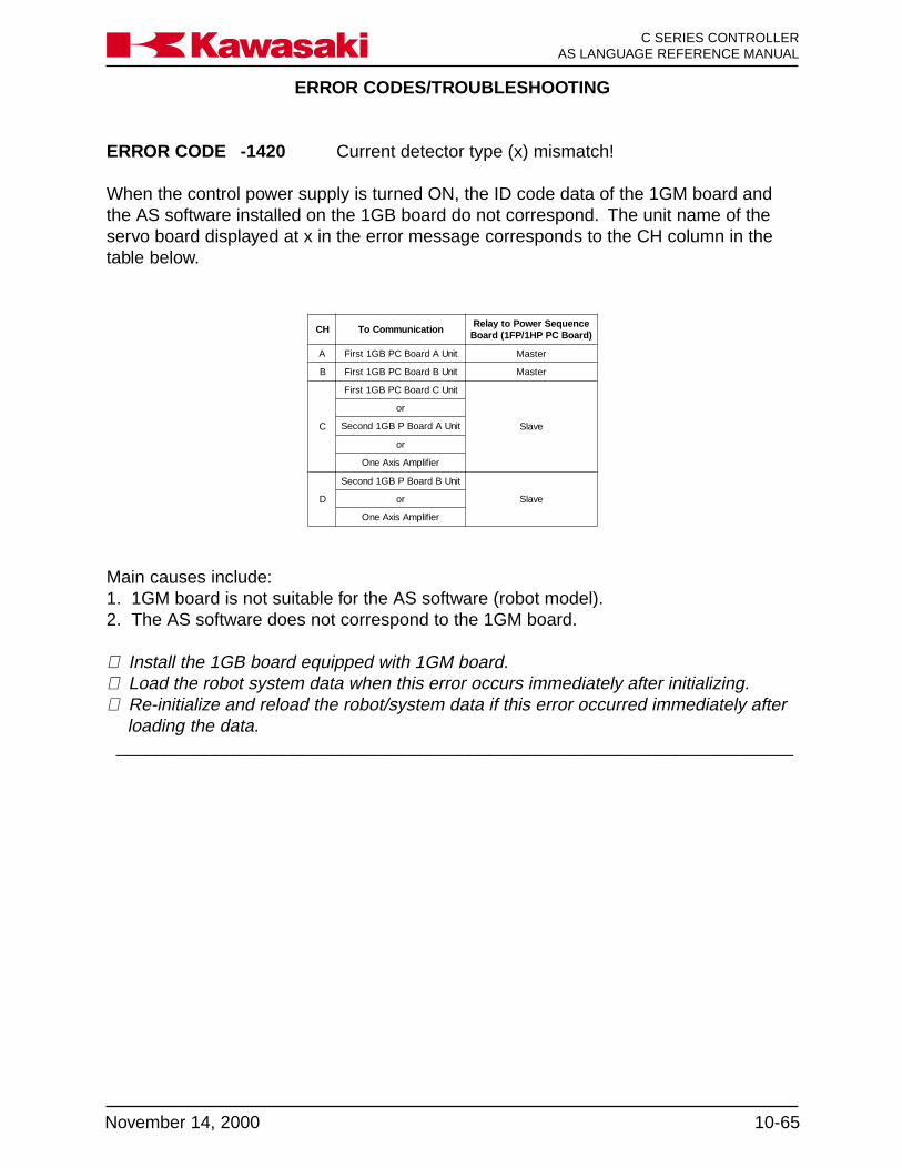
ERROR CODES/TROUBLESHOOTING
10-65November 14, 2000
C SERIES CONTROLLERAS LANGUAGE REFERENCE MANUALKa a aw s k
ERROR CODE -1420 Current detector type (x) mismatch!
When the control power supply is turned ON, the ID code data of the 1GM board andthe AS software installed on the 1GB board do not correspond. The unit name of theservo board displayed at x in the error message corresponds to the CH column in thetable below.
HC noitacinummoCoTecneuqeSrewoPotyaleR)draoBCPPH1/PF1(draoB
A tinUAdraoBCPBG1tsriF retsaM
B tinUBdraoBCPBG1tsriF retsaM
C
tinUCdraoBCPBG1tsriF
evalS
ro
tinUAdraoBPBG1dnoceS
ro
reifilpmAsixAenO
D
tinUBdraoBPBG1dnoceS
evalSro
reifilpmAsixAenO
Main causes include:1. 1GM board is not suitable for the AS software (robot model).2. The AS software does not correspond to the 1GM board.
⇒ Install the 1GB board equipped with 1GM board.⇒ Load the robot system data when this error occurs immediately after initializing.⇒ Re-initialize and reload the robot/system data if this error occurred immediately after
loading the data._____________________________________________________________________

ERROR CODES/TROUBLESHOOTING
C SERIES CONTROLLERAS LANGUAGE REFERENCE MANUAL
10-66 November 14, 2000
Ka a aw s k
ERROR CODE -1500 Motor overload jt-x.
Spot welding and material handlingThe current feedback from the power block exceeded maximum continuous ratingslonger than the time allowed. Main causes include:Mechanical -1. The robot arm has contacted an external item hindering movement.2. The harness is caught in the robot arm.3. The decelerator, the gear, or the bearing are damaged.4. Gear decelerator backlash is too narrow.5. Payload weight exceeds robot specifications for capacity.6. Robot motion pattern exceeds ratings of the motor.7. Motor brake is not released.Electrical-1. Motor power line U, V, and W phase are disconnected.
(1GC↔power block↔X4/X5↔robot)2. The brake line is disconnected or brake drive circuit is damaged.
(T1↔TB1↔V1↔XHY-CN1↔1HY↔XHY-CN2↔XGB-CN14↔1GB↔XGB-CN6↔X5↔robot)
3. The power block is damaged.4. Defect in the 1HY board.5. Defect in the 1GB servo board.6. Malfunction of the motor.
⇒ Check the decelerator, etc. for mechanical failure. Replace as necessary.⇒ Re-teach the robot motion as necessary.⇒ Check the harness and servo unit for electrical malfunctions and replace if necessary.
Servo welding gun1. Clamping pressure time is excessive.2. Distance between weld points is short; the motor does not have time to cool suffi-
ciently between welds.3. Clamping pressure setting exceeds the servo gun motor power capacity.
⇒ If the weld points are close to each other, set a time delay. This provides a cool-downperiod for the servo gun motor.
⇒ Set the clamping force lower (see servo gun manufacturer’s specifications)._____________________________________________________________________

ERROR CODES/TROUBLESHOOTING
10-67November 14, 2000
C SERIES CONTROLLERAS LANGUAGE REFERENCE MANUALKa a aw s k
ERROR CODE -1501 Overheat or motor harness is disconnected (x).
Motor thermal circuit is open due to motor overheat or harness problem. Not all robotmodels utilize thermal switches in the motors. The unit name of the servo board dis-played at x in the error message corresponds to the CH column in the table below.
HC noitacinummoCoTecneuqeSrewoPotyaleR)draoBCPPH1/PF1(draoB
A tinUAdraoBCPBG1tsriF retsaM
B tinUBdraoBCPBG1tsriF retsaM
C
tinUCdraoBCPBG1tsriF
evalS
ro
tinUAdraoBPBG1dnoceS
ro
reifilpmAsixAenO
D
tinUBdraoBPBG1dnoceS
evalSro
reifilpmAsixAenO
Main causes include:1. Disconnected thermal line.
(1GB↔XGB-CN6↔XTH↔X4↔robot)2. Defective connection in the separation harness.3. Defect in the servo board.4. When the thermal is built-in:
The robot rated weight capacity is exceeded.The ambient temperature exceeds limits for use.Constant execution of abrupt high speed direction changes.Defect robot cooling fan or cooling air purge system.Servo system holding the robot arm in high load position for extended periods.Defect in the thermal switch.
⇒ When the thermal switch opens, error cannot be reset until cooling is complete.⇒ Confirm continuity of thermal line.⇒ Replace the harness or servo board as necessary.⇒ Use the auto servo off function, AUX 91, to prevent the servo system holding a high
load arm position for extended periods._____________________________________________________________________

ERROR CODES/TROUBLESHOOTING
C SERIES CONTROLLERAS LANGUAGE REFERENCE MANUAL
10-68 November 14, 2000
Ka a aw s k
ERROR CODE -1503 Speed error jt-x.
Joint speed calculated with encoder value exceeded a regulated value. In the Repeatmode: the rated joint speed * 1.2. In the Teach/Check modes: 250mm/sec. * 1.5, at theequivalent radius position for a rotating joint or actual command value speed for a linearjoint. This error is caused by the following abnormalities:1. Disconnected motor power line U, V, and W phase, and defective power block.2. Wiring error in motor power line and encoder line.3. Disconnected encoder single line, short circuit and defective main body of encoder.4. Robot dependent upon singularity motion.5. Defect in the 1GB servo board and 1GB power block.6. Moment of inertia exceeded the motor torque.
⇒ Check for disconnection, short circuit, and proper wiring. Replace the harness andencoder if necessary.
⇒ Replace the servo unit.⇒ Rewrite program teach data such as speed and position in the case of singularity
motion._____________________________________________________________________
ERROR CODES/TROUBLESHOOTING
10-69November 14, 2000
C SERIES CONTROLLERAS LANGUAGE REFERENCE MANUALKa a aw s k
ERROR CODE -1504 Position envelope error jt-x.
spot welding and material handlingThe difference between the current value from the encoder and the command value inthe AS software exceeded a regulated value which varies by robot model. Main causesinclude singularity motion or the following abnormalities:Mechanical -1. The robot arm has contacted an external item hindering movement.2. The harness is caught in the robot arm.3. The decelerator, the gear, or the bearing are damaged.4. Gear decelerator backlash is too narrow.5. Payload weight exceeds robot specifications for capacity.6. Robot motion pattern exceeds ratings of the motor.7. Motor brake is not released.Electrical-1. Motor power line U, V, and W phase are disconnected.
(1GC↔power block↔X4/X5↔robot)2. The brake line is disconnected or brake drive circuit is damaged.
(T1↔TB1↔V1↔XHY-CN1↔1HY↔XHY-CN2↔XGB-CN14↔1GB↔XGB-CN6↔X5↔robot)
3. The power block is damaged.4. Defect in the servo board.5. Malfunction of the motor.
⇒ Check the decelerator, etc. for mechanical failure. Replace as necessary.⇒ Re-teach robot motion as necessary.⇒ Check the harness and servo unit for electrical malfunctions and replace if necessary.⇒ Correct the teach data in case of singularity motion.
Servo welding gunThe thickness of the workpiece at the weld point is greater than the thickness when thepoint was taught. The thickness difference needed to set this error is approximately10mm, depending on the gun type.
⇒ Inspect the workpiece; replace it if necessary._____________________________________________________________________

ERROR CODES/TROUBLESHOOTING
C SERIES CONTROLLERAS LANGUAGE REFERENCE MANUAL
10-70 November 14, 2000
Ka a aw s k
ERROR CODE -1505 Velocity envelope error jt-x.
The robot’s current velocity is unable to keep up with the velocity command signal.
⇒ Refer to Error Code -1504: Position envelope error jt-x_____________________________________________________________________
ERROR CODE -1506 Commanded speed error jt-x.
Unused._____________________________________________________________________
ERROR CODE -1507 Commanded acceleration error jt-x.
Unused._____________________________________________________________________
ERROR CODE -1510 Encoder harness broken jt-x.
The encoder signal is lost.
⇒ Machine signal or separate signal harness⇒ +12 VDC or +5 VDC at the 1FG board⇒ 1GB or 1FG board
_____________________________________________________________________
ERROR CODES/TROUBLESHOOTING
10-71November 14, 2000
C SERIES CONTROLLERAS LANGUAGE REFERENCE MANUALKa a aw s k
ERROR CODE -1511 Encoder battery voltage low [Servo (A)].
Voltage of the encoder back up battery on the 1FG board decreased to 3.2 volts, or theencoder battery alarm signal (BAL_AL) was disconnected. This error is only detected atcontrol power on or motor power on. This is caused by the following:1. Discharged batteries.2. Defective encoder battery board (1FG board).3. Defective encoder.4. Short in the harness from the encoder battery backup board to the encoder.5. Battery discharge.6. Defective servo board (1GB board).
This error is reported by servo board unit A.
⇒ Exchange the battery. There is a possibility that internal encoder data may be lost.Check the robot zeroing.
⇒ Check each harness for short circuit.⇒ Replace the encoder, the servo board, or the encoder battery backup board, if neces-
sary._____________________________________________________________________
ERROR CODE -1513 Encoder rotation data abnormal jt-x.
Occurs when there is a difference between the rotation data in the serial encoder dataand the calculated rotation data by incremental technique.
⇒ Check connections at encoder, 1FG board, and separation harness.⇒ Check for noise and shield integrity.⇒ Check connections, jumpers, and switches on 1GB board.⇒ Check for continuity in the machine harness and separation harness.⇒ Replace 1FG board.⇒ Replace the 1GB board.⇒ Replace the encoder._____________________________________________________________________

ERROR CODES/TROUBLESHOOTING
C SERIES CONTROLLERAS LANGUAGE REFERENCE MANUAL
10-72 November 14, 2000
Ka a aw s k
ERROR CODE -1516 Encoder data abnormal jt-x.
When control power is switched ON, the current encoder value is compared to thestored encoder value when the power was turned OFF. If the difference is more than thevalue set by AUX 43, Encoder Error Range, or the ENCCHK_DATA command, this erroroccurs. Normal occurrence is due to the following:1. Back up battery failure due to disconnection or discharged battery.2. Control power was turned off during robot motion by an abnormal power supply, etc.,
causing the robot to stop in a position other than the last position memorized by theAS software.
3. Motor replacement/encoder replacement.4. Robot arm or motor operated by force when control power was off.5. Robot was initialized.
⇒ Data may have been lost due to backup battery. See error -1511. Exchange thebattery. There is a possibility that internal encoder data may be lost. Check the robotzeroing.
⇒ Check each harness for short circuit.⇒ Replace the encoder, the servo board or the encoder battery backup board if neces-
sary._____________________________________________________________________
ERROR CODE -1517 Cannot read initial data encoder jt-x.
Spot welding and material handlingImmediately after control power on, steady encoder data was not able to be read. Thiserror is caused by a disconnected encoder signal line or a short circuit, or a defect in themain body of the encoder.
⇒ Check for disconnection or short circuit for encoder signal line.⇒ Replace the encoder.⇒ Replace the servo board (1GB board).
Servo welding gunThe gun is disconnected from the tool changer, without performing a software discon-nect.
⇒ Connect the gun manually and cycle the controller power (OFF/ON)._____________________________________________________________________
ERROR CODES/TROUBLESHOOTING
10-73November 14, 2000
C SERIES CONTROLLERAS LANGUAGE REFERENCE MANUALKa a aw s k
ERROR CODE -1518 Miscount of encoder data jt*.
The servo gun or tool changer harness is defective.
⇒ Inspect the servo gun and tool changer harnesses; replace if necessary._____________________________________________________________________
ERROR CODE -1521 Mismatch ABS and INC encoder of jt-x.
Occurs when there is a large difference between the value in the serial encoder dataand the data calculated by incremental technique.
⇒ Replace encoder, replace 1GB board.⇒ Check connections at encoder, 1FG board, and separation harness.⇒ Check connections, jumpers, and switches on 1GB board.⇒ Check for continuity in the machine harness and separation harness.⇒ Replace 1FG board._____________________________________________________________________
ERROR CODE -1524 Encoder line error of jt-x.
Not used._____________________________________________________________________
ERROR CODE -1550 Encoder initialize error jt-x.
The encoder is not able to fix the absolute position at control power on. The scanning ofabsolute data is begun immediately after a shift from the state of non-operation or back-up operation to normal encoder operation. BUSY=1 is output until the absolute positionhas been determined.
⇒ In the case of a conveyor encoder, ensure power-up speed is below 300 RPM.⇒ Check connections at encoder, 1FG board, jumpers, and switches on 1GB board. ⇒Replace encoder, replace 1GB board, replace 1FG board.⇒ Check for continuity in the machine harness and separation harness._____________________________________________________________________

ERROR CODES/TROUBLESHOOTING
C SERIES CONTROLLERAS LANGUAGE REFERENCE MANUAL
10-74 November 14, 2000
Ka a aw s k
ERROR CODE -1553 Encoder response error jt-x.
Spot welding and material handlingOccurs when the encoder does not respond to data request signal from the 1GB board.
⇒ Check connections at encoder, 1FG board, and separation harness.⇒ Check connections, jumpers, and switches on 1GB board.⇒ Replace encoder, replace 1GB board.⇒ Check for continuity in the machine harness and separation harness.⇒ Replace 1FG board.⇒ Check for noise malfunction and shield integrity.
Servo welding gunThe servo gun or tool changer harness is defective.
⇒ Inspect the servo gun and tool changer harnesses; replace if necessary._____________________________________________________________________
ERROR CODE -1554 Encoder communication error jt-x.
Occurs when the encoder serial data is not correctly transmitted according to communi-cation protocol.
⇒ Check connections at encoder, 1FG board, and separation harness.⇒ Check connections, jumpers, and switches on 1GB board.⇒ Replace encoder, replace 1GB board.⇒ Check for continuity in the machine harness and separation harness.⇒ Replace 1FG board.
_____________________________________________________________________
ERROR CODE -1555 Encoder data conversion error jt-x.
Occurs when the M-code data from the encoder has an error pattern.
⇒ Replace encoder, replace 1GB board.⇒ Check connections at encoder, 1FG board, and separation harness.⇒ Check connections, jumpers and switches on 1GB board.⇒ Check for continuity in the machine harness and separation harness.⇒ Replace 1FG board.
_____________________________________________________________________

ERROR CODES/TROUBLESHOOTING
10-75November 14, 2000
C SERIES CONTROLLERAS LANGUAGE REFERENCE MANUALKa a aw s k
ERROR CODE -1556 Encoder ABS-track error jt-x.
The absolute data and the incremental data in the encoder are different. ABSALM=1 isoutput from the encoder when this error occurs.
⇒ Defective encoder.⇒ Defective 1GB or 1FG boards.⇒ Open or short-circuited encoder harness._____________________________________________________________________
ERROR CODE -1557 Encoder INC-pulse error jt-x.
Occurs when the encoder A and B incremental pulses are abnormal. The encoderINALM bit sent with the serial data=1.
⇒ Replace encoder, replace 1GB board.⇒ Check connections at encoder, 1FG board, and separation harness.⇒ Check connections, jumpers, and switches on 1GB board.⇒ Check for continuity in the machine harness and separation harness.⇒ Replace 1FG board._____________________________________________________________________
ERROR CODE -1558 Encoder MR-sensor error jt-x.
The state of the MR sensor in the encoder does not match with JT ENCODER in onerotation.
⇒ Replace the encoder harness._____________________________________________________________________
ERROR CODE -1559 Power module error jt-x.
An error signal from the IPM module in the power block was detected. This error may becaused by:1. Defect in the power block.2. Defect in the servo board.3. Short-circuit of the motor power line U, V, and W phase.4. Defective cooling fan in the servo unit.5. Defect in the harness between the servo board and the power blocks.
(XGB-CN12↔XGC/XGD-CN8, XGB-CN13↔XGC/XGD-CN9)
⇒ Replace the servo unit.⇒ Check for short circuit in the motor harness and replace if necessary._____________________________________________________________________
ERROR CODES/TROUBLESHOOTING
C SERIES CONTROLLERAS LANGUAGE REFERENCE MANUAL
10-76 November 14, 2000
Ka a aw s k
ERROR CODE -1561 Current sensor disconnect [Servo (x)].
The current sensor cable between the servo board and the power blocks is not con-nected. The x indicates the servo board unit reporting the error. Check the followingharnesses as indicated below.
Unit A - 1GB-CN9↔power block CN1, CN2 CN3.Unit B - 1GB-CN10↔power block CN4, CN5, CN6.Unit C - 1GB-CN11↔power block CN7.This error may be caused by a defect in the 1GB board.
⇒ Check connection and continuity in the current sensor cable between the 1GB boardand the power block. (XGB-CN9↔XGB-CN10)
⇒ Replace the 1GB board if necessary._____________________________________________________________________
ERROR CODE -1563 Servo unit 12V DC error [Servo (A)].
The +/-12V supply to the 1GB board is below specified limits of +10.75V and -10.4V.This error may be caused by a defect in the harness between the 1GB board (XGB-CN8), the mother board (XHZ-CN2) and the AVR, or a defect in the 1GB board. Thiserror is reported by servo board unit A.
⇒ Check the voltage and replace the 1GB board and the AVR as necessary._____________________________________________________________________
ERROR CODE -1567 Regenerative resistor error [Servo (A)].
Current was sent to regenerative resistors for six or more consecutive seconds. Maincauses include:1. Abrupt direction changes at high speed.2. Burned out resistors or defective power block.3. Defect in the servo board (1GB board).4. Defective connection or harness between the servo board and the power block
(1GB-CN13 ⇔ power block CN9).5. Defect in the optional second regenerative resistance unit (when used).
This error is reported by servo board unit A.
⇒ Avoid abrupt high speed direction changes. Change accuracy, speed, add points.⇒ Install optional second regenerative resistance unit.
_____________________________________________________________________
ERROR CODES/TROUBLESHOOTING
10-77November 14, 2000
C SERIES CONTROLLERAS LANGUAGE REFERENCE MANUALKa a aw s k
ERROR CODE -1568 Servo unit P-N low voltage [Servo (A)].
The voltage between P-N supplied to the power block is 60VDC or less at servo on.Main causes include:1. Defect of K1, K2, K3.2. Defect in the relay board (1FY/1HY board).3. Defect in the power sequence board (1FP/1HP board).4. Defect in the power unit.5. Defect in the servo board.6. Defect in the motor power circuit (diode bridge, K3, etc).7. Defect in circuit breaker F2 or F2 is in the OFF position.8. Defect in the harness between the operation unit and the servo units or the connec-
tions.
⇒ Check the motor power circuit and the equipment, replace as necessary.⇒ Check the power sequence board, the relay board ,and the servo unit, and replace as
necessary._____________________________________________________________________
ERROR CODE -1569 Servo unit P-N- high voltage [Servo (A)].
The voltage between P-N supplied to the power block exceeded 410 VDC. This error iscaused by:1. Defect in regenerative resistance control circuit, overheat failure of regenerative
resistance unit, defect in the voltage monitoring circuit, or defect in the power block.2. Defect of servo board (1GB board)3. Defect in the regenerative resistance unit.4. Defect in the servo board (1GB board).5. High inertia loads due to tool weight or program data.
This error is reported by servo board unit A.
⇒ Reteach program steps to eliminate sudden high speed direction changes (dynamicshock).
⇒ Replace the servo unit and the regenerative unit.⇒ Add the second regenerative resistor unit._____________________________________________________________________

ERROR CODES/TROUBLESHOOTING
C SERIES CONTROLLERAS LANGUAGE REFERENCE MANUAL
10-78 November 14, 2000
Ka a aw s k
ERROR CODE -1570 Regenerative resistor over-heat [Servo (A)] or controllerhot.
The thermal switch for the power block regenerative resistor unit, or the optional regen-erative resistor unit reached 140° C (284°F), or the heat sink thermal switch reached90°C (194°F), or the controller cabinet thermal switch reached 70° C (158° F). Thiserror is reported by servo board unit A.
⇒ Defective cooling fans.⇒ Insufficient clearance for air circulation.⇒ Power block connecter X5-SA disconnected, or defect in the wiring harness to the
controller cabinet thermal switch, or to the optional regenerative resistor unit.⇒ High inertia loads.⇒ High ambient controller temperature.⇒ Defective power block.⇒ Defective regenerating resistor unit.⇒ Defective 1GB board.⇒ Defect in the following harnesses: 1GB-CN13↔power block CN9,
1GC-CN21↔optional regenerative resistor unit._____________________________________________________________________
ERROR CODES/TROUBLESHOOTING
10-79November 14, 2000
C SERIES CONTROLLERAS LANGUAGE REFERENCE MANUALKa a aw s k
ERROR CODE -1600 Uncoincidence error jt-x.
During the execution of a program, all joints must reach total coincidence within a givenaccuracy and time (approx. 5 seconds) This error occurs if the difference between thedesignated value and current value exceeds the established accuracy. Typical causesare listed below.Mechanical-1. Damaged bearings.2. Insufficient gear backlash.3. Motor brake not released.4. Arm movement restricted by harnesses or peripheral devices.Electrical-1. Defective servo board (1GB board).2. Defective power block.3. Disconnected motor power or brake lines.4. Defective encoder or encoder harness.Program data-1. Wrist positions at the beginning and end of a path that utilize the same XYZ coordi-
nate.
⇒ Repair mechanical or electrical failures.⇒ Check interference from external devices.⇒ Modify taught wrist positions as required._____________________________________________________________________
ERROR CODE -1601 Limit switch of joint-x is ON.
This error occurs when the software can specify the axis that has caused the over travelcondition. If the joint number cannot be specified, ERROR CODE 1602 Limit switch isbroken, is displayed. Main causes include:1. Software limits are set incorrectly.2. Axis was moved using the manual brake release and the limit switch was turned ON.3. The limit switch was turned ON by overshoot from inertia.
⇒ Check and exchange the harness and the limit switch.⇒ Set the software limits to an appropriate value.⇒ Change the installation angle of the axis restriction limit switch to an appropriate
value.⇒ Replace the power sequence board if necessary._____________________________________________________________________

ERROR CODES/TROUBLESHOOTING
C SERIES CONTROLLERAS LANGUAGE REFERENCE MANUAL
10-80 November 14, 2000
Ka a aw s k
ERROR CODE -1602 Limit switch signal line is broken.
This error occurs when the software cannot specify the axis that has caused the overtravel condition. If the joint number can be identified, the “ERROR CODE 1601 Limitswitch of jt-x is ON.”
⇒ Set the software limits to an appropriate value.⇒ Change the installation angle of the axis restriction limit switch to an appropriate
value.⇒ Check harness and limit switch and replace as necessary.⇒ Check the power sequence board and replace if necessary.
_____________________________________________________________________
ERROR CODE -1610 Torch is interfered.
The limit switch for torch interference detection has been tripped.
⇒ Move the robot away from the interference to close the limit switch. Inspect the torchfor damage.
⇒ Determine the cause of the interference before continuing operation._____________________________________________________________________
ERROR CODE -1735 GROUP is not primed.
The GROUP instruction is not programmed before a motion instruction, with externalaxis system.
⇒ This error occurs if the program is interrupted after a GROUP instruction and beforethe motion commands pertaining to the GROUP instruction are complete. Whenrestarting the program prime the program before the GROUP instruction.
⇒ In check mode, if the GROUP instruction is used, start checking before the GROUPinstruction.
_____________________________________________________________________

ERROR CODES/TROUBLESHOOTING
10-81November 14, 2000
C SERIES CONTROLLERAS LANGUAGE REFERENCE MANUALKa a aw s k
ERROR CODE -1800 AC primary power off.
This error occurs when there is an instantaneous decrease in the primary power to theAVR for control power supply (AC130-145V or less for 20-30 msec from 0 phase). Themain causes for this error are:1. NFB for the control power supply was turned OFF.2. AC200/220V supplied to AVR for the control power supply caused the instantaneous
decrease.3. Defective AVR for control power supply.4. Defective NFB for control power supply or NFB tripped.5. Defect in the primary power supply.6. Defective power sequence board.7. Defect in the relay board.
⇒ It is normal for this error to occur when NFB for control power supply is turned OFF.⇒ Check power supply circuit in AVR for the control power supply and NFB.⇒ Confirm that primary power is supplied according to specifications._____________________________________________________________________
ERROR CODE -1801 24VDC power source is low.
24VDC to the power sequence board has dropped below 21.6V. Main causes includethe following abnormalities:1. Defect in the AVR for control power supply.2. Defect in the power sequence board.3. Defect in the relay board.4. Short circuit in the motor power on circuitry, the EMERGENCY STOP switch and axis
restriction limit switch circuits.5. Short in machine valve and sensor circuits.
⇒ Check the power supply, machine valve, and the sensor circuits for short circuits.⇒ Check the AVR, the power sequence board, and the relay board and replace as
necessary._____________________________________________________________________
ERROR CODES/TROUBLESHOOTING
C SERIES CONTROLLERAS LANGUAGE REFERENCE MANUAL
10-82 November 14, 2000
Ka a aw s k
ERROR CODE -1802 Primary power source is high.
Voltage level of the AVR for the control power supply was too high (AC2667-277V ormore for 1-2 sec.). The main causes of this error include a defect in the AVR, the powersequence board, the relay board or the power supply circuit.
⇒ Verify the power supply to the controller are within ratings.⇒ Check power supply circuit to the AVR.⇒ Confirm the supply power is within specifications.⇒ Confirm transformer tap settings are correct.
_____________________________________________________________________
ERROR CODE -1803 Primary power source is low.
Voltage level of the AVR for the control power supply was too low (AC150-158V or lessfor 1-2 sec.). The main causes of this error include an instantaneous drop in the powersupply; a defect in the AVR or NFB, the power sequence board, the relay board or thepower supply circuit.
⇒ Verify the power supply to the controller is within ratings.⇒ Check the AVR and NFB.⇒ Confirm supply power is within specifications.⇒ Confirm transformer tap settings are correct.
_____________________________________________________________________
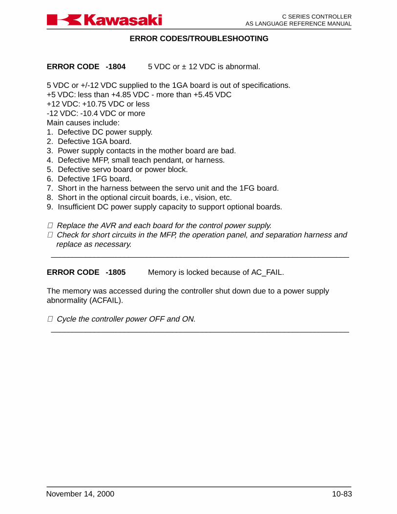
ERROR CODES/TROUBLESHOOTING
10-83November 14, 2000
C SERIES CONTROLLERAS LANGUAGE REFERENCE MANUALKa a aw s k
ERROR CODE -1804 5 VDC or ± 12 VDC is abnormal.
5 VDC or +/-12 VDC supplied to the 1GA board is out of specifications.+5 VDC: less than +4.85 VDC - more than +5.45 VDC+12 VDC: +10.75 VDC or less-12 VDC: -10.4 VDC or moreMain causes include:1. Defective DC power supply.2. Defective 1GA board.3. Power supply contacts in the mother board are bad.4. Defective MFP, small teach pendant, or harness.5. Defective servo board or power block.6. Defective 1FG board.7. Short in the harness between the servo unit and the 1FG board.8. Short in the optional circuit boards, i.e., vision, etc.9. Insufficient DC power supply capacity to support optional boards.
⇒ Replace the AVR and each board for the control power supply.⇒ Check for short circuits in the MFP, the operation panel, and separation harness and
replace as necessary._____________________________________________________________________
ERROR CODE -1805 Memory is locked because of AC_FAIL.
The memory was accessed during the controller shut down due to a power supplyabnormality (ACFAIL).
⇒ Cycle the controller power OFF and ON._____________________________________________________________________

ERROR CODES/TROUBLESHOOTING
C SERIES CONTROLLERAS LANGUAGE REFERENCE MANUAL
10-84 November 14, 2000
Ka a aw s k
10.3 TROUBLESHOOTING FLOWCHARTS
The following flowcharts are arranged in the numerical order of the error code. Referalso to the corresponding error code information in section 10.2 during troubleshootingprocedures.

ERROR CODES/TROUBLESHOOTING
10-85November 14, 2000
C SERIES CONTROLLERAS LANGUAGE REFERENCE MANUALKa a aw s k
Error 1513
END
No
Check connections at theencoder connector
Check connections on the1FG board
Check connections in theseparation harness
Check connections, jumpers, andswitches on the 1GB board
Replace encoder
Doesproblem stil l
exist?
A
Replace 1GB board
No
Yes
Doesproblem stil l
exist?
No
Yes
Yes
Does thiserror occur just
after resetting error1553, 1554, or
1555?
YesFollow
troubleshootingflowchart for each
error
END
Figure 10-3 Error 1513 Flowchart (1)

ERROR CODES/TROUBLESHOOTING
C SERIES CONTROLLERAS LANGUAGE REFERENCE MANUAL
10-86 November 14, 2000
Ka a aw s k
Service call
A
Replace 1FG board
Doesproblem stil l
exist?END
No
Yes
Doesproblem stil l
exist?END
No
Yes
Doesproblem stil l
exist?END
No
Yes
Check insidemachine harness
and separationharness
Figure 10-4 Error 1513 Flowchart (2)

ERROR CODES/TROUBLESHOOTING
10-87November 14, 2000
C SERIES CONTROLLERAS LANGUAGE REFERENCE MANUALKa a aw s k
Error 1521
No
Check connections at theencoder connector
Check connections on the1FG board
Check connections in theseparation harness
Check connections, jumpers, andswitches on the 1GB board
Replace encoder
Doesproblem stil l
exist?
A
Replace 1GB board
Yes
Doesproblem stil l
exist?
No
Yes
Yes
END
Does thiserror occur just
after resetting error1553, 1554, or
1555?
YesFollow
troubleshootingflowchart for each
error
NoEND
Figure 10-5 Error 1521 Flowchart (1)
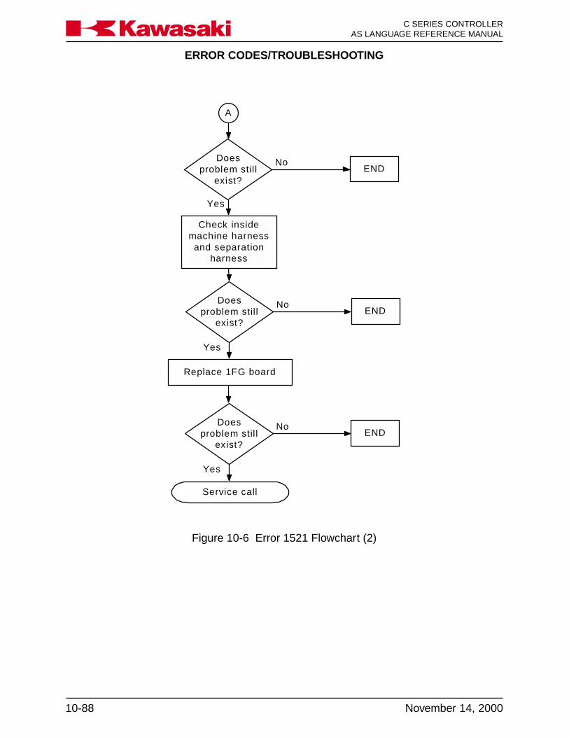
ERROR CODES/TROUBLESHOOTING
C SERIES CONTROLLERAS LANGUAGE REFERENCE MANUAL
10-88 November 14, 2000
Ka a aw s k
Service call
A
Replace 1FG board
Doesproblem stil l
exist?END
No
Yes
Doesproblem stil l
exist?END
No
Yes
Doesproblem stil l
exist?END
No
Yes
Check insidemachine harness
and separationharness
Figure 10-6 Error 1521 Flowchart (2)

ERROR CODES/TROUBLESHOOTING
10-89November 14, 2000
C SERIES CONTROLLERAS LANGUAGE REFERENCE MANUALKa a aw s k
Error 1550
Does theencoder revolve over
300 RPM? (Case of conveyor
encoder)
Check connections at theencoder connector
Doesproblem stil l
exist?END
Reduce conveyorencoder revolutionspeed under 300RPM at power-up
No
Check connections on the1FG board
Check connections in theseparation harness
Check connections, jumpers, andswitches on the 1GB board
No
Yes
Replace encoder
Doesproblem stil l
exist?END
No
Yes
A
END
Yes
Figure 10-7 Error 1550 Flowchart (1)

ERROR CODES/TROUBLESHOOTING
C SERIES CONTROLLERAS LANGUAGE REFERENCE MANUAL
10-90 November 14, 2000
Ka a aw s k
Replace 1FG board
Service call
A
Check machineharness and
separation harness
Replace 1GB board
Doesproblem stil l
exist?END
No
Yes
Doesproblem stil l
exist?END
No
Yes
Doesproblem stil l
exist?END
No
Yes
Figure 10-8 Error 1550 Flowchart (2)

ERROR CODES/TROUBLESHOOTING
10-91November 14, 2000
C SERIES CONTROLLERAS LANGUAGE REFERENCE MANUALKa a aw s k
Error 1553
Can you resetthe error?
Check connections at theencoder connector
Doesproblem stil l
exist?END
Retry robotprogram execution
or manualoperation carefully
Check connections on the1FG board
Check connections in theseparation harness
Check connections, jumpers, andswitches on the 1GB board
No
Yes
Replace encoder
Doesproblem stil l
exist?END
No
Yes
A
END
Yes
Does the errorreoccur?
No
No
Yes
Figure 10-9 Error 1553 Flowchart (1)

ERROR CODES/TROUBLESHOOTING
C SERIES CONTROLLERAS LANGUAGE REFERENCE MANUAL
10-92 November 14, 2000
Ka a aw s k
Service call
A
Replace 1GB board
Doesproblem stil l
exist?END
No
Yes
Doesproblem stil l
exist?END
No
Yes
Replace 1FG board
Doesproblem stil l
exist?END
No
Yes
Check machineharness and
separation harness
Figure 10-10 Error 1553 Flowchart (2)

ERROR CODES/TROUBLESHOOTING
10-93November 14, 2000
C SERIES CONTROLLERAS LANGUAGE REFERENCE MANUALKa a aw s k
Error 1554
Can you resetthe error?
Check connections at theencoder connector
Doesproblem stil l
exist?END
Retry robotprogram execution
or manualoperation carefully
Check connections on the1FG board
Check connections in theseparation harness
Check connections, jumpers, andswitches on the 1GB board
No
Yes
Replace encoder
Doesproblem stil l
exist?END
No
Yes
A
END
Yes
Does the errorreoccur?
No
No
Yes
Figure 10-11 Error 1554 Flowchart (1)

ERROR CODES/TROUBLESHOOTING
C SERIES CONTROLLERAS LANGUAGE REFERENCE MANUAL
10-94 November 14, 2000
Ka a aw s k
Service call
A
Replace 1GB board
Doesproblem stil l
exist?END
No
Yes
Doesproblem stil l
exist?END
No
Yes
Replace 1FG board
Doesproblem stil l
exist?END
No
Yes
Check machineharness and
separation harness
Figure 10-12 Error 1554 Flowchart (2)
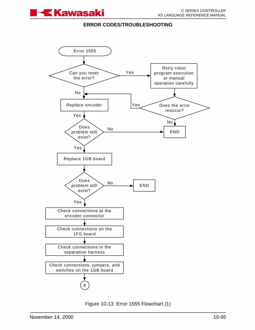
ERROR CODES/TROUBLESHOOTING
10-95November 14, 2000
C SERIES CONTROLLERAS LANGUAGE REFERENCE MANUALKa a aw s k
Error 1555
Can you resetthe error?
Retry robotprogram execution
or manualoperation carefully
END
Yes
Does the errorreoccur?
No
No
Yes
Check connections at theencoder connector
Check connections on the1FG board
Check connections in theseparation harness
Check connections, jumpers, andswitches on the 1GB board
Replace encoder
Doesproblem stil l
exist?
A
Replace 1GB board
No
Yes
Doesproblem stil l
exist?
No
Yes
Yes
END
Figure 10-13 Error 1555 Flowchart (1)

ERROR CODES/TROUBLESHOOTING
C SERIES CONTROLLERAS LANGUAGE REFERENCE MANUAL
10-96 November 14, 2000
Ka a aw s k
Service call
A
Replace 1FG board
Doesproblem stil l
exist?END
No
Yes
Doesproblem stil l
exist?END
No
Yes
Doesproblem stil l
exist?END
No
Yes
Check insidemachine harness
and separationharness
Figure 10-14 Error 1555 Flowchart (2)

ERROR CODES/TROUBLESHOOTING
10-97November 14, 2000
C SERIES CONTROLLERAS LANGUAGE REFERENCE MANUALKa a aw s k
Error 1556
END
Check connections at theencoder connector
Check connections on the1FG board
Check connections in theseparation harness
Check connections, jumpers, andswitches on the 1GB board
Replace encoder
Doesproblem stil l
exist?
A
Replace 1GB board
No
Yes
Doesproblem stil l
exist?
No
Yes
END
Doesproblem stil l
exist?
No
Yes
END
Figure 10-15 Error 1556 Flowchart (1)
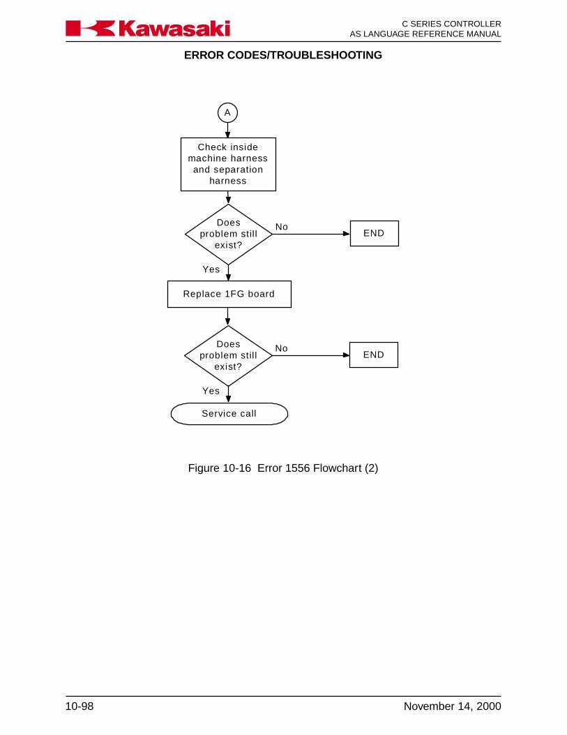
ERROR CODES/TROUBLESHOOTING
C SERIES CONTROLLERAS LANGUAGE REFERENCE MANUAL
10-98 November 14, 2000
Ka a aw s k
Service call
A
Replace 1FG board
Doesproblem stil l
exist?END
No
Yes
Doesproblem stil l
exist?END
No
Yes
Check insidemachine harness
and separationharness
Figure 10-16 Error 1556 Flowchart (2)
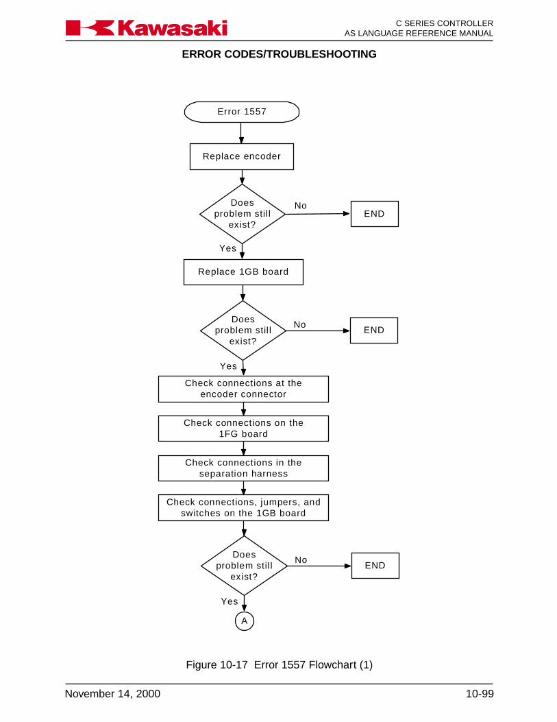
ERROR CODES/TROUBLESHOOTING
10-99November 14, 2000
C SERIES CONTROLLERAS LANGUAGE REFERENCE MANUALKa a aw s k
Error 1557
Check connections at theencoder connector
Check connections on the1FG board
Check connections in theseparation harness
Check connections, jumpers, andswitches on the 1GB board
Replace encoder
Doesproblem stil l
exist?
A
Replace 1GB board
Yes
Doesproblem stil l
exist?
No
Yes
END
Doesproblem stil l
exist?
No
Yes
END
ENDNo
Figure 10-17 Error 1557 Flowchart (1)
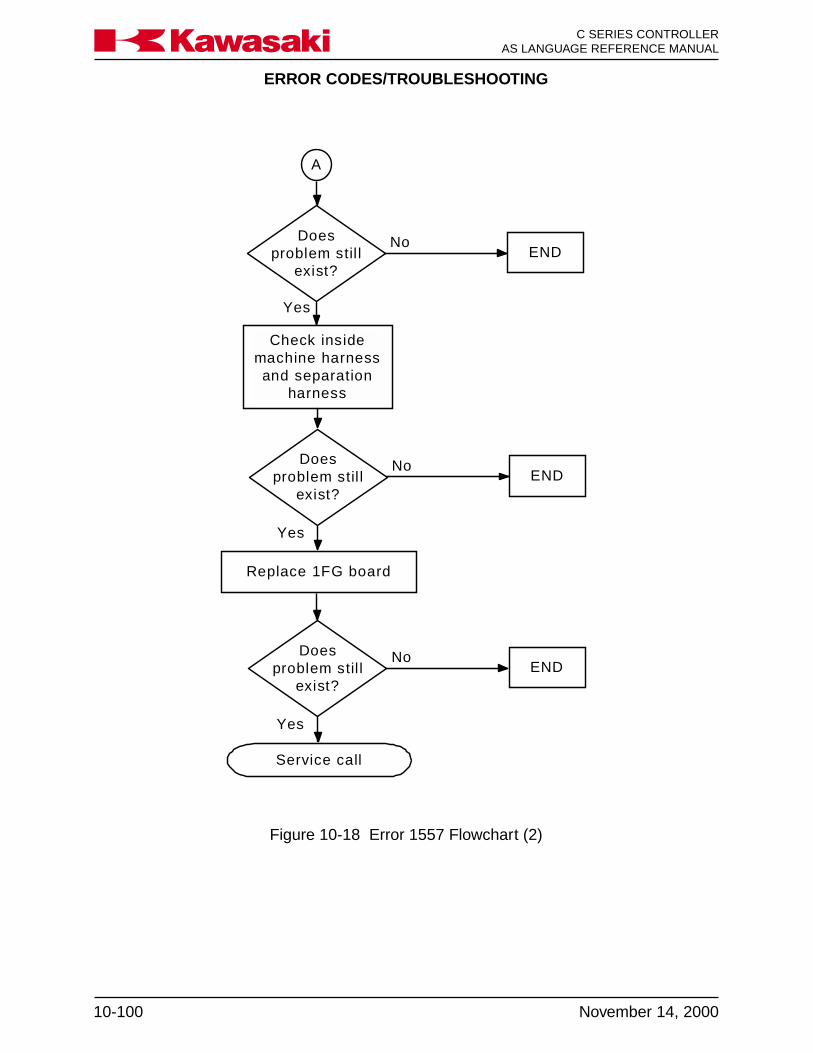
ERROR CODES/TROUBLESHOOTING
C SERIES CONTROLLERAS LANGUAGE REFERENCE MANUAL
10-100 November 14, 2000
Ka a aw s k
Service call
A
Replace 1FG board
Doesproblem stil l
exist?END
No
Yes
Doesproblem stil l
exist?END
No
Yes
Doesproblem stil l
exist?END
No
Yes
Check insidemachine harnessand separation
harness
Figure 10-18 Error 1557 Flowchart (2)

APPENDIX
A-1November 14, 2000
Ka a aw s k C SERIES CONTROLLERAS LANGUAGE REFERENCE MANUAL
A.0 APPENDIX ..................................................................................................... A-2A.1 Remote I/O and ControlNet ............................................................................ A-2A.1.1 SLOGIC .......................................................................................................... A-2A.1.1.1 Slogic Program ............................................................................................... A-2A.1.1.2 SCNT Command ............................................................................................ A-6A.1.1.3 SFLK Command ............................................................................................. A-6A.1.1.4 SFLP Command ............................................................................................. A-6A.1.1.5 STIM Command.............................................................................................. A-7A.1.1.6 RI/O Monitor, Aux 180 .................................................................................... A-7A.1.1.7 RI/O PLC (NAC) Setting, Aux 181 ................................................................ A-12A.1.2 ControlNet..................................................................................................... A-13A.2 Motion Control and Location Definition ......................................................... A-16A.2.1 C1MOVE and C2MOVE Commands ............................................................ A-16A.2.2 FMOVE command ........................................................................................ A-18A.2.3 MVWAIT Command ...................................................................................... A-21A.2.4 BSPEED Command...................................................................................... A-22A.2.5 TRHERE Command ..................................................................................... A-22A.3 System Parameters and Switches ................................................................ A-23A.3.1 NCHON and NCHOFF Commands .............................................................. A-23A.3.2 WEIGHT Command ...................................................................................... A-23A.3.3 MC Command............................................................................................... A-23A.3.4 AUTOSTART.PC Switches ............................................................................ A-23A.3.5 ERRSTART.PC Switch .................................................................................. A-23A.3.6 AFTER.WAIT.TMR Switch ............................................................................ A-24A.4 Function Commands..................................................................................... A-24A.4.1 DEXT Function ............................................................................................. A-24A.4.2 PRIORITY Function ...................................................................................... A-24A.4.3 PCSCAN Command ..................................................................................... A-24A.5 Process Control Commands ......................................................................... A-25A.5.1 PCSTATUS Command .................................................................................. A-25A.5.2 PC Program Control ..................................................................................... A-26A.6 American Standard Code for Information Interchange Set ........................... A-28A.7 KeyWords List ............................................................................................... A-31

APPENDIX
C SERIES CONTROLLERAS LANGUAGE REFERENCE MANUAL
A-2 November 14, 2000
Ka a aw s k
A.0 APPENDIX
A.1 REMOTE I/O AND CONTROLNET
The C-series controller provides the capability to control remote input/output functionsusing SLOGIC programming with two configurations of the 1FS circuit board. Theseconfigurations are the remote input/output (R I/O) and RS-485, and ControlNet. The Ccontroller 1FS board performs functions that are similar to the AD controller 1AS board,but does not provide parallel I/O (PI/O) or analog outputs. These functions are per-formed by the 1GW board.
A.1.1 SLOGIC
Relay circuitry and wiring for the controller interface with peripheral devices is reducedby utilizing the SLOGIC software programming function. SLOGIC programming is simi-lar in theory to the ladder logic programming used with PLCs. Table A-1 shows a com-parison of SLOGIC program instructions and ladder logic. Making signal assignmentsfor remote inputs and outputs using SLOGIC is faster and easier than making changesto discrete hard-wired systems. With discrete hard-wired systems, signal assignmentchanges are made by physically changing the wiring connections.
Using SLOGIC programming, signal assignment changes are made by simply editingthe program. The SOUT command is used to assign a signal expression to a 1FS boardoutput signal number.
SOUT signal_number = signal_expression.
Example: SOUT 1001 = 1 AND 2
SLOGIC output signal 1001 (1GA board input signal WX1) is turned on when 1FS boardinputs 1 and 2 (1GA board output signals 1 and 2) are on.
Figure A-1 shows the signal numbers available for communication with the 1FS board.
SLOGIC program instructions are used to specify outputs, timers, and counters.SLOGIC program instructions are edited on the 1GA board (main CPU) via the multifunction panel and then transferred to the 1FS (R I/O) board, which executes theSLOGIC program.
A.1.1.1 SLOGIC PROGRAM
Naming an SLOGIC program is different from other AS Language programs; the onlyname that is assigned to an SLOGIC program is spg.
To edit an SLOGIC program use the procedure on the next page.

APPENDIX
A-3November 14, 2000
Ka a aw s k C SERIES CONTROLLERAS LANGUAGE REFERENCE MANUAL
SAMPLE PROGRAM
From the status screen press the MENU key and select the keyboard screen.
Press the ENTER key on the keyboard screen to display the $ prompt. (↵ = ENTER)
$SS ↵↵↵↵↵ SLOGIC stop, the SLOGIC program must be stopped to down-load the program after editing.
$SU ↵↵↵↵↵ SLOGIC upload, upload the Slogic program from the 1FS boardto the 1GA board to edit the program SPG.
$ED SPG ↵↵↵↵↵ Enters the AS Language editor mode and selects the program.
1 SOUT 301 = 101 ↵1?2 SOUT 302 = 101 and 102 ↵2?3 SOUT 303 = 101 or 102 ↵3?4 SOUT 304 = (-101 and -102) or -103 ↵4?5 SOUT 305 = (101 or 103) and (102 or -104) ↵5?6 STIM 2601 = 101,5.0 ↵6?7 SOUT 306 = 2601 ↵7?8 SOUT 2701 = 101,110,102,10 ↵8?9 SOUT 307 = 2701 ↵9?E EXIT the AS Language program editor mode
$ SD ↵↵↵↵↵ SLOGIC download, download the SLOGIC program from the1GA board to the 1FS board to execute the program.
Enter Password Enter the password 4989 (the same password is used for all4989 ↵↵↵↵↵ Kawasaki controllers).
$$SR SLOGIC run, the program must be running to process signals.
Edit commands used for SPG program editing:
S STEP ↵ Selects the step number to edit.I ↵ Inserts line(s) before the current step.D ↵ Deletes the current program step.O ↵ Places the cursor on the current step for editing (overwrite).E ↵ Exits the AS Language program editor mode.
NOTE: Output may be used only once.
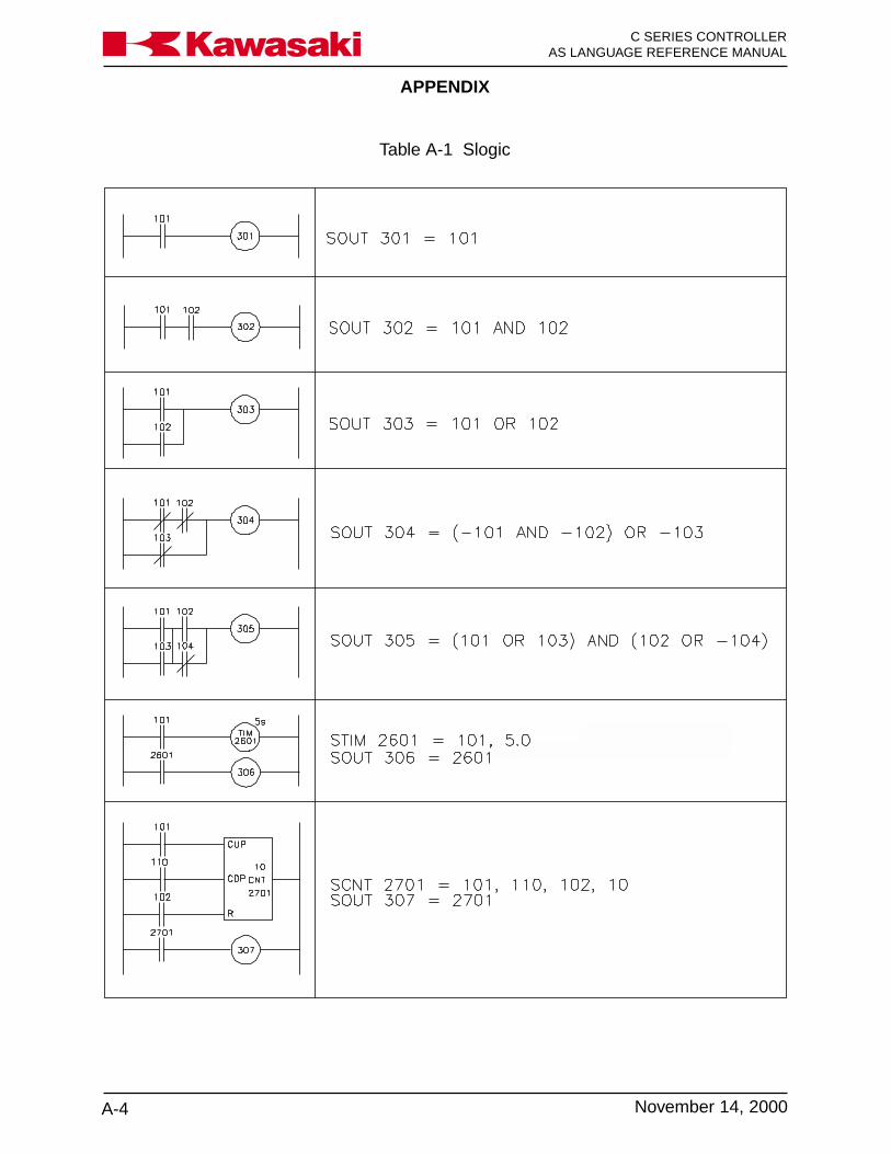
APPENDIX
C SERIES CONTROLLERAS LANGUAGE REFERENCE MANUAL
A-4 November 14, 2000
Ka a aw s k
Table A-1 Slogic
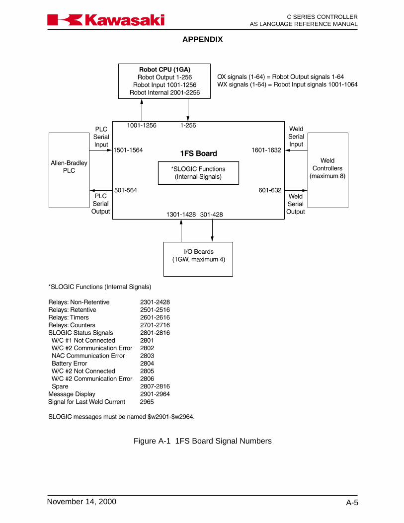
APPENDIX
A-5November 14, 2000
Ka a aw s k C SERIES CONTROLLERAS LANGUAGE REFERENCE MANUAL
Figure A-1 1FS Board Signal Numbers
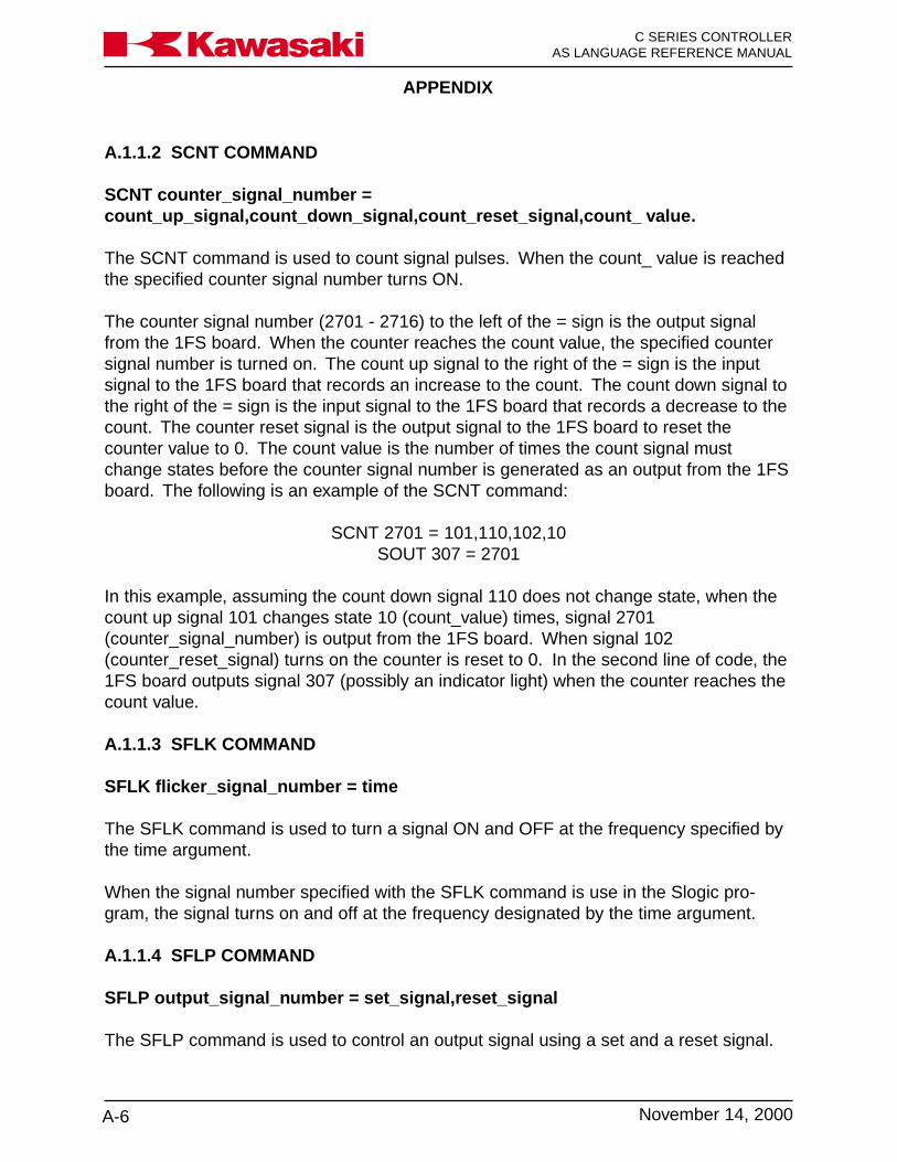
APPENDIX
C SERIES CONTROLLERAS LANGUAGE REFERENCE MANUAL
A-6 November 14, 2000
Ka a aw s k
A.1.1.2 SCNT COMMAND
SCNT counter_signal_number =count_up_signal,count_down_signal,count_reset_signal,count_ value.
The SCNT command is used to count signal pulses. When the count_ value is reachedthe specified counter signal number turns ON.
The counter signal number (2701 - 2716) to the left of the = sign is the output signalfrom the 1FS board. When the counter reaches the count value, the specified countersignal number is turned on. The count up signal to the right of the = sign is the inputsignal to the 1FS board that records an increase to the count. The count down signal tothe right of the = sign is the input signal to the 1FS board that records a decrease to thecount. The counter reset signal is the output signal to the 1FS board to reset thecounter value to 0. The count value is the number of times the count signal mustchange states before the counter signal number is generated as an output from the 1FSboard. The following is an example of the SCNT command:
SCNT 2701 = 101,110,102,10SOUT 307 = 2701
In this example, assuming the count down signal 110 does not change state, when thecount up signal 101 changes state 10 (count_value) times, signal 2701(counter_signal_number) is output from the 1FS board. When signal 102(counter_reset_signal) turns on the counter is reset to 0. In the second line of code, the1FS board outputs signal 307 (possibly an indicator light) when the counter reaches thecount value.
A.1.1.3 SFLK COMMAND
SFLK flicker_signal_number = time
The SFLK command is used to turn a signal ON and OFF at the frequency specified bythe time argument.
When the signal number specified with the SFLK command is use in the Slogic pro-gram, the signal turns on and off at the frequency designated by the time argument.
A.1.1.4 SFLP COMMAND
SFLP output_signal_number = set_signal,reset_signal
The SFLP command is used to control an output signal using a set and a reset signal.

APPENDIX
A-7November 14, 2000
Ka a aw s k C SERIES CONTROLLERAS LANGUAGE REFERENCE MANUAL
When the SLOGIC program is executing and the set signal specified with the SFLPcommand is on, the output signal number turns on. When the reset signal specified withthe SFLP command is on, the output signal number turns off. When the set signal andthe reset signal specified with the SFLP command are both on, the output signal num-ber is turned off.
A.1.1.5 STIM COMMAND
STIM timer_signal_number = input_signal,time
The STIM command is used to turn ON an output signal after an input signal is ON for aspecified time.
The timer signal number to the left of the = sign is turned on when the timer reaches thetime value on the right. The input signal on the right of the = sign is the input signal tothe 1FS board to start the timer. The time value is the length of time in seconds. Whenthe input signal turns on timing starts. When the specified time elapses, the timer signalnumber turns on. The following is an example of the STIM command:
STIM 2601 = 36,2.4SOUT 360 = 2601
In this example, 2.4 seconds after input signal 36 turns on, signal 2601 (timer signalnumber) turns on. In the second line of code, the 1FS board outputs signal 360 (possi-bly an indicator light) when the timer has reached the time value.
A.1.1.6 RI/O MONITOR, AUX 180
This function allows the user to view various functions regarding the remote I/O func-tions (Figure A-2).
1 SIG NAL S TATUS2 TIM ER AND CO UNTERSTATUS3 SLO G IC M O NITO R4 LAST W ELD DATA5 SLO G IC STATUS
FU NCTIO N N UM BER :F4
AUX .180 R I/O MO NITO R
F3F�F1
Figure A-2 RI/O Monitor

APPENDIX
C SERIES CONTROLLERAS LANGUAGE REFERENCE MANUAL
A-8 November 14, 2000
Ka a aw s k
Figure A-3 RI/O Signal Status Screens
The SIGNAL STATUS screens shown in figure A-3 allows the user to view the status ofall remote I/O and robot signals. Figure A-3 shows two of five signal status screens.Use the NEXT PG buttons to scroll to the remaining screens.
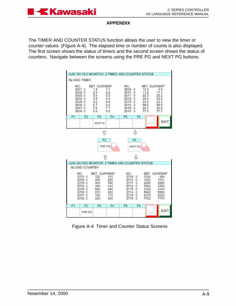
APPENDIX
A-9November 14, 2000
Ka a aw s k C SERIES CONTROLLERAS LANGUAGE REFERENCE MANUAL
The TIMER AND COUNTER STATUS function allows the user to view the timer orcounter values (Figure A-4). The elapsed time or number of counts is also displayed.The first screen shows the status of timers and the second screen shows the status ofcounters. Navigate between the screens using the PRE PG and NEXT PG buttons.
Figure A-4 Timer and Counter Status Screens
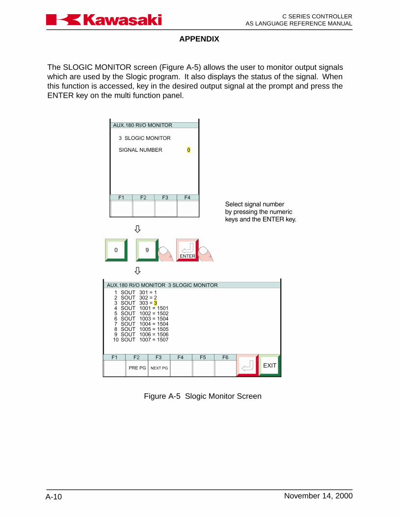
APPENDIX
C SERIES CONTROLLERAS LANGUAGE REFERENCE MANUAL
A-10 November 14, 2000
Ka a aw s k
The SLOGIC MONITOR screen (Figure A-5) allows the user to monitor output signalswhich are used by the Slogic program. It also displays the status of the signal. Whenthis function is accessed, key in the desired output signal at the prompt and press theENTER key on the multi function panel.
Figure A-5 Slogic Monitor Screen

APPENDIX
A-11November 14, 2000
Ka a aw s k C SERIES CONTROLLERAS LANGUAGE REFERENCE MANUAL
The LAST WELD DATA screen displays the weld sequence parameters. Use the NEXTPG and PRE PG buttons to scroll between the three available screens. Figure A-6shows LAST WELD DATA screens.
Figure A-6 Last Weld Data Screens
AUX.180 R I/O M ONITO R 4 LAST W ELD DATA
F6
EX ITF5F4F3
N E XT PG
F�F1
� �F�
PRE PG F3
N E XT PG
� �AUX.180 R I/O M ONITO R 4 LAST W ELD DATA
F6
EX ITF5F4F3
N E XT PG
F1 F�
PRE PG
� �F�
PRE PG
F3
N E XT PG
� �AUX.180 R I/O M ONITO R 4 LAST W ELD DATA
F6
EX ITF5F4F1 F�
PRE PG
F3
W E LD C O N T. #1 W E LD C O N T. #2 W ELD C O N T. #3
SE QUE NC E N O. 12 12 12STEP PER NO . 9 9 9PRE SENT STEP COM P. COM P. COM P.W E LDS M A DE 3456 3456 3456PO W E R FAC TO R 6 deg 6 deg 6 degW E LD PRIM A RY CURR E NT 6666 A 6666 A 6666 AW E LD SE C. CURRE NT # 1 45.6 KA 45.6 KA 45.6 KAW E LD SE C. CURRE NT # 2 45.6 KA 45.6 KA 45.6 KAW E LD LINE V OLTAG E 456 V 456 V 456 V
W ELD C O NT. #4 W E LD C O N T. #5 W E LD C O N T. #6
SE QUE NC E N O. 12 12 12STEP PER NO . 9 9 9PRE SENT STEP COM P. COM P. COM P.W E LDS M A DE 3456 3456 3456PO W E R FAC TO R 6 deg 6 deg 6 degW E LD PRIM A RY CURR E NT 6666 A 6666 A 6666 AW E LD SE C. CURRE NT # 1 45.6 KA 45.6 KA 45.6 KAW E LD SE C. CURRE NT # 2 45.6 KA 45.6 KA 45.6 KAW E LD LINE V OLTAG E 456 V 456 V 456 V
W ELD C O NT. #7 W E LD C ON T. #8
SE QUE NC E N O. 12 12STEP PER NO . 9 9PRE SENT STEP COM P. COM P.W E LDS M A DE 3456 3456PO W E R FAC TO R 6 deg 6 degW E LD PRIM A RY CURR E NT 6666 A 6666 AW E LD SE C. C UR R E N T # 1 45.6 KA 45.6 KAW E LD SE C. C UR R E N T # 2 45.6 KA 45.6 KAW E LD LINE V OLTAG E 456 V 456 V
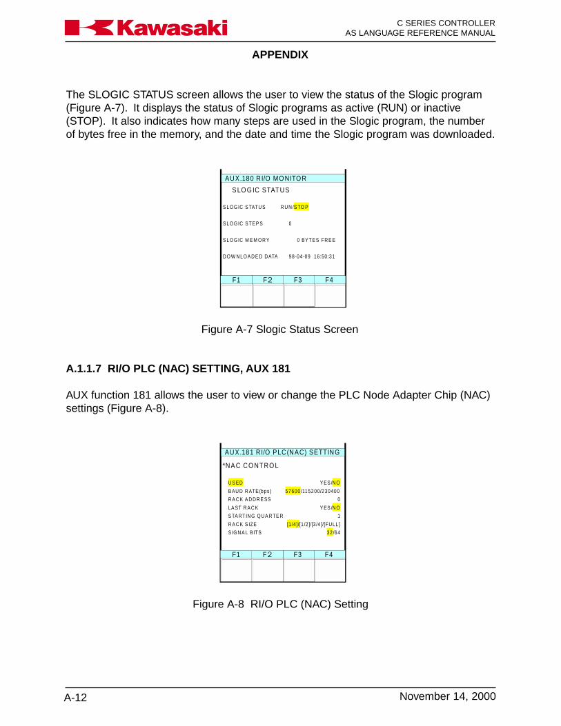
APPENDIX
C SERIES CONTROLLERAS LANGUAGE REFERENCE MANUAL
A-12 November 14, 2000
Ka a aw s k
The SLOGIC STATUS screen allows the user to view the status of the Slogic program(Figure A-7). It displays the status of Slogic programs as active (RUN) or inactive(STOP). It also indicates how many steps are used in the Slogic program, the numberof bytes free in the memory, and the date and time the Slogic program was downloaded.
F4
AUX.180 R I/O MO NITO R
F3F�F1
S LO G IC STATUS
S LO G IC S TATU S R U N /S TO P
S LO G IC S TE P S 0
S LO G IC M E M O R Y 0 BY TE S FR E E
D O W N LO A D E D D ATA 98-04-09 16 :50 :31
Figure A-7 Slogic Status Screen
A.1.1.7 RI/O PLC (NAC) SETTING, AUX 181
AUX function 181 allows the user to view or change the PLC Node Adapter Chip (NAC)settings (Figure A-8).
F4
AUX.181 RI/O PLC(NAC) SETTING
F3F�F1
*NA C CO NTRO L
U S ED Y ES /N O
B AU D R ATE (bps ) 57600 /115200/230400
R A C K A D D RE SS 0
LA ST R A C K Y ES /N O
S TA RT IN G QU A R TE R 1
R A C K S IZE [1 /4 ]/[1 /2 ]/[3 /4 ]/[FULL ]
S IG N A L BITS 32 /64
Figure A-8 RI/O PLC (NAC) Setting
APPENDIX
A-13November 14, 2000
Ka a aw s k C SERIES CONTROLLERAS LANGUAGE REFERENCE MANUAL
A.1.2 CONTROLNET
The ControlNet network (Figure A-9) is an open control network that provides real-time,high-throughput applications by linking PLC processors, I/O, computers, operator inter-faces, and other intelligent devices. The ControlNet network combines the functionalityof an I/O network and a peer-to-peer network, while providing high-speed performancefor both functions.
The ControlNet network transfers data at 5M bit/s, and provides repeatable transfers ofcritical control data (e.g., I/O updates and processor interlocking).
Due to its fast update times, the network can support highly distributed systems, espe-cially those with high-speed digital I/O or heavy analog I/O content. I/O chassis andother devices can be located hundreds of meters from PLC processors; or, for distrib-uted processing, a processor can be located at the I/O chassis where it can monitor itsown resident I/O while communicating via the network to a supervisory controller.
The ControlNet network can process the following automation and control data on asingle coaxial cable: peer-to-peer messaging, remote programming, troubleshooting,and I/O updates and PLC processor interlocking.
I/O and PLC processor interlocking update times that match application requirementscan be selected. The network’s media access method places a higher priority on I/Oupdates and processor interlocking; these messages always take precedence overtransfers of non-time-critical data (e.g., program uploads/ downloads and messaging).The network simplifies PLC programming by eliminating the need to program blocktransfers.

APPENDIX
C SERIES CONTROLLERAS LANGUAGE REFERENCE MANUAL
A-14 November 14, 2000
Ka a aw s k
ON OFF
TEACH LOCK
AC115V 1A
HOST
MFP
HOLD RUN TEACH REPEAT
CYCLE STARTERROR RESET
MOTOR POWERERROR
EMERGENCY STOP
ControlNet Network
DeviceNet Network
PLC-5/20Cprocessor
Windows NT/95computer runningRSView software
with RSLinx
1770-KFCserial/parallel
interface module
C Series Controllerwith 1FS board
PanelView 1200eOperator Terminal
Windows NT/95computer running
RSI PLC-5 A.I.programming software
with RSLinx
1784-KTCX
PLC-5/40Cprocessor
PLC-5/40Cprocessor
FLEX I/O adapter1794-ACN
DeviceNetscanner
1771-SDN
ControlNet I/O adapter1771-ACNR
Windows NT/95computer with1786-CP cable
1784-KTC
Figure A-9 ControlNet Network
A ControlNet network is simple and cost-effective to install, and offers flexible installationoptions. Allen-Bradley offers PLC processors with built-in ControlNet communication,ControlNet adapters for I/O chassis, and ControlNet interface cards for personal com-puters. Although the ControlNet network is based on bus technology, repeaters can beused to implement tree and star topologies. For added reliability, a redundant set ofcables may be added between nodes. The additional cables provide a backup path if aprimary cable fails. Each node compares the quality of the signals from each cable anduses the cable with the better signal. The 1FS board provides a redundant connectionto the network via two BNC connectors (channel A and B).
Windows NT/95 computers can access real-time data over the network using RSLinxsoftware. This software functions as a communications engine for software productssuch as Rockwell Software’s man machine interface software RSView, and program-ming software such as PLC-5 A.I. series programming software. RSLinx can also pro-vide plant floor data to commercially available applications (e.g., Microsoft Excel andAccess) for display, logging, or trending.
APPENDIX
A-15November 14, 2000
Ka a aw s k C SERIES CONTROLLERAS LANGUAGE REFERENCE MANUAL
The ControlNet network provides real-time communication between PLC processors,I/O chassis, personal computers, third-party hardware and software, and related I/Odevices. The network also allows the user to perform other functions such as program-ming the processors on the network and configuring network devices from a singleterminal.
The network uses standard RG-6 coaxial cable and BNC connectors. ControlNet alsosupports fiber-optic media. Fiber-optic repeaters allow increased network distances andaccommodate changes in topology.
The network uses taps with integrated drop cables for node connections. Up to 99addressable nodes (with taps) can be installed anywhere along the network’s trunkcable, with a maximum length per segment ranging from 250 meters (820 ft) to 1,000meters (3,280 ft), depending on how many taps are used. There is no minimum tapseparation. The network can be accessed from every node, including ControlNet I/Oadapters, using the network access port.
The ControlNet network is compatible with a range of products, and can be added toexisting systems. The PLC-5 processor includes standard ports for communication withdevices on Universal Remote I/O and Data Highway Plus networks.
The ControlNet network provides a time-critical link between PLC processors and I/Odevices, and the architectural link between information and device layers of a communi-cation architecture.
APPENDIX
C SERIES CONTROLLERAS LANGUAGE REFERENCE MANUAL
A-16 November 14, 2000
Ka a aw s k
A.2 MOTION CONTROL AND LOCATION DEFINITION
A.2.1 C1MOVE AND C2MOVE COMMANDS
C1MOVE location, clamp numberC2MOVE location, clamp number.
C1MOVE and C2MOVE commands are used to create a circularinterpolation path.
The commands C1MOVE and C2MOVE specify the arc of the robotpath to reach the taught location. Three locations are needed forthe controller to calculate a circular path trajectory.
The first location is the beginning of the arc and can be specifiedwith any of the following commands: Align, C1MOVE, C2MOVE,DELAY, DRAW, TDRAW, DRIVE, HOME, JMOVE, JAPPRO,JDEPART, LMOVE, LAPPRO, LDEPART, STABLE, or XMOVE.
The second location is defined by the C1MOVE command and is alocation that is on the arc that connects the arc beginning and arcending points.
The C2MOVE command defines the arc end point.
location: Specifies the destination of the C1MOVE or C2MOVE.
The location specified must be the name of a location variable andcan be a precision point, transformation, or compound transforma-tion location.
clamp number: Specifies the clamp number to open or close when the robotreaches the destination location.
A positive number opens the clamp.
A negitive number closes the clamp.
If the clamp number is omitted, the clamp signal does not change.

APPENDIX
A-17November 14, 2000
Ka a aw s k C SERIES CONTROLLERAS LANGUAGE REFERENCE MANUAL
JMOVE pt1C1MOVE pt2C2MOVE pt3
pt1
pt2
pt3
pt1
pt2
pt3
pt4
pt1
pt2
pt3
pt4
pt5
JMOVE pt1C1MOVE pt2C2MOVE pt3C1MOVE pt4C2MOVE pt5
JMOVE pt1C1MOVE pt2C2MOVE pt3C1MOVE pt4C2MOVE pt1
Figure A-10 Circular Interpolation
Example:
APPENDIX
C SERIES CONTROLLERAS LANGUAGE REFERENCE MANUAL
A-18 November 14, 2000
Ka a aw s k
A.2.2 FMOVE COMMAND
FMOVE location, clamp number
The FMOVE command is used in conjunction with the FIXED TOOLDIMENSIONS function and allows the user to program movesrelative to an external fixed point in the work envelope.
This type of interpolation is called fixed linear interpolation (FLIN).
For a FMOVE, the robot path is calculated to maintain a set rela-tionship to a fixed point.
Applications for FLIN moves include moving a part around a fixedsealing dispenser or a fixed stud welding gun.
Figure A-11 shows the auxiliary function screen used to enter thedimensions for a fixed tool used with FLIN moves.
Figure A-12 shows how the path of a windshield moved by a robotis different with a LMOVE and FMOVE.
The FMOVE path enables the programmer to reduce the number ofprogrammed points needed to maintain a fixed distance from thesealing dispenser.
location: Specifies the destination of the FMOVE.
The location specified must be the name of a location variable andcan be a precision point, transformation, or compound transforma-tion location.
clamp number: Specifies the clamp number to open or close when the robotreaches the destination location.
A positive number opens the clamp.
A negitive number closes the clamp.
If the clamp number is omitted, the clamp signal does not change.
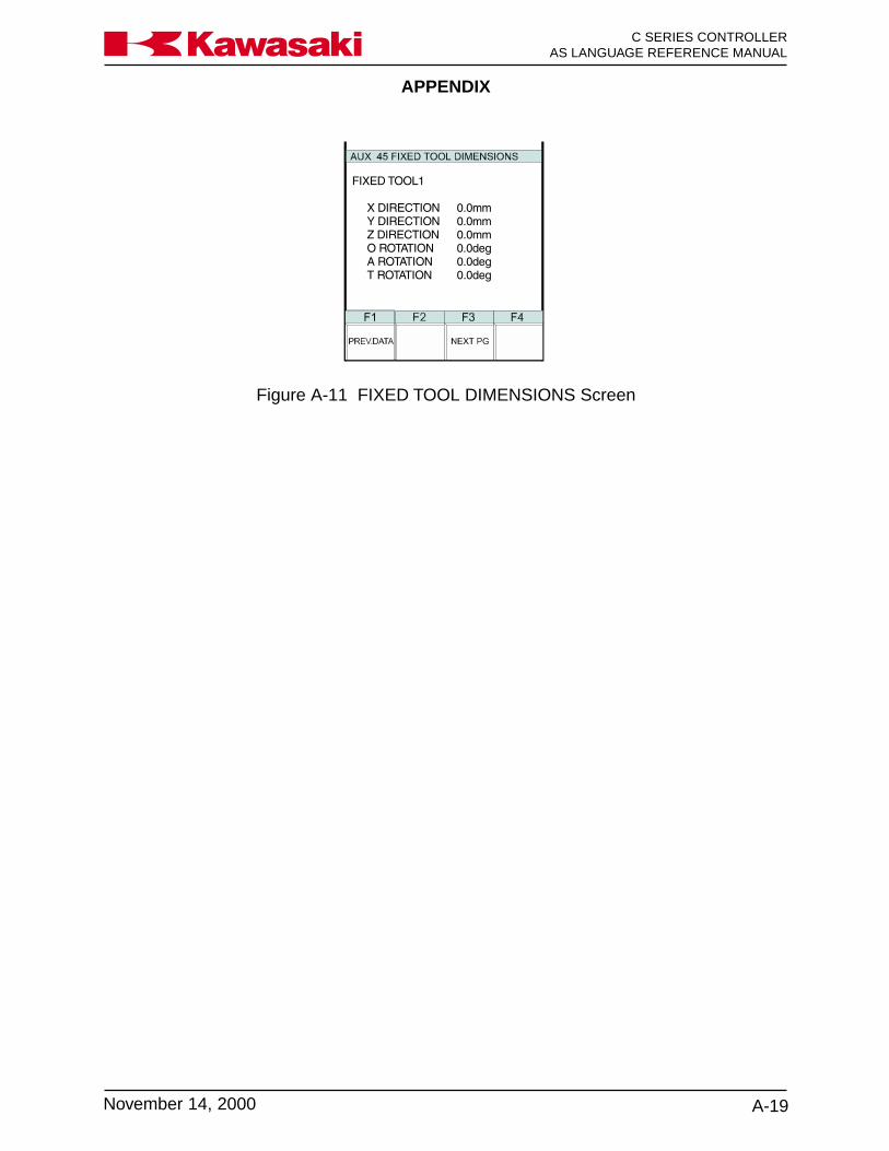
APPENDIX
A-19November 14, 2000
Ka a aw s k C SERIES CONTROLLERAS LANGUAGE REFERENCE MANUAL
Figure A-11 FIXED TOOL DIMENSIONS Screen

APPENDIX
C SERIES CONTROLLERAS LANGUAGE REFERENCE MANUAL
A-20 November 14, 2000
Ka a aw s k
Figure A-12 FMOVE Command

APPENDIX
A-21November 14, 2000
Ka a aw s k C SERIES CONTROLLERAS LANGUAGE REFERENCE MANUAL
A.2.3 MVWAIT COMMAND
MVWAIT distance in mm or time in seconds
The MVWAIT command is used to determine when the next program instruction isexecuted. Figure A-10 shows two examples of the MVWAIT command with thePREFETCH.SIGINS switch in the on position.
Figure A-13 MVWAIT Command
Location pt1
LMOVE pt1MVWAIT 100mmSIGNAL 21
100 mm
Signal 21 Turns ON Here
Robot Path To pt1
Location pt1
LMOVE pt1MVWAIT .5SSIGNAL 21
Position Of Robot .5 Seconds After Beginning Travel To Location pt1
Robot Path To pt1
APPENDIX
C SERIES CONTROLLERAS LANGUAGE REFERENCE MANUAL
A-22 November 14, 2000
Ka a aw s k
A.2.4 BSPEED COMMAND
BSPEED speed
The BSPEED command is used to change the playback speed of block step programs.The actual playback speed of the program is the product of the specified speed in theBSPEED command combined with the repeat condition speed and the program stepspeed. The playback speed cannot exceed 100%. The robot continues to operate atthe specified BSPEED until the next BSPEED command is processed.
A.2.5 TRHERE COMMAND
TRHERE location variable
The TRHERE command is used to add the traverse axis component to the compoundtransformation. The specified location variable can be either a transformation location ora compound transformation.

APPENDIX
A-23November 14, 2000
Ka a aw s k C SERIES CONTROLLERAS LANGUAGE REFERENCE MANUAL
A.3 SYSTEM PARAMETERS AND SWITCHES
A.3.1 NCHON AND NCHOFF COMMANDS
The NTCHON and NCHOFF commands are monitor or program instruction commandsthat turn the notch filter on and off. The notch filter affects the processing parameters ofthe PWM for servo motor speed control. The new setting of the notch filter, as specifiedwith the NTCHON or NTCHOFF command is effective after the execution of the follow-ing commands: PRIME, STEP, MSTEP, and EXECUTE. Before utilizing the NTCHONand NTCHOFF commands it is recommended the Kawasaki Robotics engineering groupis contacted to provide details regarding program playback performance.
A.3.2 WEIGHT COMMAND
WEIGHT payload
The WEIGHT command that affects the processing parameters of the PWM for servomotor speed, acceleration, and deceleration control is a program instruction. The pay-load is specified in kg up to the maximum payload.
A.3.3 MC COMMAND
The MC command is used as a prefix to monitor commands to allow monitor commandsto be processed within a program. The MC commands are: MCABORT, MCCONTINUE,MCERESET, MCEXECUTE, MCHOLD, and MCSPEED.
A.3.4 AUTOSTART.PC SWITCHES
The AUTOSTART.PC system switches allow execution of the specified process controlprogram to begin as soon as controller power is applied. Three process control pro-grams can begin execution with this process, AUTOSTART.PC, AUTOSTART2.PC, andAUTOSTART3.PC. When the process control programs to be used with theAUTOSTART.PC switches are created they must be named to correspond with thespecified switch. For example, the process control program named AUTOSTART2.PCbegins execution when control power is applied if AUTOSTART2.PC system switch isturned on.
A.3.5 ERRSTART.PC SWITCH
The ERRSTART.PC system switch allows execution of the specified process controlprogram to begin as soon as a specified error occurs. When the process control pro-gram to use with the ERRSTART.PC switch is created, it is named ERRSTART.PC tocorrespond with the specified switch.

APPENDIX
C SERIES CONTROLLERAS LANGUAGE REFERENCE MANUAL
A-24 November 14, 2000
Ka a aw s k
A.3.6 AFTER.WAIT.TMR SWITCH
The AFTER.WAIT.TMR system switch determines when timers specified in block stepprograms begin timing. With the AFTER.WAIT.TMR switch in the off state, timing beginswhen the robot reaches coincidence with the taught location. With theAFTER.WAIT.TMR switch in the ON position, timing begins when the robot reachescoincidence with the taught location and all wait conditions are satisfied.
A.4 FUNCTION COMMANDS
A.4.1 DEXT FUNCTION
real variable = DEXT (location name, element number)
The DEXT command is a real value function used to assign an element of a locationvariable to a real variable. The following example of the DEXT function assigns the y(element 2) distance component of the transformation location loc1 to the real valueloc.y.
loc.y = DEXT (loc1, 2)
In the above example, if the components of location loc1 are 1151, 1375, 950, -36, 87,113, the value of real variable loc.y is 1375.
A.4.2 PRIORITY FUNCTION
real variable =PRIORITY
The PRIORITY function is a real value function used to assign the priority level of thecurrent program to a real variable. The following example of the PRIORITY functionassigns the value of the program (as specified with the LOCK command) to the realvariable stat.
stat = PRIORITY
In the above example, if the currently selected program is defined with the LOCK 2command, the value of stat is 2.
A.4.3 PCSCAN COMMAND
PCSCAN time.
The PCSCAN command is a process control program instruction used to set the scantime of the process control program. If the specified time is 1.5 seconds, the executionof the program is processed every 1.5 seconds. If the specified time is less then thenormal processing time of the program, this command does not affect the program.
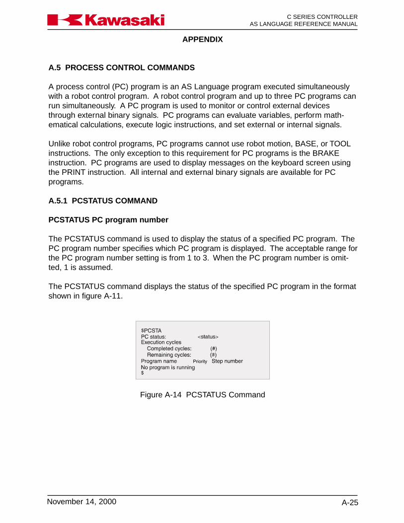
APPENDIX
A-25November 14, 2000
Ka a aw s k C SERIES CONTROLLERAS LANGUAGE REFERENCE MANUAL
A.5 PROCESS CONTROL COMMANDS
A process control (PC) program is an AS Language program executed simultaneouslywith a robot control program. A robot control program and up to three PC programs canrun simultaneously. A PC program is used to monitor or control external devicesthrough external binary signals. PC programs can evaluate variables, perform math-ematical calculations, execute logic instructions, and set external or internal signals.
Unlike robot control programs, PC programs cannot use robot motion, BASE, or TOOLinstructions. The only exception to this requirement for PC programs is the BRAKEinstruction. PC programs are used to display messages on the keyboard screen usingthe PRINT instruction. All internal and external binary signals are available for PCprograms.
A.5.1 PCSTATUS COMMAND
PCSTATUS PC program number
The PCSTATUS command is used to display the status of a specified PC program. ThePC program number specifies which PC program is displayed. The acceptable range forthe PC program number setting is from 1 to 3. When the PC program number is omit-ted, 1 is assumed.
The PCSTATUS command displays the status of the specified PC program in the formatshown in figure A-11.
Figure A-14 PCSTATUS Command

APPENDIX
C SERIES CONTROLLERAS LANGUAGE REFERENCE MANUAL
A-26 November 14, 2000
Ka a aw s k
A.5.2 PC PROGRAM CONTROL
PCEXECUTE program_name,execution_cycles,start_step
Executes a PC program
program_name: Name of the program to execute as a PC program. If omitted, theprogram last executed with the PCEXECUTE command is selected.
execution_cycles: A number specifying how many times the program executes. Ifomitted, it is set to 1. Entering a negative number causes the pro-gram to execute continuously.
starting_step: Step number of the program to start execution.
PCABORT Aborts execution of the PC program. This is similar to the ABORTmonitor command used for robot control programs, except it abortsthe current PC program. Program execution is resumed with thePCCONTINUE command.
PCEND task_number
Terminates the execution of the PC program when the current PCprogram executes a STOP instruction.
task_number: Entered as 1 or -1, if omitted, 1 is assumed.
When the current PC program executes a STOP instruction (or anequivalent instruction such as RETURN in the robot control pro-gram), execution of the PC program is stopped immediately, regard-less of remaining cycles. If the current cycle is not completed,execution is resumed with the PCCONTINUE command.
This command waits until the program stops at the STOP instruc-tion. If the PC program loops internally and the current executioncycle never ends, the PCEND command waits indefinitely. To can-cel the PCEND command, enter a negative number. To terminate aPC program that loops endlessly, use the PCABORT command.
APPENDIX
A-27November 14, 2000
Ka a aw s k C SERIES CONTROLLERAS LANGUAGE REFERENCE MANUAL
PCCONTINUE next
Resumes execution of an interrupted PC program. The NEXTargument is used to skip WAIT instructions.
When the PC program is interrupted by a PAUSE, PCABORT in-struction, or an error, the PCCONTINUE command begins execu-tion of the PC program at the step following the interrupted step.
PCKILL Initializes the PC program stack.
The PCKILL command clears the PC program stack, but does notdelete the PC program(s). If a PC program is interrupted for anyreason, the program is not removed from the stack.
The current PC program must be removed from the stack with thePCKILL command before it can be deleted.
PCSTEP program_name,execution_cycles,start_step.
The PCSTEP command is used to execute a single step of a PCprogram.
program_name: Name of the PC program for step execution.
execution_cycles: Specifies the number of cycles for the PC program to execute withthe PCSTEP command.
start_step: The step number of the program to execute first.
PCSCAN time
The PCSCAN command is used to specify the length of time ittakes to process the PC program one time. The time is specified inincrements of one second. If the PCSCAN command is not used,the PC program is processed at the CPU speed.
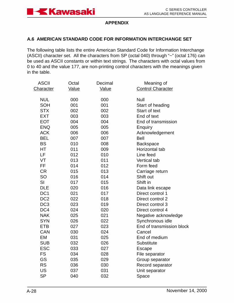
APPENDIX
C SERIES CONTROLLERAS LANGUAGE REFERENCE MANUAL
A-28 November 14, 2000
Ka a aw s k
A.6 AMERICAN STANDARD CODE FOR INFORMATION INTERCHANGE SET
The following table lists the entire American Standard Code for Information Interchange(ASCII) character set. All the characters from SP (octal 040) through “~” (octal 176) canbe used as ASCII constants or within text strings. The characters with octal values from0 to 40 and the value 177, are non-printing control characters with the meanings givenin the table.
ASCII Octal Decimal Meaning ofCharacter Value Value Control Character
NUL 000 000 NullSOH 001 001 Start of headingSTX 002 002 Start of textEXT 003 003 End of textEOT 004 004 End of transmissionENQ 005 005 EnquiryACK 006 006 AcknowledgementBEL 007 007 BellBS 010 008 BackspaceHT 011 009 Horizontal tabLF 012 010 Line feedVT 013 011 Vertical tabFF 014 012 Form feedCR 015 013 Carriage returnSO 016 014 Shift outSI 017 015 Shift inDLE 020 016 Data link escapeDC1 021 017 Direct control 1DC2 022 018 Direct control 2DC3 023 019 Direct control 3DC4 024 020 Direct control 4NAK 025 021 Negative acknowledgeSYN 026 022 Synchronous idleETB 027 023 End of transmission blockCAN 030 024 CancelEM 031 025 End of mediumSUB 032 026 SubstituteESC 033 027 EscapeFS 034 028 File separatorGS 035 029 Group separatorRS 036 030 Record separatorUS 037 031 Unit separatorSP 040 032 Space

APPENDIX
A-29November 14, 2000
Ka a aw s k C SERIES CONTROLLERAS LANGUAGE REFERENCE MANUAL
ASCII Octal Decimal ACII Octal DecimalCharacter Value Value Character Value Value
! 041 033 P 120 080“ 042 034 Q 121 081# 043 035 R 122 082$ 044 036 S 123 083% 045 037 T 124 084& 046 038 U 125 085‘ 047 039 V 126 086( 050 040 W 127 087) 051 041 X 130 088* 052 042 Y 131 089+ 053 043 Z 132 090‘ 054 044 [ 133 091- 055 045 \ 134 092ù 056 046 ] 135 093/ 057 047 ^ 136 0940 060 048 - 137 0951 061 049 ‘ 140 0962 062 050 a 141 0973 063 051 b 142 0984 064 052 c 143 0995 065 053 d 144 1006 066 054 e 145 1017 067 055 f 146 1028 070 056 g 147 1039 071 057 h 150 104: 072 058 i 151 105; 073 059 j 152 106< 074 060 k 153 107= 075 061 l 154 108> 076 062 m 155 109? 077 063 n 156 110@ 100 064 o 157 111

APPENDIX
C SERIES CONTROLLERAS LANGUAGE REFERENCE MANUAL
A-30 November 14, 2000
Ka a aw s k
ASCII Octal Decimal ACII Octal DecimalCharacter Value Value Character Value Value
A 101 065 p 160 12B 102 066 q 161 113C 103 067 r 162 114D 104 068 s 163 115E 105 069 t 164 116F 106 070 u 165 117G 107 071 v 166 118H 110 072 w 167 119I 111 073 x 170 120J 112 074 y 171 121K 113 075 z 172 122L 114 076 { 173 123M 115 077 l 174 124N 116 078 } 175 125O 117 079 ~ 176 126
DEL 177 127 Delete

APPENDIX
A-31November 14, 2000
Ka a aw s k C SERIES CONTROLLERAS LANGUAGE REFERENCE MANUAL
A.7 KEYWORDS LIST
*LegandM (Monitor command) E (Editor command) P (Program instruction) S (Switch)F (Function) O (Operator) K (Other keywords)
ABBRV. NAME FUNCTION TYPE* FORMAT (ARGUMENT)
AB ABORT Stop program execution M ABORTAB ABOVE Change configuration P ABOVEABS ABS Absolute value F ABS (Real_value_expression)ACCE ACCEL Change acceleration factor P ACCEL acceleration ALWAYSACCU ACCURACY Change accuracy P ACCURACY range ALWAYSAF AFTER.WAIT. Controls when timer S ...AFTER.WAIT.TMR...
TIMER function beginsAL ALIGN Align tool Z axis P ALIGNA ALWAYS Effective afterwards K ...ALWAYSAND AND Logical AND O ...AND...ARC ARC Dedicated signal to welding S ARC ON/OFF
power supplyARMIOSET ARMIOSET Arm ID board I/O signals set M ARMIOSET robot No.,OX sig._No.
_num._of_ OX_sig.,WX_sig._No._num._of_ WX_sig.
ASC ASC Get ASCII value F ASC (string, index)ATAN2 ATAN2 Arctangent F ATAN2 (real-value, real-value)AUTOSTART. AUTOSTART.PC Starts PC program execution S ...AUTOSTART.PC...AUTOSTART2. AUTOSTART2.PC Starts PC program execution S ...AUTOSTART2.PC...AUTOSTART3. AUTOSTART3.PC Starts PC program execution S ...AUTOSTART3.PC...AVE_TRANS AVE_TRANS Returns the average of two F AVE_TRANS(transformation_
transformation locations value, transformation_value2BAND BAND Binary logical AND O ....BAND....BA BASE Change base coordinate system M/P BASE transformation_valueBASE BASE Returns the origin of the base F BASE
coordinate systemBAT BATCHK Battery error check on power up M BATCHKBE BELOW Change configuration P BELOWBI BITS Set output signals M/P BITS irst_signal,number_of_
signals =valueBITS BITS Get signal states F BITS (first_signal,number_of_
signals)BOR BOR Binary logical OR O ...BOR...BRA BRAKE Brake robot motion P BRAKEBRE BREAK Cause break in CP motion P BREAKBSP BSPEED Sets speed of block programs P BSPEED_speedBX BXOR Binary exclusive logical OR O ...BXOR...BY BY K BY...C CHANGE Change program E C program name, step_numberCAL CALL Call subroutine P CALL program_nameCAS CASE CASE structure P CASE number OF...VALUE... ENDCH CHECK.HOLD Changes useage of some S CHECK.HOLD
motion commands
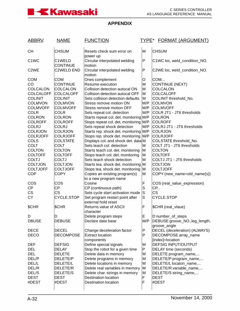
APPENDIX
C SERIES CONTROLLERAS LANGUAGE REFERENCE MANUAL
A-32 November 14, 2000
Ka a aw s k
ABBRV. NAME FUNCTION TYPE* FORMAT (ARGUMENT)
CH CHSUM Resets check sum error on M CHSUMpower up
C1WC C1WELD Circular interpolated welding P C1WC loc, weld_condition_NO.CONTINUE motion
C2WE C2WELD END Circular interpolated welding P C2WE loc, weld_condition_NO.motion
COM COM Ones complement O COM...CO CONTINUE Resume execution M CONTINUE (NEXT)COLCALON COLCALON Collision detection autocal ON M COLCALONCOLCALOFF COLCALOFF Collision detection autocal OFF M COLCALOFFCOLINIT COLINIT Sets collision detection defaults M COLINIT threshold_No.COLMVON COLMVON Stress remove motion ON M/P COLMVONCOLMVOFF COLMVOFF Stress remove motion OFF M/P COLMVOFFCOLR COLR Sets repeat col. detection M/P COLR JT1 - JT6 thresholdsCOLRON COLRON Starts repeat col. det. monitoring M/P COLRONCOLROFF COLROFF Stops repeat col. det. monitoring M/P COLROFFCOLRJ COLRJ Sets repeat shock detection M/P COLRJ JT1 - JT6 thresholdsCOLRJON COLRJON Starts rep. shock det. monitoring M/P COLRJONCOLRJOFF COLRJOFF Stops rep. shock det. monitoring M/P COLRJOFFCOLS COLSTATE Displays col. and shock det. data M COLSTATE threshold_No.COLT COLT Sets teach col. detection M COLT JT1 - JT6 thresholdsCOLTON COLTON Starts teach col. det. monitoring M COLTONCOLTOFF COLTOFF Stops teach col. det. monitoring M COLTOFFCOLTJ COLTJ Sets teach shock detection M COLTJ JT1 - JT6 thresholdsCOLTJON COLTJON Starts tea. shock det. monitoring M COLTJONCOLTJOFF COLTJOFF Stops tea. shock det. monitoring M COLTJOFFCOP COPY Copies an existing program(s) M COPY (new_name=old_name(s))
to a new program nameCOS COS Cosine F COS (real_value_expression)CP CP CP (continuous path) S CP...CS CS Sets cycle start activation mode S CSCY CYCLE.STOP Set program restart point after S CYCLE.STOP
external hold reset$CHR $CHR Returns value of ASCII F $CHR (real_vlaue)
characterD D Delete program steps E D number_of_stepsDBUSE DEBUSE Declare data base M/P DEBUSE groove_NO.,leg_length,
groove_angleDECE DECEL Change deceleration factor P DECEL (deceleration) (ALWAYS)DECO DECOMPOSE Extract location P DECOMPOSE array_name
components [index]=locationDEF DEFSIG Define special signals M DEFSIG INPUT/OUTPUTDEL DELAY Stop the robot for a given time P DELAY time (seconds)DEL DELETE Delete data in memory M DELETE program_name,...DEL/P DELETE/P Delete programs in memory M DELETE/P program_name,...DEL/L DELETE/L Delete locations in memory M DELETE/L locaton_name,...DEL/R DELETE/R Delete real variables in memory M DELETE/R variable_name,...DEL/S DELETE/S Delete char. strings in memory M DELETE/S string_name,...DEST DEST Destination location F DEST#DEST #DEST Destination location F #DEST

APPENDIX
A-33November 14, 2000
Ka a aw s k C SERIES CONTROLLERAS LANGUAGE REFERENCE MANUAL
ABBRV. NAME FUNCTION TYPE* FORMAT (ARGUMENT)
DEXT DEXT Returns an element of a F DEXT (location name,index)location name
DIR DIRECTORY List data in memory M DIRECTORYDIR/P DIRECTORY/P List programs in memory M DIRECTORY/P (program_name,)DIR/L DIRECTORY/L List locations in memory M DIRECTORY/L (location_name,)DIR/R DIRECTORY/R List real variables in memory M DIRECTORY/R (variable_name,)DIR/S DIRECTORY/S List strings in memory M DIRECTORY/S (string_name,)DIS DISPIO_01 Changes I/O display from x/o to S DISPIO_01
1/0DIST DISTANCE Distance F DISTANCE (location, location)DL DLYSIG Output delay signal M/P DLYSIG (signal,time)DO DO Execute a program instruction M DO (instruction)DO DO DO structure P DO...UNTIL...DRA DRAW Move the robot by P DRAW (x, y, z)
given amount (mm)DRI DRIVE Move a single joint (degrees) P DRIVE (joint, degree, speed)DW DWRIST Change wrist configuration P DWRISTDX DX X component F DX (location)DY DY Y component F DY (location)DZ DZ Z component F DZ (location)E EXIT Exit editor mode E EED EDIT Enter editor mode M EDIT (program_name, step)EL ELSE IF structure P IF...ELSE...ENDENCCHK_E ENCCHK_EMG Checks position at E-stop S ENCCHK_EMGENCCHK_P ENCCHK_PON Checks current position with S ENCCHK_PON
position at power offEND END End control flow structure P FOR...END, CASE...ENDENV ENV_DATA Sets MFP environment data M ENV_DATAENV2 ENV2_DATA Sets MFP environment2 data M ENV2_DATAERE ERESET Reset error condition M ERESETERR ERRLOG Display history of errors M ERRLOGERROR ERROR Returns error number F ERRORERRS ERRSTART.PC Starts PC program at S ...ERRSTART.PC...
occurrence of specified errorEX EXECUTE Execute program M EXECUTE (program_name,
cycles,step_number)EX EXTCALL Call program selected by signals P EXTCALLF FIND Search characters E F character_stringFALSE FALSE False value F FALSE...FDEL FDELETE Delete PC card or disk files M FDELETE file_nameFDIR FDIRECTORY List PC card or disk files M FDIRECTORYFO FORMAT Formats PC card or floppy disk M FORMATFOR FOR Part of FOR/TO control flow P FOR (loop_variable=start_value)
structure TO (end_value)...ENDFR FRAME Transformation of relative F FRAME (location1, location2,
coordinate system location3,location4)FR FREE Show free memory amount M FREEG GOTO Branch execution P GOTO label IF conditionGET1WCON GET1_ Sets weld conditions DEBUSE M/P GET1WCON weld_condition_
WCON and SETPASS NO.,sp,a,v,wa,wf,pn
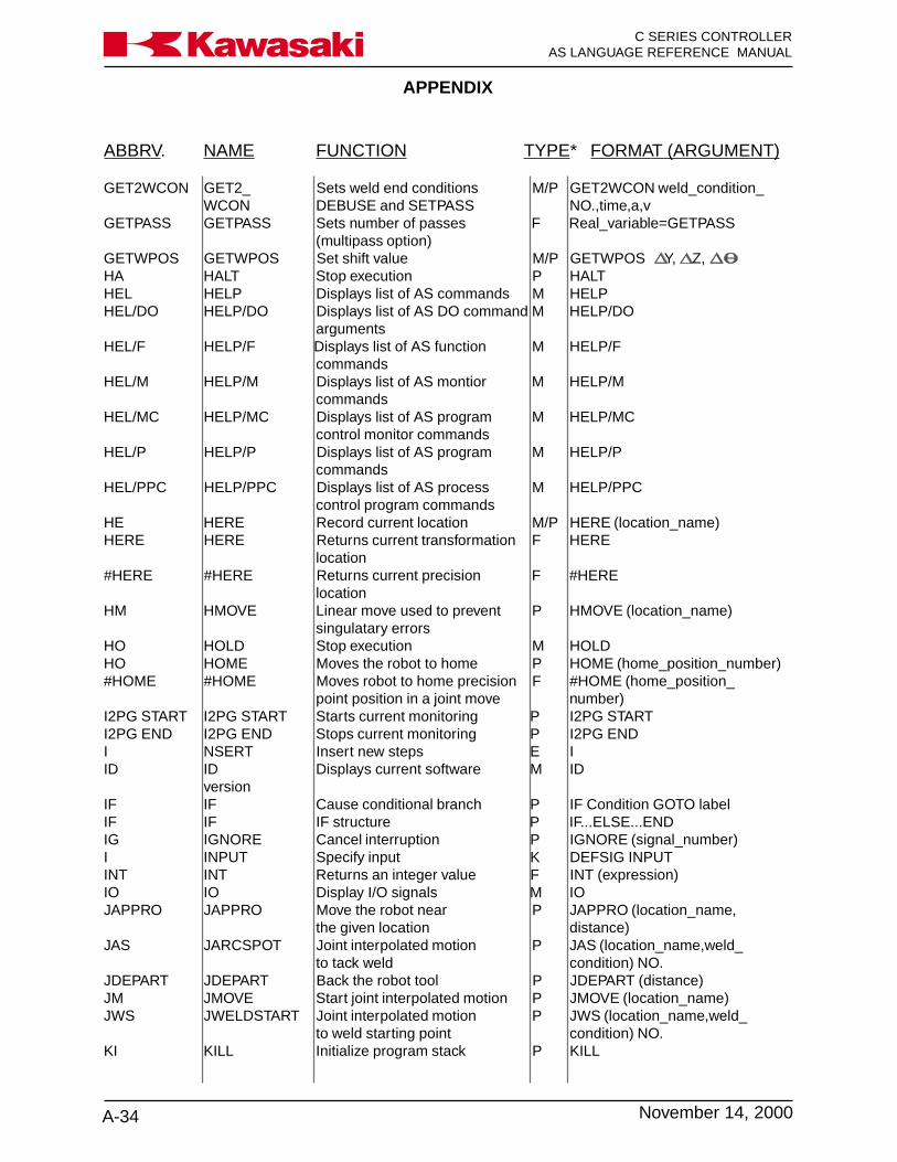
APPENDIX
C SERIES CONTROLLERAS LANGUAGE REFERENCE MANUAL
A-34 November 14, 2000
Ka a aw s k
ABBRV. NAME FUNCTION TYPE* FORMAT (ARGUMENT)
GET2WCON GET2_ Sets weld end conditions M/P GET2WCON weld_condition_WCON DEBUSE and SETPASS NO.,time,a,v
GETPASS GETPASS Sets number of passes F Real_variable=GETPASS(multipass option)
GETWPOS GETWPOS Set shift value M/P GETWPOS Y, Z,HA HALT Stop execution P HALTHEL HELP Displays list of AS commands M HELPHEL/DO HELP/DO Displays list of AS DO command M HELP/DO
argumentsHEL/F HELP/F Displays list of AS function M HELP/F
commandsHEL/M HELP/M Displays list of AS montior M HELP/M
commandsHEL/MC HELP/MC Displays list of AS program M HELP/MC
control monitor commandsHEL/P HELP/P Displays list of AS program M HELP/P
commandsHEL/PPC HELP/PPC Displays list of AS process M HELP/PPC
control program commandsHE HERE Record current location M/P HERE (location_name)HERE HERE Returns current transformation F HERE
location#HERE #HERE Returns current precision F #HERE
locationHM HMOVE Linear move used to prevent P HMOVE (location_name)
singulatary errorsHO HOLD Stop execution M HOLDHO HOME Moves the robot to home P HOME (home_position_number)#HOME #HOME Moves robot to home precision F #HOME (home_position_
point position in a joint move number)I2PG START I2PG START Starts current monitoring P I2PG STARTI2PG END I2PG END Stops current monitoring P I2PG ENDI NSERT Insert new steps E IID ID Displays current software M ID
versionIF IF Cause conditional branch P IF Condition GOTO labelIF IF IF structure P IF...ELSE...ENDIG IGNORE Cancel interruption P IGNORE (signal_number)I INPUT Specify input K DEFSIG INPUTINT INT Returns an integer value F INT (expression)IO IO Display I/O signals M IOJAPPRO JAPPRO Move the robot near P JAPPRO (location_name,
the given location distance)JAS JARCSPOT Joint interpolated motion P JAS (location_name,weld_
to tack weld condition) NO.JDEPART JDEPART Back the robot tool P JDEPART (distance)JM JMOVE Start joint interpolated motion P JMOVE (location_name)JWS JWELDSTART Joint interpolated motion P JWS (location_name,weld_
to weld starting point condition) NO.KI KILL Initialize program stack P KILL
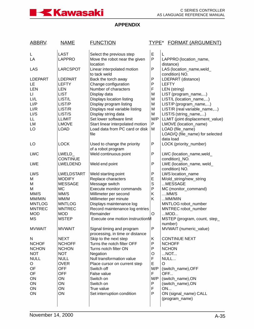
APPENDIX
A-35November 14, 2000
Ka a aw s k C SERIES CONTROLLERAS LANGUAGE REFERENCE MANUAL
ABBRV. NAME FUNCTION TYPE* FORMAT (ARGUMENT)
L LAST Select the previous step E LLA LAPPRO Move the robot near the given P LAPPRO (location_name,
location distance)LAS LARCSPOT Linear interpolated motion P LAS (location_name,weld_
to tack weld condition) NO.LDEPART LDEPART Back the torch away P LDEPART (distance)LE LEFTY Change configuration P LEFTYLEN LEN Number of characters F LEN (string)LI LIST Display data M LIST (program_name,...)LI/L LIST/L Displays location listing M LIST/L (location_name,...)LI/P LIST/P Display program listing M LIST/P (program_name,...)LI/R LIST/R Displays real variable listing M LIST/R (real variable_name,...)LI/S LIST/S Display string data M LIST/S (string_name,...)LL LLIMIT Set lower software limit M/P LLMIT (joint displacement_value)LM LMOVE Start linear interpolated motion P LMOVE (location_name)LO LOAD Load data from PC card or disk M LOAD (file_name)
file LOAD/Q (file_name) for selecteddata load
LO LOCK Used to change the priority P LOCK (priority_number)of a robot program
LWC LWELD_ Weld continuous point P LWC (location_name,weld_CONTINUE condition)_NO.
LWE LWELDEND Weld end point P LWE (location_name, weld_condition) NO.
LWS LWELDSTART Weld starting point P LWS location_nameM MODIFY Replace characters E M/old_string/new_stringM MESSAGE Message switch S ...MESSAGEM MC Execute monitor commands P MC (monitor_command)MM/S MM/S Millimeter per second K ....MM/SMM/MIN MM/M Millimeter per minute K ...MM/MINMNTLOG MNTLOG Displays maintenance log MNTLOG robot_numberMNTREC MNTREC Record maintenance log entries MNTREC robot_numberMOD MOD Remainder O ...MOD...MS MSTEP Execute one motion instructionM MSTEP (program, count, step_
number)MVWAIT MVWAIT Signal timing and program P MVWAIT (numeric_value)
processing, in time or distanceN NEXT Skip to the next step K CONTINUE NEXTNCHOF NCHOFF Turns the notch filter OFF P NCHOFFNCHON NCHON Turns notch filter ON P NCHONNOT NOT Negation O ...NOT...NULL NULL Null transformation value F NULL...O OVER Place cursor on current step E OOF OFF Switch off M/P (switch_name),OFFOF OFF False value F OFF...ON ON Switch on M/P (switch_name),ONON ON Switch on P (switch_name),ONON ON True value F ON...ON ON Set interruption condition P ON (signal_name) CALL
(program_name)

APPENDIX
C SERIES CONTROLLERAS LANGUAGE REFERENCE MANUAL
A-36 November 14, 2000
Ka a aw s k
ABBRV. NAME FUNCTION TYPE* FORMAT (ARGUMENT)
ON ON Set interruption condition P ON (signal_name) GOTO (labelONI ONI Set interruption condition P ONI (signal_number) CALL
(program_name)ONI ONI Set interruption condition P ONI (signal_number) GOTO
(label)OP OPLOG Display history of operations M OPLOGOR OR Logical OR O ...OR...O OUTPUT Specify output K DEFSIG_OUTPUTO OVER Used to overwrite program line E OOX OX Specify OX signal number P OX (signal_number)OX OX.PREOUT Sets OX signal timing S ...OX.PREOUT...P PRINT Display program steps E P (number_of_steps)PA PAUSE Suspend execution P PAUSEPCA PCABORT Stop PC program execution M PCABORTPCC PCCONTINUE Resume PC program execution M PCCONTINUE NEXTPCEN PCEND Terminate PC program M/P PCEND (program,task_number)
execution at the next STOPinstruction
PCEX PCEXECUTE EXECUTE PC program M/P PCEXECUTE (program, cycles,step_number)
PCK PCKILL Initialize PC program stack P PCKILLPCSC PCSCAN Sets PC program scan time P PCSCAN (time)PCS PCSTATUS Display PC program status P PCSTATUS (program_number)PCSTE PCSTEP Executes one step of a PC M PCSTEP (program,cycles,step_
program number)PI PI Value of pi (3.14...) F PI...PICKLOC PICKLOC Specify target location P PICLOCK (location_name)PO POINT Define location variable M/P POINT (location1=location2)PO/X POINT/X Set value to X component M/P POINT/X (location1=location2)PO/Y POINT/Y Set value to Y component M/P POINT/Y (location1=location2)PO/Z POINT/Z Set value to Z component M/P POINT/Z (location1=location2)PO/O POINT/O Set value to O component M/P POINT/O (location1=location2)PO/A POINT/A Set value to A component M/P POINT/A (location1=location2)PO/T POINT/T Set value to T component M/P POINT/T (location1=location2)PO/OAT PO/OAT Set value to O, A, T components M/P POINT/OAT (location1=location2)PO/7 POINT/7 Set value to seventh axis M/P POINT/7 (location1=location2)POWER POWER Displays status of motor power S SWITCH POWER (ON/OFF)#PPOINT #PPOINT Joint displacement value F #POINT (jt1,jt2,jt3,jt4,jt5,jt6)PR PREFETCH. Sets AS Language signal timing S ...PREFETCH.SIGINS...
SIGINSPRIM PRIME Set up program for execution M PRIME (program,cycle,step)PRIN PRINT Displays data on the selected P PRINT (device:output data,...)
screenP PRINT displays specified number of E P (number_of_steps)
program stepsPRIORITY PRIORITY Sets program run status priority F PRIORITYPROM PROMPT Prompts operator to enter data P PROMPT (device,output
character string,variable)PU PULSE Pulse output signal M/P PULSE (signal _number,time)QTOOL Q Sets type of tool used, ON block S QTOOL ON/OFF
step, OFF AS Language
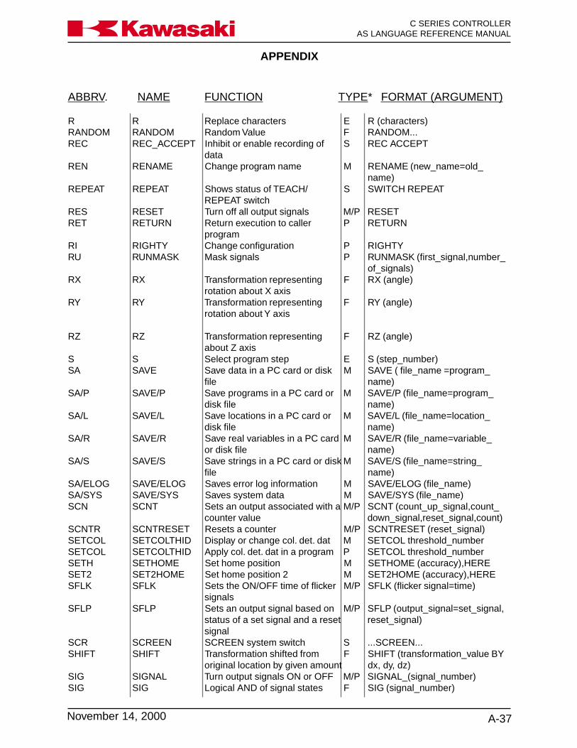
APPENDIX
A-37November 14, 2000
Ka a aw s k C SERIES CONTROLLERAS LANGUAGE REFERENCE MANUAL
ABBRV. NAME FUNCTION TYPE* FORMAT (ARGUMENT)
R R Replace characters E R (characters)RANDOM RANDOM Random Value F RANDOM...REC REC_ACCEPT Inhibit or enable recording of S REC ACCEPT
dataREN RENAME Change program name M RENAME (new_name=old_
name)REPEAT REPEAT Shows status of TEACH/ S SWITCH REPEAT
REPEAT switchRES RESET Turn off all output signals M/P RESETRET RETURN Return execution to caller P RETURN
programRI RIGHTY Change configuration P RIGHTYRU RUNMASK Mask signals P RUNMASK (first_signal,number_
of_signals)RX RX Transformation representing F RX (angle)
rotation about X axisRY RY Transformation representing F RY (angle)
rotation about Y axis
RZ RZ Transformation representing F RZ (angle)about Z axis
S S Select program step E S (step_number)SA SAVE Save data in a PC card or disk M SAVE ( file_name =program_
file name)SA/P SAVE/P Save programs in a PC card or M SAVE/P (file_name=program_
disk file name)SA/L SAVE/L Save locations in a PC card or M SAVE/L (file_name=location_
disk file name)SA/R SAVE/R Save real variables in a PC card M SAVE/R (file_name=variable_
or disk file name)SA/S SAVE/S Save strings in a PC card or disk M SAVE/S (file_name=string_
file name)SA/ELOG SAVE/ELOG Saves error log information M SAVE/ELOG (file_name)SA/SYS SAVE/SYS Saves system data M SAVE/SYS (file_name)SCN SCNT Sets an output associated with a M/P SCNT (count_up_signal,count_
counter value down_signal,reset_signal,count)SCNTR SCNTRESET Resets a counter M/P SCNTRESET (reset_signal)SETCOL SETCOLTHID Display or change col. det. dat M SETCOL threshold_numberSETCOL SETCOLTHID Apply col. det. dat in a program P SETCOL threshold_numberSETH SETHOME Set home position M SETHOME (accuracy),HERESET2 SET2HOME Set home position 2 M SET2HOME (accuracy),HERESFLK SFLK Sets the ON/OFF time of flicker M/P SFLK (flicker signal=time)
signalsSFLP SFLP Sets an output signal based on M/P SFLP (output_signal=set_signal,
status of a set signal and a reset reset_signal)signal
SCR SCREEN SCREEN system switch S ...SCREEN...SHIFT SHIFT Transformation shifted from F SHIFT (transformation_value BY
original location by given amount dx, dy, dz)SIG SIGNAL Turn output signals ON or OFF M/P SIGNAL_(signal_number)SIG SIG Logical AND of signal states F SIG (signal_number)

APPENDIX
C SERIES CONTROLLERAS LANGUAGE REFERENCE MANUAL
A-38 November 14, 2000
Ka a aw s k
ABBRV. NAME FUNCTION TYPE* FORMAT (ARGUMENT)
SIN SIN Sine F SIN (real-value_expression)...SL SLOW_REPEAT Used to reduce robot speed M SLOW REPEATSO SOUT Sets 1FS board output based on M/P SOUT (signal_number=signal_
conditional statement condition)SP SPEED Set monitor speed M SPEED (speed)SP SPEED Set program speed P SPEED (speed)_ALWAYSSQRT SQRT Square root F SQRT (real-value_expression)STA STATUS Display system status M STATUSSTA STABLE Stop the robot for the given time P STABLE (time)STE STEP Execute a single program step M STEP (program_name, count,
step_number)STI STIM Sets 1FS board timer output M/P STIM (timer_number=input_
when specified time is elapsed signal,time)STO STOP Terminate execution cycle P STOPSTP STPNEXT Used to execute the next step M STPNEXT
in a program with STP_ONCEswitch ON
ST STP_ONCE With STP_ONCE ON, a program S STP_ONCEexecutes one step at a time
SW SWAIT Wait for desired signal states P SWAIT (signal_number)SW SWITCH Set system switches M SWITCH (switch_name) =ON/
OFFSY SYSINIT Initialize system M SYSINITTDRA TDRAW Move robot by given amount in P TDRAW (dx, dy, dz)
tool coordinatesTE TEACH Teach locations with pendant M TEACH (location_name)TEACH_LOCK TEACH_LOCK Displays status of TEACH LOCK S SWITCH TEACH_LOCK
switch (ON/OFF)THEN THEN IF structure P IF (logical) THEN... ELSE... ENDTIM TIME Set date and time M TIME yy:mm:dd hh:mm:ssTIMER TIMER Set timer P TIMER (timer_number)=(time)TI TIMER Timer value F TIMER (timer_number)TO TO FOR structure K FOR...TO...ENDTO TOOL Specify tool transformation M TOOL (transformation_value)TOO TOOL Specify tool transformation P TOOL (transformation_value)TRADD TRADD Adds component of a traverse F TRADD (transformation_value)
axis to a transformation locationTRANS TRANS Transformation value F TRANS (X, Y, Z, O, A, T)TRHE TRHERE Records transformation location M/P TRHERE (location_name)
including the traverse axiscomponent
TRUE TRUE Logical TRUE F TRUETW TWAIT Wait for the specified time P TWAIT (time)TY TYPE Display data P TYPE output_data,...UL ULIMIT Set upper software limit M/P ULIMIT joint_displacement_valueU UNTIL DO structure P DO...UNTIL logicalUW UWRIST Change wrist configuration P UWRISTVA VALUE Case value statement P CASE...VALUE...ELSE...ENDW1SET W1SET Specify weld conditions M/P W1SET NO. = sp,a,v,wa,wf,pnW2SET W2SET Specify end of weld conditions M/P W2SET NO. = time,a,vWA WAIT Wait until condition is satisfied P WAIT (condition)

APPENDIX
A-39November 14, 2000
Ka a aw s k C SERIES CONTROLLERAS LANGUAGE REFERENCE MANUAL
ABBRV. NAME FUNCTION TYPE* FORMAT (ARGUMENT)
WE WEIGHT Changes servo feedback M/P WEIGHT (payload_weight)calculations to compensate formoved payload
W WHERE Display current robot location M WHERE (mode) (1-6)status
W WHILE DO structure P WHILE...DO...ENDW.INCHIN W.INCHING Set wire inching speed M/P W.INCHIN sp,timeWLIST WLIST Displays W1SET conditions M WLISTWLIST 2 WLIST 2 Displays W2SET conditions M WLIST 2XMWIRE XMWIRE Wire check P XMWIRE location_name,
inching_speed, retract_speedXF XFER Transfers data within a program M XFER (destination_program,start
or to another program step=source_program,first_step,number_of_steps)
X XMOVE Robot moves to the next P XMOVE (location) TILL (signal_location until the specified number)signal is received, thenmoves to the following location
XOR XOR Exclusive logical OR O XORZSIG ZSIGSPEC Set number of signals installed M ZSIGSPECZZE ZZERO Set/display zeroing data M ZZERO joint_number+ + Addition O ...+...- - Subtraction O ...-...* * Multiplication O ...*.../ / Division O .../...^ ^ Power O ...^...< < Less than O ...<...<= <= Less than or equal to O ...<=...== == Mathematically equal to O ...==...<> <> Not equal to O ...<>...>= >= Greater than or equal to O ...>=...> > Greater than O ...>...

GLOSSARY
G-1
Ka a aw s k C SERIES CONTROLLERAS LANGUAGE REFERENCE MANUAL
November 20, 1998
GLOSSARY ................................................................................................................ G-2
GLOSSARY
C SERIES CONTROLLERAS LANGUAGE REFERENCE MANUAL
G-2 November 20, 1998
Ka a aw s k
This glossary contains definitions of terms used by operators, programmers, and main-tenance personnel who work with Kawasaki robots. The definitions are listed in alpha-betical order.
A
• ACCELERATETo speed up a process.
• ACCURACYA measure of the difference between the commanded robot arm position and theactual position. Also identifies how well an indicated value conforms to a true value(i.e., an actual or accepted standard value).
• ACRONYMA term made up of the initial letters of words in a set phrase. For example, LED is anacronym for light emitting diode.
• ADDRESSA number that identifies a specific location in the computer’s or processor’s memory.Means of identifying a location or data in a control system.
• ADDRESSINGComputer operations store data in specific memory locations or addresses. Thelargest memory location determines the amount of data that can be stored. Thelarger the number, the larger the possible program.
• AIR CUTMoving a weld gun into position but without generating an arc.
• ALGORITHMA finite set of well-defined rules or procedures for solving a problem step-by-step.
• ALPHANUMERICPertaining to a set of symbols that contain both letters and numbers, either individu-ally or in combination.
• AMBIENT TEMPERATUREThe temperature of air or liquid that surrounds a device.
• AMPERE (AMP)A unit of electrical current flow that is equivalent to one (1) coulomb per second.One (1) volt across one (1) ohm of resistance causes a current flow that is equivalentto one (1) amp.

GLOSSARY
G-3
Ka a aw s k C SERIES CONTROLLERAS LANGUAGE REFERENCE MANUAL
November 20, 1998
• ANALOGA continuously changing electrical voltage signal. In robot systems, the magnitudeor value of the signal represents commanded robot axis motion.
• ANALOG DATAInformation that is represented by a characteristic of the value or magnitude of anelectrical signal, such as the amplitude, phase, or frequency of the voltage, theamplitude or duration of a pulse, the angular position of a shaft, or the pressure of afluid number.
• ANTI-FRICTION BEARINGA rolling element which is used to support a rotating shaft.
• ARC SENSORA sensor that detects weld lines utilizing arc characteristics.
• ARGUMENTA value applied to a procedure; data used by a function or other command. Forinstance, in the AS command JMOVE flange, 2. The variable, flange, and the clampnumber 2 are the arguments of the function JMOVE.
• ARRAYAn ordered set of addresses or their values. Elements of an array can be referencedindividually or collectively. Array elements all have the same type of data, for in-stance, integer or character, and are usually presented in rows and columns.
• ARTICULATEDTo join together permanently or semi-permanently by means of a pivot connection foroperating separate segments as a unit.
• ARTICULATED ROBOTA robot arm which contains at least two consecutive revolute joints, acting aroundparallel axes, resembling human arm motion. The work envelope is formed by partialcylinders or spheres. The two basic types of articulated robots, vertical andhorizontal, are sometimes called anthropomorphic because of the resemblance tothe motions of the human arm.
• ASCIIAn acronym for American Standard Code for Information Interchange. This standard8-bit code is used by many devices, such as keyboards and printers.
• AS LANGUAGEKawasaki robot language used to communicate commands and instructions from akeyboard to the CPU.

GLOSSARY
C SERIES CONTROLLERAS LANGUAGE REFERENCE MANUAL
G-4 November 20, 1998
Ka a aw s k
• ASSIGNMENTAn instruction used to express a sequence of operations, or used to assign operandsto specified variables, or symbols, or both.
• ASYNCHRONOUSA means of data communication where the data is sent a character at a time pre-ceded by a start bit and followed by a stop bit. No direct timing signal links the trans-mitter and receiver.
• AUXILIARY DATAInformation about a point, other than the positional data, such as speed, accuracy,weld schedule and clamp condition.
• AXISA straight line about which sections of the mechanical unit rotate (e.g., joints JT1,JT2, JT3 etc.).
B
• BACKLASHThe clearance, slack, or play between adjacent gears, or the jar or reaction oftencaused by such clearance when the parts are suddenly put in action or are inirregular action.
• BASE COORDINATEA fixed coordinate system having an origin at the intersection of the X, Y, and Z axes.
• BAUD RATEDetermines the number of bits per second (bps) or characters transmitted betweendevices.
• BCDAn acronym for binary coded decimal. The BCD 8-4-2-1 code expresses eachdecimal digit by its own 4-bit binary equivalent. The 8-4-2-1 code is identical tobinary through the decimal number 9. Above the decimal number 9 each decimaldigit is represented by its own 4-bit binary equivalent. For example, using the 8-4-2-1 binary-coded system, the number 10 is interpreted as 0001 0000.
• BINARY CODEA system in which characters are represented by a group of binary digits, that havethe value of either 0 or 1, true or false, on or off.
• BITAcronym for binary digit, having one of two values: 0 or 1.

GLOSSARY
G-5
Ka a aw s k C SERIES CONTROLLERAS LANGUAGE REFERENCE MANUAL
November 20, 1998
• BOOTThe method by which computers are brought from a non-operating to an operatingstate. During this sequence, the computer memory is usually reset. This is oftenperformed to restart the computer after a crash, to bring it on-line.
• BUFFERA temporary memory storage area in a computer or electronic device.
• BUGA problem in a software or hardware element of a system.
• BUSThe primary communication path in the controller along which internal signals aresent among processors and memories.
C
• CABLE CARRIERA device which carries cables and hoses (including power sources) from a stationarylocation to a linear moving device.
• CARTESIAN COORDINATEA location in space defined by three axes at right angles to each other, commonlylabeled X, Y, Z.
• cccubic centimeter
• CELLA manufacturing unit consisting of two or more work stations or machines, and thematerial transport mechanisms and storage buffers that interconnect them.
• CENTER OF GRAVITYThe point at which the entire weight of a body may be considered as concentrated,so that if supported at this point the body would remain in equilibrium in any position.
• CHARACTERA term that describes all numbers, letters, and other symbols typically found on acomputer keyboard.
• CHECK MODEA procedure that allows the user to check positional data and auxiliary data while inthe teach mode with the Kawasaki robot . This procedure is in many ways analo-gous to reverse point and forward point operations in other robot models.

GLOSSARY
C SERIES CONTROLLERAS LANGUAGE REFERENCE MANUAL
G-6 November 20, 1998
Ka a aw s k
• CHECKSUMA method by which the contents of data or a transmission are verified to be accurate.This method ‘sums’ all the characters and translates them into a number which isappended to the data.
• CHEMICAL ANCHORA threaded rod installed in a structure (e.g., a concrete floor) and secured by epoxy,for the purpose of securing hardware.
• CIRCULAR INTERPOLATIONA path taken by the robot that connects at least three points with an arching motion.The CPU will calculate a path that places the taught points on a section of a circle.
• CLOSED-LOOP SYSTEMA system in which a command value is output and a feedback value is returned. Theresulting error, the difference between the command and the feedback, is used tocorrect the signal. In a robot system, the command signal is output by the controller,causing the robot arm to move, and the feedback signal is produced by the encoder,which reads the current position of the arm.
• CODEA set of rules for expressing information in a language that is understood and pro-cessed by a control system.
Also, a term for instructions in a computer program. Code performs a process, anddata is the information that is processed.
• COMMANDAn analog signal, or group of signals or pulses, which cause a specified function tobe performed. An instruction or request in a computer program that performs aparticular action. Commands that are needed to run the operating system are calleda command language.
• COMMENTOptional, non-executing remarks added to a program to explain various aspects ofthe program.
• COMPILERA system task that translates a program written in source code, into binary code thatcan be understood by the processor.
• COMPOUND TRANSFORMATIONA location in the Cartesian coordinate system that is defined relative to anotherCartesian coordinate location.
GLOSSARY
G-7
Ka a aw s k C SERIES CONTROLLERAS LANGUAGE REFERENCE MANUAL
November 20, 1998
• CONTIGUOUS FILEA file that is stored in continuously adjacent areas of memory, in contrast to a filewhich is scattered to make more efficient use of disk space.
• CONTINUOUS PATH CONTROLA type of robot control in which the robot moves according to a replay of closelyspaced points programmed on a constant time base during teaching.
• CONTROL ERROR CODEA code which identifies system problems whenever an alarm condition occurs.
• CONTROLLED AXISA robot axis that is operated by electrical or hydraulic power.
• CONTROLLERAn electronic device, with processing capabilities and software, which controls therobot actions and functions.
• CONVEYER TRACKINGUsed to make the robot follow a part on a conveyor, without the use of a traverseaxis.
• COORDINATEA set of numbers that locate a point in space.
• CPUAcronym for central processing unit. A collection of hardware in a computer whichperforms all calculations, handles I/O, and executes programmed tasks.
• CRASHA situation where the computer fails to operate, due to a software or hardware prob-lem.
• CRTAn acronym for cathode ray tube. A CRT is a charge storage tube in which theinformation is written by means of the cathode ray beam.
• CURRENT LOOPA circuit in which a portion of the output is returned to modify the control circuitoutput. This circuit may be used as a limiting device, for safety protection.
• CURSORA pointer or indicator on a computer screen, that identifies the current position on thescreen.
GLOSSARY
C SERIES CONTROLLERAS LANGUAGE REFERENCE MANUAL
G-8 November 20, 1998
Ka a aw s k
• CYCLEA complete path of projectory performed by the robot for a specific application.
• CYCLOIDAL DRIVEA mechanical gear reduction unit that reduces the speed of the input and increasesthe torque capacity. The cycloidal unit consists of an internal arrangement of discsand pins that are driven by an eccentric drive cam. This type of gear reduction offerslow gear train backlash and the capability to achieve high reduction ratios from asingle contained unit.
D
• DATAA term given to information, instructions, words or symbols that are usually transmit-ted, processed, or stored as a group.
• DETENTA part of a mechanism that locks or unlocks a movement.
• DISCONNECTA switch that isolates a circuit or one or more pieces of electrical apparatus after thecurrent has been interrupted by other means.
• DEVIATION ERRORIn all mechanical devices, the actual position of the mechanical unit will lag behindthe electrical command of the controller. An allowable limit is assigned for this differ-ence. However, if the controller detects a condition where the difference betweenthis mechanical value and the desired electrical position is larger than the estab-lished value limit, the robot controller will generate a deviation error. This error issometimes referred to as a FOLLOWING ERROR in the robot industry.
• DEBUGThe process by which an operator’s program is checked for mistakes and then cor-rected.
• DECIMAL NUMBERNumbers in the base-10 numbering system, which uses the numerals 0 - 9.
• DEDICATEDA term used to describe a system resource, such as an I/O device or terminal, whichis used for only one purpose, or assigned a single function.
GLOSSARY
G-9
Ka a aw s k C SERIES CONTROLLERAS LANGUAGE REFERENCE MANUAL
November 20, 1998
• DEDICATED SIGNALA term used to describe a signal which is used for only one purpose, or assigned asingle function. Both inputs and outputs can be dedicated.
• DEFAULTA value or operation that is automatically entered by the system, if the operator doesnot specify one. Typically, the default is the standard or expected response.
• DELETEA command which will eliminate unwanted data.
• DELIMITERA character which separates a group of items or a character string, from othergroups, or which terminates a task.
• DEVICEAny peripheral hardware connected to the processor and capable of receiving,sorting, or transmitting data.
• DIAGNOSTICSFunction performed by the processor to identify and check for error conditions in therobot arm and peripheral devices.
• DIP SWITCHDIP is an acronym for dual in-line package. A set of small switches on circuit boardsthat can be set for different configurations.
• DIRECTORYA logical structure that organizes a group of similar files.
• DISKA high-speed, random-access memory device.
• DISK-BASED SYSTEMSystem in which programs and files are stored on the hard disk and are read intomemory when requested by the user.
• DISK PACKA device which is used to store additional data in a computer system, and is usuallyremovable.

GLOSSARY
C SERIES CONTROLLERAS LANGUAGE REFERENCE MANUAL
G-10 November 20, 1998
Ka a aw s k
E
• ECHOProcess in which characters that are typed on a keyboard are also displayed on thescreen or are sent to the printer.
• EDITORAn aid for entering information into the computer system and modifying existing text.
• EMERGENCY STOP (E-Stop)An immediate stop of robot motion, selected by the operator with a switch.
• ENCODERAn electromechanical device that is connected to a shaft to produce a series ofpulses that indicate the position of the shaft.
• EPROMAcronym for erasable programmable read-only memory. The contents of thismemory (computer chip) are retained, even when power to the system is turned off.Usually stores executive programs and critical system variables.
• ERROR LOGA report which contains a sequential list of system error messages.
• ERROR MESSAGEMessages displayed on the plasma screen of the robot controller, when the actionrequested by the operator could not be completed. Error messages can occur whencomponents malfunction or if an incorrect command is typed by the operator.
• EXPRESSIONA combination of real-valued variables and functions, and mathematical and logicaloperators. When evaluated, this combination yields a numeric value.
F
• FEEDBACKThe transmission of a signal from a measuring device (e.g., encoder, transducer) tothe device which issued the command signal within a closed-loop system. SeeCLOSED-LOOP SYSTEM.
• FIELD SIGNALSAll electrical signals that exit or enter an electrical panel.
GLOSSARY
G-11
Ka a aw s k C SERIES CONTROLLERAS LANGUAGE REFERENCE MANUAL
November 20, 1998
• FILEA set of related records or data elements, which are stored using one name and arearranged in a structure that can be used by a program.
• FILESPECIncludes the name, creation date and size of the specified file.
• FIXED DISKAn electromagnetic mass storage device which is not removable. Hard disks havemuch higher storage capacity than floppy disks.
• FLOPPY DISKAn electromagnetic mass storage device which can be removed and exchanged.
• FORM FEEDProcess which causes a printer to advance the paper to the top of the next page.
• FUNCTIONA formula or routine for evaluating an expression.
G
• GAINA proportional increase in power or signal value relative to a control signal. Theratios of voltage, power, or current as related to a reference or control signal input.
• GLOBALRefers to a function or process that affects the entire system or file.
• GRAY CODEA positional binary number notation in which any two numbers whose difference isone are represented by expressions that are the same except in one place or columnand differ by only one unit in that place or column.
H
• HALF-DUPLEX COMMUNICATIONData transmission between two devices, where the signal is sent in only one direc-tion at a time.
• HANDSHAKING PROTOCOLCommunication rules used for data transmissions between devices. Each devicemust recognize the same protocol in order to communicate.
GLOSSARY
C SERIES CONTROLLERAS LANGUAGE REFERENCE MANUAL
G-12 November 20, 1998
Ka a aw s k
• HANGA term which refers to the state of a computer system that seems to be inoperativewhen processing should be taking place.
• HARDSTOPA mechanical constraint or limit on motion.
• HARDWAREPhysical equipment and devices such as computer hard disk, cables, printer, etc.
• HAZARDOUS SIDEThe unsafe side of a component or panel, such as the inside of the control panelwhen power is applied and functions are being performed.
• HOLDWhen an external or an internal input is available for a hold condition, the robot willstop its motion and servo drive power will be removed from the robot. When anexternal hold reset is performed, the servo drive power will be energized.
• HOME POSITIONRefers to the starting or resting position of the robot.
• HYBRID ENCODEROn the Kawasaki robot a hybrid encoder is used to generate positional data, and iscomposed of an incremental encoder that generates incremental pulses, and anabsolute encoder that generates gray code binary data.
I
• IDAbbreviation for Identification.
• INCHINGA value that is used during the jogging process that allows the user to position therobot in small minute increments.
• INCREMENTAL CODEA digital closed loop feedback code that provides digital feedback pulses to the robotcontroller for the purpose of providing positional information. These incrementalpulses are generated by an encoder through the use of an optical disk with alternat-ing opaque and transparent bars or lines around the periphery of the disk. On oneside of the disk a light source is mounted, and on the opposite side a phototransistorWhen the disk rotates, the phototransistor is alternately forced into saturation andcutoff, producing the digital signal.
GLOSSARY
G-13
Ka a aw s k C SERIES CONTROLLERAS LANGUAGE REFERENCE MANUAL
November 20, 1998
• INPUTTransmission of an external signal into a control system.
• INTEGRATED CIRCUIT (IC)A combination of interconnected circuit elements which are within a continuoussubstrate.
• INTERACTIVE SYSTEMSystem where the user and the operating system communicate directly; the userthrough the keyboard, and the operating system via the display screen.
• INTERLOCKAn arrangement whereby the operation of one part or mechanism automaticallybrings about or prevents the operation of another.
• INTERPRETERA program that changes English-like commands into machine language. An inter-preter translates and executes one command at a time.
• INSTRUCTIONSDiscrete steps in a computer program that are commands or statements that tell acomputer to do something or identify data.
• INTEGERA whole number, a number without a fractional part such as 7, -318, or 19.
• INTERFACEThe circuitry that fits between a system and a peripheral device to provide compat-ible coupling between the two pieces of equipment.
• INTERPOLATIONThe mathematical process that the CPU utilizes to plot a path for the robot to travelfrom one position to another. A mathematical process that evaluates a number ofdependent and independent variables for the purpose of comparison and prediction.
• INTERRUPTAn external signal that halts program execution so that the computer can service theneeds of some peripheral device or subsystem.
• INTRINSIC SAFETY BARRIER (ISB)An electronic device used in robot controllers to restrict current and voltage to a safelevel.

GLOSSARY
C SERIES CONTROLLERAS LANGUAGE REFERENCE MANUAL
G-14 November 20, 1998
Ka a aw s k
• INVERTERA circuit which switches a positive signal to a negative signal, and vice versa.
• I/OAcronym for Input/Output. The interconnections through which the computer and itsperipheral devices communicate.
• IPMAcronym for Intelligent Power Module
J
• JOGA term used to describe the process in which the user moves the mechanical unitthrough interaction with the robot controller and the teach pendant. Sometimesreferred to as slewing.
• JOINT1. A term used to describe the individual axes of a robot.2. A term used to describe the jogging process in which the robot is jogged one axisat a time.
• JOINT MOVEA mode of operation in which the robot moves from one point to the next with anarching path. All axes motors (required for the move) begin and end their rotation atthe same time. The tool center point does not follow a linear path to reach the taughtposition.
L
• LABELAn identifier for a program command line. To identify an instruction, memory loca-tion, or part of a program.
• LANAn acronym for local area network. A group of computer terminals interconnected bycables, allowing communication of information via the network.
• LCDAn acronym for liquid crystal display. This type of display is made of material whosereflectance or transmittance of light changes when an electric field is applied.

GLOSSARY
G-15
Ka a aw s k C SERIES CONTROLLERAS LANGUAGE REFERENCE MANUAL
November 20, 1998
• LIMIT SWITCHAn electrical switch positioned to be switched when a motion limit occurs, therebydeactivating the actuator that caused the motion.
• LINEAR MOVEAn operation where the rate and direction of relative movement of the robot arm arecontinuously under computer control.
• LINE PRINTERA high-speed output device that prints a line at a time.
• LINE TURN-AROUNDChanging the source of transmission in half-duplex communications.
• LOGICAL OPERATIONAny of several operations that manipulate information according to the rules of logic(e.g., AND, OR, NOT, and exclusive OR).
• LMAbbreviation for linear motion.
• LOADThe weight applied to the end of the robot arm.
• LOCKOUTServing to prevent operation of a device or part of it.
• LSBAbbreviation for least significant bit.
M
• MANIPULATORAnother term for the mechanical portion of the robot system.
• MACHINE LANGUAGEA low-level computer language, usually written in binary code.
• MASS-STORAGE DEVICEAn input/output device that retains data input to it. Examples include: hard diskdrives, magnetic tapes, floppy diskettes, and disk packs.
• MECHANICAL UNITrobot (excluding controller)

GLOSSARY
C SERIES CONTROLLERAS LANGUAGE REFERENCE MANUAL
G-16 November 20, 1998
Ka a aw s k
• MEMORYAn area of the computer which stores data, either permanently or temporarily. Whena program is requested, it is first loaded into memory so it can be accessed quicklyby the processor.
• MHzAbbreviation for megahertz. One million cycles per second.
• MIRROR IMAGEA process which converts the positive and negative values of a taught path from aright-handed robot to a left-handed robot, or vice versa. The actions of the opposingrobots are then coordinated and synchronized.
• mmAbbreviation for millimeter.
• MNEMONICA term used to help the operator remember a large string of words or commands.
• MODEMA signal conversion device that modulates and demodulates data into an audiosignal for transmission.
• MOMENT OF INERTIAUsed to calculate end of arm tooling and handling weights. The sum of the productsformed by multiplying the mass of the load by the square of the distance from thetool mounting flange.
• MONITOR PROGRAMAn administrative computer program that oversees operation of a system. The ASmonitor accepts user input and initiates the appropriate response, follows instruc-tions from user programs to direct the robot, and performs the computations neces-sary to control the robot.
• MSBAbbreviation for most significant bit.
• msecAbbreviation for millisecond (0.001 seconds).

GLOSSARY
G-17
Ka a aw s k C SERIES CONTROLLERAS LANGUAGE REFERENCE MANUAL
November 20, 1998
N
• NOISEAny unwanted disturbance within a dynamic, mechanical, or electrical system.
• NULLEDAn electrical zero state.
O
• OCTAL NUMBERA numeral in the base-8 numbering system, which uses the numerals 0 - 7.
• OFF LINEA state in which communications between two devices cannot occur (e.g., between aprinter and a computer, if the printer is off line).
• ON LINEA state in which communication between two devices can occur.
• OPERATING SYSTEMA set of system tasks and commands that are entered by the operator and inter-preted and performed by the system.
• OPEN LOOPA control which does not use feedback to determine its output.
• OPERATORAny mathematical action or function. The arithmetic operators are: add, subtract,multiply, divide, modulo, and exponentiate. The relational operators are: greaterthan, less than, equal to, and their combinations. The logical operators are: AND,OR, exclusive OR, negate. The binary logical operators are AND, OR, exclusive OR,ones complement.
• OPTOAn optical isolator or level converter.
• OVERFLOWWhen a value or buffer exceeds a predefined limit.
GLOSSARY
C SERIES CONTROLLERAS LANGUAGE REFERENCE MANUAL
G-18 November 20, 1998
Ka a aw s k
• OVERTRAVELAn error condition that exists when the robot exceeds its normal software limit val-ues, and then actuates an overtravel limit switch.
• OVERVELOCITYWhen an axis exceeds a preset value for velocity.
• OX (OUTPUT EXTERNAL)Information transferred from the robot controller through output modules to controloutput devices.
P
• PARITYMethod by which errors are detected. In this method the combined binary values ofa byte are flagged as 1 or 0.
• PARSETo break a command string into individual elements, so it can be interpreted.
• PASSWORDA code, entered by the user, to permit access to protected information.
• PAYLOADThe maximum weight that a robot can handle satisfactorily during its normaloperations and extensions.
• PC PROGRAMPC is an acronym for process control. A PC program cannot contain any step thatcauses robot motion. PC programs are used to evaluate logic and variables andexecute program CALL and GOTO commands
• PERIPHERAL DEVICEHardware equipment which is external to the CPU, but that transmits and/or receivesI/O from the processor. Examples include: printer, CRT screen, or disk.
• PHASEThe angular relationship between current and voltage in alternating current circuits.In a waveform or period function, the fraction of the period that has elapsed, asmeasured from a reference point. Phase angle is determined by multiplying thephase by 360 degrees.

GLOSSARY
G-19
Ka a aw s k C SERIES CONTROLLERAS LANGUAGE REFERENCE MANUAL
November 20, 1998
• PINCH POINTAny point where it is possible for a part of the body to be injured between the movingor stationary parts of a robot and the moving or stationary parts of associatedequipment, or between the material and moving parts of the robot or associatedequipment.
• PLAAcronym for programmable logic array. Used in many servo drive circuits.
• PLAYBACKAn operation where a taught path is run for evaluation purposes.
• PLCAcronym for programmable logic controller. Usually referred to as the cell modulecontroller.
• POINT-TO-POINTA robot motion control in which the robot can be programmed by a user to movefrom one position to the next. The intermediate paths between these points cannotbe specified.
• POLARITY KEYSThese teach pendant or multi function panel keys allow the user to jog or slew therobot in the Joint, Base (XYZ), or Tool coordinates system.
• PORTThe connection point of an opening or passage that is usually located outside thehousing of a device.
• POSITIONAL DATAThe location in space of the robot manipulator.
• POUNCE POSITIONA positional location at a point near the workpiece, clear of the transfer mechanismand part, from which the robot is ready to begin production.
• PRINTED CIRCUITAn assembly of electronic elements that provide a complete path of electrical currentthrough conductive material deposited between terminals on an insulated surface.
• PRECISION POINTThe play back of robot location based on the angular position of the six axes, jointangles.
GLOSSARY
C SERIES CONTROLLERAS LANGUAGE REFERENCE MANUAL
G-20 November 20, 1998
Ka a aw s k
• PRINTINGA process in which characters are stamped on a surface, usually paper.
• PROGRAMA predefined, step-by-step set of instructions that are entered into a computer so aspecific process can be performed repeatedly without reentering all the steps. Robotpaths are stored and run as part of programs.
• PROGRAM EDITModification of an existing program.
• PROCESSORGenerally, any hardware or software system for carrying out programs and acting ondata.
• PULSE WIDTH MODULATION (PWM)A modulation process in which the instantaneous sampling of the modulating wave iscaused to modulate the duration of the pulse. This type of modulation is also re-ferred to as pulse duration modulation (PDM), or pulse length modulation (PLM).
R
• RAMAcronym for random access memory. An area used by the CPU for processing andtemporarily loading programs so they can be accessed quickly. The contents ofRAM are lost when the computer is powered down, unless battery backup is pro-vided.
• REAL NUMBERA number with a fractional part, such as 1.75, -31.89, .5, -4.00, etc.
• REAL-TIMEThe actual time during which the computer analyzes and processes data: informa-tion is usually processed as it is received.
• REAL VARIABLEAS language term for a variable that has had a real value assigned to it.
• REPEAT MODEA mode of operation that allows the user to check positional and auxiliary informa-tion at a selected speed value, in a continuous or a step by step type of movement ofthe mechanical unit.

GLOSSARY
G-21
Ka a aw s k C SERIES CONTROLLERAS LANGUAGE REFERENCE MANUAL
November 20, 1998
• REPEATABILITYThe measurement of the closeness of agreement among repeated measurements ofthe same variable under the same conditions.
• REWRITE MODEA mode of operation which allows the user to rewrite positional, or auxiliary data,and to insert or delete step address locations.
• RISCAcronym for reduced instruction set computer.
• ROM (read-only memory)
A memory device which is programmed at the factory and whose contents thereaftercannot be altered.
• RS-232CAn ASCII specification for connections and communication between serial devices.
• RUNA mode of operation that allows the user to select servo motor power to provide driveenergy to the robot, allowing it to perform such modes of operation as teach, check,repeat, and rewrite.
S
• SAFETY PLUGA device used with safety fencing to interlock the opening of the fence with theremoval of power to the robot.
• SCROLLWhen more information exists than can be displayed on one screen, the operatorcan move up and down through the data to view it. When data is scrolled to thescreen, the information previously viewed moves up off the screen, and new informa-tion enters the screen from the bottom.
• SENSORA device used to detect various conditions: proximity, heat, pressure, etc. An electri-cal signal from the sensor can be used to communicate information to a robot pro-gram.
• SERIALA method of transmitting data by which only one bit is sent or received at any one
GLOSSARY
C SERIES CONTROLLERAS LANGUAGE REFERENCE MANUAL
G-22 November 20, 1998
Ka a aw s k
point in time.• SEQUENTIAL ACCESS
A method used by many computers whereby data is read in the order in which it isphysically stored.
• SINGULARITY POSITIONWhen the robot is processing a linear or circular move and two or more joints are inalignment. The CPU can not process the ambiguity of a singularity configuration andan error is generated.
• SOFTWARE LIMITSProgrammed values that are included in a program at the point before a mechanicaldevice hits an overtravel limit switch or a hard limit.
• SOFTWAREA set of written programs and instructions that are executed by a computer system.
• SOURCE CODEA program that contains the actual software instructions entered by the user, incontrast to object code which is source code that has been translated into a lan-guage which can be interpreted by the computer.
• STRINGA series of characters that have been entered in a distinct sequence that can beinterpreted as a valid statement or command.
• STROKEThe movement in either direction of a mechanical part having a reciprocating motion.The entire distance passed through in such a movement.
• SUBSCRIPTA set of numbers that identifies an element of an array.
• SUBROUTINEA set of instructions that is run by another routine.
• SYMBOLA character or design that has a distinct meaning and/or is associated with some-thing.
• SYNTAXThe proper way in which commands and phrases should be typed in order to beunderstood by the control system. If the operator incorrectly types a command (i.e.,misspelled or invalid characters), a syntax error message will be displayed.
GLOSSARY
G-23
Ka a aw s k C SERIES CONTROLLERAS LANGUAGE REFERENCE MANUAL
November 20, 1998
• SYSTEM DATAData that is specific to a individual robot. Zeroing data, upper and lower softwarelimits, and software switch settings are all examples of system data.
• SYSTEM SWITCHSoftware switches that are set to determine various configurations and characteris-tics of the robot system performance.
T
• TEACH MODEA mode selected on the operator panel, during which robot arm axes positions canbe taught by the operator and are recorded by the robot.
• TEACH PENDANTA hand-held, portable device used by the operator during teach and jogging opera-tions.
• TOOL COORDINATESA Cartesian coordinate system in which the origin point is at the face plate of therobot and the orientation of the tool can be expressed in terms of a 3-dimensionalspace representation of X, Y, and Z projections.
• TOOL MODEA mode of operation in which all motions are calculated to maintain the orientation ofthe tool in space.
• TORQUESomething which produces or tends to produce rotation or torsion and whoseeffectiveness is measured by the product of the force and the perpendicular distancefrom the line of action of the force to the axis of rotation.
• TRANSFORMERA device to convert the current of a primary circuit into variations of voltage andcurrent used in secondary circuits.
• TRANSFORMATIONA mathematical description of a location that defines the position and orientation ofthe location without regard for the configuration of the robot when it is at that loca-tion.
GLOSSARY
C SERIES CONTROLLERAS LANGUAGE REFERENCE MANUAL
G-24 November 20, 1998
Ka a aw s k
• TRAP POINTsee pinch point
• TTLAcronym for transistor-transistor logic.
• TWO’S COMPLEMENTA means of representing a negative number as one more than the binary comple-ment of the absolute value of the number.
• TRIANGULAR WAVEFORMA waveform that has the shape of a triangle and is used in determining samplingvalues for servo drive circuits that utilize pulse width modulation.
U
• UHFAcronym for ultra-high frequency.
V
• VARIABLEThe name of a memory location or stored value. A variable can refer to a scalar oran array.
• VELOCITY COMMANDThis analog signal is directly proportional to motor speed, and provides the initialsignal that is processed by the servo drive system to drive a servo motor.
• VELOCITY ERRORWhen the robot controller detects an axis that has exceeded a preset value forvelocity, the robot controller will E-stop the robot.
• VOLTA unit of electrical potential difference and electromotive force. One volt is equiva-lent to the force required to produce one amp of current through one ohm of resis-tance.
W
GLOSSARY
G-25
Ka a aw s k C SERIES CONTROLLERAS LANGUAGE REFERENCE MANUAL
November 20, 1998
• WORK ENVELOPEThe effective range or reach of a robot’s axes.
• WORLD COORDINATESA Cartesian coordinate system in which the origin point is near the base of the robot,and robot movement can be expressed in terms of a 3-dimensional space represen-tation of X, Y, and Z projections.
• WRITEIn computer systems, a process in which information is output to and stored by adevice or area in memory.
• WS (WELD SCHEDULE)Data that is stored in the weld controller and provides the specific current, clamppressures, etc. for spot welding applications.
• WX (WAIT EXTERNAL)The wait external signal is one of many inputs that are processed by the robot con-troller. When the robot encounters a wait external condition, the robot will ceasemotion and the servo power will be removed.
Z
• ZEROINGThis procedure provides the robot controller with encoder data that is referencedfrom a known mechanical position (zeroing witness marks, in simple zeroing, orinclinometer values in precision zeroing) and then establishes an encoder value forthis known position. Two methods can be used, simple and precision zeroing. Somerobot manufacturers call this procedure mastering or calibration.

C SERIES CONTROLLERAS LANGUAGE REFERENCE MANUAL
INDEX
IN-1November 14, 2000
Ka a aw s k
INDEX ......................................................................................................................... IN-2

INDEX
C SERIES CONTROLLERAS LANGUAGE REFERENCE MANUAL
IN-2 November 14, 2000
Ka a aw s k
Symbols
#DEST, 6-9, 6-15#HERE Function, 6-141FS (RI/O) Board, A-21FS Board, A-141FS Circuit Board, A-21GA Board, A-2
A
Abnormal Check Sum, 4-55ABORT, 4-26, 4-30ABORT Command, 7-5Absolute Encoder, 4-49Accuracy, I-3, 2-7After Wait Timer Switch, 1-5After.Wait.TMR. system switch, A-19Allen Bradley, A-14Analog Outputs, A-2ANGLES, 1-7ANSI/RIA, 2-2Arithmetic Functions, 6-16Arithmetic Operators, 1-18Arm ID Board, 4-62ARMIOSET, 4-62, 4-64Arrays, 1-13, 1-16AS Monitor Software, 8-3ASC, 6-6ASCII Character, 1-6, 6-2ASCII Value, 1-13, 6-6Auto Servo Timer, 4-54AUTOSTART.PC System Switches, A-18AUTOSTART.PC, 1-5AUTOSTART2.PC, 1-5AUTOSTART3.PC, 1-5AUX 114 Clamp Specifications, 10-12AUX 114-41 Max Abrasion Moving/Fixed[mm],10-32Aux 149, 4-66AUX Function 181, A-12Axes, 4-51
B
BASE, 4-31, 4-37BASE Function, 6-7Base Transformation, 4-38BATCHK, 4-51Binary Operator, 1-19Binary Signal, 6-2Bit Pattern, 6-2BITS, 4-56, 4-58, 6-3BITS Command, 7-14
BNC Connectors, A-14, A-15Brake Release Switches, 2-8Brakes, 2-5, 2-8, 2-9BREAK Command, 7-13
C
CALL Command, 7-14CASE OF Command, 7-16Center of Gravity, 4-66, 4-81CHANGE, 4-11Character Strings, 1-15CHECK Key, 7-4CHSUM, 4-55Clear Check Sum Error, 4-55CMOS RAM, I-3COLCAL Command, 4-81COLINIT Command, 4-82Collision Detection AS Language Commands,4-73, 4-86Collision Detection Error, 4-85Collision Detection Function, 4-66Collision Detection Troubleshooting, 4-85COLMV Command, 4-80COLR Command, 4-74, 4-76COLRJ Command, 4-77, 4-78COLSTATE Command, 4-83COLTJ Command, 4-79Comment, 7-3Compound Transformation, 4-32, 7-10, 7-12Compound Transformations, 1-10Config.Sys, 8-5CONTINUE, 1-2, 4-26, 4-30Control Flow Structure, 7-14, 7-18Control-Net, A-13Control-Net Diagram, A-14Control-Net Topologies, A-14COPY, 4-12, 4-14, 4-21Counter Status, A-9CP Switch, 1-3CTL+L/CTL+N Key, 4-4CUT, 4-12Cycle Start, 7-4Cycle Stop Switch, 1-3
D
Data Editing, I-4Data Highway Plus, A-15Date, 4-47DECOMPOSE, 1-16Dedicated Signal, 4-59Dedicated Signals
Inputs, I-5Outputs, I-5

C SERIES CONTROLLERAS LANGUAGE REFERENCE MANUAL
INDEX
IN-3November 14, 2000
Ka a aw s k
DEFSIG, 4-56, 4-60DELETE, 4-8, 4-14Delete, 4-19, 4-26DELETE/L, 4-14, 4-20DELETE/P, 4-14, 4-19DELETE/R, 4-14, 4-20DELETE/S, 4-14, 4-20DEST, 6-9, 6-15Detection Level Setting, 4-67DEXT Format, A-19Dimensions, I-6DIRECTORY, 4-15DIRECTORY/L, 4-14, 4-16DIRECTORY/P, 4-14, 4-16DIRECTORY/R, 4-14DIRECTORY/S, 4-14, 4-17Discrete Hard Wired Systems, A-2DISPIO_01, 1-6DISPLAY, 4-13DISTANCE, 1-7, 6-5Distance Calculation, 6-5DLYSIG, 4-57DO, 1-2, 4-26, 4-31DX, 6-5DY, 6-5DYLSIG, 4-56DZ, 6-5
E
Editor Commands, 4-5Editor Mode, 1-2EMERGENCY STOP, 2-5, 2-6, 2-7, 2-9EMERGENCY STOP Switch, 3-2, 3-8, 7-5ENCCHK_EMG, 4-51ENCCHK_PON, 4-52Encoder, 4-49Encoder Abnormality Error, 4-52Encoder Deviation, 4-52Encoder Value, 4-49END Command, 7-14, 7-15, 7-18ENV_DATA, 4-54ENV2_DATA, 4-55, 8-5ERESET, 4-47, 4-48ERRLOG, 4-43ERROR CODES/TROUBLESHOOTING, 10-2Error Condition, 4-43Error Messages, I-5Error Recovery, 10-2Error Start PC Switch, 1-5ERRSTART.PC System Switch, A-18EXECUTE, 1-2, 4-26, 4-28, 7-4Execution Status, 6-7
EXIT, 4-11Expressions, 1-19
F
Failure Prediction Function, 4-65Failure Prediction Function Setup Procedure, 4-65FALSE, 6-2FC06N/FS06N/FW06N/FS10C, Work Envelope,2-12FDELETE, 4-22, 4-26FDIRECTORY, 4-22, 4-23Fiber-Optic, A-15Files, 4-23Floppy Disk, 4-23Flowcharting, 7-6FORMAT, 4-22, 4-23FRAME, 6-9FREE, 4-45FS02N/FS03N, Work Envelope, 2-10FS06L, Work Envelope, 2-11FS10E, Work Envelope, 2-14FS10L, Work Envelope, 2-15FS10N, Work Envelope, 2-13FS20C, Work Envelope, 2-16FS20N, Work Envelope, 2-17FS30L, Work Envelope, 2-18FS30N/FS45C, Work Envelope, 2-19FS45N, Work Envelope, 2-20Functions, 6-2
G
GOTO Command, 5-22, 7-13
H
HERE, 4-31, 4-32HERE Function, 6-14HOLD, 4-26, 4-30HOLD/RUN SWITCH, 3-8HOLD/RUN Switch, 3-2, 3-7, 3-8HOME, 7-13HOME position, 4-40
I
I/O Signals, I-4, 4-49, 4-58I2PG Command, 4-65IF THEN Structure, 5-48, 7-18Inertia Moment, 4-66, 4-81Initialize, 4-47Input Signals, 6-3INSERT, 4-7INT Function, 6-6
INDEX
C SERIES CONTROLLERAS LANGUAGE REFERENCE MANUAL
IN-4 November 14, 2000
Ka a aw s k
Integer Value, 6-6Integers, 1-12IO, 4-56
J
Joint Angle, 4-39
K
KCMON, 8-3KCWIN, 8-3KILL, 4-26, 4-31
L
Label, 7-3, 7-13Ladder Logic, A-2LAST, 4-7Last Weld Data, A-11LAST WELD DATA Screen, A-11LEN, 6-6Limit Switches, 2-9LIST, 4-17List, 4-17LIST/L, 4-14, 4-18LIST/P, 4-14, 4-17LIST/R, 4-14, 4-18LIST/S, 4-14, 4-18LLIMIT, 4-31, 4-39LOAD, 4-22, 4-25Load Mass, 4-81Location, 4-16Location Variables, 1-14Locations, 1-8LOCK Command, A-19Logical Operator, 1-18Logical Values, 1-12
M
Mainline Program, 7-13Maintenance Log, 4-62Mass, 4-66MC Command, A-18Memory, 4-45Memory Capacity, I-3MESSAGES, 1-5MNTLOG, 4-62, 4-64MNTREC, 4-62MODIFY, 4-9Monitor Commands, 1-6, A-18MONITOR Mode, 4-3Monitor Mode, 1-2Motion Instruction, 4-29
Motor Power Lamp, 3-7Motor Power Lamps, 3-2Motor Power Push Button, 3-7MSHA, 2-4MSTEP, 1-2, 4-26, 4-29Multi Function Panel, I-6, 2-9
N
Next, 4-30NIOSHA, 2-4Node Adapter Chip (NAC), A-12Notations And Conventions, 1-6NTCHON and NCHOFF commands, A-18NULL, 6-9, 6-12Null Base, 4-37Null Tool, 4-36NULL Tool Center Point, 7-12Numerical Expression, 1-17Numerical Information, 1-12
O
OFF, 4-47ON, 4-47Operator, 1-17OPLOG, 4-43OSHA, 2-2, 2-4Output Signals, 4-56, 6-3OX Preout Switch, 1-3
P
Parallel I/O, A-2PASTE, 4-12PASTE Reverse Order, 4-13PC Interface, 8-2PC Program, 7-2PC Program Instructions, 9-2, A-20PCABORT Command, 7-5PCCONTINUE Command, 7-5PCEND Command, 7-5PCEXECUTE Command, 7-5PCMCIA Slot, 8-5PCSTATUS Command, 9-2Play-back Mode, 1-2PLC, A-13PLC(NAC), A-12POINT, 4-31, 4-33POINT/OAT, 4-31, 4-35POINT/X, 4-31, 4-35POINT/Y, 4-31, 4-35POINT/Z, 4-31, 4-35Power On/Off Procedures, 3-2Power Requirements, I-6
C SERIES CONTROLLERAS LANGUAGE REFERENCE MANUAL
INDEX
IN-5November 14, 2000
Ka a aw s k
Precision Location, 1-8, 4-32, 6-14Precision location, 1-13, 1-14Precision Locations, 1-8PREFETCH.SIGINS, 1-4PRIME, 4-26, 4-27PRIME Command, 7-4PRINT, 4-6PRIORITY Function, A-19Process Control Programs, A-18Program and Data Control Commands, 4-14PROGRAM CHANGE, 4-53Program Control, 4-26Programmable Logic Controllers (PLCs), I-2PULSE, 4-56Pulse Command, 7-18PWM, A-18
Q
QTOOL Switch, 1-4, 7-10
R
Range of Threshold, 4-67Real Numbers, 1-12Real Values, 1-12Real Variable, 4-16Real Variables, 1-14REC_ACCEPT Switch, 4-53RECORD, 1-20Relational Operator, 1-18Remote Input/Output, A-2RENAME, 4-14, 4-20Repeat Once Switch, 1-4REPLACE, 4-10RESET, 4-59RETURN Command, 5-24, 7-20RG-6 Coaxial Cable, A-15RI/O Monitor, A-7RI/O Signal Status, A-8RISC CPU, I-3Robot Control Program, 7-2Robot Controller Design Specifications, I-3Robot Location, 4-41RPS, 1-5RS-485, A-2RS232C, 8-2RSLinx, A-14RSView, A-14
S
S-LOGIC Monitor Screen, A-10S-LOGIC Status Screen, A-12Safety Features, 2-9
SAVE, 4-22, 4-23SAVE/ARC, 4-22SAVE/L, 4-22, 4-24SAVE/P, 4-22, 4-24SAVE/R, 4-22, 4-24SAVE/S, 4-22, 4-25SAVE/SYS, 4-22Scientific Notations, 1-12SCREEN, 1-5Serial Interface, 8-2Servo Motor Power-on Procedures, 3-7SET2HOME, 4-40SETCLAMP, 4-47SETCOLTHID, 4-82SETHOME, 4-31, 4-40Setting Threshold, 4-68Setting Tool Weight Data, 4-66SHIFT, 6-9, 6-13SIGNAL, 4-56SIGNAL Command, 4-56, 7-13, 7-14 SIGNAL NUMBER, 1-7Signal Number, 4-56Signal Numbers, 4-59Signal Timing, 1-3SLOGIC, A-2SLOGIC Program Name, A-2SLOGIC Programming, A-2SLOGIC Programs, 7-2SLOW_REPEAT Switch, 4-52Small Teach Pendant, 2-6, 2-7, 2-9Software Features, I-4Software Limit, 4-39Special Features, I-5SPEED, 4-26Speed, I-4SPG Program, A-2SRAM, 4-51SRAM PC Cards, 8-5STATUS, 4-44Status, 4-43STEP, 1-2, 4-6, 4-26, 4-28STEP Command, 4-28, 7-4Step Number, 7-3Step Once Switch, 1-5Stopping Robot Motion, 7-5Stopping the Robot, 3-8String Variable, 4-17String Variables, 1-15SWAIT Command, 5-27, 7-18SWITCH, 4-47, 4-48Switch Settings, 4-48SYSINIT, 4-47System Switch, 4-48
INDEX
C SERIES CONTROLLERAS LANGUAGE REFERENCE MANUAL
IN-6 November 14, 2000
Ka a aw s k
System Switches, 1-2
T
Taps, A-15TEACH, 1-20, 4-31, 4-33Teach Lock Switch, 3-7Teach Pendant, I-6TEACH/REPEAT Switch, 3-7, 3-8Terminal Control, 4-4TIME, 4-47Time Delay, 10-67TIMER, 6-2, 6-4Timer and Counter Status Screens, A-9TIMER Command, 6-4, 7-18TIMER Status, A-9TOOL, 4-31, 4-36Tool, 4-36Tool Changer, 10-72Tool Dimensions, 1-4, 7-10TOOL Function, 6-7TOOL NULL Command, 6-12, 7-10TRANS, 6-9, 6-12Transformation, 1-8Transformation Location, 1-13, 1-14, 4-32Trap Points, 2-4Traverse Axis, A-17Trigger Keys, 2-6, 2-7Troubleshooting Flowcharts, 10-84TRUE, 6-2
U
UB150, Work Envelope, 2-21ULIMIT, 4-31, 4-39Universal Remote I/O, A-15UT100/150/200, Work Envelope, 2-22UX100/120/150, Work Envelope, 2-24UX200, Work Envelope, 2-25UX300, Work Envelope, 2-26UX70, Work Envelope, 2-23UZ100/120/150, Work Envelope, 2-27
V
VALUE Statements, 7-14Values, 1-6Variable Names, 1-13Variable Types, 1-13
W
WAIT Command, 5-26, 7-14WEIGHT Command, 4-81
Welding Clamp Subroutine, 7-18WHERE, 4-31, 4-41WHERE 1, 4-41WHERE 2, 4-41WHERE 3, 4-41WHERE 4, 4-41WHERE 5, 4-41WHERE 6, 4-41Windows™, 8-5Windows NT/95, A-14Work Cell, 2-2, 2-4Work Envelope, 2-4, 2-5, 2-6, 2-7, 2-8Work Envelope Drawings, 2-10
X
XD, 4-12XFER, 4-14, 4-21XP, 4-12XQ, 4-13XS, 4-13XY, 4-12
Z
ZD130, Work Envelope, 2-28Zeroing Data, 4-49ZSIGSPEC, 4-47, 4-49ZX130L, Work Envelope, 2-29ZX130U, Work Envelope, 2-30ZX165U, Work Envelope, 2-31ZX200S, Work Envelope, 2-32ZX200U, Work Envelope, 2-33ZX300S, Work Envelope, 2-34ZZERO, 4-47, 4-49, 4-50