karting engines s60 k60 w60 s80 k80 w80 - comer - top- kartcomertopkart.pl/maintenance.pdf ·...
TRANSCRIPT

Operation,mainteance andsafety manual
Operation,mainteance andsafety manual
Karting EnginesS60 K60 W60 S80 K80 W80
CPP K85 K100 K125 K98
Karting EnginesS60 K60 W60 S80 K80 W80
CPP K85 K100 K125 K98
Comer SpA reserves the right to revise the information and illustrations in this manual without advance notice.
Congratulations on your purchase of a precision manufactured Comer engine.It is designed to give you long and dependable service. To obtain maximum performance andsatisfaction from your Comer engine, it is important that you read and fully understand theoperation, maintenance and safety instructions in this manual before using your engine. It is alsoimportant that you allow only persons who understand these instructions to operate the engine.Contact your Comer dealer if you do not understand any of the instructions in this manual.
SYMBOLSPay attention to the symbols used in this manual.It show you dangerous situations for you or foryour new engine.
Danger personal injury
Danger mechanical injury
Watch out!
GENERAL INFORMATIONImportant/Caution:Start the engine only in a well-ventilated area.The exhaust emissions are hazardous to yourhealth.Always wear proper clothing when performingmaintenance on your engine.Use caution when handling fuel. Avoid skincontact and avoid inhaling fuel vapor.
Never touch moving parts when the engine isrunning. Do not touch the muffler. It is Hot! Donot touch the spark plug or cable. It could causedangerous electrical shock!Never pull the starter cord with the plastic cap inspark plug hole. The engine compression couldcause the cap to blow out and cause injury.Always use original Comer replacement partsand the proper tools when working on your Comerengine.Proper fuel mix is necessary for optimum enginelife and performance. See Technical Specificationsection for the proper fuel mix.
GENERAL TECHNICAL SPECIFICATIONS
Cylinder DisplacementCylinder BorePiston StrokeIgnition SystemIgnition TypeIgnition TimingSpark Plug GapFuel Mixture 20 to 1, gas to oil, (7
ounces of oil to 1 U.S. gallon of gas)
Engine WeightTorque Specifications
SPECIAL TECHNICAL SPECIFICATIONSFOR HOMOLOGATED ENGINESRefer to homologation sheet for your country.

BEFORE THE USE
PACKAGINGYour engine will arrive in a box marked with the Comer modeltype and serial number on the outside. Inside will be the enginecomplete with carburetor, air filter, muffler and clutch. For modelsusing the Veyvey muffler, only the exhaust header is included. The Veyveymuffler is packed separately.
ENGINE MOUNTING/CHASSIS ASSEMBLYPlease these read instructions carefully before beginning to mount engine onchassis.
-Unpack the engine. Remove anypackaging material remaining onthe engine. Place the engine on itsside on a clean, flat surface. Cleansurfaces of the engine base andmounting plate. Attach the plateto the engine base with four 8 mmAllen screws using a 6mm Allenkey. See Figure 1.
-Rest the engine, with mount, on thechassis. Tighten the engine mountclamps enough to hold the enginein position. Do not tighten com-pletely. See Figure 2.
1
2
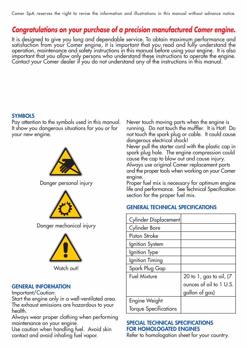
-Align the axle sprocket with theengine sprocket. Install chain ofproper length (length varies withtype of kart and gear size). SeeFigure 3.
-To adjust chain tension, move the engine ahead untilthe proper tension is reached. Proper tension allows1 cm. of movement. Tighten mount clamps completely.Re-check chain tension. See Figure 4.
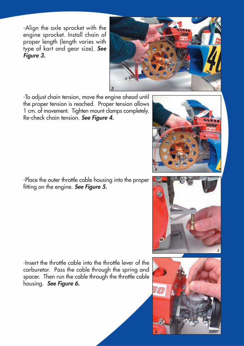
-Place the outer throttle cable housing into the properfitting on the engine. See Figure 5.
-Insert the throttle cable into the throttle lever of thecarburetor. Pass the cable through the spring andspacer. Then run the cable through the throttle cablehousing. See Figure 6.
4
5
6
3

-Pull the cable through until it stops at thethrottle lever of the carburetor. See Figure 7.
-Pass the free end of the throttle cable to the throttlestop near throttle pedal. Make sure that there is aclamp installed on the throttle cable.
-Pass the cable through the weldedring on the throttle pedal. Then loopit around and attach it to the throttleclamp by running it through the holein the clamp.See Figure 8.
-Adjust the throttle cable by usingthrottle clamp and the pedal stopon the chassis so that the pedal stopsat the point where the throttle is fullyopen. Do not stress the throttle lever.
-Insert the fuel line into the top cap of the carburetor.
-Remove the plastic cap from the spark plug hole. Lightly oil the spark plugthreads. Finger-tighten the spark plug in the hole.
-Next tighten and loosen the plug two or three times to allow the gasketon the plug to seat. Then tighten the plug securely. Then cover thespark plug with the spark plug cap.
For engines with a Veyvey muffler, the following additional stepsare required:
-Install the header pipe into the engine with two studsor Allen screws. In some models, the header pipehas already been installed.
-Insert the flex into the header pipe. Theninsert the muffler on the other end of theflex. Place the muffler in the exhaustcradle that is assembled on thechassis.
7
8

-Fasten the muffler and header pipeusing two or three springs (thenumber of springs needed dependson the model). Use a spring toolto insert one end of a spring in onehole of the exhaust flange. Usingthe spring tool, pull the other endof the spring through one of thehole on the exhaust flange on themuffler. See Figure 9.
-Repeat this process with the remaining spring(s).
-Use a spring tool to fasten themuffler on the cradle assembly withthe two springs provided.See Figure 10.
Important/Caution:To prevent injury, protect your hands andeyes with appropriate gloves and safetyglasses when installing the muffler.
9
10

STARTING AND BREAK-IN
GENERAL INFORMATION:-We're sure you are excited about getting your kart out on thetrack. But we would like to remind you that only a proper break-in will insure the best performance of your engine in the future andguarantee its long and trouble-free operation.
-Break-in is required when an engine is new or has undergone a major serviceof the engine's main parts (pistons, rings, cylinder or crankshaft). Not all Comerengines required the same break-in time. There is a tag on the engine next tothe spark plug cap that will provide break-in times for your engine.
Fuel Preparation:-Prepare fuel by mixing one U.S. gallon of gasoline with 7 ounces of oil. The Comerengines use unleaded commercial gasoline (pump gas). Shake the can thoroughlyto mix the fuel. Then fill the gas tank.
Important/Caution:-Follow these rules to prevent personal injury. Gasoline is flammable and explosive. Whenworking with fuel, never smoke or use it near fire. Work in a well-ventilated area or outside. Do not inhale gas vapors and avoid contact with your skin.-Follow these rules to prevent damage to your engine. Be precise in the oil to gas ratiowhen mixing fuel. A mistake in measurements could result in engine failure.
Carburetor Adjustment:-For the initial start, set both low-speed and high-speed jets on thecarburetor at one turn out.
Starting the Engine:-The starter has an inertial type cord assembly thatretracts automatically. To start the engine, follow thesesteps:
-Turn the "ON/OFF" switch, which is located on theengine cover, to the "ON" position.
-Pull firmly on the starter handle. At the sametime, close the choke lever on the carburetor.See Figure 11.
11

-When the engine starts, release thechoke lever. Run the engine and accelerate inter-mittently to higher RPMs. Do not accelerate to full throttle.
-After a few minutes of warm up, proceed onto the track. Runthe engine by alternating a few seconds on the throttle and off thethrottle. Continue this way for 5-6 laps.
-Increase the duration and extent of acceleration for another 15-20 minutes.
-Continue for the time indicated on the run-in table attached to the spark plugwire. Intermittently open the accelerator completely for a few seconds and thenrelease it.
Important/Caution:Do not initiate the break-in on a chassis stand. Do not hold the throttle at a constant speed.
MAINTENANCE INSTRUCTIONS
When to Perform Maintenance:Follow the schedule shown below:
Carburetor Service after 6 hoursDiaphragm Change after 18 hoursSpark Plug Change after 10 hoursMuffler Internal cleaning after 10 hoursClutch Change after 10 hoursComplete Piston Change after 15 hoursAssembly (Piston,rings, pin & circlips)Chain Change after 20 hoursThrottle Cable Change after 30 hoursCylinder Change after 60 hoursRod Change after 60 hours

How to perform the maintenance:
Carburetor/Diaphragm:-Disconnect the throttle cable fromthe carburetor. Unscrew the car-buretor with a 10mm wrench.Remove the air filter and the cover.Clean them with gasoline or clea-ning solvent. See Figure 12.
-Unscrew the fuel filter cap. Cleanthe filter and its seat with compressedair. Check the cork gasket and re-place if necessary. See Figure 13.
-Remove the 6 screws of the car-buretor body with a 2mm Thorsenkey. Clean the parts, openings andpassages with compressed air orcleaning solvent. Change the gasketand diaphragm, making sure thatno residues are left on either thecarburetor plates or the main body.See Figure 14.
-Remove the screw supporting thefulcrum arm pin. Check to assure fulcrumarm is working freely. Remove the valveseat with an 8mm socket. Clean the insideof the valve with compressed air before youreassemble it. See Figure 15.
-To reassemble the carburetor, follow theabove steps in reverse order.Comer recommends removing any remaininggasoline from the carburetor at the end ofeach practice session or race in orderto avoid damage to the gasket ordiaphragm.
13
14
15
12

Important/Caution:Follow these rules to prevent personal injury. Gasoline is flammable and explosive.When working with fuel, never smoke or use it near fire. Work in a well-ventilatedarea or outside. Do not inhale gas vapors and avoid contact with your skin.
Spark Plug:-Replace the old spark plug with a new one of thesame type. Lightly oil the spark plug threads. Finger-tighten the spark plug in the hole. Next tighten andloosen the plug two or three times to allow the gasketon the plug to seat. Then tighten the plug securely.
Muffler:-Remove the muffler from the engine by removing the2 central support screws and the lower screw to theleft. See Figure 16.
Warm up the muffler with a heatsource and remove any carbon.See Figure 17.
Important/Caution:To avoid personal injury, protect yourhands and eyes with gloves and safetyglasses during the entire cleaning process.
Clutch:-Remove the spark plug and insert the piston pin stop(Comer part number KACC126). Remove thestarter cover. Manually turn the engine untilthe piston stops. See Figure 18.
16
17
18

-Unscrew the nut on the clutch drumby turning it to the right. Remove the washer,clutch drum, roller bearing and spacer. See Figure 19.
-Remove the clutch and/or hub using aclutch extractor tool (Comer part numberKACC125). Screw the 3 screws of the clutchextractor evenly into the clutch and/or hub. Then tighten the center screw until it freesthe clutch or hub. See Figure 20.
-Before assembling the new clutch, we re-commend that you clean the clutch area witha solvent.
-Install the new clutch on the crankshaft bypushing lightly with your fingers. Install thespacer and roller bearing. Grease thebearing completely. See Figure 21.
-Replace the clutch drum, the washer and the nut. Tighten thenut by turning it to the left. Remove the piston pin stop andreplace the spark plug. Replace starter cover.
Important/Caution:To avoid personal injury, protect your handsand eyes with gloves and safety glassesduring the entire cleaning process.
19
20
21

Complete Piston Assembly:-Remove the 4 screws that support the engine cover.Release the cable from the "ON/OFF" switch that islocated on the cylinder cover. Remove muffler (see"Muffler").Remove cylinder or head. We recommend using aspecial tool designed for this purpose (Comer partnumber KACC128).-On engine models that have a separate cylinder andhead, remove the 4 screws that support the head.Remove the head by pulling it up carefully.-On engine models that have a one-piece cylin-der/head, remove the 4 screws that support it.See Figure 22.
-Remove the cylinder with one hand. Use the otherhand to hold the rod to avoid contact with thecrankcase. See Figure 23.
-Remove the 2 piston pin circlips by sque-ezing the ends together with needle-nosepliers. See Figure 24.
-Push the piston pin out of the piston using the propertool. Support the piston with one hand to avoiddamaging the rod. See Figure 25.
22
23
24
25

-Before installing the new piston, placethe roller bearing in the rod opening. Onthe 80cc engine, position the thrust washersusing grease. See Figure 26.
-Place the piston on the rod with the arrowfacing the exhaust. Insert the piston pin andhold everything with the circlips.See Figure 27.
Clean the combustion chamber using a ragmoistened with gasoline or solvent.See Figure 28.
Whenever you change the piston or disassemble the cylinder, we recommendthat you replace the cylinder gasket.After changing the piston, the engine must go through another break-inperiod. See "Starting and Break-in".
Important/Caution:To avoid personal injury, protect your hands and eyes with glovesand safety glasses during the entire cleaning process.
Chain:-Lube the chain by spraying chain lube onthe chain while manually rotating the backtire. See Figure 29.
26
27
28
29

-To replace the chain, loosen the engineand slide it back to release the old chain from thesprocket. Reverse the procedure after installing new chain.
Important/Caution:To avoid personal injury, do not work on the chain when the engine is running.
Throttle Cable:-Lubricate the throttle cable each time the engine is run. Also check, and adjustthe cable as needed, to assure that the throttle position is correct and that the throttlereturns properly. If the cable frays, it should be replaced.
Starter:-To change the spring or starter cord, consult your authorized dealer for assistance.
Cylinder:-Follow the same steps as you did to replacethe piston. After you remove the cylinderfrom the engine, remove the carburetor andthen the manifold from the cylinder.See Figure 31.
Whenever you change the cylinder, weadvise you to also change the piston. Checkthe tolerance between the piston and the cylinder. Comer cylinders andpistons are marked with letters indicating the type (A-B-C-D). To assureproper tolerance, you should assemble only cylinders and pistons withthe same letter designations.
-To insert the piston in a new cylinder, use special tools(Comer part number KACC128). See Figure 32.
-Change the cylinder gasket, carburetor gasket andmanifold gasket every time you change the cylinder.After changing the piston, the engine must go throughanother break-in period.See "Starting and Break-in".
Rod:To change the rod, consult your au-thorized dealer for assistance.
31
32