kekb commissioning with crab cavities y. funakoshi for kekb commissioning group 2008. dec. 8
TRANSCRIPT
KEKB Commissioning with crab cavities
Y. Funakoshifor KEKB Commissioning Group
2008. Dec. 8
2
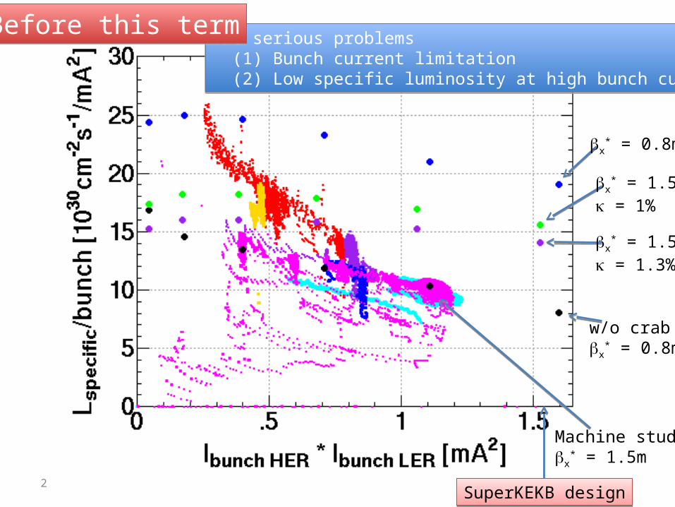
x* = 0.8m
x* = 1.5m
= 1%
x* = 1.5m
= 1.3%
w/o crabx
* = 0.8m
Machine studyx
* = 1.5m
SuperKEKB designSuperKEKB design
Two serious problems (1) Bunch current limitation (2) Low specific luminosity at high bunch currents
Two serious problems (1) Bunch current limitation (2) Low specific luminosity at high bunch currents
Before this termBefore this term
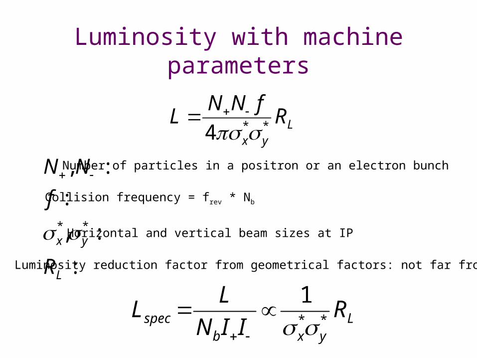
Luminosity with machine parameters
LNN f
4 x* y
*RL
N,N :
f :
x*, y
* :
RL :
Number of particles in a positron or an electron bunch
Collision frequency = frev * Nb
Horizontal and vertical beam sizes at IP
Luminosity reduction factor from geometrical factors: not far from 1
Lspec L
NbII
1
x* y
* RL
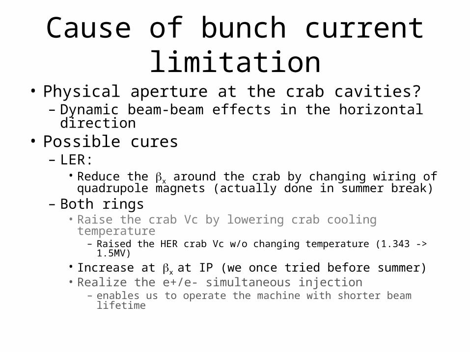
Cause of bunch current limitation• Physical aperture at the crab cavities?
– Dynamic beam-beam effects in the horizontal direction
• Possible cures– LER:
• Reduce the x around the crab by changing wiring of quadrupole magnets (actually done in summer break)
– Both rings• Raise the crab Vc by lowering crab cooling temperature
– Raised the HER crab Vc w/o changing temperature (1.343 -> 1.5MV)• Increase at x at IP (we once tried before summer)• Realize the e+/e- simultaneous injection
– enables us to operate the machine with shorter beam lifetime

Beta’s at LERcrab cavity
(w/o beam-beam)
this fallx
*=0.9mthis fallx
*=0.9mthis fallx
*=1.5mthis fallx
*=1.5m
crab
crab
before summerx
*=0.9mbefore summerx
*=0.9m
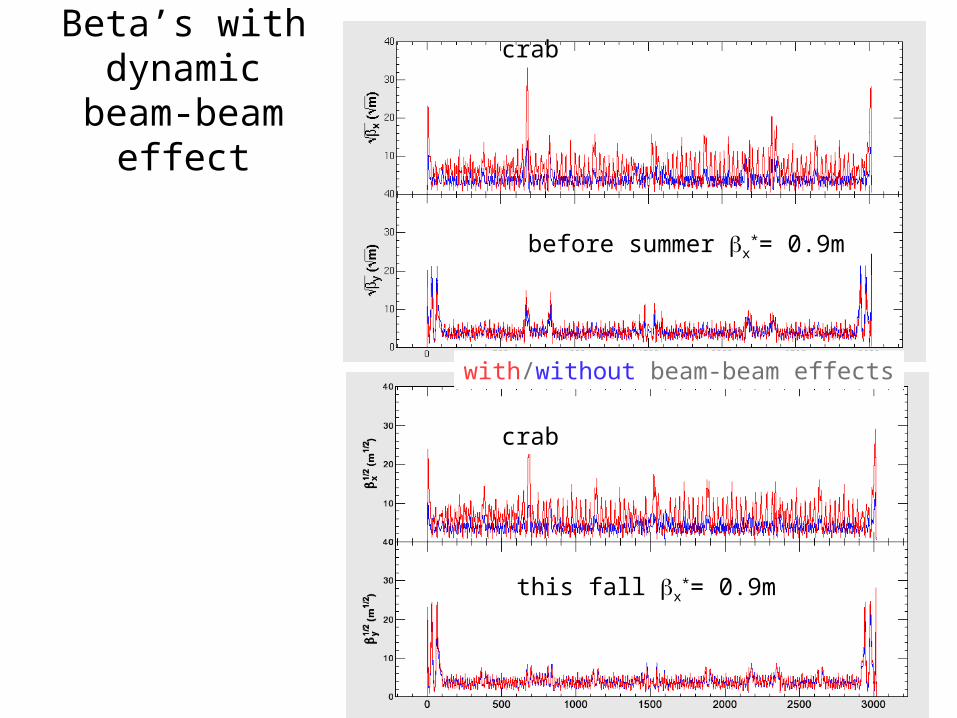
Beta’s with dynamic beam-
beam effect
before summer x*= 0.9m
this fall x*= 0.9m
crab
crab
with/without beam-beam effects
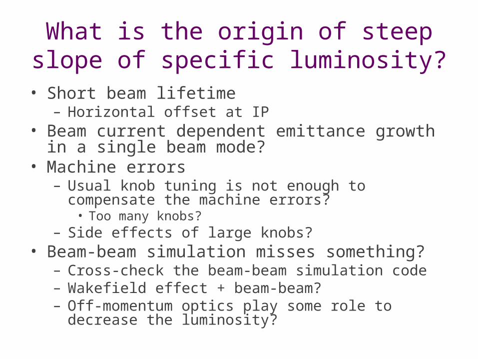
What is the origin of steep slope of specific luminosity?
• Short beam lifetime– Horizontal offset at IP
• Beam current dependent emittance growth in a single beam mode?
• Machine errors– Usual knob tuning is not enough to compensate the
machine errors?• Too many knobs?
– Side effects of large knobs?• Beam-beam simulation misses something?
– Cross-check the beam-beam simulation code– Wakefield effect + beam-beam?– Off-momentum optics play some role to decrease
the luminosity?
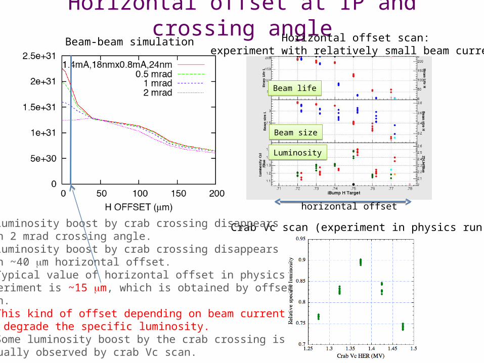
Horizontal offset at IP and crossing angle
Beam lifeBeam life
Beam sizeBeam size
LuminosityLuminosity
Beam-beam simulation Horizontal offset scan:experiment with relatively small beam current
horizontal offset
Crab Vc scan (experiment in physics run) Luminosity boost by crab crossing disappearswith 2 mrad crossing angle. Luminosity boost by crab crossing disappearswith ~40 m horizontal offset. Typical value of horizontal offset in physics experiment is ~15 m, which is obtained by offsetscan. This kind of offset depending on beam currentcan degrade the specific luminosity. Some luminosity boost by the crab crossing isactually observed by crab Vc scan.
Lifetime issue• Can we store more bunch currents and increase the
luminosity by enlarging physical aperture around the crab cavities?
• x*=0.9m
– The LER beam lifetime seems to be longer than before summer.
– The HER beam lifetime is short and the beam loss monitor near crab responds to the HER beam life.
– At nominal operation currents, both LER and HER beam lifetime become short depending on IP horizontal offset.
• We decided to go to x*=1.5m.
– Trial of larger y*
• y*=5.9mm -> 7mm: No significant difference was observed.
Lifetime issue [cont’d]• x
*=1.5m– We could successfully store the high bunch currents
corresponding to the SuperKEKB design.– At I+ x I- ~1.1mA2, no beam lifetime decrease was observed.
However, the achieved luminosity was much lower than the simulation (<- beam size problem).
– At I+ x I- ~1.5mA2, beam lifetime decrease in HER was observed depending on IP horizontal offset. This short lifetime seems to restrict the luminosity somewhat. An aperture survey showed that the physical aperture around the crab is responsible to the short beam lifetime.
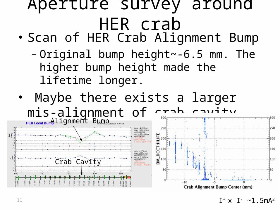
Aperture survey around HER crab• Scan of HER Crab Alignment Bump
– Original bump height~-6.5 mm. The higher bump height made the lifetime longer.
• Maybe there exists a larger mis-alignment of crab cavity.
11
Crab Cavity
Alignment Bump
I+ x I- ~1.5mA2

Horizontal offset target scan
12
Original crab bumpCould not go to the right direction.
Crab bump -5mm in addition to original crab bump
Physical aperture around the crab is responsible to the short beam lifetime and restricted the luminosity.Physical aperture around the crab is responsible to the short beam lifetime and restricted the luminosity.
I+ x I- ~1.5mA2
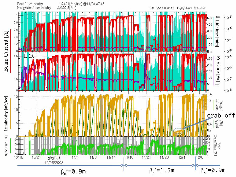
x*=0.9m x
*=1.5m x*=0.9m
crab off
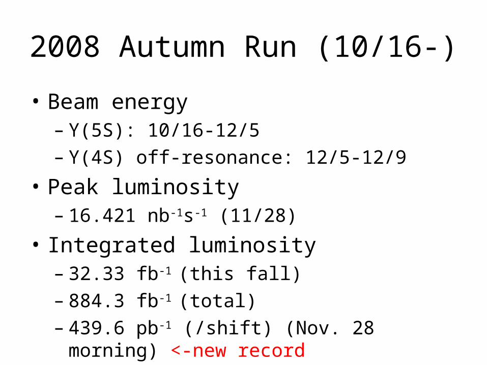
2008 Autumn Run (10/16-)
• Beam energy– Y(5S): 10/16-12/5– Y(4S) off-resonance: 12/5-12/9
• Peak luminosity– 16.421 nb-1s-1 (11/28)
• Integrated luminosity– 32.33 fb-1 (this fall)– 884.3 fb-1 (total)– 439.6 pb-1 (/shift) (Nov. 28 morning) <-new record
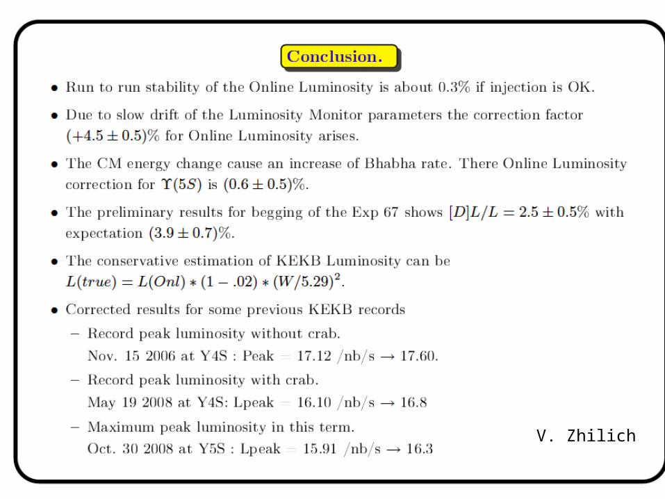
V. Zhilich
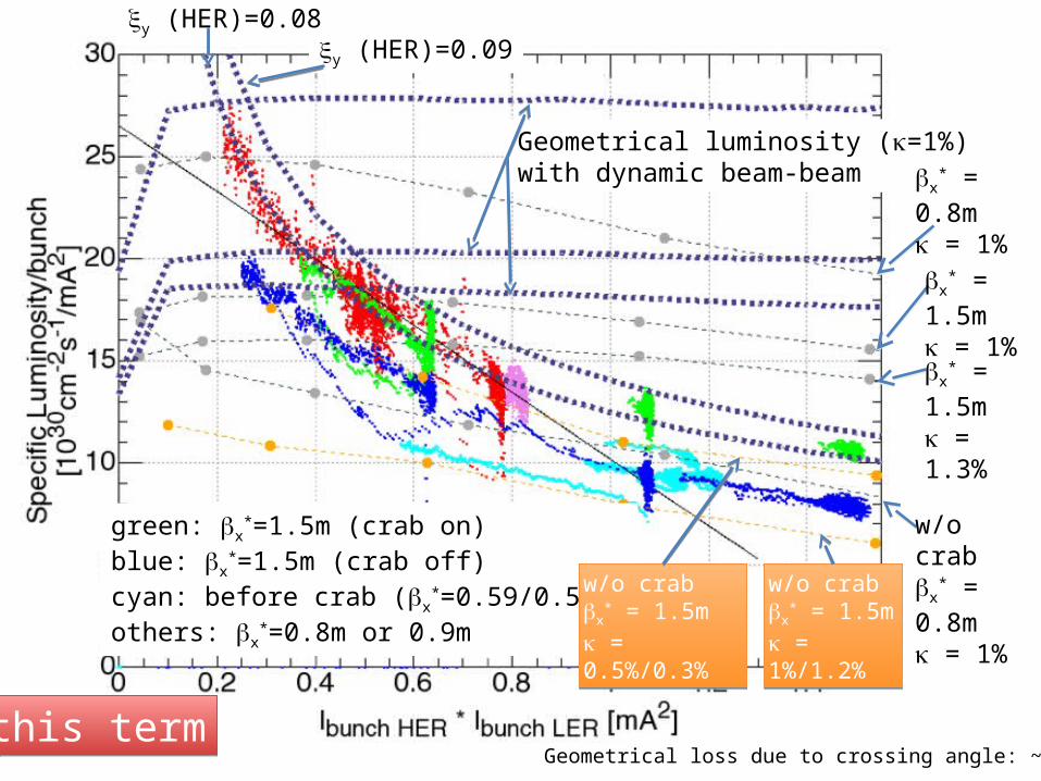
y (HER)=0.09y (HER)=0.08
green: x*=1.5m (crab on)
blue: x*=1.5m (crab off)
cyan: before crab (x*=0.59/0.56m)
others: x*=0.8m or 0.9m
Geometrical luminosity (=1%)with dynamic beam-beam x
* = 0.8m = 1%
x* = 1.5m
= 1%
x* = 1.5m
= 1.3%
w/o crabx
* = 0.8m = 1%w/o crab
x* = 1.5m
= 0.5%/0.3%
w/o crabx
* = 1.5m = 0.5%/0.3%
w/o crabx
* = 1.5m = 1%/1.2%
w/o crabx
* = 1.5m = 1%/1.2%
this termthis termGeometrical loss due to crossing angle: ~11%
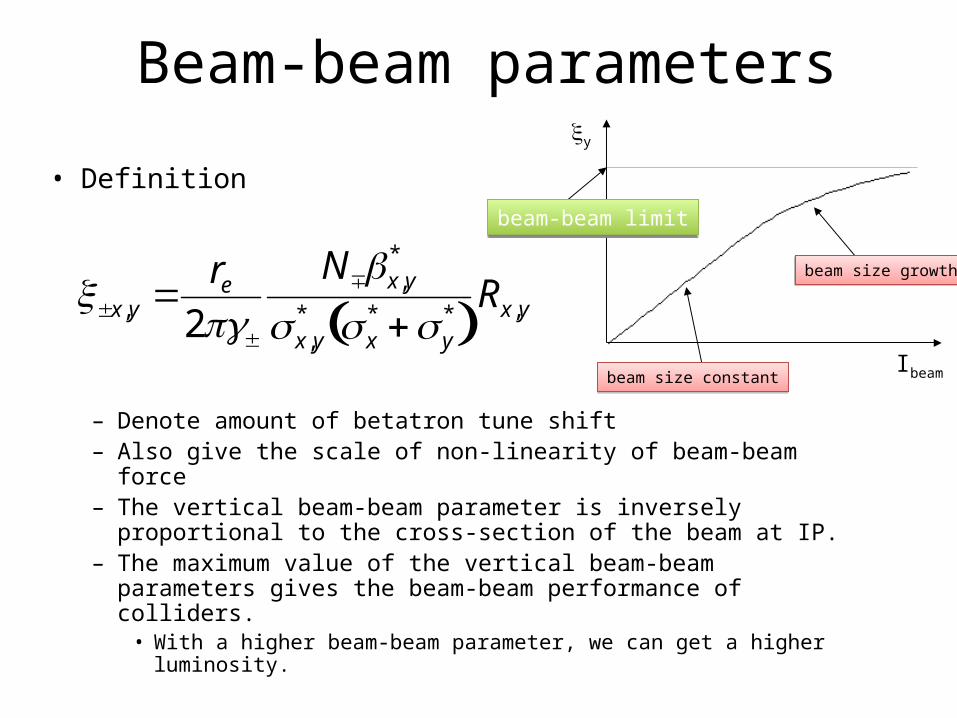
• Definition
– Denote amount of betatron tune shift– Also give the scale of non-linearity of beam-beam force– The vertical beam-beam parameter is inversely proportional to
the cross-section of the beam at IP.– The maximum value of the vertical beam-beam parameters gives
the beam-beam performance of colliders.• With a higher beam-beam parameter, we can get a higher
luminosity.
Beam-beam parameters
x,y re2
Nx,y*
x,y* x
* y* Rx,y
y
Ibeam
beam-beam limitbeam-beam limit
beam size constantbeam size constant
beam size growthbeam size growth
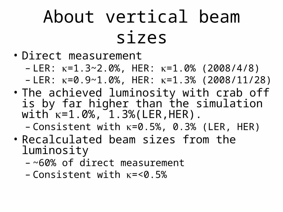
About vertical beam sizes
• Direct measurement– LER: =1.3~2.0%, HER: =1.0% (2008/4/8)– LER: =0.9~1.0%, HER: =1.3% (2008/11/28)
• The achieved luminosity with crab off is by far higher than the simulation with =1.0%, 1.3%(LER,HER).– Consistent with =0.5%, 0.3% (LER, HER)
• Recalculated beam sizes from the luminosity– ~60% of direct measurement– Consistent with =<0.5%
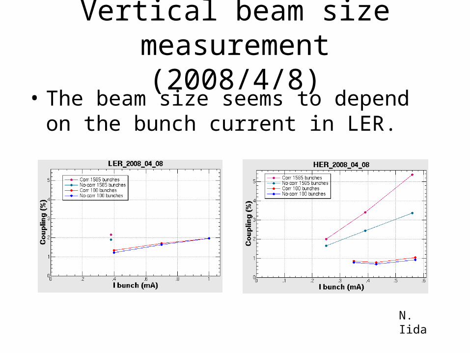
Vertical beam size measurement(2008/4/8)
• The beam size seems to depend on the bunch current in LER.
N. Iida
20
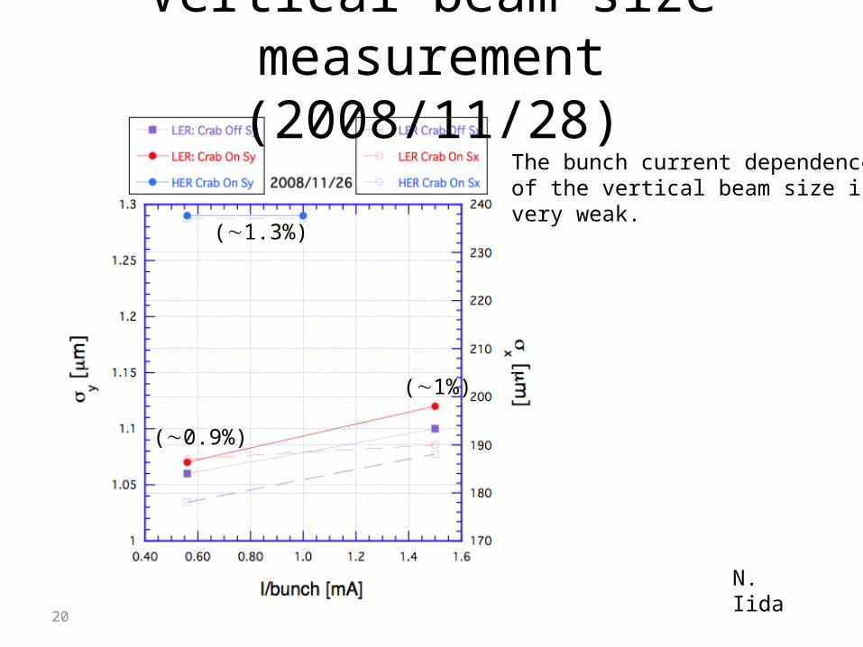
Vertical beam size measurement(2008/11/28)
N. Iida
(∼1%)
(∼0.9%)
(∼1.3%)
The bunch current dependenceof the vertical beam size isvery weak.
Beam-beam simulations• Cross-check the beam-beam simulation code
– We invited Prof. Yunhai Cai from SLAC who is the head of beam physics department.
– He made a beam-beam simulation with a different code from Ohmi-san’s. The result was perfectly consistent with Ohmi-san’s.
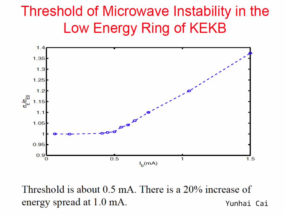
• Prof. Cai is studying the wake field effect on the beam-beam performance. A preliminary result shows no significant effect.– As a byproduct of the study, he showed a possibility that the
microwave instability already occurs in the present LER.
• Ohmi-san and his student (Seimiya-san) are studying effects of momentum dependent optics difference. A preliminary result shows that this difference brings no big effect .
• Tawada-san simulated the knob tuning method in the computer by using Ohmi-san’s code. The result is very interesting.
Yunhai Cai
Beam-beam simulations to investigate effectiveness of method of knob tuning
• Computer simulations have been done on knob tuning (Downhill Simplex Method plus Manual Scan).
• Start with 4 or 5 units of machine errors on 12 coupling and dispersion parameters at IP, with which the luminosity was about 35% of that w/o the errors.
• With the Downhill Simplex method in the computer, the luminosity we achieved was only around 60% of that w/o the errors.
• We could not increase the luminosity with the manual scan after this.
• We tried with another set of initial errors having a similar size. But the resultant luminosity was almost the same.
• These simulations indicate a possibility that we can not reach as the high luminosity as the beam-beam simulation predicts with the usual tuning methods, if the machine errors have some sizes.
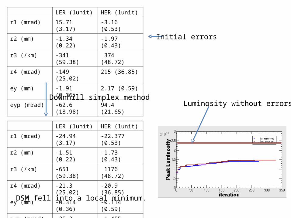
LER (1unit) HER (1unit)
r1 (mrad) 15.71 (3.17) -3.16 (0.53)
r2 (mm) -1.34 (0.22) -1.97 (0.43)
r3 (/km) -341 (59.38) 374 (48.72)
r4 (mrad) -149 (25.02) 215 (36.85)
ey (mm) -1.91 (0.36) 2.17 (0.59)
eyp (mrad) -62.6 (18.98) 94.4 (21.65)
LER (1unit) HER (1unit)
r1 (mrad) -24.94 (3.17) -22.377 (0.53)
r2 (mm) -1.51 (0.22) -1.73 (0.43)
r3 (/km) -651 (59.38) 1176 (48.72)
r4 (mrad) -21.3 (25.02) -20.9 (36.85)
ey (mm) -0.314 (0.36) -0.114 (0.59)
eyp (mrad) -25.3 (18.98) -1.455 (21.65)
Downhill simplex method
DSM fell into a local minimum.
Luminosity without errors
Initial errors
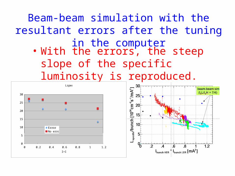
Beam-beam simulation with the resultant errors after the tuning in the computer
• With the errors, the steep slope of the specific luminosity is reproduced.
Lspec
0
5
10
15
20
25
30
0 0.2 0.4 0.6 0.8 1 1.2
I+I-
Lsp
ErrorNo error
Summary (1/3)• We finally confirmed that physical aperture around crab
cavities is responsible for the beam lifetime decrease at high bunch currents (LER, HER).– We will need to fix the misalignment of HER crab cavity.
• This lifetime decrease brings some loss in the luminosity. But its effect on the specific luminosity does not seem as large as initial expectations, although we need further confirmation with x
*=0.9m optics.
• However, we could successfully store the design bunch currents of SuperKEKB.
• This may make some room to increase the luminosity by increasing the beam currents particularly in HER.
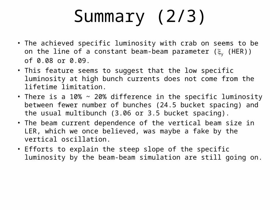
Summary (2/3)• The achieved specific luminosity with crab on seems to be on the
line of a constant beam-beam parameter (y (HER)) of 0.08 or 0.09.
• This feature seems to suggest that the low specific luminosity at high bunch currents does not come from the lifetime limitation.
• There is a 10% ~ 20% difference in the specific luminosity between fewer number of bunches (24.5 bucket spacing) and the usual multibunch (3.06 or 3.5 bucket spacing).
• The beam current dependence of the vertical beam size in LER, which we once believed, was maybe a fake by the vertical oscillation.
• Efforts to explain the steep slope of the specific luminosity by the beam-beam simulation are still going on.

Summary (3/3)
• Some realistic machine errors seem to explain why we can not reach the high luminosity predicted by the beam-beam simulation.
• The luminosity with crab off was unexpectedly high. The difference between crab on and off is about 20%. There is a possibility that the actual vertical beam sizes (w/o beam-beam) are much smaller than the measurements.
• If this is the case, the luminosity predicted by the simulation with crab on becomes much higher than the present one.
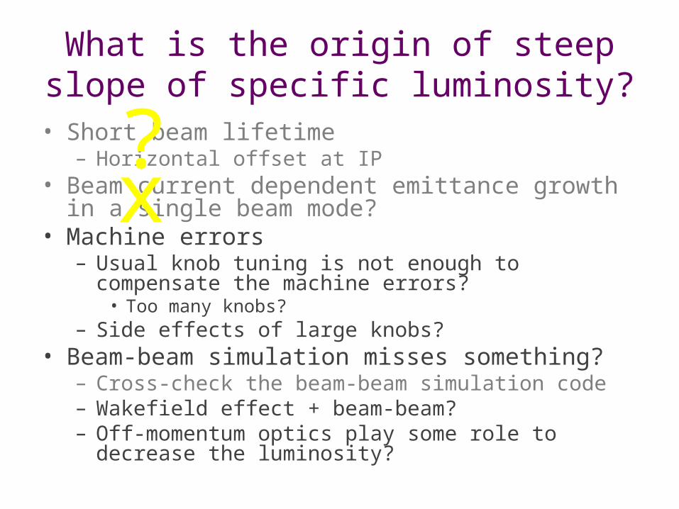
What is the origin of steep slope of specific luminosity?
• Short beam lifetime– Horizontal offset at IP
• Beam current dependent emittance growth in a single beam mode?
• Machine errors– Usual knob tuning is not enough to compensate the
machine errors?• Too many knobs?
– Side effects of large knobs?• Beam-beam simulation misses something?
– Cross-check the beam-beam simulation code– Wakefield effect + beam-beam?– Off-momentum optics play some role to decrease
the luminosity?
x?
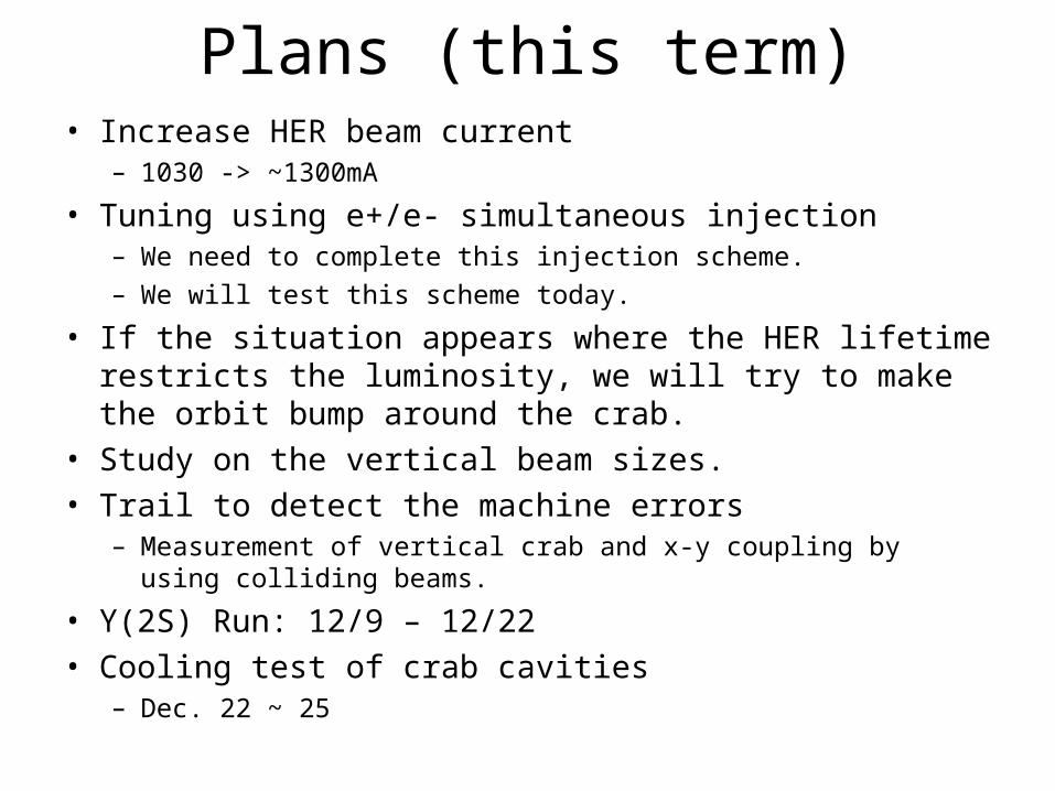
Plans (this term)• Increase HER beam current
– 1030 -> ~1300mA
• Tuning using e+/e- simultaneous injection– We need to complete this injection scheme.– We will test this scheme today.
• If the situation appears where the HER lifetime restricts the luminosity, we will try to make the orbit bump around the crab.
• Study on the vertical beam sizes.• Trail to detect the machine errors
– Measurement of vertical crab and x-y coupling by using colliding beams.
• Y(2S) Run: 12/9 – 12/22• Cooling test of crab cavities
– Dec. 22 ~ 25
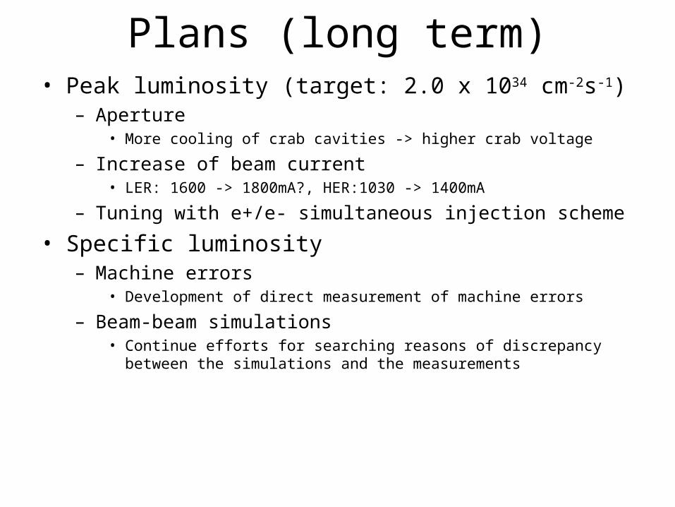
Plans (long term)• Peak luminosity (target: 2.0 x 1034 cm-2s-1)
– Aperture• More cooling of crab cavities -> higher crab voltage
– Increase of beam current• LER: 1600 -> 1800mA?, HER:1030 -> 1400mA
– Tuning with e+/e- simultaneous injection scheme
• Specific luminosity– Machine errors
• Development of direct measurement of machine errors
– Beam-beam simulations• Continue efforts for searching reasons of discrepancy between the simulations and
the measurements
32
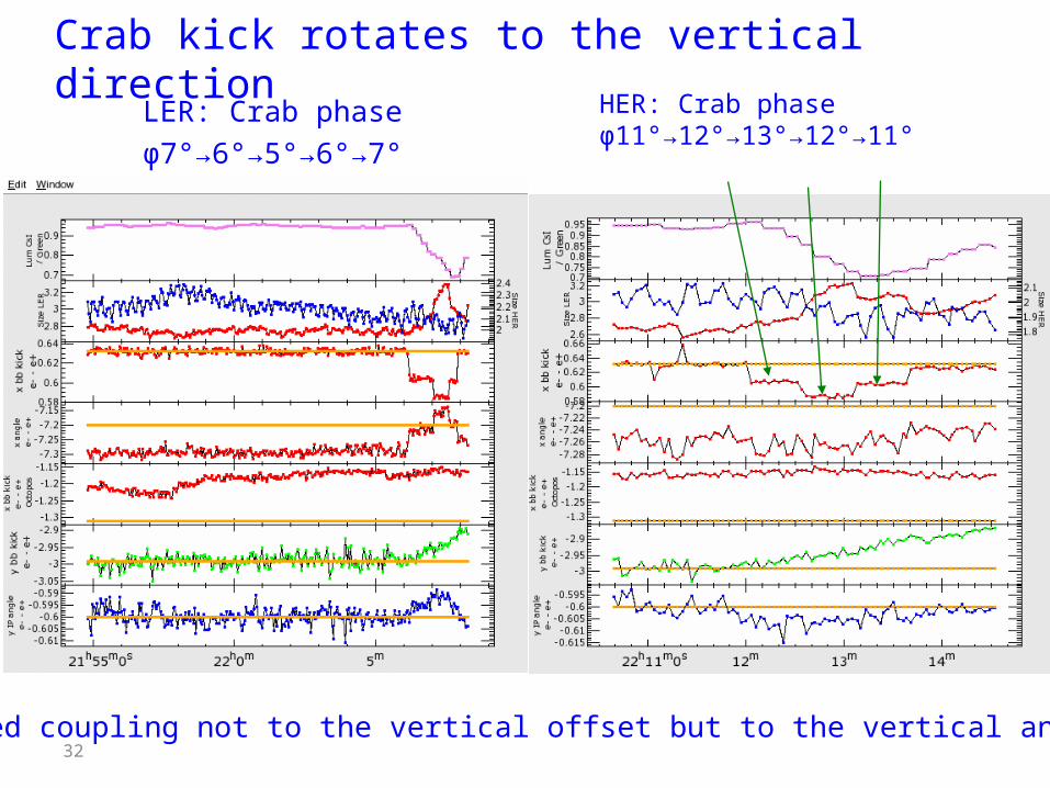
Crab kick rotates to the vertical directionLER: Crab phaseφ7°→6°→5°→6°→7°
HER: Crab phaseφ11°→12°→13°→12°→11°
We observed coupling not to the vertical offset but to the vertical angle at IP.
Spare slides
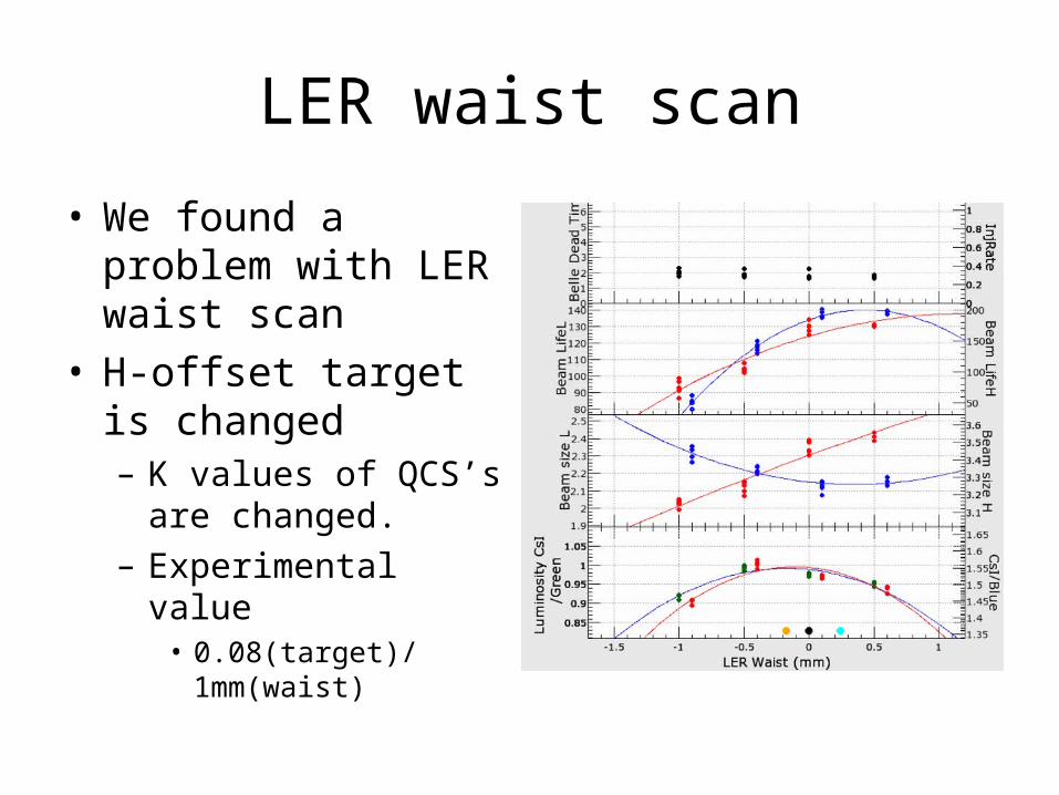
LER waist scan
• We found a problem with LER waist scan
• H-offset target is changed– K values of QCS’s are
changed.– Experimental value
• 0.08(target)/1mm(waist)
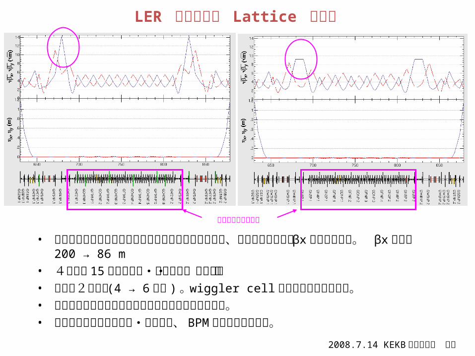
LER 日光直線部 Lattice 変更案
• 衝突時のビーム寿命を制限している可能性があるので、クラブ空洞上流の βxを小さくする。 βx最大値 200 → 86 m
• 4極磁石 15台分を転極・結線変更・名称変更。• 新電源2台追加 (4 → 6電源 ) 。wiggler cellの端を独立電源にする。• 日光直線部のベータトロン位相を現在と同じに保てる。• ステアリングの配置変更・名称変更、 BPMの名称変更も必要。
2008.7.14 KEKB打ち合わせ 小磯
この部分を変更する
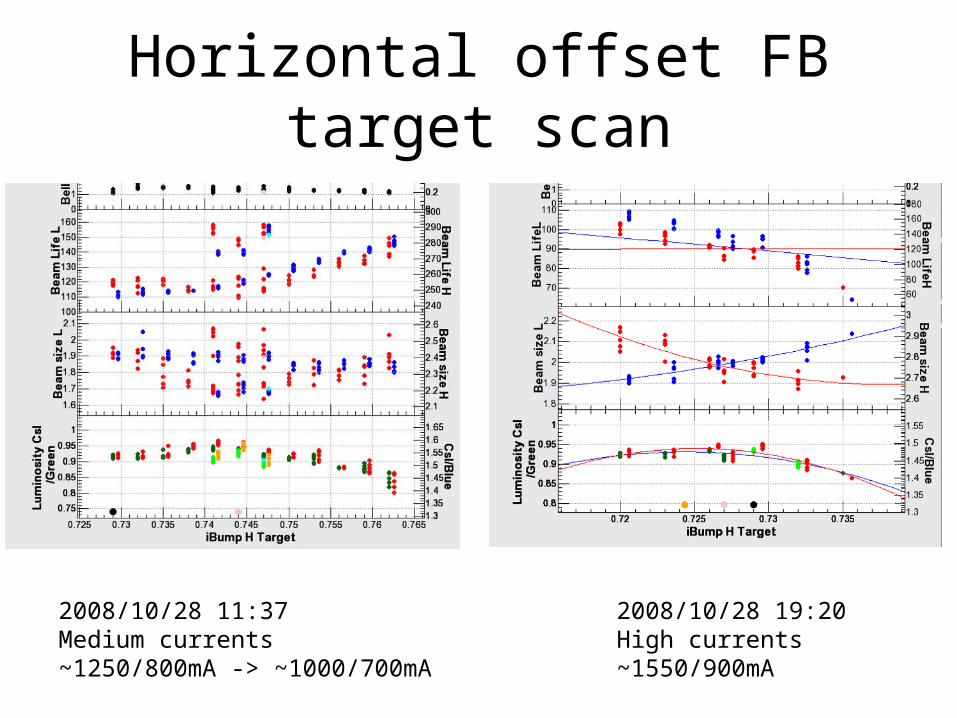
Horizontal offset FB target scan
2008/10/28 19:20High currents~1550/900mA
2008/10/28 11:37Medium currents~1250/800mA -> ~1000/700mA