kenneth pedersen 3.2.3 wave power for the western cape · wave power for the western cape kenneth...
TRANSCRIPT
Wave Powerfor the
Western Cape
Kenneth Pedersen
PRESTEDGE RETIEF DRESNER WIJNBERG (PTY) LTD
Presentation Outline
• Introduction
• SWEC– Original Development– Viability for Western Cape– Future Development
Introduction
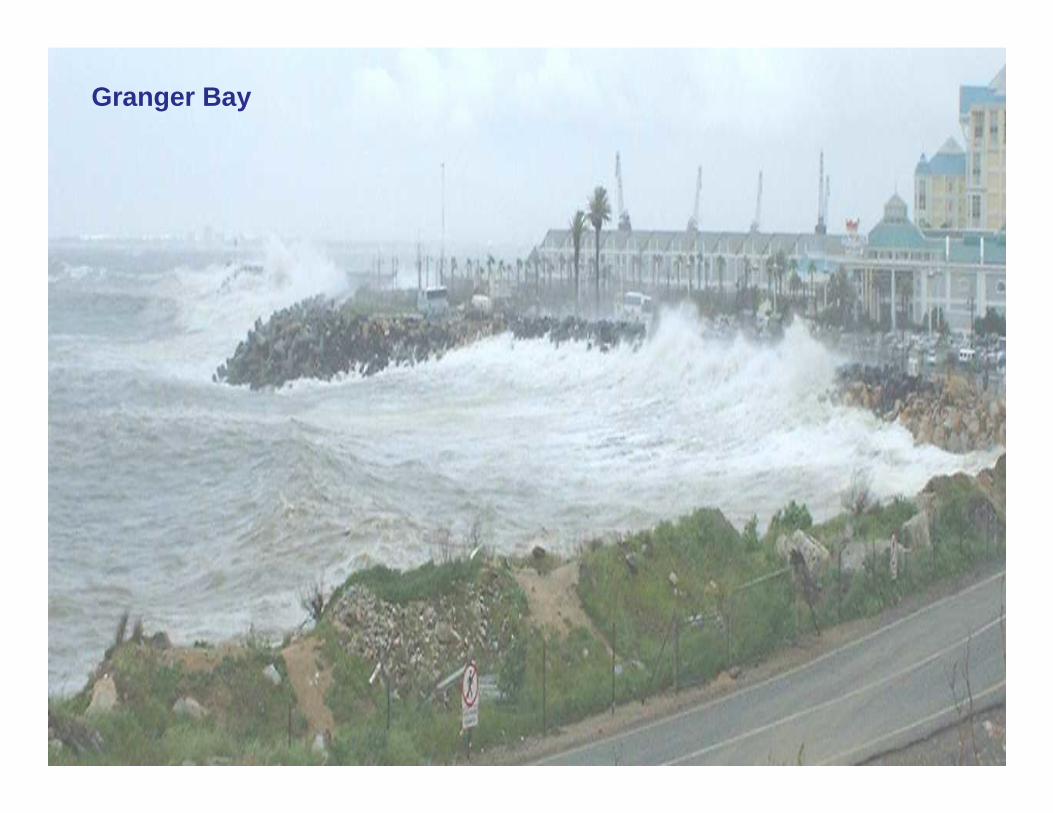
Granger Bay
Lamberts Bay
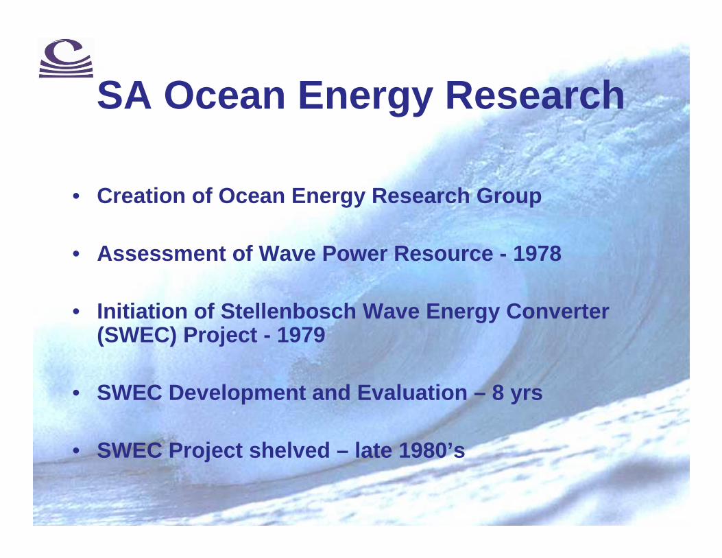
SA Ocean Energy Research
• Creation of Ocean Energy Research Group
• Assessment of Wave Power Resource - 1978
• Initiation of Stellenbosch Wave Energy Converter (SWEC) Project - 1979
• SWEC Development and Evaluation – 8 yrs
• SWEC Project shelved – late 1980’s

Wave Power Levels – SA
20
30
45 13
12
Units: kW/m crest lengthPredominant Wave Direction
25
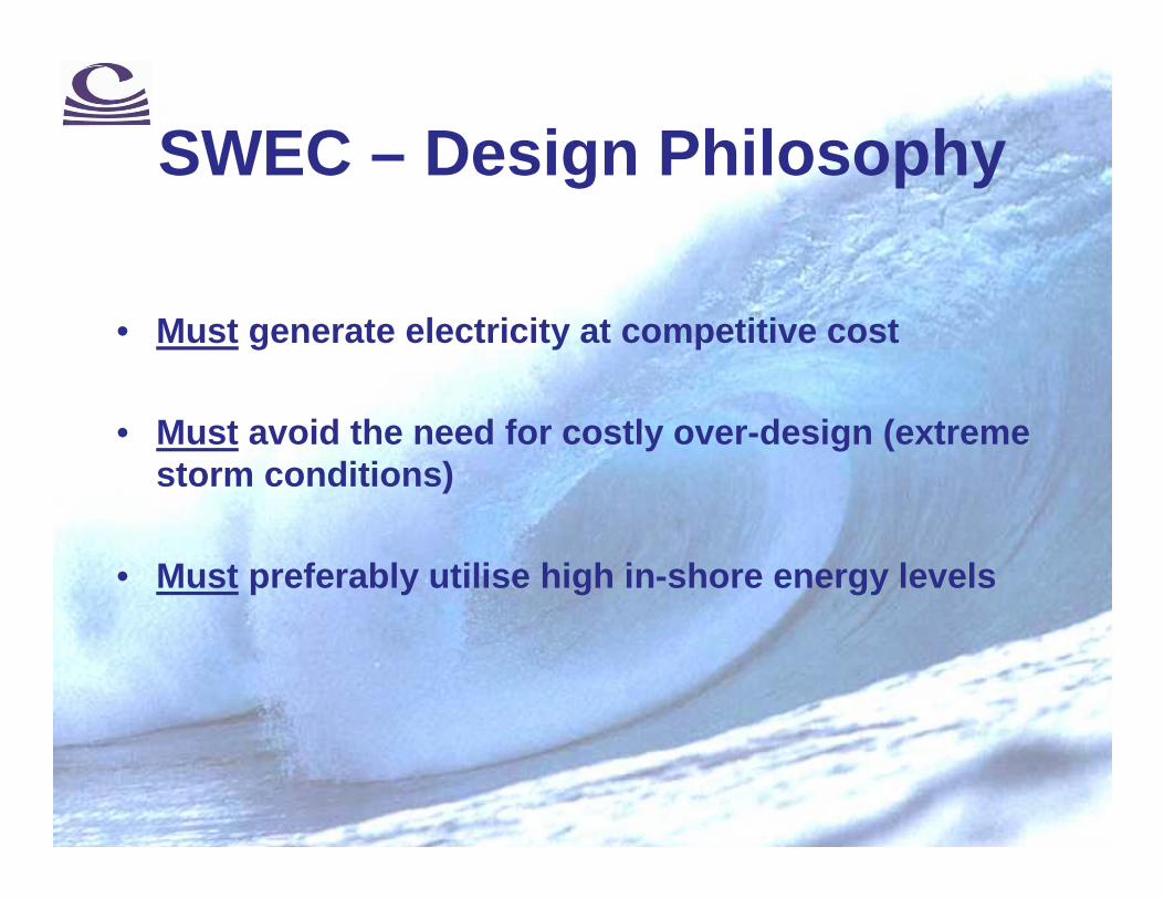
SWEC – Design Philosophy
• Must generate electricity at competitive cost
• Must avoid the need for costly over-design (extreme storm conditions)
• Must preferably utilise high in-shore energy levels

SWEC – Design Philosophy
• Must not interfere with shipping routes and fishing industry
• Must be within local technological capability
• Must have minimum visual and environmental impact
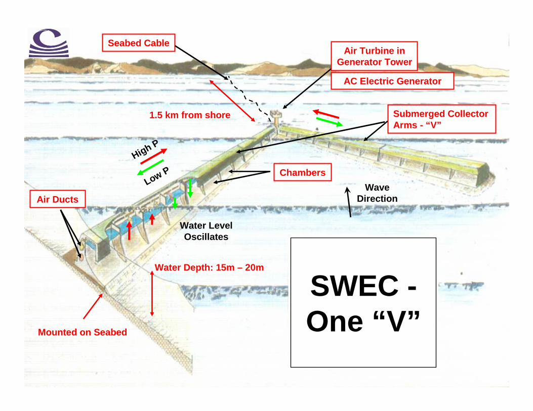
SWEC -One “V”
Air Ducts
Chambers
Submerged CollectorArms - “V”
WaveDirection
Mounted on Seabed
Water Depth: 15m – 20m
1.5 km from shore
Water LevelOscillates
High P
Low P
AC Electric Generator
Seabed CableAir Turbine in
Generator Tower

Wave Crest
High Pressure Phase
TrappedAir Pocket
High PressureAir Duct
SWEC - Concept

Wave Trough
Low Pressure Phase
TrappedAir Pocket
Low PressureAir Duct
SWEC - Concept

-
Model Studies – 2D

-
Model Studies – 2D

-
Model Studies – 3D
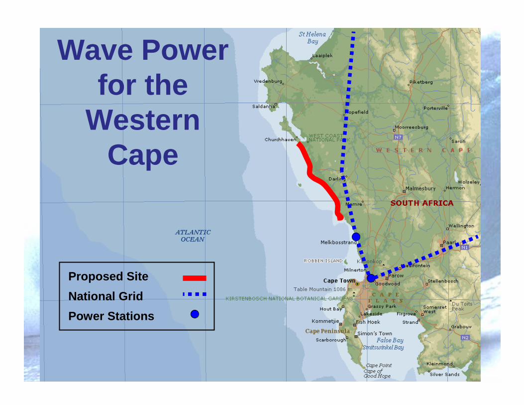
Proposed Site
National Grid
Power Stations
Wave Powerfor the
Western Cape

SWEC -Array Collector
Substation
Sea
bed
Cab
le
Shore Line
National Grid15
00m
Wave Direction
SWEC “V” Units
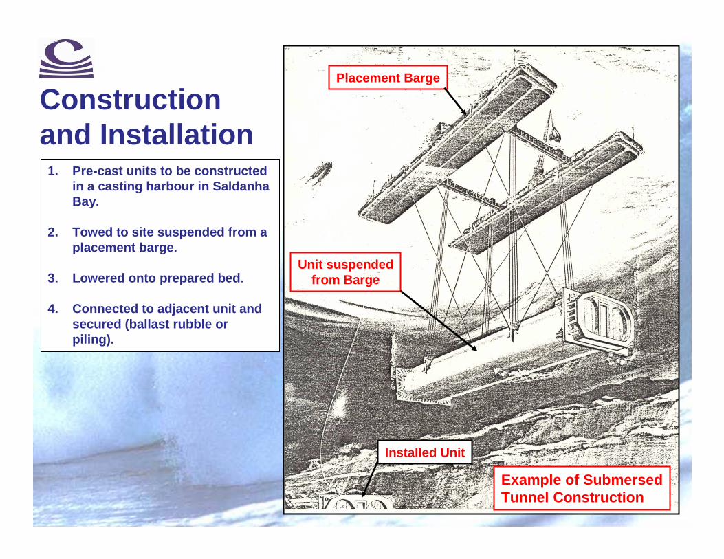
Constructionand Installation
1. Pre-cast units to be constructed in a casting harbour in Saldanha Bay.
2. Towed to site suspended from a placement barge.
3. Lowered onto prepared bed.
4. Connected to adjacent unit and secured (ballast rubble or piling).
Placement Barge
Example of SubmersedTunnel Construction
Installed Unit
Unit suspendedfrom Barge

SWEC – Power Generation
One “V”Total
(40 km)
Rated (Design) Capacity
5 MW 770 MW
Annual Average
2 MW 308 MW
Winter Average
2.9 MW 450 MW
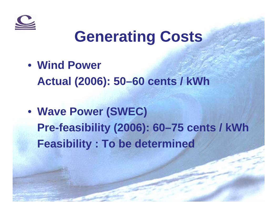
Generating Costs
• Wind PowerActual (2006): 50–60 cents / kWh
• Wave Power (SWEC)Pre-feasibility (2006): 60–75 cents / kWhFeasibility : To be determined

SWEC – Future Development• Phase 1: Feasibility Study
• Phase 2: Detail Design (5 MW Demo Unit)
• Phase 3: Implementation (5 MW Demo Unit)
• Phase 4: Testing (5 MW Demo Unit)
• Phase 5: Implementation (770 MW)
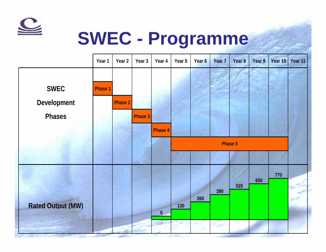
SWEC - ProgrammeYear 1 Year 2 Year 3 Year 4 Year 5 Year 6 Year 7 Year 8 Yea r 9 Year 10 Year 11
SWEC Phase 1
Development Phase 2
Phases Phase 3
Phase 4
770650
520390
260
Rated Output (MW) 1305
Phase 5

Wave Energy for the Western Cape
Discussion
PRESTEDGE RETIEF DRESNER WIJNBERG (PTY) LTD