kes enviro redivent - spring air systems · 2015-10-13 · 1 kes enviro redivent installation,...
TRANSCRIPT
1
KES Enviro Redivent Installation, Operating and
Maintenance Manual
July 2015 Spring Air Systems Inc.
Phone (905) 338-2999, Fax (905) 338-0179, [email protected] www.springairsystems.com
KES Enviro Redivent 2015 2
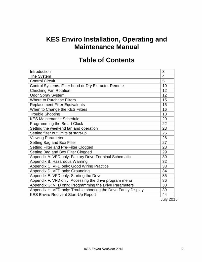
KES Enviro Installation, Operating and Maintenance Manual
Table of Contents
Introduction 3
The System 4
Control Circuit 5
Control Systems: Filter hood or Dry Extractor Remote 10
Checking Fan Rotation 12
Odor Spray System 12
Where to Purchase Filters 15
Replacement Filter Equivalents 15
When to Change the KES Filters 16
Trouble Shooting 18
KES Maintenance Schedule 20
Programming the Smart Clock 22
Setting the weekend fan and operation 23
Setting filter out limits at start-up 25
Viewing Parameters 26
Setting Bag and Box Filter 27
Setting Filter and Pre-Filter Clogged 28
Setting Bag and Box Filter Clogged 29
Appendix A: VFD only: Factory Drive Terminal Schematic 30
Appendix B: Hazardous Warning 32
Appendix C: VFD only: Good Wiring Practice 33
Appendix D: VFD only: Grounding 34
Appendix E: VFD only: Starting the Drive 35
Appendix F: VFD only: Accessing the drive program menu 36
Appendix G: VFD only: Programming the Drive Parameters 38
Appendix H: VFD only: Trouble shooting the Drive Faulty Display 39
KES Enviro Redivent Start-Up Report 44
July 2015
KES Enviro Redivent 2015 3
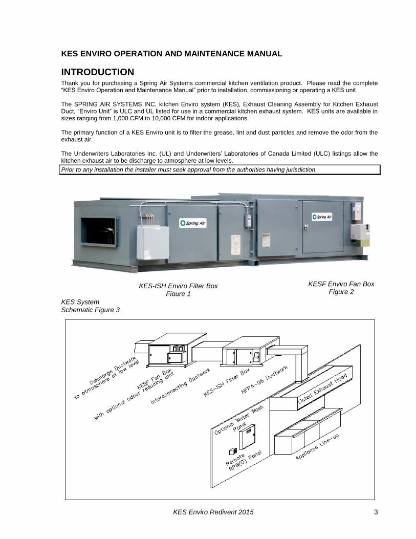
KES ENVIRO OPERATION AND MAINTENANCE MANUAL
INTRODUCTION Thank you for purchasing a Spring Air Systems commercial kitchen ventilation product. Please read the complete “KES Enviro Operation and Maintenance Manual” prior to installation, commissioning or operating a KES unit. The SPRING AIR SYSTEMS INC. kitchen Enviro system (KES), Exhaust Cleaning Assembly for Kitchen Exhaust Duct, “Enviro Unit” is ULC and UL listed for use in a commercial kitchen exhaust system. KES units are available in sizes ranging from 1,000 CFM to 10,000 CFM for indoor applications. The primary function of a KES Enviro unit is to filter the grease, lint and dust particles and remove the odor from the exhaust air. The Underwriters Laboratories Inc. (UL) and Underwriters’ Laboratories of Canada Limited (ULC) listings allow the kitchen exhaust air to be discharge to atmosphere at low levels.
Prior to any installation the installer must seek approval from the authorities having jurisdiction.
KES System Schematic Figure 3
KES-ISH Enviro Filter Box Figure 1
KESF Enviro Fan Box Figure 2
KES Enviro Redivent 2015 4
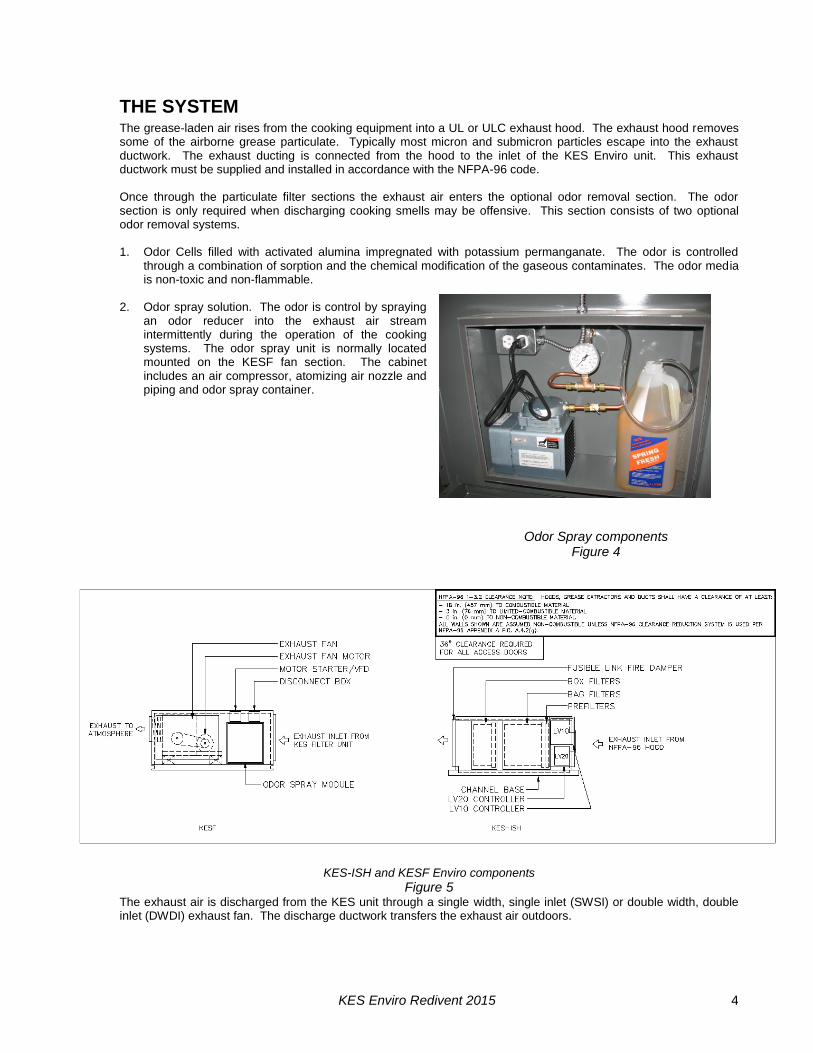
THE SYSTEM The grease-laden air rises from the cooking equipment into a UL or ULC exhaust hood. The exhaust hood removes some of the airborne grease particulate. Typically most micron and submicron particles escape into the exhaust ductwork. The exhaust ducting is connected from the hood to the inlet of the KES Enviro unit. This exhaust ductwork must be supplied and installed in accordance with the NFPA-96 code. Once through the particulate filter sections the exhaust air enters the optional odor removal section. The odor section is only required when discharging cooking smells may be offensive. This section consists of two optional odor removal systems. 1. Odor Cells filled with activated alumina impregnated with potassium permanganate. The odor is controlled
through a combination of sorption and the chemical modification of the gaseous contaminates. The odor media is non-toxic and non-flammable.
2. Odor spray solution. The odor is control by spraying
an odor reducer into the exhaust air stream intermittently during the operation of the cooking systems. The odor spray unit is normally located mounted on the KESF fan section. The cabinet includes an air compressor, atomizing air nozzle and piping and odor spray container.
KES-ISH and KESF Enviro components
Figure 5 The exhaust air is discharged from the KES unit through a single width, single inlet (SWSI) or double width, double inlet (DWDI) exhaust fan. The discharge ductwork transfers the exhaust air outdoors.
Odor Spray components Figure 4

KES Enviro Redivent 2015 5
CONTROL CIRCUIT
Filter Clogged:
During normal operation of the KES unit three-filter stages collect grease, dust, and lint particulate. The type of cooking equipment and the hours of operation determines the useful life of the individual filters.
Pressure Switch Locations Figure 6
Box Filter probes as viewed from discharge
Figure 7
KES Enviro Redivent 2015 6
Typical indoor KES, motor starter, LV10 J-Box with odor spray wiring schematic Figure 8
Pressure transducers have been installed to determine when the filters are totally used and must be replaced. As the filter reaches the grease loading capacity the static pressure across each filter increases. When the maximum static pressure is reached the pressure alarm is activated. The exhaust fan shuts off, the “NORMAL” pilot energizes, and the kitchen remote panel annunciates a filter-clogged condition. (The remote panel indicates which stage of filters has clogged; PREFILTER, BAG FILTER, or BOX FILTER.) In addition the screen of the LOGO controller in the RPD10 or RPW10 has a text message also indicating which filter is clogged.
AUX!
PrefilterChange
AUX!ChangeBag Filter
AUX!
Box FilterChange
SMART SMART
SMART
RPD10 or RPW10 LOGO controller indicating Box Filter clogged text messages
Figure 9
KES Enviro Redivent 2015 7
The clogged filter must be replaced and the system reset to resume normal operation. If this condition occurs during normally operating hours rotate the OVERRIDE selector switch and the fan will come back on. The systems can run in the OVERRIDE position for about 4 hours. (See the section the OVERRIDE switch) If the system runs longer than 4 hours the fan will shut down. The filters must be changed and the system reset. It is recommended that the filters be changed prior to the filter clogged light energizing. A filter usage chart is attached to record when the filters are being changed. Using this chart a regular maintenance schedule can be set up to ensure constant uninterrupted operation of the commercial kitchen.
Filter Removed: Should the bag or box filters be removed during normal operation the KES unit is automatically shut down. A pressure transducer across the bag filters and box filters monitors a minimum pressure drop of 0.25” W.C. When the filter is removed the pressure differential falls and the pressure switch is activated. The exhaust fan shuts off, the “FILTER REMOVED” pilot light on the RPD10 or RPW10 energizes and the screen of the LOGO controller in the RPD10 or RPW10 has a text message indicating “FILTER REMOVED/LOW EXHAUST. To resume normal operation the filter must be replaced and the system reset. (See the section the OVERRIDE switch)
AUX!FiltersRemovedor LowExhaust
SMART
RPD10 or RPW10 LOGO controller indicating filter removed text message Figure 10
Fire:
In the event of a high temperature in the ductwork leading to the KES unit or within the KES unit a firestat located at the inlet of the KES filter section is activated. When the exhaust air reaches 160 F the firestat is energized. The exhaust fan shuts off, the “NORMAL” pilot goes off, and a “FIRE” pilot energizes on the remote RPD10 or RPW10 panel. Should the exhaust temperature continue to rise the fusible link melts and closes the fire damper in the exhaust discharge of the KES filter section. This fire damper is always located between the fan and filter section. The fire damper fusible link is rated at 165 F. Shut off all cooking equipment and notify the fire department. To resume normal operation, replace the fusible link and reset the system. An authorized SPRING AIR SYSTEM INC. service technician should be called to inspect the unit.
Override Switch: (located on RPW10 or RPD10 panel)
In the event that the filter clogged annunciation shuts off the KES unit during a peak cooking time rotate the OVERRIDE SWITCH located on the RPW10 panel clockwise. The WARNING pilot light will energize and the FILTER CLOGGED and NORMAL lights will turn off. This is a temporary override to allow for the cooking equipment to be shut off prior to changing the filters. The systems can run in the OVERRIDE position for 4 hours. If the system runs longer than 4 hours the fan will shut down. The filters must be changed and the system reset. It is recommended that the filters be changed prior to the filter clogged light energizing. A filter usage chart is attached to record when the filters are being changed. Using this chart a regular maintenance schedule can be set up to ensure constant uninterrupted operation of the commercial kitchen. Once the dirty filter has been replaced rotate the OVERRIDE SWITCH to counter clock wise to resume normal operation.
KES Enviro Redivent 2015 8
AUX!
4 hours
FiltersService
Within
SMART
RPD10 or RPW10 LOGO with Override selector in on position Figure 11
System Reset:
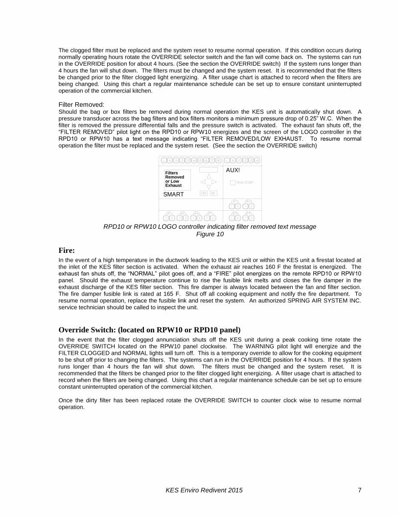
After any of the safety circuit annunciation, the system must be reset. The system is reset by toggling the “RESET” switch in the LV10 J-box, or switching the OVERRIDE SWITCH on the RPW10 or RPD10, or turning the fan selector switch to the “OFF” and then to the “ON” position.
Logo Processor
Figure 12
KES Enviro Redivent 2015 9
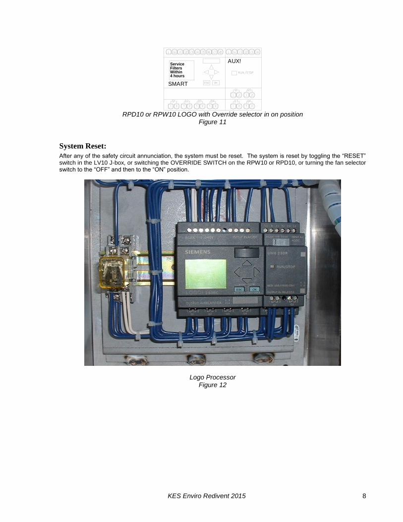
RPD-KD & RPD-KW Face Plate
Figure 13
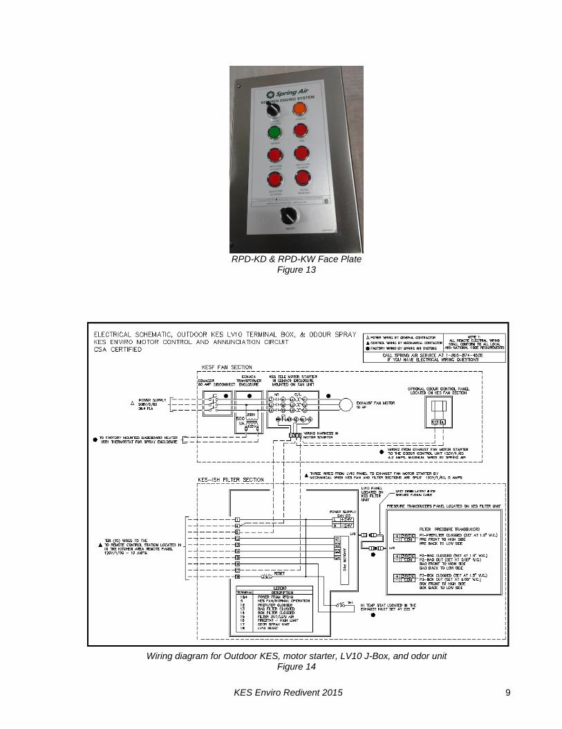
Wiring diagram for Outdoor KES, motor starter, LV10 J-Box, and odor unit Figure 14
KES Enviro Redivent 2015 10
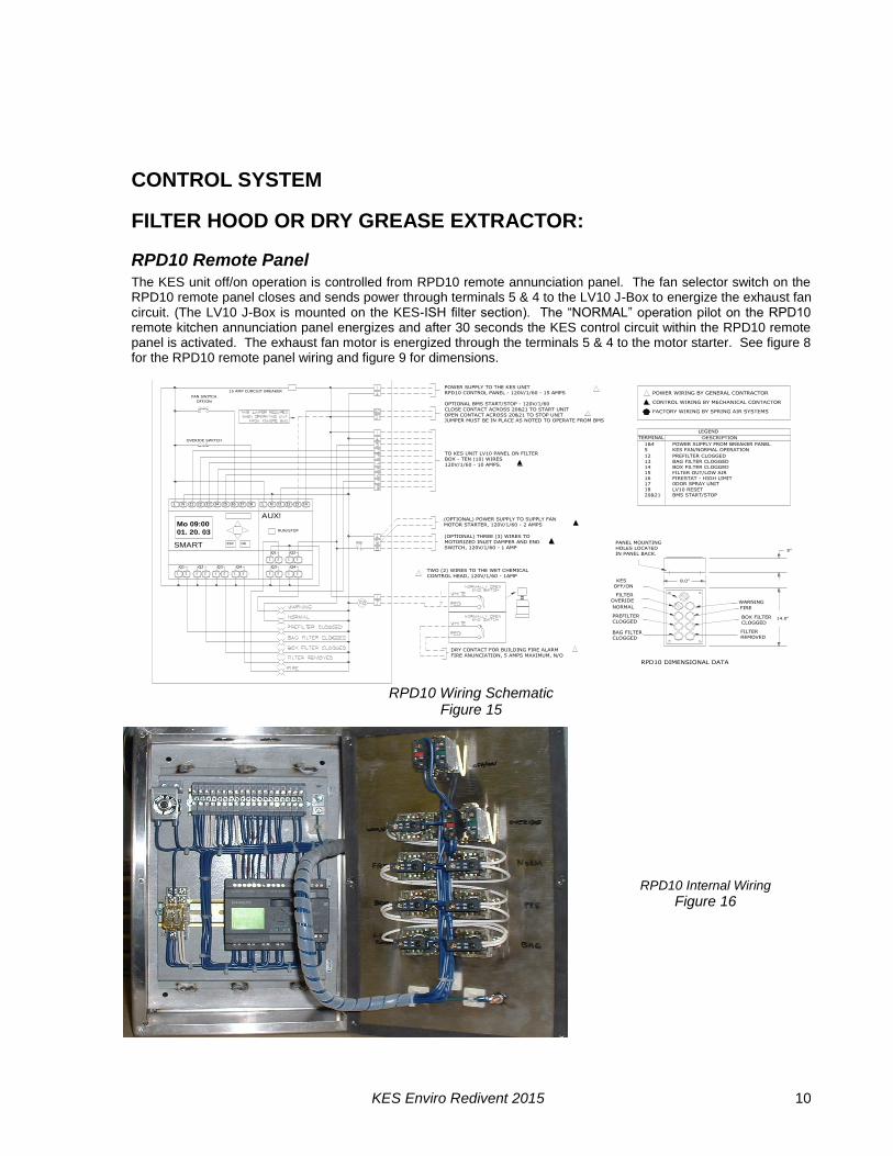
CONTROL SYSTEM
FILTER HOOD OR DRY GREASE EXTRACTOR:
RPD10 Remote Panel
The KES unit off/on operation is controlled from RPD10 remote annunciation panel. The fan selector switch on the RPD10 remote panel closes and sends power through terminals 5 & 4 to the LV10 J-Box to energize the exhaust fan circuit. (The LV10 J-Box is mounted on the KES-ISH filter section). The “NORMAL” operation pilot on the RPD10 remote kitchen annunciation panel energizes and after 30 seconds the KES control circuit within the RPD10 remote panel is activated. The exhaust fan motor is energized through the terminals 5 & 4 to the motor starter. See figure 8 for the RPD10 remote panel wiring and figure 9 for dimensions.
JUMPER MUST BE IN PLACE AS NOTED TO OPERATE FROM BMS
OPTIONAL BMS START/STOP - 120V/1/60
CLOSE CONTACT ACROSS 20&21 TO START UNIT
OPEN CONTACT ACROSS 20&21 TO STOP UNIT
RPD10 CONTROL PANEL - 120V/1/60 - 15 AMPS
TO KES UNIT LV10 PANEL ON FILTER
POWER SUPPLY TO THE KES UNIT
MOTOR STARTER, 120V/1/60 - 2 AMPS
(OPTIONAL) POWER SUPPLY TO SUPPLY FAN
FIRE ANUNCIATION, 5 AMPS MAXIMUM, N/O
DRY CONTACT FOR BUILDING FIRE ALARM
(OPTIONAL) THREE (3) WIRES TO
MOTORIZED INLET DAMPER AND END
SWITCH, 120V/1/60 - 1 AMP
TWO (2) WIRES TO THE WET CHEMICAL
CONTROL HEAD, 120V/1/60 - 1AMP
SMART
2
2
Q3Q1
1 2
Q2
1 2 1 2
Q4
1 2
ESC OK
1
Q3
1
Q1
1 2
Q4
1 2
Q2
15 AMP CURCUIT BREAKER
AUX!
FAN SWITCH
I4I2L N I1 I3
01. 20. 03
Mo 09:00
I5 I6 I7 I8 L N
OVERIDE SWITCH
OFF/ON
RPD10A ELECTRICAL DATA
I1 I2 I3 I4
RUN/STOP
BOX - TEN (10) WIRES
120V/1/60 - 10 AMPS.
PANEL MOUNTING
FILTER
BOX FILTER
CLOGGED
WARNING
REMOVED
FILTER
CLOGGED
PREFILTER
CLOGGED
BAG FILTER
HOLES LOCATED
IN PANEL BACK.
OVERIDE
NORMAL
KES
OFF/ON
RPD10 DIMENSIONAL DATA
8.0"
FIRE
14.0"
5"
POWER SUPPLY FROM BREAKER PANEL
CONTROL WIRING BY MECHANICAL CONTACTOR
FACTORY WIRING BY SPRING AIR SYSTEMS
POWER WIRING BY GENERAL CONTRACTOR
14 BOX FILTER CLOGGED
FIRESTAT - HIGH LIMIT
0DOR SPRAY UNIT
BMS START/STOP
LV10 RESET
FILTER OUT/LOW AIR
18
20&21
17
16
15
PREFILTER CLOGGED
BAG FILTER CLOGGED
KES FAN/NORMAL OPERATION
TERMINAL
5
13
12
1&4
LEGEND
DESCRIPTION
RPD10 Wiring Schematic Figure 15
RPD10 Internal Wiring
Figure 16
KES Enviro Redivent 2015 11
REMOVED
WARNING
CLOGGED
BOX FILTER
FILTER
OVERIDE
BAG FILTER
CLOGGED
PREFILTER
CLOGGED
NORMAL FIRE
IN PANEL BACK.
HOLES LOCATED
PANEL MOUNTING
KES
OFF/ON
FILTER
8.0"
14.0"
5"
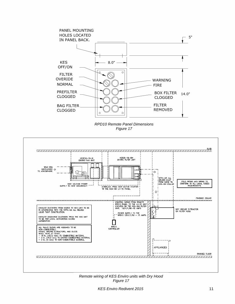
RPD10 Remote Panel Dimensions
Figure 17
Remote wiring of KES Enviro units with Dry Hood Figure 17
KES Enviro Redivent 2015 12
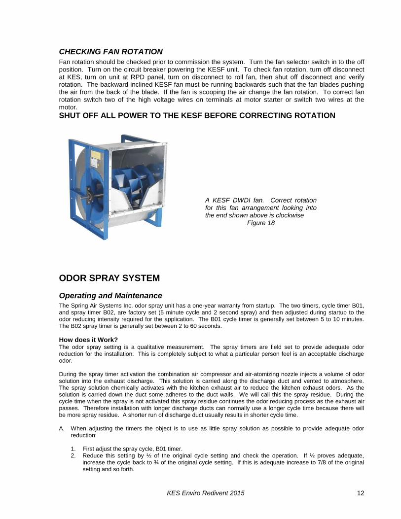
CHECKING FAN ROTATION
Fan rotation should be checked prior to commission the system. Turn the fan selector switch in to the off position. Turn on the circuit breaker powering the KESF unit. To check fan rotation, turn off disconnect at KES, turn on unit at RPD panel, turn on disconnect to roll fan, then shut off disconnect and verify rotation. The backward inclined KESF fan must be running backwards such that the fan blades pushing the air from the back of the blade. If the fan is scooping the air change the fan rotation. To correct fan rotation switch two of the high voltage wires on terminals at motor starter or switch two wires at the motor.
SHUT OFF ALL POWER TO THE KESF BEFORE CORRECTING ROTATION
ODOR SPRAY SYSTEM
Operating and Maintenance
The Spring Air Systems Inc. odor spray unit has a one-year warranty from startup. The two timers, cycle timer B01, and spray timer B02, are factory set (5 minute cycle and 2 second spray) and then adjusted during startup to the odor reducing intensity required for the application. The B01 cycle timer is generally set between 5 to 10 minutes. The B02 spray timer is generally set between 2 to 60 seconds.
How does it Work? The odor spray setting is a qualitative measurement. The spray timers are field set to provide adequate odor reduction for the installation. This is completely subject to what a particular person feel is an acceptable discharge odor. During the spray timer activation the combination air compressor and air-atomizing nozzle injects a volume of odor solution into the exhaust discharge. This solution is carried along the discharge duct and vented to atmosphere. The spray solution chemically activates with the kitchen exhaust air to reduce the kitchen exhaust odors. As the solution is carried down the duct some adheres to the duct walls. We will call this the spray residue. During the cycle time when the spray is not activated this spray residue continues the odor reducing process as the exhaust air passes. Therefore installation with longer discharge ducts can normally use a longer cycle time because there will be more spray residue. A shorter run of discharge duct usually results in shorter cycle time. A. When adjusting the timers the object is to use as little spray solution as possible to provide adequate odor
reduction:
1. First adjust the spray cycle, B01 timer. 2. Reduce this setting by ½ of the original cycle setting and check the operation. If ½ proves adequate,
increase the cycle back to ¾ of the original cycle setting. If this is adequate increase to 7/8 of the original setting and so forth.
A KESF DWDI fan. Correct rotation for this fan arrangement looking into the end shown above is clockwise
Figure 18
KES Enviro Redivent 2015 13
3. If reducing the setting by ½ is not adequate decrease the cycle to ¼ of the original setting. If this is not adequate adjust the spray timer B02.
a. Increase the spray time B02 in increments of 5 seconds. After each 5 second increase evaluate the quality of the exhaust discharge air to determine if it is acceptable to the user.
b. When the spray timer setting equals the cycle timer settings the spray will be continuous. The maximum setting of B02 should not exceed the cycle timer B01.
The odor spray bottle must be changed regularly depending on the length of time set on timers B01 and B02. The odor spray line from the spray bottle to the spray nozzle must be cleaned every 6 months in a water and detergent mixture. The compressed air gauge should read between 10 and 15 psi. When the air gauge is reading below 10, psi will clean out the compressed air line. If the pressure is still low proceed to the next step compressor maintenance.
When there is odor in adjoining floors or office spaces A kitchen located in the interior of an office building must be very negative to keep the kitchen odor within the kitchen. We recommend the kitchen be a minimum 20% negative. The fresh air supply is 80% of the total exhaust air from the kitchen space. When there is odor in adjoining spaces check the following.
1. The kitchen is not negative enough to keep the smell of the kitchen in the kitchen. If this is the case the odor is usually present all the time, even when there is no cooking. Reduce the amount of fresh air to the kitchen by adjusting the supply fan volume.
2. The kitchen may be connected to the same building A/C unit as the rest of the floor. If this is the case the return air grilles in the kitchen draws the kitchen odor to the main A/C unit and disperses the odor throughout the floor. The main A/C return must be blocked from the kitchen and put on a separate A/C unit.
3. The floor above the kitchen have odor. There are three possibilities. a. The exhaust shaft is not sealed and the kitchen exhaust is leaking out onto the floors above the
kitchen. Either adjust the amount of odor spray per section "An" above, or install an exhaust fan on the roof to draw the kitchen exhaust to the roof and maintain a negative pressure in the discharge duct.
b. The odor may escape when the kitchen is not operating during the night. After the kitchen is shut off kitchen odor may migrate up the exhaust duct and leak out into the adjoining floors. This can be solved by operating the kitchen exhaust for a couple hours after the cooking has stopped for the day and starting the kitchen exhaust fan an hour before cooking starts in the morning.
Odor Spray Compressor Maintenance
Do not, at any time lubricate any of the parts with oil, grease, or petroleum products nor clean with acids, caustics or chlorinated solvents. Be very careful to keep the diaphragm from contacting any petroleum product of hydrocarbons. It can affect the service life of the pump.
To clean or replace the filters and/or rubber gasket, remove the five screws in the top of the unit. The filters and gaskets are located beneath this top plate. Remove the filters and wash then in a solvent and/or blow off with air and replace. The gasket may be cleaned with water. Replace the filters in proper position and replace the gasket. Note that the gasket and top plate will fit in one position only.
To replace the diaphragm, remove the socket cap screws from the head of the pump. The diaphragm is held in place by two Philip head screws. Remove screws, retainer plate, and diaphragm. The diaphragm will fit in any position on the connecting rod. Replace the plate and the two Phillips head screws. Torque to 30 inch-pounds on DOA and DAA.
Caution: Do not raise any burrs or nicks on the heads of these screws. These burrs could cause damage to the
inlet valve. For replacing the inlet and outlet valve, remove the slotted machine screw that holds each valve in place. The stainless steel inlet and outlet valves are interchangeable. Clean them with water. When replacing the outlet valve, place the new valve in location and note there is a retaining bar near the machine screw hole. This retaining bar holds the valve in position. When replacing the inlet valve, note that the valve holder is marked with an X in one corner. This X should be in the lower right hand corner toward the inlet of the air chamber. Replace the head and tighten the socket head screws to 90-100 inch-pounds or torque on DOA and DAA.
WARNING - The motor is thermally protected and can automatically restart when the protector resets. ALWAYS disconnect KES fan power source before servicing.
KES Enviro Redivent 2015 14
Do not attempt to replace the connecting rod or motor bearings. If after cleaning the unit and/or installing a new service kit, the unit still does not operate properly, contact your representative, the factory, or return the pump to one of our authorized Service Centers.
IF YOUR PUMP IS EQUIPPED WITH PLASTIC PLUGS IN THE EXHAUST AND/OR INTAKE POTS, REMOVE BEFORE STARTING THE UNIT
Wiring Information
For any
permanent split
capacitor motor,
which has four (4) leads is as follows:
Brown leads to capacitor. Black leads to Power Source. For any permanent split capacitor for DOA & DAA motor, which has three (3) leads is as follows:
IMPORTANT NOTICE: DO NOT AT ANY TIME ATTEMPT TO REMOVE THE CONNECTING ROD OR COMPLETELY DISASSEMBLE THE PUMP. IF IT DOES NOT GIVE YOU THE PROPER SERVICE EVEN AFTER INSTALLING A NEW SERVICE KIT, PLEASE RETURN IT TO ONE OF THE AUTHORIZED SERVICE CENTERS

KES Enviro Redivent 2015 15
WHERE TO PURCHASE FILTERS: Spring Air Systems Inc.
1388 Cornwall Rd., Oakville Ont., L6J 7W5 (905) 338-2999 Airguard Industries
125 Buttermill Rd., Concord, Ontario, L4K 3X5 905-669-9876 Airguard Corp.
4806 Strong Rd., Crystal Lake, IL, 60014 888-324-5665 Camfil Farr Filters
67 Steelecase Rd. W., Markham Ont., L3R 2M4 (905) 415-3030 Camfil Farr
2201 Park Place, El Segundo, CA, 90245 310-727-6300
REPLACEMENT FILTER EQUIVALENTS
PREFILTERS: 30% ASHRAE 52-76 - ULC Class II Airguard: 24” x 24” x 2” - DP40 Class II 12” x 24” x 2” - DP40 Class II American Air Filter: 24” x 24” x 2” - AM-AIR Class II 12” x 24” x 2” - AM-AIR Class II Farr Filters: 24” x 24” x 2” - 30% ASHRAE 52-76 Class II 12” x 24” x 2” - 30% ASHRAE 52-76 Class II
BAG FILTERS: 90 - 95% ASHRAE 52 - 76 - ULC Class II Airguard: 24” x 24” x 22” - V9-4M Class II 12” x 24” x 22” - V9-4M Class II American Air Filter: 24” x 24” x 21” - DRI-PAK - Class II 12” x 24” x 21” - DRI-PAK - Class II Farr Filters: 24” x 24” x 22” - 90% ASHRAE 52-76 Class II 12” x 24” x 22” - 90% ASHRAE 52-76 Class II
BOX FILTERS: 95% DOP/99% ASHRAE 52-76 ULC Class II Airguard: 24” x 24” x 12” - VMB- 904 Class II 12” x 24” x 12” - VMB-904 Class II American Air Filter: 24” x 24” x 12” - BIOCELL Class II 12” x 24” x 12” - BIOCELL Class II Farr Filter: 24” x 24” x 12” - 6 pocket - 95% DOP Class II 12” x 24” x 12” - 6 pocket - 95% DOP Class II
ODOR MEDIA: 1/8” Activated alumina pellets impregnated with potassium permanganate. Airguard: Barneby-Cheney CP-2 American Air Filter: Permasorb Farr Filters: Unisorb. Odor Spray: Spring Fresh, Spring Air Systems
RECOMMENDATION TO ENSURE TROUBLE FREE OPERATION FOR YOUR KITCHEN EXHAUST SYSTEM A PROPER PREVENTATIVE MAINTENANCE PROGRAM IS A NECESSITY. SPRING AIR SYSTEMS RECOMMENDS THAT A YEARLY SERVICE CONTRACT BE SET UP WITH A REPUTABLE SERVICE ORGANIZATION. THIS WILL REDUCE UNEXPECTED DOWN TIME TO A MINIMUM.
KES Enviro Redivent 2015 16
WHEN TO CHANGE THE KES FILTERS The Prefilter, Bag filter and Box filter must be changed on a regular basis to maintain the high grease extraction efficiency required by the UL/ULC listing. Once a filter clogged light comes on the filter has reached its grease holding capacity. Further use will restrict exhaust air flow causing hood smoke capture problems and/or cause the clogged filter to blow out into the next filter or the exhaust fan. Therefore the three particulate filters must be changed before the Filter Clogged lights activate and shut the unit down under normal kitchen operation. This will provide simple uninterrupted operation for your commercial kitchen operation.
Determine the Filter Change Schedule When the KES unit is turned over to you by the installing contractor immediately change the Prefilters. The Prefilters will probably be full of construction debris and this debris will effect the initial operation of the unit.
PREFILTERS 1. Enter the startup date on the attached FILTER FREQUENCY CHART. This is the date the
Prefilters were changed as well. 2. Run the unit until the Prefilter Clogged lights turns on. When the light comes on the unit will shut
down. Immediately turn the Override switch clockwise and put the unit into override. The unit will come back on. Change the prefilters at the end of the shift or the next day before cooking. Write the date that the Prefilters were changed on the FILTER REQUENCY CHART under Filter Change No. 1/Actual.
3. Determine the number of days between the Startup date and the Prefilter Change No. Actual date. Subtract two days from this number. Add the this number of days to the last actual prefilter change and enter this new prefilter schedule date in the schedule under Filter Change No. 2/Schedule. Change the Prefilters on this new date. If the Filter light activates before this new date reduce the number of days to the next scheduled change by one day.
BAG FILTERS 1. Run the unit until the Bag Filter Clogged lights turns on. When the light comes on the unit will
shut down. Immediately turn the Override switch clockwise and put the unit into override. The unit will come back on. Change the Bag filters at the end of the shift or the next day before cooking. Write the date that the Bag filters were changed on the FILTER REQUENCY CHART under Filter Change No. 1/Actual.
2. Determine the number of days between the Startup date and the Bag filter Change No. Actual date. Subtract two days from this number. Add the this number of days to the last actual bag filter change and enter this new bag filter schedule date in the schedule under Filter Change No. 2/Schedule. Change the bag filters on this new date. If the Filter light activates before this new date reduce the number of days to the next scheduled change by one day.
BOX FILTERS 1. Run the unit until the Box Filter Clogged lights turns on. When the light comes on the unit will
shut down. Immediately turn the Override switch clockwise and put the unit into override. The unit will come back on. Change the Box filters at the end of the shift or the next day before cooking. Write the date that the Box filters were changed on the FILTER REQUENCY CHART under Filter Change No. 1/Actual.
2. Determine the number of days between the Startup date and the Box filter Change No. Actual date. Subtract two days from this number. Add the this number of days to the last actual box filter change and enter this new box filter schedule date in the schedule under Filter Change No. 2/Schedule. Change the box filters on this new date. If the Filter light activates before this new date reduce the number of days to the next scheduled change by one day.
KES Enviro Redivent 2015 17
By following the above procedure you will maximize your filter life. Changing the prefilter prior to clogging improves the bag filter life and changing the bag filter prior to clogging improves the box filter life.
LACK OF EXHAUST VOLUME PRIOR TO SCHEDULED FILTER CHANGE (IF YOU HAVE A MXFLOW OPTION ON YOUR KESF SKIP THIS SECTION) When all the filters are clean the exhaust volume is at the maximum. Each of the three filters captures various size grease particulate. The Prefilter capturing the very largest and the Box filter the very smallest. In very heavy applications with large quantities of both micron and submicron particles the exhaust air volume will reduce as the filters clog. If the loading is too heavy the FILTER OUT light will activate. This means that either someone has removed a filter or the exhaust air volume has reduced to a dangerous level. Immediately change the Prefilter. If this does not clear the FILTER REMOVED annunciation change the BAG Filter. Reschedule the next filter changed based on this new period of time. Similarly should you experience lack of smoke capture during operation of your hood system prior to a scheduled filter change immediately change the Prefilter. If this does not clear the problem change the BAG Filter. If this does not clear the problem put the old Prefilter and Bag Filters in the unit replace the Box Filter. If this does not clear the problem replace the Prefilter and Bag Filters. Reschedule the next filter changed based on this new period of time.
FILTER FREQUENCY CHART Startup date/First Prefilter change
Change No.
Prefilter Bag Filter Box Filter
Schedule Actual Schedule Actual Schedule Actual
1
2
3
4
5
6
7
8
9
10
11
12
13
14
15
16
17
18
19
20
21
22
23
24
KES Enviro Redivent 2015 18
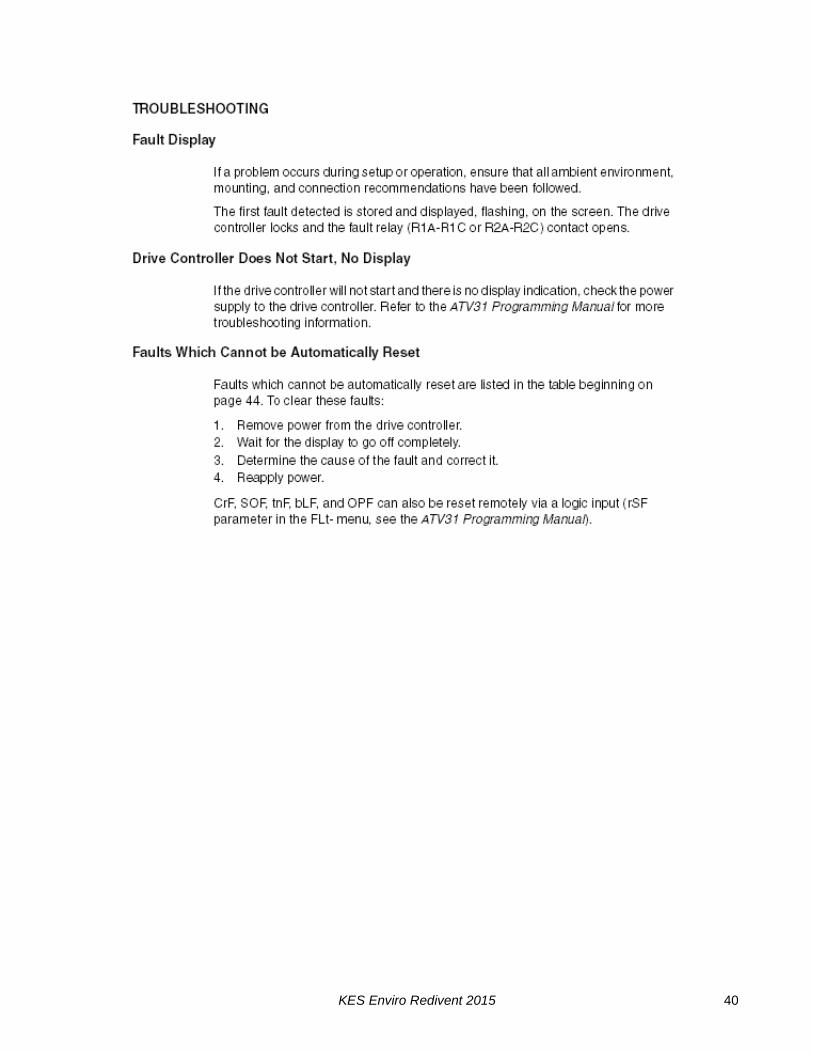
TROUBLE SHOOTING
I. Exhaust fan does not run.
Reset the system once. Press the reset button in the LV10 J-Box or turn the fan selector switch to “OFF” and “ON”. Observe the sequence that follows.
1.The fan does not start and there is no indication on remote panel.
a)Check power from the breaker to the RPD-KW panel. b)Check the three wiring connection from the wash panel to the RPD-KW panel.
2.The fan does not start but the green normal pilot energizes for 30 seconds goes out
and “Filter removed” pilot energizes.
a)Check wiring between KES filter box LV10 J-box terminals 5 & 4 and the KESF fan motor starter. b)Check wiring between the RPD10 or RPW10 remote and the KES-ISH LV10 J-Box c)Reset the exhaust fan overload in the exhaust fan motor starter on the KESF fan section. d)Check three phase power to the KESF fan section disconnect. e)Check if exhaust duct access door is open between the KES filter section and hood. f)Check that all filters on in place. g)Check if the prefilter or box filter access door on the KES unit is open h)Check the Filter Removed alarm settings on logo in RPD. The switch must make and close after
30 seconds of operation. Adjust the pressure setting or replace transducer. i)If all the filters are in place check if pressure tips on the end of the pressure switch manifolds are
plugged. There is a pressure tip in front and behind each filter. j)Measure Exhaust air volume. If low increase fan RPM to within FLA of fan motor k)Check KESF exhaust fan motor starter coil. Replace or repair. l)Check KESF fan belts if loose or broken. m)Check KESF exhaust fan motor. Replace or repair.
.
3.The exhaust fan runs for 30 seconds then shuts off and one of the Filter Clogged
pilots energizes.
a.Check the wiring from the LV10-J-Box to the pressure transducer b.Check pressure transducer operation on P1, P2 & Ps on logo in RPD. Ax vales should be flashing
changes in value. If not, check transducer terminals for MA readings. If MA signal is present at transducer, check wiring at terminals and re-check cat 5 cable.
c.Check the wiring between the RPD10 or RPW10 panel and the LV10 J-Box.
KES Enviro Redivent 2015 19
II. Low Exhaust Air
1.Exhaust fan is running but exhaust air is low.
a)Check if fan belts are slipping. Tighten if necessary. b)Check if fusible link fire damper has closed in the KES filter section. Replace fusible link. c)Check if filters are dirty but have not activated the “Filter Clogged” pilot. Replace dirty filters.
d)Check for correct fan rotation. To correct fan rotation switch two of the high voltage wires motor starter load sider or at the motor disconnect.
III. Filter Clogged Pilot On.
1.Filter clogged pilot indicates which filter section has plugged. Replace filter and reset system. 2. If the filter clogged activates earlier then the normal established schedule reset the pressure
switches. If the kitchen usage or product has not changed, reset the pressure transducer alarms to slightly higher limits for clog on and clog off allowing 25 points difference. Pre-filter clog should be on 1.25 off 1.00 bag. Filter clog should be on 1.75 off 1.50. Box filter clog should be on 2.50 off 2.25.
IV. Filter Removed Pilot On.
1.A filter has been removed or access door left open. Replace if necessary.
V. Fire Pilot On.
1.The fire stat in the KES filter section exhaust outlet has activated and shut the KES system down. If a fire is not present check calibration of firestat TH1. Firestat should be set at 160F (105C).
If operation problems persist check the individual the connection between the RPD10 or RPW10 panel and the LV10 J-Box. If problems still exist contact an authorized SPRING AIR SYSTEMS service technician.

KES Enviro Redivent 2015 20
KES MAINTENANCE SCHEDULE
Every two weeks: See “When to Change Filter Section”
1.Inspect the prefilters. Replace if necessary. It is important to maintain clean prefilters. Replacing the inexpensive prefilters often extends the life of the bag and box filters and reduces unnecessary down time due to clogged filter shutdowns. The RPD or RPW annunciation panel will indicate separately when the “prefilter”, “bag” and “box” filters are clogged. When this occurs the unit shuts down. Rotate the override switch to energize the system for about 4 hours. This provides time to change the filters after the day of cooking. This is a final dirty filter warning. The filter life of all the filters is constant for each operation. Once the approximate filter life for your application is determined we recommend that a regular filter change schedule be set up before the filter out switches activate.
Every Month: “When to Change Filter Section”
1.Complete the two-week list. 2.Inspect the exhaust fan belt for correct tension and wear. All belts usually require
adjustment at this time. Failure to tighten may result in the belt falling off and no airflow. 3.Inspect the bag filters (2nd stage filtration). Replace if necessary. The life of the bag filter
depends on the type of cooking equipment and exhaust hood system. For heavy cooking applications the bag filters may require replacement every month.
4.(Odor Spray Option) Inspect the odor spray bottle. Refill if necessary. At startup the odor spray is adjusted to the desired level. The amount of odor spray used varies with this initial setting. It is important to inspect the level in the bottle every two weeks until the normal rate of use is determined.
Every Three Months: “When to Change Filter Section”
1.Complete the two-week and monthly checklist. 2.Inspect the exhaust fan belt for correct tension and wear. Adjust if necessary. 3.Inspect the box filters (3rd stage filtration). Replace if necessary. Once again the life of
the box filter depends on the type of cooking equipment and exhaust hood system. The box filter may provide one year of service on most applications with high efficiency water wash ventilators.
4.Inspect all electrical connections. Tighten if necessary. 5.Test the filter-removed circuit. Open the prefilter access door while the KES unit is in
operation. The unit should shut down and indicate a filter-removed condition.
Every Six Months “When to Change Filter Section”
1.Complete the two-week, monthly and three month check list. 2.Open the fan wheel access door or hatch on the KES fan section. Inspect the fan wheel
for grease build up. Clean as required. 3.Inspect the exhaust inlet fire damper and fusible link. Replace link annually. 4.Check the motor and fan bearings for noise or overheating. 5.(Odor Pellet Option) Inspect the condition of odor media. 6.The odor media pellets can be checked for remaining life by sending a sample to an
accredited test laboratory. Most major filter suppliers have access to such service. Replace media if required. To replace the media remove the cells from the KES unit. Open the side panel on each odor cell and pour out the used media. Refill the cells with new media. Shake cells while filling to allow pellets to settle evenly in the cell. Note: Do not allow odor media to come in contact with water, as this will immediately render the pellets useless.

KES Enviro Redivent 2015 21
Fan Bearings
1.STY and FYC bearings are factory pre-lubricated lifetime sealed and require no further lubrication.
2.SY and FY bearings are pre-lubricated and equipped with pressure grease fittings for re-greasing.
3.Under normal service conditions grease after six months of operation.
Motor Bearings:
1.All motors leave the factory with bearings custom greased for many years of service under most conditions.
2.Re-greasing of motors depends on the application and is best left to trained service technicians.
3.Periodically check if motor is running hotter then normal.
Centrifugal Exhaust Fan:
1.Make sure the wheel rotates freely before startup. 2.Inspect and clean the wheel periodically. 3.If dirt is allowed to build up the wheel could become out of balance and cause premature
bearing wear. 4.A noisy fan is a typical sign of a fan out of balance.
V-Belt Drives:
1.ALWAYS KEEP SPARE SET OF BELTS. Periodically check the belt tension and adjust if necessary.
2.Some slack should be left in the belt, typically 1/4” per foot of belt from the fan to the motor sheave.
3.Always replace the complete set of belts to ensure even tension and wear. When replacing belts loosen the motor mounts.
4.Do not force belts over sheaves.
RECOMMENDATION
TO ENSURE TROUBLE FREE OPERATION FOR YOUR KITCHEN EXHAUST SYSTEM A PROPER PREVENTATIVE MAINTENANCE PROGRAM IS NECESSARY. SPRING AIR RECOMMENDS THAT A YEARLY SERVICE CONTRACT BE SET UP WITH A REPUTABLE SERVICE ORGANIZATION. THIS WILL REDUCE UNEXPECTED DOWN TIME TO A MINIMUM.
KES Enviro Redivent 2015 22
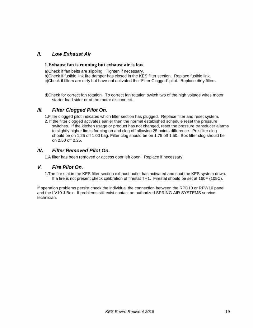
PROGRAMMING THE SMART CLOCK
until the correct day appears.
switch is on. Just rotate the switch and the correct display will blink.If the SERVICE FILTERS WITHIN 4 HOURS displays instead the OVERRIDE
until correct year appears.
Press to move to day.
until correct day appear. Press to
7. To change the date press again. The month will be highlighted. Press
until correct minutes appears.
Press to move to minutes.
6. To change the time press once. The hour will be highlighted. Press
1. When power is first applied to the RPD10 panel the following display will blink
>Stop
Su 06:1601. 06. 03
Su 06:16Set Clock
MM.DD.YY01. 06. 03
Set Clock
MM.DD.YY01. 01. 00
Th 00:00
Su 06:16
01. 01. 00MM.DD.YY
Set Clock
Set Clock
MM.DD.YY01. 01. 00
Th 00:00
Set ClockSu 00:00
01. 01. 00MM.DD.YY
Prg Name>Set Clock
Set Parma
Set ClockSet Parma
Prg Name
Stop
to return to the operating screen.
8. You have finished setting the clock.
move to year. Adjust the year by pressing
Adjust the day by pressing
until the correct month appears.
Adjust the minutes by pressing
until the correct hour appears.
7. Press andOK ESC
or
or
or
or
or
5. To change the day press
4. Press and the following screen will appear.
2. Press and the following screen will appear.
OK
3. Press twice.
OK
Su 00:0001.01.00
ESC
1 2
Q1 Q2
1 2
Q3
1 2
01.01.00Su 00:00
221
Q4
1
Q3
1 2
Q4
2
AUX!
OK
1
Q1
1
Q2
2
RUN/STOP
I6
Setting the Day and Time
L N I2I1 I3 I4 I5 I7 I8 L N I2I1 I3 I4
SMART
Setting the clock on RPD10A automatic panels
Figure 19
KES Enviro Redivent 2015 23
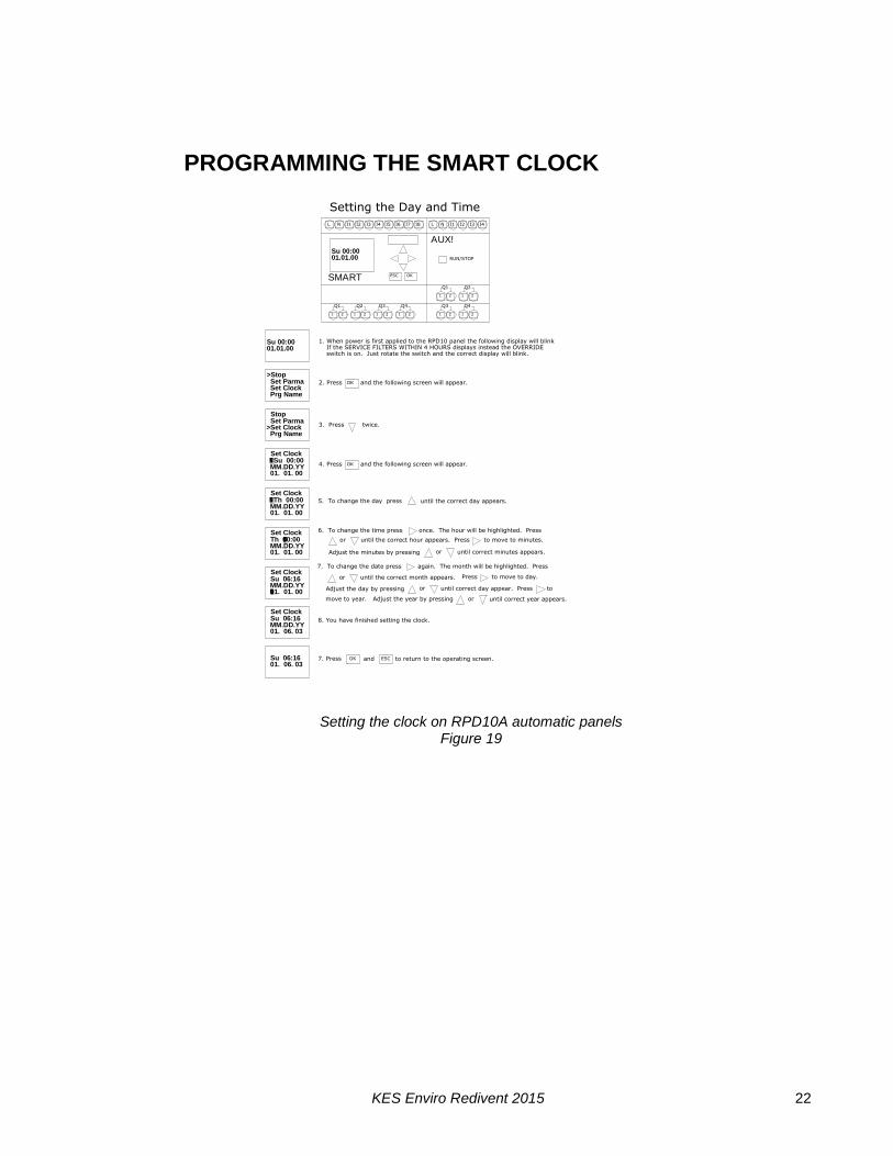
to program a second (Weekend Operation) or third weekly setting go the the section
You have completed programming one weekly fan "On" and "Off" cycling. If you wish
12. If your selection is complete press and to return to the operating screen.
10. Press to move to the hour that the fan will stop in the evening. Press
to change the hour you want the fan to stop each evening. Press to move
to the minute the fan stop in the evening. Press to change the minutes.
to the minute the the fan will start in the morning. Press to change the minutes.
to change the hour you want the fan to start in each morning. Press to move
9. Press to move to the hour that the fan will start in the morning. Press
fan will not automatically operate on Monday, Saturday or Sunday.
not required to operate on that given day. The screen on the left indicates the
7. Press to remove Monday from the weekly schedule. The - dash indicates
The cursor will move to M = Monday.
5. The clock has been factory set to turn the fan on at 6:00 a.m. and off
8. Press to move to the next day of the week. Press each time the fan is
Setting the Weekend Fan "ON" and "OFF" times
Su 06:1601. 06. 03
B04: No1D = MTWTF- -On = 06: 30Off = 22: 30
D = - TWTF- -B04: No1
On = 06: 30Off = 2 3: 00
On = 0 6: 00
B04: No1D = - TWTF- -
Off = 23: 00
B04: No1
On = 06: 00Off = 23: 00
D = - TWTF- -
"Setting Weekend Operation"
11.Press
OK
ESC ESC
B04: No1
Off = 23: 00
D =MTWTFSSOn = 06: 00
B04: No1D =MTWTFSSOn = 06: 00Off = 23: 00
Off = 23: 00On = 06: 00D =MTWTFSSB04: No1
01. 06. 03Su 06:16
>Set Parma
Prg NameSet Clock
Set ParmaSet ClockPrg Name
Off = 23: 00On = 06: 00D = MTWTF-SB04: No1
Stop
>Stop
until the B04: No1 timer appears. This is the
time setting for start and stop each weekday.
the fan will not start automatically any given day.
at 23:00 hours or 11:00 p.m.
6. To change the above settings press
4. Press
OK
2. Press once.
3. Press
OK
1. Press ESC
Setting the Week Day Fan On and Off Timers on RPD10A automatic panels
Figure 20

KES Enviro Redivent 2015 24
6. Press five times to move to Saturday. Press to turn fan on Saturday.
7. Press to move to the hour that the fan will start in the morning. Press
to change the hour you want the fan to start in each morning. Press to move
to the minute the the fan will start in the morning. Press to change the minutes.
to the minute the fan stop in the evening. Press to change the minutes.
to change the hour you want the fan to stop each evening. Press to move
8. Press to move to the hour that the fan will stop in the evening. Press
If your selection is complete press and to return the9. Press
operating screen.
10. You have completed programming weekend fan "On" and "Off" cycling. 01. 06. 03Su 06:16
B04: No2
On = 10: 00D = - - - - - SS
B04: No2
Off = - - : - -
Off = 23: 30
D = - - - - - SSOn = 10: 00
OK ESC ESC
Press once to move to Sunday. Press to turn fan on Sunday.
4. Press
time setting for start and stop each weekday.
1. Press
OK
3. Press
2. Press once.
Setting Weekend Operation
5. Press to program the weekend operation.
Prg Name
B04: No2D = - - - - - SSOn = - - : - -Off = - - : - -
B04: No2D = - - - - - SS
Off = - - : - - On = - - : - -
D = - - - - - - -B04: No2
Off = - - : - - On = - - : - -
On = - - : - -D = - - - - - - -
Off = - - : - -
B04: No2
01. 06. 03
>Set ParmaSet Clock
Stop
Set ParmaSet ClockPrg Name
>Stop
Su 06:16
until the B04: No1 timer appears. This is the
OK
ESC
Setting the and Weekend Fan On and Off Timers on RPD10A automatic panels Figure 21
KES Enviro Redivent 2015 25
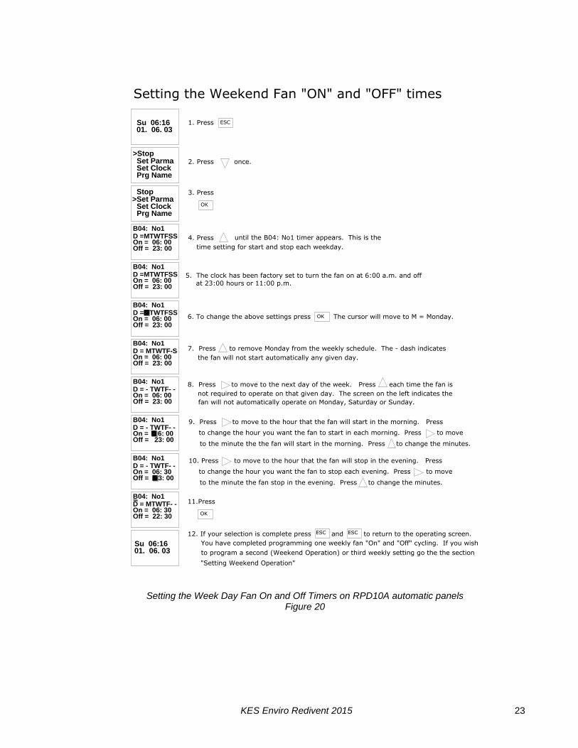
SETTING THE FILTER OUT LIMITS AT STARTUP The Filter OUT PCL setting for each KES unit may have to be adjusted during startup because each commercial kitchen exhaust system total pressure is not the same. The Filter Out (PRE OFF, BAG OFF and BOX OFF) settings must be adjusted below the current pressure reading (Ax) for the Pre-filter, Bag Filter and Box Filter transmitter in the LV20 RPD. All functions are controlled by the PLC located in the RPD-KD or RPD-KW remote panel located in the kitchen area. The LV10 PLC interlocks to the RPD-KD or RPD-KW panel. Note: Only the Filter Out limits for Pre-Filter (PRE O), Bag (BAG O) and Box (BOX O) filters must be checked at startup. The Filter Clogged limits are factory preset for the factory supplied filters. The P1 (Pre-filter), and P2 (Bag Filter) transmitters send a 4-20 ma signal to the Auxiliary 1 module attached to the PLC. The P3 (Box Filter) transmitter signals a 4-20 ma signal to the Auxiliary 2 module located next to Auxiliary 1 module. The PLC converts the 4-20 milliamp signals to a static pressure value. GETTING STARTED Turn on the KES. Override the KES unit. The override switch is found on the remote RPD-KD or RPD-KW. When the KES is in override an amber pilot light on the RPD-KD or RPDW-KW will flash. Open the RPD panel located in the kitchen. Proceed with caution as the panel is powered. When looking at the PLC screen in the LV10 for the first time it displays the date and time as shown in Figure 35. This is the main screen which serves as the basis for the following steps. If date and time is incorrect, refer to “setting the day and time” segment at the beginning of programming the logo.
Figure 22
- If you do not see this screen then press the button on the LOGO until the screen in Figure 35 appears. If
pressing the button once does not take you to this screen, press it again until you see this screen.
- If the above procedure doesn’t work then try the or
buttons to get to this main screen.

KES Enviro Redivent 2015 26
VIEWING THE PARAMETERS To set any parameter you must be on the Main Screen in Figure 35 to continue.
Figure 23 FILTER OUT PARMETERS The limits for the filter out are factory preset for each filter. You must verify that these limits are correct when the filter out does not activate properly. The Ax variable on each screen is the current pressure reading through the filter section. The current reading (Ax) must be higher than the “Off” limit setting for that filter. This limit determines whether the filter is out. To check if the off limit is correct take the filter out. You will see a screen on the PLC displaying the static pressure the filter out occurred and the filter out pilot light on the RPD-K will turn on. Put the filter back in. This has to be done for each type of filter individually in the KES. Note: The values you set in the PLC MUST BE 100 times the actual static pressure. For example if you want the actual pressure limit to be 0.35” W.C., you need to input 35 in the PLC. SETTING PRE-FILTER OUT (PRE O) Factory Presets On = -10 Off = 5 Ax = Current reading through this filter section with filter still in.
Figure 24
- Press the button to show the screen in Figure
36. Press the button to select “Set Param” option
and press .
- Press the button twice to proceed to the screen in Figure 37
- Press the button to get into the editor and then use
the & buttons to navigate and & buttons to change values.
- Press the button to save your changes.
- Press the button twice to proceed to the next screen in Figure 38.
KES Enviro Redivent 2015 27
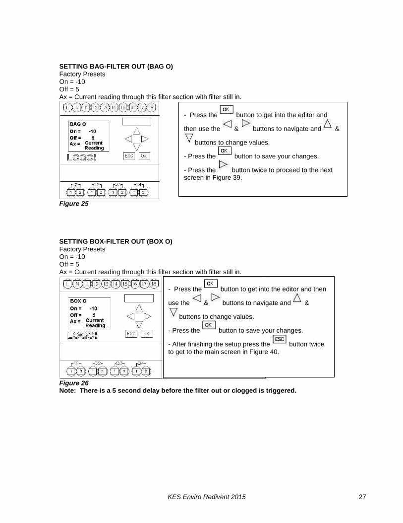
SETTING BAG-FILTER OUT (BAG O) Factory Presets On = -10 Off = 5 Ax = Current reading through this filter section with filter still in.
Figure 25 SETTING BOX-FILTER OUT (BOX O) Factory Presets On = -10 Off = 5 Ax = Current reading through this filter section with filter still in.
Figure 26 Note: There is a 5 second delay before the filter out or clogged is triggered.
- Press the button to get into the editor and
then use the & buttons to navigate and &
buttons to change values.
- Press the button to save your changes.
- Press the button twice to proceed to the next screen in Figure 39.
- Press the button to get into the editor and then
use the & buttons to navigate and &
buttons to change values.
- Press the button to save your changes.
- After finishing the setup press the button twice to get to the main screen in Figure 40.

KES Enviro Redivent 2015 28
SETTING THE FILTER CLOGGED The limits for the filter clogged settings are factory preset. These settings are the filter manufacturer recommended pressure limit at which the filters no longer continue operate efficiently. If you are replacing filters with an alternative manufacturer make sure you enter the new manufacturers pressure limits. To change the filter clogged parameters go to screen in Figure 40 by following steps shown at the beginning of filter out setting section.
Figure 27 SETTING THE PRE-FILTER CLOGGED Factory Presets On = 125 Off = 75 Ax = Current reading through this filter section with filter still in.
Figure 28
- Press the button to select “Set Param” option
and press . - You will see screen shown in Figure 41.
- Press the button and then use the &
buttons to navigate and & buttons to change values.
- Press the button to save your changes.
- Press the button twice to proceed to the next screen in Figure 42

KES Enviro Redivent 2015 29
SETTING THE BAG-FILTER CLOGGED Factory Presets On = 175 Off = 150 Ax = Current reading through this filter section with filter still in.
Figure 29 SETTING THE BOX-FILTER CLOGGED Factory Presets On = 250 Off = 225 Ax = Current reading through this filter section with filter still in.
Figure 29
- Press the button to and then use the &
buttons to navigate and & buttons to change values.
- Press the button to save your changes.
- Press the button twice to proceed to the next screen in Figure 43
- Press the button to get into the editor and then use
the & buttons to navigate and & buttons to change values.
- Press the button to save your changes.
- After finishing the setup press the button twice to get to the main screen in Figure 35
KES Enviro Redivent 2015 30
APPENDIX
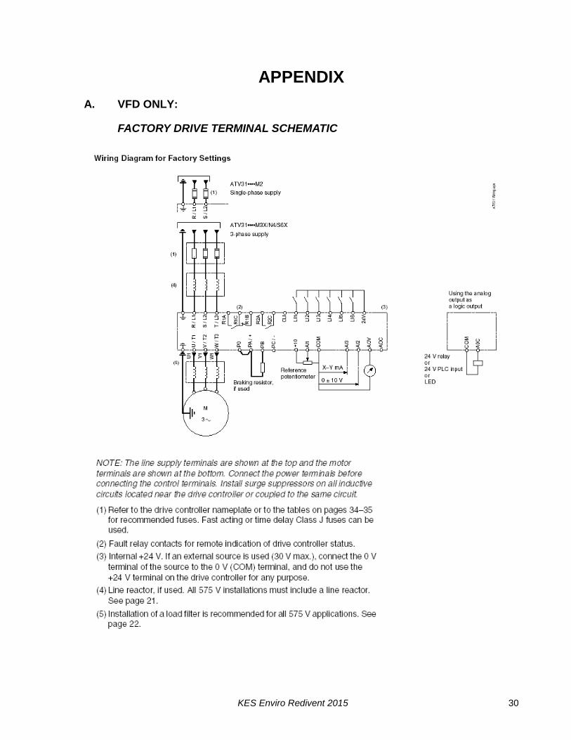
A. VFD ONLY:
FACTORY DRIVE TERMINAL SCHEMATIC
KES Enviro Redivent 2015 31
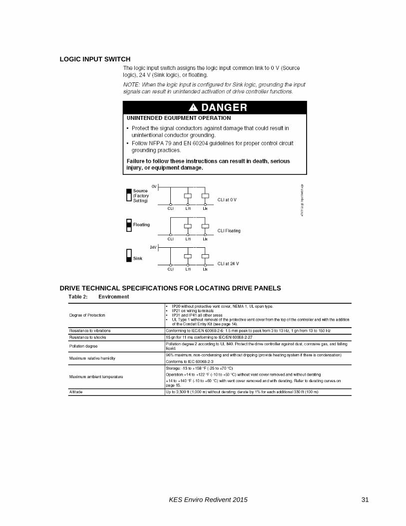
LOGIC INPUT SWITCH
DRIVE TECHNICAL SPECIFICATIONS FOR LOCATING DRIVE PANELS
KES Enviro Redivent 2015 32
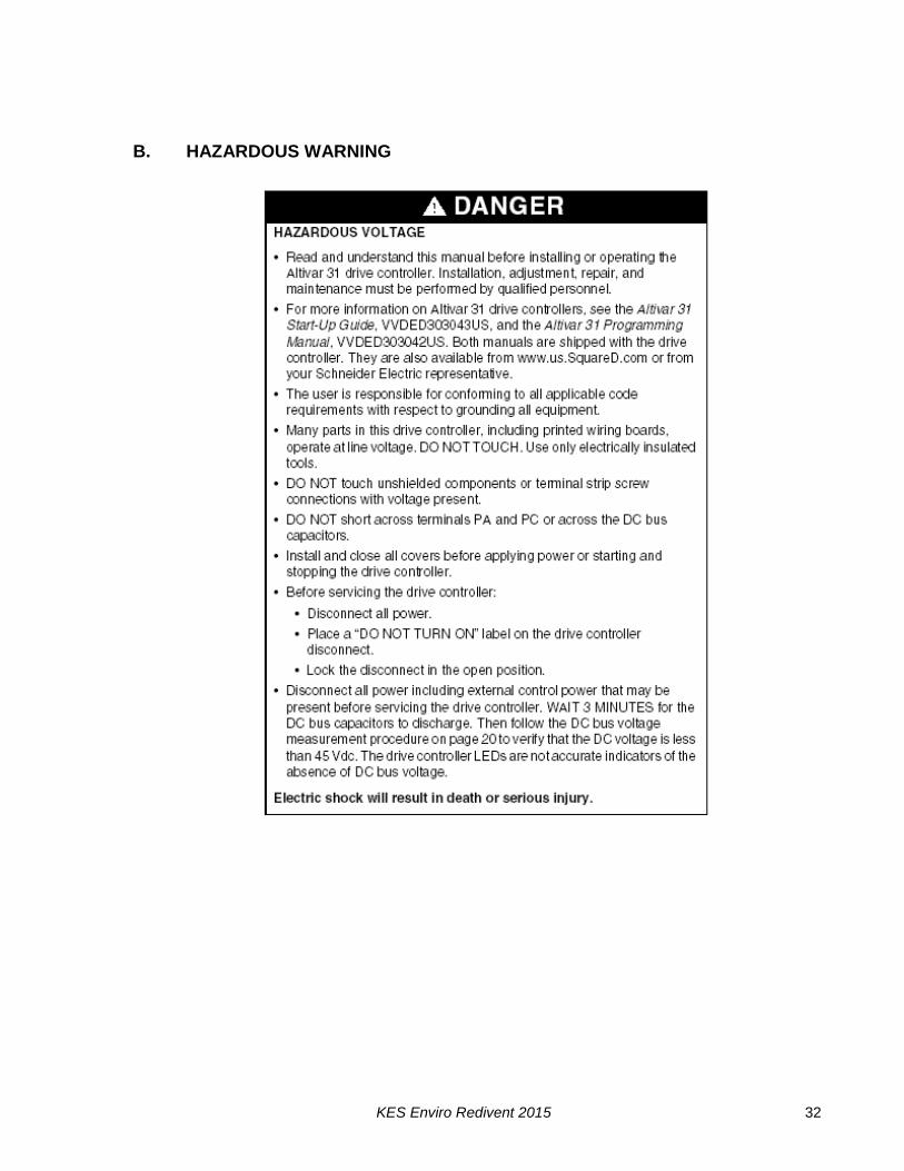
B. HAZARDOUS WARNING
KES Enviro Redivent 2015 33
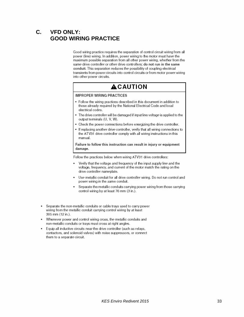
C. VFD ONLY: GOOD WIRING PRACTICE
KES Enviro Redivent 2015 34
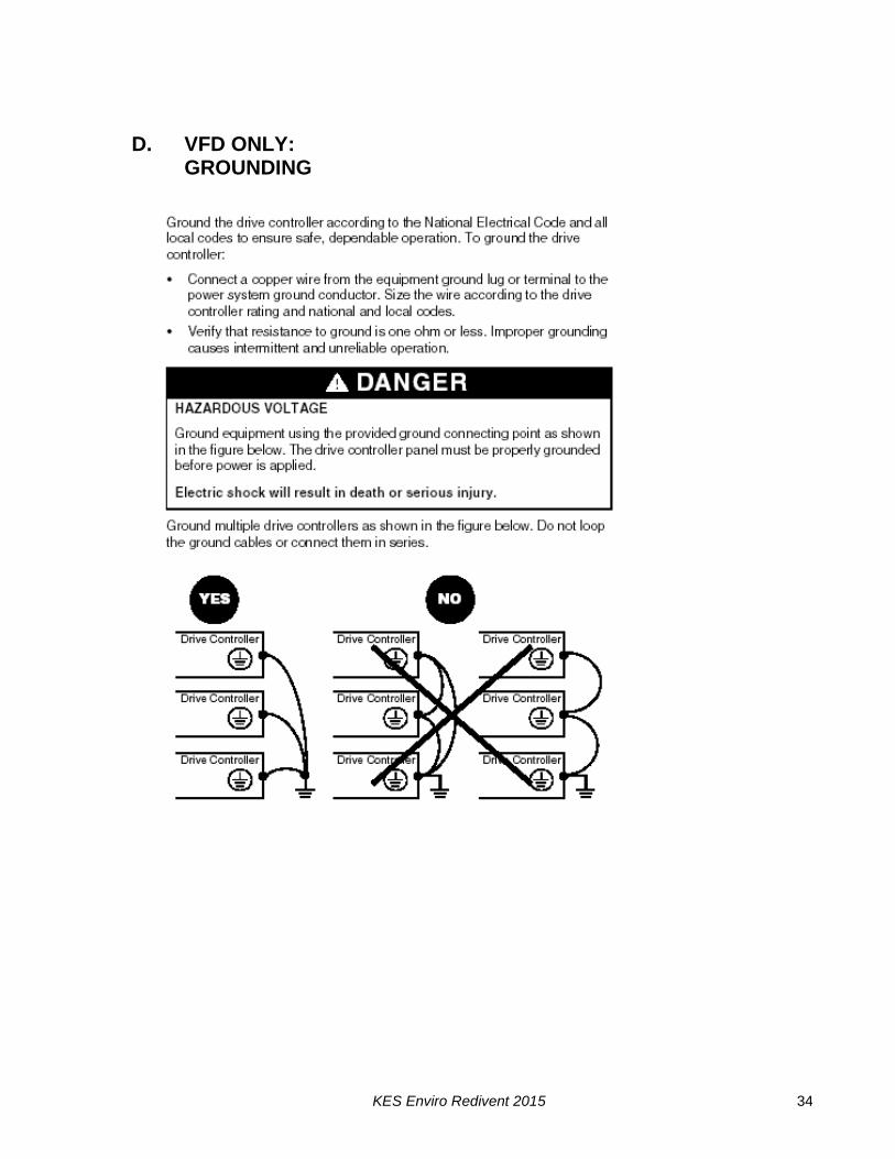
D. VFD ONLY:
GROUNDING
KES Enviro Redivent 2015 35
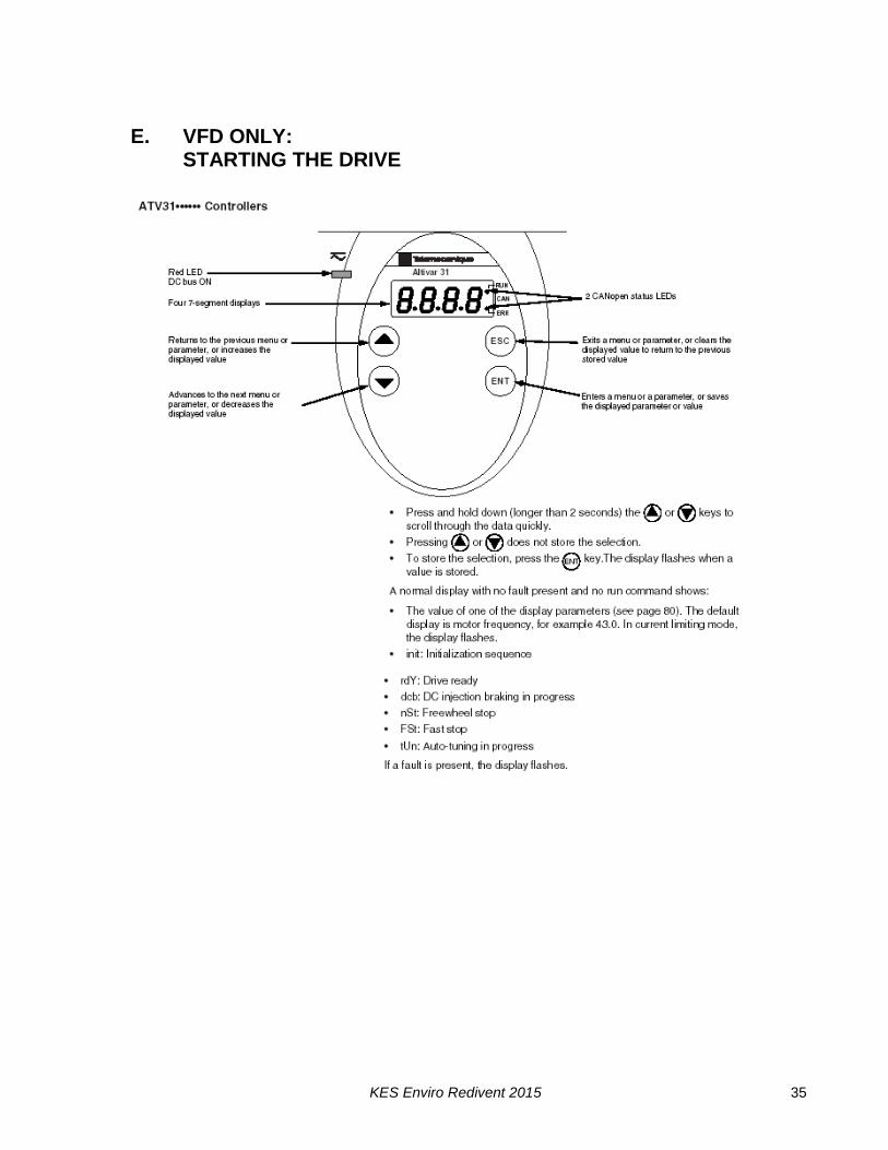
E. VFD ONLY: STARTING THE DRIVE
KES Enviro Redivent 2015 36
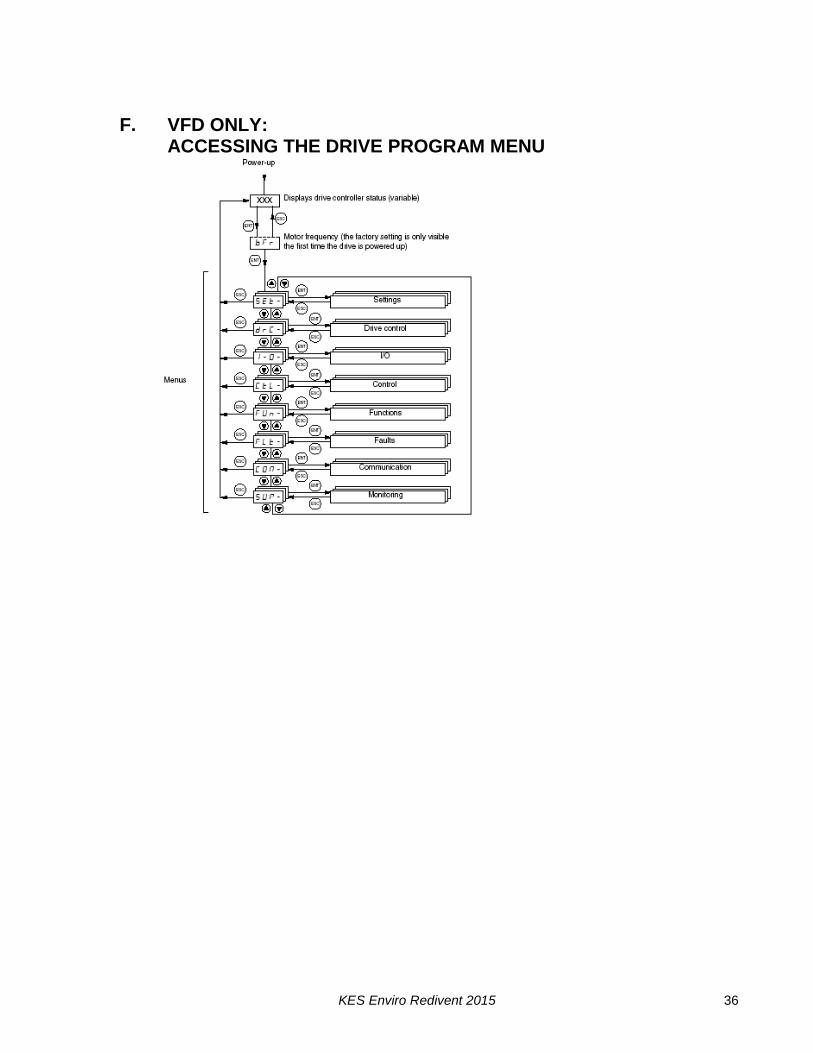
F. VFD ONLY: ACCESSING THE DRIVE PROGRAM MENU

KES Enviro Redivent 2015 37

KES Enviro Redivent 2015 38
G. VFD ONLY PROGRAMMING THE DRIVE PARAMETERS
MXFLOW Programming the variable speed Tele drive
Code Long Label Factory Setting Tele Default
Fast Settings
ACC Acceleration ramp time 10.0s 3.0s
BFR Standard motor frequency 60HZ 50HZ
DEC Deceleration ramp time 10s 3s
ITH Motor thermal current Motor FLA 0.0A
**LSP Low Speed 50HZ 0.0HZ
Motor Control
NSP Nominal Motor Speed 1725 rpm of motor 1715tr/min
TUN Automatic Tuning Autotune on Power up Not Assigned
Terminal Configuration
AOIT Configuration of AOI 4-20mA 0-20mA
DO AOC/AOV Assignment Motor Frequency Not Assigned
R1 Relay R1 Drive Running Drive Fault
RRS Reverse Not Assigned Logic Input LI2
Control Command
FR1 Configuration reference 1 Analog Input AI3 Analog input AI1
LAC Function Access Level Advance Function & Mixed ctrl
Access to Std. Function
Input Summary
AI1A Configuration of AI1 CH. In forced local Mode Configuration ref. 1
AI2A Configuration of AI2 Not Assigned Summing Input 2
AI3A Configuration of AI3 Configuration ref. 1 Not Assigned
LI2A Config. Logic Input 2 Select 2 Preset Speed Reverse
LI3A Config. Logic Input 3 Select 3 Preset Speed Select 3 Preset Speed
LI4A Config. Logic Input 4 Select 4 Reset Speed Select 4 Preset Speed
Fault Behavior
ATR Automatic Restart YES NO
DRN Derating for Undervoltage YES NO
Application Functions
SA2 Summing Input 2 Not Assigned Analog Input AI2
SA3 Summing Input 3 Not Assigned Not Assigned
SDC2 DC Current at Standstill 2 Motor Amp 0.0A
SP2 Preset Speed 2 60HZ 10HZ
SP3 Preset Speed 3 30 HX(optional) 15HZ
SP4 Preset Speed 4 50HZ (optional) 20HZ
Device Reference must be observed when programming Parameter list based on ALTIVAR31 Motor Characteristics must be inputted (ie FLA, RPM) Preset Speeds are adjustable.

KES Enviro Redivent 2015 39
H. VFD ONLY: TROUBLE SHOOTING AND DRIVE FAULT DISPLAY
KES Enviro Redivent 2015 40

KES Enviro Redivent 2015 41

KES Enviro Redivent 2015 42
KES Enviro Redivent 2015 43
KES Enviro Redivent 2015 44
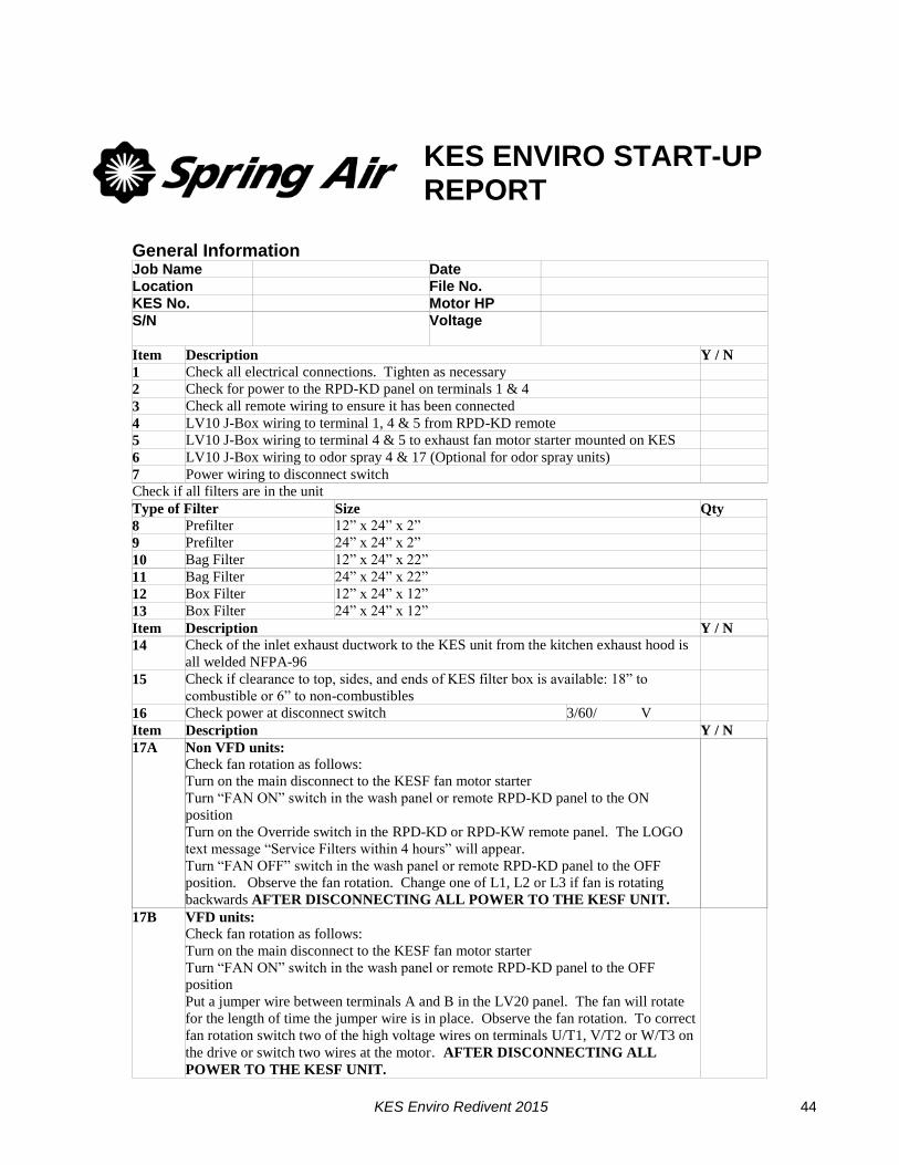
KES ENVIRO START-UP REPORT
General Information Job Name Date Location File No. KES No. Motor HP S/N Voltage
Item Description Y / N
1 Check all electrical connections. Tighten as necessary
2 Check for power to the RPD-KD panel on terminals 1 & 4
3 Check all remote wiring to ensure it has been connected
4 LV10 J-Box wiring to terminal 1, 4 & 5 from RPD-KD remote
5 LV10 J-Box wiring to terminal 4 & 5 to exhaust fan motor starter mounted on KES
6 LV10 J-Box wiring to odor spray 4 & 17 (Optional for odor spray units)
7 Power wiring to disconnect switch
Check if all filters are in the unit
Type of Filter Size Qty
8 Prefilter 12” x 24” x 2”
9 Prefilter 24” x 24” x 2”
10 Bag Filter 12” x 24” x 22”
11 Bag Filter 24” x 24” x 22”
12 Box Filter 12” x 24” x 12”
13 Box Filter 24” x 24” x 12”
Item Description Y / N
14 Check of the inlet exhaust ductwork to the KES unit from the kitchen exhaust hood is
all welded NFPA-96
15 Check if clearance to top, sides, and ends of KES filter box is available: 18” to
combustible or 6” to non-combustibles
16 Check power at disconnect switch 3/60/ V
Item Description Y / N
17A Non VFD units:
Check fan rotation as follows:
Turn on the main disconnect to the KESF fan motor starter
Turn “FAN ON” switch in the wash panel or remote RPD-KD panel to the ON
position
Turn on the Override switch in the RPD-KD or RPD-KW remote panel. The LOGO
text message “Service Filters within 4 hours” will appear.
Turn “FAN OFF” switch in the wash panel or remote RPD-KD panel to the OFF
position. Observe the fan rotation. Change one of L1, L2 or L3 if fan is rotating
backwards AFTER DISCONNECTING ALL POWER TO THE KESF UNIT.
17B VFD units:
Check fan rotation as follows:
Turn on the main disconnect to the KESF fan motor starter
Turn “FAN ON” switch in the wash panel or remote RPD-KD panel to the OFF
position
Put a jumper wire between terminals A and B in the LV20 panel. The fan will rotate
for the length of time the jumper wire is in place. Observe the fan rotation. To correct
fan rotation switch two of the high voltage wires on terminals U/T1, V/T2 or W/T3 on
the drive or switch two wires at the motor. AFTER DISCONNECTING ALL
POWER TO THE KESF UNIT.
KES Enviro Redivent 2015 45
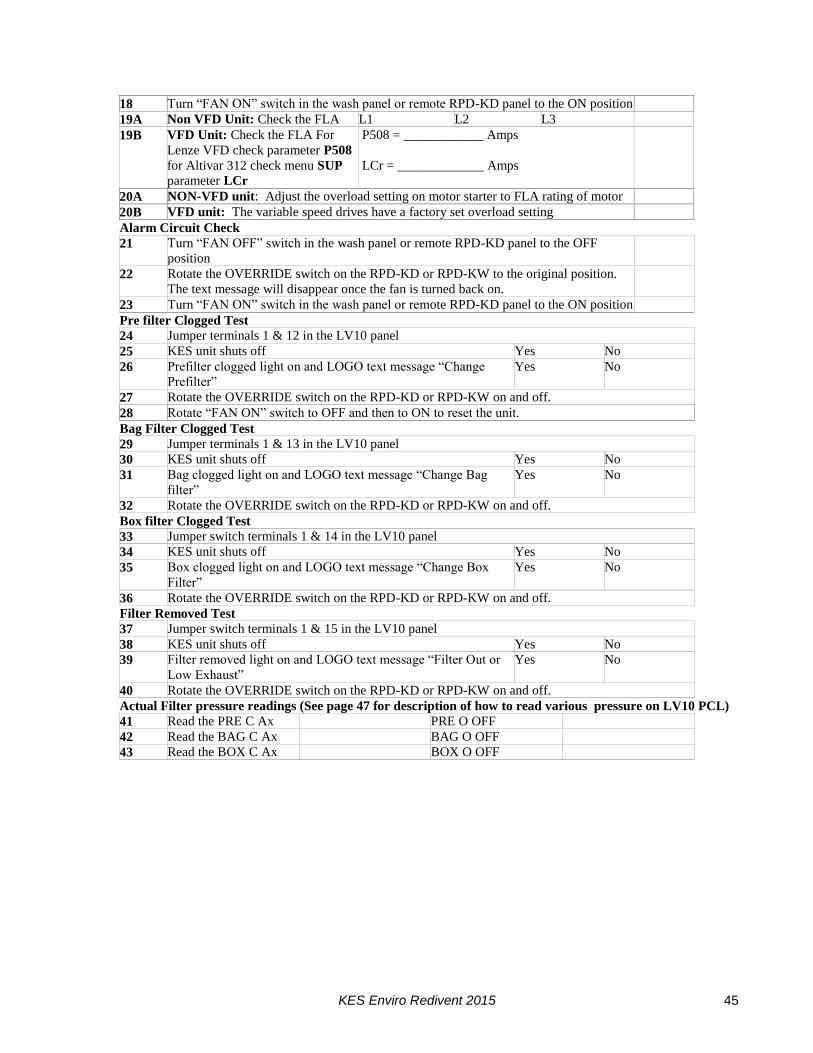
18 Turn “FAN ON” switch in the wash panel or remote RPD-KD panel to the ON position
19A Non VFD Unit: Check the FLA L1 L2 L3
19B VFD Unit: Check the FLA For
Lenze VFD check parameter P508
for Altivar 312 check menu SUP
parameter LCr
P508 = ____________ Amps
LCr = _____________ Amps
20A NON-VFD unit: Adjust the overload setting on motor starter to FLA rating of motor
20B VFD unit: The variable speed drives have a factory set overload setting
Alarm Circuit Check
21 Turn “FAN OFF” switch in the wash panel or remote RPD-KD panel to the OFF
position
22 Rotate the OVERRIDE switch on the RPD-KD or RPD-KW to the original position.
The text message will disappear once the fan is turned back on.
23 Turn “FAN ON” switch in the wash panel or remote RPD-KD panel to the ON position
Pre filter Clogged Test
24 Jumper terminals 1 & 12 in the LV10 panel
25 KES unit shuts off Yes No
26 Prefilter clogged light on and LOGO text message “Change
Prefilter”
Yes No
27 Rotate the OVERRIDE switch on the RPD-KD or RPD-KW on and off.
28 Rotate “FAN ON” switch to OFF and then to ON to reset the unit.
Bag Filter Clogged Test
29 Jumper terminals 1 & 13 in the LV10 panel
30 KES unit shuts off Yes No
31 Bag clogged light on and LOGO text message “Change Bag
filter”
Yes No
32 Rotate the OVERRIDE switch on the RPD-KD or RPD-KW on and off.
Box filter Clogged Test
33 Jumper switch terminals 1 & 14 in the LV10 panel
34 KES unit shuts off Yes No
35 Box clogged light on and LOGO text message “Change Box
Filter”
Yes No
36 Rotate the OVERRIDE switch on the RPD-KD or RPD-KW on and off.
Filter Removed Test
37 Jumper switch terminals 1 & 15 in the LV10 panel
38 KES unit shuts off Yes No
39 Filter removed light on and LOGO text message “Filter Out or
Low Exhaust”
Yes No
40 Rotate the OVERRIDE switch on the RPD-KD or RPD-KW on and off.
Actual Filter pressure readings (See page 47 for description of how to read various pressure on LV10 PCL)
41 Read the PRE C Ax PRE O OFF
42 Read the BAG C Ax BAG O OFF
43 Read the BOX C Ax BOX O OFF
KES Enviro Redivent 2015 46
Filter Out Test #1
44 Remove all the bag filters. Shut the access door and turn the unit on. Wait for 30 sec.
45 KES unit shuts off Yes No
46 Filter removed light on and LOGO text message “Filter Out or
Low Exhaust”
Yes No
47 Reset unit at LV10 J-Box reset switch by turning on and off
48 If the unit does not shut off adjust the BAG O OFF setting below the BAG O Ax reading. See
page 47 of manual for description of changing the BAG O OFF setting. Once setting has been
adjusted repeat item 44.
Filter Out Test #2
49 Remove all the box filters. Shut the access door and turn the unit on. Wait for 30 sec.
50 KES unit shuts off Yes No
51 Filter removed light on and RPD-KD or RPD-KW LOGO text
message “Filter Out or Low Exhaust”
Yes No
52 Rotate the OVERRIDE switch on the RPD-KD or RPD-KW on and off.
53 If the unit does not shut off adjust the BOX O OFF setting below the BOX O Ax reading. See
page 47 of manual for description of changing the BOX O OFF setting. Once setting has been
adjusted repeat item 44.
Hi Temperature Switch Test
54 Jumper terminals 1 & 16 in the LV10 J-Box.
55 KES unit shuts off Yes No
56 Fire light on Yes No
57 Rotate the OVERRIDE switch on the RPD-KD or RPD-KW on and off.
Check override switch
58 Turn “FAN OFF” switch in the wash panel or remote RPD-KD panel to the OFF position
59 Jumper terminals 1 & 12 in the RPD-KD or RPD-KW.
60 Turn “FAN ON” switch in the wash panel or remote RPD-KD panel to the ON position
61 After 30 seconds the KES shuts off, the Prefilter Clogged light turns on and the LOGO text
message “Prefilter Clogged” will appear.
62 Rotate the OVERRIDE switch on the RPD-KW or RPD-KD remote panel to the ON position.
63 KES unit turns on Yes No
64 Warning light turns on and the LOGO text message “Service
Filters within 4 hours” will appear.
Yes No
65 Turn “FAN OFF” switch in the wash panel or remote RPD-KD panel to the OFF position
66 Remove the jumper
67 Turn “FAN ON” switch in the wash panel or remote RPD-KD panel to the ON position
68 Rotate the OVERRIDE switch on the RPD-KW or RPD-KD remote panel to the OFF position.
The Warning light goes off and the LOGO text message disappears.
69 Measure the exhaust air volume at each hood
Use hood start up form for this. Adjust air volume to suit with change of pulleys.
70A Non-VFD Units:
To adjust fan speed, check with Spring Air Engineering to determine if sheaves can be adjusted or
changed to increase or reduce as needed.
70B VFD units:
To adjust fan speed, check with Spring Air Engineering to determine if VFD can be sped up or
slowed down. Adjust Parameter P103 for maximum speed setting on Lenze drives. For Altivar
312 VFD’s adjust HSP in SEt menu for maximum speed.
KES Enviro Redivent 2015 47
Comments:
Service Technician:____________________________________________________
Yes I have received a set of Spring Air Systems Inc. maintenance manuals.
Signature ___________________ Print Name _______________________________