kha180 and 240 - allied commercial · page 1 ©2010 corp. 1017-l8 revised 09/2015 kha series...
TRANSCRIPT
©2010 Page 1
Corp. 1017-L8Revised 09/2015
KHA SERIESService Literature 15 / 20 ton
53 / 70 kW
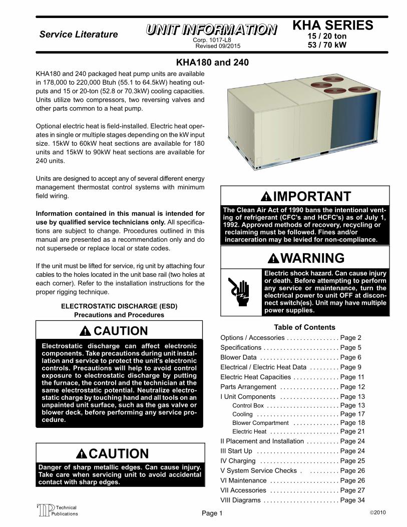
KHA180 and 240KHA180 and 240 packaged heat pump units are available
in 178,000 to 220,000 Btuh (55.1 to 64.5kW) heating out
puts and 15 or 20-ton (52.8 or 70.3kW) cooling capacities.
Units utilize two compressors, two reversing valves and
other parts common to a heat pump.
Optional electric heat is field-installed. Electric heat oper
ates in single or multiple stages depending on the kW input
size. 15kW to 60kW heat sections are available for 180
units and 15kW to 90kW heat sections are available for
240 units.
Units are designed to accept any of several different energy
management thermostat control systems with minimum
field wiring.
Information contained in this manual is intended for
use by qualified service technicians only. All specifica
tions are subject to change. Procedures outlined in this
manual are presented as a recommendation only and do
not supersede or replace local or state codes.
If the unit must be lifted for service, rig unit by attaching four
cables to the holes located in the unit base rail (two holes at
each corner). Refer to the installation instructions for the
proper rigging technique.
CAUTIONElectrostatic discharge can affect electroniccomponents. Take precautions during unit installation and service to protect the unit's electroniccontrols. Precautions will help to avoid controlexposure to electrostatic discharge by puttingthe furnace, the control and the technician at thesame electrostatic potential. Neutralize electrostatic charge by touching hand and all tools on anunpainted unit surface, such as the gas valve orblower deck, before performing any service procedure.
ELECTROSTATIC DISCHARGE (ESD)
Precautions and Procedures
CAUTIONDanger of sharp metallic edges. Can cause injury.Take care when servicing unit to avoid accidentalcontact with sharp edges.
IMPORTANTThe Clean Air Act of 1990 bans the intentional venting of refrigerant (CFC's and HCFC's) as of July 1,1992. Approved methods of recovery, recycling or reclaiming must be followed. Fines and/or incarceration may be levied for non-compliance.
WARNINGElectric shock hazard. Can cause injuryor death. Before attempting to performany service or maintenance, turn theelectrical power to unit OFF at disconnect switch(es). Unit may have multiplepower supplies.
Table of Contents
Options / Accessories Page 2. . . . . . . . . . . . . . . .
Specifications Page 5. . . . . . . . . . . . . . . . . . . . . . .
Blower Data Page 6. . . . . . . . . . . . . . . . . . . . . . . .
Electrical / Electric Heat Data Page 9. . . . . . . . .
Electric Heat Capacities Page 11. . . . . . . . . . . . . .
Parts Arrangement Page 12. . . . . . . . . . . . . . . . . .
I Unit Components Page 13. . . . . . . . . . . . . . . . . .
Control Box Page 13. . . . . . . . . . . . . . . . . . . . . .
Cooling Page 17. . . . . . . . . . . . . . . . . . . . . . . . .
Blower Compartment Page 18. . . . . . . . . . . . . .
Electric Heat Page 21. . . . . . . . . . . . . . . . . . . . .
II Placement and Installation Page 24. . . . . . . . . .
III Start Up Page 24. . . . . . . . . . . . . . . . . . . . . . . . .
IV Charging Page 25. . . . . . . . . . . . . . . . . . . . . . . .
V System Service Checks Page 26. . . . . . . . . .
VI Maintenance Page 26. . . . . . . . . . . . . . . . . . . . .
VII Accessories Page 27. . . . . . . . . . . . . . . . . . . . .
VIII Diagrams Page 34. . . . . . . . . . . . . . . . . . . . . . .
Page 2
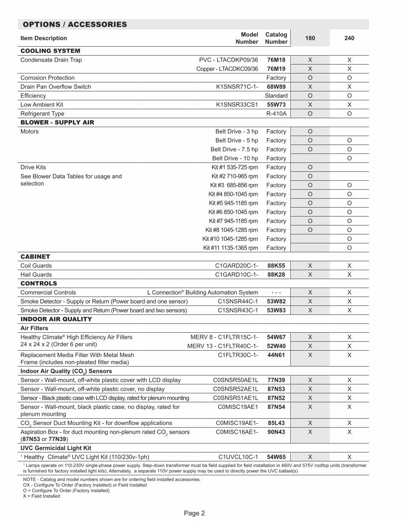
OPTIONS / ACCESSORIES
Item Description Model Number
Catalog Number 180 240
COOLING SYSTEMCondensate Drain Trap PVC - LTACDKP09/36 76M18 X X
Copper - LTACDKC09/36 76M19 X XCorrosion Protection Factory O ODrain Pan Overflow Switch K1SNSR71C-1- 68W89 X XEfficiency Standard O OLow Ambient Kit K1SNSR33CS1 55W73 X XRefrigerant Type R-410A O OBLOWER - SUPPLY AIRMotors Belt Drive - 3 hp Factory O
Belt Drive - 5 hp Factory O OBelt Drive - 7.5 hp Factory O OBelt Drive - 10 hp Factory O
Drive KitsSee Blower Data Tables for usage and selection
Kit #1 535-725 rpm Factory OKit #2 710-965 rpm Factory OKit #3 685-856 rpm Factory O O
Kit #4 850-1045 rpm Factory O OKit #5 945-1185 rpm Factory O OKit #6 850-1045 rpm Factory O OKit #7 945-1185 rpm Factory O O
Kit #8 1045-1285 rpm Factory O OKit #10 1045-1285 rpm Factory OKit #11 1135-1365 rpm Factory O
CABINETCoil Guards C1GARD20C-1- 88K55 X XHail Guards C1GARD10C-1- 88K28 X XCONTROLSCommercial Controls L Connection® Building Automation System - - - X XSmoke Detector - Supply or Return (Power board and one sensor) C1SNSR44C-1 53W82 X XSmoke Detector - Supply and Return (Power board and two sensors) C1SNSR43C-1 53W83 X XINDOOR AIR QUALITYAir FiltersHealthy Climate® High Efficiency Air Filters 24 x 24 x 2 (Order 6 per unit)
MERV 8 - C1FLTR15C-1- 54W67 X XMERV 13 - C1FLTR40C-1- 52W40 X X
Replacement Media Filter With Metal Mesh Frame (includes non-pleated filter media)
C1FLTR30C-1- 44N61 X X
Indoor Air Quality (CO2) SensorsSensor - Wall-mount, off-white plastic cover with LCD display C0SNSR50AE1L 77N39 X XSensor - Wall-mount, off-white plastic cover, no display C0SNSR52AE1L 87N53 X XSensor - Black plastic case with LCD display, rated for plenum mounting C0SNSR51AE1L 87N52 X XSensor - Wall-mount, black plastic case, no display, rated for plenum mounting
C0MISC19AE1 87N54 X X
CO2 Sensor Duct Mounting Kit - for downflow applications C0MISC19AE1- 85L43 X XAspiration Box - for duct mounting non-plenum rated CO2 sensors (87N53 or 77N39)
C0MISC16AE1- 90N43 X X
UVC Germicidal Light Kit1 Healthy Climate® UVC Light Kit (110/230v-1ph) C1UVCL10C-1 54W65 X X
1 Lamps operate on 110-230V single-phase power supply. Step-down transformer must be field supplied for field installation in 460V and 575V rooftop units (transformer is furnished for factory installed light kits). Alternately, a separate 110V power supply may be used to directly power the UVC ballast(s)
NOTE - Catalog and model numbers shown are for ordering field installed accessories. OX - Configure To Order (Factory Installed) or Field Installed O = Configure To Order (Factory Installed) X = Field Installed
Page 3
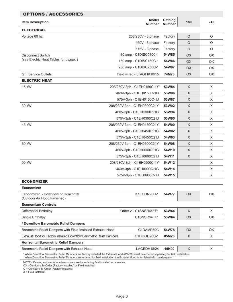
OPTIONS / ACCESSORIES
Item Description Model Number
Catalog Number 180 240
ELECTRICAL
Voltage 60 hz 208/230V - 3 phase Factory O O
460V - 3 phase Factory O O
575V - 3 phase Factory O O
Disconnect Switch (see Electric Heat Tables for usage, )
80 amp - C1DISC080C-1 54W85 OX OX150 amp - C1DISC150C-1 54W86 OX OX250 amp - C1DISC250C-1 54W87 OX OX
GFI Service Outlets Field wired - LTAGFIK10/15 74M70 OX OX
ELECTRIC HEAT
15 kW 208/230V-3ph - C1EH0150C-1Y 53W84 X X
460V-3ph - C1EH0150C-1G 53W86 X X
575V-3ph - C1EH0150C-1J 53W87 X X
30 kW 208/230V-3ph - C1EH0300C21Y 53W92 X X
460V-3ph - C1EH0300C21G 53W94 X X
575V-3ph - C1EH0300C21J 53W95 X X
45 kW 208/230V-3ph - C1EH0450C21Y 54W00 X X
460V-3ph - C1EH0450C21G 54W02 X X
575V-3ph - C1EH0450C21J 54W03 X X
60 kW 208/230V-3ph - C1EH0600C21Y 54W08 X X
460V-3ph - C1EH0600C21G 54W10 X X
575V-3ph - C1EH0600C21J 54W11 X X
90 kW 208/230V-3ph - C1EH0900C-1Y 54W12 X
460V-3ph - C1EH0900C-1G 54W14 X
575V-3ph - C1EH0900C-1J 54W15 X
ECONOMIZER
Economizer
Economizer - Downflow or Horizontal (Outdoor Air Hood furnished)
K1ECON20C-1 54W77 OX OX
Economizer Controls
Differential Enthalpy Order 2 - C1SNSR64FF1 53W64 X X
Single Enthalpy C1SNSR64FF1 53W64 OX OX1 Downflow Barometric Relief Dampers
Barometric Relief Dampers with Field Installed Exhaust Hood C1DAMP50C 54W78 OX OX
Exhaust Hood for Factory Installed Downflow Barometric Relief Dampers C1HOOD20C-1 85M26 X X
Horizontal Barometric Relief Dampers
Barometric Relief Dampers with Exhaust Hood LAGEDH18/24 16K99 X X1 When Downflow Barometric Relief Dampers are factory installed the Exhaust Hood (85M26) must be ordered separately for field installation.
When Downflow Barometric Relief Dampers are ordered for field installation the Exhaust Hood is furnished with the dampers.
NOTE - Catalog and model numbers shown are for ordering field installed accessories. OX - Configure To Order (Factory Installed) or Field Installed O = Configure To Order (Factory Installed) X = Field Installed

Page 4
OPTIONS / ACCESSORIES
Item Description Model Number
Catalog Number 180 240
OUTDOOR AIROutdoor Air DampersMotorized Dampers with Outdoor Air Hood K1DAMP20C-1 58W62 OX OXManual Dampers With Outdoor Air Hood C1DAMP10C-1 54W76 OX OXPOWER EXHAUSTStandard Static 208/230V - C1PWRE10C-1Y 54W70 X X
460V - C1PWRE10C-1G 54W71 X X575V - C1PWRE10C-1J 54W72 X X
ROOF CURBS - DOWNFLOWClip Curb8 in. height C1CURB40CD1 26W32 X X14 in. height LARMF18/30S-14 33K44 X X18 in. height LARMF18/30S-18 33K45 X X24 in. height LARMF18/30S-24 33K46 X XStandard14 in. height LARMF18/36-14 16K87 X X24 in. height LARMF18/36-24 16K88 X XAdjustable Pitched Curb14 in. height L1CURB55C 43W26 X XROOF CURBS - HORIZONTAL (REQUIRES HORIZONTAL RETURN AIR PANEL KIT)Standard26 in. height - slab applications LARMFH18/24-26 97J33 X X37 in. height - rooftop applications LARMFH18/24-37 38K53 X XInsulation Kit For Standard Horizontal Curbsfor LARMFH18/24-26 C1INSU11C-1- 73K32 X Xfor LARMFH18/24-37 C1INSU13C-1- 73K34 X XHorizontal Return Air Panel KitRequired for Horizontal Applications with Roof Curb C1HRAP10C-1- 87M00 X XCEILING DIFFUSERSStep-Down - Order one RTD11-185 29G06 X
RTD11-275-R 29G07 XRTD11-150/180S (Canada only) 13K63 X
RTD11-275S (Canada only) 13K64 XFlush - Order one FD11-185 29G10 X
FD11-275-R 29G11 XFD11-150/180S (Canada only) 13K58 X
FD11-275S (Canada only) 13K59 XTransitions (Supply and Return) - Order one LASRT18 19K01 X
LASRT21/24 19K02 XLASRT18S (Canada only) 33K48 X
LASRT21/24S (Canada only) 33K49 XNOTE - Catalog and model numbers shown are for ordering field installed accessories. OX - Configure To Order (Factory Installed) or Field Installed O = Configure To Order (Factory Installed) X = Field Installed

Page 5
SPECIFICATIONSGeneral Data Nominal Tonnage 15 Ton 20 Ton
Model Number KHA180S4B KHA240S4BEfficiency Type Standard Standard
Blower Type Constant Air Volume CAV
Constant Air Volume CAV
Cooling Performance
Gross Cooling Capacity - Btuh 179,000 226,0001 Net Cooling Capacity - Btuh 174,000 218,000
AHRI Rated Air Flow - cfm 6000 7500Total Unit Power - kW 16.4 20.5
1 EER (Btuh/Watt) 10.6 10.62 IEER (Btuh/Watt) 10.7 10.7
Refrigerant Type R-410A R-410ARefrigerant Charge Furnished
Circuit 1 21 lbs. 0 oz. 26 lbs. 0 oz.Circuit 2 21 lbs. 0 oz. 26 lbs. 0 oz.
Heating Performance
1 Total High Heat Capacity - Btuh 178,000 220,000Total Unit Power - kW 16.1 19.9
1 C.O.P. 3.2 3.21 Total Low Heat Capacity - Btuh 104,000 128,000
Total Unit Power (kW) 14.9 18.31 C.O.P. 2.05 2.05
Electric Heat Available - See page 3 15-30-45-60 kW 15-30-45-60-90 kWCompressor Type (number) Scroll (2) Scroll (2)Outdoor Coils
Net face area (total) - sq. ft. 57.0 57.0Tube diameter - in. 3/8 3/8
Number of rows 1.66 2Fins per inch 20 20
Outdoor Coil Fans
Motor - (No.) horsepower (4) 1/3 (4) 1/3Motor rpm 1075 1075
Total Motor watts 1500 1500Diameter - (No.) in. (4) 24 (4) 24
Number of blades 3 3Total Air volume - cfm 15,450 15,450
Indoor Coils Net face area (total) - sq. ft. 21.4 21.4Tube diameter - in. 3/8 3/8
Number of rows 3 4Fins per inch 14 14
Drain connection - No. and size (1) 1 in. FPT (1) 1 in. FPTExpansion device type Balance port TXV, removable head
3 Indoor Blower and Drive Selection
Nominal motor output 3 hp, 5 hp, 7.5 hp 5 hp, 7.5 hp, 10 hpMaximum usable motor output
(US Only)3.45 hp, 5.75 hp,
8.62 hp5.75 hp, 8.62 hp,
11.5 hpMotor - Drive kit number 3 hp
Kit 1 535-725 rpm Kit 2 710-965 rpm
5 hp Kit 3 685-856 rpm Kit 4 850-1045 rpm Kit 5 945-1185 rpm
7.5 hp Kit 6 850-1045 rpm Kit 7 945-1185 rpm
Kit 8 1045-1285 rpm
5 hp Kit 3 685-856 rpm Kit 4 850-1045 rpm Kit 5 945-1185 rpm
7.5 hp Kit 6 850-1045 rpm Kit 7 945-1185 rpm
Kit 8 1045-1285 rpm 10 hp
Kit 7 945-1185 rpm Kit 10 1045-1285 rpm Kit 11 1135-1365 rpm
Blower wheel nominal diameter x width - in.
(2) 15 x 15 (2) 15 x 15
Filters Type of filter Fiberglass, disposableNumber and size - in. (6) 24 x 24 x 2
Electrical characteristics 208/230V, 460V or 575V - 60 hertz - 3 phaseNOTE - Gross cooling capacity includes evaporator blower motor heat deduction. Net coling capacity does not include evaporator blower motor heat deduction. 1 Certified in accordance with the ULE certification program, which is based on AHRI Standard 340/360: Cooling Ratings - 95°F outdoor air temperature and 80°F db/67°F wb entering indoor coil air. High Temperature Heating Ratings - 47°F db/43°F wb outdoor air temperature and 70°F entering indoor coil air. Low Temperature Heating Ratings - 17°F db/15°F wb outdoor air temperature and 70°F entering indoor coil air. 2 Integrated Energy Efficiency Ratio certified and tested according to AHRI Standard 340/360. 3 Using total air volume and system static pressure requirements determine from blower performance tables rpm and motor output required. Maximum usable output of motors furnished are shown. In Canada, nominal motor output is also maximum usable motor output. If motors of comparable output are used, be sure to keep within the service factor limitations outlined on the motor nameplate.

Page 6
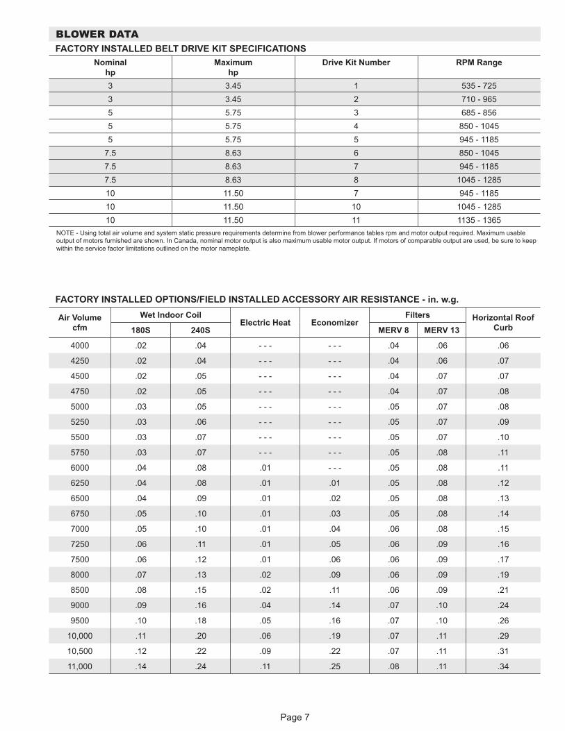
BLOWER DATABLOWER TABLE INCLUDES RESISTANCE FOR BASE UNIT ONLY WITH DRY INDOOR COIL & AIR FILTERS IN PLACE FOR ALL UNITS ADD:
1 - Wet indoor coil air resistance of selected unit. 2 - Any factory installed options air resistance (heat section, economizer, etc.) 3 - Any field installed accessories air resistance (duct resistance, diffuser, etc.)
Then determine from blower table blower motor output and drive required. See page 7 for wet coil and option/accessory air resistance data. See page 7 for factory installed drive kit specifications.MINIMUM AIR VOLUME REQUIRED FOR USE WITH OPTIONAL ELECTRIC HEAT
All units require 6000 cfm minimum air with electric heat.
Air Volume
cfm
TOTAL STATIC PRESSURE - In. w.g.
0.40 0.60 0.80 1.00 1.20 1.40 1.60 1.80 2.00 2.20 2.40 2.60
RPM BHP RPM BHP RPM BHP RPM BHP RPM BHP RPM BHP RPM BHP RPM BHP RPM BHP RPM BHP RPM BHP RPM BHP
4750 575 1.10 660 1.45 740 1.80 810 2.15 870 2.50 930 2.85 985 3.20 1040 3.55 1085 3.90 1135 4.25 1180 4.65 1225 5.00
5000 585 1.25 670 1.60 750 1.95 815 2.30 880 2.70 940 3.05 995 3.40 1045 3.80 1095 4.15 1140 4.50 1185 4.90 1230 5.30
5250 595 1.35 680 1.70 755 2.10 825 2.50 890 2.90 945 3.25 1000 3.65 1050 4.00 1100 4.40 1150 4.80 1195 5.20 1235 5.60
5500 605 1.45 690 1.85 765 2.25 835 2.65 895 3.05 955 3.45 1010 3.85 1060 4.25 1110 4.70 1155 5.10 1200 5.50 1240 5.90
5750 615 1.60 700 2.00 775 2.45 840 2.85 905 3.25 960 3.65 1015 4.10 1065 4.50 1115 4.95 1160 5.35 1205 5.80 1250 6.25
6000 630 1.75 710 2.15 785 2.60 850 3.05 910 3.45 970 3.90 1025 4.35 1075 4.80 1120 5.20 1170 5.65 1215 6.10 1255 6.55
6250 640 1.90 720 2.35 795 2.80 860 3.25 920 3.70 975 4.15 1030 4.60 1080 5.05 1130 5.50 1175 5.95 1220 6.45 1265 6.90
6500 650 2.05 730 2.50 805 3.00 870 3.45 930 3.95 985 4.40 1040 4.85 1090 5.35 1140 5.85 1185 6.30 1225 6.75 1270 7.25
6750 665 2.20 745 2.70 815 3.20 880 3.70 940 4.20 995 4.65 1045 5.10 1095 5.60 1145 6.10 1190 6.60 1235 7.10 1275 7.60
7000 675 2.35 755 2.90 825 3.40 890 3.95 950 4.45 1005 4.95 1055 5.40 1105 5.95 1155 6.45 1200 6.95 1240 7.45 1285 8.00
7250 690 2.60 765 3.10 835 3.65 900 4.15 955 4.65 1015 5.25 1065 5.75 1115 6.25 1160 6.75 1205 7.30 1250 7.85 1290 8.35
7500 700 2.75 775 3.30 845 3.85 910 4.45 965 4.95 1020 5.50 1075 6.05 1125 6.60 1170 7.15 1215 7.65 1260 8.25 1300 8.75
7750 715 3.00 790 3.55 855 4.10 920 4.70 975 5.25 1030 5.80 1080 6.35 1130 6.90 1180 7.50 1225 8.05 1265 8.60 1305 9.15
8000 725 3.20 800 3.80 865 4.35 930 4.95 985 5.50 1040 6.10 1090 6.70 1140 7.25 1185 7.85 1230 8.40 1275 9.00 1315 9.60
8250 740 3.40 810 4.00 880 4.65 940 5.25 995 5.85 1050 6.45 1100 7.05 1150 7.65 1195 8.25 1240 8.85 1280 9.40 1325 10.05
8500 750 3.65 825 4.30 890 4.90 950 5.55 1005 6.15 1060 6.80 1110 7.40 1160 8.05 1205 8.65 1250 9.25 1290 9.85 1330 10.45
8750 765 3.90 835 4.55 900 5.20 960 5.85 1015 6.45 1070 7.15 1120 7.75 1165 8.35 1215 9.05 1255 9.65 1300 10.30 1340 10.90
9000 780 4.20 850 4.85 910 5.50 970 6.15 1025 6.80 1080 7.50 1130 8.15 1175 8.75 1220 9.40 1265 10.10 1310 10.80 1350 11.40
9250 790 4.45 860 5.15 925 5.85 985 6.55 1040 7.20 1090 7.85 1140 8.55 1185 9.20 1230 9.85 1275 10.55 1315 11.20 - - - - - -
9500 805 4.75 875 5.45 935 6.15 995 6.90 1050 7.60 1100 8.25 1150 8.95 1195 9.60 1240 10.30 1285 11.05 - - - - - - - - - - - -
9750 820 5.05 885 5.75 950 6.55 1005 7.20 1060 7.95 1110 8.65 1160 9.40 1205 10.05 1250 10.80 1295 11.50 - - - - - - - - - - - -
10,000 835 5.40 900 6.15 960 6.85 1015 7.60 1070 8.35 1120 9.05 1170 9.80 1215 10.50 1260 11.25 - - - - - - - - - - - - - - - - - -
10,250 845 5.65 910 6.45 970 7.20 1030 8.00 1080 8.75 1135 9.55 1180 10.25 1225 11.00 - - - - - - - - - - - - - - - - - - - - - - - -
10,500 860 6.00 925 6.85 985 7.65 1040 8.40 1095 9.20 1145 10.00 1190 10.70 1235 11.45 - - - - - - - - - - - - - - - - - - - - - - - -
10,750 875 6.40 940 7.25 1000 8.05 1055 8.85 1105 9.65 1155 10.45 1200 11.20 - - - - - - - - - - - - - - - - - - - - - - - - - - - - - -
11,000 890 6.80 950 7.60 1010 8.45 1065 9.30 1115 10.05 1165 10.90 - - - - - - - - - - - - - - - - - - - - - - - - - - - - - - - - - - - -
Page 7
FACTORY INSTALLED OPTIONS/FIELD INSTALLED ACCESSORY AIR RESISTANCE - in. w.g.
Air Volume cfm
Wet Indoor CoilElectric Heat Economizer
Filters Horizontal Roof Curb180S 240S MERV 8 MERV 13
4000 .02 .04 - - - - - - .04 .06 .06
4250 .02 .04 - - - - - - .04 .06 .07
4500 .02 .05 - - - - - - .04 .07 .07
4750 .02 .05 - - - - - - .04 .07 .08
5000 .03 .05 - - - - - - .05 .07 .08
5250 .03 .06 - - - - - - .05 .07 .09
5500 .03 .07 - - - - - - .05 .07 .10
5750 .03 .07 - - - - - - .05 .08 .11
6000 .04 .08 .01 - - - .05 .08 .11
6250 .04 .08 .01 .01 .05 .08 .12
6500 .04 .09 .01 .02 .05 .08 .13
6750 .05 .10 .01 .03 .05 .08 .14
7000 .05 .10 .01 .04 .06 .08 .15
7250 .06 .11 .01 .05 .06 .09 .16
7500 .06 .12 .01 .06 .06 .09 .17
8000 .07 .13 .02 .09 .06 .09 .19
8500 .08 .15 .02 .11 .06 .09 .21
9000 .09 .16 .04 .14 .07 .10 .24
9500 .10 .18 .05 .16 .07 .10 .26
10,000 .11 .20 .06 .19 .07 .11 .29
10,500 .12 .22 .09 .22 .07 .11 .31
11,000 .14 .24 .11 .25 .08 .11 .34
BLOWER DATAFACTORY INSTALLED BELT DRIVE KIT SPECIFICATIONS
Nominal hp
Maximum hp
Drive Kit Number RPM Range
3 3.45 1 535 - 7253 3.45 2 710 - 9655 5.75 3 685 - 8565 5.75 4 850 - 10455 5.75 5 945 - 1185
7.5 8.63 6 850 - 10457.5 8.63 7 945 - 11857.5 8.63 8 1045 - 128510 11.50 7 945 - 118510 11.50 10 1045 - 128510 11.50 11 1135 - 1365
NOTE - Using total air volume and system static pressure requirements determine from blower performance tables rpm and motor output required. Maximum usable output of motors furnished are shown. In Canada, nominal motor output is also maximum usable motor output. If motors of comparable output are used, be sure to keep within the service factor limitations outlined on the motor nameplate.

Page 8
BLOWER DATA
POWER EXHAUST FAN PERFORMANCE Return Air System Static Pressure Air Volume Exhausted
in. w.g. cfm 0.00 86300.05 82100.10 77250.15 71100.20 64700.25 57900.30 50600.35 43000.40 35100.45 26900.50 1840
CEILING DIFFUSER AIR RESISTANCE - in. w.g.
Air Volume
cfm
Step-Down Diffuser Flush DiffuserRTD11-185 RTD11-275
FD11-185 FD11-2752 Ends Open 1 Side/2 Ends
OpenAll Ends & Sides Open 2 Ends Open 1 Side/2 Ends
OpenAll Ends & Sides Open
5000 .51 .44 .39 - - - - - - - - - .27 - - -5200 .56 .48 .42 - - - - - - - - - .30 - - -5400 .61 .52 .45 - - - - - - - - - .33 - - -5600 .66 .56 .48 - - - - - - - - - .36 - - -5800 .71 .59 .51 - - - - - - - - - .39 - - -6000 .76 .63 .55 .36 .31 .27 .42 .296200 .80 .68 .59 - - - - - - - - - .46 - - -6400 .86 .72 .63 - - - - - - - - - .50 - - -6500 - - - - - - - - - .42 .36 .31 - - - .346600 .92 .77 .67 - - - - - - - - - .54 - - -6800 .99 .83 .72 - - - - - - - - - .58 - - -7000 1.03 .87 .76 .49 .41 .36 .62 .407200 1.09 .92 .80 - - - - - - - - - .66 - - -7400 1.15 .97 .84 - - - - - - - - - .70 - - -7500 - - - - - - - - - .51 .46 .41 - - - .457600 1.20 1.02 .88 - - - - - - - - - .74 - - -8000 - - - - - - - - - .59 .49 .43 - - - .508500 - - - - - - - - - .69 .58 .50 - - - .579000 - - - - - - - - - .79 .67 .58 - - - .669500 - - - - - - - - - .89 .75 .65 - - - .74
10,000 - - - - - - - - - 1.00 .84 .73 - - - .8110,500 - - - - - - - - - 1.10 .92 .80 - - - .8911,000 - - - - - - - - - 1.21 1.01 .88 - - - .96
CEILING DIFFUSER AIR THROW DATA
Model No.
Air Volume cfm
1 Effective Throw Range - ft.Model
No.Air Volume
cfm
1 Effective Throw Range - ft.RTD11-185 Step-Down
FD11-185 Flush
RTD11-275 Step-Down
FD11-275 Flush
180
5600 39 - 49 28 - 37
240
7200 33 - 38 26 - 355800 42 - 51 29 - 38 7400 35 - 40 28 - 376000 44 - 54 40 - 50 7600 36 - 41 29 - 386200 45 - 55 42 - 51 7800 38 - 43 40 - 506400 46 - 55 43 - 52 8000 39 - 44 42 - 516600 47 - 56 45 - 56 8200 41 - 46 43 - 52
1 Throw is the horizontal or vertical distance an airstream travels on leaving the outletor diffuser before the maximum velocity is reduced to 50 ft. per minute. Four sides open.
8400 43 - 49 44 - 548600 44 - 50 46 - 578800 47 - 55 48 - 59
Page 9
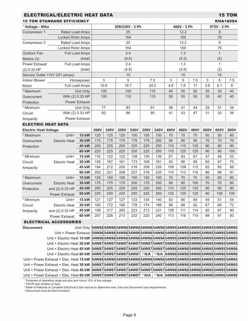
ELECTRICAL/ELECTRIC HEAT DATA 15 TON15 TON STANDARD EFFICIENCY KHA180S41 Voltage - 60hz 208/230V - 3 Ph 460V - 3 Ph 575V - 3 PhCompressor 1 Rated Load Amps 25 12.2 9
Locked Rotor Amps 164 100 78Compressor 2 Rated Load Amps 25 12.2 9
Locked Rotor Amps 164 100 78Outdoor FanMotors (3)
Full Load Amps 2.4 1.3 1(total) (9.6) (5.2) (4)
Power Exhaust(2) 0.33 HP
Full Load Amps 2.4 1.3 1(total) (4.8) (2.6) (2)
Service Outlet 115V GFI (amps) 15 15 15Indoor BlowerMotor
Horsepower 3 5 7.5 3 5 7.5 3 5 7.5Full Load Amps 10.6 16.7 24.2 4.8 7.6 11 3.9 6.1 9
2 MaximumOvercurrentProtection
Unit Only 100 100 110 45 50 50 35 35 40With (2) 0.33 HP
Power Exhaust100 110 110 50 50 50 35 40 40
3 MinimumCircuitAmpacity
Unit Only 77 83 91 38 41 44 29 31 34With (2) 0.33 HP
Power Exhaust82 88 95 41 43 47 31 33 36
ELECTRIC HEAT DATAElectric Heat Voltage 208V 240V 208V 240V 208V 240V 480V 480V 480V 600V 600V 600V2 MaximumOvercurrentProtection
Unit+Electric Heat
15 kW 125 125 125 150 150 150 70 70 70 50 50 6030 kW 175 175 175 175 175 200 90 90 90 70 70 7045 kW 200 225 200 225 225 250 110 110 125 90 90 9060 kW 225 225 225 250 225 250 110 125 125 90 90 100
3 MinimumCircuitAmpacity
Unit+Electric Heat
15 kW 116 122 122 128 130 136 61 63 67 47 49 5230 kW 155 167 161 173 169 181 83 86 89 65 67 7045 kW 194 212 200 218 208 226 106 108 112 83 85 8860 kW 202 221 208 227 216 235 110 113 116 86 89 91
2 MaximumOvercurrentProtection
Unit+Electric Heat
and (2) 0.33 HPPower Exhaust
15 kW 125 150 150 150 150 150 70 70 70 50 60 6030 kW 175 175 175 200 175 200 90 90 100 70 70 8045 kW 200 225 225 225 225 250 110 125 125 90 90 9060 kW 225 250 225 250 225 250 125 125 125 90 100 100
3 MinimumCircuitAmpacity
Unit+Electric Heat
and (2) 0.33 HPPower Exhaust
15 kW 121 127 127 133 134 140 63 66 69 49 51 5430 kW 160 172 166 178 174 186 86 88 92 67 69 7245 kW 199 217 205 223 213 231 108 111 114 85 87 9060 kW 207 226 213 232 220 240 113 116 119 88 91 93
ELECTRICAL ACCESSORIESDisconnect Unit Only 54W86 54W86 54W86 54W86 54W86 54W86 54W85 54W85 54W85 54W85 54W85 54W85
Unit + Power Exhaust 54W86 54W86 54W86 54W86 54W86 54W86 54W85 54W85 54W85 54W85 54W85 54W85Unit + Electric Heat 15 kW 54W86 54W86 54W86 54W86 54W86 54W86 54W85 54W85 54W85 54W85 54W85 54W85Unit + Electric Heat 30 kW 54W87 54W87 54W87 54W87 54W87 54W87 54W85 54W85 54W86 54W85 54W85 54W85Unit + Electric Heat 45 kW 54W87 54W87 54W87 54W87 54W87 54W87 54W86 54W86 54W86 54W85 54W85 54W86Unit + Electric Heat 60 kW 54W87 54W87 54W87 54W87 4 N/A 4 N/A 54W86 54W86 54W86 54W86 54W86 54W86
Unit + Power Exhaust + Elec. Heat 15 kW 54W86 54W86 54W86 54W86 54W86 54W86 54W85 54W85 54W85 54W85 54W85 54W85Unit + Power Exhaust + Elec. Heat 30 kW 54W87 54W87 54W87 54W87 54W87 54W87 54W85 54W86 54W86 54W85 54W85 54W85Unit + Power Exhaust + Elec. Heat 45 kW 54W87 54W87 54W87 54W87 54W87 54W87 54W86 54W86 54W86 54W85 54W85 54W86Unit + Power Exhaust + Elec. Heat 60 kW 54W87 54W87 54W87 54W87 4 N/A 4 N/A 54W86 54W86 54W86 54W86 54W86 54W861 Extremes of operating range are plus and minus 10% of line voltage. 2 HACR type breaker or fuse. 3 Refer to National or Canadian Electrical Code manual to determine wire, fuse and disconnect size requirements. 4 Disconnect must be field furnished.
Page 10
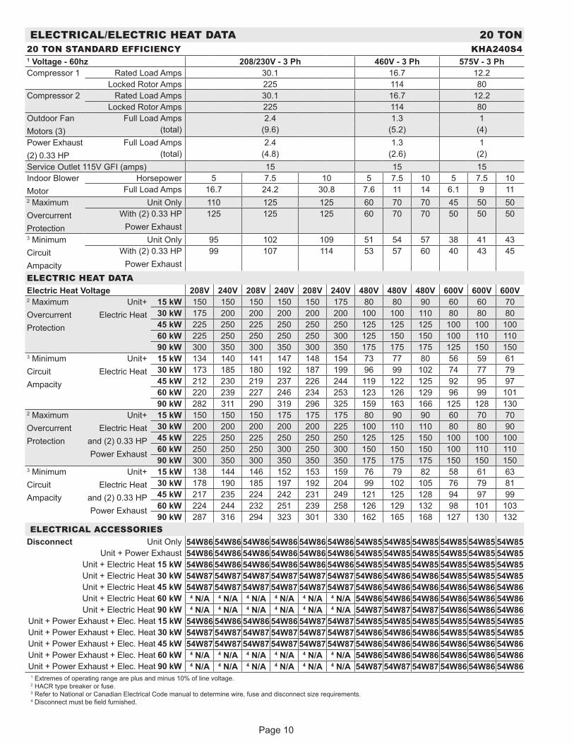
ELECTRICAL/ELECTRIC HEAT DATA 20 TON20 TON STANDARD EFFICIENCY KHA240S41 Voltage - 60hz 208/230V - 3 Ph 460V - 3 Ph 575V - 3 PhCompressor 1 Rated Load Amps 30.1 16.7 12.2
Locked Rotor Amps 225 114 80Compressor 2 Rated Load Amps 30.1 16.7 12.2
Locked Rotor Amps 225 114 80Outdoor FanMotors (3)
Full Load Amps 2.4 1.3 1(total) (9.6) (5.2) (4)
Power Exhaust(2) 0.33 HP
Full Load Amps 2.4 1.3 1(total) (4.8) (2.6) (2)
Service Outlet 115V GFI (amps) 15 15 15Indoor BlowerMotor
Horsepower 5 7.5 10 5 7.5 10 5 7.5 10Full Load Amps 16.7 24.2 30.8 7.6 11 14 6.1 9 11
2 MaximumOvercurrentProtection
Unit Only 110 125 125 60 70 70 45 50 50With (2) 0.33 HP
Power Exhaust125 125 125 60 70 70 50 50 50
3 MinimumCircuitAmpacity
Unit Only 95 102 109 51 54 57 38 41 43With (2) 0.33 HP
Power Exhaust99 107 114 53 57 60 40 43 45
ELECTRIC HEAT DATAElectric Heat Voltage 208V 240V 208V 240V 208V 240V 480V 480V 480V 600V 600V 600V2 MaximumOvercurrentProtection
Unit+Electric Heat
15 kW 150 150 150 150 150 175 80 80 90 60 60 7030 kW 175 200 200 200 200 200 100 100 110 80 80 8045 kW 225 250 225 250 250 250 125 125 125 100 100 10060 kW 225 250 250 250 250 300 125 150 150 100 110 11090 kW 300 350 300 350 300 350 175 175 175 125 150 150
3 MinimumCircuitAmpacity
Unit+Electric Heat
15 kW 134 140 141 147 148 154 73 77 80 56 59 6130 kW 173 185 180 192 187 199 96 99 102 74 77 7945 kW 212 230 219 237 226 244 119 122 125 92 95 9760 kW 220 239 227 246 234 253 123 126 129 96 99 10190 kW 282 311 290 319 296 325 159 163 166 125 128 130
2 MaximumOvercurrentProtection
Unit+Electric Heat
and (2) 0.33 HPPower Exhaust
15 kW 150 150 150 175 175 175 80 90 90 60 70 7030 kW 200 200 200 200 200 225 100 110 110 80 80 9045 kW 225 250 225 250 250 250 125 125 150 100 100 10060 kW 250 250 250 300 250 300 150 150 150 100 110 11090 kW 300 350 300 350 350 350 175 175 175 150 150 150
3 MinimumCircuitAmpacity
Unit+Electric Heat
and (2) 0.33 HPPower Exhaust
15 kW 138 144 146 152 153 159 76 79 82 58 61 6330 kW 178 190 185 197 192 204 99 102 105 76 79 8145 kW 217 235 224 242 231 249 121 125 128 94 97 9960 kW 224 244 232 251 239 258 126 129 132 98 101 10390 kW 287 316 294 323 301 330 162 165 168 127 130 132
ELECTRICAL ACCESSORIESDisconnect Unit Only 54W86 54W86 54W86 54W86 54W86 54W86 54W85 54W85 54W85 54W85 54W85 54W85
Unit + Power Exhaust 54W86 54W86 54W86 54W86 54W86 54W86 54W85 54W85 54W85 54W85 54W85 54W85Unit + Electric Heat 15 kW 54W86 54W86 54W86 54W86 54W86 54W86 54W85 54W85 54W85 54W85 54W85 54W85Unit + Electric Heat 30 kW 54W87 54W87 54W87 54W87 54W87 54W87 54W86 54W86 54W86 54W85 54W85 54W85Unit + Electric Heat 45 kW 54W87 54W87 54W87 54W87 54W87 54W87 54W86 54W86 54W86 54W86 54W86 54W86Unit + Electric Heat 60 kW 4 N/A 4 N/A 4 N/A 4 N/A 4 N/A 4 N/A 54W86 54W86 54W86 54W86 54W86 54W86Unit + Electric Heat 90 kW 4 N/A 4 N/A 4 N/A 4 N/A 4 N/A 4 N/A 54W87 54W87 54W87 54W86 54W86 54W86
Unit + Power Exhaust + Elec. Heat 15 kW 54W86 54W86 54W86 54W86 54W87 54W87 54W85 54W85 54W85 54W85 54W85 54W85Unit + Power Exhaust + Elec. Heat 30 kW 54W87 54W87 54W87 54W87 54W87 54W87 54W86 54W86 54W86 54W85 54W85 54W85Unit + Power Exhaust + Elec. Heat 45 kW 54W87 54W87 54W87 54W87 54W87 54W87 54W86 54W86 54W86 54W86 54W86 54W86Unit + Power Exhaust + Elec. Heat 60 kW 4 N/A 4 N/A 4 N/A 4 N/A 4 N/A 4 N/A 54W86 54W86 54W86 54W86 54W86 54W86Unit + Power Exhaust + Elec. Heat 90 kW 4 N/A 4 N/A 4 N/A 4 N/A 4 N/A 4 N/A 54W87 54W87 54W87 54W86 54W86 54W86
1 Extremes of operating range are plus and minus 10% of line voltage. 2 HACR type breaker or fuse. 3 Refer to National or Canadian Electrical Code manual to determine wire, fuse and disconnect size requirements. 4 Disconnect must be field furnished.
Page 11
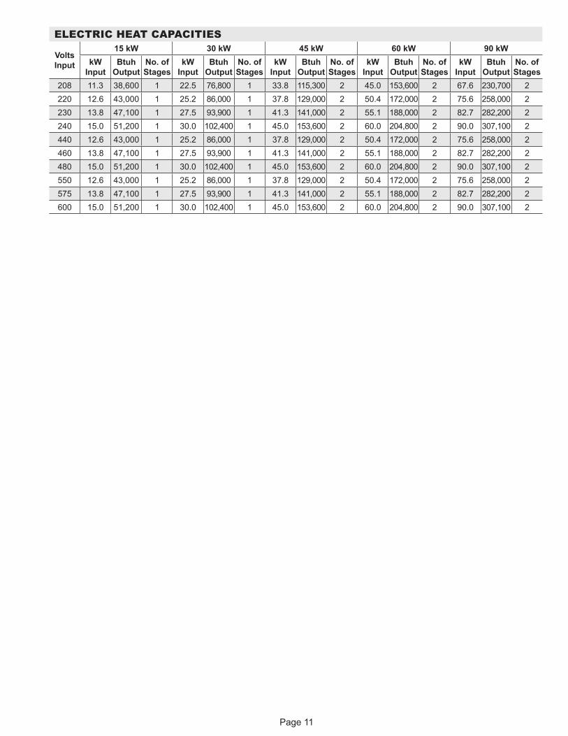
ELECTRIC HEAT CAPACITIES
Volts Input
15 kW 30 kW 45 kW 60 kW 90 kWkW
Input Btuh
Output No. of Stages
kW Input
Btuh Output
No. of Stages
kW Input
Btuh Output
No. of Stages
kW Input
Btuh Output
No. of Stages
kW Input
Btuh Output
No. of Stages
208 11.3 38,600 1 22.5 76,800 1 33.8 115,300 2 45.0 153,600 2 67.6 230,700 2 220 12.6 43,000 1 25.2 86,000 1 37.8 129,000 2 50.4 172,000 2 75.6 258,000 2 230 13.8 47,100 1 27.5 93,900 1 41.3 141,000 2 55.1 188,000 2 82.7 282,200 2 240 15.0 51,200 1 30.0 102,400 1 45.0 153,600 2 60.0 204,800 2 90.0 307,100 2 440 12.6 43,000 1 25.2 86,000 1 37.8 129,000 2 50.4 172,000 2 75.6 258,000 2 460 13.8 47,100 1 27.5 93,900 1 41.3 141,000 2 55.1 188,000 2 82.7 282,200 2 480 15.0 51,200 1 30.0 102,400 1 45.0 153,600 2 60.0 204,800 2 90.0 307,100 2 550 12.6 43,000 1 25.2 86,000 1 37.8 129,000 2 50.4 172,000 2 75.6 258,000 2 575 13.8 47,100 1 27.5 93,900 1 41.3 141,000 2 55.1 188,000 2 82.7 282,200 2 600 15.0 51,200 1 30.0 102,400 1 45.0 153,600 2 60.0 204,800 2 90.0 307,100 2

Page 12
KHA PARTS ARRANGEMENT
FIGURE 1
INDOOR COIL
OUTDOORFANS
OUTDOORCOIL
CONDENSATEDRAIN
FILTERS(SIX - 24 X 24 X 2”)
ECONOMIZER(OPTIONAL)
ELECTRIC HEAT(OPTIONAL)
COMPRESSORS
BLOWERS
FILTERDRIERS
FIGURE 2
KHA CONTROL BOX
CMC 1 CMC 2
T2
K9 K19
DL2 DL5
K65
T1 T18
GND
TB13 K3GND
S42 K1 K2K118
K58
K8
K216
C1 C2
C18 C19TB1
Electric Heat Control (Optional)
K10
K149
Page 13
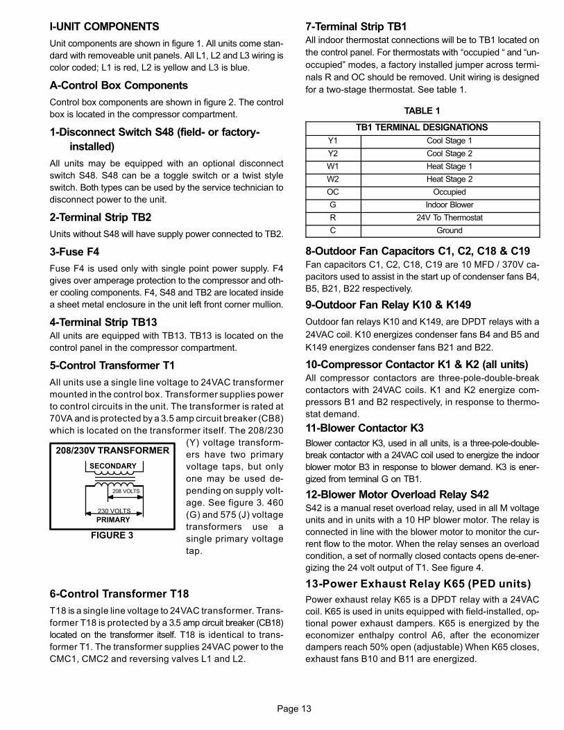
I-UNIT COMPONENTS
Unit components are shown in figure 1. All units come stan
dard with removeable unit panels. All L1, L2 and L3 wiring is
color coded; L1 is red, L2 is yellow and L3 is blue.
A-Control Box Components
Control box components are shown in figure 2. The control
box is located in the compressor compartment.
1-Disconnect Switch S48 (field- or factory-
installed)
All units may be equipped with an optional disconnect
switch S48. S48 can be a toggle switch or a twist style
switch. Both types can be used by the service technician to
disconnect power to the unit.
2-Terminal Strip TB2
Units without S48 will have supply power connected to TB2.
3-Fuse F4
Fuse F4 is used only with single point power supply. F4
gives over amperage protection to the compressor and oth
er cooling components. F4, S48 and TB2 are located inside
a sheet metal enclosure in the unit left front corner mullion.
4-Terminal Strip TB13All units are equipped with TB13. TB13 is located on the
control panel in the compressor compartment.
5-Control Transformer T1
All units use a single line voltage to 24VAC transformer
mounted in the control box. Transformer supplies power
to control circuits in the unit. The transformer is rated at
70VA and is protected by a 3.5 amp circuit breaker (CB8)
which is located on the transformer itself. The 208/230
(Y) voltage transform
ers have two primary
voltage taps, but only
one may be used de
pending on supply volt
age. See figure 3. 460
(G) and 575 (J) voltage
transformers use a
single primary voltage
tap.
6-Control Transformer T18
T18 is a single line voltage to 24VAC transformer. Trans
former T18 is protected by a 3.5 amp circuit breaker (CB18)
located on the transformer itself. T18 is identical to trans
former T1. The transformer supplies 24VAC power to the
CMC1, CMC2 and reversing valves L1 and L2.
7-Terminal Strip TB1All indoor thermostat connections will be to TB1 located on
the control panel. For thermostats with “occupied “ and “un
occupied” modes, a factory installed jumper across termi
nals R and OC should be removed. Unit wiring is designed
for a two-stage thermostat. See table 1.
TABLE 1
TB1 TERMINAL DESIGNATIONS
Y1 Cool Stage 1
Y2 Cool Stage 2
W1 Heat Stage 1
W2 Heat Stage 2
OC Occupied
G Indoor Blower
R 24V To Thermostat
C Ground
8-Outdoor Fan Capacitors C1, C2, C18 & C19Fan capacitors C1, C2, C18, C19 are 10 MFD / 370V ca
pacitors used to assist in the start up of condenser fans B4,
B5, B21, B22 respectively.
9-Outdoor Fan Relay K10 & K149
Outdoor fan relays K10 and K149, are DPDT relays with a
24VAC coil. K10 energizes condenser fans B4 and B5 and
K149 energizes condenser fans B21 and B22.
10-Compressor Contactor K1 & K2 (all units)All compressor contactors are three‐pole‐double‐break
contactors with 24VAC coils. K1 and K2 energize com
pressors B1 and B2 respectively, in response to thermo
stat demand.
11-Blower Contactor K3
Blower contactor K3, used in all units, is a three‐pole‐double‐
break contactor with a 24VAC coil used to energize the indoor
blower motor B3 in response to blower demand. K3 is ener
gized from terminal G on TB1.
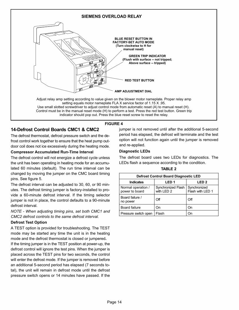
12-Blower Motor Overload Relay S42S42 is a manual reset overload relay, used in all M voltage
units and in units with a 10 HP blower motor. The relay is
connected in line with the blower motor to monitor the cur
rent flow to the motor. When the relay senses an overload
condition, a set of normally closed contacts opens de-ener
gizing the 24 volt output of T1. See figure 4.
13-Power Exhaust Relay K65 (PED units)
Power exhaust relay K65 is a DPDT relay with a 24VAC
coil. K65 is used in units equipped with field-installed, op
tional power exhaust dampers. K65 is energized by the
economizer enthalpy control A6, after the economizer
dampers reach 50% open (adjustable) When K65 closes,
exhaust fans B10 and B11 are energized.
FIGURE 3
230 VOLTS
208 VOLTS
PRIMARY
SECONDARY
208/230V TRANSFORMER
Page 14
SIEMENS OVERLOAD RELAY
Adjust relay amp setting according to value given on the blower motor nameplate. Proper relay ampsetting equals motor nameplate FLA X service factor of 1.15 X .95.
Use small slotted screwdriver to adjust control mode from automatic reset (A) to manual reset (H). Control must be in the manual reset mode (H) to perform a test. Press the red test button. Green trip
indicator should pop out. Press the blue reset screw to reset the relay.
BLUE RESET BUTTON INFACTORY‐SET AUTO MODE
(Turn clockwise to H formanual reset)
GREEN TRIP INDICATOR(Flush with surface -- not tripped;
Above surface -- tripped)
AMP ADJUSTMENT DIAL
RED TEST BUTTON
FIGURE 4
14-Defrost Control Boards CMC1 & CMC2
The defrost thermostat, defrost pressure switch and the de
frost control work together to ensure that the heat pump out
door coil does not ice excessively during the heating mode.
Compressor Accumulated Run-Time Interval
The defrost control will not energize a defrost cycle unless
the unit has been operating in heating mode for an accumu
lated 60 minutes (default). The run time interval can be
changed by moving the jumper on the CMC board timing
pins. See figure 5.
The defrost interval can be adjusted to 30, 60, or 90 min
utes. The defrost timing jumper is factory-installed to pro
vide a 60-minute defrost interval. If the timing selector
jumper is not in place, the control defaults to a 90-minute
defrost interval.
NOTE - When adjusting timing pins, set both CMC1 and
CMC2 defrost controls to the same defrost interval.
Defrost Test Option
A TEST option is provided for troubleshooting. The TEST
mode may be started any time the unit is in the heating
mode and the defrost thermostat is closed or jumpered.
If the timing jumper is in the TEST position at power‐up, the
defrost control will ignore the test pins. When the jumper is
placed across the TEST pins for two seconds, the control
will enter the defrost mode. If the jumper is removed before
an additional 5-second period has elapsed (7 seconds to
tal), the unit will remain in defrost mode until the defrost
pressure switch opens or 14 minutes have passed. If the
jumper is not removed until after the additional 5-second
period has elapsed, the defrost will terminate and the test
option will not function again until the jumper is removed
and re-applied.
Diagnostic LEDs
The defrost board uses two LEDs for diagnostics. The
LEDs flash a sequence according to the condition.
TABLE 2
Defrost Control Board Diagnostic LED
Indicates LED 1 LED 2
Normal operation / power to board
Synchronized Flashwith LED 2
SynchronizedFlash with LED 1
Board failure /no power
Off Off
Board failure On On
Pressure switch open Flash On

Page 15
DEFROST CONTROL BOARDCMC1 AND CMC2
TIMINGJUMPER
FIGURE 5
DIAGNOSTICLEDS
Page 16
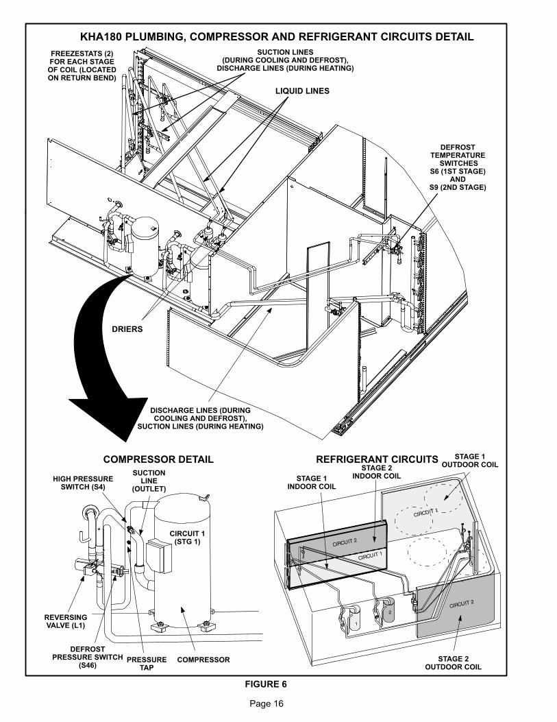
KHA180 PLUMBING, COMPRESSOR AND REFRIGERANT CIRCUITS DETAIL
FIGURE 6
LIQUID LINES
FREEZESTATS (2)FOR EACH STAGEOF COIL (LOCATEDON RETURN BEND)
COMPRESSOR
CIRCUIT 1(STG 1)
REVERSINGVALVE (L1)
SUCTIONLINE
(OUTLET)
DEFROSTPRESSURE SWITCH
(S46)
HIGH PRESSURESWITCH (S4)
PRESSURETAP
DISCHARGE LINES (DURINGCOOLING AND DEFROST),
SUCTION LINES (DURING HEATING)
COMPRESSOR DETAIL REFRIGERANT CIRCUITS STAGE 1OUTDOOR COIL
STAGE 2OUTDOOR COIL
STAGE 1INDOOR COIL
STAGE 2INDOOR COIL
DEFROSTTEMPERATURE
SWITCHESS6 (1ST STAGE)
ANDS9 (2ND STAGE)
SUCTION LINES(DURING COOLING AND DEFROST),
DISCHARGE LINES (DURING HEATING)
DRIERS
Page 17
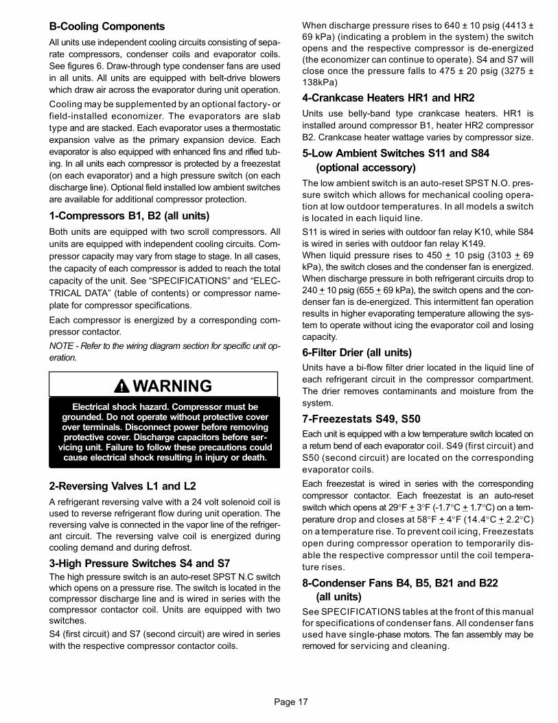
B-Cooling Components
All units use independent cooling circuits consisting of sepa
rate compressors, condenser coils and evaporator coils.
See figures 6. Draw-through type condenser fans are used
in all units. All units are equipped with belt‐drive blowers
which draw air across the evaporator during unit operation.
Cooling may be supplemented by an optional factory- or
field‐installed economizer. The evaporators are slab
type and are stacked. Each evaporator uses a thermostatic
expansion valve as the primary expansion device. Each
evaporator is also equipped with enhanced fins and rifled tub
ing. In all units each compressor is protected by a freezestat
(on each evaporator) and a high pressure switch (on each
discharge line). Optional field installed low ambient switches
are available for additional compressor protection.
1-Compressors B1, B2 (all units)
Both units are equipped with two scroll compressors. All
units are equipped with independent cooling circuits. Com
pressor capacity may vary from stage to stage. In all cases,
the capacity of each compressor is added to reach the total
capacity of the unit. See “SPECIFICATIONS” and “ELEC
TRICAL DATA” (table of contents) or compressor name
plate for compressor specifications.
Each compressor is energized by a corresponding com
pressor contactor.
NOTE - Refer to the wiring diagram section for specific unit op
eration.
WARNINGElectrical shock hazard. Compressor must be
grounded. Do not operate without protective coverover terminals. Disconnect power before removingprotective cover. Discharge capacitors before ser
vicing unit. Failure to follow these precautions couldcause electrical shock resulting in injury or death.
2-Reversing Valves L1 and L2
A refrigerant reversing valve with a 24 volt solenoid coil is
used to reverse refrigerant flow during unit operation. The
reversing valve is connected in the vapor line of the refriger
ant circuit. The reversing valve coil is energized during
cooling demand and during defrost.
3-High Pressure Switches S4 and S7
The high pressure switch is an auto-reset SPST N.C switch
which opens on a pressure rise. The switch is located in the
compressor discharge line and is wired in series with the
compressor contactor coil. Units are equipped with two
switches.
S4 (first circuit) and S7 (second circuit) are wired in series
with the respective compressor contactor coils.
When discharge pressure rises to 640 ± 10 psig (4413 ±
69 kPa) (indicating a problem in the system) the switch
opens and the respective compressor is de-energized
(the economizer can continue to operate). S4 and S7 will
close once the pressure falls to 475 ± 20 psig (3275 ±
138kPa)
4-Crankcase Heaters HR1 and HR2
Units use belly‐band type crankcase heaters. HR1 is
installed around compressor B1, heater HR2 compressor
B2. Crankcase heater wattage varies by compressor size.
5-Low Ambient Switches S11 and S84
(optional accessory)
The low ambient switch is an auto‐reset SPST N.O. pres
sure switch which allows for mechanical cooling opera
tion at low outdoor temperatures. In all models a switch
is located in each liquid line.
S11 is wired in series with outdoor fan relay K10, while S84
is wired in series with outdoor fan relay K149.
When liquid pressure rises to 450 + 10 psig (3103 + 69
kPa), the switch closes and the condenser fan is energized.
When discharge pressure in both refrigerant circuits drop to
240 + 10 psig (655 + 69 kPa), the switch opens and the con
denser fan is de-energized. This intermittent fan operation
results in higher evaporating temperature allowing the sys
tem to operate without icing the evaporator coil and losing
capacity.
6-Filter Drier (all units)
Units have a bi-flow filter drier located in the liquid line of
each refrigerant circuit in the compressor compartment.
The drier removes contaminants and moisture from the
system.
7-Freezestats S49, S50
Each unit is equipped with a low temperature switch located on
a return bend of each evaporator coil. S49 (first circuit) and
S50 (second circuit) are located on the corresponding
evaporator coils.
Each freezestat is wired in series with the corresponding
compressor contactor. Each freezestat is an auto-reset
switch which opens at 29°F + 3°F (‐1.7°C + 1.7°C) on a tem
perature drop and closes at 58°F + 4°F (14.4°C + 2.2°C)
on a temperature rise. To prevent coil icing, Freezestats
open during compressor operation to temporarily dis
able the respective compressor until the coil tempera
ture rises.
8-Condenser Fans B4, B5, B21 and B22
(all units)
See SPECIFICATIONS tables at the front of this manual
for specifications of condenser fans. All condenser fans
used have single-phase motors. The fan assembly may be
removed for servicing and cleaning.
Page 18
9-Defrost Components and Operation
a-Defrost Pressure Switch S46 and S104
The defrost pressure switches (S46 and S104) are auto‐
reset SPST N.C. pressure switches which open on a
pressure rise. All units are equipped with these
switches. The switches are located on the vapor line during
heating cycle (discharge line during cooling and defrost
cycle).
S46 (refrigeration circuit one) is wired to the main control board
CMC1. S104 (refrigeration circuit two) is wired to the heat
pump control board CMC2.
When discharge pressure reaches 450 + 10 psig (3103 ±
69 kPa) (indicating defrost is completed) the switch opens.
The switch automatically resets when pressure in the vapor
line drops to 300 + 10 psig (2068 ± 69 kPa).
b-Defrost Thermostat Switches S6 and S9
(all units)
Defrost thermostat switches S6 (refrigeration circuit one) and
S9 (refrigeration circuit two) are S.P.S.T. N.O. contacts which
close on a temperature fall (initiating defrost). The switches
are located on each of the expansion valve distributor
assemblies at the inlet to the outdoor coil. The switches
monitor the outdoor coil suction temperature to deter
mine when defrost is needed. When the outdoor coil suc
tion temperature falls to 35°F + 4°F (1.7°C + 2.2°C) the
switch closes (initiating defrost after minimum run time of
30, 60, or 90 minutes). When the temperature rises to 60°F+ 5°F (15.6°C + 2.8°C) the switch opens.
DEFROST OPERATION
Defrost operation of each of the two refrigeration circuits
are controlled independently with separate timers, thermo
stats (S6 and S9) and pressure switches (S46 and S104).
During heating operation when outdoor coil temperature
drops to 35 ± 4 °, the defrost thermostat S6 or S9 closes
initiating defrost.
When defrost begins, the reversing valve (L1 or L2) for the
circuit in defrost mode is energized. Supplemental electric
heat is then energized.
When L1 energizes, N.C. K58-1 contacts open de-energiz
ing outdoor fan relay K10, followed by outdoor fan B4.
When L2 energizes, N.C. K118-1 contacts open de-ener
gizing outdoor fan relay K149, followed by outdoor fan B5.
Defrost of a circuit terminates when the pressure switch for
the circuit (S46 or S104) opens or when 15 minutes elapse.
Defrost does not terminate when thermostat demand
ends.
C-Blower Compartment
The blower compartment in is located between the evapo
rator coil and the compressor / control section on the oppo
site side of the condenser coil. The blower assembly is ac
cessed by removing the screws on either side of the sliding
base. The base pulls out as shown in figure 7.
1-Blower Wheels
Units have two 15 in. x 15 in. (381 mm x 381 mm) blower
wheels. Both wheels are driven by one motor mounted on a
single shaft. Shaft bearings are equipped with grease ports for
service.
2-Indoor Blower Motor B3
All units use three‐phase single‐speed blower motors.
CFM adjustments are made by adjusting the motor pulley
(sheave). Motors are equipped with sealed ball bearings.
All motor specifications are listed in the SPECIFI
CATIONS (table of contents) in the front of this manual.
Units may be equipped with motors manufactured by vari
ous manufacturers, therefore electrical FLA and LRA
specifications will vary. See unit rating plate for informa
tion specific to your unit.
OPERATION / ADJUSTMENT
Blower Operation
Initiate blower demand at thermostat according to instruc
tions provided with thermostat. Unit will cycle on thermostat
demand. The following steps apply to applications using a
typical elector-mechanical thermostat.
1- Blower operation is manually set at the thermostat sub
base fan switch. With fan switch in ON position, blow
ers will operate continuously.
2- With fan switch in AUTO position, the blowers will cycle
with demand. Blowers and entire unit will be off when
system switch is in OFF position.
Blower Access
The blower assembly is secured to a sliding base which al
lows the entire assembly to be pulled out of the unit. See
figure 7.
1- Remove the clamp which secures the blower wiring to
the blower motor base.
2- Remove and retain screws on either side of sliding
base. Pull base toward outside of unit. When pulling the
base out further than 12” (305mm), disconnect wiring
to K3 blower contactor T1, T2 and T3. Pull wiring to
ward blower to allow enough slack to slide the base out
further.

Page 19
FIGURE 7
BLOWER ASSEMBLY
TO INCREASE BELT TENSION
1-Loosen four screws securing blower motor tosliding base.
2-Turn adjusting screw to the left, or counterclockwise, to move the motor downward andtighten the belt.
3-Tighten four screws.
TO INCREASE CFMLOOSEN ALLEN SCREW &
TURN PULLEY CLOCKWISE
TO DECREASE CFMTURN PULLEY
COUNTERCLOCKWISE
BLOWERWHEEL
BLOWERMOTOR
PULLEY
BLOWERASSEMBLY
SLIDING BASE
BELT TENSIONADJUSTING
SCREW
LOOSEN (4) SCREWS ONMOTOR BASE TO ALLOW
MOTOR TO MOVE.
REMOVE SCREWS TOSLIDE BLOWER
ASSEMBLY OUT OF UNITPULLEY
MOTOR ALLENSCREW
SIDE VIEW
3- Slide base back into original position when finished
servicing. Replace the clamp and blower wiring in the
previous location on the blower motor base. Reconnect
wiring to K3 if it was disconnected.
4- Replace retained screws on either side of the sliding
base.
Determining Unit Air Volume
1- The following measurements must be made with a dry in
door coil. Run blower without cooling demand. Air filters
must be in place when measurements are taken.
2- With all access panels in place, measure static pres
sure external to unit (from supply to return).
3- Measure the indoor blower wheel RPM.
4- Refer to blower tables in BLOWER DATA (table of con
tents) in the front of this manual. Use static pressure and
RPM readings to determine unit air volume.
5- The RPM can be adjusted at the motor pulley. Loosen
Allen screw and turn adjustable pulley clockwise to in
crease RPM. Turn counterclockwise to decrease RPM.
See figure 7. Tighten Allen screw after adjustment.
Blower Belt Adjustment
Maximum life and wear can be obtained from belts only if
proper pulley alignment and belt tension are main
tained. Tension new belts after a 24-48 hour period of op
eration. This will allow belt to stretch and seat grooves.
Make sure blower and motor pulley are aligned as shown in
figure 8.
FIGURE 8
PULLEY ALIGNMENT
BELTBLOWERPULLEY
MOTORPULLEY
NOT ALIGNED
ALIGNED
1- Loosen four bolts securing motor base to mounting
frame. See figure 7.
2- To relieve belt tension -
Turn adjusting bolt to the right, or clockwise, to move
the motor upward and loosen the belt. This decreases
the distance between the blower motor pulley and the
blower housing pulley.
To increase belt tension -
Turn the adjusting bolt to the left, or counterclockwise
to increase belt tension. This increases the distance
between motor pulley and blower housing pulley (mo
tor moves downward and tightens belt).
3- Tighten four bolts securing motor base to mounting
frame.
Page 20
IMPORTANT - Align top edges of blower motor base and
mounting frame base parallel before tightening bolts on the
both sides of base. Motor shaft and blower shaft must be
parallel.
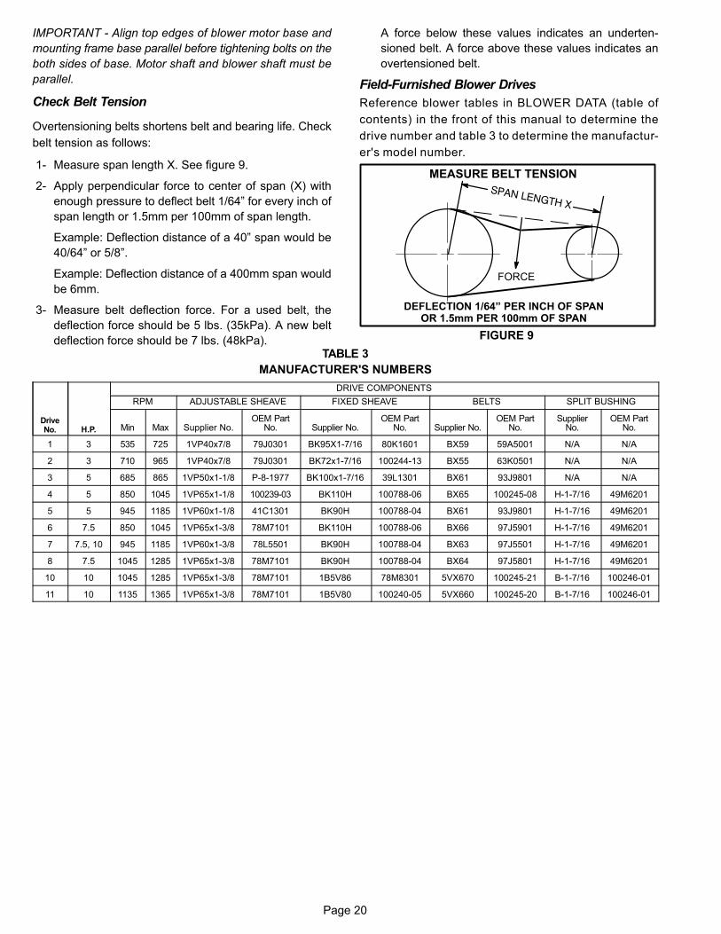
Check Belt Tension
Overtensioning belts shortens belt and bearing life. Check
belt tension as follows:
1- Measure span length X. See figure 9.
2- Apply perpendicular force to center of span (X) with
enough pressure to deflect belt 1/64” for every inch of
span length or 1.5mm per 100mm of span length.
Example: Deflection distance of a 40” span would be
40/64” or 5/8”.
Example: Deflection distance of a 400mm span would
be 6mm.
3- Measure belt deflection force. For a used belt, the
deflection force should be 5 lbs. (35kPa). A new belt
deflection force should be 7 lbs. (48kPa).
A force below these values indicates an underten
sioned belt. A force above these values indicates an
overtensioned belt.
Field-Furnished Blower Drives
Reference blower tables in BLOWER DATA (table of
contents) in the front of this manual to determine the
drive number and table 3 to determine the manufactur
er's model number.
MEASURE BELT TENSION
FIGURE 9
DEFLECTION 1/64” PER INCH OF SPANOR 1.5mm PER 100mm OF SPAN
FORCE
TABLE 3
MANUFACTURER'S NUMBERS
DriveNo. H.P.
DRIVE COMPONENTS
RPM ADJUSTABLE SHEAVE FIXED SHEAVE BELTS SPLIT BUSHING
Min Max Supplier No.OEM Part
No. Supplier No.OEM Part
No. Supplier No.OEM Part
No.Supplier
No.OEM Part
No.
1 3 535 725 1VP40x7/8 79J0301 BK95X1-7/16 80K1601 BX59 59A5001 N/A N/A
2 3 710 965 1VP40x7/8 79J0301 BK72x1‐7/16 100244-13 BX55 63K0501 N/A N/A
3 5 685 865 1VP50x1-1/8 P-8-1977 BK100x1‐7/16 39L1301 BX61 93J9801 N/A N/A
4 5 850 1045 1VP65x1-1/8 100239-03 BK110H 100788-06 BX65 100245-08 H-1-7/16 49M6201
5 5 945 1185 1VP60x1-1/8 41C1301 BK90H 100788-04 BX61 93J9801 H-1-7/16 49M6201
6 7.5 850 1045 1VP65x1-3/8 78M7101 BK110H 100788-06 BX66 97J5901 H-1-7/16 49M6201
7 7.5, 10 945 1185 1VP60x1-3/8 78L5501 BK90H 100788-04 BX63 97J5501 H-1-7/16 49M6201
8 7.5 1045 1285 1VP65x1-3/8 78M7101 BK90H 100788-04 BX64 97J5801 H-1-7/16 49M6201
10 10 1045 1285 1VP65x1-3/8 78M7101 1B5V86 78M8301 5VX670 100245-21 B-1-7/16 100246-01
11 10 1135 1365 1VP65x1-3/8 78M7101 1B5V80 100240-05 5VX660 100245-20 B-1-7/16 100246-01

Page 21
D-Optional Electric Heat Components
See ELECTRICAL / ELECTRIC HEAT (table of contents)
for possible KHA to C1EH match-ups and electrical ratings.
All electric heat sections consist of electric heating ele
ments exposed directly to the air stream. See figure 1. Two
electric heat sections (first section and second section)
are used in all 15kW through 90kW heaters. Multiple‐
stage elements are sequenced on and off in response to
thermostat demand. C1EH parts arrangement is shown in
figures 11 and 12.
Control Box ComponentsThe main control box (see figure 2) houses some electric
heat components and the electric heat control “hat” section
(figure 10).
Electric Heat Hat Section (Figure 10)
1-Electric Heat Relay K9
All units equipped with electric heat use an electric heat
relay K9. K9 is a N.O. DPDT pilot relay intended to electri
cally isolate the unit's 24V circuit from the electric heat as
sembly 24V circuit. K9 is energized by W1 TB1. K9-1
closes, enabling T2 to energize the electric heat.
2-Electric Heat Relay K19
All units equipped with electric heat use an electric heat
relay K19. K19 is a N.O. SPDT pilot relay intended to elec
trically isolate the unit's 24V circuit from the electric heat as
sembly 24V circuit. K19 is energized by TB1 (once K9 is en
ergized). K19-1 closes, enabling T2 to energize the
remaining electric heat.
3-Time Delay DL2
DL2 is a solid state timer used in all electric heat units.
DL2 staggers the energizing of the first (W1) and second
(W2) stage heating elements by providing a timed inter
val. When the timer is de-energizing, the contacts are
delayed 1 second before opening.
4-Time Delay DL5
Time delay DL5 is identical to DL2. DL5 further staggers
the (W2) second stage heating elements by providing a
timed interval between the energizing of the elements
activated by DL2 and elements activated by DL5.
ELECTRIC HEAT CONTROL (HAT) ASSEMBLY
FIGURE 10
TRANSFORMERT2
TIME DELAYDL2, DL5
RELAYK9, K19
FIGURE 11
C1EH 15, 30, 45, 60 and 90 KW ELECTRIC HEAT SECTION PARTS ARRANGEMENT
PRIMARY ELECTRICHEAT LIMIT
S15(1ST SECTION)S107(2nd SECTION)
HEATING ELEMENTSHE1 - HE14
CONTROL WIREHARNESS
ELECTRIC HEATVESTIBULE

Page 22
Figure 12
ELECTRIC HEAT VESTIBULE PARTS ARRANGEMENT
TERMINAL STRIP(TB3)
FIRST STAGE ELECTRICHEAT CONTACTOR K15
SECOND STAGE ELECTRICHEAT CONTACTOR K16
FIRST HEAT SECTION (LEFT SIDE)
SECOND HEAT SECTION (RIGHT SIDE)
FUSE F3F3 ‐ 1 FUSE F3
F3 ‐ 2FUSE F3
F3 ‐ 3
FUSE F3F3 ‐ 4
TERMINAL STRIP(TB3)
FIRST STAGE ELECTRICHEAT CONTACTOR K17
SECOND STAGE ELECTRICHEAT CONTACTOR K18
FUSE F3F3 ‐ 5 FUSE F3
F3 ‐ 6FUSE F3
F3 ‐ 7
FUSE F3F3 ‐ 8

Page 23
5-Electric Heat Transformer T2
All units equipped with electric heat use a single line volt
age to 24VAC transformer mounted in the electric heat
control hat section in the control box. The transformer
supplies power to all electric heat controls (contactors
and coils). The transformer is rated at 70VA and is pro
tected by a 3.5 amp circuit breaker CB13 located on the
body of T2. The 208/230 (Y) voltage transformers use
two primary voltage taps as shown in figure 3. Transform
er T2 is identical to T1.
Electric Heat Sections
6-Contactors K15, K16, K17 and K18
Contactors K15, K16, K17 and K18 are all three‐pole
double‐break contactors located on the electric heat vesti
bule. K15 and K16 are located on the first electric heat sec
tion, while K17 and K18 are located on the second electric
heat section. However, in the 15 and 30kW heaters, the first
section houses all contactors and fuses. All contactors are
equipped with a 24VAC coil. The coils in the K15, K16, K17
and K18 contactors are energized by the main panel
A45. Contactors K15 and K17 energize the first stage
heating elements, while K16 and K18 energize the second
stage heating elements.
7-Fuse F3
Fuse F3 are housed in a fuse block which holds three fuses.
Each F3 fuse is connected in series with each leg of electric
heat. Figure 12 and table 4 show the fuses used with each
electric heat section. For simplicity, the service manual la
bels the fuses F3 - 1 through F3 - 8.
8-Terminal Strip TB3
Electric heat line voltage connections are made to terminal
strip TB3 (or a fuse block on some models) located in the up
per left corner of the electric heat vestibule.
9-High Temperature Limits S15 and S107
(Primary)
S15 and S107 are SPST N.C. auto‐reset thermostats lo
cated on the back panel of the electric heat section below
the heating elements. S15 is the high temperature limit for
the first electric heat section, while S107 is the high temper
ature limit for the second electric heat section. Both thermo
stats are identical and are wired in series with the first stage
contactor coil. When either S15 or S107 opens, indicating a
problem in the system, contactor K15 is de‐energized.
When K15 is de‐energized, first stage and all subsequent
stages of heat are de‐energized. The thermostats used on
C1EH360‐45‐1 Y/G/J are factory set to open at 200�F +
5�F (93.3�C + 2.8�C) on a temperature rise and automati
cally reset at 160�F + 6�F (71.1�C + 3.3�C) on a tempera
ture fall. All other electric heat section thermostats are fac
tory set to open at 170�F + 5�F (76.7�C + 2.8�C) on a
temperature rise and automatically reset at 130�F + 6�F
(54.4�C + 3.3�C) on a temperature fall. The thermostats
are not adjustable.
10-Heating Elements HE1 through HE14
Heating elements are composed of helix wound bare nich
rome wire exposed directly to the air stream. Three ele
ments are connected in a three‐phase arrangement. The
elements in 208/230V units are connected in a “Delta” ar
rangement. Elements in 460 and 575V units are connected
in “Wye” arrangement. Each stage is energized indepen
dently by the corresponding contactors located on the elec
tric heat vestibule panel. Once energized, heat transfer is
instantaneous. High temperature protection is provided by
primary and redundant high temperature limits and over
current protection is provided by fuses.
TABLE 4
KHA180/240 ELECTRIC HEAT SECTION FUSE RATING
C1EH QUANTITY
& SIZE
VOLTAGES
FUSE (3 each)
F3 - 1 F3 - 2 F3 - 3 F3 - 4 F3 - 5 F3 - 6 F3 - 7 F3 - 8
(1) 240-7.5 &(1) 240S-7.5(15 kW Total)
208/230V 50 Amp 250V ----- ----- ----- ----- ----- ----- -----
460V 25 Amp 600V ----- ----- ----- ----- ----- ----- -----
575V 20 Amp 600V ----- ----- ----- ----- ----- ----- -----
(1) 360-15 &(1) 360S-15
(30 kW Total)or
(1) 156-15 &(1) 156S-15
208/230V 60 Amp 250V 60 Amp 250V ----- ----- ----- ----- ----- -----
460V 50 Amp 600V ----- ----- ----- ----- ----- ----- -----
575V 40 Amp 600V ----- ----- ----- ----- ----- ----- -----
(2) 360-22.5(45 kW Total)
or(2) 156-22.5
208/230V 50 Amp 250V ----- ----- 25 Amp 250V 50 Amp 250V ----- ----- 25 Amp 250V
460V 25 Amp 600V ----- ----- 15 Amp 600V 25 Amp 600V ----- ----- 15 Amp 600V
575V 20 Amp 600V ----- ----- 10 Amp 600V 20 Amp 600V ----- ----- 10 Amp 600V
(2) 150-30(60 kW Total)
or(2) 156-30
208/230V 50 Amp 250V ----- ----- 50 Amp 250V 50 Amp 250V ----- ----- 50 Amp 250V
460V 25 Amp 600V ----- ----- 25 Amp 600V 25 Amp 600V ----- ----- 25 Amp 600V
575V 20 Amp 600V ----- ----- 20 Amp 600V 20 Amp 600V ----- ----- 20 Amp 600V
(2) 360-45(90 kW Total)
208/230V 50 Amp 250V ----- 60 Amp 250V 60 Amp 250V 50 Amp 250V -----60 Amp250V 60 Amp 250V
460V 25 Amp 600V ----- ----- 50 Amp 600V 25 Amp 600V ----- ----- 50 Amp 600V
575V 20 Amp 600V ----- ----- 40 Amp 600V 20 Amp 600V ----- ----- 40 Amp 600V
Page 24
II-PLACEMENT AND INSTALLATION
Make sure the unit is installed in accordance with the
installation instructions and all applicable codes. See
accessories section for conditions requiring use of the
optional roof mounting frame.
III-STARTUP - OPERATION
Refer to startup directions and to the unit wiring diagram
when servicing. See unit nameplate for minimum circuit
ampacity and maximum fuse size.
A-Preliminary and Seasonal Checks
1- Make sure the unit is installed in accordance with the
installation instructions and applicable codes.
2- Inspect all electrical wiring, both field and factory installed
for loose connections. Tighten as required. Refer to unit
diagram located on inside of unit control box cover.
3- Check to ensure that refrigerant lines are in good
condition and do not rub against the cabinet or other
refrigerant lines.
4- Check voltage at the disconnect switch (if applicable)
or TB2. Voltage must be within the range listed on the
nameplate. If not, consult the power company and
have the voltage corrected before starting the unit.
5- Recheck voltage and amp draw with unit running. If
voltage is not within range listed on unit nameplate,
stop unit and consult power company. Refer to unit
nameplate for maximum rated load amps.
6- Inspect and adjust blower belt (see section on Blower
Compartment - Blower Belt Adjustment).
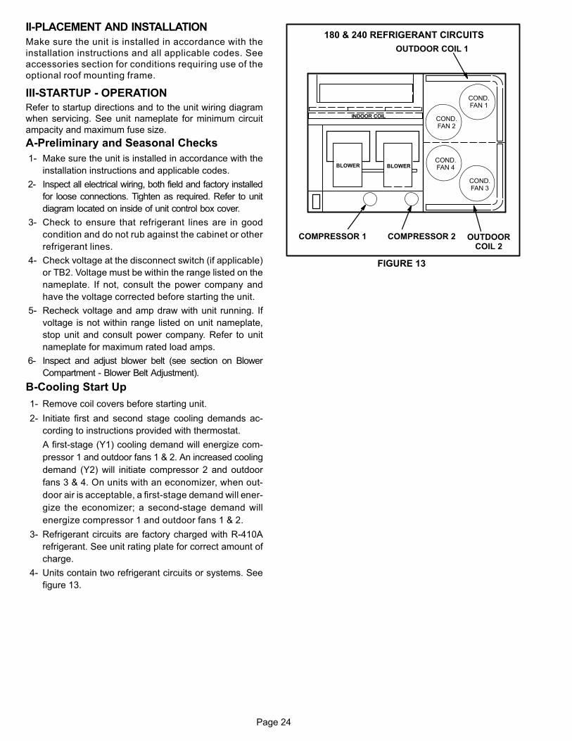
B-Cooling Start Up
1- Remove coil covers before starting unit.
2- Initiate first and second stage cooling demands ac
cording to instructions provided with thermostat.
A first-stage (Y1) cooling demand will energize com
pressor 1 and outdoor fans 1 & 2. An increased cooling
demand (Y2) will initiate compressor 2 and outdoor
fans 3 & 4. On units with an economizer, when out
door air is acceptable, a first-stage demand will ener
gize the economizer; a second-stage demand will
energize compressor 1 and outdoor fans 1 & 2.
3- Refrigerant circuits are factory charged with R-410A
refrigerant. See unit rating plate for correct amount of
charge.
4- Units contain two refrigerant circuits or systems. See
figure 13.
FIGURE 13
BLOWER
INDOOR COIL
BLOWER
180 & 240 REFRIGERANT CIRCUITS
COMPRESSOR 1 COMPRESSOR 2 OUTDOORCOIL 2
COND.FAN 1
COND.FAN 2
COND.FAN 4
COND.FAN 3
OUTDOOR COIL 1

Page 25
IV-CHARGING
WARNINGRefrigerant can be harmful if it is inhaled. Refrigerantmust be used and recovered responsibly.
Failure to follow this warning may result in personal injury or death.
WARNING - Do not exceed nameplate charge underany condition.
This unit is factory-charged and should require no further
adjustment. If the system requires additional refrigerant, re
claim the charge, evacuate the system and add required
nameplate charge.
NOTE - System charging is not recommended below 60°F
(15°C). In temperatures below 60°F (15°C) , the charge
must be weighed into the system.
If weighing facilities are not available, or to check the
charge, use the following procedure:
1- Attach gauge manifolds and operate unit in cooling
mode with economizer disabled until system stabilizes
(approximately five minutes). Make sure outdoor air
dampers are closed.
2- Check each system separately with all stages operat
ing.
3- Use a thermometer to accurately measure the outdoor
ambient temperature.
4- Apply the outdoor temperature to tables 5 through 6 to
determine normal operating pressures. Pressures are
listed for sea level applications at 80°F dry bulb and 67°F wet
bulb return air.
5- Compare the normal operating pressures to the pres
sures obtained from the gauges. Minor variations in
these pressures may be expected due to differences in
installations. Significant differences could mean that
the system is not properly charged or that a problem
exists with some component in the system. Correct
any system problems before proceeding.
6- If discharge pressure is high, remove refrigerant from
the system. If discharge pressure is low, add refrigerant
to the system.
� Add or remove charge in increments.
� Allow the system to stabilize each time refrigerant
is added or removed.
7- Use the following approach method along with the nor
mal operating pressures to confirm readings.
TABLE 5KHA180 NORMAL OPERATING PRESSURES
OutdoorCoil Entering
Air Temp
Circuit 1 Circuit 2
Dis. +10psig
Suc. +5psig
Dis. +10psig
Suc. +5psig
65�F 270 138 270 135
75�F 312 139 312 135
85�F 356 142 356 136
95�F 403 144 404 138
105�F 455 147 458 140
115�F 512 147 515 145
TABLE 6KHA240 NORMAL OPERATING PRESSURES
OutdoorCoil Entering
Air Temp
Circuit 1 Circuit 2
Dis. +10psig
Suc. +5psig
Dis. +10psig
Suc. +5psig
65�F 275 135 278 135
75�F 315 138 318 136
85�F 359 140 364 138
95�F 407 142 413 140
105�F 457 144 466 141
115�F 517 146 527 145
C-Charge Verification - Approach Method - AHRI Testing
1- Using the same thermometer, compare liquid tempera
ture to outdoor ambient temperature.
Approach Temperature = Liquid temperature (at con
denser outlet) minus ambient temperature.
2- Approach temperatures should match values in table
7. An approach temperature greater than this value indi
cates an undercharge. An approach temperature less
than this value indicates an overcharge.
3- Do not use the approach method if system pressures
do not match pressures in tables 5 through 6. The ap
proach method is not valid for grossly over or under
charged systems.
TABLE 7APPROACH TEMPERATURES
Unit
Liquid Temp. Minus Ambient Temp.
1st Stage 2nd Stage
180 & 24012°F + 1
(6.7°C + 0.5)12°F + 1
(6.7°C + 0.5)
Page 26
V- SYSTEMS SERVICE CHECKS
A-Cooling System Service Checks
Units are factory charged and require no further adjustment;
however, charge should be checked periodically using the ap
proach method. The approach method compares actual liquid
temperature with the outdoor ambient temperature. See sec
tion IV- CHARGING.
NOTE - When unit is properly charged discharge line pres
sures should approximate those in tables 5 through 6.
VI-MAINTENANCE
CAUTIONLabel all wires prior to disconnection when servicingcontrols. Wiring errors can cause improper and dangerous operation. Verify proper operation after servicing.
Electric shock hazard. Can causeinjury or death. Before attempting toperform any service or maintenance,turn the electrical power to unit OFFat disconnect switch(es). Unit may
have multiple power supplies.
WARNING!
CAUTIONElectrical shock hazard. Turn off power to unit before performing any maintenance, cleaning orservice operation on the unit.
CAUTIONDanger of sharp metallic edges. Can cause injury.Take care when servicing unit to avoid accidentalcontact with sharp edges.
WARNINGProduct contains fiberglass wool.Disturbing the insulation in this product duringinstallation, maintenance, or repair will expose youto fiberglass wool. Breathing this may cause lungcancer. (Fiberglass wool is known to the State of California to cause cancer.)Fiberglass wool may also cause respiratory, skin andeye irritation.To reduce exposure to this substance or for furtherinformation, consult material safety data sheetsavailable from address shown on unit nameplate orcontact your supervisor.
The unit should be inspected once a year by a qualified ser
vice technician.
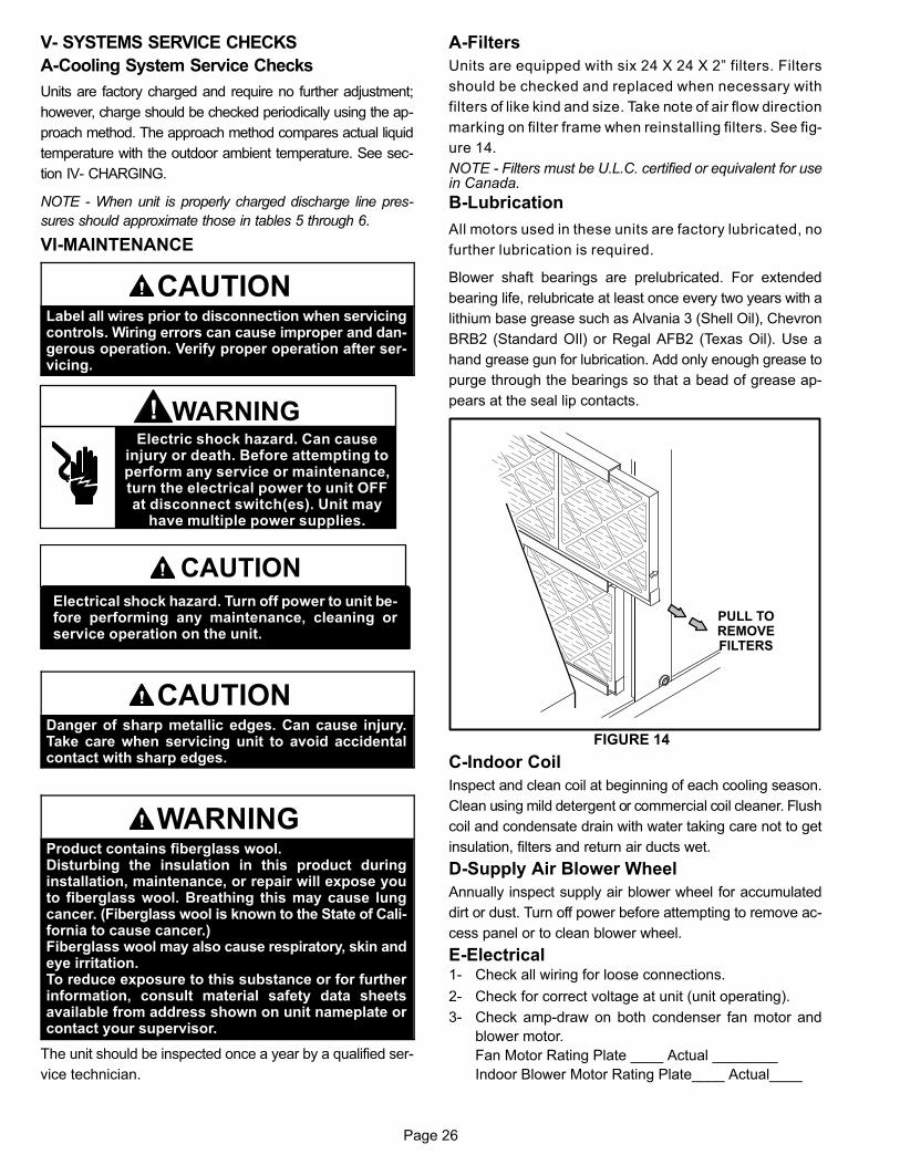
A-Filters
Units are equipped with six 24 X 24 X 2” filters. Filters
should be checked and replaced when necessary with
filters of like kind and size. Take note of air flow direction
marking on filter frame when reinstalling filters. See fig
ure 14.
NOTE - Filters must be U.L.C. certified or equivalent for usein Canada.
B-Lubrication
All motors used in these units are factory lubricated, no
further lubrication is required.
Blower shaft bearings are prelubricated. For extended
bearing life, relubricate at least once every two years with a
lithium base grease such as Alvania 3 (Shell Oil), Chevron
BRB2 (Standard OIl) or Regal AFB2 (Texas Oil). Use a
hand grease gun for lubrication. Add only enough grease to
purge through the bearings so that a bead of grease ap
pears at the seal lip contacts.
FIGURE 14
PULL TOREMOVEFILTERS
C-Indoor Coil
Inspect and clean coil at beginning of each cooling season.
Clean using mild detergent or commercial coil cleaner. Flush
coil and condensate drain with water taking care not to get
insulation, filters and return air ducts wet.
D-Supply Air Blower Wheel
Annually inspect supply air blower wheel for accumulated
dirt or dust. Turn off power before attempting to remove ac
cess panel or to clean blower wheel.
E-Electrical1- Check all wiring for loose connections.
2- Check for correct voltage at unit (unit operating).
3- Check amp-draw on both condenser fan motor and
blower motor.
Fan Motor Rating Plate ____ Actual ________
Indoor Blower Motor Rating Plate____ Actual____

Page 27
TOP VIEW
OUTDOORCOIL
FIGURE 15
1- Remove unit outdoor section top panel and outdoor
coil access panel.
2- Remove screws securing coil end plates to mullions.
3- Remove wire ties connecting coils slabs and separate
slabs 3-4” (76-102mm).
4- Clean coils with detergent or commercial coil cleaner.
5- Rinse thoroughly with water and reassemble.
6- Secure coil slabs together using field-provided
wire ties.
CLEAN CONDENSER COILEND PLATE ISSECURED TO
MULLION
INDOOR COIL
OUTDOORCOIL
OUTDOORCOIL ACCESS
PANEL
END PLATE ISSECURED TO
MULLION
F-Condenser Coil
Clean condenser coil annually with detergent or commer
cial coil cleaner and inspect monthly during the cooling sea
son. Access panels are provided on the front and back of
the condenser section.
Outdoor coils are made of two formed slabs. Dirt and debris
may become trapped between the slabs. To clean between
slabs, carefully separate coil slabs and wash them thor
oughly. See figure 15. Flush coils with water following
cleaning.
NOTE - Remove all screws and gaskets prior to cleaning
procedure and replace upon completion.
VII-OPTIONAL ACCESSORIES The accessories section describes the application of most of
the optional accessories.
A-C1CURB, LARMF and LARMFH Mounting
Frames
When installing units on a combustible surface for down
flow discharge applications, the C1CURB40 (8-inch), or
LARMF18/30S or 18/36 14‐inch, 18-inch or 24‐inch (356
mm or 610mm) roof mounting frame is used. An adjustable,
pitched curb (L1CURB55C) is also available. For horizontal
discharge applications, use LARMFH18/24 26‐inch or
37‐inch (660mm or 940mm) roof mounting frame. This
frame converts unit from downflow to horizontal air flow.
The roof mounting frames are recommended in all other
applications but not required. If the units are not mounted
on a flat (roof) surface, they MUST be supported under all
edges and under the middle of the unit to prevent sagging.
The units MUST be mounted level within 1/16” per linear
foot or 5mm per meter in any direction.
The assembled mounting frame is shown in figure 16. Re
fer to the roof mounting frame installation instructions for
details of proper assembly and mounting. The roof mount
ing frame MUST be squared to the roof and level before
mounting. Plenum system MUST be installed before the
unit is set on the mounting frame. Typical roof curbing and
flashing is shown in figure 17. Refer to the roof mounting
frame installation instructions for proper plenum construc
tion and attachment.
B-Transitions
Optional supply/return transitions LASRT18 and LASRT21/24
are available for use with units utilizing optional LARMF18/36
roof mounting frame. Transition must be installed in the mount
ing frame before setting the unit on the frame. Refer to the
manufacturer's instructions included with the transition for de
tailed installation procedures.
C-Supply and Return Diffusers (all units)
Optional flush mount diffuser/return FD11 and extended
mount diffuser/return RTD11 are available for use with all
units. Refer to manufacturer's instructions included with
transition for detailed installation procedures.
FIGURE 16
ASSEMBLED ROOF MOUNTING FRAME
FRONT
END
END
BACK
CENTER SUPPORTS(TWO PIECES EACH)
Page 28
FIGURE 17
ROOFMOUNTING FRAME
(Extends around entireperimeter of unit)
FIBERGLASSINSULATION(Furnished)
COUNTER FLASHING(Field Supplied)
UNIT BASEBOTTOM
RIGID INSULATION(Field Supplied)
ROOFINGMATERIAL
CANT STRIP(Field Supplied)
NAILER STRIP(Furnished)
UNIT BASERAIL
TYPICAL FLASHING DETAIL
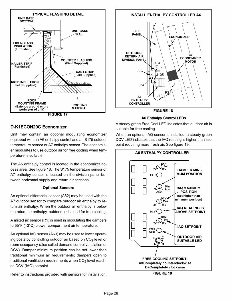
D-K1ECON20C Economizer
Unit may contain an optional modulating economizer
equipped with an A6 enthalpy control and an S175 outdoor
temperature sensor or A7 enthalpy sensor. The economiz
er modulates to use outdoor air for free cooling when tem
perature is suitable.
The A6 enthalpy control is located in the economizer ac
cess area. See figure 18. The S175 temperature sensor or
A7 enthalpy sensor is located on the division panel be
tween horizontal supply and return air sections.
Optional Sensors
An optional differential sensor (A62) may be used with the
A7 outdoor sensor to compare outdoor air enthalpy to re
turn air enthalpy. When the outdoor air enthalpy is below
the return air enthalpy, outdoor air is used for free cooling.
A mixed air sensor (R1) is used in modulating the dampers
to 55°F (13°C) blower compartment air temperature.
An optional IAQ sensor (A63) may be used to lower operat
ing costs by controlling outdoor air based on CO2 level or
room occupancy (also called demand control ventilation or
DCV). Damper minimum position can be set lower than
traditional minimum air requirements; dampers open to
traditional ventilation requirements when CO2 level reach
es DCV (IAQ) setpoint.
Refer to instructions provided with sensors for installation.
FIGURE 18
INSTALL ENTHALPY CONTROLLER A6
B7ECONOMIZER
MOTORJ104
J105
A6ENTHALPY
CONTROLLER
J3
ECONOMIZER
P4
OUTDOOR/RETURN AIR
DIVISION PANEL
SIDEPANEL
J10P3
A6 Enthalpy Control LEDs
A steady green Free Cool LED indicates that outdoor air is
suitable for free cooling.
When an optional IAQ sensor is installed, a steady green
DCV LED indicates that the IAQ reading is higher than set
point requiring more fresh air. See figure 19.
FIGURE 19
A6 ENTHALPY CONTROLLER
A
B C
D
Open
MinPos
FREE COOLING SETPOINT;
A=Completely counterclockwise
D=Completely clockwise
OUTDOOR AIRSUITABLE LED
FreeCool
DCV
EXH
EXHSet
2V 10V
DCVMax
2V 10V
DCVSet
2V 10V
IAQ SETPOINT
IAQ READING ISABOVE SETPOINT
DAMPER MINIMUM POSITION
IAQ MAXIMUMPOSITION
(set higher than
minimum position)
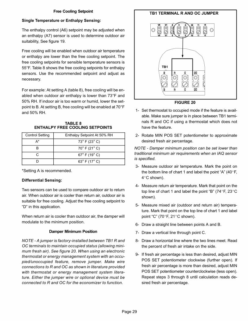
Page 29
Free Cooling Setpoint
Single Temperature or Enthalpy Sensing:
The enthalpy control (A6) setpoint may be adjusted when
an enthalpy (A7) sensor is used to determine outdoor air
suitability, See figure 19.
Free cooling will be enabled when outdoor air temperature
or enthalpy are lower than the free cooling setpoint. The
free cooling setpoints for sensible temperature sensors is
55°F. Table 8 shows the free cooling setpoints for enthalpy
sensors. Use the recommended setpoint and adjust as
necessary.
For example: At setting A (table 8), free cooling will be en
abled when outdoor air enthalpy is lower than 73°F and
50% RH. If indoor air is too warm or humid, lower the set
point to B. At setting B, free cooling will be enabled at 70°F
and 50% RH.
TABLE 8ENTHALPY FREE COOLING SETPOINTS
Control Setting Enthalpy Setpoint At 50% RH
A* 73° F (23° C)
B 70° F (21° C)
C 67° F (19° C)
D 63° F (17° C)
*Setting A is recommended.
Differential Sensing:
Two sensors can be used to compare outdoor air to return
air. When outdoor air is cooler than return air, outdoor air is
suitable for free cooling. Adjust the free cooling setpoint to
“D” in this application.
When return air is cooler than outdoor air, the damper will
modulate to the minimum position.
Damper Minimum Position
NOTE - A jumper is factory-installed between TB1 R and
OC terminals to maintain occupied status (allowing mini
mum fresh air). See figure 20. When using an electronic
thermostat or energy management system with an occu
pied/unoccupied feature, remove jumper. Make wire
connections to R and OC as shown in literature provided
with thermostat or energy management system litera
ture. Either the jumper wire or optional device must be
connected to R and OC for the economizer to function.
FIGURE 20
TB1 TERMINAL R AND OC JUMPER
TB1
1- Set thermostat to occupied mode if the feature is avail
able. Make sure jumper is in place between TB1 termi
nals R and OC if using a thermostat which does not
have the feature.
2- Rotate MIN POS SET potentiometer to approximate
desired fresh air percentage.
NOTE - Damper minimum position can be set lower than
traditional minimum air requirements when an IAQ sensor
is specified.
3- Measure outdoor air temperature. Mark the point on
the bottom line of chart 1 and label the point “A” (40�F,
4�C shown).
4- Measure return air temperature. Mark that point on the
top line of chart 1 and label the point “B” (74�F, 23�C
shown).
5- Measure mixed air (outdoor and return air) tempera
ture. Mark that point on the top line of chart 1 and label
point “C” (70�F, 21�C shown).
6- Draw a straight line between points A and B.
7- Draw a vertical line through point C.
8- Draw a horizontal line where the two lines meet. Read
the percent of fresh air intake on the side.
9- If fresh air percentage is less than desired, adjust MIN
POS SET potentiometer clockwise (further open). If
fresh air percentage is more than desired, adjust MIN
POS SET potentiometer counterclockwise (less open).
Repeat steps 3 through 8 until calculation reads de
sired fresh air percentage.

Page 30
DCV Set and Max Settings
The DCV SET potentiometer is factory-set at approxi
mately 50% of the potentiometer range. Using a standard
1-2000ppm CO2 sensor, dampers will start to open when
the IAQ sensor reads approximately 1000ppm. Adjust
the DCV SET potentiometer to the approximate setting
specified by the controls contractor. Refer to figure 19.
The DCV MAX potentiometer is factory-set at approxi
mately 50% of the potentiometer range or 6VDC. Damp
ers will open approximately half way when CO2 rises
above setpoint. Adjust the DCV MAX potentiometer to
the approximate setting specified by the controls con
tractor. Refer to figure 19.
NOTE - DCV Max must be set higher than economizer mini
mum position setting for proper demand control ventilation.
Economizer Operation
When the outdoor air is suitable, dampers will modulate be
tween minimum position and full open to maintain 55�F
(12.8�C) supply air.
See table 9 for economizer operation when outdoor air is
suitable. See table 10 for economizer operation when out
door air is NOT suitable.
IAQ Sensor
During the occupied period, dampers will open to DCV MAX
when IAQ reading is above setpoint (regardless of thermostat
demand or outdoor air suitability). DCV MAX will NOT override
damper full-open position. The DCV MAX setting may override
damper free cooling position when occupancy is high and out
door air temperatures are low.
NOTE - R1 senses mixed air temperature below 45�F
(7�C), dampers will move to minimum position until mixed
air temperature rises to 48�F (9�C).
-20-29
-10-23
0-18
10-12
20-7
30-1
404
5010
6016
7021
8027
9032
10038
0
10
30
40
50
60
70
80
90
100
20
OUTDOOR AIR TEMPERATURE
0
10
30
40
50
60
70
80
90
100
20
MIXED AND RETURN AIR TEMPERATURE
CHART 1CALCULATE MINIMUM FRESH AIR PERCENTAGE
A
BC
�F�C
�F�C
-20-29
-10-23
0-18
10-12
20-7
30-1
404
5010
6016
7021
8027
9032
10038
�F�C
�F�C
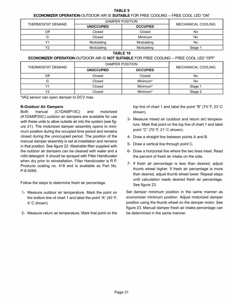
Page 31
TABLE 9
ECONOMIZER OPERATION-OUTDOOR AIR IS SUITABLE FOR FREE COOLING -- FREE COOL LED “ON”
ÁÁÁÁÁÁÁÁÁÁÁÁÁÁÁÁÁÁÁÁ
THERMOSTAT DEMANDÁÁÁÁÁÁÁÁÁÁÁÁÁÁÁÁÁÁÁÁÁÁÁÁÁÁÁÁÁÁÁÁÁÁ
DAMPER POSITION ÁÁÁÁÁÁÁÁÁÁÁÁÁÁÁÁÁÁÁÁÁÁ
MECHANICAL COOLINGÁÁÁÁÁÁÁÁÁUNOCCUPIED ÁÁÁÁÁÁÁÁÁOCCUPIEDÁÁÁÁÁÁÁÁÁÁ
ÁÁÁÁÁÁÁÁÁÁOffÁÁÁÁÁÁÁÁÁÁÁÁÁÁÁÁÁÁClosed
ÁÁÁÁÁÁÁÁÁÁÁÁÁÁÁÁÁÁClosed
ÁÁÁÁÁÁÁÁÁÁÁÁÁÁÁÁÁÁÁÁÁÁNoÁÁÁÁÁÁÁÁÁÁ
ÁÁÁÁÁÁÁÁÁÁGÁÁÁÁÁÁÁÁÁÁÁÁÁÁÁÁÁÁClosed
ÁÁÁÁÁÁÁÁÁÁÁÁÁÁÁÁÁÁMinimum
ÁÁÁÁÁÁÁÁÁÁÁÁÁÁÁÁÁÁÁÁÁÁNoÁÁÁÁÁÁÁÁÁÁ
ÁÁÁÁÁÁÁÁÁÁY1
ÁÁÁÁÁÁÁÁÁÁÁÁÁÁÁÁÁÁ
ModulatingÁÁÁÁÁÁÁÁÁÁÁÁÁÁÁÁÁÁ
ModulatingÁÁÁÁÁÁÁÁÁÁÁÁÁÁÁÁÁÁÁÁÁÁ
NoÁÁÁÁÁÁÁÁÁÁÁÁÁÁÁÁÁÁÁÁ
Y2ÁÁÁÁÁÁÁÁÁÁÁÁÁÁÁÁÁÁ
ModulatingÁÁÁÁÁÁÁÁÁÁÁÁÁÁÁÁÁÁ
ModulatingÁÁÁÁÁÁÁÁÁÁÁÁÁÁÁÁÁÁÁÁÁÁ
Stage 1
TABLE 10
ECONOMIZER OPERATION-OUTDOOR AIR IS NOT SUITABLE FOR FREE COOLING -- FREE COOL LED “OFF”
ÁÁÁÁÁÁÁÁÁÁÁÁÁÁÁÁÁÁÁÁÁÁÁÁÁÁÁÁÁÁ
THERMOSTAT DEMAND
ÁÁÁÁÁÁÁÁÁÁÁÁÁÁÁÁÁÁÁÁÁÁÁÁÁÁÁÁÁÁÁÁÁÁ
DAMPER POSITION ÁÁÁÁÁÁÁÁÁÁÁÁÁÁÁÁÁÁÁÁÁÁÁÁÁÁÁÁÁÁÁÁÁ
MECHANICAL COOLINGÁÁÁÁÁÁÁÁÁÁÁÁÁÁÁÁÁÁ
UNOCCUPIED ÁÁÁÁÁÁÁÁÁÁÁÁÁÁÁÁÁÁ
OCCUPIED
ÁÁÁÁÁÁÁÁÁÁÁÁÁÁÁÁÁÁÁÁ
Off ÁÁÁÁÁÁÁÁÁÁÁÁÁÁÁÁÁÁ
Closed ÁÁÁÁÁÁÁÁÁÁÁÁÁÁÁÁÁÁ
Closed ÁÁÁÁÁÁÁÁÁÁÁÁÁÁÁÁÁÁÁÁÁÁ
No
ÁÁÁÁÁÁÁÁÁÁÁÁÁÁÁÁÁÁÁÁ
G ÁÁÁÁÁÁÁÁÁÁÁÁÁÁÁÁÁÁ
Closed ÁÁÁÁÁÁÁÁÁÁÁÁÁÁÁÁÁÁ
Minimum* ÁÁÁÁÁÁÁÁÁÁÁÁÁÁÁÁÁÁÁÁÁÁ
No
ÁÁÁÁÁÁÁÁÁÁÁÁÁÁÁÁÁÁÁÁ
Y1 ÁÁÁÁÁÁÁÁÁÁÁÁÁÁÁÁÁÁ
Closed ÁÁÁÁÁÁÁÁÁÁÁÁÁÁÁÁÁÁ
Minimum* ÁÁÁÁÁÁÁÁÁÁÁÁÁÁÁÁÁÁÁÁÁÁ
Stage 1
ÁÁÁÁÁÁÁÁÁÁÁÁÁÁÁÁÁÁÁÁ
Y2 ÁÁÁÁÁÁÁÁÁÁÁÁÁÁÁÁÁÁ
Closed ÁÁÁÁÁÁÁÁÁÁÁÁÁÁÁÁÁÁ
Minimum* ÁÁÁÁÁÁÁÁÁÁÁÁÁÁÁÁÁÁÁÁÁÁ
Stage 2
*IAQ sensor can open damper to DCV max.
B-Outdoor Air Dampers
Both manual (C1DAMP10C) and motorized
(K1DAMP20C) outdoor air dampers are available for use
with these units to allow outside air into the system (see fig
ure 21). The motorized damper assembly opens to mini
mum position during the occupied time period and remains
closed during the unoccupied period. The position of the
manual damper assembly is set at installation and remains
in that position. See figure 22. Washable filter supplied with
the outdoor air dampers can be cleaned with water and a
mild detergent. It should be sprayed with Filter Handicoater
when dry prior to reinstallation. Filter Handicoater is R.P.
Products coating no. 418 and is available as Part No.
P-8-5069.
Follow the steps to determine fresh air percentage
1- Measure outdoor air temperature. Mark the point on
the bottom line of chart 1 and label the point “A” (40�F,
4�C shown).
2- Measure return air temperature. Mark that point on the
top line of chart 1 and label the point “B” (74�F, 23�C
shown).
3- Measure mixed air (outdoor and return air) tempera
ture. Mark that point on the top line of chart 1 and label
point “C” (70�F, 21�C shown).
4- Draw a straight line between points A and B.
5- Draw a vertical line through point C.
6- Draw a horizontal line where the two lines meet. Read
the percent of fresh air intake on the side.
7- If fresh air percentage is less than desired, adjust
thumb wheel higher. If fresh air percentage is more
than desired, adjust thumb wheel lower. Repeat steps
until calculation reads desired fresh air percentage.
See figure 23.
Set damper minimum position in the same manner as
economizer minimum position. Adjust motorized damper
position using the thumb wheel on the damper motor. See
figure 23. Manual damper fresh air intake percentage can
be determined in the same manner.
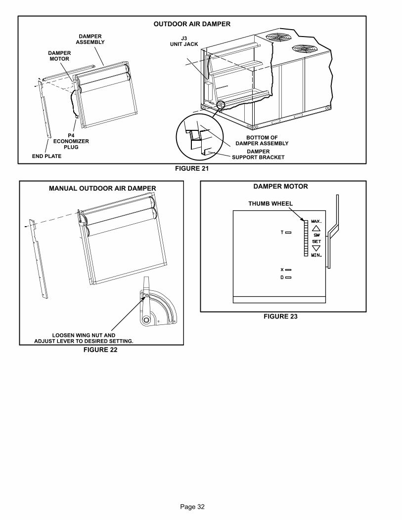
Page 32
BOTTOM OFDAMPER ASSEMBLY
DAMPERSUPPORT BRACKET
DAMPERASSEMBLY
END PLATE
DAMPERMOTOR
OUTDOOR AIR DAMPER
P4ECONOMIZER
PLUG
J3UNIT JACK
FIGURE 21
MANUAL OUTDOOR AIR DAMPER
FIGURE 22
LOOSEN WING NUT ANDADJUST LEVER TO DESIRED SETTING.
FIGURE 23
DAMPER MOTOR
THUMB WHEEL
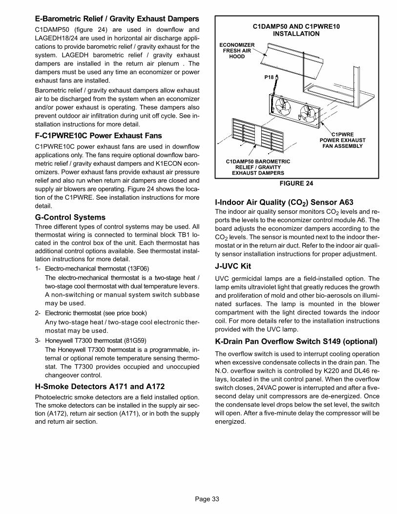
Page 33
E-Barometric Relief / Gravity Exhaust Dampers
C1DAMP50 (figure 24) are used in downflow and
LAGEDH18/24 are used in horizontal air discharge appli
cations to provide barometric relief / gravity exhaust for the
system. LAGEDH barometric relief / gravity exhaust
dampers are installed in the return air plenum . The
dampers must be used any time an economizer or power
exhaust fans are installed.
Barometric relief / gravity exhaust dampers allow exhaust
air to be discharged from the system when an economizer
and/or power exhaust is operating. These dampers also
prevent outdoor air infiltration during unit off cycle. See in
stallation instructions for more detail.
F-C1PWRE10C Power Exhaust Fans
C1PWRE10C power exhaust fans are used in downflow
applications only. The fans require optional downflow baro
metric relief / gravity exhaust dampers and K1ECON econ
omizers. Power exhaust fans provide exhaust air pressure
relief and also run when return air dampers are closed and
supply air blowers are operating. Figure 24 shows the loca
tion of the C1PWRE. See installation instructions for more
detail.
G-Control SystemsThree different types of control systems may be used. All
thermostat wiring is connected to terminal block TB1 lo
cated in the control box of the unit. Each thermostat has
additional control options available. See thermostat instal
lation instructions for more detail.
1- Electro‐mechanical thermostat (13F06)
The electro‐mechanical thermostat is a two-stage heat /
two-stage cool thermostat with dual temperature levers.
A non‐switching or manual system switch subbase
may be used.
2- Electronic thermostat (see price book)
Any two-stage heat / two-stage cool electronic ther
mostat may be used.
3- Honeywell T7300 thermostat (81G59)
The Honeywell T7300 thermostat is a programmable, in
ternal or optional remote temperature sensing thermo
stat. The T7300 provides occupied and unoccupied
changeover control.
H-Smoke Detectors A171 and A172
Photoelectric smoke detectors are a field installed option.
The smoke detectors can be installed in the supply air sec
tion (A172), return air section (A171), or in both the supply
and return air section.
FIGURE 24
C1PWREPOWER EXHAUSTFAN ASSEMBLY
C1DAMP50 BAROMETRICRELIEF / GRAVITY
EXHAUST DAMPERS
ECONOMIZERFRESH AIR
HOOD
P18
C1DAMP50 AND C1PWRE10INSTALLATION
I-Indoor Air Quality (CO2) Sensor A63The indoor air quality sensor monitors CO2 levels and re
ports the levels to the economizer control module A6. The
board adjusts the economizer dampers according to the
CO2 levels. The sensor is mounted next to the indoor ther
mostat or in the return air duct. Refer to the indoor air quali
ty sensor installation instructions for proper adjustment.
J-UVC Kit
UVC germicidal lamps are a field-installed option. The
lamp emits ultraviolet light that greatly reduces the growth
and proliferation of mold and other bio-aerosols on illumi
nated surfaces. The lamp is mounted in the blower
compartment with the light directed towards the indoor
coil. For more details refer to the installation instructions
provided with the UVC lamp.
K-Drain Pan Overflow Switch S149 (optional)
The overflow switch is used to interrupt cooling operation
when excessive condensate collects in the drain pan. The
N.O. overflow switch is controlled by K220 and DL46 re
lays, located in the unit control panel. When the overflow
switch closes, 24VAC power is interrupted and after a five-
second delay unit compressors are de-energized. Once
the condensate level drops below the set level, the switch
will open. After a five-minute delay the compressor will be
energized.
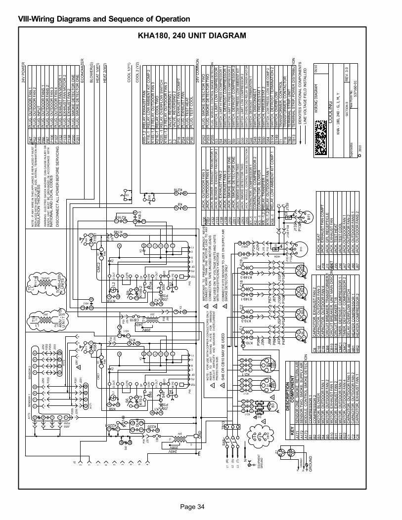
Page 34
VIII-Wiring Diagrams and Sequence of Operation
KHA180, 240 UNIT DIAGRAM
CO
OLIN
G
RE
V.
3.0
LIN
E V
OLTA
GE
FIE
LD
IN
STA
LLE
D
DE
NO
TE
S O
PT
ION
AL C
OM
PO
NE
NT
S
4
S1
49
K220-1
DL
46
K220
2 7 A B25
13
B2
HR
1H
R2
12
312
J2
4
P2
4
7 4
9 6
208V240V
240V T1
8CB18
S4
S4
9
74
1
A B
2 85
L2L1
460V
- 5
75V
U N
I T
S
K2-1
B5
208V
95
96
GR
OU
ND
S4
6
K1
0-2
28
S6
28
L2
S9
K1
49
-2 S1
04
S5
0 S7
CM
C2
B2
1B
22
17 4
K10-1
9 6
7 4
9 6
K149-1
K149-3
33
33
12
3
12
J138 P
138
J1
392 1
B11
J1
33
P1
33
TB
13
S4
8
396
47
K8
-3
K216-1
P4
7P
52
P1
06
P1
07
J4
7J5
2J1
06
J1
07
C8
K10-3G
ND
N
T1
8
3 J35P35
J35P35
4
2
5
68
P3
6J3
6
J8
6
P8
6
1 12
3
2 45
6
34
P8
7
J8
71
23
45
6
21
21
21
21
C1
C2
C1
8C
19
24V
CO
MM
ON
CO
OL 1
(Y1)
HE
AT
1(W
1)
BL
OW
ER
(G)
24V
PO
WE
R
EC
ON
OM
IZE
R
HE
AT
2(W
2)
CO
OL 2
(Y
2)
K5
8-11
7K
11
8-11
7
S42 U
SE
D O
N ”
M”
VO
LTA
GE
UN
ITS
AN
D U
NIT
SW
ITH
HIG
H E
FF
ICIE
NC
Y M
OT
OR
S
S48 O
R C
B10 M
AY
BE
US
ED
CO
NN
EC
T A
172 S
EN
SO
R T
O J
261 O
N S
UP
PLY
AIR
SM
OK
E D
ET
EC
TO
R O
NLY
IMP
OR
TA
NT: T
O
PR
EV
EN
T M
OT
OR
B
UR
NO
UT,
NE
VE
RC
ON
NE
CT
M
OR
E T
HA
N
ON
E
MO
TO
R
LE
AD
T
O A
NY
O
NE
CO
NN
EC
TIO
N. TA
PE
UN
US
ED
MO
TO
R L
EA
DS
DE
SC
RIP
TIO
NK
EY
CO
MP
ON
EN
T
A1
71
SE
NS
OR
ON
E, S
MO
KE
, R
ET
UR
N A
IR
A1
72
SE
NS
OR
TW
O, S
MO
KE
, S
UP
PLY
AIR
A1
73
MO
DU
LE
, C
ON
TR
OL S
MO
KE
DE
TE
CT
ION
B1
CO
MP
RE
SS
OR
1
B2
CO
MP
RE
SS
OR
2
B3
MO
TO
R, B
LO
WE
R
B4
MO
TO
R, O
UT
DO
OR
FA
N 1
B5
MO
TO
R, O
UT
DO
OR
FA
N 2
B1
0M
OT
OR
, E
XH
AU
ST
FA
N 1
B11
MO
TO
R, E
XH
AU
ST
FA
N 2
B2
1M
OT
OR
, O
UT
DO
OR
FA
N 3
B2
2M
OT
OR
, O
UT
DO
OR
FA
N 4
C1
CA
PA
CIT
OR
, O
UT
DO
OR
FA
N 1
C2
CA
PA
CIT
OR
, O
UT
DO
OR
FA
N 2
C6
CA
PA
CIT
OR
, E
XH
AU
ST
FA
N 1
C8
CA
PA
CIT
OR
, E
XH
AU
ST
FA
N 2
C1
8C
AP
AC
ITO
R, O
UT
DO
OR
FA
N 3
C1
9C
AP
AC
ITO
R, O
UT
DO
OR
FA
N 4
CB
8C
IRC
UIT
BR
EA
KE
R, T
RA
NS
FO
RM
ER
1
CB
10
CIR
CU
IT B
RE
AK
ER
, U
NIT
MA
IN D
ISC
ON
NE
CT
CB
18
CIR
CU
IT, B
RE
AK
ER
T18
CM
C1
TIM
ER
, D
EF
RO
ST, C
OM
PR
ES
SO
R 1
CM
C2
TIM
ER
, D
EF
RO
ST, C
OM
PR
ES
SO
R 2
DL
46
DE
LA
Y, O
VE
RF
LO
W S
WIT
CH
HR
1H
EA
TE
R C
OM
PR
ES
SO
R 1
HR
2H
EA
TE
R C
OM
PR
ES
SO
R 2
J2
JA
CK
, H
EA
T
J1
8JA
CK
, E
XH
AU
ST
FA
N C
OM
PT
J11
JA
CK
, G
FI, R
EC
EP
TIC
LE
J2
4JA
CK
, E
XH
AU
ST
FA
N
J3
5JA
CK
, T
ES
T H
EA
T
J3
6JA
CK
, T
ES
T C
OO
L
J4
7JA
CK
,OU
TD
OO
R F
AN
1
J5
2JA
CK
,OU
TD
OO
R F
AN
2
J8
6JA
CK
, O
UT
DO
OR
FA
NS
1
J8
7JA
CK
, O
UT
DO
OR
FA
NS
2
J1
06
JA
CK
, O
UT
DO
OR
FA
N 3
J1
07
JA
CK
, O
UT
DO
OR
FA
N 4
J1
32
JA
CK
, B
LO
WE
R , E
XH
AU
ST
FA
N M
OT
OR
1
J1
33
JA
CK
, B
LO
WE
R , E
XH
AU
ST
FA
N M
OT
OR
2
J1
38
JA
CK
, E
XH
AU
ST
FA
N 2
J1
39
JA
CK
, E
XH
AU
ST
FA
N 3
J2
50
JA
CK
, S
MO
KE
DE
TE
CT
OR
ON
E
J2
51
JA
CK
, S
MO
KE
DE
TE
CT
OR
ON
E
J2
52
JA
CK
, S
MO
KE
DE
TE
CT
OR
TW
O
J2
53
JA
CK
, S
MO
KE
DE
TE
CT
OR
TW
O
J2
55
JA
CK
, M
OD
UL
E,
CO
NT
RO
L S
MO
KE
DE
TE
CT
ION
K1
,-1
CO
NTA
CT
OR
, C
OM
PR
ES
SO
R 1
K2
,-1
CO
NTA
CT
OR
, C
OM
PR
ES
SO
R 2
K3, -1
CO
NTA
CT
OR
, B
LO
WE
R
K8, -1
,2,3
RE
LA
Y, T
RA
NS
FE
R 1
K1
0,-
1,2
,3R
ELA
Y, O
UT
DO
OR
FA
N 1
K5
8,-
1R
ELA
Y, LO
W A
MB
IEN
T K
IT C
OM
P 1
K65-1
,2R
ELA
Y, E
XH
AU
ST
FA
N
K118,-
1R
ELA
Y, LO
W A
MB
IEN
T K
IT C
OM
P 2
K149,-
1,2
,3 R
ELA
Y, O
UT
DO
OR
FA
N 3
K216,-
1R
ELA
Y, C
OO
L T
WO
K220, -1
RE
LA
Y, O
VE
RF
LO
W S
WIT
CH
K149,-
1,2
,3 R
ELA
Y, O
UT
DO
OR
FA
N 3
L1
VA
LV
E, R
EV
ER
SIN
G 1
L2
VA
LV
E, R
EV
ER
SIN
G 2
P1
8P
LU
G, E
XH
AU
ST
FA
N C
OM
PT
P2
4P
LU
G, E
XH
AU
ST
FA
N
P3
5P
LU
G, T
ES
T H
EA
T
P3
6P
LU
G, T
ES
T C
OO
L
P4
7P
LU
G, O
UT
DO
OR
FA
N 1
P5
2P
LU
G, O
UT
DO
OR
FA
N 2
P4
5P
LU
G, IN
PU
T
P8
6P
LU
G, O
UT
DO
OR
FA
NS
1
P8
7P
LU
G, O
UT
DO
OR
FA
NS
2
P1
06
PLU
G, O
UT
DO
OR
FA
N 3
P1
07
PLU
G, O
UT
DO
OR
FA
N 4
P1
32
PLU
G, E
XH
AU
ST
FA
N M
OT
OR
1
P1
33
PLU
G, E
XH
AU
ST
FA
N M
OT
OR
2
P1
38
PLU
G, E
XH
AU
ST
FA
N 2
P2
50
PLU
G, S
MO
KE
DE
TE
CT
OR
ON
E
P2
51
PLU
G, S
MO
KE
DE
TE
CT
OR
ON
E
P2
52
PLU
G, S
MO
KE
DE
TE
CT
OR
TW
O
P2
53
PLU
G, S
MO
KE
DE
TE
CT
OR
TW
O
P2
55
PL
UG
, M
OD
UL
E,
CO
NT
RO
L S
MO
KE
DE
TE
CT
ION
S3
SW
ITC
H, LIM
IT L
OW
CO
MP
RE
SS
OR
1
S4
SW
ITC
H, LIM
IT H
I P
RE
SS
CO
MP
RE
SS
OR
1
S6
SW
ITC
H, D
EF
RO
ST
CO
MP
RE
SS
OR
1
S7
SW
ITC
H, LIM
IT H
I P
RE
SS
CO
MP
RE
SS
OR
2
S9
SW
ITC
H, D
EF
RO
ST
CO
MP
RE
SS
OR
2
S11
SW
ITC
H, LO
W P
RE
SS
, LO
W A
MB
IEN
T K
IT
S30
SW
ITC
H, LIM
IT L
OW
CO
MP
RE
SS
OR
2
S42
SW
ITC
H,
OV
ER
LO
AD
RE
LA
Y B
LO
WE
R M
OT
OR
S46
SW
ITC
H, D
EF
RO
ST
TE
RM
INA
TIO
N 1
S4
8S
WIT
CH
, D
ISC
ON
NE
CT
S4
9S
WIT
CH
, F
RE
EZ
ES
TA
T 1
S5
0S
WIT
CH
, F
RE
EZ
ES
TA
T 2
S8
4S
IWT
CH
, LO
W P
RE
SS
, LO
W A
MB
CO
MP
2
S1
04
SW
ITC
H, D
EF
RO
ST
TE
RM
INA
TIO
N 2
S1
49
SW
ITC
H, O
VE
RF
LO
W
T1
TR
AN
SF
OR
ME
R, C
ON
TR
OL
T1
8T
RA
NS
FO
RM
ER
, C
ON
TA
CT
OR
TB
2T
ER
MIN
AL S
TR
IP, U
NIT
TB
13
TE
RM
INA
L S
TR
IP, P
OW
ER
DIS
TR
IBU
TIO
N
TO
L1
TO
N3
80
-42
0V
UN
ITS
B3
K216
A B
K8
A B
K149
A B
K10
A B
K1
B A
K2
B A
K58A B
K118
A B
NO
TE
- I
F A
NY
WIR
E I
N T
HIS
AP
PL
IAN
CE
IS
RE
PL
AC
ED
IT
MU
ST
B
E
RE
PL
AC
ED
WIT
H W
IRE
OF
LIK
E
SIZ
E,
RA
TIN
G,
TE
RM
INA
TIO
N A
ND
INS
ULA
TIO
N T
HIC
KN
ES
S
WA
RN
ING
- E
LE
CT
RIC
SH
OC
K H
AZ
AR
D,
CA
N C
AU
SE
IN
JU
RY
OR
DE
AT
H
UN
IT
MU
ST
B
E
GR
OU
ND
ED
IN
A
CC
OR
DA
NC
E
WIT
H
NA
TIO
NA
L A
ND
LO
CA
L C
OD
ES
DIS
CO
NN
EC
T A
LL P
OW
ER
BE
FO
RE
SE
RV
ICIN
G.
Page 35
KHA180, 240 SEQUENCE OF OPERATIONPower:
1- Line voltage from TB13 energizes transformer T1 and
T18. T1 provides 24VAC to the unit cooling, heating,
blower controls, CMC1, CMC2, reversing valve L1 and
TB1. T18 provides 24VAC to reversing valve L2.
Blower Operation:
2- TB1 receives a demand from thermostat terminal G
and energizes blower contactor K3 24VAC.
3- N.O. K3 closes, energizing blower B3.
Optional Power Exhaust Operation:
4- The economizer control module receives a demand
and energizes exhaust fan relay K65 with 24VAC at
50% outside air damper open (adjustable).
5- N.O. K65-1 and N.O. K65-2 both close, energizing ex
haust fan motors B10 and B11.
1st Stage Cooling (compressor B1)
6- First stage cooling demand routed from thermostat pro
vides 24VAC to Y1 and G on TB1. G energizes blower
(see step 3-)
7- 24VAC routed from T1 energizes reversing valve L1.
8- 24VAC routed from CMC1 proving N.C. high pressure
switch S4 and N.C. freezestat S49. Compressor contactor
K1 is energized.
9- K1 closes energizing compressor B1.
10-24VAC is routed through optional optional N.O. low ambi
ent pressure switch S11 (now closed) to energize outdoor
fan contactor K10.
11- N.O. K10-1 and K10-3 close energizing outdoor fan B4
and B5.
2nd Stage Cooling (compressor B2 is energized)
12- Second stage cooling demand energizes Y2.
13- 24VAC routed from T18 energizes reversing valve L2.
14- 24VAC is routed from CMC2 proving N.C. high pres
sure switch S7 to energize compressor contactor K2.
15- N.O. K2 closes energizing compressor B2.
16- 24VAC is routed through N.O. low ambient pressure
switch S84 (now closed) to energize outdoor fan con
tactor K149.
17- N.O. K149-1 and K149-3 close energizing outdoor fan
B21 and B22.
First Stage Heat (compressors B1 and B2)
NOTE: On first heating demand after unit has been in
cooling mode, unit will de-energize reversing valves L1
and L2.
18- Heating demand energizes W1 in the thermostat.
19- CMC1 and CMC2 prove N.C. high pressure switches
S4 and S7 and N.C. freezestats S49 and S50; com
pressor contactors K1 and K2 are energized.
20- K1 and K2 close energizing compressor B1 and B2.
21- 24VAC bypasses optional N.C. low ambient switches
S11 and S84 to energize outdoor fan relays K10 and
K149.
22- K10 and K149 close energizing outdoor fans B4, B5,
B21 and B22.
Second Stage Heat (electric heat):
23- Second stage heat demand energizes W2 in the
thermostat.
24- See sequence of operation for electric heat.
Defrost Mode
25- During heating operation, when outdoor coil drops to 35
± 4° the defrost thermostat S6 or S9 closes initiating de
frost (after minimum run time of 30, 60 or 90 minutes).
26- When defrost begins, the reversing valve L1 or L2 is
energized. Supplemental electric heat (W2) is ener
gized when stage 1 is in defrost mode.
27- When L1 energizes, outdoor fan relay K10 and outdoor
fans B4 and B5 are de-energized. When L2 energizes,
outdoor fan relay K149 and outdoor fans B21 and B22
are de-energized.
28- Defrost terminates when the pressure switch for the cir
cuit S46 or S104 opens, or when 15 minutes has
elapsed. The defrost cycle is not terminated when ther
mostat demand ends.
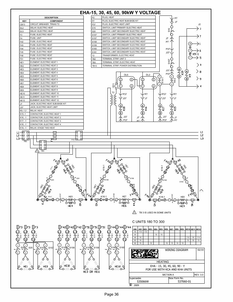
Page 36
EHA-15, 30, 45, 60, 90kW Y VOLTAGE
HEATING
REV. 3.0
KW HE1 HE2 HE3 HE4 HE5 HE6 HE7 HE8 HE9 HE10 HE11 HE12
15 7.5 7.5
30 15 15
45 15 7.5 15 7.5
60 15 15 15 15
90 15 15 15 15 15 15
K9
-2
K1
9-1
S20 S20 S157 S157 S158 S158 S159 S159 S160 S160
S20 S158
K1
6-1
K16-1
K1
6-1
S160
K1
8-1
K18-1
k1
8-1
DESCRIPTION
KEY COMPONENT
CB13 CIRCUIT, BREAKER TRNAS T2
DL2 DELAY, ELECTRIC HEAT
DL5 DELAY, ELECTRIC HEAT
F3 FUSE, ELECTRIC HEAT
F4 FUSE, UNIT
F42 FUSE, ELECTRIC HEAT
F43 FUSE, ELECTRIC HEAT
F44 FUSE, ELECTRIC HEAT
F45 FUSE, ELECTRIC HEAT
F46 FUSE, ELECTRIC HEAT
F51 FUSE, ELECTRIC HEAT
HE1 ELEMENT, ELECTRIC HEAT 1
HE2 ELEMENT, ELECTRIC HEAT 2
HE3 ELEMENT, ELECTRIC HEAT 3
HE4 ELEMENT, ELECTRIC HEAT 4
HE5 ELEMENT, ELECTRIC HEAT 5
HE6 ELEMENT, ELECTRIC HEAT 6
HE7 ELEMENT, ELECTRIC HEAT 7
HE8 ELEMENT, ELECTRIC HEAT 8
HE9 ELEMENT, ELECTRIC HEAT 9
HE10 ELEMENT, ELECTRIC HEAT 10
HE11 ELEMENT, ELECTRIC HEAT 11
HE12 ELEMENT, ELECTRIC HEAT 12
J7 JACK, ELECTRIC HEAT SUB-BASE KIT
J37 JACK, ELECTRIC HEAT LIMIT
K9,-1,2 RELAY, HEAT
K15,-1 CONTACTOR, ELECTRIC HEAT 1
K16, -1 CONTACTOR, ELECTRIC HEAT 2
K17, -1 CONTACTOR, ELECTRIC HEAT 3
K18, -1 CONTACTOR, ELECTRIC HEAT 4
K19, -1 RELAY, STAGE TWO HEAT
P2 PLUG, HEAT
P7 PLUG, ELECTRIC HEAT BUB BASE KIT
P37 PLUG, ELECTRIC HEAT LIMIT
S15 SWITCH, LIMIT PRIMARY ELECTRIC HEAT
S20 SWITCH, LIMIT SECONDARY ELECTRIC HEAT
S107 SWITCH, LIMIT PRIMARY ELECTRIC HEAT
S157 SWITCH, LIMIT SECONDARY ELECTRIC HEAT
S158 SWITCH, LIMIT SECONDARY ELECTRIC HEAT
S159 SWITCH, LIMIT SECONDARY ELECTRIC HEAT
S160 SWITCH, LIMIT SECONDARY ELECTRIC HEAT
S161 SWITCH, LIMIT SECONDARY ELECTRIC HEAT
T2 TRANSFORMER, ELECTRIC HEAT
TB2 TERMINAL STRIP, UNIT 2
TB3 TERMINAL STRIP, ELECTRIC HEAT
TB13 TERMINAL STRIP, POWER DISTRIBUTION
S159
S158
S161
S160
S157
S20

Page 37
EHA-15, 30, 45, 60, 90kW - G, J, M VOLTAGE
HEATING
REV. 0.0
K9
A
B
KW HE1 HE1A HE2A HE3 HE4 HE5 HE6 HE7
15 7.5 7.5
30 15 15
45 15 7.5 15 7.5
60 15 15 15 15
90 15 15 15 15 15 15
1
1
K1
8
A
B
K1
5
A
B
K1
6
A
B
K1
7
A
B
K1
9
A
B
DESCRIPTION
KEY COMPONENT
CB13 CIRCUIT, BREAKER TRNAS T2
DL2 DELAY, ELECTRIC HEAT
DL5 DELAY, ELECTRIC HEAT
F3 FUSE, ELECTRIC HEAT 1, 1A, 2A
F4 FUSE, UNIT
F43 FUSE, ELECTRIC HEAT 3, 4
F44 FUSE, ELECTRIC HEAT 5
F45 FUSE, ELECTRIC HEAT 6, 7
HE1 ELEMENT, ELECTRIC HEAT 1
HE1A ELEMENT, ELECTRIC HEAT 1A
HE2A ELEMENT, ELECTRIC HEAT 2
HE3 ELEMENT, ELECTRIC HEAT 3
HE4 ELEMENT, ELECTRIC HEAT 4
HE5 ELEMENT, ELECTRIC HEAT 5
HE6 ELEMENT, ELECTRIC HEAT 6
HE7 ELEMENT, ELECTRIC HEAT 7
J7 JACK, ELECTRIC HEAT SUB-BASE KIT
J37 JACK, ELECTRIC HEAT LIMIT
K9,-1,2 RELAY, HEAT
K15,-1 CONTACTOR, ELECTRIC HEAT 1
K16, -1 CONTACTOR, ELECTRIC HEAT 2
K17, -1 CONTACTOR, ELECTRIC HEAT 3
K18, -1 CONTACTOR, ELECTRIC HEAT 4
K19, -1 RELAY, STAGE TWO HEAT
P2 PLUG, HEAT
P7 PLUG, ELECTRIC HEAT BUB BASE KIT
P37 PLUG, ELECTRIC HEAT LIMIT
S15 SWITCH, LIMIT PRIMARY ELECTRIC HEAT
S20 SWITCH, LIMIT SECONDARY ELECTRIC HEAT 1A
S107 SWITCH, LIMIT PRIMARY ELECTRIC HEAT
S157 SWITCH, LIMIT SECONDARY ELECTRIC HEAT 2A
S158 SWITCH, LIMIT SECONDARY ELECTRIC HEAT 3,4
S159 SWITCH, LIMIT SECONDARY ELECTRIC HEAT 5
S160 SWITCH, LIMIT SECONDARY ELECTRIC HEAT 6,7
T2 TRANSFORMER, ELECTRIC HEAT
TB 2 TERMINAL STRIP, UNIT 2
TB 3 TERMINAL STRIP, ELECTRIC HEAT
TB15 TERMINAL STRIP, UNIT 2
Page 38
Sequence of Operation - EHA15 ,30, 45, 60, 90kW - Y, G, J and MNOTE: This sequence of operation is for all Electric Heat
kW ratings Y, G, J and M voltages.
HEATING ELEMENTS:
1- Terminal Strip TB2 supplies power to TB3. TB3 sup
plies line voltage to electric heat elements HE1 through
HE7 in G, J and M volt units. TB3 supplies line voltage
to electric heat elements HE1 through HE12 in Y volt
units. Each element is protected by fuse F3.
SECOND STAGE HEAT DEMAND:
Heating demand initiates at W2 in thermostat.
2- 24VAC is routed from T2, proving N.C. primary limits
S15 (first heat section) and S107 (second heat sec
tion). Voltage then energizes contactors K15 and K17.
24VAC is routed through P2 energizing relays K9 and
K19. N.O. K9-2 and K19-1 close.
3- N.O. contact K15-1 closes allowing the first bank of ele
ments to be energized. N.O. K17-1 closes allowing the
second bank of elements to be energized.
4- Relay K19 is energized. N.O. contacts K19-1 close en
ergizing timer DL2.
With the first stage heat operating, an additional heat
ing demand initiates at W2 in the thermostat.
5- After a 30 second delay, DL2 closes energizing contac
tor K16 and timer DL5.
6- N.O. contacts K16-1 close allowing the third bank of
elements to be energized.
7- After a 30 second delay, DL5 closes energizing contac
tor K18. K18-1 closes allowing the fourth bank of ele
ments to be energized.
SECOND STAGE HEAT DEMAND SATISFIED:
Heating demand is satisfied. Terminal W2 in the ther
mostat is de-energized.
8- Electric heat contactors K15 and K17 are de-ener
gized.
9- The second and first set of elements are de-energized.
10- Electric heat contactors K16 and K18 are de-ener
gized.
11- The fourth and third set of elements are de-energized.
Heating demand is satisfied. Terminal W2 in the ther
mostat is de-energized.

Page 39
ELECTRONIC OR ELECTROMECHANICAL THERMOSTAT
POWER:
1- Terminal strip TB1 found on the control panel energizes thermostat components with 24VAC.
OPERATION:
2- TB1 receives data from the electronic thermostat A2 (Y1, Y2, W1, W2, G, OCP)TB1 energizes the appropriate components for heat or cool demand.
ACCESSORIES
REV. 2.0
REMOVEP3 WHEN ECONOMIZERIS USED, ONLY ON KCA,
KGA AND KHA 180 THROUGH 300 UNITS.
HEAT 2(W2)
ECONOMIZER
24V POWER
BLOWER(G)
HEAT 1(W1)
COOL 1(Y1)
24V COMMON
COOL 2(Y2)
TOUCHSCREEN THERMOSTAT
DESCRIPTION
KEY COMPONENT
A2 SENSOR, ELECTRONIC THERMOSTAT
A63 SENSOR, CO2
CMC3 CLOCK, TIME
J3 JACK, UNIT ECONOMIZER
K65 RELAY, EXHAUST FAN
P3 PLUG, ECONOMIZER BYPASS
R1 SENSOR, MIXED AIR OR SUPPLY AIR
RT2 SENSOR, REMOTE THERMOSTAT
TB1 TERMINAL STRIP, CLASS II VOLTAGEk6
5
A
B
24V POWER
COOL 1 (Y1)
24V COMMON
COOL 2 (Y2)
CONNECTION SCHEME FOR KCA, KGA AND KHA
092 THROUGH 150 UNITS WITHOUT
ECONOMIZER ONLY
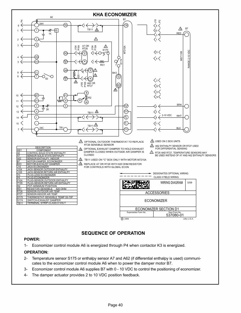
Page 40
KHA ECONOMIZER
SEQUENCE OF OPERATION
POWER:
1- Economizer control module A6 is energized through P4 when contactor K3 is energized.
OPERATION:
2- Temperature sensor S175 or enthalpy sensor A7 and A62 (if differential enthalpy is used) communi
cates to the economizer control module A6 when to power the damper motor B7.
3- Economizer control module A6 supplies B7 with 0 - 10 VDC to control the positioning of economizer.
4- The damper actuator provides 2 to 10 VDC position feedback.