kinematics analysis and numerical simulation … · kinematics analysis and numerical simulation of...
TRANSCRIPT

KINEMATICS ANALYSIS AND NUMERICALSIMULATION OF HYBRID
SERIAL-PARALLEL MANIPULATOR BASEDON NEURAL NETWORK
A. Rahmani, A. Ghanbari, M. Mahboubkhah
Abstract: This paper presents solution of kinematics analysis of a specific class ofserial-parallel manipulators, known as 2-(6UPS) manipulators, which are composedof several modules consisting of elementary manipulators with the parallel structureof the Stewart platform, by artificial neural network. At first, the kinematics modelof the hybrid manipulator is obtained. Then, as the inverse kinematics problem ofthis kind of manipulators is a very difficult problem to solve because of their highlynonlinear relations between joint variables and position and orientation of the endeffectors, a wavelet based neural network (wave-net) with its inherent learningability as a strong method was used to solve the inverse kinematics problem. Also,the proposed wavelet neural network (WNN) is applied to approximate the pathsof middle and upper plate in a circular and a spiral path, respectively. The resultsshow high accurate performance of the proposed WNN.
Key words: hybrid manipulators, kinematics analysis, network training, nonlinearsystem, wavelet neural network
Received: April 26, 2014 DOI: 10.14311/NNW.2015.25.022Revised and accepted: December 25, 2014
1. Introduction
A hybrid manipulation system is a sequence of parallel mechanisms which canovercome the limited workspace of parallel mechanism and can provide feature ofboth for serial and parallel mechanism. They are able to achieve high stiffnessand high force-to-weight ratio. The hybrid serial-parallel robotic manipulator hasattracted the attention of many researchers recently [19, 10, 7, 26], and it also hasgrowing applications to robotics, machine tools, positioning systems, measurementdevices, and so on. It has shown great potential and advantage both closed-loopand opened-loop manipulator over the traditional manipulator. Many differenttypes of hybrid robots have been investigated [22, 4, 3, 28]. Tanio [24] presented
Arash Rahmani – Corresponding author, Ahmad Ghanbari, Mehran Mahboubkhah, De-partment of Mechanical Engineering, University of Tabriz, Tabriz, ZIP Code: 51666-16471, Iran, Tel: +98 4136661496, E-mail: ara [email protected], [email protected],
c⃝CTU FTS 2015 427

Neural Network World 4/15, 427–442
a hybrid (parallel-serial) manipulator consisting of two serially connected parallelmechanisms and overall 6-DOF and gave its closed-form solution for forward andinverse position problems. Romdhane [23] investigated the hybrid manipulatorwhich was made of a base and two platforms in series and the motion of the midplatform is restricted only to three translations and the second platform rotatesspherically with respect to the mid platform using joint connected the mid platformand top platform. The characteristics of 6-DOF parallel–serial hybrid manipulatorswhich feature a 3-DOF in series actuated module mounted on the moving plate ofanother 3-DOF in parallel actuated manipulator with prismatic actuators is studiedin [13]. The kinematics of hybrid type manipulation system with 6-DOF, whichconsists of a 3-DOF planar parallel platform and a 3-DOF serial robot arm, isdiscussed by Yang et al. [25]. Huang et al. [14] studied a conceptual designand dimensional synthesis of a 3-DOF parallel mechanism module which forms themain body of a newly invented 5-DOF reconfigurable hybrid robot. LiangZhi etal. [17] studied a hybrid 5-DOF manipulator based on the novel 3-RPS inactuatedparallel manipulator. In their design a 2-DOF serial working table is placed overthe mobile platform. A new methodology to synthesize hybrid robots as a wholestructure is presented by Campos et al. [2]. Their method is based on Assuregroups as the simplest basic blocks to build kinematic chains. Gallardo et al. [8]studied kinematics and dynamics of 2-(3-RPS) manipulators by means of screwtheory and the principle of virtual work. A novel 3-RPS-3-SPR serial-parallelmanipulator (S-PM) with 6 degree of freedoms is proposed in [11] and its inversekinematics, active forces and workspace are solved. First, the inverse displacementis solved in close form based on the geometrical and the dimensional constraints.Then, Jacobian matrices are derived and the active forces are solved using theprinciple of virtual work. Gallardo et al. [9] address the kinematics, includingposition, velocity and acceleration analyses, of a modular spatial hyper-redundantmanipulator built with a variable number of serially connected identical mechanicalmodules with autonomous motions. Li et al. [16] used a hybrid manipulator as amulti-dimensional vibration isolator based on the parallel mechanism. The schemedesign, inverse kinematics, workspace and dexterity are carried out in their paper.Kizir et al. [15] used Kane transition function to generate several trajectories forcontrolling a high precision hybrid platform by a PID and sliding mode controller.Chen et al. [5] proposed a multi-objective genetic algorithm trajectory planner fora PKM, based on the dynamics approach. Parikh et al. [18] presented iterationneural network strategy for solution of forward kinematic of parallel mechanisms.
In this paper, a novel hybrid robot 2-(6-UPS) is introduced that comprises asequence of two identical Stewart mechanism modules. The serial form of thesehybrid manipulators overcomes the limited workspace of parallel manipulators andimproves overall stiffness and response characteristics. Then, kinematic model ofthe hybrid robot is presented and because highly nonlinear relations between jointvariables and position and orientation of the end effectors, wavelet neural networkhas been provided and used to solve the forward kinematics. In addition, theproposed WNN is applied to approximate the paths of mid and upper plate incircle and spiral path respectively.
428

Rahmani A., Ghanbari A., Mahboubkhah M.: Kinematics analysis and. . .
2. Description of the hybrid robot
The mechanism under investigation in this paper consists of two identical modules(base and upper modules) such that each module is Stewart Platform mechanismwith 6-DOFs. In this hybrid mechanism, we have three platforms and twelve pods.Base platform is stationary and connected to middle platform via 6 extensible pods.Also, middle platform is connected to upper platform (as an end effecter) via 6extensible pods. Each pod connects to the platform at its connection point througha spherical joint, and to the base at its connection point through universal joint.Each pod consists of two parts: the upper part and the lower part, which connectto each other through prismatic joint. Therefore, it is referred to as the 2-(6UPS)mechanism. This manipulator is actuated by motors located on the prismaticjoints. Fig. 1 shows the design of the mentioned hybrid robot and structure of themiddle and upper plates. Cartesian coordinate frame is attached to each plate withz axis normal to the plate.
3. Forward and inverse kinematics solution
Mechanism kinematics deals with the study of the mechanism motion as con-strained by the geometry of the links. Typically, the study of mechanism kine-matics is divided into two parts: inverse kinematics and direct kinematics. In theabout mentioned hybrid robot, the inverse kinematics problem involves mapping aknown pose (position and orientation) of the moving platforms of the mechanismto a length of each module’s pods. The direct kinematics problem involves themapping from a known length of each module’s pods to a pose of the moving plat-forms. In this section, the inverse and forward kinematics problems of proposedmechanism are described in closed form.
mY
mP
mP
mP
mP
mP
mP
mX
uX
uY
uP
uP
uP
uP
uP
uP
Fig. 1 Configuration of 2-(6-UPS) hybrid manipulator and plates.
The proposed kinematics model (vectorial kinematic analysis) using in this pa-per has some advantages compared to other methods:
429

Neural Network World 4/15, 427–442
a) This method provides a geometric description of rigid motion which greatlysimplifies the analysis of mechanism [21]. So, it is easily generalized to kine-matic analysis for most hybrid parallel-parallel, parallel-serial and serial-serialmanipulators.
b) This method suffers from singularity problems less than differential kinemat-ics based solution and it is useful and more applicable for work space analysis[20].
c) This method can be used easily for mechanism velocity mapping especiallyfor parallel and hybrid manipulators.
Fig. 2 shows the vectorial representation of the i-th pod at each module. Ac-cording to Fig. 2, the middle and upper moving platforms frame are shown by {Om}and {Ou}, respectively, and base frame with {Ob}. Also, (xm, ym, zm, θmx , θ
my , θ
mz )
and (xu, yu, zu, θux, θuy , θ
uz ) present the location (position and orientation) of the mid-
dle and upper moving platform respectively. Now, the inverse kinematics of eachmodule is obtained at first, and then forward kinematics is considered. The inversekinematic problem of the platforms involves determination of the linear position,of six Pods for each module through considering a specified position, of the middleand upper moving platforms center.
For each module, homogeneous transformation matrices from frame {Ou} toframe {Om} and frame {Om} to frame {Ob} are HOu,Om and HOm,Ob respectively,and are described as:
HOu,Om =
Ru
1 Ru4 Ru
7 xu
Ru2 Ru
5 Ru8 yy
Ru3 Ru
6 Ru9 zu
0 0 0 1
=
=
CθuzCθ
uy −SθuzCθux + CθuzSθ
uySθ
ux SθuzSθ
ux + CθuzSθ
uyCθ
ux xu
SθuzCθuy CθuzCθ
ux + SθuzSθ
uySθ
ux −CθuzSθux + SθuzSθ
uyCθ
ux yy
−Sθuy CθuySθux CθuyCθ
ux zu
0 0 0 1
,(1)
HOm,Ob =
Rm
1 Rm4 Ru
7 xm
Rm2 Rm
5 Ru8 ym
Rm3 Rm
6 Ru9 zm
0 0 0 1
=
=
Cθmz Cθ
my −Sθmz Cθmx + Cθmz Sθ
my Sθ
mx Sθmz Sθ
mx + Cθmz Sθ
my Cθ
mx xm
Sθmz Cθmy Cθmz Cθ
mx + Sθmz Sθ
my Sθ
mx −Cθmz Sθmx + Sθmz Sθ
my Cθ
mx ym
−Sθmy Cθmy Sθmx Cθmy Cθ
mx zm
0 0 0 1
,(2)
where Cθ = cos(θ) , Sθ = sin(θ) .
Beside, Om
Lui and Ob
Lui are the vectors of length of the i-th pod in upper module
relative to Om and Ob frame respectively. And, Ob
Lbi is the vector of length of
430

Rahmani A., Ghanbari A., Mahboubkhah M.: Kinematics analysis and. . .
x
y
z
b
m
u
u
i
u
m
u
iL
b
iL
i
Upper Module
Base Module
m
i
Fig. 2 Vectorial representation of the i-th pod at each module.
the i-th pod in base module relative to Ob frame. Vector of length of the i-th podwithout considering modules and frames, is a 1× 4 vector which is described as
Li = (Lix,Liy,Liz, 1). (3)
Also, bi, Pmi ,P
ui are the six vertices of the base, middle and upper plates relative
to Ob,Om and Ou frame respectively:
bi = (bix, biy, 0, 1) i = 1, 2 , . . . , 6, (4)
Pmi = (pmi x, p
mi y, 0, 1) i = 1, 2 , . . . , 6, (5)
Pui = (pui x, p
ui y, 0, 1) i = 1, 2 , . . . , 6. (6)
Now, according to transformation of a vector from one frame to another, we
can determine Ob
Lbi ,
Om
Lui and Ob
Lui as
Ob
Lbi = (HOm, ObPm
i − bi), (7)
431

Neural Network World 4/15, 427–442
Om
Lui = (HOu, OmPu
i −Pmi ), (8)
Ob
Lui = HOm, Ob
Om
Lui = HOm, Ob(HOu, OmPu
i −Pmi ). (9)
Scalar form of each pod’s length for each module is as
lui =∥∥∥Ob
Lui
∥∥∥ =√
ObLuix + ObLu
iy +ObLu
iz i = 1, . . . , 6, (10)
lbi =∥∥∥Ob
Lbi
∥∥∥ =√
ObLbix + ObLb
iy +ObLb
iz i = 1, . . . , 6. (11)
Eqs. (7) and (9) define the length of pods of each module relative to base in aclosed form as a vector. Mapping the pose of middle and upper plates to the lengthof pods is easy and straightforward. But, because of highly nonlinear characteristicof these equations, the mapping from a known length of each module’s pods to apose of the moving platforms is rather difficult and too complicated. Therefore,wavelet based neural network (wave-net) is applied to solve forward kinematicsof this mechanism. As it will be seen in the next, we use length of each pod ofeach module (Eqs. (10) and (11)) as input data for training the proposed neuralnetwork.
4. Wavelet neural network
4.1 Structure of network
The wavelet neural network (WNN) is the model based on wavelet transformationand artificial neural network [27]. Due to wavelet transform, it has good localizationcharacteristics in time and frequency domain and neural networks have good abilityto approximate complicated maps, WNN incorporate the good learning abilityand the good property of localization, which have been successfully applied infunction approximation and pattern classification. A neural network is constructedby interconnecting a number of neurons so as to form a network in which allconnections are made in the forward direction.
Since the approximation class is nonlinear in the adjustable parameters, thetraining procedure of the neural networks may become trapped in some local min-imum depending on the initialization. To overcome this problem, the wavelet net-works have been proposed as an alternative to neural networks, which follow theavailability of rates of convergence for approximation by wavelet based networks.
In this section, a feed-forward single hidden layer network is introduced. Fora (back propagation) BP neural network with only one hidden layer of neurons,using basis wavelets as it’s activate functions of hidden layer, we get a multi-inputand multi-output wavelet neural networks in Fig. 3.
This WNN has m, p, n nodes in the input layer, hidden layer and output layer,respectively. And the activate function of the j-th node in the hidden layer is [1]
ψaj ,bj (t) =1
√ajψ(t− bjaj
) j = 1, 2, . . . , p, (12)
where ψ(t) is the mother wavelet function which is localized both in time andfrequency and could be chosen as a different function according to the feature of
432

Rahmani A., Ghanbari A., Mahboubkhah M.: Kinematics analysis and. . .
the problem. Fig. 4 shows four types of most applicable wavelet functions. In thispaper we use the Mexican Hat wavelet. This wavelet is derived from a function,which is proportional to the second derivative of the Gaussian probability densityfunction. It is non-orthogonal, with infinite support and has maximum energyaround origin with a narrow band. The expression for the Mexican Hat wavelet isgiven by Eq. (13). In this paper, f(t) is chosen as sigmoid function:
ψ(t) = (1− 2t2) · exp(−t2). (13)
Fig. 3 Structure of WNN.
The wavelet neural network parameters in Fig. 3, (W (1),W (2),Θ(1),Θ(2), a1, . . . ,ap, b1, . . . , bp), should be adjusted through training.
4.2 Training of network
Back propagation method is the most frequently used technique for training a feedforward network. It involves two passes through the network, a forward pass and abackward pass. The forward pass generates the network’s output activities and thebackward pass involves propagating the error initially found in the output nodesback through the network to assign errors to each node that contributed to theinitial error. Once all the errors are assigned, the weights are changed so as tominimize these errors. Since the WNN in Fig. 3 is derived from a feed forwardneural network, we use back propagation method to train this network. For theWNN in Fig. 3, when the input vector is X = (xk) = (x1, x2, . . . , xm), we get theoutput of the j-th node in hidden layer:
ψaj ,bj
(m∑
k=1
w(1)jk xk − θ
(1)j
)= ψaj ,bj
(F
(1)j
)=
1√ajψ
(F
(1)j − bj
aj
), (14)
433

Neural Network World 4/15, 427–442
Fig. 4 Wavelet functions.
where
F(1)j =
m∑k=1
(w
(1)jk xk − θ
(1)j
). (15)
In this research, m = 6 for each module and X = (xk) = (x1, x2, . . . , x6) =(l1, l2, . . . , l6).
The output of the i-th node of output layer is:
yi = f
p∑j=1
w(2)ij ψaj,bj(F
(1)j )− θ
(2)i
= f(F(2)i ), (16)
where
F(2)i =
p∑j=1
(w
(2)ij ψaj,bj(F
(1)j )− θ
(2)i
). (17)
From Eq. (14) we get the output vector of the WNN:Y = (y1, y2, . . . , yn), whichhere is (x, y, z, α, β, γ) for each module. Suppose we have Q training samples. Foreach sample q, the desired output vector is Yq = (yq1, yq2, . . . , yqn), the outputvector of the WNN is Yq = (yq1, yq2, . . . , yqn). With these Q training samples, wetrain the WNN through batch learning process. Then the main goal of the networkis to minimize the total error E of each output node i over all training samples[12]:
E =1
2
Q∑q=1
n∑i=1
(yqi − yqi)2. (18)
434

Rahmani A., Ghanbari A., Mahboubkhah M.: Kinematics analysis and. . .
By the iterative gradient descent method, the parameters of the wavelet neuralnetwork can be formulated by
w(2)ij (t+ 1) = (1 + β)w
(2)ij (t)− β w
(2)ij (t− 1)− λ
∂E
∂w(2)ij
, (19)
w(1)jk (t+ 1) = (1 + β)w
(1)jk (t)− β w
(1)jk (t− 1)− λ
∂E
∂w(1)jk
, (20)
θ(2)i (t+ 1) = (1 + β)θ
(2)i (t)− β θ
(2)i (t− 1)− λ
∂E
∂θ(2)i
, (21)
θ(1)j (t+ 1) = (1 + β)θ
(1)j (t)− β θ
(1)j (t− 1)− λ
∂E
∂θ(1)j
, (22)
aj(t+ 1) = (1 + β)aj(t)− β aj(t− 1)− λ∂E
∂aj, (23)
bj(t+ 1) = (1 + β)bj(t)− β bj(t− 1)− λ∂E
∂bj, (24)
where t is the iteration index of learning and λ is the learning rate. To improve therate of learning, we modify the original learning rule with the momentum factorβ (0 < β < 1) to the weights [6]. The partial derivatives of the error E with respectto each parameter can be calculated easily.
5. WNN solution for kinematics of robot
In order to model forward kinematics of hybrid robot with wave-net according tostructure of robot, we have modeled the base module and the upper one, respec-tively. The input data of the network are the length of pods for each moduleaccording to Eqs. (9) and (10). At first and before proposing neural network, us-ing inverse kinematics (mapping position and orientation of center point of midand upper plate to length of pods), we generate some data for training the net-works. Then the length of pods of the base module, Lb = (lb1 , l
b2 , l
b3 , l
b4 , l
b5 , l
b6),
is fed to the network to define the position and orientation of the middle plate,Pm = (xm, ym, zm, αm, βm, γm). Repeating same steps as described in below, leadsus to solving forward kinematics of upper module, too. For this, using the length ofpods of the upper module, Lu = (lu1 , l
u2 , l
u3 , l
u4 , l
u5 , l
u6), and the position and orien-
tation of the middle plate, Pm = (xm, ym, zm, αm, βm, γm), we calculated the posi-tion and orientation of the upper plate (end effecter), Pu = (xu, yu, zu, αu, βu, γu).Therefore, we have two different networks.
The algorithm of the wavelet neural network for approximating the kinematicsof hybrid robot for each module is summarized as follows:
Step 1: Set the initial values of networks parameters (W (1),W (2),Θ(1),Θ(2), a1,. . . , ap, b1, . . . , bp), learning rate λ and momentum factor β.
435

Neural Network World 4/15, 427–442
Step 2: Input the training data and the desired output values. Give input vectorsX = (x1, x2, . . . , xm) where it is the length of pods of each module and a desiredoutput vector Yq = (yq1, yq2, . . . , yqn), the theoretical values acquired from inversekinematic solution of Eqs. (7) and (9).
Step 3: For each input datum, calculate the output of the wavelet neural networkby Eq. (16).
Step 4: Adjust the networks parameters (W (1),W (2),Θ(1),Θ(2), a1, . . . , ap, b1, . . . ,bp) using gradient descent algorithm by Eqs. (19) to (24).
Step 5: The error function E is calculated by Eq. (18). If the error is less than thedesired bound, the networks parameters are obtained and the learning process isterminated, else go to step 2.
6. Results
In this section, we present the results of the proposed WNN on approximating thekinematic analysis of hybrid robot. The architecture used for the wavelet networkwas one input layer with six neurons, one hidden layer with 153 neurons and oneoutput layer with six neurons. The network was trained with a learning rate of0.15, a momentum term of 0.05, and 2,048 learning iterations. The largest error Eor given precision is 0.5%. Tab. I shows sample results of direct kinematics withreference length of pods (L0 = 550mm) and pods length variation of base moduleand upper module:
Lbase = (l1 = 240mm, l2 = 50mm, l3 = 110mm, l4 = 190mm, l5 = 230mm,
l6 = 300mm),
Lupper = (l1 = 210mm, l2 = 140mm, l3 = 290mm, l4 = 260mm, l5 = 120mm,
l6 = 40mm).
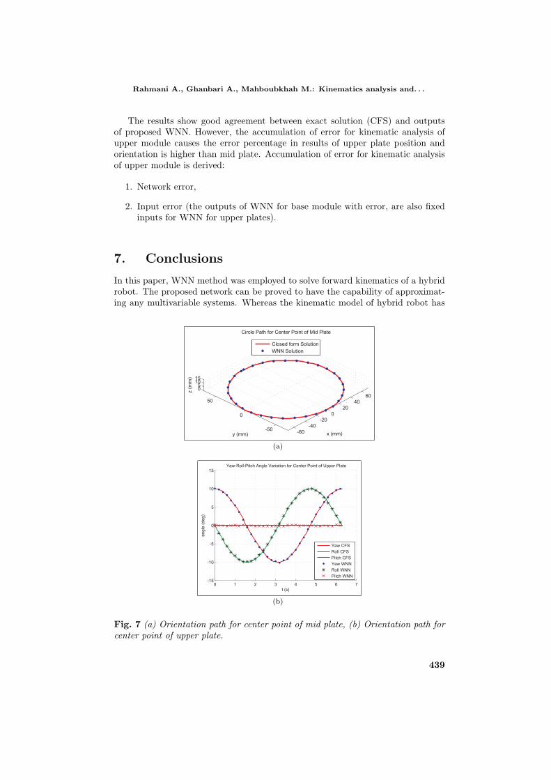
And a comparison of WNN with closed form solutions (CFS) is given there.Also, Figs. 5 to 8 show the results of the proposed WNN for the specific paths
of middle and upper plates of hybrid robot. Results given here are for circle pathand spiral path with elliptical base curve for center point of middle and upperplate, respectively. Using inverse kinematic analysis for proposed paths of plates,we define motions of each pod of each module (Fig. 5). Then, we feed the proposedWNN by the pods motions to get the paths of plates. Fig. 6 shows the positionpaths and Fig. 7 shows orientation paths for center point of each plate. Again,we used the outputs of the proposed WNN for inverse kinematic analysis to definethe new motions of each pod of each module and compared them with the podsmotions which results from CFS. Fig. 8 show the results, for variation of length ofeach pods of base and upper module for circle path for center point of mid platewith (10×[− cos t◦, sin t◦, 0◦]) orientation and spiral path with elliptical base curvefor center point of upper plate with (10× [cos t◦, − sin t◦, 0◦]) orientation.
436

Rahmani A., Ghanbari A., Mahboubkhah M.: Kinematics analysis and. . .
Base
Module
(L1=
240mm,L2=
50mm,L3=
110mm,L4=
190mm,L5=
230mm,L6=
300mm)
mid
Plt.
x[m
m]
y[m
m]
z[m
m]
α[deg]
β[deg]
γ[deg]
CFS
WNN
CFS
WNN
CFS
WNN
CFS
WNN
CFS
WNN
CFS
WNN
28.972
29.015
48.009
48.143
62.768
62.542
−12.612
−12.636
12.329
12.367
0.79
60.79
4
Err
[%]
0.15
0.28
−0.36
0.19
0.31
−0.27
UpperM
odule
(L1=
210mm,L2=
140mm,L3=
290mm,L4=
260mm,L5=
120mm,L6=
40mm)
upperPlt.
x[m
m]
y[m
m]
z[m
m]
α[deg]
β[deg]
γ[deg]
CFS
WNN
CFS
WNN
CFS
WNN
CFS
WNN
CFS
WNN
CFS
WNN
63.537
63.823
51.997
51.794
78.259
77.883
15.254
15.309
-2.732
-2.745
8.09
88.07
0
Err
[%]
0.45
−0.39
−0.48
0.36
0.48
0.34
Tab.IResultsofCFSandWNN
forasample
case
ofeach
podslengthvariationforeach
module.
437

Neural Network World 4/15, 427–442
0 1 2 3 4 5 660
80
100
120
140
160
180
200
220
Time (s)
Variation o
f p
ods L
ength
(m
m)
Variation of pods Length of Base Module for Circle Path
1st pod
2nd pod
3th pod
4th pod
5th pod
6th pod
(a)
0 1 2 3 4 5 60
50
100
150
200
250
300
Time (s)
Variation o
f p
ods L
ength
(m
m)
Variation of pods Length of Upper Module for Spiral Path
1st pod
2nd pod
3th pod
4th pod
5th pod
6th pod
(b)
Fig. 5 (a) Variation of length of pods of base module for circle path with orientation(10× [− cos t◦, sin t◦, 0◦]), (b) Variation of length of pods of upper module for spiralpath with orientation (10× [cos t◦, − sin t◦, 0◦]).
-60
-40
-20
0
20
40
60
-50
0
50
05
1015
z (
mm
)
Circle Path for Center Point of Mid Plate
y (mm) x (mm)
Closed form Solution
WNN Solution
(a)
-40-20
020
40-50
0
50
0
20
40
60
x (mm)
Spiral Path for Center Point of Upper Plate
y (mm)
z (
mm
)
Closed form Solution
WNN Solution
(b)
Fig. 6 (a) Circle path for center point of mid plate with orientation (10 ×[− cos t◦, sin t◦, 0◦]), (b) Spiral path for center point of upper plate with orientation(10× [cos t◦, − sin t◦, 0◦]).
438
Rahmani A., Ghanbari A., Mahboubkhah M.: Kinematics analysis and. . .
The results show good agreement between exact solution (CFS) and outputsof proposed WNN. However, the accumulation of error for kinematic analysis ofupper module causes the error percentage in results of upper plate position andorientation is higher than mid plate. Accumulation of error for kinematic analysisof upper module is derived:
1. Network error,
2. Input error (the outputs of WNN for base module with error, are also fixedinputs for WNN for upper plates).
7. Conclusions
In this paper, WNN method was employed to solve forward kinematics of a hybridrobot. The proposed network can be proved to have the capability of approximat-ing any multivariable systems. Whereas the kinematic model of hybrid robot has
-60
-40
-20
0
20
40
60
-50
0
50
05
1015
z (
mm
)
Circle Path for Center Point of Mid Plate
y (mm) x (mm)
Closed form Solution
WNN Solution
(a)
0 1 2 3 4 5 6 7-15
-10
-5
0
5
10
15
t (s)
angle
(deg)
Yaw-Roll-Pitch Angle Variation for Center Point of Upper Plate
Yaw CFS
Roll CFS
Pitch CFS
Yaw WNN
Roll WNN
Pitch WNN
(b)
Fig. 7 (a) Orientation path for center point of mid plate, (b) Orientation path forcenter point of upper plate.
439

Neural Network World 4/15, 427–442
(a) (b)
(c) (d)
(e) (f)
Fig. 8 (a)–(f) Length variation of pods of base and upper module for circle andspiral path respectively with defined orientation change.
440

Rahmani A., Ghanbari A., Mahboubkhah M.: Kinematics analysis and. . .
strongly nonlinear characteristic, the network can not only be trained in a shorttime, but also shows better performance in solving problems. According to theresults, there is good agreement between WNN and CFS, but, because of accumu-lation of error, the error of results of upper plate is larger than the error of the midplate. Nevertheless, according networks tanning approach the maximum error forall cases is less than 0.5%.
References
[1] BANAKAR A., AZEEM M.F. Artificial wavelet neuro-fuzzy model based on parallel waveletnetwork and neural network. Soft Computing. 2008, 12(8), pp. 789–808, doi:10.1007/s00500-007-0238-z.
[2] CAMPOS A., BUDDE C., HESSELBACH J. A type synthesis method for hybridrobot structures. Mechanism and Machine Theory. 2008, 43(8), pp. 984–995, doi:10.1016/j.mechmachtheory.2007.07.006.
[3] CARBONE G., CECCARELLI M. A stiffness analysis for a hybrid parallel-serial manipula-tor. Robotica. 2004, 22(5), pp. 567–576, doi: 10.1017/S0263574704000323.
[4] CARBONE G., CECCARELLI M. A serial-parallel robotic architecture for surgical tasks.Robotica. 2005, 23(3), pp. 345–354, doi: 10.1017/S0263574704000967.
[5] CHEN C.-T., PHAM H.-V. Trajectory planning in parallel kinematic manipulators using aconstrained multi-objective evolutionary algorithm. Nonlinear Dynamics. 2012, 67(2), pp.1669–1681, doi: 10.1007/s11071-011-0095-2.
[6] CHEN D., HAN J. Application of wavelet neural network in signal processing of MEMSaccelerometers. Microsystem technologies. 2011, 17(1), pp. 1–5, doi:10.1007/s00542-010-1169-7.
[7] COPPOLA G., ZHANG D., LIU K. A 6-DOF reconfigurable hybrid parallel manipu-lator. Robotics and Computer-Integrated Manufacturing. 2014, 30(2), pp. 99–106, doi:10.1016/j.rcim.2013.09.011.
[8] GALLARDO-ALVARADO J., AGUILAR-NAJERAA C.R., CASIQUE-ROSASA L., RICO-
MARTINEZ J.M., ISLAM N. Kinematics and dynamics of 2 (3-RPS) manipulators by meansof screw theory and the principle of virtual work. Mechanism and Machine Theory. 2008,43(10), pp. 1281–1294, doi: 10.1016/j.mechmachtheory.2007.10.009.
[9] GALLARDO J., LESSO R., RICO J.M., ALICI G. The kinematics of modular spatial hyper-redundant manipulators formed from RPS-type limbs. Robotics and Autonomous Systems.2011, 59(1), pp. 12–21, doi: 10.1016/j.robot.2010.09.005.
[10] HU B. Formulation of unified Jacobian for serial-parallel manipulators.Robotics and Computer-Integrated Manufacturing. 2014, 30(5), pp. 460–467,doi: 10.1016/j.rcim.2014.03.001.
[11] HU B., HU B., LU Y., YU J.J., ZHUANG S. Analyses of Inverse Kinematics, Statics andWorkspace of a Novel 3RPS-3SPR Serial-Parallel Manipulator. The Open Mechanical Engi-neering Journal. 2012, 5, pp. 65–72, doi: 10.2174/1874155X01206010065.
[12] HUANG M., CUI B. A novel learning algorithm for wavelet neural networks. Advances inNatural Computation. 2005, Springer, pp. 1–7, doi: 10.1007/11539087 1.
[13] HUANG M.Z., LING S.-H., SHENG Y. A study of velocity kinematics for hybrid ma-nipulators with parallel-series configurations. In: Proceedings of the IEEE InternationalConference on Robotics and Automation, Atlanta, GA. IEEE, 1993, 1, pp. 456 - 461, doi:10.1109/ROBOT.1993.292022.d.
[14] HUANG T., LI M., ZHAO X.M., MEI J.P., CHETWYND D.G., HU S.J. Conceptual de-sign and dimensional synthesis for a 3-DOF module of the TriVariant-a novel 5-DOF re-configurable hybrid robot. IEEE Transactions on Robotics. 2005, 21(3), pp. 449–456, doi:10.1109/TRO.2004.840908.
441

Neural Network World 4/15, 427–442
[15] KIZIR S., BINGUL Z. Position Control and Trajectory Tracking of the Stewart Platform.In: S. KUCUK, ed. Serial and Parallel Robot Manipulators – Kinematics, Dynamics, Controland Optimization. Rijeka: InTech, 2012, pp. 179–202, doi: 10.5772/35569.
[16] LI B., ZHAO W., DENG Z. Modeling and analysis of a multi-dimensional vibration isolatorbased on the parallel mechanism. Journal of Manufacturing Systems. 2012, 31(1), pp. 50–58,doi: 10.1016/j.jmsy.2010.12.001.
[17] LIANGZHI F., ELATTA A., XIAOPING L. Kinematic calibration for a hybrid 5-DOF ma-nipulator based on 3-RPS in-actuated parallel manipulator. The International Journal ofAdvanced Manufacturing Technology. 2005, 25(7–8), pp. 730–734, doi:10.1007/s00170-003-1987-1.
[18] PARIKH P.J., LAM S.S. Solving the forward kinematics problem in parallel manipulatorsusing an iterative artificial neural network strategy. The International Journal of AdvancedManufacturing Technology. 2009, 40(5–6), pp. 595–606, doi: 10.1007/s00170-007-1360-x.
[19] PISLA D., GHERMAN B., VAIDA C., SUCIU M., PLITEA, N. An active hybrid paral-lel robot for minimally invasive surgery. Robotics and Computer-Integrated Manufacturing.2013, 29(4), pp. 203–221, doi:10.1016/j.rcim.2012.12.004.
[20] QAZANI M.R.C., PEDRAMMEHR S., RAHMANI A., DANAEI B., ETTEFAGH M.M.,RAJAB A.K.S., ABDI H. Kinematic analysis and workspace determination of hexarot-anovel 6-DOF parallel manipulator with a rotation-symmetric arm system. Robotica. pp. 1–18, doi: 10.1017/S0263574714000988.
[21] QAZANI M.R.C., PEDRAMMEHR S., RAHMANI A., SHAHRYARI M., RAJAB A.K.S.,ETTEFAGH M.M. An experimental study on motion error of hexarot parallel manipulator.The International Journal of Advanced Manufacturing Technology. 2014, 72(9–12), pp. 1361–1376, doi: 10.1007/s00170-014-5685-y.
[22] RICO J., GALLARDO J., DUFFY J. Screw theory and higher order kinematic analysis ofopen serial and closed chains. Mechanism and Machine Theory. 1999, 34(4), pp. 559–586,doi: 10.1016/S0094-114X(98)00029-9.
[23] ROMDHANE L. Design and analysis of a hybrid serial-parallel manipulator. Mechanism andMachine Theory. 1999, 34(7), pp. 1037–1055, doi: 10.1016/S0094-114X(98)00079-2.
[24] TANEV T.K. Kinematics of a hybrid (parallel–serial) robot manipulator. Mechanism andMachine Theory. 2000, 35(9), pp. 1183–1196, doi: 10.1016/S0094-114X(99)00073-7.
[25] YANG G., CHENW., HO E.H.L. Design and kinematic analysis of a modular hybrid parallel-serial manipulator. In: Proceedings of the 7th International Conference on Control, Automa-tion, Robotics and Vision (ICARCV 2002), Marina Mandarin, Singapore. IEEE, 2002, 1,pp. 45–50, doi: 10.1109/ICARCV.2002.1234788.
[26] ZENG Q., EHMANN K.F. Design of parallel hybrid-loop manipulators with kinema-totropic property and deployability. Mechanism and Machine Theory. 2014, 71, pp. 1–26,doi: 10.1016/j.mechmachtheory.2013.08.017.
[27] ZHANG Q., BENVENISTE A. Wavelet networks. IEEE Transactions on Neural Networks.1992, 3(6), pp. 889–898.
[28] ZHOU B., XU Y. Robust control of a 3-DOF hybrid robot manipulator. The Interna-tional Journal of Advanced Manufacturing Technology. 2007, 33(5–6), pp. 604–613, doi:10.1007/s00170-006-0474-x.
442