king fahd university of petroleum & …faculty.kfupm.edu.sa/ee/samir/summer training/ahmad...
TRANSCRIPT
SUMMER TRAINING REPORT
KING FAHD UNIVERSITY OF PETROLEUM &
MINERALS
COLLEGE OF SCIENCE ENGINEERING
ELECTRICAL ENGINEERING DEPARTMENT
Summer Training Report
by
Ahmed ALgahtani
200651040
Advisor
Dr. Ahmed Yamani

SUMMER TRAINING REPORT
INTRODUCTION:
The college of science engineering gives a chance to their students to
spend 8 weeks in industrial companies. This training gives the student the
opportunity to see what they studied and how to deal with practical live. My
training program was in the period from 3 July 2010 to 25 Augusta 2010 at
Saudi Electricity Company – Eastern Region Branch (SEC-ERB).
During my summer training I worked in Operation Areas (Distribution
System) in Customer Services Office. I attended in the medium voltage which
are the Maintenance, Operation, Engineering, and Planning and Construction
Division. The planning and construction division was a good start which I
spent the most of period of my training with them.
The Planning and Construction Division deals with the power supply and
the system improvement. Also, this division is responsible for providing bulk
customers with relay settings for their switchgears.
The Engineering Division deals with the distribution of substations and
mini pillars among a new region. This includes also the exemption from a
substation or a mini pillar when customers objecting to have a substation or a
mini pillar to be funded in their lots.
The Maintenance Division concerns maintaining some of electrical
equipment in the medium voltage. It deals with substations and their contents
like transformers, ring main units/ switchgears, and low voltage panels. This
includes checking the fuses of the ring main units, oil level in oil switches, and
SF6 gas level in SF6 switches.
The Operation Division concerns maintaining mini pillars, shutdown
operations, and breakers readings. Moreover, it deals with cable faults
comprehensively and there are a special department for it having special
equipment and cars concerning cable faults.

SUMMER TRAINING REPORT
DIVISIONS OF SEC ACCORDING TO THE POWER:
Power Planet (Generation System):
Energy is converted at the generating station from one of its basic
forms, such as fossil fuels, hydro, and nuclear into electric energy. Power
plants generate electricity to switching stations where step up
transformers are located to raise the voltage to transmission levels.
Power Transmission:
This is the part of the system that transfers generated electricity
from the power plants to the main supply points throughout the eastern
province by using transmission lines which are the connecting links
between the generating stations and the distribution systems.
The transmission network consists of:
1. Transmission lines: 69KV, 1155KV, 230KV, and 380KV.
2. Switching stations: Bulk supply points (B.S.P.) and Grid Stations.
The Grid Station receives 69KV and steps it down to 13.8 KV and
the Grid Station is the final link in the transmission network.
Operation Areas (Distribution System).
The objective of Power Distribution System is to deliver the Electrical
power to Customers in safe, reliable and most economical way. This means
that a Customer receives a supply of Electrical power required by him at the
time and place at which he can use it. Several parameters of an Electricity
supply such as frequency, continuity of supply, voltage level, etc. should be
within allowable limits to ensure that the Customer obtains satisfactory
performance for his electrical equipment while ensuring that the demands of
the Customers continue to be met, the capital and operating costs of doing so
should be reduced minimum as possible.

SUMMER TRAINING REPORT
1.BACKGROUND:
Fig.1.1 shows the transmission of power starting from the power planet until
reaching the customer. The power transmission starts from the power plant by
providing a standard voltage of 13.8 KV. After that, the 13.8 KV is converted
to 230 KV and 380 KV using step up transformers in the bulk supply point.
The 230 KV is used in the near cities whereas the 380 KV is provided if
necessary to be transmitted to far cities. This means that the 230 KV most exist
in each bulk supply point. After the transmission, the 230 KV is then converted
to 69 KV using step down transformers. In the grid station, the 69 KV is
converted to 13.8 KV and in turn it is transmitted to substations through
Breakers. The substation has a transformer which converts the 13.8KV to low
voltages of 220V/380V or 127V/220V. The low voltage is distributed from the
low voltage panel. Finally, the low voltage is delivered to the customer by
using a mini pillar.
Fig.1.1
SUMMER TRAINING REPORT
2. MEDIUM VOLTAGE UNTIL LOW VOLTAGE The medium voltage (13.8 KV) starts from the grid station (G/S) in which
it has a number of breakers (B) that depend on the transformers used in the grid
station. The feeders/cables that are coming from the breakers are of 13.8 KV
and distributed in the company network. This 13.8 KV is distributed to
substations in which they have step down transformers. The low voltage starts
just after the transformer in the substation. The substation uses a step down
transformer that transform the 13.8 KV to low voltages. In the next sections, it
is important to mention the 13.8 KV/ medium voltage electrical equipment in
which it starts from the substation, through the low voltage panel, mini pillars,
and until reaching meters.
2.1 Substations Substation (S/S) is formed by the ring main unit, transformer, the
low voltage panel, and the earth fault indicator. The transformer output
voltage is distributed through the low voltage panel. There is an indoor
substation, an outdoor substation and the pole mounted transformer
substation. The three differ from another in their appearance not in how
they are composed of. The indoor substation is a locked substation inside
a room whereas the outdoor substation is a locked substation that is out in
the open, and the pole mounted transformer substation is a substation that
has the transformer hanged in two poles. There is another type of
substations which is the street light substation where the company has no
relationship with maintaining the substation because it is owned by the
municipality. Fig2.1 shows the four types of substations with their
transformers and low voltage panels. The substation is named by the
transformer used on it, i.e. when the transformer used in the substation is
300 KVA transformer; the name of the substation is a 300 KVA 5
substation. Also, when the transformer is packed with the low voltage
panel, the substation is called a unit substation.

SUMMER TRAINING REPORT
2.1.1 Ring Main Unit The ring main unit (RMU) is a switchgear that takes the 13.8
KV cable, links it to the transformer in the substation, and also links
the 13.8 KV cable to another substation. This means that the ring
main unit has an incoming 13.8 KV cable, an outgoing 13.8 KV
cable, and a local cable. The incoming cable is a cable linked to the
substation by another substation whereas the outgoing cable is a
cable linked from the substation to another substation. The local
cable is used by the substation from the incoming cable. There are
two types of switchgears used at the company network. They differ
in the used insulation substances which are the oil switch, and the
Sulfur Hexafluoride (SF6) switch. Fig2.2. shows the two types of
switchgears including the substance level in each one. The most
popular one used in the company network is the oil switch even
though that the SF6 is better in insulation and the insulation
substance last more than 6 that in the oil switch. But, the SF6 switch
cheats operators who are responsible of the inspection because the
SF6 gas shrinks at winter and the operators who check the gas level
do not know whether the gas level is actually low or because of the
cold weather.

SUMMER TRAINING REPORT
There is an automatic change over switch which is another
type of oil switch shown in Fig2.3 that has three input feeders and
one output feeder. This switch is used for high class of customers
because when one feeder is damaged, it is automatically and very
fast changes to another feeder.

SUMMER TRAINING REPORT
Also, there is another type of oil switch used to change a
feeder locus. This switch has an input feeder and an output of one,
two, or three feeders. If there is multi number of oil switches that
are linked together by bus caps, they all have a single number, i.e.
three oil switches using one as an input and the others as outputs are
known as an oil switch with three legs. Fig.2.4 shows three oil
switches, i.e. an oil switch with three legs that has one input feeder
and two output ones. There is also another type of switches called a
load break switch used for high class of customers. The job of this
switchgear is the same as the automatic change over switch except
that the locus of a feeder is changed manually.
2.1.2 Transformers The transformers in the company underground network are of
four types which are the 300 KVA, 500 KVA, 1000 KVA, and the
1500 KVA transformer. All these transformers transform the 13.8
KV to their nominal KVA. Fig.2.5 shows a transformer in an
outdoor substation.

SUMMER TRAINING REPORT
The input for the substation is the 13.8 KV where it is of three
phases and Δ- configuration. When the 13.8 KV come to the
transformer through the RMU/switchgear, it is transformed to the
nominal KVA and the output will be in Y-configuration. As
mentioned earlier that the company uses transformers that differ in
their output KVA. Each transformer has a different output number
of cables and the output cables are of three phase which are; the red,
yellow, and the blue in addition to the neutral which is the black
cable. table2.1 gives the transformers' number of output cables and
the description of them.
Table2.1: Output cables of the SEC transformers for the 127V/220V low voltage.
Transformer LVP Output
cables / circuits Description
300 KVA 4 One 3 phase & one neutral
300 KVA 8 Two 3 phase & two neutrals
300 KVA 12 Three 3 phase & three neutrals
300 KVA 16 Four 3 phase & four neutrals
Moreover, there is an auxiliary transformer that is used inside
the grid station to energize the equipment used there like the air
conditioners, lamps, and any other necessary equipment. The
auxiliary transformer is energized from an existing breaker in the
grid station.
2.1.3 Low Voltage Panel The low voltage panel (LVP) is a panel that distributes the
output cables/circuits of the transformer. Each circuit from the low
voltage panel contains the red phase, yellow, and the blue phase in
addition to the neutral cable which is black. The low voltage panel
output number of circuits depends on the transformer used in the
substation. The transformer output cables are connected to the bus
bar of the low voltage panel and from the bus bar, the low voltage
circuits are provided such that each circuit has a circuit breaker of
400A for each phase in the circuit. This means that the maximum
amperage that a circuit from the low voltage panel withstands is
400A and beyond this current the cable may be damaged. Fig.2.6.
shows a low voltage panel including the bus bars and the output

SUMMER TRAINING REPORT
circuits without showing the circuit breakers because they are
covered.
2.1.4 Earth Fault Indicator The earth fault indicator (EFI) is used in every substation
because it indicates that the ring main unit is not energized and
declares that there is a cable fault. Fig 2.7 shows the EFI when the
substation is under normal condition and when the substation is not
energized.

SUMMER TRAINING REPORT
When the substation is not energized, the locus of the
incoming feeder is having a cable fault. The cable fault is not
necessary just before the substation and of course will not be after.
When the EFI indicates a fault, operators check the single line
diagram to indentify the substations in the feeder locus and go back
to check each substation in the locus one by one. When, a substation
in the locus does not declare a fault, the fault must be between the
one that does not declare and the other one that declares a fault.
2.2 Mini Pillars The mini pillar (MP) is a panel that takes one cable/circuit from the
low voltage panel and provides at most six circuits to divide them among
at most six customers. Fig.2.8 shows a mini pillar which has five circuits
and two bus bars. One bus bar is used as an input whereas the other one is
used if necessary to be connected to another mini pillar. The circuit
breakers of the mini pillars are of 200 A for each phase in a circuit.
Sometimes one customer needs two circuits from the mini pillar also
when customers need higher ampere, a circuit from the low voltage panel
is provided without using the mini pillar. There are at most two mini
pillars that can be connected together and there is two phase and one
neutral cables in each circuit, that are connected from the mini pillar to a
meter because each customer needs this specification to be energized in
the low voltage.

SUMMER TRAINING REPORT
2.3 Meters Meters are the SEC interface with customers. There are two types of
meters for low voltage customers, one is the regular meter and the other
is the service box shown in Fig.2.9. The regular meter and the service box
give the electrical consuming in kilowatt hour (KWH). The regular meter
circuit breakers range from 30A to 160A. When dealing with higher than
that, a service box meter is used up to 400A. The service box contains a
current transformer that transforms the high current that is impossible to
be read by the regular meter, into a low current in which the meter can
read without being damaged. Also, each service box has a multiplying
factor where the operator takes the reading from the meter and multiplies
it by the multiplying factor to give the actual reading.
For high voltage customers, upper than 400A circuit breakers, SEC
uses a metering unit shown at Fig 2.10. Its method for reading the
consumed electricity does not differ from that in the service box.
However, the metering unit differs from the service box that it has a relay.

SUMMER TRAINING REPORT
The regular meter takes the input circuit from a mini pillar but the
service box usually takes it directly from the low voltage panel. The
meter is a meeting point between the customer and the company. The
normal customers are provided with two phases of cables in addition to
one neutral cable in one circuit. In the case when the service is of
220V/380V, connecting phase to phase gives 380V and connecting phase
to neutral gives 220V, and in the case of 127V/220V, connecting phase to
phase gives 220V and phase to neutral gives 127V. Meters cab be
connected in parallel not in series because customers need their voltage to
be fixed to operate their applications.

SUMMER TRAINING REPORT
3. ESTIMATION OF THE LOAD Bulk customer submit connected load details to SEC. Planning engineer
will consider the submitted load detail and verify according to SEC rules of
calculating demand load.
These customer can be supplied either:
( a ) On medium voltage with an agreed MV switching room at the boundary of
the project
Or
( b ) On low voltage customers according to the existing service rules with
number of substation with attached metering rooms at agreed location on the
boundary of the project on roadside not less than 6 meters wide. These meters
will be connected to the system through normal substation connection.
3.1 Demand Load To calculate the demand load of the customer the planning engineer
should use the following formula:
DFCLDL for one circuit breaker.
where:
DL: demand load .........CL: connected load ........ DF: demand factor
Where the demand factor is according the following Table 3.1:
Table – 3.1
(Demand Factor)
Class of customer Demand Factor Type of construction Residential Customer 0.5 Villas, Houses, Palaces, Istrahat
Commercial Customer
0.6 Shops, Workshops, Stores, Offices, Petrol pumps,
Supermarkets, Malls, Motels, Furnished flats.
0.8 Government buildings Hospitals, Schools, Clubs
0.9 Mosque, Gold shops, Hajj Load, Street Lights
Industrial Customer 0.9 Industries, Factories
Agriculture Customer 0.9 Big Farms, Livestock and Dairy Farms,
Production Farms, Greenhouses

SUMMER TRAINING REPORT
3.2 Diversity Factor when calculating the demand load for a group of one circuit breaker it
should divided by diversity factor (DvF), the formula of demand load will
be as following:
DvF
DFCLnDL
where n: number of circuit breaker.
Where the diversity factor is according the following Table 3.2:
Table – 3.1
(Demand Factor)
Number of circuit
breaker
diversity factor Number of circuit
breaker
diversity factor
1
2
3
4
5
6
7
8
1.000
1.383
1.453
1.497
1.529
1.553
1.572
1.590
9
10 11-15 16-20
21-30
31-50
50-100
Above 100
1.603
1.615
1.656
1.681
1.712
1.745
1.798
1.800
SUMMER TRAINING REPORT
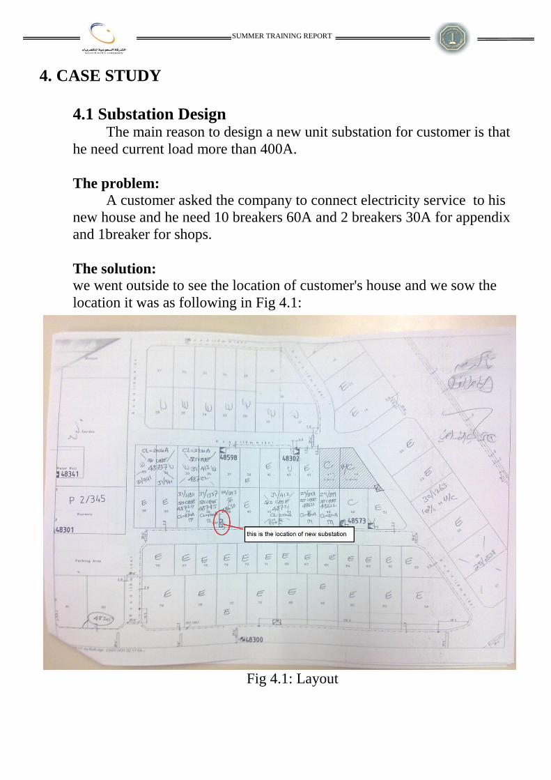
4. CASE STUDY
4.1 Substation Design The main reason to design a new unit substation for customer is that
he need current load more than 400A.
The problem:
A customer asked the company to connect electricity service to his
new house and he need 10 breakers 60A and 2 breakers 30A for appendix
and 1breaker for shops.
The solution:
we went outside to see the location of customer's house and we sow the
location it was as following in Fig 4.1:
Fig 4.1: Layout

SUMMER TRAINING REPORT
calculation of customer load:
AI 810]150)302()6010[( which is greater than 400A
V=220v
KVAVIs 30981022033
Demand load:
Residential
the floor:
7.185615.1
5.06010
DL
DvF
DFInDL
appendix:
69.21383.1
5.0302
DL
*Total Demand load:
DL=185.7+21.69+90=297.39 A
KVAs 2.1132972203
we needed cable size 4x300 which can carry 310A.
and we decided to put 500KVA transformer for future and empty area.
Fig 4.2: Single Line Diagram
Commercial
906.01501
DL
DFInDL
SUMMER TRAINING REPORT
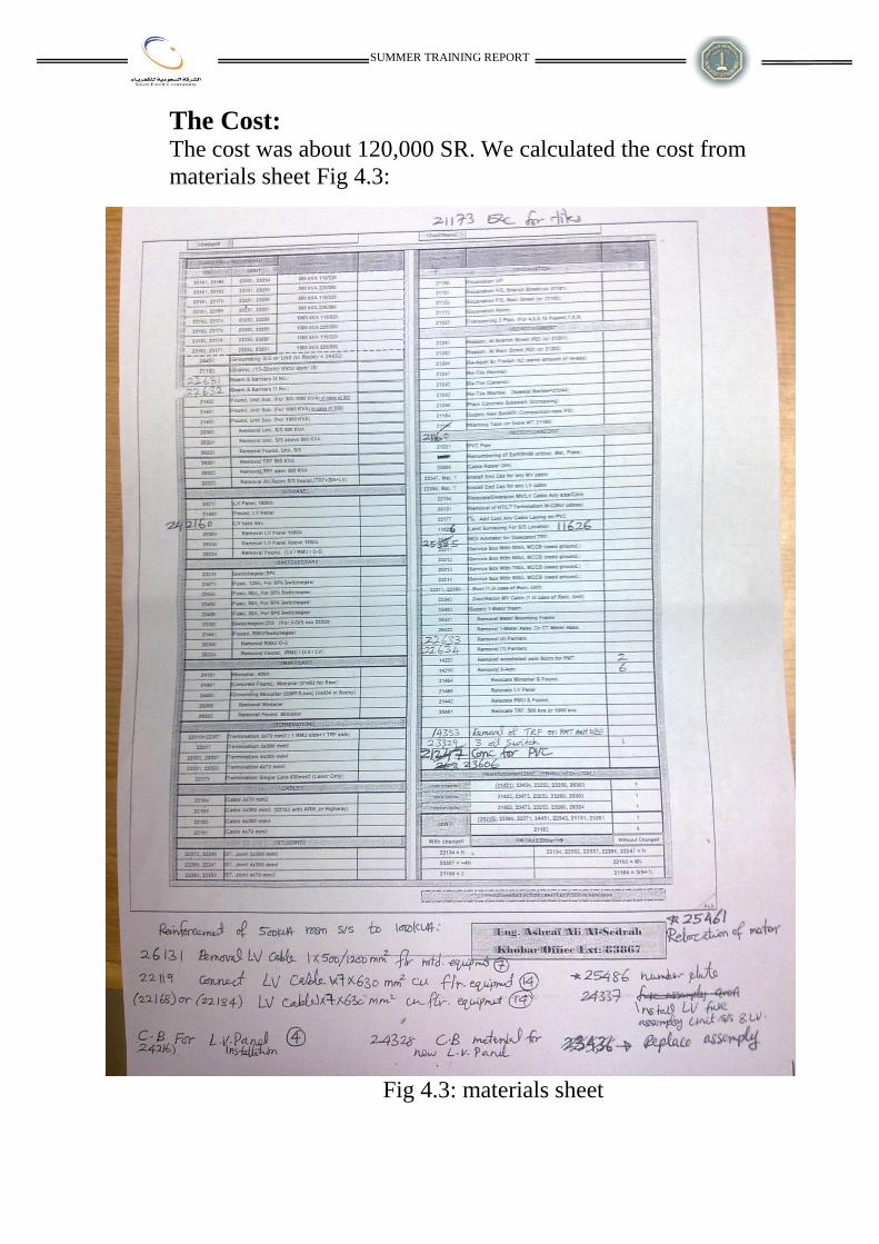
The Cost: The cost was about 120,000 SR. We calculated the cost from
materials sheet Fig 4.3:
Fig 4.3: materials sheet

SUMMER TRAINING REPORT
CONCLUSION
Actually, my summer training was absolute interesting, because I could
get great useful through that period. Such that, I could perform something that
studied before in some courses. So, I could make good connection between
work life and academic life. During that period, I took good knowledge about
power planet, transmission lines, substations, emergency and maintenance unit
and some devices and elements.
Finally, I thank the god first then everybody in company and university
who help me to learn and get any information and I hope that you found and
get the benefit by reading this report.