kitchen ventilation systems - licences and …bulletins.vancouver.ca/2007/2007-005.pdf ·...
TRANSCRIPT

H:\CBO\BULLETINS\2007 VBBL\2007\005.doc
City Hall 453 West 12th Avenue Vancouver BC V5Y 1V4 www.vancouver.ca Office of the Chief Building Official tel: 604.873.7515 fax: 604.873.7100
COMMUNITY SERVICES GROUPOffice of the Chief Building Official
BULLETIN 2007-005-BU/PL/EL/EV/AD April 10, 2007
KITCHEN VENTILATION SYSTEMS (Commercial-type Cooking Operations)
The attached Kitchen Ventilation Guidelines, check sheets and inspection tags/decals provide guidance for the design, installation and maintenance of kitchen ventilation systems in the City of Vancouver. These guidelines are jointly issued by the Chief Building Official1, Fire and Rescue Services, Vancouver Coastal Health Authority and Development Services to create one standard. They apply to both new and existing installations. Parties involved in designing, supplying, installing, operating, maintaining and inspecting kitchen systems can benefit from the attached information. The following highlights specific information for a number of these parties: Permit Submission Requirements: The K1 checklist (attached) summarizes the professionals and
documents required for a building permit. Refer also to Section IV titled “Submission for Building Permit” on page 8.
Owner: The owner is responsible to obtain all permits, or approvals, prior to commencing work and to
ensure all work carried out is in accordance with the Vancouver Building By-law2. For example, if changing one’s menu changes the cooking operation to a Class 1 Cooking Operation (see definition page 5), a permit is required. The owner, or an authorized agent of the owner, is responsible for carrying out the requirements of the Fire By-law3, including maintenance and keeping of records of inspections4. This includes ensuring daily cleaning of the hood filters. The Annual Fire Prevention Inspection checklist on page 14 indicates the minimum
required frequency of inspections. The diagram on page 3 of the Guidelines illustrates where maintenance tags for inspection
should be located. For existing systems, where a duct cleaner is unable to clean a portion of the duct due to
lack of access, access panels are required to be installed to enable inspection and cleaning as required by the 2000 Vancouver Fire By-law [VFBL 2.6.1.3.(1) & 2.6.1.9.(3)]. This includes existing ductwork downstream of an ecology unit. Refer to the section on page 15.
The operator of a food premises, namely the owner, manager, or lessor, is required to immediately notify a health official of any circumstance that exists in the food premises that may cause a health hazard [BC Health Act, Food Premises Regulations, Part 3, Division 1, Item 7] 5.
1 Italicized words are defined in the 2007 Vancouver Building By-law Sentence 1.4.1.2.(1) of Division A. 2 2007 Vancouver Building By-law, Sentences 1A.3.1.3.(1) and 1A.3.4.1.(1) of Division C. 3 2000 Vancouver Fire By-law, Sentence 1.1.1.1.(1). 4 2000 Vancouver Fire By-law, Sentence 1.1.1.6.(1). 5 http://www.qp.gov.bc.ca/statreg/reg/H/Health/210_99.htm#7

BULLETIN 2007·00S·BU/PLIELIEV/ADKITCHEN VENTILATION SYSTEMS
April 10, 2007Page 2 of 2
No person is permi tted to discharge or atlow or cause the di scharge of any " Ai r Contamtnant '" inthe course of conduct ing an industry , t rade or business of whatsoever kind or nature, except aspermitted by the Greater Vancouver Regional District Air Quality Management Bylaw?
Mechanical Engineer: Five Classes of Cooking Operations have been created to cla ri fy when NFPA 96 isrequired . Refer to page 4 in the attached Guidelines.
The K2 checkl ist summarizes the Cit y' s minimum design requirements. Thi s document is requi redto be completed for aU Building Permit submissions for Class 1 Cooking Operations.
Architect I Structural Engineer I Electrical Engineer: The K1 and K2 checklists summarize thearch itectural , st ructural and electrica l requi rements.
Kitchen Exhaust Cleaner ("Duct Cleaner"): As part of a kitchen exhaust clea ner's inspection andrepo rting requirements [VFBL Article 6.1. 1.5 & NFPA 96, 8-3.1.2], the cleaner is responsible tonote the state of an ecology unit' s filters and whether they appear to have been by-passed,Refer to the sect ion on Maintenance of Ecology Units, page 17.
Contractor: Inspection Checklists are included starting on page 10. These items shall be checked forcompliance before calling for a City inspector .
Ecology Unit and UV Maintenance Companies: Inspection tags/decals are attached. These are to belocated at the hood' s f ixed f i re suppression container (or attached to t he fron t of the hood) formaintenance inspection , as illustrated on page 3.
Product Manufacturers: For the acceptab ility of new kitchen equipment, refer to the Contacts sect ionon page 21.
Public Enquiries: Refer to t he Contacts sect ion on page 21.
M.Z. Meszaros, P.Eng.BUILDING CODE SPECIALIST
Attachments :• Kitchen Ventilation Guidelines• K1, Building Application Submission Requirements• K2, Kit chen Ventilation Details Checkli st• K3, Commitment Not To Create Grease-Laden Vapours• Ecology Unit Inspection and Maintenance Tag• UV inspect ion Inspect ion and Maintenance Tag
6 Defi ned t erm in the GVRO Air Quali ty Management Bylaw No. 937, 1999.7 GVRD Air Quali ty Management Bylaw No. 937, 1999 (http: / / www.gvrd.bc.ca/air / pdfs/aqb ylaw.pdf)
453 West 12th Avenue Vancouver, BC V5Y 1V4 www.vancouver.ca April 10, 2007
CHIEF BUILDING OFFICIAL D.H. Jackson, P.Eng. DEPUTY CHIEF FIRE PREVENTION L. Sziklai DIRECTOR, VANCOUVER COASTAL HEALTH AUTHORITY N. Losito CO-DIRECTOR, DEVELOPMENT SERVICES—POLICY AND REGULATION F.A.(Rick) Scobie
KITCHEN VENTILATION GUIDELINES (Commercial-type Cooking Operations)
This Guideline is jointly issued by the Chief Building Official1, Fire and Rescue Services, Vancouver Coastal Health Authority and Development Services. It is intended to provide answers and guidance for the minimum standard for new and existing kitchen ventilation systems in the City of Vancouver. Table of Contents I Definitions 2 II Typical Kitchen Terminology 3 a) Standard set-up 3 b) With an ecology unit 4 III Classes of Cooking Operation - NFPA 96 Scope 4 IV Submission for Building Permit 8 V Design Considerations for Development Permit 9 VI Inspections 10 VII Access Panels 15 VIII Ecology Units 16 a) General Requirements 16 b) Maintenance of Ecology Units 17 IX UV Technology 19 X Contacts 21
1 Italicized words are defined in the 2007 Vancouver Building By-law Sentence 1.4.1.2.(1) of Division A.
BULLETIN 2007-005-BU/PL/EL/EV/AD April 10, 2007 KITCHEN VENTILATION GUIDELINES Page 2 of 22
I. Definitions
“Domestic Hood” means a metal hood designed for use over domestic cooking equipment. Typically, a domestic hood is installed per VBBL-B2 9.10.22. and 9.32 and has filters for grease removal [VBBL-B 9.32.3.9.(6) and 9.32.3.12.(2)]. “Ecology Unit” means a device used for the cleaning of exhaust air and is listed in conformance with ULC-S647-05, “Standard for Exhaust Cleaning and Recirculation Assemblies for Commercial and Institutional Kitchen Exhaust Systems”. Other terms used for an ecology unit in the industry are ecologizer, Air Purification Unit (“APU”), Pollution Control Unit (“PCU”), “air pollution control device” (NFPA 963, 3.3.3) and proprietary names such as Halton’s (previously known as Vent Master) Ecoloair, Spring Air’s Enviro Unit, Carroll’s EnvironAir, and Quiet-Aire’s Ecology APU. An ecology unit typically has a large metal box in the exhaust path. Generally, the metal box includes 3 large filters plus an exhaust fan, with the fan and sensors controlled by a panel typically mounted in the kitchen area (refer to the diagram in Section II b). “NFPA 96” is the “Standard for Ventilation Control and Fire Protection of Commercial Cooking Operations”. Kitchen systems complying with this standard typically have welded steel ductwork, a heavy duty exhaust hood (Type I Hood), fire suppression underneath the hood and a make-up air system. The 2001 edition is the applicable version under the 2007 Vancouver Building By-law. “Type I Hood” means a hood designed in conformance with NFPA 96 [NFPA 96, A.3.3.31] and constructed per NPFA 96, Chapter 5. Typically, the hood is externally welded so that it is liquid-tight and is of 18 gauge steel or 20 gauge stainless steel [NFPA 96, 5.1.1 and 5.1.2]. “Type II Hood” means a hood designed for heat and steam removal and other non-grease applications. It is generally seamed. A condensate hood with an exhaust is a Type II hood.
2 “VBBL” means Vancouver Building By-law 2007 No.9419 including Amendments, and “-B” means “Division B” of the By-law. 3 All references to NFPA 96 are to the 2001 edition, unless noted otherwise.

BULLETIN 2007-005-BU/PL/EL/EV/AD April 10, 2007 KITCHEN VENTILATION GUIDELINES Page 3 of 22
:
II. Typical Kitchen Terminology a) Standard set-up Typical terminology used for a standard set-up kitchen ventilation system is shown in the figure below.
BULLETIN 2007-005-BU/PL/EL/EV/AD April 10, 2007 KITCHEN VENTILATION GUIDELINES Page 4 of 22
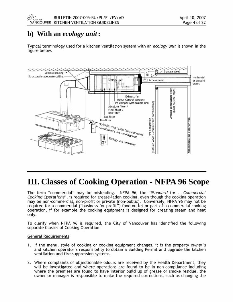
:b) With an ecology unit Typical terminology used for a kitchen ventilation system with an ecology unit is shown in the figure below.
III. Classes of Cooking Operation - NFPA 96 Scope The term “commercial” may be misleading. NFPA 96, the “Standard for … Commercial Cooking Operations”, is required for grease-laden cooking, even though the cooking operation may be non-commercial, non-profit or private (non-public). Conversely, NFPA 96 may not be required for a commercial (“business for profit”) food outlet or part of a commercial cooking operation, if for example the cooking equipment is designed for creating steam and heat only. To clarify when NFPA 96 is required, the City of Vancouver has identified the following separate Classes of Cooking Operation: General Requirements 1. If the menu, style of cooking or cooking equipment changes, it is the property owner’s
and kitchen operator’s responsibility to obtain a Building Permit and upgrade the kitchen ventilation and fire suppression systems.
2. Where complaints of objectionable odours are received by the Health Department, they
will be investigated and where operations are found to be in non-compliance including where the premises are found to have interior build up of grease or smoke residue, the owner or manager is responsible to make the required corrections, such as changing the
BULLETIN 2007-005-BU/PL/EL/EV/AD April 10, 2007 KITCHEN VENTILATION GUIDELINES Page 5 of 22
type of cooking (menu change) or changing the equipment to comply with the appropriate Class of Cooking Operation.
3. Where the City deems it necessary, a letter from both the mechanical engineer and the
owner may be required to confirm that the proposal complies with one of the Classes of Cooking Operation prior to issuance of the Building Permit. A sign may also be required to be visibly displayed in the kitchen to describe the Class of Cooking Operation.
4. As per the 2000 Vancouver Fire By-law Sentence A-2.4.3.2.(4), propane use indoors is only
permitted where
a. the appliance is listed for propane use indoors, b. the max. number of propane tanks directly connected to food service appliances is
two 2.7 lbs “single trip” (non-refillable) propane cylinders, and c. the maximum number of 2.7 lbs cylinders in storage is ten.
Class 1 Cooking Operation (grease-laden vapours)
A Class 1 Cooking Operation is defined as any cooking process which produces significant smoke or grease-laden vapours, and includes any equipment which has been designed by the manufacturer to be able to produce significant smoke or grease-laden vapours, except where specifically approved under another Class. The following requirements apply to Class 1 Cooking Operations:
• Full compliance with NFPA 96 (Type I hood)
• Minimum 50 GPM grease interceptor [March 13, 1997 City of Vancouver Notice “Grease Traps and Interceptors Policy”, VBBL-B 7.4.4.3, and Sewer and Watercourse By-law #8093, 3.1.(4)(d)].
Note: Mesh filters are not permitted in new installations [NFPA 96, 6.1.3]. It is recommended that mesh filters in existing systems be replaced due to increased fire risk.
Examples of Class 1 Cooking Operations include:
• cooking operations outside the scope of Classes 2 through 5
• the following commercial-type equipment or, domestic-type equipment used in a commercial-like food-processing establishment [VBBL-B 6.2.2.6 and A-9.10.1.3.(1)4]:
range (burners or hot top), stove, hot plate (gas burner, electric coil or flat top), induction cooker, electric frying pan, conveyor convection oven if used for cooking chicken wings or other bulk meat, oven used for cooking meat, char broiler, wok, fry grill, griddle, salamander, deep fat fryer, pan frying, barbecue, rotisserie, Donair vertical broiler, tilting skillet, braising pan, any equipment recommended to have fire suppression by the manufacturer, any equipment which produces or has been designed by the manufacturer to have the potential to produce comparable amounts of smoke or grease. [NFPA 96, A.10.1.2]
• cooking operations which receive complaints of producing objectionable odours or are found to cause interior build up of grease or smoke residue [Provincial Health Act].
4 NFPA 96, 1.1.2, domestic equipment used for a commercial operation is considered a Class 1 Cooking Operation.

BULLETIN 2007-005-BU/PL/EL/EV/AD April 10, 2007 KITCHEN VENTILATION GUIDELINES Page 6 of 22
Class 2 Cooking Operation (steam and heat removal)
A Class 2 Cooking Operation is defined as any cooking equipment or process which produces significant steam or heat but does not produce grease-laden vapours. Note: Exhaust is not permitted to discharge into a storage garage (parkade or loading bay) as
per VBBL-B Article 6.2.3.8.(5) & (6). The following requirements apply to Class 2 Cooking Operations:
• Type II hood and exhaust with general HVAC ducting
• If the ductwork is combined with ductwork serving a Class 1 Cooking Operation, then the ventilation for the Class 2 Cooking Operation is required to comply with NFPA 96 except that the air flow volume may be designed for heat and steam removal only. [NFPA 96, 7.1.3]
• If an appliance is designed with the potential for Class 1 Cooking, and will only be used for Class 2 Cooking, then the following are additional requirements:
1) completed Form K3, Commitment Not to Create Grease-laden Vapours5, and
2) a metal sign securely mounted to the front of the hood embossed with the following words sized and coloured so that they can be easily read and understood6: COOKING CAUSING GREASE-LADEN VAPOURS IS NOT ALLOWED. EXHAUST SYSTEM IS DESIGNED FOR STEAM AND HEAT REMOVAL ONLY.
Examples of Class 2 Cooking Operations include:
• any of the following if they are > 6 kW (20,478 BTU/h)7: closed pizza oven, conveyor pizza oven if used only for pizza or bread, baking oven, coffee maker, coffee roaster, hot dog display heater, pastry oven, popcorn maker, roll warmer, steam reconstitution device, steamer, toaster, warming oven
• open Bain Marie
• the following would be considered appliances designed with the potential of Class 1 Cooking but used only for Class 2 Cooking: an electric domestic range, hot plate or induction cooker in a commercial cooking establishment used only for non-grease applications such as boiling water (e.g., potatoes, pasta, rice), reheating pre-made soups, heating beverages (e.g., hot chocolate) or melting chocolate. (See additional requirements above.)
5 The intent of the K3 Form is for Cooking Operations where it is reasonable to expect that no cooking causing grease-laden vapours will occur now or in the future. In the form, the business operator acknowledges awareness that any grease in a non-NFPA 96 ventilation system may put the ventilation system in an unsafe condition. 6 The objective of the sign is to advise and remind staff in the kitchen not to create grease vapours, identify the cooking operation for inspectors, and identify the system’s limitations for future buyers of the operation. 7 1 kW = 3,413 Btu/h

BULLETIN 2007-005-BU/PL/EL/EV/AD April 10, 2007 KITCHEN VENTILATION GUIDELINES Page 7 of 22
Class 3 Cooking Operation (dwelling units)
A Class 3 Cooking Operation is defined as any cooking equipment or process where limited smoke and limited grease-laden vapours are produced such as in normal usage in a single-family home. This Class of Cooking Operation typically utilizes a domestic range. If a sign is required per the General Requirements at the beginning of this section, it should read: “This is a Class 3 Cooking Operation, with a grease capacity alike to a single-family residence. No commercial cooking is permitted, including preparation of meals for more than a normal household on a regularly repeated basis.” The following requirements apply to Class 3 Cooking Operations:
• A domestic hood with a grease filter is the required minimum.
• The exhaust and make-up air systems must comply with the requirements for a typical self-contained mechanical ventilation system serving only one dwelling unit [VBBL-B Part 9 and Part 6].
• Fire rate around that portion of the exhaust duct which is located within another fire compartment.
• Except within dwelling units, fire extinguisher(s) located in the kitchen area [VFBL8
6.2.3.2, NFPA 96 1.1.4.(2)]
Examples of Class 3 Cooking Operations include:
• single-family usage
• a single, four burner domestic range9 in a Fire Hall
• a single, four burner domestic range in an amenity room in a residential building, care home, congregate housing, employee break room or church where there is no cooking that produces grease-laden vapours, e.g., used for food warming or baking cakes (a microwave is recommended rather than a range where possible) [NFPA 96, A.1.1.4]
• a home-economics classroom in a high school where only domestic cooking is taught
• domestic range in a Licensed Childcare Facility. The menu is regulated by the Vancouver Coastal Health Authority.
• a single domestic range used in a showroom that sells non-food products, such as a showroom for selling domestic ranges, where the range is used once on the occasional day for a small number of people.
• Class 3 does not include commercial food operations.
Class 4 Cooking Operation (self-contained)
A Class 4 Cooking Operation is defined as cooking equipment listed by an accredited certification organization such as ULC, cUL or ETL to ventilate into the room. These devices typically have their own fire suppression and grease filtering systems. 8 “VFBL” means 2000 Vancouver Fire By-law 9 VBBL-B Sentence 9.10.1.3.(1) requires a commercial range to be considered a Class 1 Cooking Operation.

BULLETIN 2007-005-BU/PL/EL/EV/AD April 10, 2007 KITCHEN VENTILATION GUIDELINES Page 8 of 22
The following requirement applies to Class 4 Cooking Operations:
• Comply with the manufacturer’s installation, operational and listing requirements. Examples of Class 4 cooking equipment include:
• Giles Ventless Hood Fryer (previously called Chester Fried Ventless Hood Fryer)
• Perfect Fryer PFC model series, ventless commercial deep fat fryers
• Belshaw Donut Robot Fryer with Insider ventless cabinet
Class 5 Cooking Operation (no hood)
A Class 5 Cooking Operation is defined as cooking equipment where a hood is not provided. Products from the cooking operation may be removed by the room ventilation. Class 5 does not include cooking procedures which produce significant grease-laden vapours, significant steam or significant heat. Where complaints are received by the Health Department such as mould from too much moisture, over-heating in the work environment, objectionable odours, or build up of grease or smoke residue, the owner or manager is responsible to make the required corrections, such as a menu change or applying for a building permit to comply with the appropriate Class of Cooking Operation. Examples of Class 5 Cooking Operations include:
• the following if they are ≤ 6 kW: coffee maker, coffee roaster, hot dog display heater, pastry oven, closed pizza oven, baking oven, warming oven, popcorn maker, roll warmer, toaster
• Pennine grills (for making Pennines, i.e., not for processes which cause grease-laden vapours such as grilling or braising meat)
• microwave oven, crock pot
IV. Submission for Building Permit For a Class 1 Cooking Operation, a review of the kitchen ventilation system is required by the Processing Centre – Building Branch. The required submission documents for a Building Permit are summarized in “K1 – Restaurants or Kitchen Exhaust Systems – Building Application Submission Requirements” One of the required documents is “K2 – Kitchen Ventilation Details Checklist”. Where there are multiple professionals responsible for various components, each professional may complete a separate copy of the form, initialling only those areas for which they are responsible. It is the registered professional’s responsibility to understand and comply with all the regulations and to design a system which functions in accordance with good engineering practice. Under an existing hood, if the type of cooking appliance is changed or an existing appliance line-up is reorganized, this affects the type and location of fire suppression nozzles

BULLETIN 2007-005-BU/PL/EL/EV/AD April 10, 2007 KITCHEN VENTILATION GUIDELINES Page 9 of 22
[NFPA 96, 12.1.2.2], the amount and distribution of exhaust flow under the hood and the make-up air system. Another example is when an existing hood is moved, this changes the distances of the hood and ductwork from neighbouring objects which affects their required protection. For modifications to an existing Class 1 Cooking Operation ventilation system including modifications to the appliance line-up or relocating an existing hood, a new or revised Building Permit and a fully completed K2 checklist are required complete with Schedules B-1 and B-2 and sealed drawings. For all the other Classes of Cooking Operations, the Building Permit process does not include a review of the kitchen ventilation system by the Processing Centre – Building Branch. The following lists required documents to be submitted with the Building Permit application: Class 2, where the appliance has potential for Class 1: 1. Form K3, Commitment Not To Create Grease-laden Vapours Class 4: 1. ULC, cUL or ETL listing for the ventless hood, and 2. mechanical drawings indicating room ventilation as required by the listing
V. Design Considerations for Development Permit For a Development Permit or combined Development and Building Permit, ductwork should not negatively impact the liveability of other spaces. More specifically, ductwork or roof top equipment should not create a negative visual, noise or smell impact to pedestrians or nearby residential or office units.
Roof top equipment should be located away from the edge of the building, and/or screened, such that the equipment is not visible from the street level or exposed to nearby residential or office windows.
Ductwork should run inside the building to the uppermost roof or discharge horizontally through an ecology unit to a lane (or to a street where there is no lane and the discharge is approved by the Director of Planning). (Refer to Section VIII for acceptable discharge locations. Refer to page 20, point 4, for additional criteria for UV discharge locations.)
For existing situations where it is difficult to run the duct entirely inside the building, the Director of Planning may permit the duct to run up the outside of the building to the roof above residential units, office units and openable windows. Mitigating measures could include the following, or other measures to the satisfaction of the Director of Planning:
the ductwork is concealed by an enclosure which visually integrates it with the existing building’s façade,
the assembly is located away from windows so that others’ views are not negatively impacted, and
the assembly is proposed at the rear, or lane side, of the building. Applications with Outright Approval Uses are not required to comply with these Design Considerations when there are no relaxations or non-conformities to the Zoning and Development By-law or Parking By-law.
Applicants should confer with the Enquiry Centre of Development Services (2nd floor, East Wing of City Hall, 2675 Yukon St., Vancouver, (604) 873-7611 or -7613).
Refer to Section VII for access panels for maintenance. Refer to the K1 checklist for other required submission documents (e.g., roof and elevation photographs and letter of approval from the Strata Council).
BULLETIN 2007-005-BU/PL/EL/EV/AD April 10, 2007 KITCHEN VENTILATION GUIDELINES Page 10 of 22
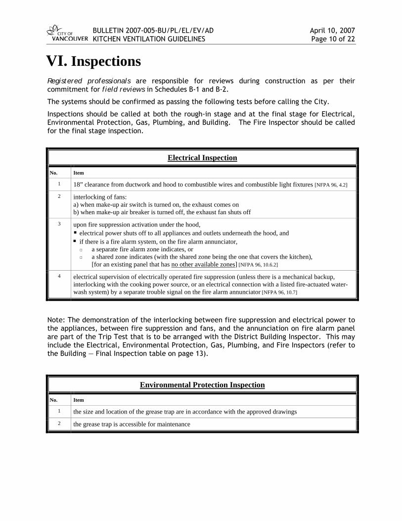
VI. Inspections Registered professionals are responsible for reviews during construction as per their commitment for field reviews in Schedules B-1 and B-2.
The systems should be confirmed as passing the following tests before calling the City.
Inspections should be called at both the rough-in stage and at the final stage for Electrical, Environmental Protection, Gas, Plumbing, and Building. The Fire Inspector should be called for the final stage inspection.
Electrical Inspection
No. Item
1 18” clearance from ductwork and hood to combustible wires and combustible light fixtures [NFPA 96, 4.2]
2 interlocking of fans: a) when make-up air switch is turned on, the exhaust comes on b) when make-up air breaker is turned off, the exhaust fan shuts off
3 upon fire suppression activation under the hood, electrical power shuts off to all appliances and outlets underneath the hood, and if there is a fire alarm system, on the fire alarm annunciator,
a separate fire alarm zone indicates, or a shared zone indicates (with the shared zone being the one that covers the kitchen),
[for an existing panel that has no other available zones] [NFPA 96, 10.6.2]
4 electrical supervision of electrically operated fire suppression (unless there is a mechanical backup, interlocking with the cooking power source, or an electrical connection with a listed fire-actuated water-wash system) by a separate trouble signal on the fire alarm annunciator [NFPA 96, 10.7]
Note: The demonstration of the interlocking between fire suppression and electrical power to the appliances, between fire suppression and fans, and the annunciation on fire alarm panel are part of the Trip Test that is to be arranged with the District Building Inspector. This may include the Electrical, Environmental Protection, Gas, Plumbing, and Fire Inspectors (refer to the Building — Final Inspection table on page 13).
Environmental Protection Inspection
No. Item
1 the size and location of the grease trap are in accordance with the approved drawings
2 the grease trap is accessible for maintenance
BULLETIN 2007-005-BU/PL/EL/EV/AD April 10, 2007 KITCHEN VENTILATION GUIDELINES Page 11 of 22
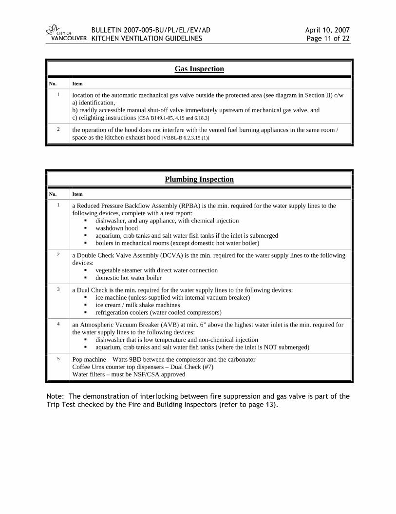
Gas Inspection
No. Item
1 location of the automatic mechanical gas valve outside the protected area (see diagram in Section II) c/w a) identification, b) readily accessible manual shut-off valve immediately upstream of mechanical gas valve, and c) relighting instructions [CSA B149.1-05, 4.19 and 6.18.3]
2 the operation of the hood does not interfere with the vented fuel burning appliances in the same room / space as the kitchen exhaust hood [VBBL-B 6.2.3.15.(1)]
Plumbing Inspection
No. Item
1 a Reduced Pressure Backflow Assembly (RPBA) is the min. required for the water supply lines to the following devices, complete with a test report:
dishwasher, and any appliance, with chemical injection washdown hood aquarium, crab tanks and salt water fish tanks if the inlet is submerged boilers in mechanical rooms (except domestic hot water boiler)
2 a Double Check Valve Assembly (DCVA) is the min. required for the water supply lines to the following devices:
vegetable steamer with direct water connection domestic hot water boiler
3 a Dual Check is the min. required for the water supply lines to the following devices: ice machine (unless supplied with internal vacuum breaker) ice cream / milk shake machines refrigeration coolers (water cooled compressors)
4 an Atmospheric Vacuum Breaker (AVB) at min. 6” above the highest water inlet is the min. required for the water supply lines to the following devices:
dishwasher that is low temperature and non-chemical injection aquarium, crab tanks and salt water fish tanks (where the inlet is NOT submerged)
5 Pop machine – Watts 9BD between the compressor and the carbonator Coffee Urns counter top dispensers – Dual Check (#7) Water filters – must be NSF/CSA approved
Note: The demonstration of interlocking between fire suppression and gas valve is part of the Trip Test checked by the Fire and Building Inspectors (refer to page 13).

BULLETIN 2007-005-BU/PL/EL/EV/AD April 10, 2007 KITCHEN VENTILATION GUIDELINES Page 12 of 22
Building Inspection (c/w Fire Inspection at final stage)
Witnessing of the Trip Test at the final inspection will be a joint inspection by the District Building Inspector and the Fire Inspector. Note: for final clearance, the Building Inspector will need clearance from the Electrical, Environmental Protection, Gas, Plumbing, and Fire Inspectors.
Building Rough-in Inspection
No. Item
1. Clearances from the hood and from non-shafted ductwork [NFPA 96, Table A.3.3.34 and 4.2]: Note: noncombustible = ceramic tile or plaster on brick, clay or concrete; or, brick, clay or concrete limited combustible = GWB on metal studs or joists combustible = GWB on wood studs or joists
a combustibles: 18” / 9” w 28-gauge+spacers / 3” w 22-gauge on insul.+spacers limited comb’s: 3” / 0” w layer of noncomb. material noncomb.’s: 0”
2. Clearance from a shafted ductwork [NFPA 96, 7.7.2.2]:
a combustibles: 18” limited combustibles: 6” noncombustibles: 6”
BULLETIN 2007-005-BU/PL/EL/EV/AD April 10, 2007 KITCHEN VENTILATION GUIDELINES Page 13 of 22
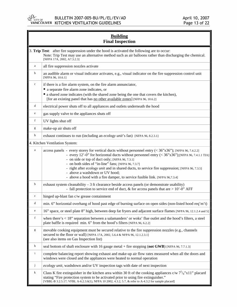
Building Final Inspection
3. Trip Test: after fire suppression under the hood is activated the following are to occur: Note: Trip Test may use an alternative method such as air balloons rather than discharging the chemical. [NFPA 17A, 2002, A7.3.2.3]
a all fire suppression nozzles activate
b an audible alarm or visual indicator activates, e.g., visual indicator on the fire suppression control unit [NFPA 96, 10.6.1]
c if there is a fire alarm system, on the fire alarm annunciator, a separate fire alarm zone indicates, or a shared zone indicates (with the shared zone being the one that covers the kitchen), [for an existing panel that has no other available zones] [NFPA 96, 10.6.2]
d electrical power shuts off to all appliances and outlets underneath the hood
e gas supply valve to the appliances shuts off
f UV lights shut off
g make-up air shuts off
h exhaust continues to run (including an ecology unit’s fan) [NFPA 96, 8.2.3.1]
4. Kitchen Ventilation System:
a access panels - every storey for vertical ducts without personnel entry (< 36”x36”); [NFPA 96, 7.4.2.2] - every 12’-0” for horizontal ducts without personnel entry (< 36”x36”);[NFPA 96, 7.4.1.1 TIA] - on side or top of duct only; [NFPA 96, 7.3.1] - on both sides of “in-line” fans; [NFPA 96, 7.3.7] - right after ecology unit and in shared ducts, to service fire suppression; [NFPA 96, 7.3.5] - above a washdown or UV hood; - above a hood with a fire damper, to service fusible link. [NFPA 96,7.3.4]
b exhaust system cleanability – 3 ft clearance beside access panels (or demonstrate usability) - fall protection to service end of duct, & for access panels that are > 10’-0” AFF
c hinged up-blast fan c/w grease containment
d min. 6” horizontal overhang of hood past edge of burning surface on open sides (non-listed hood req’m’t)
e 16” space, or steel plate 8” high, between deep fat fryers and adjacent surface flames [NFPA 96, 12.1.2.4 and 5]
f when there’s < 18” separation between a salamanders’ or woks’ flue outlet and the hood’s filters, a steel plate baffle is required min. 6” from the hood’s filters [NFPA 96, 6.2.2]
g movable cooking equipment must be secured relative to the fire suppression nozzles (e.g., channels secured to the floor or wall) [NFPA 17A, 2002, 5.6.4 & NFPA 96, 12.1.2.3.1] (see also items on Gas Inspection list)
h seal bottom of shaft enclosure with 16 gauge metal + fire stopping (not GWB) [NFPA 96, 7.7.1.3]
i complete balancing report showing exhaust and make-up air flow rates measured when all the doors and windows were closed and the appliances were heated to normal operation
j ecology unit, washdown and/or UV inspection tags with date of next inspection
k Class K fire extinguisher in the kitchen area within 30 ft of the cooking appliances c/w 75/8”x11” placard stating “Fire protection system to be activated prior to using fire extinguisher.” [VBBL-B 3.2.5.17; VFBL A-6.2.3.6(1), NFPA 10 2002, 4.3.2, 5.7, & refer to A-4.3.2 for sample placard]
BULLETIN 2007-005-BU/PL/EL/EV/AD April 10, 2007 KITCHEN VENTILATION GUIDELINES Page 14 of 22
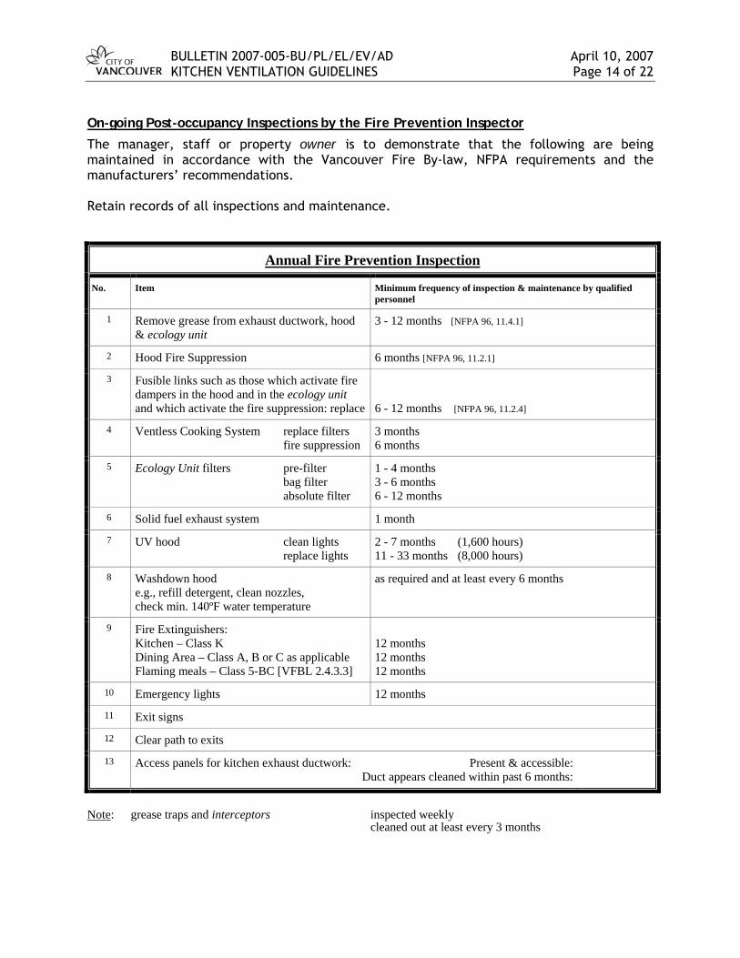
On-going Post-occupancy Inspections by the Fire Prevention Inspector
The manager, staff or property owner is to demonstrate that the following are being maintained in accordance with the Vancouver Fire By-law, NFPA requirements and the manufacturers’ recommendations. Retain records of all inspections and maintenance.
Annual Fire Prevention Inspection
No. Item Minimum frequency of inspection & maintenance by qualified personnel
1 Remove grease from exhaust ductwork, hood & ecology unit
3 - 12 months [NFPA 96, 11.4.1]
2 Hood Fire Suppression 6 months [NFPA 96, 11.2.1]
3 Fusible links such as those which activate fire dampers in the hood and in the ecology unit and which activate the fire suppression: replace
6 - 12 months [NFPA 96, 11.2.4]
4 Ventless Cooking System replace filters fire suppression
3 months 6 months
5 Ecology Unit filters pre-filter bag filter absolute filter
1 - 4 months 3 - 6 months 6 - 12 months
6 Solid fuel exhaust system 1 month
7 UV hood clean lights replace lights
2 - 7 months (1,600 hours) 11 - 33 months (8,000 hours)
8 Washdown hood e.g., refill detergent, clean nozzles, check min. 140ºF water temperature
as required and at least every 6 months
9 Fire Extinguishers: Kitchen – Class K Dining Area – Class A, B or C as applicable Flaming meals – Class 5-BC [VFBL 2.4.3.3]
12 months 12 months 12 months
10 Emergency lights 12 months
11 Exit signs
12 Clear path to exits
13 Access panels for kitchen exhaust ductwork: Present & accessible: Duct appears cleaned within past 6 months:
Note: grease traps and interceptors inspected weekly
cleaned out at least every 3 months

BULLETIN 2007-005-BU/PL/EL/EV/AD April 10, 2007 KITCHEN VENTILATION GUIDELINES Page 15 of 22
VII. Access Panels Ductwork that has not been properly cleaned on a regular basis or that is unable to be maintained due to lack of access panels is not in compliance with the By-laws. Access Panels Required
Access panels are required on all new and existing ductwork as per NFPA 96, including ductwork downstream of an ecology unit. Note: for existing vertical ducts only, an access panel at the top and at the side of the bottom may suffice rather than one at every storey as required by NFPA 96, Item 7.4.2.2, when an ASTTBC-CO member certifies that both the existing duct is clean and the duct is cleanable in the future by spin jetting (i.e., min. 3000 psi pressure wash). If an ASTTBC-CO member is unable to clean a duct due to lack of access, the member is to notify the owner, or an authorized agent of the owner, in writing and copy it to Vancouver Fire & Rescue Services.
Clearance Beside Access Panels
A minimum 3 foot clearance is required beside access panels / access hatches for a kitchen exhaust cleaner to work. Where access panels are within a fire rated enclosure, fire rated access hatches shall be provided for each access panel [VBBL 3.1.8.4.(2), NFPA 96, 7.4.4 & 7.7]. A sign shall be placed on all access panels/hatches stating the following: “ACCESS PANEL – DO NOT OBSTRUCT”. [NFPA 96, 7.1.6] It should be noted that WorkSafeBC regulations and NFPA 96 A.7.8.2.2 require a flat work area, such as a platform or area to set-up a platform, for the kitchen exhaust cleaner to be able to safely remove the access panels and clean the duct. Designs shall include a safe area available for the set-up of work platforms or mechanically elevated platforms. Alternatively, fall protection (such as a platform and guard rails) is required and/or attachments to enable the use of fall protection equipment where fall protection is required (e.g., required when there’s a potential fall > 10’-0”, or a potential fall ≤ 10’-0” which could cause injury, such as falling onto something sharp).
Access for Kitchen Exhaust Maintenance
Access panels for kitchen exhaust maintenance are to be readily accessible from within the cooking operator’s suite or via common property. Where there is a landlord, permission is to be obtained from the landlord to have ready access to all the panels for maintenance, or the landlord may provide the maintenance.

BULLETIN 2007-005-BU/PL/EL/EV/AD April 10, 2007 KITCHEN VENTILATION GUIDELINES Page 16 of 22
VIII. Ecology Units a) General Requirements The term ecology unit is defined in Section I and a typical equipment layout is shown in Section II.
Discharge
Sentence 6.2.2.6.(4) of Division B, VBBL 2007 states:
“A wall termination shall be located such that a) a concentrated stream of air will not discharge directly onto pedestrians, b) discharged exhaust will not accumulate in an area with outdoor seating, and c) the sound pressure level generated must be attenuated to be in compliance with
the Noise Control By-law.”
Note: The max. continuous noise in an Activity Zone, such as a street or lane, is 70 dBA during the daytime and 65 dBA during the night. Lower levels are required at points of reception within dwelling units.
Sentence A-6.2.2.6.(4) of Division B, VBBL 2007 states:
“The termination is also to be designed to the satisfaction of the Director of Planning.
• Where there is a canopy, the discharge should be located above the canopy. • The exhaust and make-up air locations should be determined respectful of existing
discharge, make-up air, operable window, and door locations of neighbouring properties.
• In some cases, the Director of Planning may not approve exhaust or make-up air wall terminations on street frontages.
• Wall terminations should be located where they have the least impact on nearby properties, suites, amenity areas, the public realm, windows, and building design.
• Generally, roof terminations are preferred and wall terminations should be located towards the lane.”
Where an ecology unit is provided, a wall termination is permitted right up to the lane property line or street property line [VBBL-B 6.2.2.6.(3)].
As a result of the requirements in VBBL 6.2.2.6.(4) noted above and the requirements in Section V, the preferred location for horizontal discharge is to a lane.
No Downgraded Ductwork
Downgrading of the ductwork after an ecology unit is not allowed per NFPA 96.
NFPA 96, 9.3:
“...air pollution control devices [i.e., ecology units], or other devices shall be permitted to be installed in ducts... Downgrading other parts of the exhaust

BULLETIN 2007-005-BU/PL/EL/EV/AD April 10, 2007 KITCHEN VENTILATION GUIDELINES Page 17 of 22
system due to the installation of these approved devices, whether listed or not, shall not be allowed.”
Access Panels after Ecology Unit
Any build up of grease in ductwork downstream of an ecology unit is required to be cleaned by a certified kitchen exhaust cleaner. Access panels necessary for this cleaning are required to be installed on all systems. Access panels necessary for servicing the fire suppression nozzles downstream of an ecology unit are required to be installed on all systems [NFPA 96, 9.3.3].
Fan Continues Running
When the fire suppression underneath a hood activates, if the exhaust fan was running, the exhaust fan is required to continue running [NFPA 96 8.2.3, NFPA 17A, 2002, 4.4.3.5]. An ecology unit fan is similarly required to continue running. This is so that the fire suppression discharge in the ductwork is drawn up the ductwork to suppress the fire. The motor overload protection device in an ecology unit may automatically stop the fan if the absolute filter becomes plugged.
No Enzyme Odour Control
Odour control by means of enzymes is not permitted.
b) Maintenance of Ecology Units This section has been established in cooperation with the ecology unit manufacturers, Vancouver Fire & Rescue Services, and a committee set-up by Applied Science Technologists and Technicians of BC (ASTTBC). Regular inspection, cleaning, filter changes (i.e., “grease removal devices”) and maintenance are required. A maintenance and inspection program was established in 1996 by Vancouver Fire & Rescue Services. This program now includes inspection of the ecology unit filters by the ASTTBC certified kitchen exhaust cleaner. Some of the By-law requirements are noted below: Inspection
“Hoods, ducts and filters subject to accumulations of combustible deposits shall be inspected at intervals not greater than 7 days, and shall be cleaned if the accumulation of such deposits creates a fire hazard.” [VFBL 2.6.1.3.(1)]
“Only service agencies are permitted to test or inspect a fire protection system, fire pump, emergency power or commercial kitchen exhaust system.” [VFBL 6.1.1.5.(1), NFPA 96 11.3]
“Service agent means a Registered Fire Protection Technician (RFPT) certified by the Applied Science Technologists and Technicians of British Columbia (ASTTBC) specifically for the testing and inspection of fire safety installations and equipment.”
A certified ASTTBC member with designation CO (Commercial Kitchen Cleaning), “ASTTBC-CO”, is to inspect the ecology unit filters for all, but not limited to, the following:
1. are the filters in place and clean
2. are the filters punctured, cut out or otherwise made ineffective
3. is there grease downstream of the ecology unit

BULLETIN 2007-005-BU/PL/EL/EV/AD April 10, 2007 KITCHEN VENTILATION GUIDELINES Page 18 of 22
4. are the filters listed
A certified ASTTBC member with designation SP (Special Suppression Systems), “ASTTBC-SP”, is to inspect and maintain the exhaust system fire suppression. This includes any additional nozzles in and after the ecology unit.
Filter Changes
Filters in an ecology unit are required to be changed in order to maintain minimum airflows and proper air-cleaning operation of the ecology unit. Filters are to be changed at frequencies as required by the ecology unit manufacturer and the City By-laws. Filter changes may be done by the owner, or the owner’s staff, in accordance with the manufacturer’s recommendations, or by a maintenance company certified by the manufacturer. Cleaning
“Hoods, grease removal devices, fans, ducts, and other appurtenances shall be cleaned at frequent intervals to prevent surfaces from becoming heavily contaminated with grease or other residues.” (Appendix note: “…In general, exhaust systems should be cleaned at intervals not greater than 12 months, but in the case of deep fat cooking, char broiling or similar cooking operations, the systems should be cleaned at intervals not greater than 3 months.”) [VFBL 2.6.1.9.(3), NFPA 96 11.4.2]
The ducts (upstream and downstream of an ecology unit), hoods and ecology unit boxes are required to be cleaned by an ASTTBC-CO member. Maintenance
“Maintenance and repairs shall be performed on all components at intervals necessary to maintain these conditions” [i.e., conditions of minimum airflows and good working condition of all components]. [NFPA 96, 4.1.5]
Tag
“A commercial kitchen exhaust system… shall have a tag securely attached to show the maintenance date, the name and signature of the service agent, and, if applicable, additional work required.” [VFBL 6.1.1.5.(1) and (4), NFPA 96 11.4.12 and 13]
The inspection and maintenance tags are required to be attached to the fire suppression discharge container (or to the hood) (see diagram in Section II) and a report is to be left on site. If there is a deficiency, the member is to tick or punch out the columns “work required” and “see report”. “Ecology unit” categories are included on the kitchen exhaust cleaner’s tag. Refer to ASTTBC for the required tag and report forms for kitchen exhaust cleaning inspection and maintenance. The owner is responsible to have a service company that is qualified by the ecology unit manufacturer to correct the ecology unit problem(s). Attached are tags for ecology unit and UV system inspection and maintenance. The service company is to complete the appropriate tag when the system has been inspected or serviced. The service company’s contact information is to be added to the tag.

BULLETIN 2007-005-BU/PL/EL/EV/AD April 10, 2007 KITCHEN VENTILATION GUIDELINES Page 19 of 22
IX. UV Technology There have been a number of enquiries about the “ultra-violet enhanced oxidation technology” (UV). The following provides some of this technology’s strengths and weaknesses to outline where its use is currently acceptable. Background UV uses processes called photolysis and ozonolysis to break down the grease. In photolysis, the UV-C10 disassociates the bonds within the grease atoms. In ozonolysis, oxygen atoms (O2) are disassociated and these recombine into ozone (O3) 11. The ozone then reacts with the grease and other organic compounds. The result from these processes is carbon dioxide (CO2), water (H2O), ozone, products such as peroxyacyl nitrates, and a small amount of white powder (Sodium, Calcium and organic compounds). Description The following lists the by-products from commercial cooking operations:
air borne grease particles (vaporised cooking oil and entrained fat) unburnt fuel gases (flammable vapours) and gaseous products of combustion non-grease organic material (food) smoke heat (thermal plume) water vapour
UV has been designed to reduce airborne grease particles and some non-grease organic material. The amount of grease converted to noncombustible gases depends on a few factors:
amount of grease in the air stream size of grease particles reaching the UV-C, amount of UV-C, and duration of time the exhaust is exposed to the UV-C and ozone
More grease remains in the air stream in the following situations:
heavy grease operations such as wok and char broiler cooking poor maintenance of the hood’s filtration ahead of the UV
10 The type of UV light used is class C (UV-C). According to various sources and provided as generic information for context only, UV light is electromagnetic radiation and in terms of human health and the environment is classified into three wavelength ranges:
i) UV-A, from 315 nm to 380 nm (i.e., “black light”) ii) UV-B, from 280 nm to 315 nm, and iii) UV-C, from 100 nanometers (nm) to 280 nm (i.e., short wave)
UV-C ≤ 240 nm disassociates oxygen molecules. These recombine to produce ozone. Between 200 and 310 nm (i.e., UV-C & UV-B), ozone disassociates and generally recombines to produce other ozone or oxygen. Long enough exposure to UV-C (5 to 2500 times longer than the exposure received by kitchen exhaust) at around 254 nm is effective at rendering germs, mold and odours harmless, i.e., no longer toxic, allergenic, or odour causing and no longer able to reproduce. This is done by defecting their DNA (i.e., effectiveness at absorption by DNA has two peaks at 185 nm and 265 nm). Laser eye surgery, i.e., breaking molecular bonds in human tissue, uses 193 nm. Uncontrolled exposure to UV-C is hazardous to humans. To further understand the differences in types of UV, ordinary air (21% oxygen) absorbs UV-C < 200 nm, i.e., the ozone-oxygen layer around the earth is a result of absorbing the UV-C and UV-B from the sun. Some UV-B is beneficial in that it produces Vitamin D in skin; however, over-exposure to UV-B is unhealthy (e.g., sun tan lotion ratings refer to protection from UV-B). Around 99% of the sun’s UV radiation that reaches the Earth's surface is UV-A. 11 ozone (O3), anionic oxygen (O-), hydroxyl radical (OH-), etc.

BULLETIN 2007-005-BU/PL/EL/EV/AD April 10, 2007 KITCHEN VENTILATION GUIDELINES Page 20 of 22
higher exhaust flow rates (e.g., island canopies), and shorter duct lengths
The location of the exhaust termination should be into a well ventilated area for dispersion of by-products. Strength Due to UV-C’s photolysis, less grease enters the ductwork. Due to ozonolysis in which excess ozone is carried down the ductwork during times of the day when cooking volumes are lower (i.e., less grease is entering the hood), the grease that may have settled inside the ductwork tends to get converted into gases. Thus, with the UV technology, the exhaust ductwork generally remains free of grease which reduces the fire hazard, duct maintenance and ecology unit filter maintenance. Weaknesses 1. Similar to other air cleaning systems, regular, almost daily, cleaning of the pre-UV
filtering stages (“pre-filters”) is required. If this is not done, large particles of grease are passed onto the UV lights. This blocks the UV from converting the grease in the air stream which results in more grease in the air stream downstream of the UV.
2. Operator maintenance is not self-regulated by the system. In the systems currently reviewed, there is no sensor to detect increased grease downstream of the UV lights to shut down the exhaust fan.
3. Fail-safe protection from exposure to the UV-C is required. UV-C is hazardous to human tissue12.
4. At non-cooking times, most of the ozone generated exits into the atmosphere13. Similarly, products from UV photolysis exit into the atmosphere14. The location of the exhaust termination should be into a well ventilated area for dispersion of these products. Further information can be obtained from the Greater Vancouver Regional District Air Quality Management Bylaw15.
5. NFPA 17A, 2002, 5.6.3 and A.5.6.3 state that permanently installed lights in an exhaust
system are considered an ignition source and shall be protected and have a separate detection system in accordance with the manufacturer’s recommendations. [NFPA 96, 9.3.4]
Inspection Tag To assist in consistency of the cleaning of the UV lights by the manufacturer's certified maintenance company, the maintenance company is required to leave a completed inspection tag in the kitchen area (refer to the diagrams in Section II). A sample UV inspection tag is attached. The maintenance company's contact information is to be added at the top of the tag.
12 Examples of eye damage are photokeratitis (inflammation of the cornea) known as "welder's flash", conjunctivitis known as "snow blindness", inflammation of the conjunctiva and retinal lesions. 13 Ozone is an irritant to the respiratory system. Ozone can have harmful effects on lung function. 14 Products from UV photolysis contribute to smog components such as peroxyacyl nitrates, which are eye irritants. 15 GVRD Air Quality Management Bylaw No. 937, 1999 (http://www.gvrd.bc.ca/air/pdfs/aqbylaw.pdf)
BULLETIN 2007-005-BU/PL/EL/EV/AD April 10, 2007 KITCHEN VENTILATION GUIDELINES Page 21 of 22
Conclusion Per NFPA 96, 9.3.1, "air pollution control devices" are permitted to be installed where they are specifically approved for such use. Currently, acceptable UV hoods are listed to ULC-S646 (and UL 710), the “Standard for Exhaust Hoods and Related Controls for Commercial and Institutional Kitchens”. As yet however, they have not been listed to ULC-S647-05 or listed as “air pollution control devices” so are not equivalent to ecology units.
X. Contacts For enquiries regarding: Contact:
Submission Checklists for Building Permits
K1, K2 and K3 are available at
www.vancouver.ca/commsvcs/developmentservices/subreq
or, contact (604) 873-7611 or (604) 873-7613
Cleaning of kitchen exhaust ducts, servicing of fire extinguishers, or servicing of other fire and life safety systems
Lieutenant, Customer Service, Vancouver Fire & Rescue Services at (604) 873-7595
Smells, noise, cleanliness of kitchen operation or other health issues
Vancouver Coastal Health at (604) 873-7566 or (604) 675-3800
Acceptance of new kitchen equipment
Chief Building Official’s Office, Manager of Professional Programs, ph: (604) 873-7053, fx: (604) 873-7100
ASTTBC certified members ASTTBC at (604) 585-2788 or
www.fireprotection.asttbc.org/registered.php
Kitchen Exhaust Cleaning Reports www.fireprotection.asttbc.org/forms.html
~"o, BULLETIN 2007·005·BU/ PLIELIEV/AOVANCOUVER KITCHEN VENTILATION GUIDELlNE5
April 10, 2007Page 22 of 22
M. Meszaros, P.Eng.BU ILDING CODE SPECIALIST
D.H. Jacks , .Eng.CHIEF BUILDI G OFFICIAL
~~~. osit it
DIREC , VANCOUVER COASTAL HEALTHAUTHORITY
~L'3-LF.. (R1Ck) ScobieCO·DIRECTOR, DEVELOPMENTSERVICES-POLICY AND REGULATION
Attachments:
• K1, Restaurants or Kitchen Exhaust Systems - Building Permit Submission Requirements• K2, Kitc hen Ventilation Details Checklist• K3, Commitment Not To Create Grease- laden Vapours• Ecology Unit Inspection and Maintenance Tag• UV Inspection and Maintenance Tag
April 10, 2007 Page 1 of 3
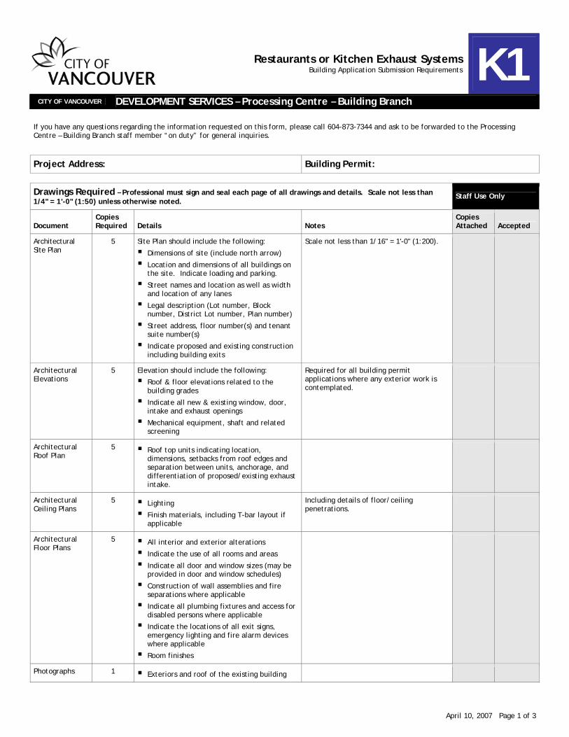
Restaurants or Kitchen Exhaust Systems Building Application Submission Requirements K1
CITY OF VANCOUVER DEVELOPMENT SERVICES – Processing Centre – Building Branch
If you have any questions regarding the information requested on this form, please call 604-873-7344 and ask to be forwarded to the Processing Centre – Building Branch staff member “on duty” for general inquiries.
Project Address: Building Permit:
Drawings Required – Professional must sign and seal each page of all drawings and details. Scale not less than 1/4" = 1'-0" (1:50) unless otherwise noted.
Staff Use Only
Document Copies Required Details Notes
Copies Attached Accepted
Architectural Site Plan
5 Site Plan should include the following:
Dimensions of site (include north arrow)
Location and dimensions of all buildings on the site. Indicate loading and parking.
Street names and location as well as width and location of any lanes
Legal description (Lot number, Block number, District Lot number, Plan number)
Street address, floor number(s) and tenant suite number(s)
Indicate proposed and existing construction including building exits
Scale not less than 1/16" = 1'-0" (1:200).
Architectural Elevations
5 Elevation should include the following:
Roof & floor elevations related to the building grades
Indicate all new & existing window, door, intake and exhaust openings
Mechanical equipment, shaft and related screening
Required for all building permit applications where any exterior work is contemplated.
Architectural Roof Plan
5 Roof top units indicating location, dimensions, setbacks from roof edges and separation between units, anchorage, and differentiation of proposed/existing exhaust intake.
Architectural Ceiling Plans
5 Lighting
Finish materials, including T-bar layout if applicable
Including details of floor/ceiling penetrations.
Architectural Floor Plans
5 All interior and exterior alterations
Indicate the use of all rooms and areas
Indicate all door and window sizes (may be provided in door and window schedules)
Construction of wall assemblies and fire separations where applicable
Indicate all plumbing fixtures and access for disabled persons where applicable
Indicate the locations of all exit signs, emergency lighting and fire alarm devices where applicable
Room finishes
Photographs 1 Exteriors and roof of the existing building

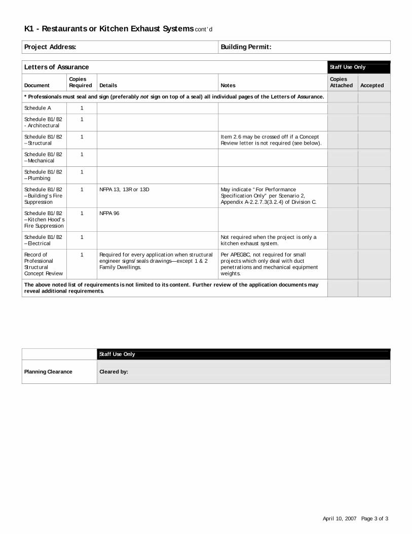
K1 - Restaurants or Kitchen Exhaust Systems cont’d
April 10, 2007 Page 2 of 3
Project Address: Building Permit:
Drawings Required – Professional must sign and seal each page of all drawings and details. Scale not less than 1/4" = 1'-0" (1:50) unless otherwise noted.
Staff Use Only
Document Copies Required Details Notes
Copies Attached Accepted
Construction Details/Cross Sections
5 Construction Details/Cross Sections should include the following:
Stair dimensions (width, rise, run, number of risers), height of guards, handrails and extensions
Wall, floor, roof and/or ceiling assemblies (written descriptions or cross sections)
Fire-resistance rating details of any required fire separations including test references (copy of listed assemblies where applicable)
Fire stopping details for service penetrations of fire separations
Required for applications for new buildings, additions to existing buildings and most applications which involve the alterations of existing buildings. Construction details/cross sections should indicate dimensions and construction details for floor, wall and roof assemblies.
Building Envelope Details
3 Details for penetrations through roof and exterior wall(s)
Structural 2 Locations of structural elements
Material specifications
Design criteria including live loads and dead loads
Floor/ceiling penetrations, penetrations through structural walls, adequate support for ecology unit, fan(s) & new/replacement mechanical unit(s), anchors for fall restraint/arrest.
Mechanical 5 Indicate all clearances and dimensions and assembly penetrations and fire stops
Material specifications and listed assemblies
Kitchen exhaust hood/duct work/ecology unit/make-up air/hood fire suppression
Plumbing 5 Grease interceptor size & location
Piping and equipment connected to grease interceptor
Kitchen Equipment Layout
5 Indicate all kitchen equipment
Sink type(s) and number of compartments
Electrical 3 Indicate all manual stations, exit directional signs, alarms, detectors, emergency lights
Applicable if existing or required for Fire Alarm equipment.
Documents Required
Document Copies Required Details Notes
Application Form/Fees
1
Owner’s and Lessee’s Undertakings
1
K2, Kitchen Ventilation Details Checklist
1 Required for Class 1 Cooking Operations (refer to the Kitchen Ventilation Guidelines).
Building Code Data Sheet
1
Occupant Load Calculations
1
Strata Council Letter
1
Letter certifying existing duct is clean
1 If reusing an existing duct, a letter by an ASTTBC-CO member certifying the existing duct is clean.
K1 - Restaurants or Kitchen Exhaust Systems cont’d
April 10, 2007 Page 3 of 3
Project Address: Building Permit:
Letters of Assurance Staff Use Only
Document Copies Required Details Notes
Copies Attached Accepted
* Professionals must seal and sign (preferably not sign on top of a seal) all individual pages of the Letters of Assurance.
Schedule A 1
Schedule B1/B2 - Architectural
1
Schedule B1/B2 – Structural
1 Item 2.6 may be crossed off if a Concept Review letter is not required (see below).
Schedule B1/B2 – Mechanical
1
Schedule B1/B2 – Plumbing
1
Schedule B1/B2 – Building’s Fire Suppression
1 NFPA 13, 13R or 13D May indicate “For Performance Specification Only” per Scenario 2, Appendix A-2.2.7.3(3.2.4) of Division C.
Schedule B1/B2 – Kitchen Hood’s Fire Suppression
1 NFPA 96
Schedule B1/B2 – Electrical
1 Not required when the project is only a kitchen exhaust system.
Record of Professional Structural Concept Review
1 Required for every application when structural engineer signs/seals drawings— except 1 & 2 Family Dwellings.
Per APEGBC, not required for small projects which only deal with duct penetrations and mechanical equipment weights.
The above noted list of requirements is not limited to its content. Further review of the application documents may reveal additional requirements.
Staff Use Only
Planning Clearance
Cleared by:
April 10, 2007 Page 1 of 6
Kitchen Ventilation Details Checklist K2
CITY OF VANCOUVER Office of the CHIEF BUILDING OFFICIAL
Project Address: Building Permit:
This forms part of the Building Permit documents for Class 1 Cooking Operations. All fields are required to be completed. The professional’s initials in the right hand column indicate that the project is designed in compliance with this item. Note: refer to NFPA 96 for solid fuel-fired appliances (separate exhaust system). Code references refer to NFPA 96, 2001 unless noted otherwise.
If there are any discrepancies between this document and the drawings, this document will be deemed correct as to what will be constructed.
Mechanical Engineer:
Scope limits, if applicable:
Company:
Mechanical Engineer (for remaining scope):
Scope limits:
Company:
Architect:
Company:
Electrical Engineer:
Company:
Structural Engineer:
Company:

K2 - Kitchen Ventilation Details Checklist cont’d
April 10, 2007 Page 2 of 6
No. Item Professional’s
initials signifying project complies (or mark N/A)
1 All cooking equipment producing smoke or grease-laden vapours is under a hood complying with NFPA 96, 2001.
2 a) Rooftop exhaust is ≥ 10’-0” from property lines, including lane or street property lines, discharges ≥ 40” above the roof, and the fan housing outlet is ≥ 5’-0” horizontally from any combustible structure. [7.8.2]
b) Elevations of the building exterior have been provided if there is exterior ductwork.
c) The protection around the duct (or clearance) continues up through the roof assembly to 18” above the roof (or reduced height if protection provided in compliance with 4.2.3).
3 a) Wall exhaust termination is ≥ 10’-0” from: combustible construction, including exterior wall cladding adjacent grade openings below or to the side adjacent buildings neighbouring private property lines city property lines, if no ecology unit provided
The termination is clear from openings per the formula in NFPA 96, 7.8.3 (i.e., approx. ≥ 32’-6” above and ≥ 16’-0” to the sides) and will be accessible for maintenance (i.e., approx. ≤ 11 ft above grade or a platform [See A.7.8.2.2]). [7.8.3]
b) Elevations of the building exterior have been provided if there is exterior ductwork or a horizontal termination.
c) The protection around the duct (or clearance) continues through the wall.
d) Is an ecology unit1 provided? yes / no
e) For a wall termination, the exhaust flow is directed upward or perpendicularly outward from the wall face. [7.8.3.(4)]
4 The exhaust is ≥ 10’-0” from any air intake and, per 7.8.1, ends outside the building. All requirements of NFPA 96, 7.8.2, 7.8.3 and 7.8.4 are satisfied.
5 Exhaust ducts (including upstream and downstream of an ecology unit) are steel-welded, liquid-tight and the ducts and their supports are (circle one): [9.3.2]
min. 16-gauge carbon steel / min. 18-gauge stainless steel
6 Exterior portions of ductwork and supports will be (circle one): [7.6.4 and 7.6.5] noncorrosive stainless steel / painted / weather-protection coating, namely: _____________
7 All ducts lead as directly as practical to the exterior of the building and horizontal ducts are substantially pitched back to the hood to drain and collect the grease (min. 2% for horizontal ducts ≤ 75 ft, and min. 8.3% for horizontal ducts > 75 ft). [7.1.2 and 7.8.3.(5)]
8 Letter from Strata Council approving of the alterations to the building.
Ducts from different fire compartments are not combined into a single duct or single enclosure. [7.7.5]
Hood ducts are not combined with any other building ventilation or exhaust system. [7.1.3]
9
Ducts for a solid fuel appliances’ hood are not combined with ducts for gas or other types of fuel.
1 Term defined in the 2007 Vancouver Building By-law (VBBL)

K2 - Kitchen Ventilation Details Checklist cont’d
April 10, 2007 Page 3 of 6
No. Item Professional’s initials signifying project complies (or mark N/A)
10 The following terms are defined differently in the VBBL for fire separations than in NFPA 96 for clearances. Using the NFPA 96 definitions [4.2 & Table A.3.3.34], construction is: Exterior wall’s cladding (circle one): combustible/limited-combustible/noncombustible Ceiling assembly (circle one): combustible/limited-combustible/noncombustible Shaft construction (circle one): combustible/limited-combustible/noncombustible Top of roof assembly (circle one): combustible/limited-combustible/noncombustible Behind hood(s) (circle one): combustible/limited-combustible/noncombustible
11 Min. clearances from the hood(s) (e.g., to ceiling tiles & back wall) are (circle applicable ones): (if from combustibles:) 18” / 9” w 28-gauge+spacers / 3” w 22-gauge on insul.+spacers (if from limited comb:) 3” / 0” + noncomb. material (if from noncomb:) 0” If another clearance, attach listing. [4.2]
12 Minimum clearances from ductwork and associated equipment where there is no shaft is (circle applicable ones): (if from combustibles:) 18” / 9” w 28-gauge+spacers / 3” w 22-gauge on insul.+spacers (if from limited comb:) 3” / 0” + noncomb. material (if from noncomb:) 0” If another clearance, attach listing. [4.2]
Protection for the wall from the floor to the hood is provided. [4.2.4.3]
13 Minimum clearance between the shaft and the duct is (circle one): Shaft: combustible / limited combust. / noncomb. Clearance: 18” / 6” / 6” If another clearance or an alternative to a shaft, attach listing. [7.7.2.2]
14 Fire-resistance rating for the duct’s shaft =
15 When the clearance between the heat source and grease removal device is less than 18”, protection such as a steel baffle plate will be provided in conformance with 6.2.2. (e.g., between the appliance’s flue outlet and the hood’s filter for high-mounted salamanders, woks).
16 The following minimum is provided between deep fat fryers and the surface flames from adjacent equipment (circle one): [12.1.2.4 and 5] 16” space / 8” high steel
17 The fire suppression complies with NFPA 96, the manufacturer’s specifications, and one of the following: UL300 or ULC/ORD 1254.6 or UL197.
18 The manual activation of the fire extinguisher is located in the egress path in a familiar location for kitchen staff to use and is ≥ 42” & ≤ 48” above the floor. [10.5.1 and 11.1.4]
19 If there is a fire alarm system, the kitchen fire suppression (circle one) [NFPA 96 10.6.2]: annunciates as a separate zone on the building’s fire alarm system and annunciates separately from other kitchen fire suppression system(s) that are on different storey(s).
shares activation with the local fire alarm zone since there are no other available zones in the existing panel.
K2 - Kitchen Ventilation Details Checklist cont’d
April 10, 2007 Page 4 of 6
No. Item Professional’s initials signifying project complies (or mark N/A)
20 For all the hoods on one ventilation system, all sources of fuel to all appliances will shut off upon fire suppression activation in any one of the hoods, including shut off of gas to all appliances under the hoods and shut off of electric power to electrical outlets under the hoods. [10.4 and 4.1.7]
21 Under non-fire conditions, the following are interlocked: make-up air and exhaust so that they operate together if applicable, direct-fired make-up air heater and exhaust so the heater can only operate
if the exhaust is on [VBBL-B2 6.2.3.11.(2), ULC-S647-05 6.5, B149.1-05 7.20.3 (b)] Start-up sequence will be as follows, with shut-down in reverse order: i) make-up air fan, ii) exhaust fan, iii) direct-fired make-up air heater, iv) cooking equipment
22 (circle one) [4.1.7]: All access panels are accessible from within the cooking operator’s suite or via common property.
All access panels are accessible to the landlord and attached is a letter from the landlord either confirming that the landlord will provide the maintenance or confirming that the landlord gives permission to this tenant to access the panels not in the tenant’s area for maintenance.
23 Min. 3 ft clearance will be provided beside all access panels for an exhaust cleaner to work. [4.1.8]
24 Safe work areas are provided around fan(s) and beside access panels c/w provisions for fall protection. [A.7.8.2.2, WorkSafeBC, Kitchen Ventilation Guidelines Section VII]
25 The exhaust and make-up air fans have been chosen so that their noise levels are in compliance with the Vancouver Noise Control By-law No.6555, i.e., at 1.2 m above the ground at the property line in a Quiet Zone, the noise will be not more than 55 dBA3 between 7 am and 10 pm (10 am – 10 pm Sundays and holidays) and will not be more than 45 dBA between 10 pm and 7 am (10 am – 10 pm Sundays and holidays). (Refer to the Noise Bylaw for the higher permitted maximum noise levels in Intermediate and Activity Zones: http://vancouver.ca/bylaws/79247.htm) Where there are dwelling units within the building or in an adjacent building (even in Intermediate or Activity Zones), the fan(s) will not create more noise than permitted by the above Quiet Zone criteria when measured from inside those dwelling units. Note: conditions to consider are reflections off the immediate wall(s) or roof that the fan is mounted on (“directivity factor” increases in corners), reflections off neighbouring building surfaces, insulating the ducting for noise reduction, etc. Since traffic noise is typically the assumed noise source that exterior walls have been acoustically designed for to satisfy the max. noise criteria in the Zoning & Development By-law (e.g., max. 35 dBA in Zone C-3A bedrooms), the kitchen ventilation fans have been designed to create no more noise than the estimated outside traffic noise.
2 “VBBL” means 2007 Vancouver Building By-law No.9419; “-B” means “Division B” of the By-law. 3 The following formulas are provided as reference only:
Lp = Lw + 10Log10Q – (20Log10 d) – 11, where Lp is sound pressure level at distance d from sound source [dB] Lw is sound power level of sound source [dB] Q is directivity factor associated with the way sound radiates from sound source [hemisphere = 2] d is distance from acoustic center of source to distant point [m]
Where the sound is radiating hemispherically, the following are reasonable approximations. dBA = 33.2Log10(Sones)+28, where dBA is the sound pressure level at 1.5 m from the fan (i.e., conversion from Sones to dBA). ΔdBA = -20Log10(1.5/d), where d is the distance from the fan [m] and ΔdBA is the loss in sound pressure level from the fan to
the distance d.

K2 - Kitchen Ventilation Details Checklist cont’d
April 10, 2007 Page 5 of 6
No. Item Professional’s initials signifying project complies (or mark N/A)
26 Exhaust canopy is (circle one) [8.2.2]: ULC listed / not listed If not listed, complete the following: Circle the applicable cfm/sq.ft.*:
canopy open on ≤ 3 sides canopy open on 4 sides
≤ Medium duty* appliances 80 cfm/sq.ft 125 cfm/sq.ft
Heavy duty* appliances 100 cfm/sq.ft 150 cfm/sq.ft
Exhaust fan min. required size is: Hood size = ( ft in) x ( ft in) x ( cfm/sq.ft) = cfm 2nd hood size = ( ft in) x ( ft in) x ( cfm/sq.ft) = cfm Total min. req’d = cfm
Exhaust fan provided = cfm.
* Note: “lineal ft” is not used since the hood size may not be the assumed typical 3’-6” to 3’-10” width.
Medium Duty cooking appliances include electric discrete element ranges (with or with out oven), electric and gas hot-top ranges, electric and gas griddles, electric and gas double-sided griddles, electric and gas fryers (including open deep fat fryers, donut fryers, kettle fryers, and pressure fryers), electric and gas pasta cookers, electric and gas conveyor pizza ovens, electric and gas tilting skillets (braising pans) and electric and gas rotisseries. Heavy Duty cooking appliances include electric under-fired broilers, electric chain (conveyor) broilers, gas under-fired broilers, gas chain (conveyor) broilers, gas open-burner ranges (with or with out oven), electric and gas wok ranges, and electric and gas over-fired (up right) broilers and salamanders.
Note: these requirements are the minimum. The professional engineer is responsible to assure adequate exhaust for capture and containment of the grease-laden vapours, smoke, gas and products of combustion [8.2.2].
27 For listed and non-listed hoods, min. exhaust fan requirement (vertical area around hood perimeter) [8.2.2.2]: (2nd hood)
Total of hood’s perimeter with open sides ( ft in) ( ft in) x height between top of appliances and hood ( ft in) ( ft in) x 50 cfm/sq.ft. x 50 cfm/sq.ft. Total min. req’d* = cfm cfm
Exhaust fan provided = cfm. * The required total min. may be reduced where all of the following are provided:
1. The proposed value has been tested in conformance with ASTM 1704-05, “Standard Test Method for Capture and Containment Performance of Commercial Kitchen Ventilation Systems” using thermal imaging (such as schlieren or shadowgraph) for capture and containment (C & C) validation. When other methods are used for C & C validation (such as smoke or helium bubbles), a 20% uncertainty factor must be added to the ASTM 1704 threshold of C & C values.
2. Provisions are included to adequately address heat gain to space (ASTM F2474 and the room’s heat load). 3. The make-up air is introduced through low velocity devices as defined and diagrammed in ASTM F1704 such as
displacement diffusers, a screened wall toward the face of the hood, or perforated diffusers at the ceiling with a max. average face velocity of 75 fpm.

K2 - Kitchen Ventilation Details Checklist cont’d
April 10, 2007 Page 6 of 6
No. Item Professional’s initials signifying project complies (or mark N/A)
28 Exhaust duct velocity. Required to be ≥ 500 fpm and ≤ 1800* fpm [8.2.1]
Duct 1 = ( ") x ( "); Exhaust flow = cfm; ⇒ fpm †
Duct 2 = ( ") x ( "); Exhaust flow = cfm; ⇒ fpm †
Duct 3 = ( ") x ( "); Exhaust flow = cfm; ⇒ fpm † † = from Ductulator * = 1800 fpm may be exceeded in existing ducts where not upgrading is justified by energy utilization life cycle analysis
29 Make-up air supply fan size: Is make-up air fan direct-fired? (circle one): yes / no Make-up air supply fan = cfm = % Kitchen exhaust fan cfm Some requirements: a) If not direct-fired, min.= 80% b) If direct-fired and openings between kitchen and public area ≤ 16 ft2 (can exempt normally closed doors), then ≥ 90% and ≤ 110%. c) If direct-fired and openings between kitchen and public area > 16 ft2, then≥ 95.2% and ≤ 100%
30 Efficiency for air distribution in supply air duct work. Requirement: ≤ 0.1 "WG loss/100 ft
Supply Duct = ( ") x ( "); Supply fan = cfm; ⇒ "WG/100ft †
Supply Duct = ( ") x ( "); Supply fan = cfm; ⇒ "WG/100ft †
Supply Duct = ( ") x ( "); Supply fan = cfm; ⇒ "WG/100ft † † = from Ductulator
31 The make-up air will be tempered. [VBBL-B 6.2.3.11.(3)]
32 For the make-up air duct, insulation is provided around its interior / exterior If it’s inside the duct, the duct size versus the net area for air flow has been clarified on the drawings, and the calc’s in #30 are based on the net area. [VBBL-B 6.2.3.8.(11) & 9.32.3.9.(4)]
33 The make-up air discharge has been designed such that the air flow will not interfere with the hood’s ability to capture and contain the grease-laden cooking vapours (number of outlet locations and the direction, quantity, and velocity of air flow). [VBBL-B 6.2.3.11.(1), 8.2.2]
34 The make-up air intake has been located away from existing neighbouring exhausts, etc., such that air entering the building system will not contain more contaminants than the normal exterior air in the building’s locality. [VBBL-B 6.2.3.12.(2)]
35 Structural drawings (or certification of adequacy of structure) have been provided. Issues addressed include penetrations through roof, penetrations through load-bearing walls, support for fan units, support for an ecology unit, etc.
36 If applicable, “Design Considerations for Development Permit” issues have been included on the drawings (refer to Section V, Kitchen Ventilation Guidelines).
April 10, 2007 Page 1 of 2
Commitment Not To Create Grease-Laden Cooking Vapours
K3
CITY OF VANCOUVER Office of the CHIEF BUILDING OFFICIAL
This form is required for installations where it is proposed to use a Class 1 cooking appliance for Class 2 cooking. The following commitment is given to the City.
BUSINESS NAME:
PROJECT ADDRESS:
BUILDING PERMIT No.:
Class 1 and 2 Cooking Operations are defined in the City of Vancouver’s Kitchen Ventilation Guidelines as follows:
“A Class 1 Cooking Operation is defined as any cooking process which produces significant smoke or grease-laden vapours, and includes any equipment which has been designed by the manufacturer to be able to produce significant smoke or grease-laden vapours, except where specifically approved under another Class.”
“A Class 2 Cooking Operation is defined as any cooking equipment or process which produces significant steam or heat and does not produce grease-laden vapours.”
APPLIANCE (type of cooking equipment):
INTENDED USE OF APPLIANCE (may attach menu):
EXAMPLES of CLASS 1 COOKING (“grease or smoke”)
EXAMPLES of CLASS 2 COOKING (“non-grease”)
• pan frying (e.g., eggs, bacon) • frying onions in bottom of soup pot • deep fat frying, grilling, broiling, stir fry, braising
• boiling water (e.g., potatoes, pasta, rice, poached eggs)
• reheating pre-made soups • heating beverages (e.g., hot chocolate) • melting chocolate
The undersigned, who is the business operator of the Cooking Operation, acknowledges that the appliance chosen to be used has been designed with the potential for Class 1 Cooking. The undersigned commits to limit all use of this appliance to Class 2 Cooking. The undersigned acknowledges that the proposed ventilation system has not been designed to comply with the requirements for a Class 1 Cooking Operation and acknowledges that, if Class 1 Cooking is conducted on the appliance, the ventilation system will be considered in an unsafe condition. Sentence 1A.2.1.4.(1) of Division C of the Vancouver Building By-law states as follows:
“No person who is an owner1 of a building, and no person who is involved in the construction, reconstruction, demolition, alteration, removal, relocation or occupancy of a building shall cause, allow or maintain any unsafe condition.”
1 Italicized words are as defined in the 2007 Vancouver Building and 2000 Vancouver Fire By-laws.
Commitment Not To Create Grease-Laden Cooking Vapours cont’d
April 10, 2007 Page 2 of 2
Sentence 1A.3.1.1.(1) of Division C of the Vancouver Building By-law states as follows:
“When a building or part thereof is in an unsafe condition, the owner shall forthwith take all necessary action to put the building in a safe condition.”
Sentence 2.1.2.2.(1) of the 2000 Vancouver Fire By-law states as follows:
“Any activity which could create a life safety concern and which is not allowed for in the original design of a building shall not be carried out in a building unless acceptable provisions are made to control the situation in conformance with clause 2.1.2.2.(1)(b).”
If the Cooking Operation is found by the City to be in breach of this Commitment and if ordered by the City, the operator of the Cooking Operation commits to removing the appliance until a ventilation system is installed to the satisfaction of the Chief Building Official and the Fire Chief. The operator commits to installing and maintaining a portable fire extinguisher in the kitchen area in accordance with NFPA 10, “Standard for Portable Fire Extinguishers”, and the Vancouver Fire By-law. In addition to the above, prior to use of the appliance, the operator of the Cooking Operation commits to ensuring that a metal sign is securely mounted to the front of the hood embossed with the following words sized and coloured so that they can be easily read and understood. The operator also commits to maintaining both the sign in place and its readability throughout the operator’s responsibility of the Cooking Operation.
COOKING CAUSING GREASE-LADEN VAPOURS IS NOT ALLOWED. EXHAUST SYSTEM IS DESIGNED FOR STEAM AND HEAT REMOVAL ONLY.
The above sign is required to be indicated on the building permit drawings. This Commitment Not To Create Grease-Laden Cooking Vapours is executed by the BUSINESS OPERATOR of the Cooking Operation this day of , . (Day) (Month) (Year) 1. Where Operator is an individual:
Operator’s Signature
Operator’s Name (PRINT)
Signed, sealed and delivered in the presence of:
Witness’s Signature
Witness’s Name (PRINT) Witness’s Address
2. Where Operator is a corporation:
Name of Corporation
Per:
Authorized Signatory
Name (PRINT)
Signed, sealed and delivered in the presence of:
Witness’s Signature
Witness’s Name (PRINT) Witness’s Address
3. Where Operator is a partnership:
Name of Partnership
Per:
Authorized Signatory
Name (PRINT)
Signed, sealed and delivered in the presence of:
Witness’s Signature
Witness’s Name (PRINT) Witness’s Address
cc: Building Owner District Fire Inspector District Health Inspector
Sign:

Kitchen Ventilation Guidelines BULLETIN 2007-005-BU/PL/EL/EV/AD
April 10, 2007
Ecology Unit Inspection and Maintenance Tag
J F M A M J J A S O N D 2007 / 8 / 9 / 10 / 11 / 12 / 13 / 14 / 15
Technician’s Stamp
ECOLOGY SYSTEM Model Number: _________________________________
Serial Number: _________________________________
Site address:
Next inspection due on or before:
M | D | Y
Do not remove tag until replaced with a new one.
Print on light green paper. Attach to hood’s fire suppression cylinder where other kitchen maintenance tags are located.
Add company’s contact information.
ECOLOGY SYSTEM
Y N Filters in place? Filters fitted properly with no bypass? Filter condition: Pressure switches functioning properly? Duct downstream of the ecology unit clean? Work required. See report. General comments: Number of filters changed at this inspection:
Pre =
Bag =
Absolute =

UV System Inspection and Maintenance Tag
Kitchen Ventilation Guidelines BULLETIN 2007-005-BU/PL/EL/EV/AD
April 10, 2007
Cleaned Time left Replaced Work
req’d See
report UV Tubes
Ok Needs cleaning Comments
Duct Condition
Comments:
J F M A M J J A S O N D 2007 / 8 / 9 / 10 / 11 / 12 / 13 / 14 / 15
Site address:
Technician’s Stamp
Next inspection due on or before:
M | D | Y
Do not remove tag until replaced with a new one.
Print on light blue paper. Attach to hood’s fire suppression cylinder where other kitchen maintenance tags are located.
Add company’s contact information.
ECOLOGY SYSTEM Serial Number: _________________________________
UV HOOD SYSTEM