konstruksi kapal ii
TRANSCRIPT

Konstruksi Kapal II
Dr. Eng. Ahmad Fauzan Zakki, ST. MT

Fore End Structure (Konstruksi Ceruk Depan)•Consideration is given in this subject to
the structure forward of the collision bulkhead
•The chain locker is included as it is usu-ally fitted forward of the collision bulk-head below the second deck or upper deck, or in the forecastle itself
•The panting stiffening arrangements are of particular importance

Fore End Structure (Konstruksi Ceruk Depan)•On the forecastle deck the heavy windlass
seating is securely fastened, and given considerable support
•The deck plating thickness is increased locally, and smaller pillars with heavier beams and local fore and aft intercostals, or a centre line pillar bulkhead, may be fitted below the windlass

Stem (Haluan Kapal)
•On many conventional ships a stem bar, which is a solid round bar, is fitted from the keel to the waterline region, and a ra-diused plate is fitted above the waterline to form the upper part of the stem
•This forms what is referred to as a ‘soft nose’ stem, which in the event of a colli-sion will buckle under load, keeping the impact damage to a minimum
Stem (Haluan Kapal)
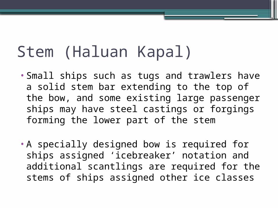
•Small ships such as tugs and trawlers have a solid stem bar extending to the top of the bow, and some existing large passenger ships may have steel castings or forgings forming the lower part of the stem
•A specially designed bow is required for ships assigned ‘icebreaker’ notation and additional scantlings are required for the stems of ships assigned other ice classes


Bulbous Bow• Vessels operating at higher speeds, and those with
high block coefficients, are often found to have a bulbous or protruding bow below the waterline
• to reduce the vessel’s resistance to motion under certain conditions
• From the construction point of view the bulbous bow does not present any great difficulty if this as-pect has been considered when the bulb form is designed

Bulbous Bow• Floors are fitted at every frame space in the bulb, and a
centre line wash bulkhead is introduced when the bulb is large
• Transverses are fitted at about every fifth frame in long bulbs
• Smaller bulbs have a centre line web but not a wash bulkhead; and in all bulbous bows horizontal diaphragm plates are fitted
• Shell plating covering the bulb has an increased thick-ness similar to that of a radiused plate stem below the waterline


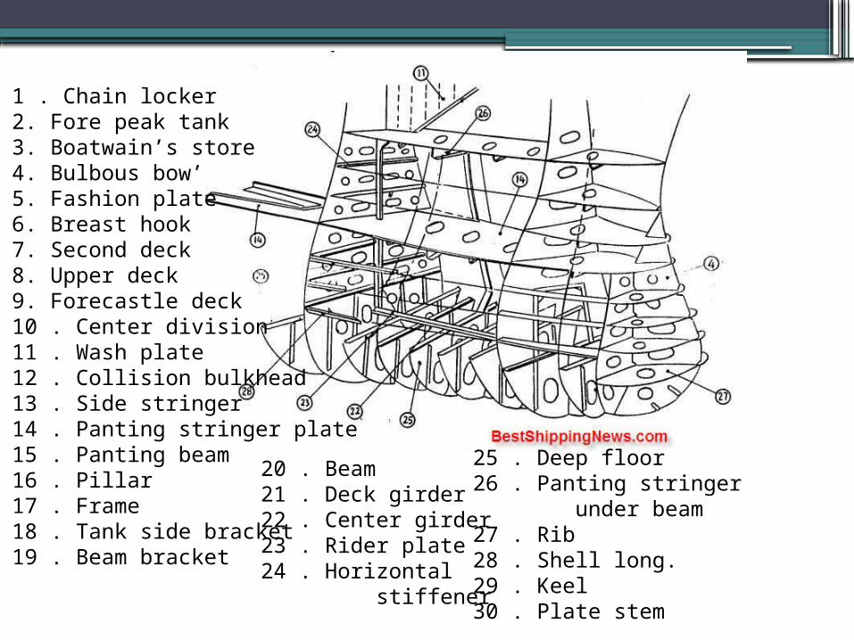
1 . Chain locker2. Fore peak tank3. Boatwain’s store4. Bulbous bow’5. Fashion plate6. Breast hook7. Second deck8. Upper deck9. Forecastle deck10 . Center division11 . Wash plate12 . Collision bulkhead13 . Side stringer14 . Panting stringer plate15 . Panting beam16 . Pillar17 . Frame18 . Tank side bracket19 . Beam bracket
20 . Beam21 . Deck girder22 . Center girder23 . Rider plate24 . Horizontal stiffener25 . Deep floor26 . Panting stringer under beam27 . Rib28 . Shell long.29 . Keel30 . Plate stem
1 . Chain locker2. Fore peak tank3. Boatwain’s store4. Bulbous bow’5. Fashion plate6. Breast hook7. Second deck8. Upper deck9. Forecastle deck10 . Center division11 . Wash plate12 . Collision bulkhead13 . Side stringer14 . Panting stringer plate15 . Panting beam16 . Pillar17 . Frame18 . Tank side bracket19 . Beam bracket
20 . Beam21 . Deck girder22 . Center girder23 . Rider plate24 . Horizontal stiffener
25 . Deep floor26 . Panting stringer under beam27 . Rib28 . Shell long.29 . Keel30 . Plate stem

1 . Chain locker2. Fore peak tank3. Boatwain’s store4. Bulbous bow’5. Fashion plate6. Breast hook7. Second deck8. Upper deck9. Forecastle deck10 . Center division11 . Wash plate12 . Collision bulkhead13 . Side stringer14 . Panting stringer plate15 . Panting beam16 . Pillar17 . Frame18 . Tank side bracket19 . Beam bracket
20 . Beam21 . Deck girder22 . Center girder23 . Rider plate24 . Horizontal stiffener25 . Deep floor26 . Panting stringer under beam27 . Rib28 . Shell long.29 . Keel30 . Plate stem

Chain Locker• A chain locker is often arranged in the position forward of
the collision bulkhead, below either the main deck or the second deck
• It can also be fitted in the forecastle or aft of the collision bulkhead, in which case it must be watertight and have proper means of drainage
• Chain locker dimensions are determined in relation to the length and size of cable, the depth being such that the cable is easily stowed, and a direct lead at all times is provided to the mouth of the chain pipe
• Port and starboard cables are stowed separately in the locker, and the inboard ends of each are secured to the bot-tom of the centre line bulkhead or underside of deck

Construction of Chain Locker• The locker does not as a rule have the same breadth as
the ship, but has conventionally stiffened forward and side bulkheads
• the stiffeners being conveniently arranged outside the locker if possible to prevent their being damaged
• A false bottom may be formed by perforated plates on bearers arranged at a height above the floor of the locker
• Where fitted this provides a mudbox which can be cleaned and is drained by a centre line suction, the bot-tom plating sloping inboard

Construction of Chain Locker• To separate the locker into port and starboard compart-
ments a centre line bulkhead is fitted
• This bulkhead does not extend to the crown of the locker, but allows working space above the two compartments
• Access to the bottom of the locker is provided by means of foot holes cut in the bulkhead, and the stiffeners fitted to this bulkhead are of the vertical flush cope bar type
• The upper edge of the bulkhead is similarly stiffened and may provide a standing platform, with a short ladder leading from the hatch in the deck forming the crown of the locker

Construction of Chain Locker
•Each cable is fed to the appropriate locker compartment through port and starboard chain pipes from the forecastle deck
•These chain pipes or spurling pipes are of tubular construction with castings or other rounded end mouldings to prevent chafing


Hawse Pipe• To provide an easy lead for the cable from the windlass
to the anchors, the hawse pipes must be carefully fitted
• In the past it was not uncommon for a temporary scale model of the relevant fore end structure to be con-structed
• the positions of the hawse pipes experimented with in order to obtain the best chain lead to ensure the an-chor could be raised and lowered smoothly and housed properly
• Today this can be achieved with the CAD hull model

Construction of Hawse Pipe• Tubular hawse pipes are generally fabricated, and
castings are welded at the shell and deck to prevent chafing
• Additional stiffening in way of the hawse pipes is re-quired at the side shell
• On higher speed vessels a recess is often provided in the shell for anchor stowage
• this helps to reduce any drag caused by the stowed anchor and prevents serious damage in the event of a collision


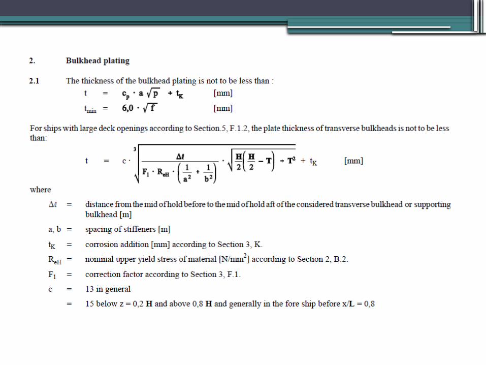
Scantlings of Fore Peak Members
BKI, Vol.2. Sec.8.A.1.2.3
BKI, Vol.2. Sec.9.A.5.2 BKI, Vol.2. Sec.9.A.5.2.1
BKI, Vol.2. Sec.13.B.2
BKI, Vol.2. Sec.13.B.1
BKI, Vol.2. Sec.11.A.2.1. BKI, Vol.2. Sec.11. B.
BKI, Vol.2. Sec.11. B.3. BKI, Vol.2. Sec.12. G.
BKI, Vol.2. Sec.18. E.


Floors, BKI, Vol.2. Sec.8.A.1.2.3


Stem and Plate Stem, BKI, Vol.2.
Sec.13.B.1 and B.2


Panting Beam, BKI, Vol.2.
Sec.9.A.5.2.2


Wash Bulkhead, BKI, Vol.2. Sec.12. G

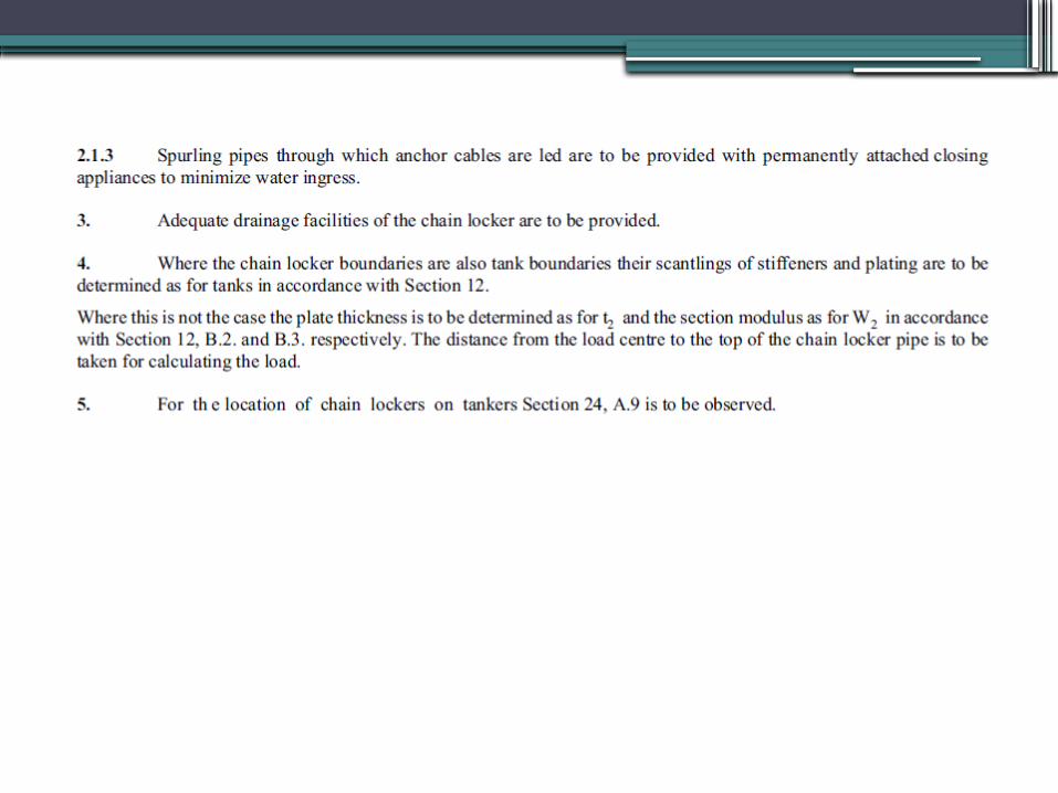
Chain Locker, BKI, Vol.2. Sec.18. E
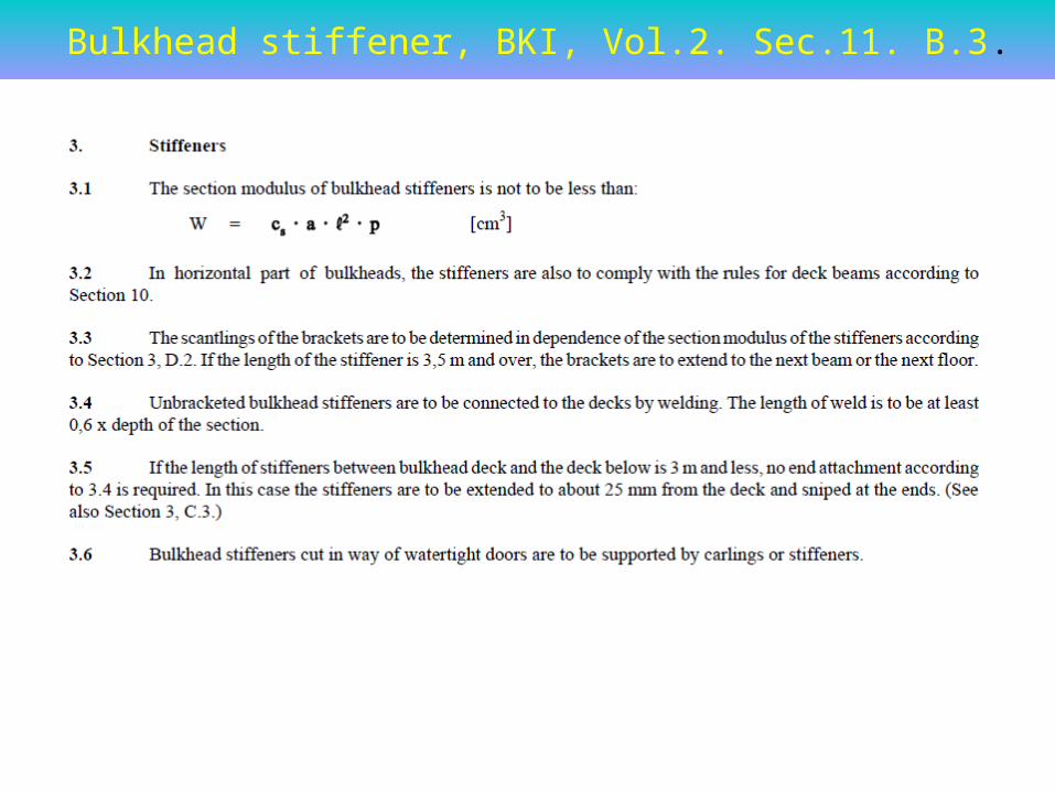
Bulkhead stiffener, BKI, Vol.2. Sec.11. B.3.


Panting Stringer, BKI, Vol.2. Sec.9.A.5.2.1

Collision Bulkhead, BKI, Vol.2. Sec.11.A.2.1. and BKI, Vol.2. Sec.11. B.


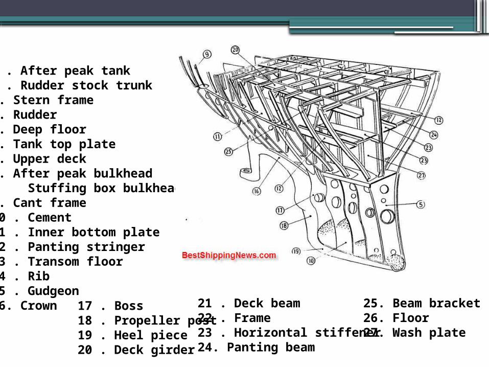
After End Structure• Considerable attention is paid to the stern in or-
der to improve flow into and away from the pro-peller
• The cruiser stern (see Figure 21.1) was for many years the favored stern type for ocean going ships, but today most of these vessels have a tran-som stern (see Figure 21.2)
• A cruiser stern presents a more pleasant profile and is hydrodynamically efficient, but the transom stern offers a greater deck area aft, is a simpler construction, and can also provide improved flow around the stern

Stern Construction• As the cruiser stern overhang may be subjected to large slamming
forces a substantial construction with adequate stiffening is required
• Solid floors are fitted at every frame space, and a heavy centre line girder is fitted right aft at the shell and decks The stern plating is stiffened by cant frames or webs with short cant beams supporting the decks and led to the adjacent heavy transverse deck beam
• Further stiffening of the plating is provided, or adopted in lieu of cant frames, by horizontal stringers extending to the first transverse frame
• Cant frames are not required where the transom stern is adopted, as the flat stern plating may be stiffened with vertical stiffeners (Figure 21.2). Deep floors and a centre line girder are provided at the lower region of the transom stern construction


1 . After peak tank 2 . Rudder stock trunk 3. Stern frame 4. Rudder 5. Deep floor 6. Tank top plate 7. Upper deck 8. After peak bulkhead Stuffing box bulkhead 9. Cant frame 10 . Cement 11 . Inner bottom plate 12 . Panting stringer 13 . Transom floor 14 . Rib 15 . Gudgeon 16. Crown 17 . Boss
18 . Propeller post 19 . Heel piece 20 . Deck girder
21 . Deck beam 22 . Frame 23 . Horizontal stiffener 24. Panting beam
25. Beam bracket 26. Floor 27. Wash plate