kr9700365-39p vz*
TRANSCRIPT

Proceedings of the Second Seminaron the New Fuel Technology
Toward the 2f* Century
KR9700365-39P
vz*
November 25 - 26, 1997
Korea Atomic Energy Research Institute, Taejon, Korea
Korea Atomic Energy Research Institute

The Second Seminar on the New Fuel Technology Toward the 21* CenturyNovember 25 - 26, 1997, KAERI, Taejon, Korea
Programme
November 25,
10 : 00 - 10 : 30
10 : 30 - 10 : 40
10 : 40 - 11 : 00
11 : 00 - 11 : 30
11 : 40 - 13 : 30
•13 : 30 - 14 : 00
14 : 00 - 14 : 30
14 : 30 - 15 : 00
15 : 00 - 15 : 20
•15 : 20 - 15 : 50
15 : 50 - 16 : 20
16 : 20 - 16 : 50
16 : 50 - 17 : 30
1997(Invited Speakers Session)
s~ ^- Registration
7% 3] Opening(Dr. Dong-Seong Sohn, Director, Advanced Nuclear Fuel Program, KAERI)
^'S^l- Welcoming Address(Dr. Seong Yun Kim, President, KAERI)
"ISU^^IL *# *M ^nAdvanced Nuclear Fuel Development Program in KAERI(Dr. Dong-Seong Sohn, Director, Advanced Nuclear Fuel Program, KAERI)
%<$ -$*} Luncheon
Chairman : Young-Woo Lee
Overview of Activities on Pu and Minor Actinides Fuel Researchin JAERI(Yasuo Arai, JAERI, Japan)
Fabrication and Performance of Advanced Fuel and Plans forFuture - Indian Programme(DSC. Purushotham, BARC, India)
Status of Inert Matrix Fuel Program at PSI(Claude Degueldre, PSI, Switzerland)
^ ^ j Coffee Break
Chairman : D-Soon Hwang
Irradiation Behavior of Alloys and Intermetallic Compounds ofUranium(Gerald. L. Hofman, ANL, USA)
The Outlook of Metallic Fuels for Different Types of Nuclear Reactor(Igor Konovalov, VNQMN, Russia)
Thorium Utilization in Thermal Reactors(Kamala Balakrishnan, BARC, India)
£ 4 ^ 3? ' S ^ Discussion & Closing Remarks

The Second Seminar on the New Fuel Technology Toward the 21st CenturyNovember 25 - 26, 1997, KAERI, Taejon, Korea
Programme
November 26,
•9 : 00 - 9 : 25
9 : 25 - 9 : 50
9 : 50 - 10 : 15
10 : 15 - 10 : 30
•10 : 30 - 10 : 55
10 : 55 - 11 : 20
11 : 30 - 13 : 30
13 : 30 - 13 : 55
1997(Korean Papers Session)
Chairman : Chan-Ota Park
Lead-cooled Transmuter Fuel Concepts(Il-Soon Hwang, Seoul Nat! Univ.)
Status of Core Nuclear Design Technology for Future Fuel
(Hyung-Kook Joo, KAERI)
Thorium Fuel Cycle Study for PWR Application
(Myung-Hyun Kim, Kyunghee Univ.)
fl^ Coffee Break
Chairman : Sung-Man Bae
Development of a Computer Code for the Analysis of MOX and
UO2 Fuel
(Yang-Hyun Koo, KAERI)
Effect of Reactor Chemistry and Operating Variables on Fuel
Cladding Corrosion in PWRs
(Moon-Ghu Park, KEPRI)
•?J "il "̂ -M" Luncheon
High U-Density Nuclear Fuel Development with Application of
Centrifugal Atomization Technology
(Chang-Kyu Kim, KAERI)

The Second Seminar on the New Fuel Technology Toward the 21* Century
November 25 - 26, 1997, KAERI, Taejon, Korea
Programme
• Chairman : Kyu-Tae Kim
13 : 55 - 14 : 20 The Effect of Rare Earth Element Additions on Microstructural
Properties and Irradiation Behavior of an Fe-Ni-Cr Alloy for
LMFBR Application
(Jin-Young Park, Fuel Technology Center, KNFC)
14 : 20 - 14 : 45 Design Characteristics of Metallic Fuel Rod on Its In-LMR
Performance
(Woan Hwang, KAERI)
14 : 45 - 15 : 10 Development of KALIMER Fuel Materials
(Chong-Tak Lee, KAERI)
15 : 10 - 15 : 35 Homogeneous Forming Technology of Composite Material and
Its Application to Dispersion Nuclear Fuels
(Soon-Hyung Hong, KAIST)
15 : 35 - 15 : 50 &q Coffee Break
£ Chairman : Chang-Kyu Kim
15 : 50 - 16 : 15 The Influence of the Sintering Atmosphere on Microstructurc of
UO2 Pellet and Properties of Refractories for UO2 Sintering Furnace
(Seung-Jae Lee, Fuel Technology Center, KNFC)
16 : 15 - 16 : 40 Development of Fabrication Process and Equipments for
Advanced-Feature Fuel Pellet
(Young-Woo Lee, KAERI)
16 : 40 - 17 : 05 Development of Coating Technology for Nuclear Fuel by
SHS Method
(Yong Choi, Sunmoon Univ.)
17 : 05 - 17 : 30 ^ ^ £ ^ ^ ^ Discussion A Concluding Remarks
The 2nd Seminar on the New Fuel Technology Toward the 21* Century,
November 25 - 26, 1997, KAERI, Taejon, Korea
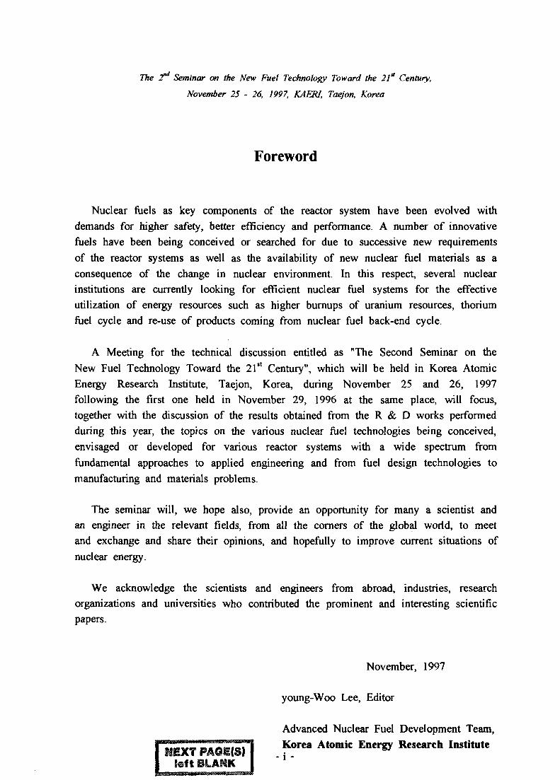
Foreword
Nuclear fuels as key components of the reactor system have been evolved withdemands for higher safety, better efficiency and performance. A number of innovativefuels have been being conceived or searched for due to successive new requirementsof the reactor systems as well as the availability of new nuclear fuel materials as aconsequence of the change in nuclear environment. In this respect, several nuclearinstitutions are currently looking for efficient nuclear fuel systems for the effectiveutilization of energy resources such as higher burnups of uranium resources, thoriumfuel cycle and re-use of products coming from nuclear fuel back-end cycle.
A Meeting for the technical discussion entitled as "The Second Seminar on theNew Fuel Technology Toward the 21st Century", which will be held in Korea AtomicEnergy Research Institute, Taejon, Korea, during November 25 and 26, 1997following the first one held in November 29, 1996 at the same place, will focus,together with the discussion of the results obtained from the R & D works performedduring this year, the topics on the various nuclear fuel technologies being conceived,envisaged or developed for various reactor systems with a wide spectrum fromfundamental approaches to applied engineering and from fuel design technologies tomanufacturing and materials problems.
The seminar will, we hope also, provide an opportunity for many a scientist andan engineer in the relevant fields, from all the corners of the global world, to meetand exchange and share their opinions, and hopefully to improve current situations ofnuclear energy.
We acknowledge the scientists and engineers from abroad, industries, researchorganizations and universities who contributed the prominent and interesting scientificpapers.
November, 1997
young-Woo Lee, Editor
Advanced Nuclear Fuel Development Team,Korea Atomic Energy Research Institute
Ssft BLAI3K I "' "

The Second Seminar on the New Fuel Technology Toward the 21st CenturyNovember 25 - 26, 1997, KAERI, Taejon, Korea
Contents
Overview of Activities on Pu and Minor Actinides Fuel Research
in JAERI 1
Yasuo Arai, JAERI, Japan
Fabrication and Performance of Advanced Fuel andPlans for Future - Indian Programme 7
D S C . Purushotham, BARC, India
Status of Inert Matrix Fuel Program at PSI 23Claude Degueldre, PSI, Switzerland
Irradiation Behavior of Alloys and Inter metallic Compounds
of Uranium 37
Gerald. L. Hofman, ANL, USA
The Outlook of Metallic Fuels for Different Types ofNuclear Reactor 39Igor Konovalov, VNHNM, Russia
Thorium Utilization in Thermal Reactors 41
Kamala Balakrishnan, BARC, India
Lead-cooled Transmuter Fuel Concepts 53Il-Soon Hwang, Seoul Nat'l Univ.
Status of Core Nuclear Design Technology for Future Fuel 55
Hyung-Kook Joo, KAERI
Thorium Fuel Cycle Study for PWR Application 69Myung-Hyun Kim, Kyunghee Univ.
Development of a Computer Code for the Analysis of
MOX and UO2 Fuel 79Yang-Hyun Koo, KAERI
- iii -

The Second Seminar on the New Fuel Technology Toward the 21* CenturyNovember 25 - 26, 1997, KAERI, Taejon, Korea
Effect of Reactor Chemistry and Operating Variables onFuel Cladding Corrosion in PWRs 91
Moon-Ghu Park, KEPRI
High U-Density Nuclear Fuel Development with Application of
Centrifugal Atomization Technology 103Chang-Kyu Kim, KAERI
The Effect of Rare Earth Element Additions on MicrostructuralProperties and Irradiation Behavior of an Fe-Ni-Cr Alloy forLMFBR Application 119
Jin-Young Park, Fuel Technology Center, KNFC
Design Characteristics of Metallic Fuel Rod on Its In-LMRPerformance 121Woan Hwang, KAERI
Development of KALIMER Fuel Materials 133
Jong-Tak Lee, KAERI
Homogeneous Forming Technology of Composite Material andIts Application to Dispersion Nuclear Fuels 149Soon-Hyung Hong, KAIST
The Influence of the Sintering Atmosphere on Microstructure of UO2Pellet and Properties of Refractories for UO2 Sintering Furnace • - • 161Seung-Jae Lee, Fuel Technologty Center, KNFC
Development of Fabrication Process and Equipments for Advanced-Feature Fuel Pellet 177
Young-Woo Lee, KAERI
Development of Coating Technology for Nuclear Fuel bySHS Method 189Yong Choi, Sunmoon Univ
- iv -

The Second Seminar on the New Fuel Technology Toward the 21st CenturyNovember 25 - 26, 1997, KAERI, Taejon, Korea
Invited Papers Session

KR9700366
The 2nd Seminar on the New Fuel Technology Toward the 21st Century,
November 25 - 26, 1997, KAERI, Taejon, Korea
Overview of Activities on Pu and MinorActinides Fuel Research in JAERI
Yasuo Arai and Toshiyuki Yamashita
Japan Atomic Energy Research InstituteTokai-mura, Ibaraki-ken 319-11, Japan
Abstract
Recent activities on Pu and minor actinides fuel research in JAERI is summarized.For oxide fuel, the solid state chemistry on U-Np-Pu-0 system has been investigated.Further, Pu rock-like fuel has been developed from the viewpoint of disposing excessplutonium. For nitride fuel, research on fuel fabrication, property measurements,irradiation behavior and application to pyrochemical reprocessing has been carried out.These studies aim at contributing to the development of advanced fuel cycle andinnovative fuel cycle toward the 21st century.
1. Introduction
Since the foundation for more than forty years, Japan Atomic Energy ResearchInstitute (JAERI) has contributed the civilian use of atomic energy in Japan as a principalnational institute. As far as nuclear fuel research, several types of fuels for LWR, FBR,HTGR as well as research reactors have been investigated, which covers from fabrication,property measurement, irradiation behavior and also reprocessing technology.
In 1994, the Atomic Energy Commission (AEC) in Japan issued the "Long-TermProgram for Research and Development and Utilization of Nuclear Energy". It statesthat the basic national policy is to establish a consistent system of nuclear powergeneration by LWR, to develop nuclear fuel recycle, to diversify the development ofnuclear science and technology, and to reinforce basic research based on security ofsafety.
Following the AEC's program, JAERI has been developing nuclear fuel recycletechnology toward the 21st century. The potential fuel cycle will be characterized asnot only safe and economical one but also strong proliferation resistance, low globalenvironmental burden and efficient utilization of resources. The "advanced fuel cycle"considered is based on the use of fast reactors associated with advanced fuelreprocessing. Power Reactor and Nuclear Fuel Development Corporation (PNC) is incharge of the development of the cycle, but JAERI also has been engaged in the basic
- 1-

research to support the development. On the other hand, JAERI has studied the"innovative fuel cycle" such as double strata fuel cycle proposed in the OMEGA program.The OMEGA program, in which the partitioning and transmutation of minor actinides(MA) are key technology, has been launched to further reduce environmental burdenresulting from geological disposal of high level waste (HLW).
In this paper the outline of the recent Pu and MA fuel research carried out in JAERI issummarized. The activities of Pu and MA oxide and nitride fuels research are shown inthe following chapters. These studies aim at contributing to the development ofadvanced and innovative fuel cycles.
2. Pu and MA Oxide Fuel
2.1 Solid State Chemistry of TRU OxideResearch on solid state chemistry on U-Np-Pu-0 system has been carried out to
complement the database of the oxide fuel cycle. It concerns rather basic field, whichcovers from the phase relations, crystal structure to electrical, thermal andthermodynamic properties on the system.
Phase relations of UO2-U3Q8-NPO2 and NpO2-PuO2 systems at elevated temperatureswere investigated by high-temperature X-ray diffractometry and thermogravimetry inorder to determine the phase region of the fluorite solid solution [1]. In the former case,as the analogy to the UO2-ThO2 system, it was found that the fluorite single phase existswithin the region of UO2-NpO2-U~0.4Np~0.6O2.27-U4O9 over the whole Np/(U+Np)ratio. On the other hand, very narrow single-phase region was confirmed over thewhole Pu/(Np+Pu) ratio in NpO2-PuO2 system.
With regard to crystal structure, the effects of the cation contents on the latticeparameters of (Ul-yMy)02.oo (M=Pu, Th, La) solid solutions were investigated [2].The samples were carefully prepared to keep the homogeneity and stoichiometriccomposition. On the contrary to the French results showing the deviation from theVegard's law [3], any anomalous behavior was not observed in this case. The change inlattice parameters was analyzed based on the rigid ion sphere model and the speculationwith stoichiometric composition agreed well with the experimental results. Theseresults suggested that the present solid solutions investigated could be considered almostideal.
The electrical conductivities of (U,Pu)02+x and (U,Np)O2+x solid solutions weremeasured by four inserted wires method as a function of temperature and oxygen partialpressures as well as the composition of the solid solutions [4,5]. Different stages in theoxygen partial pressure dependence of electrical conductivity were observed, from whichthe defect structure of the solid solutions was discussed. The activation energy ofelectrical conduction was also derived from the temperature dependence to 1273 K.From the experimental results for (U,Np)02+x it was found that Np always exists in +4state in the solid solution and the defect structure of the solid solution is identical withthat of UO2.
Thermal expansion of AnO2 (An= Th, U, Np, Pu) and (U,Np)O2 and (Np,Pu)O2 solidsolutions was investigated by high-temperature X-ray diffractometry in controlledatmosphere up to 1300 K [6,7]. The object of the study is not only to determine the
- 2 -

linear expansion coefficients (a) but also to find out the relation between a and themelting temperature and estimate high-temperature specific heat capacity from a. Thelinear expansion coefficients of the above compounds have been proposed. Thepreliminary results suggested that the present method is a possible way to estimate high-temperature specific heat capacity, although the understanding of the relating mechanicalproperties, such as the adiabatic compressibility and Griineisen constant, is neededhereafter.
2.2 Pu Rock-like FuelPlutonium rock-like fuel (ROX fuel), which has a multiphase structure and is
composed of inert matrix and plutonium oxide, has been developed from the viewpointof disposing excess plutonium [8]. Plutonium in the fuel will be completely burnt inconventional LWR core and the spent fuel could be disposed without any furtherprocessing. The advantage of the fuel exists in little reproduction of fissile elements andits geological stabilities.
Up to now, basic study of ROX fuel material and a preliminary irradiation test havebeen carried out besides reactor physics study. Phase relations of ZrO2(Y,Gd)-Al2O3-MgO and ThO2-Al2O3-MgO systems were studied on simulated fresh and spent fuels.According to the results, it was found that Pu is solidified into the fluorite phase as asolid solution. In the simulated spent fuels, the lanthanides were distributed in hiboniteand fluorite phases, the alkaline earth elements mainly in hibonite phase. Noble metalsformed the alloy with Mo. The geological stability of all phases formed in the simulatedspent fuel is well known. The leaching characteristics of the fuels were also examined.Further, the disk samples of A12O3(65 mol%)-MgO(10 mol%)-ZrO2(Y,G)(15 mol%)-PuO2(10 mol%) and A12O3(65 mol%)-MgO(10 mol%)-ThO2(15 mol%)-PuO2(10 mol%)were fabricated and subjected to the irradiation in JRR-3M for 4 cycles. The firstresults of the post irradiation examinations (PIEs) were obtained in this year.
3. Pu and MA Nitride Fuel
3.1 Why Nitride?It is well known that actinide mononitride has several characteristics suitable for
advanced fuel for fast reactors; high thermal conductivity, high melting temperature, highheavy metal density, good compatibility with stainless-steel cladding and sodium coolant,mutual solubility among actinide mononitrides and so on [9]. The use of nitride fuel infast reactors will lead to wider safety margins in designing reactor core and efficientactinide breeding or burning. So JAERI considers the solid solution of actinidemononitrides to be probable fuel in the advanced fuel cycle.
On the other hand, JAERI has proposed the concept of the double strata fuel cycleconsisting of the power reactor fuel cycle and the partitioning-transmutation (P-T) cyclein the OMEGA program [10]. Two dedicated transmutation systems have been studiedfor the moment; one is an Actinide Burning Reactor (ABR) and the other is anAccelerator Driven System (ADS). In both cases, fuel material will be the solidsolution of mononitrides containing minor actinides such as Np and Am as a principalcomponent from thermal and neutronic consideration
- 3 -

Nitride fuel cycle mentioned above will be combined with pyrochemical reprocessingin the scenario [11]. Since actinide mononitride is a good electrical conductor andactinides and most of fission products will behave almost same as in metallic fuel inchloride molten salt, the electrorefining process developed for metallic fuel cycle in USA[12] will be applied to nitride fuel with minor modification. It is well known that one ofthe drawback of nitride fuel is the radiological problem of C-14 produced from N-14.So it is preferable to use N-15 enriched nitrogen in the fuel cycle. This is anotherreason that we choose pyrochemical reprocessing process in which recovery of N-15 willbe done with relative ease, although nitride fuel itself is compatible with conventionalPUREX process.
3.2 Nitride Fuel DevelopmentIn JAERI, research on fuel fabrication, property measurements, irradiation behavior
and application of nitride fuel to pyrochemical reprocessing has been carried out forabout a decade. Actinide mononitride such as UN, NpN and PuN and their solidsolutions such as (U,Np)N, (Np,Pu)N and (U,Pu)N are prepared by carbothermicreduction of the dioxides [13,14]. The experiments focused on establishing theeffective manner for preparing high-purity mononitride without loss of actinides. Twomethods of carbothermic reduction were developed; one is the one-step reaction in N2-H2 mixed gas stream and the other is the two-step reaction of reduction in N2 streamfollowed by removal of excess carbon in N2-H2 mixed gas stream. The residual oxygenand carbon contents could be lowered to less than 500 ppm by both methods. Sinteringcharacteristics of nitride powders were also investigated and the sintered pellets havebeen used for fuel property measurements and irradiation tests. Further, internalgelation method for preparing nitride microspheres has been developed.
Thermal conductivity and vaporization behavior of nitride fuel have been investigated.Thermal conductivity was derived from thermal diflfusivity measured by laser flashmethod. Thermal conductivities of actinide mononitride and their solid solutionsshowed a similar temperature dependence that they gradually increase with temperaturefrom 680 to 1600 K. Thermal conductivity decreased from UN-side to PuN-side inorder, especially in UN-rich region in (U,Np)N, in NpN-rich region in (Np,Pu)N and inUN-rich region in (U,Pu)N [15]. Further, the effects of porosity and oxygen impuritycontents on the thermal conductivity of (U0.8P0.2)N were examined [16,17].Vaporization behavior was investigated by high-temperature mass spectrometry.Actinide bearing gaseous species detected in the measurements were only monatomicAn(g) except for a trace of AnO(g). Vapor pressure of An(g) decreased in order ofPu(g) over PuN, Np(g) over NpN and U(g) over UN. In the series of experiments, thefree energy of formation on NpN was proposed by analyzing temperature dependence ofthe vapor pressure of Np(g) over NpN [18]. The activities of each component in thesolid solutions such as (U,Pu)N and (Np,Pu)N were calculated from the vapor pressuresand the present results suggested some deviation from ideality [19,20]. Further,unusual vaporization behavior of Am(g) over reactor-grade PuN was observed [21].
Irradiation tests of (UO.8PuO.2)N fuel started in 1990 to demonstrate the fuelperformance. Up to now the irradiation of four He-bonded mixed nitride fuel pins inJMTR has been completed [22]. Thermally stabilized fuel pellets fabricated by use oforganic pore former particles were used in the campaigns. Several basic information
- 4 -

such as fission gas release and swelling rates could be obtained from the results of PIEscarried out in a-g hot cells with Ar gas atmosphere. On the other hand, irradiation testsin fast test reactor JOYO started in 1994 aiming at burnup of 4.5%FIMA under the jointresearch with PNC [23]. In this case PIEs of two (UO.8PuO.2)N fuel pins will becarried out in both JAERI and PNC.
With regard to application to pyrochemical reprocessing, the apparatus forelectrorefining study of nitride fuel were equipped in 1995-1996. Two electrorefinersand a cathode processor were installed in the glovebox with high purity Ar gasatmosphere. Following the preceding demonstration of the electrolysis of UN [24], thepreliminary experiments using Np and Pu started in the beginning of this year. Theelectrochemical behavior in AnC13-LiCl-KCl (An = Np, Pu) system and distribution ofAn in LiCl-KCl-Cd(Bi) system are being studied under the joint research with CentralResearch Institute of Electric Power Industry (CRIEPI) [25]. The direct electrolysistest of NpN and PuN is to be carried out in this year focusing on the anodic and cathodicbehaviors.
4. Summary
Recent activities on Pu and MA fuel research in JAERI is overviewed.Thermophysical and thermodynamic properties on U-Np-Pu-0 and U-Np-Pu-N systemshave been clarified to contribute to the development of advanced fuel cycle andinnovative fuel cycle such as partitioning and transmutation. The irradiation tests ofROX and (U,Pu)N fuels developed are also in progress to demonstrate the fuelperformance. Electrorefining of nitride fuel in chloride molten salt is studied to apply topyrochemical reprocessing. Further, the design study of "Americium high-temperaturechemistry cell" is under way for research on Am, which is one of the key elements in thefuture fuel cycle. Domestic and international collaboration is indispensable for furtherdevelopment.
Acknowledgment
The authors wish to express their thanks to Dr. M. Hoshi, Director of Department ofChemistry and Fuel Research in JAERI, and T. Muromura, Deputy Director ofDepartment of Chemistry and Fuel Research in JAERI, for the interest in this study.
References
[1] T. Yamashita, N. Nitani, K. Ohuchi, T. Muromura, T. Tsuji, H. Inagaki, T. Kato, J.Alloys and Compounds, 213&214 (1994) 375.
[2] T. Tsuji, M. Iwashita, T. Yamashita, K. Ohuchi, Int. Conf. Actinides'97, Baden-Baden, Germany, Sep. 21-26,1997, to be published in J. Alloys and Compounds.
[3] M Beauvy, J. Nucl. Mater., 188 (1992) 232
- 5 -

[4] T. Fujino, T. Yamashita, K. Ohuchi, K. Naito, T. Tsuji, ibid, 202 (1993) 154.[5] T. Yamashita, K, Ohuchi, T. Tsuji, T. Kato, M. Ochida, M. Iwashita, Int. Conf.
Actinides'97, Baden-Baden, Germany, Sep. 21-26, 1997, to be published in J.Alloys and Compounds.
[6] T. Yamashita, N. Nitani, T. Tsuji, T. Kato, J. Nucl. Mater., 247 (1997) 90.[7] T. Yamashita, M. Muto, T. Tsuji, Y. Nakamura, Int. Conf. Actinides'97, Baden-
Baden, Germany, Sep. 21-26, 1997, to be published in J. Alloys and Compounds[8] N. Nitani, H. Yokoi, T. Yamashita, T. Ohmichi, T. Matsui, T. Muromura, J. Nucl.
Mater., 247 (1997)59.[9] H. Blank, in "Materials Science and Technology", vol. 10A, Nuclear Materials,
VCH,Weinheim(1994).[10] T. Mukaiyama, M. Kubota, T. Takizuka, T. Ogawa, M. Mizumoto, H. Yoshida,
Proc. Int. Conf. on Evaluation of Emerging Nuclear Fuel Cycle Systems(GLOBAL'95), Versailles, France, Sep. 11-14, 1995, p.l 10.
[11] T. Ogawa, S. Yamagishi, F. Kobayashi, A. Itoh, T. Mukaiyama, M. Handa, R.G.Haire, ibid, p.207.
[12] Y.I. Chang, Nucl. Technol, 88 (1989) 129.[13] Y. Arai, S. Fukushima, K. Shiozawa, M. Handa, J. Nucl. Mater., 168 (1989) 280.[14] Y. Suzuki, Y. Arai, Y. Okamoto, T. Ohmichi, J. Nucl. Sci. Technol., 31 (1994) 677.[15] Y. Arai, K. Nakajima, Y. Suzuki, Int. Conf. Actinides'97, Baden-Baden, Germany,
Sep. 21 -26, 1997, to be published in J. Alloys and Compounds.[16] Y. Arai, Y. Suzuki, T. Iwai, T. Ohmichi, J. Nucl. Mater., 195 (1992) 37.[17] Y. Arai, M. Morihira, T. Ohmichi, ibid, 202 (1993) 70.[18] K. Nakajima, Y. Arai, Y. Suzuki, ibid, 247 (1997) 33.[19] Y. Suzuki, A. Maeda, Y. Arai, T. Ohmichi, ibid, 188 (1992) 239.[20] K. Nakajima, Y. Aral, Y. Suzuki, Int. Conf. Actinides'97, Baden-Baden, Germany,
Sep. 21-26, 1997, to be published inJ. Alloys and Compounds.[21] T. Ogawa, T. Ohmichi, A. Maeda, Y. Arai, Y. Suzuki, J. Nucl. Mater., 224 (1995)
55.[22] Y. Arai, Y. Suzuki, T. Iwai, A. Maeda, T. Sasayama, K. Shiozawa, T. Ohmichi, / .
Nucl. Sci. Technol., 30 (1993) 824.[23] Y. Arai, Y. Suzuki, T. Ohmichi, M. Handa, S. Shikakura, S. Nagai, N. Mizoo, Proc.
Int. Conf. on Fast Reactors and Related Fuel Cycles (FR'91), Kyoto, Japan, Oct.28-Nov. 1, 1991, Vol. Ill, paper 1-22.
[24] F. Kobayashi, T. Ogawa, M. Akabori, Y. Kato, J. Am. Ceram. Soc., 78 (1995)2279.
[25] O. Shirai, T. Iwai, Y. Suzuki, Y. Sakamura, H. Tanaka, Int. Conf. Actinides'97,Baden-Baden, Germany, Sep. 21-26, 1997, to be published in J. Alloys andCompounds.
- 6 -

KR9700367
The 2r Seminar on the New Fuel Technology Toward the 21* CenturyNovember 25 - 26, 1997, KAERI, Taejon, Korea
Fabrication and Performance of Advanced Fuels andPlans for Future - Indian Programme
DSC Purushotham
Bhabha Atomic Research CentreBombay-400 085 India
Abstract
The closed fuel cycle philosophy adopted by India and the large thorium reservesavailable forms the basis of our planned 3-stage nuclear power programme.Utilisation of Pu in fast reactors is the primary goal and interim use in the BWRsand PHWRs is being pursued through the technologies developed for achieving thesegoals. Development work relating to Th-U233 system is in progress to enable therealisation of the large energy potential of the thorium reserves.
1. Introduction
In India, we have somewhat limited reserves of uranium and fairly large reserves ofthorium, which are the basic materials of the nuclear power programme. With thisresource position, the Department of Atomic Energy has planned a 3 stage programmefor the growth of nuclear power in our Country. The first stage has commenced withPressurised Heavy Water Reactors (PHWRs) using natural uranium oxide as fuel.Plutonium (Pu) produced in these reactors is planned to be used in the second stagefor its multiplication through breeders running on Pu-U238 cycle.
Towards the end of the second stage, as the U238 gets consumed, production ofU233 from thoria will be taken up. In the 3rd stage, the U233 produced in thesecond stage breeders will be used for running reactors based on U233-Th cycle. Useof Th in the 3rd phase would enhance the energy potential to the extent of 6 timesover the U238-Pu cycle and is expected to be the mainstay of our energy scenariofor the next century.
As such, for the present, our nuclear power generation is through a series ofPHWRs of 220 MWe capacity using Nat.UO2 fuel, expect for two BWRs of ourTarapur Atomic Power Station (TAPS) which use LEU fuel. The closed fuel cyclephilosophy adopted by us yields Pu intended essentially for the fast reactorprogramme, for which a beginning has been made by the starting of the Fast Breeder
- 7 -

Test Reactor (FBTR) at Kalpakkam in the mid-80s'. The FBTR is fuelled with mixedcarbide of composition (PuO.7 U0.3)C. Further, as an interim measure for utilisation ofPu due to delays in the fast reactor programme, we have started a programme onMOX fuel, initially for use in our BWRs, and to be followed by a recycleprogramme in the PHWRs. Also, as part of our strategy for utilisation of Th, anAdvanced Heavy Water Reactor (AHWR) is under development which would useMOX with ThO2- UO2 to generate most of the energy from U233, bred in-situ fromthorium.
This paper deals with some of the aspects of fabrication and experience gained withthe MOX fuel for the BWRs, mixed carbide fuel for the fast reactor, and plans forthe future which include the PFBR, technologies such as co-reprocessing of spent fuelwith modifications to the PUREX process etc.
2. MOX Fuels
MOX fuels are planned for use in our BWRs and PHWRs, and these aspects arediscussed in this section.
2.1 MOX Fuel for BWRs
With the background of international experimental irradiations and programmes onMOX fuel, we also examined the feasibility of recycling Pu, initially to be taken upin the BWRs to utilise the nuclear fuel resources to the maximum extent possible. Westudied the operation of our BWRs at TAPS with a mixed core consisting of MOXand LEU fuel assemblies. The preliminary studies established feasibility, although tobe limited to l/3rd of the core for MOX fuel. Experimental irradiations[l] ofprototype MOX fuel elements were carried out in our research reactor CIRUS,wherein modest burnup targets were achieved without any fuel failures. Subsequently,detailed studies on all aspects of Pu recycle were undertaken and design of a MOXfuel assembly to substitute the LEU assemblies partially was evolved. Analyses of fuelbehaviour under transient conditions were also performed. The fuel assembly design,which has the same mechanical design of the LEU assembly [Fig.l(a)] is shown inFig.l(b) and consists of an array of 6 x 6 rods, with one water rod in the spacercapture rod position. An All-Pu fuel rod assembly[2] was chosen to maximise the Pucontent in the assembly, which could also satisfy the local peaking criteria. 3compositions of MOX are used in the assembly, designed without burnable poisons.Table-I gives some of the nuclear parameters of the MOX and LEU fuel with Gd.
Based on the earlier work, a flow-sheet for MOX fuel manufacture (Fig.2) wasselected and a plant was constructed at Tarapur where the manufacturing of MOXfuel assemblies has been in progress. The first 6 assemblies produced here have beenundergoing irradiation in the two reactors. Two assemblies loaded at the first instancein one of the reactors have so far accumulated a burnup of 10,000 MWd/Te (atpresent in the second cycle), and the other four loaded in the second reactor have
- 8 -

crossed a bumup of about 3,500 MWd/Te (in the 1st cycle). The in-pile performanceof these assemblies has been quite satisfactory so far. The reactors employ 3-batchcycling of 18 months, with the average burnup for LEU fuel at 20,000 MWd/Te. ForMOX fuel, a discharge burnup limit of 15,000 MWd/Te has been set in order to limitthe reactivity due to the absence of Gd. It is now planned to step up scale ofproduction and introduce more such MOX fuel assemblies at this Station.
Further studies are in progress for the introduction of burnable poison rods in thisMOX fuel assembly to enhance the reactivity and facilitate 18 month cycleoperation[3]. This would also be one of the steps enabling enhancement of Pu contentin the reactor core.
2.2 MOX for PHWRs
A study has been under way to realise the extension of fuel burnup from 7,000MWd/Te obtainable with nat.UO2 fuel used in our PHWRs to about 10,500 MWd/Teby using a small addition of Pu to the central 7-rods of the 19-rod PHWR fuelbundles[4]. This scheme has major advantages to the back-end of the fuel cycle whilefacilitating interim utilisation of Pu in the larger numbers of our PHWRs. The fuelbundle design evolved, based on this study, is shown in Fig.3 and some of thefeatures of this design are shown in Table-H This scheme also makes it possible tointroduce Th in these reactors on a once-through basis. A batch of such MOX fuelbundles are scheduled for fabrication and study of in-pile performance.
3. Fast Reactor Fuels
The on-going programme on the mixed carbide fuel for the Fast Breeder TestReactor(FBTR) and plans for fuelling the Prototype Fast Breeder Reactor (PFBR) withmixed oxide fuel, are discussed in this Section.
3.1 Mixed Carbide Core of FBTR
The Fast Breeder Test Reactor (FBTR) located at Kalpakkam and commissioned inthe mid-80s' is a sodium-cooled loop-type reactor, fuelled with the mono-carbide(PuO.7UO.7)C. The reactor has operated, to date, up to 12.5 MWth, with a smallcarbide core comprising of 26 fuel sub-assemblies. This advanced fuel has performedsatisfactorily with 320 W/cm peak linear heat rating. Recently, a maximum fuelburnup of about 40,000 MWd/T has been achieved and irradiation is continuing. Thecentral fuel assembly, at a burnup of about 25,000 MWd/T (15 d pa), was dischargedfor post irradiation examination early this year. On completing visual examination ofthe 61 pin fuel sub-assembly, dimensional measurements were carried out and fuelpins were dismantled. Some of these were subjected to leak testing, ultrasonic testing,metrology, eddy current testing, X-ray radiography, etc.[5]. Cut sections of the pinswere subjected to metallography and Fig.4 shows some typical cross-sections. Therewas no swelling or bulging of the sheath in the fuel region of the sub-assembly. Pin
- 9 -

diameters were within the original limits and there was no clad deformation. Eddycurrent testing indicated that the stack length had increased. Further examinationrevealed that the pellet-clad gap was closing due to cracking and swelling of the fuel.Space is still available for accommodating further swelling of the fuel. However, theswelling rate will be reducing due to lowering of centre-line temperature of fuel dueto gap closure. This fuel has been designed for a burnup of 50,000 MWd/T and isexpected to attain this target in a satisfactory manner.
At this stage, an enhanced core has been under consideration and it is planned tohave a larger core with about 60 fuel assemblies of (PuO.55 U0.45)C composition toenable 40 MWth operation of the reactor. All preliminary studies, including irradiationtrials, have been completed and fabrication of this core with characteristics given inTable-IH is in progress at BARC.
3.2 Prototype Fast Breeder Reactor (PFBR) Fuel
A 500 MWe pool-type sodium-cooled PFBR is under detailed design, which isplanned for construction shortly and generation of power during the next decade, atKalpakkam. The chosen fuel is mixed oxide, and its design data is given in Table-TV.The 2-zone core fabrication is scheduled for commencing by about 2005. Annularpellet design is being adopted, with D-9 alloy as the cladding material. The referenceroute for fuel fabrication is the pellet-in-tube process, the feed material preparationbeing through the sol-gel process, for which developmental activities have been underway at our Radio-Chemical Labs, for some time now. Experimental irradiation of thisfuel is to be taken up shortly and preparatory fabrication development work iscurrently in progress at the MOX plant at Tarapur.
4. U233 based fuels
Thorium/Thorium oxide rods have been irradiated in our research reactors overmany years, and separation of U233 has been carried out on campaign basis in ourreprocessing facilities, in a separate line, set up for this work. A1-U233 alloyfabrication route, for plate-type fuel, has been developed at our RadiometallurgyLaboratory.
4.1 Plate-Type Fuel
A 30 KWt U233 fuelled, light water research reactor KAMDSIL located in the lineof hot cells for the PIE of fast reactor fuels, has been brought into operation for thepurpose of neutron radiography (mainly fast reactor fuel) and activation analysis. Thisreactor uses plate-type fuel through ingot-melting route, followed by roll-bonding androll-swaging[6] stages for the picture-frame assembly preparation.
4.2 Pellet Fuels

For the remote fabrication of pellet type U233-containing fuels the pellet-impregnation technique has been studied[7]. Here, ThO2 pellets sintered to about 80%theoretical density, are impregnated in uranyl nitrate solution, dried and sintered at1700oC for obtaining the desired density. The ThO2-UO2 forms a solid solution. Theimpregnation and subsequent processing is carried out in shielded enclosures. As analternate to this process, sol-gel micro-sphere pelletisation may be adopted. Here,dust-free, free-flowing microspheres of the mixed oxide fuels are produced through thegelation route, calcined, pelletised and sintered to high density pellets[7]. This processis also well-suited for automation and remotisation.
4.3 Advanced Heavy Water Reactor Fuel (AHWR)
The AHWR design is under way and is being planned for development in the nextfew years. The reactor has several passive safety features and will enable thoriumutilisation, by energy generation largely through in-situ burning of U233. The AHWRfuel cluster will have 52 pins arranged in a square array. The MOX pins in thiscluster will be surrounded by ThO2 pins, and Zircaloy-2 will be the claddingmaterial. This reactor is of great interest to our power programme and thedevelopment work relating to various aspects is planned to be pursued vigorously.
5. MOX through Co-Processing Route
As a proliferation-resistant and technologically innovative approach for closing thefuel cycle, we are considering reprocessing and recycle of U and Pu together, withouttheir individual separation, for the LWR spent fuel. The residual enriched U and Puin the spent fuel can be utilised for fabrication of MOX for the PHWRs. Thismethodology would involve the co-processing and recovery of U and Pu together bythe PUREX process, co-conversion of U and Pu product mix into their oxides, andfabrication of the PHWR-MOX fuel.
The proposed scheme[8] for the co-processing of Pu and U is shown in Fig.5.Essentially, the decontamination cycles are repeated till the fission productdecontamination is achieved to desired levels, and the partitioning stage is manipulatedto strip Pu fully and requisite amount of U will be made to follow this Pu so thatthe stripped product has 95% U and 5% Pu. This would be the master-feed forfurther dilution with U, and further conversion to MOX using co-precipitation/directdensification/sol-gel process as suitable, can be effected. Different aspects of thisscheme - technical and economic - are under examination in this regard.
6. Conclusions
For the Indian power programme with the closed fuel cycle philosophy, plutoniumis a resource material and technologies to utilise it in fast/thermal cycles are beingpursued. The utilisation of our large thorium resources needs exploitation oftechnologies for the Th232-U233 system, for which a beginning has been made. The
- 11 -

implementation of these schemes alone can help to meet the large demand for nuclearpower needed by us in the coming decades.
7. References
[1] DSC Purushotham et al. Mixed Oxide Fuel Development for the Indian NuclearPower Programme',IAEA - TCM on "Recycle of Plutoium and Uranium inWater Reactor Fuels", Windermere (UK), July 3-7, 1995.
[2] PD Krishnani Lattice Calculations for TAPS-MOX Fuel Assembly1, BARCInternal Report ThPD/385 (1993)
[3] AK Anand et al. Towards the use of 100% MOX Core in BWRs1, Global-97,Tokyo, October 1997.
[4] Pu Recycle in RAPS', BARC Internal Report (September 1987)[5] Report on PIE carried out on FBTR Fuel Assembly - IGCAR Internal Report.[6] GJ Prasad et al. Fabrication Development of Plate Fuels for Indian Research
Reactors', IAEA-TCM on Research Reactor Fuels, Seoul, October 1996.[7] Kamala Balakrishnan et al. ,'Thorium Utilisation in Indian Power Programme'.[8] Recovery of U/Pu by Co-Processing in PUREX Process', Private
Communication.
- 12 -

Table-I. Nuclear Features of MOX
No.
1.
2.
3.
4
5.
6.
7.
i.
9.
10.
11.
12.
13.
14
15
16.
parameter
K*
K«,
K.
K.
LPF
1(uscc)
1(Msec)
a
A
(Control)
AK/K(Control)
Fuel Temp.Coeff.(x 10VC)
Mod.Tcmp.Coeff.(x 10-7°C)
ModTempCoefT(x lOV'C)
Void Coeff(x 10° BOCper % void)
Void Cocff.(xlO'EOCpxr % void)
JCore conditions
Cold, no xenon and0 GWD/ST bumup
Hot, xenon and0 GWD/ST bunrop
Hot^icnon, 4O*/o voidand 0 GWD/ST bumup
Hot,xenon,40% and10 GWD/ST burnup
Hot,xenon,40% voidand 0 GWO/ST buniup
Cold and 10 GWD/S'fbumup
Cold end 10 GWD/STbumup
Cold and 0 GWD/STbumup
Cold and 10 GWD/STbumup
Cold, no xenon and0 GWD/ST burnup
Cold, no xenon 40%void
585-1000 °C fueltemp, 0 GWD/ST
200-286 °C modtemp, BOC
200-286 °C mod.lemp, EOC
20%-40% void
2(l%-40% void
PUELTYP15MOX LEU fuel with Gd
1.264
1.217
1.179
1060
1 172
24.9
30.1
0.0O41
0.0042
1.168
0.242
-2.55
-2.70
-227
-1 38
-1.24
1.162
1.119
1099
1.081
1 189
316
382
0.0077
0.0061
1.187
0.274
-228
-228
-1.91
-1 11
-1.07
- 13-

Table-II. Some Features of MOX-7 Fuel Bundle for PHWR
1 FUEL BUNDLE DESIGN : MOX-7
2. BUNDLE POWER DISTRIBUTION[From Center to Periphery]
a) Start of irradiation
b) 10 GWd/Tc burn-up
3. FUEL/BURNUP (MWd/Te)
a) Inner Zone
b) Outer Zone
c) Average
4 MAXIMUM BUNDLE POWER (kw)
5 MAXIMUM CHANNEL POWER
6. REACTIVITY WORTH ANDADJUSTER RODS
Inner 7 rods with0.4% PuO:
Outer 12 rods withNat.UO2
1.032 1 175 0.910
0.910 0.969 1.023
Nat U/11,000
Mox-7/10,200
10,700
422 in Nat.U bundle
3.11MW
13 2milli-K
- 14-

Table-Ill. Characteristics of FBTR-Mark-II Fuel
1. Composition - 5 5% Pu C - 45% UC
2. U + Pu - 94 - 95%; Pu - 52.9 + 0.0%- 0.2%
3 C - 5 . 0 3 % Max.
0 -- 5,000 ppm
N - 2,000 ppm.
M2Ca-5-15%
4. Pellet Dia. : 4.18 ±0.05 mm
Density (%T.D) : 86+1"2
Linear mass : 160 ±0.04 (g/cm)
5. Pin; Outer Dia . 5.1 ± 0.03 mmI.D : 4 36 mmLength : 531.5+ 0.4 mm
- 1 2
Bow ; 2 in 1,000
Fissile Column length : 320 ± 1 5 mm
Spacer wire pitch ; 90.0 ±4.0 mm
We.ld TIG, 110% penetration.
- 15 -

Table-IV. Major Specifications of Mixed Oxide Fuel for PFBR
1.
2.
3.
4.
5
6.
7.
8.
9.
PuO2 Content (Wt.%)(Zone I/Zone 2)
Diameter (mm)
Central HoleDiameter (mm)
Length (mm)
Density (% T.D)
Linear Mass (g/cm)
0/M
No isolated Pu-rich clusters =
21/27
Solid5.55 ±0.04
-
10
87.0 ±1.0
2.33±0.08
1.95
> 100 micron in diameter
Complete solid solution between UO2 & PuO2.
Annular5.56 ± 0 04
1.70 ±0.10
10
96.0 ±1.0
2.33 ±0.88
1.95
- 16-

LEU Assembly
L=1.6X U235
M=2.1% U 2 3 5
H=2.6% U
Fig. l(a)
235
MOX Assembly
L=0.9% Pu
M=1.55% Pu
H=3.25% Pu
Fig. 1 LEU & MOX Assembly Design

U. 0/M.Impurities,Moisture
N I C C
Density. U. Puanalysis,
Dissolution,Micros tructure,
oc—Autoradiography
Inspection
•UOs PuOe
Weighing Weighing
Mixing/]
Precompoctioa
Granulation
Compaction
Density.Physical Integrity
Sintering
Centrelaoa Grinding
Washing/Drying
Diameter, Density,Physical Integrity
Vacuum Degasaing
Impurities, 0/M,Eq. Hi
Stacking
Bottom End PlugWelded ZircaloyTubes, Plugs kPlenum Springa
Vacuum Degassing
loading
Top Plug Welding
Decontamination
Assembly
Packing
Storage
Shipment
Pu, botopic,Impurities,
Moisture
Metallography
Visual, He leak.Radiography,
•B -̂Scan, Metrology,Weld Cham,
Cover Gga Analysis
Inspection,Channel Testing,
etc.
Fig. 2 Flow Sheet for MOX Assembly Fabrication
with Quality Control Points
- 18 -

(M)(M)
1(M)1®(M)
(R)®
1(H)1(H)(M)
(M)
i®
s®(M)
LEU Assembly
L=i.8X u 2 3 5
U-ZAX U235
H=2.6X U236
MOX Assembly
L=O.OX Pu
M=1.5SX Pu
H=3.25X Pu
^r
-UO g RODS
-0.4% Pu Oa
MOX FUEL BUNDLE FOR PHWR
Fig. 3 MOX Fuel Bundle Design
- 19-

Ceiilrr ojjh.iilr fnliwni. MM W/cnt.2 5, (MM M117///
>17«/> iiffixsih column. 210 Wan,Iti.OOOMWtt/i
-) ('nine i'! liinli1 i-i'lniiiii. .mil 117cm, 1.7) I lift ofjhxil* rolimm. 7 HI \Y/nnISMOOMWil/i
Fig. 4 Microstructure of irradiated mixed (Puo.7Uo.3)C
- 2 0 -

U(IV) scrub
1IBUiORC)
Pu TraceU 7 l t f l
Strip
1CP(AQ)U
2V> Cycle: U
ADU
LWR Fuel-« Kg Pu/T
J Dissolution
foed(AQ)Pu 216 8.1U 360 g/l
130% IBP Extn
HAP(ORO)Pu (>.480g/l
U 82.5 £>]
Scrub
HSP(ORG)Pu 0.480^1U 80 g/1
Additional ScrubAnd/Or
Additional Co-dc-coiHuiniruiiion
c>'clc for improvedDFtromFps. «-.:lmCi/l
HSP Snip
i t rub Sm|>\viilUJ(lV')*in OX to 1 M II*
A: I
' i.Adjusi Acidity lorat). Dconlcni)
( U 95°/,. Pn 5%)
MOX Fewl(AQ)Pu 1.928-1U 37 g/|
JUSU.'I'uADJUSTMENlFOR MOX
CO-PROCHS-SMNK;
ROUTES1 Solgel2 Oxalaie-'Oxidc3. Denilrauon4. AU-PuC5.
Fig. 5 Scheme for Co-processing of Pu and U
-21 -MEXT
Sett PLANK

KR9700368
The 2nd Seminar on the New Fuel Technology Toward the 21* Century,
November 25 - 26, 1997, KAERI, Taejon, Korea
Status of The Inert Matrix Fuel Program at PSI
Guido Ledergerber, Claude Degueldre,Uwe Kasemeyer, Alexander Stanculescu, Jean Marie Paratte and Rakesh Chawla
Paul Scherrer Institut, CH-5232 Villigen PSI, Switzerland
AbstractIncineration of plutonium by a once-through cycle in LWRs utilising an inert matrix based
fuel may prove to be an attractive way of making use of the energy of fissile plutonium andreducing both the hazard potential and the volumes of the waste. Yttria stabilised zirconiaforms a solid solution with oxides of rare earth elements (e.g. erbium, cerium) and someactinides. The small absorption cross section, the excellent stability under irradiation, and theinsolubility in acids and water recommends this material as an inert matrix. Neutronicscalculations with erbium as burnable poison show that these compositions would be optimalfrom the reactivity point of view. A fuel element with an improved reactivity behaviour over itslife cycle has been designed for possible introduction into a heterogeneous LWR core.
1 Motivation
The inventories of spent uranium fuel, and hence of plutonium generated by commercialnuclear power plants, are continuously increasing. In Europe, reprocessing of uranium basedfuel and MOX fabrication are industrial activities which will develop into a competitive optionfor the back-end of the nuclear fuel cycle. Recycling MOX with the aim of radio-toxicityhazard reduction with emphasis on the long lived isotopes is investigated in the context ofmultiple recycling schemes based on fast reactors. Direct disposal of uranium fuel elements isunder evaluation, but it implies the intrinsic problem of burying rather large volumes of solublematerial with a high content of fissionable isotopes. For the elimination of excess plutonium byits transformation into an inaccessible waste form, zirconia based inert matrix fuel (IMF) forenergy production in a LWR is a feasible option studied at PSI [1],[2]. The chopped claddingsmight be seen as the source of zirconium for this matrix material, further reducing the wastevolume and concentrating the radio-toxic materials.
2 Fuel Matrix
Zirconium oxide is a promising candidate as inert matrix because it may be stabilised by rareearth oxides in a single phase solid solution which offers attractive properties for a nuclear fuel.In this material, rare earth oxides stabilise the phase in a cubic structure, and the stabilisedzirconia is then comparable to UO2 in MOX fuel. In the suggested fuel material, the stabilisedzirconia fluorite-type phase will be the host phase for plutonium, other actinide elements orfission products. Binary cubic mixtures Z1O2-YO1.5 form solid solutions with numerousdopants from room temperature to about 3000 K [3]. Little is known on the properties of
- 23 -

zirconia based ceramics, and on their behaviour under irradiation. Some early studies reporteddata on zirconia lattice expansion [4], thermal conductivity changes [5], and mechanicalproperty changes [6]. It was also observed that during neutron irradiation of uranium dopedzirconia, the phase transforms to cubic when the neutron fluence increases [7]. More recently,Clinard [8] studied the behaviour of stabilised zirconia under neutron irradiation and showedthe presence of ordered inclusion arrays. All of this information indicates that these zirconiabased materials have a relatively stable behaviour under irradiation.
For estimating the in-pile behaviour of zirconia based fuel, the behaviour of both inert matrixand simulated fuel materials is being studied under specific types of irradiation. Since fissionproducts such as Xe are known to cause considerable material damage, the stability of theseceramic materials has been assessed under Xe irradiation utilising both high and low energyparticles.
2.1 Material Preparation and Analysis
The selected route for material preparation is aqueous co-precipitation of the nitrate saltssolution mixture by ammonia. This wet preparation method was adapted for the fabrication of asimulated fuel material (ZrQgs.x.yYxEroojM^O] ^ . ^ with M = Ce, U or Th as analogue of Pu(x= 0.10-0.15, y= 0.07-0.10). Subsequent drying, crushing, pelletising and sintering at 1875 Kwas carried out for pellet preparation. The relative density of these material samples was about95%. X-ray diffraction was used for phase interpretation and determination of second phaseformation. As an example Figure 1 shows that the quaternary material forms a single solidsolution. Lattice parameter measurements where applied for characterisation and the
Figure 1: XRD Spectrum and Structure of Pellet (SEM Micrograph) of a
(Zro.7Yo. 15Ero.o5Ceo. i )°i .9 Sample
2000
1800
1600 J
1400
1200
1000
800 1
600
400
200
20 60 80 100Diffraction angle
- 24 -
120" r-ii
140

determination of theoretical densities. Specific samples for measurements were obtained bycutting the pellet using a diamond saw.
2.2 Thermal Conductivity Analysis
Thermal conductivities of zirconia based inert matrix and analogous fuel materials weremeasured and modelled [9]. Measurements were performed using the laser flash method andsystematically applied to binary, ternary and quaternary systems including zirconia, yttria, erbiaand ceria or thoria. Measurements were carried out from room temperature up to 1300K.Thermal diffusivity results for simulated fuels are given in Figure 2 and compared to non-irradiated and irradiated UCX Thermal conductivity was calculated using theoretical values forspecific heat capacity and was also modelled taking into account the effect of dopants on thelattice parameter of the cubic solid solution and the oxygen vacancy size and concentration [9].Experimental and lattice parameter values are compared prior to full justification of the results.In the temperature range from 300 to 1000 K, the thermal conductivity of the single phase solidsolution with yttria, erbia and ceria as analogues of fuel material was confirmed to be about 2W-TTT'-K"1, a value similar to stabilised zirconium oxide with similar dopant concentrations.
0.035
J
bTo
0.030
0.025
0.020
0.015
0.010
0.005
\
• * -
\
sXv
"• m—•— s—A~fc-*k
200 500 1000 1500
Temperature (K)
2000
Figure 2: Thermal Diffusivity for (Zr075Y0 10Er005Me0,\Q)OX 925 Me = Ce (•)or Me = Th (±), for Uranium Oxide (•) and for High Burn-up UraniumFuel (•) with 63 MWd/kg UO2
In addition, inert matrix sample conductivity was measured up to 2200 K. It was striking tonote the large conductivity increase around 1500 K, reaching 3 W-m'-K"1 at 2200 K. Thesesamples presented, however, lower conductivities at room temperature (about 1.5 Wm'-K"1).Recently, comparable thermal conductivity values were obtained by oscillating scanningdifferential calorimetry for the same material (Figure 3). Energy transfer in this transparentmatrix must, however, be discussed on the basis of both photonic and phononic conductivities.Based on the phononic conductivity, an annular pellet design to reduce the centre linetemperature has been proposed [2].
- 2 5 -

~ 5XL
E
o•o8
<D
.Y0.10 .Efoce)• (ZrO7, Y 0 1 5 , Er 0 0 5 , Ce01)O., 9
(2rO7, Y 0 1 s , Er0 05. Tho. i) O 1 9
•uranium oxide according HWR-469
Conductivity wascalculated withCP(T)ofZrO2
(Touloukian and Buyco)
•) I i i i I i i i i I i i i i I i i i i I i i i i I i i i i I i i i i I i i i i I
500 750 1000 1250 1500 1750 2000 2250
Temperature [K]
Figure 3 : Thermal Conductivity for (Zr075Y0 10Er005Me0.loKh .925with Me = Ce or Me = Th, for Uranium Oxide and forHigh Burn-up Uranium Fuel with 63 MWd/kg UO2
(Reference for High Burn-up Data: HWR-469 OECD Halden Reactor Project)
System: (Zr,., .Yx,Er )O2,+,y'~2-(x+y)/2System:
3,5 -
•T 3,0 4
"g 2,5 H
*>t 2 0™
1.5 -i
1,0
0% Er5% Er10% Er
ODSC
I I I I I I I0 5 10 15 20 25 30
cone, of Y and Er (in oxide) [At%]
(Z ro6R.Yo,.Eroo7.Ce0J019,6i
I(#)
J L
3,5
3,0
2,5
1,5
1,0
10 15cone, of Ce or Th (in oxide) [At%]
Figure 4 : Comparison of Thermal Conductivity Values Determined by OscillatingDifferential Scanning Calorimetry and Laser Flash Method[(#) indicates a measurement with a bad contact in the equipment]
-26-

2.3 Behaviour under Irradiation
The inert matrix and simulated fuel materials were irradiated using an analytical electronmicroscope with a low energy Xe injector at the Japanese Atomic Energy Research Institute(JAERI) and using the HVEM-Tandem Facility at Argonne National Laboratory (ANL).
For electron microscopy, trepanning disks of 3 mm diameter with a thickness of 10-20 |im inthe centre part were made by ultrasonic cutting and dimpling. Perforation was made by thinningwith a 3 keV Ar+ ion beam. With the electron microscope, amorphization and defect clustersdue to ion thinning were not observed on the inert matrix samples. In all samples cubic solidsolutions were determined. One as fabricated sample (with thoria included) presented locallyamorphous phases (about 10%) produced in the tri-join boundary spaces.
Observations and irradiation experiments for (Zr0g5Y0 ]0Er005)O] 925 with and without 10%CeO2 at JAERI were performed in an JEM electron microscope equipped with an ionaccelerator. The beam of 60 keV Xe ions provided a flux of 51012 Xe-cnr2^-1. The irradiationswere carried out at room temperature and at 925 K accumulating relatively large doses,simulating fission damage under light water reactor conditions (Figure 5).
The thickness of the sample observed with an electron microscope was about 50 nm.Irradiation performed at the two temperatures demonstrated that for a dose of 1.8 10l6Xecm~2,no amorphization was observed. The penetration depth of the Xe ions in the inert matrixirradiated with 60 keV Xe ion was estimated to about 15 nm by the TRIM-95 code.
After ion irradiation, the volume swelling of the specimens was estimated from the totalbubble volume which was measured from bubble densities and average bubble radius. Thevolume swelling was estimated to be about 0.19 % at room temperature and about 0.72 % at925 K, respectively.
Simulated fuel samples (Zr075Y010Er005Th0 ]0)Oj 925) were prepared to investigate themicroscopic behaviour of the material under high energy irradiation (1.5 MeV). TEM sub-samples were prepared by mechanical grinding and ion milling at the University of NewMexico. The thickness of those samples was of the order of 100 nm and the irradiation tookplace in the HVEM-Tandem Facility. The material was irradiated with an ion dose rate ofSAlO^Xe-cm'V1, to doses of 2.0-10l6Xecm2 with high energy Xe ions. Irradiation wascarried out at 20 K with a liquid helium stage, because previous experiences on ZrO2 haveshown that the phase is very resistant to amorphization, but that amorphization might occur atsufficiently low temperatures at which defect recovery could be suppressed. Some observationswere carried on-line. (Figure 6)
At a fluence of 21016 Xe-cm"2, a high density of dislocation loops was observed, and the sizeof the loops ranged from 20 to 60 nm. Detailed TEM analysis after ion irradiation did notreveal any amorphization even near the grain boundaries. According to a full cascade TRIM-95calculation (using Ed = 60 eV), the damage in the middle of the electron transparent TEM foil(100 nm in depth) reached 25 dpa (deplacement per atom) at full ion dose.
The results of all examinations indicate that the irradiation temperature (20 K) is still too highto destroy the crystal structure of stabilised zirconia [10]. Compared to the stability of UO2under energetic irradiation conditions [11], the proposed IMF seems to be much more stable.
-27 -

Figure 5 : Process of Formation and Growth of Defect and Bubbles in
(Zro.85Yo.ioEro.O5)°i.925 during Irradiation with 60 keV Xe Ions of 5 1 0 l 2 X e c n r2-S'' at 650°C. Courtesy Dr. Hojou, JAERI, Tokai-mura
1.5-10MXe-cm-' 6 1014Xecm2
(defect clusters were formed) (bubbles were formed)6-1015Xecm2 1.8 1016 Xe cm2
LG43-5/KI82/24.10.97
Figure 6 : Examination of Defects on a (Zr0 7 5Y0 10Er005Th0 10)O, 925 Sample
during Irradiation with 1.5 MeV Xe Ions of 2-1016Xe-cm"2 at 20 KCourtesy Prof. Ewing, Uni New Mexico
LG43-&KI82/24.10.97
-28 -

3 Fuel Assembly Design
Based on scoping cell calculations [1] addressing the basic reactor physics characteristics(e.g. depletion dependent reactivity variation, temperature and void coefficients, reactivitycontrol) of IMF, a promising candidate was identified, with ZrO2 being the inert matrix inwhich the PuO2 fuel is embedded, and Er2O3 the burnable poison. This fuel was included in aninternational benchmark exercise aiming at data and methods validation [12].
In a second step, whole-core three-dimensional neutronics analyses were performed [13], [14]to assess the operational, safety-related, and - last but not least - plutonium consumptioncharacteristics of present-day PWR core designs fuelled with the aforementioned uranium-freefuel. Within the scope of these studies (i.e. equilibrium cycle situations, homogeneousuranium-free assembly design), the results obtained have been very encouraging. They indicate,for a present-day 1 GWe PWR, the feasibility of a 100% uranium-free fuelled four-region corewith a cycle length of over 300 efpd. Its plutonium consumption capabilities (in terms of totalplutonium) are approximately twice as high as in the case of 100% MOX-fuelled cores, i.e.60% to 70% of the initial plutonium inventory depending on whether reactor-grade orweapons-grade plutonium is considered. At the same time, the operational characteristics (e.g.reactivity variation with burnup, and power peaking) of the uranium-free cores are very similarto those of conventional present-day UO2 fuelled ones. A discussion of the safety-relatedparameters, on the other hand, asks for a more discerning approach. While the fuel temperaturefeedback reactivity effect (Doppler coefficient) in the uranium-free (reactor-grade) core isapproximately half the value (in absolute terms) of that for the conventional UO2-core, themoderator temperature coefficient is very similar, and the shutdown margin (reactivity marginat hot zero-power conditions) is even larger - always when comparing the uranium-free withthe conventional UO2-core. The bottom line to date is that, although no cliff edges are expectedbased on the results for safety-related parameters obtained from static neutronics analyses,detailed transient studies are necessary to strengthen the safety case for the uranium-free cores.
The results presented in this paper summarise the main findings of the third step in thephysics design efforts towards the goal of enhanced plutonium consumption in present-dayPWRs fuelled with uranium-free plutonium fuel. In these studies, we have looked at "real-lifesituations" which ask for "transition configurations" in which loadings with mixed UO2 anduranium-free assemblies must be considered. The plutonium composition of the lattercorresponds to reactor-grade fuel with a burnup of approximately 40 GWd/t and 5 yearscooling time.
The problems faced when introducing uranium-free assemblies into a UO2-assembliesenvironment are similar to those encountered in the case of MOX fuel [15]. Figure 7 shows thedistribution of the relative power densities for both a MOX fuel (Figure 7 (a)), and an uranium-free assembly (Figure 7 (b)). In both cases the special assemblies are homogeneous andsurrounded by standard UO2-fuel. It is worthwhile mentioning that, with the exception of theoutermost corner pin (for which the spectral effect of the neighbouring UO2 - elements isextreme), the spectral impact of the uranium, zone on the plutonium bearing assembly isstronger in the case of the MOX fuel assembly than in the case of the uranium-free one.
-29 -

1.4-1
o•
(a)
Figure 7 : Relative power densitydistributions of a MOX (a) and anuranium-free plutonium fuel assembly(b) surrounded by standard uraniumoxide fuel.
1.5
£
(b)
- 3 0 -

As a matter of fact, the spectral effects are "felt" well into the MOX assembly, while, in theuranium-free case, they hardly influence the power distribution beyond the first pin row. Thismay be explained by the fact that, on the one hand, the plutonium content in the uranium-freefuel assembly is approximately 50% higher than in the MOX one (thus having a moredetermining influence on the spectral properties), and, on the other hand, to the enhancedthermal absorption rates, at beginning of life, in the uranium-free assembly due to the presenceof the burnable poison. Based on the results presented in Figure 7, an optimised heterogeneousdesign of a 15 x 15 uranium-free fuel assembly has been obtained (Figure 8, V* symmetry). Itssimplicity, when compared to advanced MOX fuel assemblies [15], is apparent. Thedistribution of the relative power densities for this subassembly surrounded by standard UO2-assemblies at a depletion stage corresponding to 350 efpd is given in Figure 8 (right). Thisburnup state - corresponding approximately to the end of the first cycle - has been chosenbecause it is the most demanding one (the supplementary gadolinia in the correspondingpoisoned rod at the outermost corner position is depleted at this stage). As can be seen, thepower distribution is very satisfactory (maximum form factor not exceeding 1.16).
To determine the influence of the introduction of the proposed uranium-free fuel assembly onthe core parameters of a standard UO2- fuelled PWR, three-dimensional full core analyses of apresent-day 1 GWe PWR containing 4 and 12 such fuel assemblies have been performed. Themain results are summarised below:
- loading 4 uranium-free assemblies does not alter any of the operational characteristicsof the PWR core, as compared to the standard UO2 -fuelled case;
- in case 12 uranium-free assemblies are considered, the beginning of life boronconcentration is lower than in the standard UO2 -fuelled core.
The results summarised in Figure 9 quantify the effects on the power distribution. In Figure9 (a), relative nodal power densities are indicated for the beginning of cycle situation of astandard UO2-fuelled present-day 1 GWe PWR (maximum form factor not exceeding 1.52).The four uranium-free fuel assemblies have been loaded symmetrically into the peak powerlocations. The power distribution results for the beginning and end (gadolinia depleted) of cyclesituations are shown in Figure 9 (b) and Figure 9 (c), respectively. As can be seen, satisfactorypower distributions are attained, with form factors below 1.54 and 1.33 for the beginning andend of cycle, respectively. The results presented so far strengthen the case for a gradualintroduction of uranium-free fuel assemblies having the design proposed in Figure 8 into apresent-day 1 GWe PWR. They indicate that loading 4 to 12 such assemblies permits toenvisage fuel management schemes compatible with current operational requirements (i.e.cycle length, boron concentration, etc.). However, when considering the plutoniumconsumption capabilities of such a core, caution is due with respect to using results obtainedfor 100% uranium-free PWR loadings [14]. Clearly, additional studies are necessary to define adetailed fuel management strategy beyond the 4-12 uranium-free fuel assemblies considered inthe present study, and towards 100% uranium-free fuelled cores. Nevertheless, based on theresults obtained for 100% MOX and uranium-free PWR-cores (about 430 kg/GWea and1090 kg/GWea plutonium consumption rate, respectively [14]), conclusions with regard to theplutonium consumption capability of uranium-free fuelled PWRs as compared to MOX fuelledones can be drawn.
- 31 -

1
1/4 Symmetry
Pu / Er / Zr-oxide0.95/0.3/5.0 [g/cc]Pu / Er / Zr-oxide0.8 / 0.4/ 5.0 [g/cc]Pu /Er /Gd/Zr-oxide0.7/0.3/0.3/5.0 [g/cc]
Guide Tube
Water Hole
LG43-3S/KIB2/1.07 97
Figure 8: Optimised design and relatedpower density distribution for anuranium-free plutonium fuel assemblysurrounded by standard uranium oxidefuel.
The 1 GWe PWR considered consumes thesame amount of plutonium when loaded with4 or 12 uranium-free fuel assemblies, as itwould with 10 or 30 MOX assemblies,respectively. In other terms, if a PWR loadedwith a 1/3 loading of MOX assemblies can beconsidered as operating in a "self-generatingmode", the same would be achieved with aslittle as a 1/8 loading of uranium-free fuelassemblies. The uranium-free fuelled PWRhas an edge over the 100 % MOX core alsowhen comparing the minor actinides (MA)production. Per unit amount of plutoniumconsumed, this is almost a factor of 2 lower inthe former case [14].
• 32 -

1.52-.C1
I"a*ft?
10
(a)
Figure 9 : Relative powerdistributions derived from 3Dfull-core calculations for astandard uranium oxidefuelled PWR at BOC (a), andfor the same PWR with 4uranium-free plutonium fuelassemblies loaded onto thepeak power locations at BOC(b) and at EOC (c).
\
(c)
-33 -

4 The Fuel Assembly as Waste Form
An assessment of the radio-toxicity risk associated with the waste obtained from uranium-free fuelled PWRs, and a comparison with MOX has been carried out on the basis of thenuclide inventories in the discharged fuel. No barrier effects of the waste repository areconsidered. The radio-toxicity risk values are thus obtained by multiplying the nuclideactivities in the discharged fuel by the corresponding effective ingestion dose conversionfactors derived from the ICRP Publication 61 data on the limits on intake of radionuclides byworkers [16]. Table 1 summarises the core inventories of the considered PWR variants atbeginning and end of life.
PWRfuelled with:
UO2
100 % MOX
100 % U-free
Pu
0
5.2
7.7
Core inventory [103
BOL
U I MA
84.5 | 0
80.0 | 0
0 | 0
Pu
1.0
3.5
3.3
kg]EOL
U
80.7
76.7
0
MA
0.09
0.26
0.38
Table 1: Core Inventories at Beginning (BOL) and End of Life (EOL) of the Different1 GWe PWRs (1300 EFPD Residence Time)
A meaningful comparison of the radio-toxicity hazard potential has to include also the reactorsystems needed to feed the plutonium-consuming reactor. On the basis of the results given inTable 1, it is concluded that 5.2 and 7.7 standard UO2 -fuelled 1 GWe PWRs are necessary tofeed one 100% MOX and one uranium-free 1 GWe PWR, respectively.
PWR
fuelled with:
UO2
100 % MOX
100 % U-free
Radio-Toxicity hazardgiven in [106Sv/GWea] after
103a I 104a | 105a i 106a
l'270 257 ! 14.1 | 2.33
899 162 | 7.38 j 1.80
670 i 109 | 5.20 | 1.69
Table 2 : Radio-ToxicityHazard Potential for theDifferent 1 GWe PWRsScenarios Considered
Accordingly, the radio-toxicity hazard potential given Table 2 and Figure 10 considers thewaste coming from 5.2 PWRs for the 100 % MOX, and from 7.7 PWRs for the uranium-freefuelled case, on top of the waste produced by the respective plutonium burning reactor.Obviously, the plutonium unloaded from the UO2-PWRS to feed the respective burners is not tobe directly considered as waste. It contributes to the radio-toxicity only indirectly, i.e. afterbeing recycled in the burners.
To help to put the radio-toxicity hazards into perspective, a line at 5-106 Sv/GWea is drawnin Figure 10. This value corresponds to the asymptotic toxicity hazard of the natural uranium(0.7 % 235U) mass needed to generate 1 GWe per year. As can be seen, the additional radio-
- 34 -

101 0
&oa
ssCOI
107
106
Standard uranium fuel
Pu recycled as MOX I •
fission products I " \ \
Pu -recycled as IMF • \ v
Fresh uranium
102 103 104
109
107
toxicity hazard due to the fissionproducts from actuallygenerating this power fallsbelow this level after less than400 years. The radio-toxicityassociated with the actinides(plutonium and minoractinides), on the other hand,reaches this limit only afterlOO'OOO - 200'000 years,depending upon the fuel typeconsidered. When comparingthe radio-toxicity hazard in theperiod from 1-103 to 1106 years(Table 2), the uranium-free caseis the most favourable (a factorof approximately 2 lower thanfor the UO2 -fuelled core), withthe MOX case indicating hazardpotentials about 25 - 30%higher.
107 However, when assessing thepotential of the proposeduranium-free fuelled PWRs, itmust be borne in mind that theinsolubility of this inert matrix
fuel in water and acids, on the one hand, and the important reduction of the waste volumes byreprocessing with the utilisation of the chopped claddings, on the other, offer importantadvantages over UO2- and MOX- fuelled cores.
Storage time [a]
Figure 10 : Comparison of Hazard Potential
5 REFERENCES
[ 1 ] J.M. Paratte and R. Chawla . On the physics feasibility of LWR plutonium fuelswithout uranium, Ann. Nucl. Energy, 22, 471-481 (1995).
[2] C. Degueldre, U. Kasemeyer, F. Botta and G. Ledergerber. Plutonium incineration inLWR's by a once-through cycle with a rock-like fuel, Mat. Res. Soc. Symp. Proc. 412(1995) 15-23.
[3] D.-J. Kim. Lattice parameters, ionic conductivities and solubility limits in fluorite-structure MO2 oxide (M = Hf, Zr, Ce, Th, U) solid solutions, J. Am. Ceram. Soc. 72(1989) 1415-1421.
[4] R. Berman, M. Bleiberg and W. Yeniscavich. Fission fragment damage to crystalstructures. J. Nucl. Mater. 2 (1960) 129-140.
[5] ORNL: Solid State Division, Semiannual Progress Report for Period Ending February28, 1955. ORNL-1852 Oak Ridge National Laboratory, TN, USA.
- 3 5 -

[6] J. Crawford and M. Wittels. Radiation stability of non-metals and ceramics. SecondUnited Nations International Conference on the Peaceful Uses of Atomic Energy,Geneva, Switzerland, 5 (1958) 300-310.
[7] ORNL: Solid State Division, Semiannual Progress Report for Period Ending August1961. ORNL-3213, Oak Ridge National Laboratory, TN, USA.
[8] F. Clinard, D. Rohr and W. Ranken. Neutron-irradiation damage in stabilised ZrO?, J.Am. Ceram. Soc. 60, 5-6 (1977) 287-288.
[9] C. Degueldre, M. Takano, T. Ohmishi, K. Fukuda, H.P. Heimgartner and T. Graber.Energy transfer and thermal conductivity through inert matrix and nuclear fuelanalogous materials, JAERI-Research Report 97-087 (1997).
[10] C. Degueldre, P. Heimgartner, G. Ledergerber, N. Sasajima, K. Hojou, T. Muromura,J. Wang, W. Gong and R. Ewing . Behaviour of zirconia based fuel material under Xeirradiation, Mat. Res. Soc. Symp. Proc. 439 (1997) 625-632.
[11] K. Hayashi, H. Kikushi and K. Fukuda. Radiation damage of UO2 implanted with100 MeV iodine. J. Alloys and Compounds, 213/214 (1994) 351-353.
[12] J.M. Paratte, H. Akie, R. Chawla, M. Delpech, U. Kasemeyer, J. Kloossterman, R.Konings, C. Lombardi, A. Mazzola and H. Takano. Benchmark Comparison of LWRFuel Cells with Uranium Free Fuels, Proc. Global'97 (1997) 1129-1135.
[13] U. Kasemeyer, R. Chawla, P. Grimm and J.M. Paratte. Conceptional Study for a PWRCore Employing Uranium-Free Plutonium Fuel, Proc. Int. Conference on Evaluationof Emerging Nuclear Fuel Cycle Systems, Versailles (1995).
[14] U. Kasemeyer, R. Chawla, P. Grimm and J.M. Paratte. Comparison of PWR CoreCharacteristics for 100% Pu-containing Loadings, submitted for publication toNuclear Technology (1997)
[15] P. Urban, D. Bender and G. Schosser. Siemens - Competency in Design and Deliveryof MOX Fuel Assemblies. The Nuclear Engineer, Volume 37, No. 6, 183 -186.
[16] P.W. Philippen, F. Lypsch, P. Lizana and H. Riitten. Gefahrdungspotential radioaktiverAbfalle, ATW40 Heft 6 (1995) 384 - 389.
- 36 -

The Second Seminar on the New Fuel Technology Toward the 21st CenturyNovember 25 - 26, 1997, KAERI, Taejon, Korea
Irradiation Behavior of Alloys and Intermetallic Compounds*
of Uranium
by Gerald. L. Hofman, ANL, USA
This paper was not available at the time of publication.
I KEKTtef t BIAUK

The Second Seminar on the New Fuel Technology Toward the 21st CenturyNovember 25 - 26, 1997, KAERI, Taejon, Korea
The Outlook of Metallic Fuels for Different Types of
Nuclear Reactor*
by Igor Konovalov, VNIINM, Russia
* This paper was not available at the time of publication.
- 39 - I mxrI i©f t BLANK

KR9700369
The T Seminar on the New Fuel Technology Toward the 21st Century,
November 25 - 26, 1997, KAERI, Taejon, Korea
THORIUM UTILISATION IN THERMAL REACTORS
Kamala BalakrishnanBhabha Atomic Research Centre
Mumbai - 400 085. INDIA.
Abstract
It is now more or less accepted that the best way to use thorium is in thermal reactors.This is due to the fact that U233 is a good material in the thermal spectrum. Studies ofdifferent thorjum cycles in various reactor concepts had been carried out in the early daysof nuclear power. After three decades of neglect, the world is once again looking atthorium with some interest. We in India have been studying thorium cycles in most ofthe existing thermal reactor concepts, with greater emphasis on heavy water reactors. Inthis paper, we report some of the work done in India on different thorium cycles in theIndian pressurized heavy water reactor (PHWR), and also give a description of thedesign of the advanced heavy water reactor(AHWR).
1. Introduction
In the initial days of nuclear power, conventional wisdom decreed that reactors basedon the fissioning of U235 alone will not be able to provide all the energy requirements ofthe world, and a large body of work on thorium was carried out in those days. With time,however, power growth slowed down in the developed world, the light water reactorbecame very successful and captured 85% of the nuclear power market, and thenuclear community put thorium on the back burner.
India, which has vast deposits of thorium and limited uranium resources, has drawn upits nuclear power program to consist of three phases, of which the third and final phaseenvisages the use of thorium on a large scale. In preparation for the decisions to be takenfor the third stage, we studied the use of thorium in all of the existing reactor concepts.
2. Energy Potential of Thorium
Before looking at the different possible options, we take a look at the energy potentialof thorium in thermal reactors, which is very much greater than that of uranium. Thisfact is often forgotten these days, mainly due to the glut of low cost uranium in the
- 41 -

Western world. Table 1 emphasizes this point by showing the mount of energy that canbe extracted from 1000 tone of natural uranium using three different systems.
3. Existing Concepts
Thorium cycles were analyzed in the following systems
(a). Light water breeder reactor (LWBR).
(b). The high temperature gas cooled reactor (HTGR).(c). The molten salt breeder reactor (MSBR).(d). The aqueous suspension heavy water reactor.(e). The open lattice heavy water reactor.(f). The pressurized heavy water reactor (PHWR).(g). The advanced heavy water reactor (AHWR).(h). The source driven reactor.
The best resource utilization of thorium was, not unexpectedly, in the MSBR. Thenext best system turned out to be the heavy water reactor. Since the work horse of theIndian nuclear power program is the PHWR, we have examined various ways of usingthorium in the PHWR.
The PHWR is basically a system that was optimized for uranium. As such, the use ofthorium in this system is basically a form of retrofitting. It is interesting to see what itwould be like if the reactor itself were to be optimized for thorium. This has led to thedesign of the Advanced Heavy Water Reactor (AHWR).
This paper then consists of two parts. In the first, we describe various ways of usingthorium in the PHWR. In the second, we provide some insight into the design of theAHWR.
4. Description of the PHWR
The Indian PHWR is a tube type reactor using heavy water as both coolant andmoderator. The coolant is physically separated from the moderator by being containedinside the pressure tube where it is maintained at high temperature and pressure. Themoderator heavy water is at relatively low temperature and is unpressurized.
The reactor core consists of 306 pressure tubes arranged along a square lattice of22.86 cms pitch. The fuel pins and the coolant are contained within these pressure tubes.The fuel is a cluster of 19 rods and is divided into bundles of 49.5 cms length. Everychannel contains 10 such bundles in the active portion of the core. Refuelling is done bysimply pushing out eight bundles from a channel on one end, while eight fresh bundlesare inserted from the other end.
-42 -

5. Thorium cycles in PHWR
In broad terms, three kinds of thorium fuel cycles are possible in the PHWR. Thesecan be named as the self-sustaining equilibrium thorium cycle (SSET), the highburnup, high conversion ratio cycle, and the once through thorium cycle (OTT).
5.1. The self-sustaining equilibrium cycle
In this cycle, the fuel in the equilibrium stage is thorium-U233. The initial enrichmentof U233 in the thorium is so adjusted that the quantity of U233 recovered from the spentfuel will be exactly sufficient to provide the enrichment for the reload fuel. This cycle cangive a discharge burnup of 11000 - 12000 MWD/T. This burnup is too low for a cyclethat calls for reprocessing and possibly remote fabrication of fuel. The dischargeburnup can be increased by adding a small amount of makeup fissile material to the freshfuel.
Figure 1 shows the energy production in an SSET cycle with U235 makeup. Sincethere is no net destruction of U233, it can be assumed that all the energy is comingfrom the destroyed U235. We see that as the discharge burnup increases, the energyextracted reduces. Also shown in the same figure is a similar curve for low enricheduranium, and we can see the immense advantage one gets by going for the thorium self-sustaining cycle.
5.2. The high conversion ratio high burnup cycle
The major problems of the SSET are the need for reprocessing, and for U233fabrication. The high burnup thorium cycle avoids these. This cycle would be ofparticular interest to those countries which subscribe to the concept of direct disposalof spent fuel, because high burnup enables one to shrink the spent fuel inventory. Highburnup is of course, equally possible with leu too, but the advantage of thorium over leulies in the fact that for the same high discharge burnup, the initial fissile contentrequired is lower with thorium fuel. Figure 2 shows discharge burnup as a function ofinitial U235 content for leu fuel and for thorium-U235 fuel. One sees that for lowenrichments, leu gives higher discharge burnup, but for very high discharge burnups, theenrichment required for the thorium fuel is lower than that required by the leu. For adischarge burnup of around 66000 MWD/T, the leu requires an enrichment of 4.5%,whereas the thorium needs only 3.5%. Add to this the fact that thermal absorption inthorium is about three times that in U238, we can see that the initial reactivity in thethorium core will be much below that of the leu core for the same discharge burnup.This leads to lower reactivity swings, which is a definite operational advantage.
5.3. Once through thorium (OTT) cycle
The two cycles described above call for an overall changeover to thorium cycle fromthe uranium cycle. Utilities are often reluctant to leave the familiar ground of uraniumcycle. Originally proposed by Milgram (ref. 1), the OTT scheme suggests a way ofintroducing thorium that causes the least disruption in the normal fuelling of the reactor.
-43 -

The scheme consists of leu or MOX fuel in most of the PHWR with a few channelsbeing loaded with unenriched thorium. Since the channels are segregated, it is possible tovary the discharge burnup of thorium fuel and uranium fuel independently. The centralpoint of the OTT is that the thorium fuel should be irradiated to very high burnups. Atlow burnups, the thorium is a load on the uranium, and so the presence of thorium causesa decrease in the energy obtained from uranium. With increasing thorium burnup, theU233 which builds up starts producing power, and the sum total of energy extractedfrom uranium and thorium can become larger than what is achievable with uranium alone.At still higher burnups, the accumulated fission product poisons cause the energyextracted to come down once again. This variation can be clearly seen in figure 3.
6. Beneficial Uses of Thorium in Fuel Management
Judicious placement of thorium in various locations in the reactor core can oftenhelp in improving the core power distribution. This effect is more pronounced in thePHWR or CANDU kind of reactors where the fuel is in the form of short bundles.
6.1. Initial power flattening in the PHWR natural uranium core
Power flattening in the equilibrium core of the PHWR is achieved by having higherburnup fuel in the central region. In the fresh core, this effect could be obtained byusing thorium bundles. But in the process it was also important to ensure that thenegative reactivity worth of the primary and secondary shut down systems do notdecrease. The loading shown in figure 4 was worked out in such a manner that all thesethree constraints are met.
6.2. Reactivity suppression in the initial PHWR leu core
Slightly enriched uranium for the CANDU type reactors is generally being consideredthese days. One could either start a new core fully loaded with leu bundles, or onecould have a gradual transition from the natural uranium PHWR to the leu core. In thesecond case, the transition has to be handled without undue derating in the transitionalphase. In the first case, the initial core will be very highly reactive, and this reactivity hasto be contained. One way of course, is to use boron in the moderator. But the initialreactivity of the leu core could be as high as 250 mk, and to absorb all those neutronsin boron is hardly an elegant solution and is, in any case, a negation of the verybasic idea behind heavy water reactors, viz., neutron economy.
Our studies have found that this reactivity can be suppressed by thorium bundles.Figure 5 gives the loading that satisfies these requirements. In the Indian PHWR forwhich this problem was analyzed, the power constraints were: full power 655 MW(th),maximum bundle power 420 kW, maximum channel power 2.75 MW, and maximumcoolant outlet temperature 297 C. The figure shows that all these constraints are met.The numbers given in the space for each channel are the axial positions of the thoriumbundles in that channel. For convenience of writing, bundle position." 10 has been
- 44 -

represented by 0. Most of the channels have more than one thorium bundle, in somecases there are three or even four.
Apart from these two, we have also studied a detailed fuel management scheme for thetransition of a natural uranium PHWR to a MOX core, the transition being facilitated byadding a few thorium channels.
7. The Advanced Heavy Water Reactor (AHWR)
All that has been described above is basically a retrofit into a reactor system that wasevolved and optimized for the uranium cycle. But thorium deserves to have a reactorwhich is optimized for the special nuclear characteristics of thorium even from the designstage. The AHWR is the result of such an exercise.
The design objectives of the AHWR are briefly: (i) about 75% of the power producedby the AHWR should be contributed by thorium; (ii) the system should have negativevoid coefficient of reactivity; (iii) discharge burnup of the fuel should be about 20,000MWD/T; (iv) plutonium consumption and initial plutonium inventory should be as low aspossible; (v) the system should be self-sustaining in U233; and (vi) the total thermalpower of the reactor should be about 750 MW(th).
Point no. (v) above decides that the starting point will be the SSET cycle described inart. 5.1. In order to extend the burnup of the SSET, we use plutonium as makeup fissile.Pu239 has a rather high capture-to-fission ratio in the soft spectrum of the PHWR. Toput plutonium in a favourable spectrum, the lattice is made relatively tight andundermoderated as compared to the PHWR.
Thorium oxide has got very good fuel performance characteristics, and is capable ofgoing on to very high burnups. Since this has to be matched by reactivityconsiderations, the initial plutonium enrichment could be very high. This would have theundesirable consequence of too high a fraction of the power coming from plutonium.The problem has been solved by concentrating the plutonium in a small number of pins.In the AHWR cluster, which is a 52 rod cluster, only eight pins contain plutonium, theother 44 being thorium-U233. These eight pins are replaced more frequently than theremaining 44, thus making a lower plutonium enrichment acceptable, and the fractionalpower production from plutonium correspondingly lower.
The thermal absorption of thorium is three times that of U238. Due to this, thedeleterious effects of parasitic absorption are less in thorium systems, and one canconsider the use of light water coolant. This opens the way to direct cycle and in-coreboiling. The reactor then has to be vertical, and then it becomes possible to design for100% heat removal by natural circulation and passive safety. The possibility of positivevoid coefficient of reactivity has been countered by the lattice being undermoderated.
A description of the AHWR at the current stage of evolution is given in table 2.
8. Remarks
Thorium cycles have a degree of flexibility, and particularly in the context of heavywater reactors which use short bundles, this can be used to great advantage in
- 4 5 -

transitional fuelling. On the other hand, they hold out promise for good fuel utlisation(SSET), high burnup and other objectives like plutonium dispositioning. In this paper,we have not said anything about this last, but some work is in progress in this area andwill be reported in a future paper.
9. References
1. "Once through thorium cycles in CANDU reactors", M.S. Milgram,AECL-7516.
pa
Table 1. Electricity Generation from 1000 Tons of Natural Uranium
Table 1Electricity generation from 1000 tons of natural uranium
Installedcapacity
years of operationthat can besustained
LWR on uranium cyclePHWR on uranium cyclePHWR on thorium self-sustaining cycle
1S5262440
3030
for all time to come
- 4 6 -

Table 2. Description of AHWR at the Present Stage of Evolution
Reactor power MW(th)Reactor power MW(e)Fuel description
Number of pinsNumber of Pu bearing pinsNumber of thoriumU pinsNumber of water tubes for ECCS injectionPlutonium content inMOX (%)U233 content in thorium
Coolant water density(varies in the range)
Total number of channelsNumber of seeded clusters with all "thorium-U2""1' pinsNumber of fuelling zonesNumber of reconstitutionsThorium pins discharge burnup MWD/Te
MOX pins discharge burnup MWD/Te
Lattice pitch (cms)Active fuel length (cms)Moderator and reflectorScatterer balls in the moderatorCalandria radius (cms)
No. of adjustor rodsWorth of adjustor rods (mk)
No. of SDS-1 rodsWorth of SDS-1 (mk)
Performance data in equilibrium coreRadial form factorHot spot factor in the seeded clusterHot spot factor in the thorium-U233 clusterMaximum channel power (MW)Maximum-to-minimum channel power factorFraction of power from thorium (%)
- • — — • ' r — • — — — — —
750220
528448
4.5self
sustaining
0.50-0.5540830432
20,000approx.20,000approx.
29.4350
D2Opyrocarbon
380
43.12
2437.2
1.112331.372.31.3775.0
- 4 7 -

5 - i
^ 2 0
=> 15
Eo
oX
3SET with U2Z5 tr-akeut-
LEU
0 f I I I I I I 1 I I 1 I T T i ' t T I I'I | I I • • I I "t I i ]• i I I < ; •. • I i | i I I I i I I I
0 10 20 ' 30 40 50Discharge burnup (GWD/'T)
Fig. 1. Comparision of SSET and LEU Cycles
- 48 -

1 GO -i
o
c
80 -
j
40
I20
a
n
LEJ Tfcoriijm-U235 fuel
i i i i | t i i i i i i i I I n j i i i i i | i i i I i i i i
1 2 3U235 enrichment in initial fuel )
n i r i i i
Fig. 2. Comparison of Thorium and Uranium Cycles for High Burnup
-49 -

10-
c
0I i i i i i i i i
50 ~)0 150Burnup of t«>ri-jm (GWD/T)
/ ( i ; i
Fig. 3. Energy Obtained in the OTT Cycle
- 5 0 -

11 iA 1 '** 1 1
a ;
2 i;i
i
G
J
i
«
I'J
0
?
aR
s
1
;
! 1
i 3•"1
1
j i 2
' 1i
i
i
. —
•
h
/ i1 I
iI!
— - • i
1
l
:
i
i
i5
i
i
1
i
•
1i
S
6 i 1 1i
i
- ; • •
•
' 5
iI
;
1
6 7
o :
—
j
2
Si
- - • -
2
9
10 6
J5
.7; k
i•
i
* 0t
.10?
9
•
•
9 ',',0
i
5
8
6
s !' :
9
i1
t
1
. . . .
2
?
?-
3
2
:. v:
3
- •
"6
2
1
•
y.
i) •,
i • 1 1it I I 0
1 , 1
' ; .
- —
. ,
-
•
: i ' 8 :
;i ;
•
3
- :
-
V
• ' .
| • -
1
AQJUSTcRS
BUNDLE NUMBERING IN CHANNEL
NORTH 2 J 5 5 I 7 j 6 ; 9 '.0 SOUTH
35 THRIUH BUNDLES. AXIAL POSITION IN THE CHANNEL INDICATED BY NUMBER.
WRITTEN IN THE CHANNEL. REMAINING 3025 BUNDLES ARE NATURAL-URANIUM,
Fig. 4 Thorium Loading - 2 Obtained by Optimisation
- 51 -

• M V i i
N:;; ;
^ A
: ? . " '
2 ; c
2.0 a
• <T F.
1?, F
• -, c
!5 J
!•'. *
13 L
12. M
j 7 n| 6 '-
. ; 5 T
*<
i
;I'V
L
13 9
I
i
1
' 4
A r ir
s.
S
5
X
61
'•'•'"'
7
i.-i
>
5
AM>N!i
1
41
78
Aa
34
Si
' " •
' 1 •'
• A
• • / /
'••'•
7
i
7
7
SH
6 1
43
7
59
7<*
%X: • , ' •
(• /
: , . ' • > •
'i
1:
' / • ' -
' ' '
.1
7
8
86
3 7
60.9438
sx.(><=>1
- • > •
V- j
*i
C- •/
' . >
{
X'
11
<J
8
3
6
82
37
-,(-
H 7
• • •
•/ i
; 1
• , {
9
0
J3
S"
3
14
A3
• j
y .
'I-1
X J
•If
•
31
83
58
19
57
82
44
£9VI
( , /
'1! 1
V /
(.
?4
8 6
0
it
uft
sfa 37
93
I4
8540
17
S76
• . I : ;
>a
3 t
V
V
:^
9
12.
35
7
s'a637
79
14
48
i.
2
10
13
11
7X<\
5
6 1
5-3
Xi27
h'f1
b l
11
JA
i .
5
i
63
,a.17
IS
XI4
' 1 ' /
V1
n,
12
IS
13
*
57
57
as-69
3«v
0/s
£*<•.
•) /
4
.J7
^8
VJ
J6
n
8 a
X7
30
' / . ;
- ' '
V
,J>3
6 ' i
M
17
9
* 3
1896
3
*J
0 -
V j
ir,1? '
6 /
-̂ ii
747. /"
. . • , < •
?r.
' 3
1/10 2
7
7
8
S*
6 7
1 /
2 0
in1 7
h8*
£4
3
66 3
/M
6 i
.!-.'/
7 /
S"
• in
z 1
112
7
5"9
X~
yi
1 22
-
It
'•i
l l l
23
1
A
0
C
0
E
K
C
H
J
K
L
M
0
P
0
H
S
1
J
ADJUSICHS Ai*jusn;ns
MAXIMUM CHANNELPOWFR
MAXIMUM BUNDLEPOWl'RMAXIMUM COOLANTOLJTl.HT TEMP.
VALUES IN THIS LOADING
2.71 Mw
389 Kw
296. 6 °C
HIGHEST VALUER PERMITTED
2. 75 Mw
420 Kw
297 °C
K-ai:f =
Fig. 5. LEI/Core with Thorium Bundles Used for Reactivity Suppression
-52 -

The Second Seminar on the New Fuel Technology Toward the 21st CenturyNovember 25 - 26, 1997, KAERI, Taejon, Korea
Korean Papers Session

The Second Seminar on the New Fuel Technology Toward the 21st CenturyNovember 25 - 26, 1997, KAER1, Taejon, Korea
Lead-cooled Transmuter Fuel Concepts*
by Il-Soon Hwang, Seoul Nat'l Univ
* This paper was not available at the time of publication.
-53 -

KR9700370
The 2nd Seminar on the New Fuel Technology Toward the 21* Century,
November 25 - 26, 1997, KAERI, Taejon, Korea
Status of Core Nuclear Design Technology for Future Fuel
Hyung-Kook Joo, Hyung-Guk Jung, Jae-Man Noh, Yeong-Il Kim, Taek-Kyum Kim,Choong-Sup Gil, Jung-Do Kim, Young-Jin Kim, and Dong-Seong Sohn
Korea Atomic Energy Research Institute
Abstract
The effective utilization of nuclear resource is more important factor to beconsidered in the design of next generation PWR in addition to the epochalconsideration on economics and safety. Assuming that MOX fuel can be considered asone of the future fuel corresponding to the above request, the establishment of basictechnology for the MOX core design has been performed : the specification of thetechnical problem through the preliminary core design and nuclear characteristicanalysis of MOX, the development of the basic technology for the MOX core analysismethodology, the improvement and verification of the neutron library for lattice code,and the acquisition of data to be used for verification of lattice and core analysiscodes. The following further studies will be done in future : detailed verification oflibrary E63LIB/A, development of the spectral history effect treatment module,extension of decay chain, development of new homogenization for the MOX fuelassembly.
1. Introduction
As the construction time for commercial fast reactor is foreseen after the year 2030over the world, it is obvious that the pressurized water reactor(PWR) will be the mainreactor type in domestic. The effective utilization of nuclear resource is moreimportant factors to be considered in the design of next generation PWR in additionto the epochal consideration on economics and safety. The UO2 fuel technology inKorea is highly achieved as a results of the propulsion of the LWR and HWR fueldevelopment program since 1981. MOX fuel can be considered as one of the futurefuel corresponding to the above request. MOX fuel and core design technology stillneeds to be developed in order to utilize MOX for the next nuclear reactor core type.
Since the number of the nuclear reactors is increased in domestic, the inventory ofdischarged fuel is accumulated rapidly. But the capacity of discharged fuel storage islimited, which is the important issue to be solved for further progress of nuclearenergy industry. Moreover, Since 10 - 14 more LWRs will be constructed until 2010,it is important to assure the practical technique for the reduction of the discharged
- 55 -

fuel and for the reuse of the resource. And, considering the fact that all the nuclearfuel resource used in domestic LWR is imported, it is requested the development offuture fuel technology in order to accomplish the independence of energy resourcesand to assure the safe supply of nuclear fuel even in circumstance of the uraniumresource depletion and of the rise in uranium price.
So the establishment of basic technology for the MOX core design is regarded asone of the main object of this project. It includes the specification of the technicalproblem through the preliminary core design and nuclear characteristic analysis ofMOX, the development of the basic technology for the MOX core analysismethodology, and the acquisition of the experimental data to be used for verificationof lattice and core analysis codes.
2. MOX Fuel Assembly Design
The variation of cross-sections of plutonium isotopes with energy is morecomplex than those of uranium isotopes. The absorption cross sections of main fissileplutonium isotopes are about two times larger than those of 235U in thermal neutronspectrum which result in smaller reactivity worths of control rod, soluble boron andxenon in MOX fuel. In the neutron energy range of 0.3 eV to 1.5 eV, the largeresonance absorption cross-sections of plutonium isotopes characterize the nuclearbehavior of MOX. The neutron-gamma reactions of plutonium isotopes by whichhigher plutonium isotopes are produced make much flatter variation of reactivity withburnup for MOX than for uranium fuel. Because of flatter variation of reactivity andlarger absorption, a method has to be developed to determine the equivalent plutoniumcontent and optimal zoning for MOX assembly design.
2.1 Determination of the Equivalent Plutonium Content
Due to slower decrease of reactivity with burnup for MOX fuel, it is necessary todetermine the plutonium content of MOX fuel reactively equivalent to the UO2 fuel.The concept of equivalence adopted in our study states that both fuels should providethe same cycle length for equilibrium cores.
According to the linear reactivity model, equilibrium cycle length of the coreloaded with the constant enriched fuel is given by[l]
where X = equilibrium cycle length,p° = initial reactivity of feed fuel,A = rate of reactivity change per unit of burnup,n = number of regions in the core.
Under the condition of same number of regions for both the UO2 and MOX fuels, we
- 5 6 -

derive the following simple equivalence relation to give the same equilibrium cyclelength for UO2 and MOX cores ;
P uo-i p °MOX ,2 2)
A uo2 A MOX
a and p^where p°UOi and pMOx = initial reactivities of uranium and MOX fuel,
AUOl and AMOX = rates of reactivity change per unit burnup of
uranium and MOX fuel.
.u°2 [ — AM0X ] in Eq.(2.2) means the fuel burnup at zero reactivity. Therefore
Auo2 \ A MOX }
the MOX fuel equivalent to UO2 fuel is simply the one that shows the reactivity0
curve crossing the point ( 0, "Ol ) in the reactivity-burnup coordinates. The
equivalent plutonium content of MOX fuel was estimated by this graphic method andcorrected by multi-cycle scoping results with FLOS A code[2]. The equivalent plutoniumcontents of MOX fuels to uranium oxide fuels are listed in Table 1. It was estimatedthat 3.1 w/o of plutonium fissile contents with natural uranium as carrier and 4.0 w/o ofplutonium fissile with depleted uranium as carrier are equivalent to 3.5 w/o and 4.0 w/ouranium fuel, respectively.
The equivalent plutonium contents listed in Table 1 were determined for thecomposition of plutonium isotopes: 238Pu, 239Pu, 240Pu, 241Pu and 242Pu are 1.8,59.0,23.0,12.2 and 4.0 w/o, respectively. Since the real plutonium composition used in MOXfabrication stage can be different from the assumed value, the final plutonium contentwill have to be adjusted according to the following formula;
where T and T are the reference and the adjusted contents of plutonium in MOXfuel, a, is the equivalent reactivity factor of each plutonium isotope, and
Pui and Pm' are the plutonium isotope vectors of reference MOX and to be
designed.
2.2 Optimal Zoning in MOX Fuel Assembly
When MOX fuel assemblies are intermixed with uranium fuels in the core, theperipheral rods in MOX fuel assembly experience steep gradient of thermal neutronflux leading to higher production of power than the interior rods because they arestrongly affected by the incoming thermal neutron stream from the adjacent UO2 fuelassembly. Therefore MOX fuel assembly design requires enrichment zoning over the fuelassembly in order to minimize the peak rod power in the outer region. Fig.l shows theoptimal zoning in the MOX fuel assemblies with three different plutonium
- 57 -

concentrations.In the case of fully-loaded MOX core, however, enrichment zoning is not needed any
more, thereby eliminating manufacturing complexity. The rodwise power distributionwithin the assembly in a fully-loaded MOX core is rather flat. But the powers ofneighboring rods to guide thimbles tend to be high, which still suggests the benefit ofzoning around guide thimbles in certain core configurations to control peak rod power.
Low-leakage loading requires to employ burnable poisons in some fresh MOX fuels sothat excess core reactivity and peak pin power can be controlled. Gadolinia rod with 9w/o Gd content was used as burnable poison in this study. As shown in Fig.2, it wasfound that the reactivity holddown was reduced by half, but burnout time is extendedtwofold, compared to uranium fuel assembly containing the same gadolinia rods, due tohardened spectrum. Lower reactivity worth together with extended burnout time ofgadolinia rod in MOX fuel suggests more investigation to optimize burnable poisondesign.
3. Nuclear Analysis of MOX Cores
3.1 Fuel Management
Three types of conceptual core designs have been developed from transition toequilibrium cycles for a 3-loop PWR with 900 MWe capacity:
1) 1/3-loaded MOX cores for annual and 18 month cycles2) fully-loaded MOX cores for annual and 18 month cycles3) fully-loaded MOX core with high moderation lattice for 18 month cycle.
The fuel cycle characteristics for MOX and UO2 cores are summarized in Table 2.The fuel loading strategy for annual fuel cycle assumed that each 48-fuel assemblyfeed batch consists of 16 MOX assemblies with 3.1w/o fissile plutonium content and32 UO2 fuel assemblies with 3.5 w/o enriched 235U. For 18-month fuel cycle it wasassumed that each 64-fuel assembly feed batch consists of 20 MOX assemblies with4.0 w/o fissile plutonium content and 44 UO2 assemblies with 4.0 w/o enriched 235U.Low-leakage loading scheme which made some fresh MOX and UO2 fuel assembliestake inboard locations was applied for this core analysis. The cycle lengths of annualand 18 month 1/3-loaded MOX cores are 12.0 and 16.53 MWD/MtM which are veryclose to those of UO2 cores, 12.22 and 16.60 MWD/MtM. This demonstrates ourmethod to determine the equivalent plutonium content of MOX fuel.
Three batches of MOX fuels with 1.6, 2.4 and 4.0 w/o fissile plutonium with depleteduranium as matrix material were assumed to be loaded in the initial fully-loaded MOXcore. For subsequent reload cycles low-leakage fuel management scheme was appliedwith the feed of 4.0 w/o fissile plutonium fuel. Fifty two and sixty four MOX fuelassemblies were reloaded for annual cycle and 18-month cycle, respectively. Some freshMOX assemblies bear four or eight gadolinia rods mainly to control excess core
- 5 8 -

reactivity. High moderation lattice case is intended to see the effect of lattice change onfully-loaded MOX core. The high moderation fuel lattice was constructed in such a wayto increase the moderation ratio from 1.7 of reference MOX fuel assembly to 1.9 byreducing rod diameter to the extent that it does not bring about any engineering impactpractically.
The fuel cycle characteristics for fully-loaded MOX cores are also summarized inTable 2. The cycle lengths of annual and 18-month standard MOX cores are 12.64 and15.10 GWD/MtM, while high moderation case shows better performance with the longercycle length of 17.0 GWD/MtM. In all cases the maximum assembly discharge burnupexceeds the current practice of MOX utilization. However, we expect that furtherdevelopment of high burnup MOX fuel will extend the allowable burnup limit wellbeyond the present one in the next ten years.
3.2 Nuclear Characteristics of MOX Cores
Some key core physics parameters of designed cores are compared each other inTable 3. A major difference of MOX loaded core is the hardening of thermal neutronspectrum in the core which alters various core physics parameters, mainly reactivity-related ones. Because of hardened spectrum the neutron absorption capability of solubleboron, control rod and xenon which are thermal neutron absorbers becomes lowerproportionally to the fraction of MOX fuel. Thus the reactivity worths of soluble boron,control rod and xenon are accordingly reduced in MOX loaded core. The consequence ofsmaller soluble boron worth in MOX core is reflected in the high critical boronconcentrations, which require modifications in the boron handling systems for some MOXcores. Moderator and isothermal temperature coefficients are highly more negative inMOX core than in UO2 core due to hardened spectrum with MOX fuel whichincreases the neutron leakage. Since the content of ru isotope having largeresonance absorption cross section at around 1 eV is higher in MOX core than in UO2core, MOX cores have more negative Doppler coefficients.
Because of smaller control rod worths, the shutdown margins of MOX cores atBOC and EOC for annual and 18 months cycles are generally decreased. The requiredminimum shutdown margin is 1.77% hk/k for UO2 core. This limit is still satisfied for1/3-loaded MOX cases. However, the standard fully-loaded MOX cores do not maintainthe minimum shutdown margin at EOC. The shutdown margins of high moderationlattice core are larger but still do not meet the minimum shutdown margin of 1.77% A p.The minimum shutdown margin requirement can be satisfied for standard fully-loadedMOX cores by increasing the number of control rod clusters from 48 to 68. Thismodification can be accommodated without any difficulty for present 900 MWe PWRs inKorea.
The power distributions of MOX cores were not significantly different from those ofuranium cores. The axial power distributions of MOX cores at HFP at several burnupstages, however, were bottom skewed which resulted from more negative moderatortemperature coefficient.
-59 -

3.3 Evolution of Plutonium Inventory
Table 4 compares the change of plutonium inventory at equilibrium cycle in 1/3- andfully-loaded MOX cores. The plutonium inventory of 1/3-loaded MOX core increasedslightly from 1085kg to 1128kg because plutonium production in uranium fuel offsetin-situ burning, but those of fully-loaded MOX cores decreased significantly. This impliesthat the current strategy of plutonium recycling (1/3 MOX loading) in PWRs has lessmerit in point of plutonium consumption. Table 4 shows that the fully-loaded MOX corewith high moderation lattice can be considered as the best plutonium consumer.
Table 5 shows plutonium inventory of reload batch before and after irradiation. Fissileand total plutonium quantities at discharge are significantly reduced to 60 % and 70 %respectively of initial value for standard fully-loaded MOX cores. The reductions aremore pronounced to 52 % and 66 % in the fully-loaded MOX core of high moderationlattice. The plutonium quality was degraded to some extent and remained nearly thesame to about 60 % of fissile for all cases. High moderation lattice case indicates betterperformance in terms of plutonium consumption. It is estimated that one fully-loadedMOX core with 900 MWe capacity demands about 1 tonne of plutonium per year to bereloaded. This amount of plutonium requires reprocessing of spent nuclear fuelsdischarged from five 900 MWe nuclear power plants operating with uranium fuels.
4. Improvement and Verification of New CASMO-3 Library
As a result of the critical experiments analysis with the existing library, E4LIB/JA,the necessity of the improvement in library was found. A new CASMO-3 library,E63LIB/A, was generated from ENDF/B-VI Release 3 for most of elements except afew elements : ENDF/B-IV for Zircaloy-2, ENDL-84 for Sn, JENDL-3.2 for Pb, andJEF-2.2 for 242mAm and 242Cm. E63LIB/A contains neutron libraries for 96 isotopes,including 94 isotopes from E4LIB/JA, Zirconium and Tin. The characteristics ofE63LIB/A library are as follows[3] ;
- Ordering and identification numbers are same format as those of E4LIB/JA, andnew identification numbers are given for Zirconium and Tin.
- Temperature range is extended from 300 °K to 900 °K or 1500 °K in oder toconsider temperature variation.
- The number of isotopes having resonance integral with resonance self-shielding isincreased to nine : 235U, 236U, 238U, 239Pu, 240Pu, 241Pu, 242Pu, 241Am, and 242mAm,and the lower limit of resonance energy range for 242Pu is extended from 4eVto 0.625eV in order to explicitly consider resonance self-shielding effect at 2.7eV.
- The fission yield data for 235U, 236U, 237Np, 238U, 239Pu, 240Pu, 241Pu and242Pu inENDF/B-VI Fission Product File are used.
- Atomic and molecular mass data used for new library are from NUDAT servicedata of BNL/NNDC dated on January of 1995 and the paper titled "The 1993
Atomic Mass Evaluation," authored by G. Audi and A.H. Wapstra.
-60 -

- The data for B, Cr, Fe, and Ni are weighted by isotopic fraction associated withnatural abundance.
- The resonance integral and fission cross section of U are adjusted based onexperimental results.
The CASMO-3 benchmark calculation with the E63LIB/A was performed againstthe ESADA, PNL, Saxton critical experiments, and WPPR Phase-1 benchmark problemto verify the improvement of new library. As shown in Tables 6 and 7, the CASMO-3results with E63LIB/A for MOX cell benchmark problems show the maximum errorof 1.0 % J k for all the range of the fissile plutonium isotope vectors and plutoniumcontents except for 12% of the plutonium content, which means that the E63LIB/A isappropriate for MOX calculation.
5. Development of Neutron Calculation Method (AFEN)
Neutron flux calculation module by the analytic function expansion nodal (AFEN)method, which is going to be successfully used in the large flux gradient region likeMOX fuel periphery, has been developed[4,5]. This method solves directly the multi-dimensional diffusion equation within a node instead of solving the transverseintegrated one-dimensional diffusion equation. This is accomplished by expanding theintranodal homogeneous flux distribution in terms of nonseparable analytic basisfunction satisfying the diffusion equation at any point in the node.
The derivation of the nodal coupling equations for rectangular geometry starts fromthe two-group two-dimensional diffusion equation within a node :
L U > ) . (4.1)y 1 y OTU>"e/f
If we define a new variable gn(x, y) as (/?")" 1<f>"(x,y) so that the two-groupdiffusion Equation (4.1) can be decoupled into two partial differential equation as
v2rg(x,y)-Ang rt(x,y) = 0, 8 =1,2 , (4.2)
where all elements of matrix /?" and Ag are determined by keg and the group
constants of the node. For the rectangular geometry, the solution of Equation (4.1) is
expanded in a set of nine analytic basis functions:
x"g x + A^CS x"g x + Ang2SN xg y+A"giCS x"g y
^ ^ - x . x CS - ^ x " g y
+ Bng3CS -^x"g x SN ^2-xn
g y+B^CS ^x* x CS ^xng y, (4.3)
where CS (SN) changes to cos or cosh (sin or sinh) according to the sign of A n and
- 61 -

Xg is the positive square root of \A"g |.
All terms except C"g in Equation (4.3) satisfy the decoupled diffusion Equation (4.2) atany point in the node. The exceptional term C"g will eventually vanish, as themultiplication factor ktg converges when solving the nodal coupling equationsiteratively. All the coefficients in Equation (4.3) can be expressed in terms of thenodal unknowns such as node-average flux, node-interface fluxes, and corner-pointfluxes of the node. As many solvable nodal coupling equations as the number ofunknowns to be determined can be built. First, the equation to be solved for thenode-average flux is obtained by integrating the diffusion equations over the nodevolume after substituting the neutron fluxes with their corresponding expanded forms.Second, the equations for the interface-average fluxes are derived by applyingcontinuity conditions on the neutron currents across the interface between two nodes.Finally, the equations for the corner-point fluxes are derived by considering theneutron leakage balance within a small box around the corner point which is sharedby adjacent nodes. These equations for the nodal unknowns are then solved in aniteration procedure, which involves two levels of iterative schemes: inner and outeriterations.
The accuracy of the AFEN method was tested to various benchmark problems inrectangular geometry. These results showed that AFEN significantly reduces all theerrors in the nodal unknowns, including the corner-point fluxes. The error reductionwas more significant, especially at the assemblies near core periphery and at the MOXassemblies adjacent UO2 assemblies, where large gradients in the neutron flus exist.The benchmark result for OECD L-336 problem shown in Figure R indicate that theAFEN method has proven its ability and accuracy in the analysis of the core loadedwith MOX fuel assembliess without the multiassembly homogenization calculation ormesh refinement.
In addition to the formulation of the AFEN method introduced here, the responsematrix form of the AFEN formulation are also developed and applied to actual reactorcore analyses. The response matrix in this formulation is defined as the response ofan outgoing interface partial current on incoming partial currents and node averageflux in a node. This formulation of the AFEN method usually comes with thecoarse-mesh rebalance (CMR) acceleration method. By combining response matrixformulation with CMR, the computing time for core calculation is remarkably reducedfrom 12.47 sec. to 0.83 sec. against IAEA-3D benchmark problem[6].
- 62 -

5. Conclusions and Future Work
The studies on the MOX assembly design procedure and on the nuclear core cyclestrategy analysis for MOX core have been sufficiently performed and expected to beused as reference in the commercial MOX fuel and core design in future. Also itwould be used to determine the neutronic specifications of the test fuel and fuelassembly for irradiation test which may be performed before the commercial use of aMOX fuel. The CASMO-3 library of E63LIB/A has been improved and partly verifiedagainst the experimental and numerical benchmark data. As for development ofneutronic analysis methodology for MOX core, the AFEN method for neutron fluxcalculation method has been successfully developed.
The following further studies will be done in future : development of the spectralhistory effect treatment module, extension of decay chain, development of newhomogenization for the MOX fuel assembly. The above modules will be incorporatedto a core analysis code in the project phase 2. The library E63LIB/A will be verifieddeeply with the data obtained from the international program, and will be improved byreflecting the verification result. The improved E63LIB/A library will be utilized forcommercial MOX fuel and core design.
References
[1]. M.J. Driscoll, T.J. Downar and E.E. Pilat, The Linear Reactivity Model forNuclear Fuel Management, American Nuclear Society, 1990.
[2]. S.Y. OH, FLOSA: A Multi-cycle Fuel Management Analysis Program,KAERI/TR-469 /94, Korea Atomic Energy Research Institute, 1994.
[3]. ^ r ^ 3 , "CASMO-3-g- E63LIB/A B H ^ ^ A$& ^ £ M < 2 £ - i t f l ^^1r , " '97 Korean Nuclear Society Autumn Meeting, Taegu, October, 1997.
[4] J.M Noh and N.Z.Cho, "A New Diffusion Nodal Method Based on Analytic BasisFunction Expansion," Trans.Am.NucLSoc, 69, 462,1993.
[5] J.M Noh and N.Z.Cho, "A New Approach of Analytic Basis Function Expansion toNeutron Diffusion Nodal Calculation," Nucl.Sci.Eng., 116, 165(1994).
[6]. 3i^SL S\, - 4 i 3 3 * r ^ 5 1 ^ - 1 - ° l -§ -^ ^ ^ ^ r # 7 f l ^ 7}4-$ 7}t|l," '97 Korean Nuclear Society Autumn Meeting, Taegu, October, 1997.
-63 -

Table 1. Estimation of Equivalent Plutonium Content
235U w/o
3.33.4
3.5
3.6
3.7
3.9
4.0
4.1
4.3
4.5
Equivalent Plutonium Contents( Pu-fissile w/o)
FLOSA
(with Nat.Uranium)
2.933
3.0323.130(4.4total)
3.225
3.317
3.4933.576(5.022total)
3.658
3.815
3.965(5.57total)
Graphic
with Nat.
Uranium
(0.711 w/o
of 235U)
2.99(4.2 total)
3.42(4.8 total)
3.92(5.5 total)
Method
with Depl.
Uranium
(0.225w/o
of 235U)
3.39(4.76 total)
3.9(5.48 total)
4.41(6.2 total)
Estimated
with Nat.
Uranium
(0.711 w/o
of 235U)
3.10
3.5
4.0
with Depl.
Uranium
(0.225w/o
of 235U)
3.50
4.0
4.50
Table 2. MOX and UO2 Core Cycle Schemes
^""---^^ Fuel Cycle Type
Core Characteristics^^^^
Number of Fuel Assemblies in a CoreMOX Fuel AssemblyUO2 Fuel Assembly
Number of Fresh Fuel AssembliesMOX Fuel without gadoliniaMOX Fuel with 4 gadoliniaMOX Fuel with 8 gadoliniaUO2 Fuel
Fuel Assembly SpecificationFissile Plutonium Content in MOX (w/o)U235 Enrichment in MOX (w/o)U235 Enrichment in UO2 (w/o)
Cycle Length (MWD/MtM)
Fuel Burnup (MWD/MtM)MOX Fuel Batch BurnupMOX Fuel Assembly Maximum BumupUO2 Fuel Batch BumupUO2 Fuel Assembly Maximum Bumup
UO2 Core
Annual
-157
---
48
--
3.5
12.22
--
37.5943.65
18 Month
-157
---
64
--
4.0
16.60
--
40.7950.03
1/3-LoadedMOX Core
Annual
52105
16--
32
3.10.713.5
12.00
39.7441.6535.4541.25
18 Month
56101
20--
44
4.00.225
4.0
16.53
45.5347.2338.3547.55
Fully-LoadedMOX Core
Annual
157-
3281252
4.00.225
-
12.64
38.2446.65
--
18 Month
157-
32122064
4.00.225
-
15.10
36.9746.42
--
HighModeratedFull MOX
Core
18 Month
157-
32122064
4.00.225
-
17.00
41.6051.00
--
- 64 -

Table 3. Core Nuclear Characteristics of MOX and UO2 Cores
^ ^ \ ^ ^ Fuel Cycle
Nuclear Parameter ^ ~ ^ \ ^
Boron ConcentrationRefueling CB,ARI(k < 0.95)Shutdown (k = 0.98) with ARI, HZPShutdown (k - 0.98) with ARO, HZPTo control at HZP, ARO, (k -1.0)To control at HZP, ARI, (k -1.0)To control at HFP, ARO, (k -1.0)
0 GWD/MtM, No Xenon240 GWD/MtM, Equilibrium Xenon
Moderator Temperature Coefficientat HFP (pcm/t)
BOC / EOC
Isothermal TemperatureCoefficient at HZP at BOC (pcm/t)
Doppler Temperature Coefficientat near EOC (pcm/t:)
Boron Worth at HFP (pcm/ppm)BOC / EOC
Xenon Worth (pern)BOC / EOC
Total Control Rod Worth (pem)BOC / EOC
Shutdown Margin (%Ap)BOC / EOC
UO2 Core
>20661313237421001056
19071541
-10/-56
1.54
-3.96
-7.2/-8.8
2721/2848
8004/8350
4.26/2.85
1/3-Loaded MOXCore
AnnualCycle
>2187971
21311819680
15191155
-28/-5B
-15.65
-4.04
-6.5/-7.8
2519/2674
7240/8170
3.44/2.65
18MonthCycle
>26741372256422131010
19081520
-23/-6O
-11.45
-4.06
-SI 1-1A
2338/2545
7260/7690
3.47/2.63
AnnualCycle
>3969150630792531
992
19201453
-43/-67
-29.46
-4.14
-3.6/-4.5
1816/2133
5840/6250
1.81/1.31
Fully-LoadedMOX
18MonthCycle
>41441843339228301313
22341754
-37/-67
-24.44
-4.17
-3.5/-4.5
1813/2196
5560/6100
1.77/1.14
Core
RCCAAddition
>3712999---
--
-
-
-
-
-
8671/9783
4.02/3.42
HighModerated
Lattice
>37621808322127201336
22411788
-32/-64
-20.36
-4.11
-3.9/-5.3
1879/2309
5726/6374
2.09/1.53
-65 -

Table 4. Variation of Plutonium Inventory for Equilibrium Cycle (Kg)
Pu Isotope
^Pu240Pu241Pu242Pu
Fissile Pu
Total Pu
1/3 MOX Core
BOC
588.6
276.5
160.1
60.0
748.7
1085.2
EOC
560.6
302.9
183.1
81.1
743.7
1127.7
Full MOX Core
for Annual Cycle
BOC
1771.2
888.0
513.2
187.2
2284.4
3359.6
EOC
1362.4
861.6
530.0
225.2
1892.4
2979.2
Full MOX Core
for 18 Month Cycle
BOC
1858.6
890.7
505.4
180.8
2364.0
3435.5
EOC
1387.2
864.6
525.5
224.1
1912.7
3001.4
Full MOX Core
with High Moderation
Lattice
BOC
1696.6
850.9
478.9
179.9
2175.5
3206.3
EOC
1174.9
814.2
484.9
232.2
1659.8
2706.2
Table 5. Plutonium Inventory Variation Before and After Irradiation
Pu Isotope
Pu239
Pu240
Pu241
Pu242
Fissile Pu
Total Pu
Fissile Pu / Total Pu
Pu-fiss. at EOI / Pu-fiss. at BOI
Pu-tot. at EOI / Pu-tot. at BOI
Full MOX Core
for Annual Cycle
(FA Number in a
Batch = 52)
BOI
751.2
292.8
155.3
50.9
906.5
1250.2
72.5 %
EOI
345.2
267.2
171.2
81.1
516.4
864.7
59.7 %
57 %
69 %
Full MOX Core
for 18 Month Cycle
(FA Number in a
Batch = 64)
BOI
921.7
359.3
190.6
62.5
1112.3
1534.1
72.5 %
EOI
455.6
330.1
206.9
102.5
662.5
1095.1
60.4 %
59 %
71 %
Full MOX Core
with High Moderation
Lattice
(FA Number in a
Batch = 64)
BOI
879.8
343.0
181.9
59.7
1061.7
1464.4
72.5 %
EOI
367.4
304.4
185.1
108.0
552.5
964.9
57.3 %
52 %
66 %
BOI : Beginning of IrradiationEOI : End of Irradiation
-66 -

Table 6. Critical Experiments Benchmark Results of CASMO-3
Experiments
ESADA- 1ESADA- 3ESADA- 4ESADA- 6ESADA- 7ESADA- 8ESADA- 9ESADA-10ESADA-11ESADA-12ESADA-13
PNL-30PNL-31PNL-32PNL-33PNL-34PNL-35
SAXTON-1SAXTON-2SAXTON-3SAXTON-4SAXTON-5SAXTON-6
E63LIB/A Library
0.996560.992281.005461.006671.004661.003441.000381.001090.999931.003511.003741.001930.993970.983021.006381.002911.004320.978070.992870.998010.983030.986830.99531
E4LIB/JA Library
0.998350.991101.003691.005361.004961.005980.999871.004171.000561.002351.002801.003160.996940.980701.009111.001191.006900.981590.994521.000620.982810.986890.99685
E4LIB/KA Library
0.998350.991551.004781.006591.006581.006061.001171.004321.002061.003111.003751.003270.997270.981581.010641.002311.008620.977920.992120.998250.982610.986960.99761
Table 7a. WPPR PHASE 1 Benchmark-A Results of CASMO-3
Burnup(GWD/T)
010334250
E63LIB/A
1.121291.062530.993360.969920.95031
E4LIB/JA
1.100861.040930.966340.941020.91986
E4LIB/KA
1.121881.065240.996940.973190.95309
IKE
1.13081.06880.99490.97050.9507
Table 7b. WPPR PHASE 1 Benchmark-B Results of CASMO-3
Burnup(GWD/T)
010334250
E63LIB/A
1.184511.095430.988560.952170.92172
E4LIB/JA
1.183311.093340.983250.945090.91309
E4LIB/KA
1.181341.094200.991020.954900.92437
IKE
1.18491.09360.98510.94830.9178
- 67 -

X0.94
0.94
X0.96
0.98
X0.89
1.02
0.90
0.90
0.95
0.92
0.94
1.03
1.08
1.01
0.91
0.95
0.92
0.94
1.03
1.08
1.02
X0.98
1.01
X0.90
1.03
0.98
1.04
1.06
1.09
1.02
X1.04
1.05
1.01
1.01
1.08
1.03
0.92
1.09 1,06
2.4 w/o Pu-fissile MOX
3.0 w/o Pu-fissile MOX
4.45 w/o Pu-fissile MOX
Guide Thimble
Figure 1. Zoning and Power Distribution of MOX Assembly Equivalent to 4.0 w/o UO2
100 200 300 400 500
Assembly Burnup (EFPD)600 700
Figure 2. Gadolinia Worth in MOX and UO2 Fuel
- 68 -

KR9700371
The 2nd Seminar on the New Fuel Technology Toward the 21st Century,
November 25 - 26, 1997, KAERI, Taejon, Korea
Thorium Fuel Cycle Study for PWR Applications
Jae-Yong Lim and Myung-Hyun Kim
Kyung Hee University,
Youngln, KyungGi-Do, 449-701, Korea
Fax: +331-202-1541, E-mail: [email protected]
Abstract
A nuclear design feasibility of thorium fueled high converting PWR was investigated. Two
kinds of fuel design option were tested for the comparison with conventional UO2 fuel. The
first one was an application of MHTGR pyro-carbon coated particle fuels. The other design
was an application of MOX fuels as a ThO2-PuO2 ceramic pellet. In the case of carbon-coated
particle fuels, there was no benefit in nuclear design aspect because enrichment of U-235 was
required over 5 w/o in order to match with the K-infinite of Ulchin-3/4 fuels. However, the use
of thorium based plutonium fuels in PWR gave favorable aspects in nuclear design such as
flatter K-infinite curve, lower M.T.C. and lower F T C . than that of UO2 fuel.
1. Introduction
For a long time, thorium was utilized in a specialized field since thorium was discovered by
Berzelius in 1828 but it did not bring much attentions. Since the pioneering period of nuclear
industry, 1950-1970, many engineers concerned about thorium as a substitute resource of
uranium in the case of resources shortage. Even though many research activities were done in
the early ages, interests about of thorium have been dropped by virtue of stable energy supply
after the end of cold war. At this point, reprocessing and recycling of fissile were not a crucial
issue in the nuclear industry. However, interests in thorium fuel cycle were appeared again with
motivations not from economics but from environmental aspects. The use of thorium reduces
the amount of total radioactivity of spent fuels. Therefore thorium fuel is more environmentally
adaptable than uranium or plutonium fuel. Th-232 fertile gives other benefits than U-238 fertile
in the aspect of proliferation resistance. In addition, the thorium fuel has better material-69 -

characteristics for fuel because the melting temperature is 1750 °C in metal phase and 3300 V
in oxide. The phase change of thorium is also less than that of uranium.[l]
In this paper, two kinds of fuel design with thorium were tested in order to verify that
thorium fuel gave other benefits in the aspects of proliferation resistance and neutron physics.
The first one was an application of MHTGR pyro-carbon coated particle fuels. UCO seed
particle fuels were mixed with ThO2 blanket particle fuels in a PWR pellet sized homogeneous
graphite matrix. The other designs was an application of MOX fuels as a TI1O2-PUO2 ceramic
pellet. These two design were different from conventional thorium application where seed and
blanket assemblies were reloaded in a heterogeneous core with distinct reloading cycle
period.[2] Homogeneous core design is expected to give better design compatibility than a
seed-blanket assembly design even though U-233 fissile production might not be effective.
2. The Characteristic of Thorium Fuel Cycle
When thorium fuel was partially substituted for uranium fuel, the amount of fissile loaded
actually would be reduced and the discharge burnup also be reduced. In order to prevent from
cycle length reduction, enrichment of U-235 or the contents of plutonium had to be raised. In
spite of this disadvantage, the use of thorium was favored because of the following reasons.
As shown in Table 1, plutonium compositions of spent fuel were very different from that of
existing PWRs, when carbon coated particle fuels were used. In the thorium fuel, amount of
Pu-239 was reduced and amount of Pu-238 was increased vice verse compared to UO2 fuel.
This characteristics were brought much higher proliferation resistance. Because of decay heat
from Pu-238 and smaller contents of Pu-239, spent fuel from Th-232 fertile caused
unfavorable condition of reprocessing - extensive cooling and large volume of reprocessing
fuel.
Secondly, the use of U-238 fertile produced more minor actinides which have long half-life
and high toxicity such as Np-239, Pu239, Pu-240, Am-241 and Am-243 than the use of Th-
232 fertile. As shown in Figure 1, actinides were produced much more from daughter of Th-
232. This is well proved in the number density calculations as shown in Table 3.
3. Calculation Method
Because commercial lattice codes such as CASMO-3a or WIMS/D did not have the decay
chain from thorium and associated data, a new code HELIOS was used in this paper even
though it has not been verified for thorium fuel design. [3] HELIOS was furnished with both
190 group master library based on ENDF/VI and 34 or 89 group libraries condensed from
master library. Fuel assemblies shown in Figure 2 were those of Ulchin-3/4 nuclear plants. For- 7 0 -

the computational efficiency, all calculation were done by 34 group library. However,
calculational accuracy was proved to be reliable compared with 190 group master library.
4. The Use of Carbon-Coated Particle Fuels
Pyro-carbon triso-coated particle fuels packed in graphite matrix has been burned in
MHTGR and other gas cooled reactors with good operating performance. [4] This fuel gives
better design characteristics than PWR UO2 fuel. First of all, fission products release can be
blocked effectively by multiple coating layers resulting in less reliance of cladding tubes.
Higher mechanical strength and thermal conductivity of graphite give longer discharge burnup
and lower fuel centerline temperature resulting in higher thermal margin. From this idea, Kim
[5],[6] tested a nuclear design feasibility of UCO particle fuels packed in graphite pellets and
showed design compatibility. In this study, the use of ThO2 fertile particle fuels with low
enriched UCO particles were tested for the compatibility and conversion characteristics.
4.1 Fuel Design for Carbon-Coated Particle Fuels
As above mentioned, carbon coated particle fuel had to be loaded into a pellet as much as
possible in order to compensate shorter discharge burnup. The cause of shorter discharge
burnup was lack of fissile mass due to carbon and thorium which were loaded instead of fissile
material. A sensitivity tests were carry out to find the particle size which made fuel loading
maximum. When radius of designed fuel pellets was 0.413 cm and height of that was 0.991 cm,
each pellet could have 259 fuel particles in hexagonal closed packing. Each particle fuel had
two coating layers (30 im thickness of buffer and 20 fm of SiC coating) surrounding a kernel
(605 pm radius of UCO or ThO2). As a parametric study, k-infinite of assemblies were
compared with different fissile enrichment (from 5.8 w/o to 19.8 w/o) and different thorium
particle contents (from 0 % to 48.3 % or in particle number 0 to 125) in order to investigate
the similarity to the one of Ulchin-3/4.
4.2 Results
As shown in Figure 3, the use of thorium particles made K-infinite curve a little flatter and
lower. When 125 thorium particles were loaded with 12 8 w/o UCO particles, K-infinite curve
was matched with one of Ulchin-3/4 D-type fuels. In this case, pin peaking ratio was 1.099 and
1.013 at BOC and EOC respectively. Figure 4 showed conversion rates of fissile isotopes in
amount ratio of U-233/U-238 and fissile Pu/U-238. As the amount of thorium was increased,
production of U-233 was increased but this was settled down because of lack in neutron
supply from low enriched fuels. With higher enriched fuels (upto 19.8 w/o), production of U-
233 was increased a little more but took still longer time period.
-71 -

5. The Use of ThO2-FuO2 Ceramic Fuel
Thorium-based mixed oxide fuel has been studied as one of IAEA coordinated research
program. In this study, the use of ThO2-PuC>2 ceramic fuel was tested for the criticality, safety
and feasibility in order to achieve the fuel cycle of 18 months against the fuel cycle of 12
months.
5.1 Fuel Design for ThO • PuO2 Ceramic Fuel
In order to find out the characteristics of ThO2-PuO2 fuel, different fuel designs which able
to compare with ThCVPuC^ fuel were required. In this paper, the merits and the demerits of
ThO2-PuC>2 fuel were investigated as comparison with the change of K-infinite, M.T.C., F T C ,
and amount of actinide production in each kinds of fuel with same cycle length respectively.
Additionally the composition of plutonium isotopes used in this study was the one of SIMENS
type used in general as shown in Table 2.
Three kinds of fuel cases were tested for the comparison with ThO2-PuC>2 fuel. One is a
conventional UO2 fuel with 18 month fuel cycle. UO2 fuel has 4 w/o enrichment of U-235.
When this UO2 fuel burned to 35,000 MWD/MT, the value of K-infinite was reduced to almost
unity. The other is a MOX fuel of UO2-PuO2. When UO2-PuO2 fuel was mixture of PuO2 in 6
w/o with depleted UO2, burnup length to unity K-infinite became almost same with 4 w/o UO2
fuel. Another is a imaginary fuel composition of TI1O2-UO2. When TI1O2-UO2 fuel was mixture
of UO2 (20 w/o enriched Uranium in 23 w/o and of Thorium in the rest), K-infinite curve of
ThO2-UO2 was matched with the one of UO2 fuel.
5.2 Results
As shown in Figure 5, K-infinite curve was matched with one of 4 w/o UO2 fuel with 18
months fuel cycle when ThO2-PuO2 ceramic fuel had 7.5 w/o of PuC>2 in total mass. Initial
excess reactivity of thorium MOX fuel was lower at BOC than one of UO2 ceramic fuel and
also k-infinite letdown curve was flatter. As shown in Figure 6 and 7, M.T.C. and F T C .
curves of TI1O2-PUO2 fuel was lower than a conventional UO2 fuel even though higher than
that of UO2-PUO2 fuel in the entire cycle length.
The followings were findings inferred from Table 3 which showed the amounts of actinides
burned and produced in each type of fuels at BOC and EOC respectively. At first, Amount of
U-232 was more plentiful in the ThO2-PuO2 fuel. U-232 which produced from Th-232 was
head of decay chain with highly gamma radioactive daughter such as Tl-208, Bi-212. Secondly,
Pu-238 which released a lot of decay heat was also produced very much in the ThO2-PuO2 fuel.
Thirdly, when the ratio of total fissile content at EOC and BOC compared with respectively,
the ratio was the largest in the TI1O2-PUO2 fuel such as 0.48. First and second conclusion
showed a higher proliferation resistance in the TI1O2-PUO2 fuel because shielding material was
more needed in order to reprocess the spent fuel with U-232. Third conclusion showed high-72 -

conversion ratio in the ThO2-PuO2 fuel and the possibility which was burned longer than a
conventional UO2 fuel.
6. Conclusions
In case of carbon-coated particle fuels, there was no benefits in nuclear design aspects
because of large amount of carbon in pellets. The limited amount of heavy metal loading in fuel
pellet made fissile enrichment high above 5 w/o. Expected cycle length from 12.8 w/o
enrichment was comparable with conventional PWR fuels. This made carbon-coated particle
fuels be hardly competitive in economics sense although it might give larger thermal margins.
Therefore, a totally new reactor core design is needed for the effective use of particle fuels in
PWR.
The use of Th based plutonium fuels in PWR gave favorable aspects in nuclear design in
disregard of price. Considerable reduction in proliferation hazard and long-term toxicity was
expected in TI1O2-PUO2 fuels compared to UO2 fuel. However, a good compatibility in nuclear
design was found.
References
1. M. Lung, "A Present Review of the Thorium Nuclear Fuel Cycles,"
Nuclear Science and Technology, European Commission, (1997)
2. Alex Galperin, Ben-Gurion University of Negev, Private Communication, Sep. (1997)
3. Scandpower A/S, HELIOS Method, HELIOS Documentation Rev. No 2 (1995)
4. Hak-Chae Yi, Seminar Presentation Materials at Korea Atomic Energy Research
Institute, General Atomic, (1994)
5. M.H.Kim, S.G.Lee, Y.J.Kim, "Nuclear Feasibility of Carbon-Coated Particle Fuels in
PWRs," Trans.Am.Nucl.Soc. 75, 362, (1996)
6. M.H.Kim, K.M.Bae, Y.J.Kim, "The Use of Carbon-Coated Particle Fuels in PWR
Assemblies," Trans.Am.Nucl.Soc. 77, to be published, (1997)
- 73 -

Table 1. Amount of Plutonium Isotope in Spent Fuel
Pu Isotope
Pu-238Pu-239Pu-240Pu-241Pu-242
UCH 3/4UO2 Fuel
0.0191 ( 1.39)0.6957 (50.66)0.3652 (26.59)0.1961 (14.28)0.0973 (7.08)
Carbon Coated Particle Fuel(Enrichment: 12.8 w/o)
# of ParticlesUranium: 259Thorium: 00.0144(1.85)0.4529 (58.23)0.1645 (21.15)0.1128 (14.50)0.0331 (4.26)
# of ParticlesUranium : 134Thorium : 1250.0249 ( 5.54)0.1836(40.85)0.1139(25.34)0.0665 (14.79)0.0605 (13.46)
1\ P a 2 3 3 j
i 26.C76 <tay
I 584.4 b
Fission
(J235 I4s26£j (J234
Fission
:'4] U^S l " 8 6 ^ U237 j
i 26.976 day
: Initial Loading Isotopes
Isotope i : Long-Term Toxicity
L£i£L, ^ * » j Pu240^ ^ b _
PuI 747 4 b
Fission
241 361
14.35 year
Am 2 4 1
4| pU242 | . * » ^ pu243
I 4.956 hour
A m 2 4 3
Figure 1. Nuclear Reactions by Neutron Irradiation
HHH!.:UCH 3/4 D-type New Assembly Design
Figure 2 HELIOS Modeling (1 /8 Assembly)for Carbon Coated Particle Fuel Assembly
-74 -

# of U Particles : 259, # of Th Particles # of U Particles : 209, * of Th Particles : 50
Effective Full Power Day
•so eoo sac
Effective F u l Power Day
# of U Particles : 159, # of Th Particles : 100
Effective Fun Power Day
3
14-
14-
14-
1-3-
12i
1.1-
14-
0.9-
04-
0.7-
04-
k
# of U Particles: 134, # off Th Particles : 125
- • — MtMb
- • - IJMb
12Jwfe
-D— IS.OwA
UCH3M
<0Q SCC
Effective Full Power Day
Figure 3. Change of K-infinite vs. Burnup(EFPD)for Different Uranium Enrichment and Thorium Content
Uranium Enrichment: 5.6 w/o Uranium Enrichment: 10.8 w/b
400 e» 890
Effective Full Power Day
0.0190
0O12S
0 0100
0JM75
0 0050
0.0025
OJOOO
4A025
— • — U23AXZ8JH Th Puttoto
• PUF/U28J« Th Partcta
—A— U23AJ2S.13S Th Paif idu
jy* ^ _,. a 1
j * ••»•• I I I
400 600
Effective Full Pcrwer Day
OJQOO-
0 0175-
0 0150
0 0125-
00100-
OAOSO-
0.0025-
4-0025-
Uranium Enrichment:
- a — UOABtH Th PMKKt
• PUFAJEI J5 Tii PaMkm
—A- U23AJQ0.12S Th Puildss
a)Puf PU2»»PIO41
y-*" / * * "
jt*Cl-~———"—""
15.8 w/o
» . .- • I
• ' " " ~
400 €00 390
Effective Full Power Day
a.
0.0225
0 JEZOO -
04)178
0.01 W
Uranium Enrichment: 19.8 w/o
U23AJC0.2S Th PaHctot
PuF/U2IJ» Th PartcM
U2VU2S.125 Th Pntdis
PuFAS8.12>niP«<lckt
PU23»»PU»1
400 600
Effective Full Power Day
Figure 4. Change of Fissile Production vs. Burnup(EFPD)for Different Uranium Enrichment and Thorium Content
-75 -

Table 2.
Pu Isotopes
Pu-238Pu-239Pu-240Pu-241Pu-242Am-242
Plutonium Compositions of Spent Fuel
SIMENS type (w/o)
1.8059.0023.012.204.000.00
COGEMA type (w/o)
1.8357.9322.511.065.61.08
1 3 -
UO2 (4 wfo Enriched)
UO2 + PuO2( 6.0 wto PuO2 Content)
ThO2 + UO2( 23.0 w/o UO2 Content)
ThO2 + PuO2( 7.5 wrfo PuO2 Content)
10000 20000 30000 40000
Burnup (MWD/MT)50000
Figure 5. Change of K-infinite vs. Buraupfor Different Fuel Type.
60000
(pcm
)
OV-5
-30-
-40-
-50 T
« :
-70-
•
r-M1:;
• • UO (4»
* ThO; •» C
T- ThO t P
•
r ^ " • •r » T
Wo Enrichsd)
O ( 23.0 vtfo UO? Contwtt)
" f - t ^
200K 30000 '?C
Burnup (MWWMT)
Figure 6 Change of M.T.C. vs. Burnupfor Different Fuel Type
3 -3S(J
-4.5
-5 0
i - UO^ ( 4 wfc Enrldwd)
- UO ; + PuO;( 6.0 wft PuO ; Contant >
TTiO2 + UO^ 23.0 wft> UO2 Content)
hO ; • PuO;( 7 5 wta PwO; Contort)
20000 30000 4J>»S
Burnup (MWD/MTJ
Figure 7. Change of F T C . vs. Burnupfor Different Fuel Type.
- 7 6 -

Table 3.Bumup
(MWD/MT)
Th-232Pa-231Pa-233U-232U-233U-234U-235U-236U-238
Np-237Np-239Pu-238Pu-239Pu-240Pu-241Pu-242Am-241
Am-242MAm-243
Burnup(MWD/MT)
Th-232Pa-231Pa-233U-232U-233U-234U-235U-236U-238
Np-237Np-239Pu-238Pu-239Pu-240Pu-241Pu-242Am-241
Am-242MAm-243
Change of Isotopes vs. BurnuU02 (#/barn-cm)
0
0.00.00.00.00.00.0
9.1255E-040.0
2.1625E-020.00.00.00.00.00.00.00.00.00.0
ThO2 + UO2
0
1.7566E-020.00.00.00.00.0
1.0388E-030.0
4.1028E-030.00.00.00.00.00.00.00.00.00.0
60,000
0.00.00.00.00.00.0
8.6856E-051.2671E-042.0627E-021.7802E-052.4519E-069.7126E-061.1929E-046.7744E-053.9647E-052.6841E-051.2168E-062.2266E-088.1016E-06
( ^arn-cm )
60,000
1.6739E-021.5986E-062.3309E-051.5601E-062.9088E-045.2233E-051.4921E-041.4596E-043.7886E-031.6596E-057.3533E-077.8438E-064.3030E-051.7148E-051.5906E-059.5637E-065.5919E-071.1107E-083.0880E-06
3 for ThO2-PuO2
UO2 + PuO2 (
0
0.00.00.00.00.00.0
4.9167E-050.0
2.1528E-020.00.0
2.4646E-058.0783E-043.1492E-041.6705E-045.4768E-05
0.00.00.0
ThO2 + PuO2
0
2.1102E-020.00.00.00.00.00.00.00.00.00.0
2.9936E-059.8125E-043.8252E-042.0291E-046.6525E-05
0.00.00.0
Fuel#/bam-cm )
60,000
0.00.00.00.00.00.0
1.5768E-056.4374E-062.0605E-024.3358E-061.9996E-062.3781E-052.9592E-042.4701E-041.6134E-041.0742E-041.1907E-052.9594E-073.4698E-05
{#/barn-cm)
60,000
2.0330E-022.6169E-062.2242E-051.8371E-063.6010E-044.4757E-051.13O5E-O59.5933E-07
0.06.0229E-08
0.02.6175E-056.2821E-051.9258E-041.4281E-041.2392E-041.2053E-053.0362E-073.8788E-05
-77 -left BLAN&

KR9700372
The 2nd Seminar on the New Fuel Technology Toward the 21* Century,
November 25 - 26, 1997, KAERI, Taejon, Korea
Development of a Computer Code for the Analysis ofMOX and UO2 Fuel
Yang-Hyun Koo, Byung-Ho Lee and Dong-Seong Sohn
Korea Atomic Energy Research Institute,P.O.BOX 105 Yusong Taejon 305-353, Korea
Abstract
A computer code called COSMOS has been developed for the thermal analysis of MOX andUO2 fuel rod during steady-state and transient conditions. The main purpose of COSMOS isto calculate the temperature distribution in the fuel and cladding and the fission gas release.Based on a computer code developed for the analysis of UO2 fuel, following features havebeen taken into account to analyze the MOX fuel: 1) changes in thermo-mechanical propertiessuch as thermal conductivity and thermal expansion coefficient, 2) change in radial powerdepression as a function of Pu fissile content, and 3) change in the mechanism of fission gasrelease resulting from the heterogeneity of microstructure of MOX fuel. In addition, recentexperimental findings such as rim effect and thermal conductivity degradation with burnupare taken into account to analyze high burnup fuel. A mechanistic fission gas release modeldeveloped based on physical processes is applied to steady-state operation and an empiricalmodel developed based on the amount of fission gas stored at grain boundary is used fortransient operation. Another important feature of COSMOS is that it can analyze the fuelsegment refabricated from the base irradiated fuel rods. This feature makes it possible toutilize database obtained from international projects such as HALDEN and RISO, many ofwhich were collected from refabricated fuel segments. The capacity of COSMOS has beentested with a number of experimental results from some international fuel irradiationprograms. This paper provides a general description of the models contained in COSMOS andsome results of comparison between calculation and measurement.
1. Introduction
Fuel rod performance codes are extensively used by manufacturers, fuel designers andlicensing authorities for the analysis of in-reactor behavior of fuel rods. In recent years, sometheoretical modeling has made a major contribution to the successful evolution of fuelanalysis code. However, there are increasing demands for a detailed understanding of thethermal, mechanical, physical and chemical processes governing the fuel rod behavior duringnormal reactor operation, for design basis accidents or severe accidents of extremely lowprobability. In addition, it is necessary to take into account the recent experimental findingssuch as rim effect and thermal conductivity degradation with burnup. Moreover, modem fuel
- 7 9 -

rod performance code needs to be flexible enough to allow for an easy modification ofexisting physical models or of material data as well as for the incorporation of new ones.
With these things in mind, a computer code COSMOS has been developed that can be usedin PC with considering above-mentioned requirements. The main purpose of COSMOS is tocalculate the temperature distribution in the fuel and cladding and the fission gas release inboth MOX and UO2 fuel with rim effect and thermal conductivity degradation being takeninto account. In addition, a mechanistic fission gas release model has been developed andincorporated into the code. Another important feature of COSMOS is that it can analyze fuelsegment refabricated from base irradiated fuel rods. This feature makes it possible to analyzedatabase obtained from international projects, many of which were collected from refabricatedfuel segments.
2. MOX Feature
MOX fuel for LWR is different from typical LWR UO2 fuel in that it contains smallamount of Pu from the beginning. Due to the difference in microstructure arising from theaddition of Pu, following features should be taken into account when we develop a computercode for the analysis of MOX fuel based on the performance models for UO2 fuel: 1) changesin thermo-mechanical properties such as thermal conductivity and thermal expansioncoefficient, 2) change in radial power depression as a function of Pu fissile content, and 3)change in the mechanism of fission gas release resulting from the heterogeneity ofmicrostructure of MOX fuel.
2.1. Temperature
Following themo-mechanical properties of MOX fuel are different from those of UO2 fueldepending on the amount of Pu added to the UO2 matrix:
(i) thermal conductivity(ii) thermal expansion coefficient(iii) specific heat capacity(iv) melting temperature
In-reactor behavior of MOX fuel resulting from the differences in above properties wasdescribed in [1]. The most significant difference is found in the thermal conductivity. Out-of-file measurements of thermal conductivity have shown that values for MOX fuel are slightlylower than that for UO2 fuel by about 10%. This gives rise to different radial temperatureprofile in fuel pellet in combination with different radial power depression.
2.2. Radial Power Depression
Radial power depression is very important because it determines radial temperature profilethat governs almost all the physical processes occurring in the fuel rod. The computerprogram FACTOR [2] that has originally been developed for calculating the normalizedpower density and burnup factors UO2 fuel has been extended to MOX fuel and incorporatedinto the COSMOS. This program calculates the radial power depression in MOX fuel as afunction of Pu fissile content using a nuclear physics calculation [3]. As shown in Fig.l(a),MOX has a higher radial power depression early in life due to the higher absorption crosssection of Pu isotopes. This implies that, if operated at the same power, centerline temperature
- 8 0 -

in MOX fuel would be lower than in UO2 fuel. However, with burnup Pu buildup increases inthe periphery of UO2 fuel due to the capture of epithermal neutrons in the resonances of 238U,whereas the amount of Pu in the outer part of MOX fuel decreases by consumption. Thismakes the radial power distribution for two types of fuel almost the same as shown inFig.l(b). Therefore, only the difference in thermal conductivity produces different radialtemperature profile for the same power.
Using FACTOR, the radial distribution of burnup has been calculated and compared forthe fuels experimented in RISO [4]. As seen from Fig.2, there is close agreement betweenmeasurement and prediction. This implies that the radial power distribution in LWR fuel iswell predicted by the FACTOR.
2.3. Effect of Microscopic Heterogeneity
Depending on the manufacturing method, heterogeneity can exist in the microstructure ofMOX fuel pellets due to the incomplete mixing of PuO2 powder with UO2 powder. There aresome controversies over whether fission gas release is enhanced in MOX fuel compared withUO2 fuel under similar operating conditions or not. According to recent experiments, thereappears to be little effect of microstructure in currently produced fuel. In addition, high gasrelease in MOX fuel results from higher operating powers in MOX fuel later in life becausereactivity falls more slowly with burnup.
To analyze the effect of microscopic heterogeneity on fission gas release, a sphericalmodel has been developed using the assumption that Pu-rich particles are distributeduniformly in UO2 matrix [5]. Fig.3 shows how the size of Pu-rich particle affects fission gasrelease in MOX fuel at 1000°C, where Ep is the average Pu content of pellet, Ea is the Pucontent of Pu-rich particle, Em is the Pu-content in UO2 matrix, Dagg is the average size of Pu-rich particle, and D ^ , , is the grain size of UO2 matrix. This model has been tested with use ofthe data obtained from the FIGARO program. Since these are confidential information, onlyarbitrary power histories and centerline temperatures are shown in Fig.4(a) and (b) for twoMOX fuel rods 12 and D3, respectively. The two MOX rods manufactured by MIMASprocess were irradiated in the BEZNAU reactor for five cycles. These fuel rods containedpellets of different grain size of 15 and 8 urn, respectively. Fig.4(c) displays the kinetics offission gas release and compares the measured and calculated fission gas release for 12 andD3. The measured releases for 12 and D3 are 2.5 and 1.65%, respectively, whereas thecalculated ones are 3.3 and 2.1%.
3. Rim Effect and Thermal Conductivity Degradation
The geometrical model, heat transfer model, gap closure model and basic equations for thethermal analysis of fuel and cladding are the same as those of generally well-known computercodes, for example Ref. 6. Therefore, in this paper, recent experimental findings such asthermal conductivity degradation with burnup and rim formation at high burnup are described.These topics are very important in terms of thermal analysis because they cause fueltemperature to increase significantly at high burnup fuel. Consequently, it would lead toenhanced fission gas release and then rod internal pressure yielding the possibility that fueldesign criterion that fuel-to-clad gap should not be reopened could be violated.
- 81 -

The rim region, which acts as thermal barrier in the periphery of pellet, develops by Puproduction and fissioning in low temperature. Using Lee et al.'s correlation for thermalconductivity, which is described in detail in [7], temperature distribution in high burnup fuelis analyzed. This correlation is developed using following procedure. First, rim burnup iscalculated from rod average burnup using the formula BURim=1.43 BUavg, where BU^n, is rimburnup and BUavg is pellet average burnup. A rim to average burnup ratio of 1.43 is derivedfrom the measured data in RISO project [8]. Then rim width, which is another characteristicof rim, is estimated from the measured data based on rim burnup. The least square methodusing linear relationship yields the following formula between rim width and rim burnup:R.,^5.24 BV^m - 305.8, where is the rim width in urn. Second, porosity in the rim region iscalculated using the assumption that all the fission gases produced in the rim region exist aspores. Finally, thermal conductivity in the rim region is obtained using the assumption that therim region consists of pores and fully dense material. The dependence of thermal conductivityon porosity is given as follows:
vRim \-a-P,Rim 1-1
where kmm= thermal conductivity of the porous rim (W/m K),ko = thermal conductivity of the fully dense material (W/m K),
k = thermal conductivity at 95% theoretical density,= l/(A+B.BU+CT)+f(T),
f(T) = thermal conductivity due to electron excitation,kp = thermal conductivity of the pore (W/mK),
= kXe=0.72\ 10-4. To.79,P = porosity (volume fraction of the porous phase),a - anisotropy factor {a = 1 means isotropic pore distribution).
In the pellet interior region where rim characteristics does not exist, k is also calculatedusing the above formula with porosity corresponding to its region. In addition, thermalconductivity degradation with burnup is considered by adding the term B«BU in thedenominator of the correlation for thermal conductivity at 95% theoretical density.
MATPRO, SIMFUEL and HALDEN's thermal conductivities have been adopted andcombined with the above formula, which are given in Table 1. Then kmm is incorporated intothe COSMOS to compare the calculated and measured fuel centerline temperature.
Fig.5 shows the comparison with the RISO data whose linear heat rate was 30, 35 and 40kW/m, respectively, at the pellet average burnup of 43.5 MWd/kgU. Radial temperatureprofile calculated using the HALDEN's correlation shows good agreement with measurement.This indicates that the assumption that all the gas atoms produced in the rim region areretained in the rim porosity is reasonable.
Fig.6 gives the measured centerline temperature at 25 kW/m as a function of fuel averageburnup in a HALDEN experiment. It shows that centerline temperature increases linearly with
- 8 2 -

burnup implying conductivity degradation, while the calculated result displays complicatedtrend since the gap conductance is affected by both gap size and fission gas release. However,substantial temperature increase after 40 MWd/kgU results from the formation of rim at pelletedge. In the early stage of irradiation, good agreement exists between measurement andcalculation obtained using HALDEN's correlation that considers rim effect. Althoughdeviation becomes wider up to about 35 MWd/kgU, calculated temperature obtained withHALDEN's correlation is consistent with the measured data. From this comparison, it can beconcluded that thermal conductivity developed in this paper could predict more reasonablefuel temperature for high burnup fuel when it is combined with the HALDEN's correlation forthermal conductivity.
4. Fission Gas Release Model
4.1. Steady-State Model
Fission gas release model used in COSMOS is a new mechanistic model developed Kooand Sohn [9]. The model is applied to analyze fission gas release during steady-state operatingconditions. It is assumed that grain face is composed of 14 identical circular faces and grainedge bubble can be represented by a triangulated tube around the circumference of threecircular grain faces. The main features of the model are as follows:
(i) diffusion of gas atoms from grain interior to grain boundary(ii) precipitation of gas atoms into matrix and intergranular gas bubbles(iii) resolution of gas atoms from matrix and intergranular gas bubbles(iv) fission gas release due to bubble interconnection at grain boundary(v) fission gas release due to recoil and knock-out and through open pore(vi) sweeping of gas atoms by grain growth
Both matrix and intergranular bubbles are assumed immobile in the model and they aregiven as a function of temperature. Extent of interlinkage at grain boundary is assumedproportional to gas bubble swelling at grain edge. Analytical solution gives the release ratefrom matrix to grain boundary, which considers the reinjection of fission gas atoms fromgrain face into matrix through the action of irradiation induced resolution.
The model's capacity has been tested with the KWU's database, which covers very widerange of steady-state and transient operating conditions. Rod average burnup reaches up to 51MWd/kgU and linear heat rate up to 490 W/cm. Fig.7 shows that although there is some roomfor improvement reasonable agreement has been obtained considering an intricate nature offission gas release.
4.2. Transient Model
4.2.1. Release due to Microcracking
According to recent experiments performed during transient conditions, additional fissiongas release during power change is observed. Analysis of the experimental results for transientfission gas release has shown that there exists a considerable fission gas burst in case of both
- 83-

power increases [10] and power reductions [11,12]. These two effects can be explained interms of the microcracking mechanism where changes in the stresses within the fuel causegrain boundaries where fission gas is stored to tear apart. This mechanism is not a thermallyactivated process, but simply requires a specific temperature level since the stresses onlychange appreciably if this requirement is met. It is assumed in the present model that theentire fission gas inventory stored at the grain boundaries is released instantaneously if theconditions given below are met. Based on Hering's work [13], following conditions aresuggested for the fission gas release due to microcracking (where q' values are linear powervalues for the axial node, while the T values are ring temperatures):
Case 1: Power increase q', => q72 induces a local increase in temperature T, => T2. Fission
gas release due to microcracking if q'2 - q', > 35 W/cm, q'2 > 300 W/cm and T2 >Tg. The burnup dependent threshold temperature Tg is defined by Tg = 1500 (1-Bu/80), where Tg is temperature in °C and Bu is burnup in MWd/kgU.
Case 2: Power decrease q', => q2 induces a local decrease in temperature T, => T2. Fissiongas release due to microcracking if q', - q'2 > 35 W/cm, q', > 300 W/cm and T, >Ts-
Case 3: In the last time interval of power history, fission gas release due to microcrackingifq'> 300 W/cm and T>T g .
4.2.2. Additional Release during a Power Transient
The basic equations (1), (2), and (8) given by Koo and Sohn [9] are derived for steady-stateoperating conditions. This means that the differential equation for dgb/dt (gas release rate fromgrain interior to grain boundary) is solved under the assumption that power (temperature) doesnot change or change slightly over time, which is equivalent to dgb/dt = 0. This assumption isno longer valid for power transients where power changes rapidly. An exact mathematicalanalysis implies that in the case of transient an additional term has to be included in thesolution of dgb/dt, which however would involve considerable effort. For this reason, anempirical equation describing the additional contribution to gas transport from the grain tograin boundary is selected for use in the model. In contrast with gas release due tomicrocracking, this mechanism is activated only during power increase. This is obviousbecause gas diffusion coefficient increases only when power increases leading to additionalgas release compared with steady-state conditions. In the model the additional gas releaseunder transient conditions is described as follows:
Power increase q', => q'2 (linear power of an axial node) induces a temperature increase T,=> T2. Additional fission gas is released during a power transient if q'2 - q', > 35 W/cm, q'2>300 W/cm and T2 > Tg. The burnup dependent threshold temperature Tg is defined as thesame as above.
The released amount AGTis given by FTGM, where FT = (T-Tg)/1000 < 0.3 and GM is themomentary gas inventory in the grain interior when the power increase occurs.
Calculations were carried out for AN3 and AN4 fuels refabricated from ANF fuel withpressure transducers and fuel centerline thermocouples installed [8]. The ANF fuel was of
- 84-

PWR design and had been irradiated in the Biblis-A reactor (Germany) to a rod averageburnup of about 40 MWd/kgU. The highest linear heat rating seen by this fuel was 26.7kW/m. The fuel did not release more than 0.3 % of their fission gas inventory during its baseirradiation. The restructuring was found negligible too.
Fuel centerline temperature and relative fission gas release observed for AN3 and AN4fuel rods during transient test in the DR3 reactor at RISO are compared with calculationresults in Figs.8 and 9, respectively. The main difference between these two fuel rods is theinitial gas filling. The AN3 fuel rod was filled with 15 bar helium and AN4 fuel rod was filledwith one bar xenon.
4.2.3. Verification
The temperature at the fuel center was measured with a thermocouple inserted at the top ofthe fuel stack in a 2.5 mm diameter. Since the temperature measurement was made for annularfuel pellet having inner diameter of 2.5 mm, correction has been made to convert this value tocorresponding one in solid fuel pellet using the method given in Ref.8. The assumption thatfuel thermal conductivity and volumetric heat generation rate are unchanged across the radialdirection was used in the correction. It was found that these corrected temperatures for solidpellet were 275-280 °C higher than the measured temperatures. The dotted lines in Figs.8(a)and 9(a) represent the corrected centerline temperatures.
In the analysis gap conductance was assumed to be 1 W/cm2 K for the situations when thegap is closed [8]. In addition, it should be noted that in calculating the fuel temperature,thermal conductivity degradation with burnup was considered with use of the Lee et al.'scorrelation for thermal conductivity [7]. As can be seen in Figs.8(a) and 9(a), the calculatedand measured fuel centerline temperatures are in good agreement for AN3 fuel, while thecalculated temperatures for AN4 fuel are 0-150 °C lower than measured ones. This impliesthat the correlation is suitable for the prediction of temperature during transient condition forfuel rodlet refabricated from base irradiated fuel rods irradiated up to a relatively high burnupof 40 MWd/kgU.
Fission gas release during power change depends on the temperature and power conditionsand the fuel burnup when the power change occurs. In addition, it depends on the amount offission gas stored in the grain interior and grain boundary during steady-state operation.Therefore, the prerequisite for the prediction of fission gas release during power change is topredict the amount of fission gas stored in the grain interior and grain boundary. In this paper,Koo and Sohn's steady-state fission gas release model [9] was used to calculate the amount offission gas deposited in the grain interior and grain boundary. Figs.8(b) and 9(b) show thatcalculated release kinetics yields reasonable agreement with the measured one. However, inboth cases there is about 10% difference at maximum. According to Morgan et al. [14], thereexisted athermal gas release of 6-7% at a low power of 11 kW/m due to fabricationcharacteristic specific to AN3 and AN4 fuel, which can not be modeled by the present model.This rather high athermal gas release was found in low density fuels where fission gas mayhave collected in the fabrication pores during steady-state irradiation and been released duringpower ramp through cracks. Considering this unusual phenomenon, it can be concluded thatagreement between calculation and measurement is excellent.
- g 5 -

5. Conclusion
A computer code COSMOS has been developed for the thermal analysis of UO2 and MOXfuel rod during steady-state and transient conditions. The main purpose of COSMOS is tocalculate the temperature distribution in the fuel and cladding and the fission gas release. Itconsiders recent experimental findings such as rim effect and thermal conductivitydegradation with burnup. In addition, a new mechanistic fission gas release model developedbased on physical processes is incorporated into the code. Another important feature ofCOSMOS is that it can analyze fuel segment refabricated from base irradiated fuel rods. Thisfeature makes it possible to analyze database obtained from international projects such asHALDEN and RISO, many of which were collected from refabricated fuel segments. MOXspecific features are also included. The capacity of COSMOS has been tested with a numberof experimental results from some international fuel irradiation programs.
6. References
[I] Yang-Hyun Koo, Byung-Ho Lee, and Dong-Seong Sohn, "Comparison of In-reactorBehavior of UO2 and MOX Fuel," Proceeding of the Korean Nuclear Society AutumnMeeting, Seoul, Korea, October 1995.
[2] Yang-Hyun Koo, "The Computer Program FACTOR for Calculating the Radial PowerDensity and Burnup Factors in Fuel Pellets," KWU Technical Report B412/90/e84,March 1990.
[3] Personal communication with Dr. Hyung-Kook Joo.[4] K. Lassmann, C. O'Carroll et al., J. Nucl. Mater., Vol.208 (1994) 223.[5] Yang-Hyun Koo, Dong-Seong Sohn, and P. Strijov, "A fission gas release model for
UO2 and MOX fuel," Unpublished work, 1997.[6] T. Nakajima, J.Nucl.Mater., Vol.88 (1985) 69.[7] Byung-Ho Lee, Yang-Hyun Koo and Dong-Seong Sohn, "Development of a thermal
conductivity correlation for pellet rim region and its application to the analyses ofbehavior of high burnup fuel," TCM on advances in pellet technology for improvedperformance at high bumup, Tokyo, Japan, Oct.28 - Nov.l, 1996.
[8] C.Bagger, M.Mogensen, and C.T.Walker, J. Nucl. Mater., Vol. 211 (1994) 11.[9] Yang-Hyun Koo and Dong-Seong Sohn, J. Kor. Nucl. Soc, Vol. 28, No. 3 (1996) 229.[10] R. Manzel, "The fission gas release from high burnup UO2 fuel segment during short
time transients," KWU Technical Report B21/84/060a, June 1984.[II] P. Knudsen et al., "Final report on the RISO transient fission gas release project," RISO-
TFGP-R29, May 1986.[12] F.Sontheimer, "First results of RISO-III project," U641/88/066, April 1988.[13] W. Hering, "Description of the new mechanistic fission gas release model," KWU work
report, January 1989.[14] M. Morgan, C. Bagger et al., J. Nucl. Mater., Vol.202 (1993) 199.[15] KAER1/RR-1697/96, "Development of Design Technology for Future Fuel," KAERI,
July 1997
- 8 6 -

Table 1. Thermal conductivity correlation for MATPRO, SIMFUEL, and HALDEN [15]
MATPRO
SIMFUEL
HALDEN
it = 1 /(0.04378 + 2.294 x 1 (T4 T) +1.429 x 1(T2 • e"1876xl0"3 r
k = 1/(0.0432 + 0.0153 BU + (0.202 + 0.0025 -B£/)xl(r3r)
k = 1/(0.1148 + 0.0030 BU + 2.475xlO"4-T) + 0 .0132 . e ^ M m r
2- 120-
£ 0M-
0.00 0.2O 0 40 0 6C 0.U 100
Relative Radius000 0K) 040 0 90 0«> 100
Relative Radius
Fig.l. Comparison of relative power density at 0 and 60 MWd/kgM between UO2 fuel(Enrichment: 3.5%) and MOX fuel (Pu-fissile: 3.5%).
2.4
2.2
2.0
01
« 1.41
« 1.2
1.0
OS
29.57 MWD/kgU
FACTOR
TUBRNP (4]
• MEASURED
0.0 0.2 0.4 O.« 0.8 1.0
Relative radius
2.4
2.2
2.0
1.8
1.6
1.0
0.8
0.6
0.4
0.2
no
44.11 MWD/kgU
FACTOR
TUBRNP [4]
• MEASURED
i
Ji . 1 . 1
0.0 0.2 0.4 0.6 0.8 1.0
Relative radius
Fig.2. Comparison of measured burnup profile with that calculated by FACTOR fortwo UO2 fuel rods used in the RISO-III experiment.
- 8 7 -

80
* 608
? 40
S 20 •
Ep-O.MEmDgn
, Ea • 0.21.• 0.03i ln-
4ff.a-2r•ft ,.
h
10 um
_ ' M u m^^-* wttm•C~" Mum
20um10 um (homogeneous fuel)
5
or
™ 12 rod (13 Mm)—... D3 rod (8 urn)
• f i
11
• . i
20 40 60 8200 400 600 800 1000120014001600
Irradiation Time, days
Fig.3. Effect of Pu-rich particle size (Dagg) onfission gas release in MOX fuel at fOOO C.
Fig.4(a). Power history for two MOXfuel rods 12 and D3.
e
8.
12 rod (13 um)
D3 rod (8 um)
T rf i
0 200 400 600 800 1000 1200 1400 16XIrradiation Time, days
3
12 (13 nm): Predicted• 12 (1 Sum): Measured
D3 (8 vim) : Predicted• D3 (8 um) : Measured
1/0 200 400 600 800 100012001400 1600
Irradiation Time, days
Fig.4(b). Fuel centerline temperatures for twofuel rods 12 and D3.
Fig.4(c). Fission gas release for two fuelrods 12 and D3.
2400
2200
2000
O 1800
| 1600
• 1400
« 1200
1000
800
800
400
" • K
LHGR»40 kWfm
— -CateuiatBd
A Measured
LHGR=3S kVWm
— - CakulaWd
# Meacured
LHQR=3O kVWm
- - - Calcutatsd
• Mtuund
0.0 02 0.4 06 OSRelative radius
10
4 . . . . • •
- HALDEN with Rim Effect
. HALDBH wrtthout Rim Effect
SIMFUEL • MATPRO
PeSet surface tempefature
10 20 30 40 50Average bumup (MV\D/kgU)
Fig.5. Measured and calculated temperatureprofile for R1SO-III experiment withHalden correlation.
Fig.6. Calculated and measured centerlinetemperature for UO2 fuel at thelinear heat rate of 25 kW/m.
- 8 8 -

100
a3o
10
0.1
0 KWBA& KWO• PETTEN- SUPERX KKI KRBC
Ozx „-/£*
<y x
0.1 1 10Measured FGR. %
100
2000
1800
0 1600
| 1400
1 1200
• 1000
1 800O
600
400
Measured
Calculated
i
|
0 10 20 30 40 50 60 70 80Irradiation Time, hours
Fig. 7. Calculated and measured fission gasrelease for KWU's database.
Fig.8(a). Calculated and measured centerlinetemperature for AN3 experiment.
60
50
40
$• 30
2 20
il10
0-0 10 20 30 40 50 60 70 80
Irradiation Time, hours
Fig.8(b). Calculated and measured fission gasrelease for AN3 experiment.
• • • Measured
Calculated
I
I1
2000
1800
1600
1400
1200
1000
BOO
600
400
• r— — Measured
Calculated
0 10 20 30 40 50 60 70 80Irradiation Time, hours
Fig.9(a). Calculated and measured centerlinetemperature for AN4 experiment.
60
50
40
30
20
10
0
.«•».. Measured
— - Calculated
..-•"' I
' l
20 40 60Irradiation Time, hours
80
Fig.9(b). Calculated and measured fissiongas release for AN4 experiment.
- 89 -IfEXT PAGE(S)
left BLANKUS) I

KR9700373
The Td Seminar on the New Fuel Technology Toward the 21st Century,
November 25 - 26, 1997, KAERI, Taejon, Korea
Effect of Reactor Chemistry and Operating Variableson Fuel Cladding Corrosion in PWRs
Moon Ghu Park and Sang Hee Lee
Korea Electric Power Research Institute
103-16, Munji-Dong, Yusung-Gu, Taejon, 305-080 Korea
Abstract
As the nuclear industry extends the fuel cycle length, waterside corrosion of Zircaloycladding has become a limiting factor in PWR fuel design. Many plant chemistry factors such as,higher lithium/boron concentration in the primary coolant can influence the corrosion behaviorof Zircaloy cladding. The chemistry effect can be amplified in higher duty fuel, particularlywhen surface boiling occurs. Local boiling can result in increased crud deposition on fuelcladding which may induce axial power offset anomalies (AOA), recently reported in severalPWR units. In this study, the effect of reactor chemistry and operating variables on Zircaloycladding corrosion is investigated and simulation studies are performed to evaluate the optimalprimary chemistry condition for extended cycle operation.
1. Introduction
In light water power reactors, like pressurized water reactors (PWRs) and boiling waterreactors (BWRs), Zirconium based alloys have been used for the cladding of the fuel rods andstructural components of fuel assemblies for many years, because of their low neutronabsorption cross-sections. Two different types of zirconium-based alloys have been developed.Zircaloy-2 (for BWR application, an alloy with -1.5% Sn and 0.3% Fe+Cr+Ni) and Zircaloy-4(with a composition similar to Zircaloy-2 but free of Ni and with a lower tendency of hydrogenpick-up, for PWR application), were developed in the USA, whereas in the USSR a binary Zr-Nb alloy with 1 % Nb was selected for the Soviet PWRs. The behavior of these alloys as fuelcladdings and other components has been satisfactory over the past decades; with increasingoperational requirements some lessons had to be learned. Fuel failures attributable to primarywater chemistry conditions have occurred only in isolated cases in the past two decades.However, as the fuel duty and burnup increases, the oxide thickness of low tin Zircaloy-4
-91 -

cladding has been reported to reach ~100um at a rod burnup of 50-60 GWd/MTU[l,7,8].The major effect of corrosion on cladding integrity results from two related processes: 1)
the formation of a ZrCb layer causing cladding thinning and 2) the hydriding of Zircaloycausing cladding embrittlement. Both phenomena degrade cladding integrity. The rate ofZircaloy corrosion is controlled by the temperature of the metal-metal oxide (Zr-ZrC>2)interface. Since the cladding transfers heat to the coolant, the interface temperature duringoperation is always higher than that of the coolant. As the oxide grows thicker, the interfacetemperature increases, which in turn increases the corrosion rate. This effect is the major factorleading to accelerated corrosion at high burnups. Recently, extended cycle length operation ofPWRs has become a major issue in nuclear industry. To comply with the increase in cyclelength, it also requires increases in the concentrations of boric acid and lithium hydroxide. Theeffects of the chemistry changes on fuel performance and reliability should be evaluated.
Uniform corrosion of Zircaloy-4 cladding has become a major concern for high burnup fueldesign. As the thermal duty of fuel rods increases due to higher energy core design, thecladding corrosion rate is expected to further increase The decreasing corrosion margin in highduty and high burnup fuel design has imposed a constraint on changing the RCS chemistry forother purposes, such as increasing pH (and Li) for radiation dose rate control and injecting Znfor mitigation of Inconel stress corrosion cracking. Recent improvements in Zircaloy claddingmaterial have resulted in 10-30% reduction in the oxide thickness, as claimed by the vendors.However, such corrosion improvements have not yet yielded enough margin for further burnupextension or for tolerating further increases in thermal or chemical duties during operation. Oneexample of higher chemical duties for Zircaloy cladding is higher Li/pH in the primary coolant.
The conditions that have existed in the past, namely lithium at <2.2 ppm and pH(300°C) at>6.9, cannot be easily attained when the cycle length is stretched from 12 to 18 or 24 monthsand the startup boron concentration is increased from -1200 ppm to 1400-1600 or 1700 to2000 ppm, respectively. (Actual concentration depends on the enrichment and amount ofburnable poisons in the fuel design.) In the early 1980's, most plants adopted CoordinatedChemistry (Figure 1-1) in which lithium is coordinated with boron to maintain a pH of 6.9. Inlate 1980, Elevated lithium Chemistry (Figure 1-2) regime was tested in several PWRs toreduce nickel ferrite precipitation on fuel and thus reduce plant radiation levels. Solubilitystudies suggest that operating in the pH=7.2-7.4 region will minimize nickel ferriteprecipitation on lower core surfaces and prevent precipitation on upper core areas. This schemewas terminated after one cycle due to concerns over the potential effects of prolongedexposure to 3.5 ppm lithium on primary water stress corrosion cracking (PWSCC) of Alloy600 and Zircaloy cladding corrosion. This results in the Modified Chemistry scheme currentlyadopted by most PWRs[3], as shown schematically in Figure 1-3. The modified chemistryresults in an increase in the integrated time of exposure of fuel to lithium in the coolant.Maintaining lithium concentrations <2.2 ppm during startup, however, can result in apH(t)<6.9 for plants operating with an initial criticality boron concentration exceeding -1200ppm. An Extended Cycle Chemistry regime as shown in Figure 1 -4 has been under discussion.In this regime, the startup lithium and boron are coordinated to maintain pH(t) >6.9 until therequired lithium concentration decreases to 2.2 ppm. At this point, the pH(t) is permitted toincrease with a constant 2.2 ppm Li, similar to the Modified Chemistry regime.
- 92 -

1 -
pH(t) = 6.9+0.15 ppm Li
pH(t) = 6 . 9
0
1300 1100 900 700 500 300 100Boron (ppm)
Figure 1-1 Coordinated Chemistry Scheme
3 -
• 2 -
01400 1200 1000 800 600 400 200 0
Boron (ppm)
Figure 1-2 Elevated Chemistry Scheme
1500 1200 900 600Boron (ppm)
300
pH(t) = 6.9+0.15 ppm Li
2400 1600 800Boron (ppm)
200
Figure 1-3 Modified Chemistry Scheme Figure 1-4 Extended Cycle Chemistry Scheme
A final pH(t) =7.2-7.4 is implemented. It is important to note that implementing an ExtendedCycle Chemistry regime may require significant concentrations of lithium for the early portionof the cycle, as shown in Figure 1-4. Specifically, a startup lithium value of >3.5 ppm may berequired for a 20-24 month cycle core. For a 24-month cycle, a startup lithium of ~3.5 ppm
may be needed to keep the pH(300°C) at 6.9. Thus Extended Cycle Chemistry regime is underconsideration. So far, no consensus on the extent of the effect of Li/pH on fuel claddingcorrosion in PWRs has been reached. However, the validity of the predicted effects of variouslithium chemistry regimes on cladding corrosion should be further verified for the followingconditions: (1) oxide thickness exceeding 80-100|am when cracking of the oxide may occur, (2)significant boiling, and (3) crud deposition. In particular, crud deposition may cause hideout ofLi, leading to significant corrosion enhancement. This is because lithium hydroxide is among a
- 9 3 -

few chemical species that can accelerate Zircaloy uniform corrosion in 300-400°C water. Athigher lithium concentrations and high void fractions, corrosion enhancement was detected inex-reactor coupon tests[5] and heated rod tests[6]. Thus, for high duty fuel with significantsurface boiling, an assessment of the impact of lithium on cladding corrosion should be made.
As the increase in the fuel duty for the extended cycle operation the hot channels of PWRfuels become undergoing more severe thermal-hydraulic conditions. The increase in thermalduty results in the increase in rod power, increase in cladding temperature which led to severalstudies on the effect of local boiling [2,6]. It is known that an increase in the fuel claddingcorrosion rate can occur under subcooled boiling conditions. One postulated explanation is thatsignificant subcooled boiling leads to local radiolytic production of oxidizing species, which canincrease the corrosion rate of Zircaloy. Another possibility is the formation of crud depositsduring operation to cause a thermal impedance effect or hideout of lithium inside the cruddeposit.
This report represents a study on the effects of chemistry changes and reactor operatingvariables on PWR fuel cladding corrosion using EPRJ PFCC code. In Section 2, the plant andfuel types introduced in this study and the corresponding PFCC inputs are explained. Claddingcorrosion predictions are given in Section 3 for Westinghouse and CE type fuels. The effects oflithium concentration, Sn content, power peaking factors and cladding surface temperatures areconsidered.
2. Fuel Geometry and Operating Data
Two types of reactor cores (plant A and B) were investigated in the simulation. Plant A is a970MWe Westinghouse plant loaded with 17x17 Vantage-5 and plant B is a lOOOMWe CEplant with 16x16 fuel assemblies.
2.1 Oxidation Model Parameters
The variation of the oxide growth rate versus time is calculated by using the following pre-and post-transition model;
= /c, exp(- Qj RTj) pre-transition regime (s<Stram)dt
ds— = k2 exp(- Q21 RTj) post-transition regime (s>Strans)
where s = oxide thickness (\xm)R = ideal gas constant (cal/mol-K)Ti = oxide to metal interface temperatureQ/R = activation energy (K)
The corrosion enhancement factors (k/ and k2) are the functions of empirical coefficients.
- 9 4 -

2.2 Fuel Geometry Data
The fuel type and geometry data are shown in Table 2-1.
Table 2-1 Fuel Design Characteristics
Fuel DesignAssembly geometryNo. of rods per assemblyOverall assembly length (mm)Overall maximum assembly width (mm)Rod length (mm)Rod outside diameter (mm)Clad materialClad thickness (mm)
Plant A (W)17x17264
406321438669.5
Improved Zr-40.572
Plant B (CE)16x16236
4528207
45289.7
Improved Zr-40.64
2.3 Thermal-hydraulic Data
In this study, the thermal-hydraulic methodology of the Single-Channel Model (SCM) wasused primarily to predict the axial temperature distribution of the cladding surface and theresulting oxide buildup along the axial length of a single PWR fuel rod throughout exposure. Itutilizes the energy balance in a single closed channel and heat transfer correlations to derive thethermal-hydraulic conditions of the coolant around a given fuel rod and the surface temperatureof the cladding. Thorn's correlation was used for the convective heat transfer coefficient. Theflow and turbulent mixing factor were considered for non-uniform flow factor and turbulentmixing factor were used.
2.4 System Parameters
Nominal design values are used for system pressure and coolant inlet temperature. Thethermal design value of the core mass flux was used as shown in Table 2-2.
Table 2-2 System Parameters
ParameterSystem pressure (psia)Coolant mass flux (kg/m2-s )*Inlet coolant temperature (°C)Core average linear power density (kW/m)
Plant A (W)2250
1.945E5291.417.83
Plant B (CE)2250
2.14E5295.817.69
* thermal design flow rate
- 9 5 -

2.5 Operating History Data
The maximum radial power peaking factor (RPF) for each cycle of both plants are assumedto be 1.35, 0.8, 1.2, respectively (Figure 2-1). In the third cycle, the maximum peaking factorhas been trending upward. This bounding feature is introduced to consider the loading of thetwice burned fuel into the core center. However, this peaking factor history is compatible withthe realistic power history not the bounding power history which might give too conservativeresult in cladding corrosion calculation. The axial power shape profile is assumed to havetypical variation during a cycle operation of the reactor. The effect of lithium is simulated forextended cycle operation stretched from 12 to 18 or 24 months with Extended Chemistry andElevated Lithium schemes.
1.5
.5
00 10000 20000 30000
Exposure Time (Hr)
Figure 2-1 Power Peaking Factor History for 3 Cycles
40000
3. ANALYSIS OF PLANT CHEMISTRY EFFECTS ON FUELCLADDING
In this section, the separate effects of Zircaloy cladding corrosion under extended-cycleoperation are discussed including the effects of lithium concentration, tin (Sn) content ofcladding, power peaking factor and local boiling, etc. These factors have been known tocontribute to in-reactor corrosion of Zircaloy cladding.
3.1 Lithium Concentration
For 18~24-month cycle, a startup lithium of -3.5 ppm may be needed to keep the pH(300°C)
- 9 6 -

at 6.9. In this study, two types of lithium chemistry schemes are considered: Extended Cycleand Elevated Chemistry schemes with various levels of lithium concentration (Figure 3-1). Theinitial lithium concentrations of 3-3.5 ppm for extended chemistry scheme and 2.5-3.5 ppm forelevated chemistry scheme are considered. Although the 3.5 ppm elevated lithium program wasterminated, the high lithium elevated scheme is simulated to check the effect of various lithiumchemistry regimes on cladding corrosion. This scheme exhibited considerable increase in oxidethickness in extended-cycle operation which is due to the more integrated exposure to the highlithium concentration. The simulation results for plant A and B show no big difference in peakoxide thickness. But Figures 3-2 and 3-3 show -13% increase in the peak oxide thickness whenadopting elevated chemistry regime. This may be not a significant increase if there remains aenough corrosion margin, i.e., up to the burnup of 40-50 GWD/MTU. However, for extended-cycle operation, elevated chemistry regime with 3.5 ppm lithium gives 120-135 urn of oxidethickness at the burnup of 60 GWD/MTU. Extended Chemistry scheme also gives 115-120 umof oxide thickness at the burnup of 60 GWD/MTU. For high burnup fuels with the possibilityof oxide cracking, which may occur at oxide thickness exceeding 80-100um, special concernsshould be implemented to assure the integrity of the cladding. As shown in Table 3-1, thesensitivity of lithium concentration for Extended Chemistry scheme is very low compared withthat of Elevated Lithium Chemistry regime. Thus, for extended-cycle operation, ExtendedChemistry scheme can be a viable approach to control the pH of RCS.
— • — Ex t ended-A— A — Ex t ended-C- -O- - Eleveted-B
—•—--n-
-Extended-B- Eleveted-A- Eleveted-C
10000 20000
Exposure Time (Hr)
30000 40000
Figure 3-1 Lithium Histories
3.2 Tin (Sn) Content of Cladding
Lowering tin content is believed to reduce the solubility of Fe, hence reducing the uniformoxide growth rate. The published data include a low tin content in the range of 1.2 to 1 4%wt.As noted previously, tin content has a very significant effect on cladding corrosion as shown inFigures 3-4 and 3-5. It reaches a thickness -120 urn for the nominal tin contents of each type
-97 -

of fuels at a burnup of -60 GWD/MTU. The measured nominal values and standard deviationsof tin content of plant A and B are 1.32%wt, 0.04%wt and 1.31%wt, 0.02%wt respectively.As shown in Table 3-1, there seems no big difference in the sensitivity factors of tin content foreach plant.
•••— Extended-A •—Extended-B-A— Extended-C -D-Elevated-A
-Elevated-B - A — Elevated-C
•-•—Extended-B-O—Elevated-A
Elevated-C
Extended-AExtended-CElevated-B
0 20 40 60
Bumup (GWd'MTU)
Figure 3-2 Peak Oxide Thickness vs. LithiumControl Regimes for W Fuel
20 40 60
Bumup (GWd/MTU)
Figure 3-3 Peak Oxide Thickness vs. LithiumControl Regimes for CE Fuel
160
140 -
120
100
• • - S n = 1—O— Sn=1--A— Sn=1-Q— Sn=1•X— Sn=1
.20%
.25%
.32%
.35%
.40%
80
60
40
20
0 20 40 60 80
Bumup (GWd/MTU)
Figure 3-4 Peak Oxide Thickness vs. Sn Contentsfor W Fuel (Extended Chemistry Regime)
-Sn=1.20%Sn=1.25%
A—Sn=1.3HD—Sn=1.35%X -Sn=1.40%
0 20 40 60Bumup (GWd/MTU)
Figure 3-5 Peak Oxide Thickness vs. Sn Contentsfor CE Fuel (Extended Chemistry Regime)
- 9 8 -

3.3 Power Peaking Factor and Local Boiling
The RPF, an index of fuel thermal duty or heat flux, has a significant effect on the claddingcorrosion rate by affecting the rod wall temperature. An increase in the Zircaloy claddingcorrosion rate can occur under subcooled boiling conditions. The precise mechanism whichcauses the increase in the corrosion rate is not completely identified. However, high coolantlithium concentrations, combined with local boiling effect, have been known to causeaccelerated Zircaloy corrosion [2,4]. When bubbles depart from the cladding surface,concentrated lithium is left behind in the liquid adjacent to the surface. Thus, to prevent anexcessive Zircaloy corrosion rate, some limitations on the amount of local boiling and thelithium concentration in the coolant have to be placed. So far, there is insufficient data availableto accurately determine the exact void fraction value which leads to accelerated corrosion.
Figures 3-6 and 3-7 show the peak oxide thickness for the increase in RPF. It can be seenthat the cladding surface temperature exceeded the system saturation temperature of 344.83 °Cat the upper region of the core if the RPF is greater than -1.20 for Westinghouse fuel and-1.25 for CE type fuel (Figures 3-8 and 3-9). Thus in the normal operating region, therehappens significant local boiling in both plants since the peak cladding surface temperaturereaches more than occurs in the 348 °C if RPF is greater than 1.35. The local boiling preventsrapid increase in fuel surface temperature induced by increase in RPF. The corrosionenhancement factor for surface boiling has not been implemented yet, hence the rate of increasein peak oxide thickness as a function of the RPF can be lowered due to the onset of nucleateboiling. However, local subcooled boiling may result in the local concentration of boron and itcan be accelerated in the presence of crud deposits on the fuel cladding [2]. The result of theoverall process may induce the axial offset anomaly in the reactor core. As shown in Table 3-1,the sensitivity factors increased linearly as increase in RPF in both plants.
140
120
100
80
o•a
60
40
20
—•—peak=1.30 Bu=59.32—O— peak=1.35 Bu=60.21—A— peak=1.40 Bu=61.11- D — peak=1.45 Bu=62.01—X— peak=1.50 Bu=62.91-O—peak=1.55 Bu=63.81
140
120
§100
3P
60
O•a 40
20
—•— peak=1.30 Bu=60.06—O—peak=1.35 Bu=60.97•-*— peak=1 .40 Bu=61 .88-D~peak=1.45 Bu=62.79-*—peak=1.50 Bu=63.7- O — peak=1 .55 Bu=64.61
0 10000 20000 30000 40000 Q
Exposure Time (Hr)
Figure 3-6 Peak Oxide Thickness vs. Power Figure 3-7Peaking Factors for W Fuel(Extended Chemistry Regime)
10000 20000 30000Exposure Time (Hr)
40000
Peak Oxide Thickness vs. PowerPeaking Factors for CE Fuel(Extended Chemistry Regime)
- 9 9 -

3.4 Effect of Core Inlet Temperature and Flow Rate
The amount of nucleate boiling in a PWR depends on the plant specific system design, i.e.,core power, coolant flow rate, inlet temperature, and core pressure. Plants A and B areoperating under the same system pressure. However, plant B has greater values of the coolantflow rate, inlet temperature, ciadding thickness and equivalent hydraulic diameter than those ofplant A (Table 2-1 and 2-2). This gives somewhat different sensitivity of inlet temperature andmass flow rate for cladding corrosion in each plant. The higher inlet temperature and core massflux can be compromised and give similar level of sensitivity for cladding corrosion.
Saturation Temperature at
-2250 psia= 344.83 °C
TsatRPF=1.35
RPF=1.20
RPF=1.30— RPF=0.8
RPF=1.40
10 20 . 30 40Axial Nodes
50 60
Figure 3-8 Cladding Surface TemperatureDistributions for W Fuel
125
288 291 294 297Core Inlet Temperature (°C)
Figure 3-10 Peak Oxide Thickness vs. InletTemperature (Extended Chemistry Regime)
300
360
350
| 340
| 330
I 320
,§ 310
g>300
D290
280
270
Saturat ion-2250 psia=
<(,
• 0*'*/
v v V U
—
Temperature at344.83 "C
RPF=1.35RPF=1.20
- -»—— —
1
- R P F = 1 .- R P F = 0 .- R P F = 1 .
\
308040
-8
10 20 . . 30 40Axial Nodes
50 60
Figure 3-9 Cladding Surface TemperatureDistributions for CE Fuel
126
123
120
117
114
111
108
105
-CE-West inghouse
1.90 2.00 2.10Core Mass Flow Rate (kgfai2-s) xE5
2.20
Figure 3-11 Peak Oxide Thickness vs. CoreMass Flow Rate (Extended Chemistry Regime)
- 100-

Table 3-1 Percent Changes in Oxide Thickness for Operating Parameters
Burnup (MWD/MTU)Lithium chemistry
elevated -5%+5%
extended -5%+5%
Sn content-5%+5%
RPF-5%+5%
Core inlet temperature-5°F (-2.8°C)+5°F (+2.8°C)
Core mass flux-5%+5%
]
25000
(%)-2.6052.692
-0.8520.852
(%)-15.481
16.848
(%)-4.480
4.480
(%)-3.449
3.449(%)
2.636-2.498
Plant A (W)30000
-2.6762.775
-0.9530.966
-15.84316.834
-5.4574.654
-3.5752.760
2.095-2.860
36000
-2.6532.749
-0.7870.795
-16.01917.339
-6.3045.323
-3.5802.530
1.980-3.123
Plant B (CE)25000
-2.5292.285-0.8330.813
-15.26316.947
-4.3614.321
-3.6083.211
2.438-2.319
30000
-2.5842.406
-0.9050.905
-15.20916.805
-5.2415.065
-3.6953.142
2.577-2.690
36000
-2.5422.424
-0.7410.741
-15.45517.357
-6.0865.985
-3.7123.123
2.685-2.904
4. CONCLUSIONS AND SUMMARY
1. The effect of reactor chemistry and operating variables on Zircaloy cladding corrosion isinvestigated and simulation studies are performed to evaluate the chemistry and operatingconditions for extended cycle operation of Westinghouse and CE plants.2. The separate effects of Zircaloy cladding corrosion under extended-cycle operation arediscussed including the effects of lithium concentration, tin (Sn) content of cladding, powerpeaking factor and local boiling, core inlet temperature and mass flow rate which have beenknown to contribute to in-reactor corrosion of Zircaloy cladding.3. Nominal design values were used for system pressure and coolant inlet temperature. Thethermal design value of the core mass flux was used instead of measured value. A conservativepower step time history was used. This bounding feature is introduced to consider the loadingof the twice burned fuel into the core center. The axial power shape profile is assumed to havetypical variation during a cycle operation of the reactor. Two types of lithium chemistryschemes were considered: Extended Cycle and Elevated Chemistry schemes with various levelsof lithium concentration. The initial lithium concentrations of 3-3.5 ppm for extendedchemistry scheme and 2.5-3.5 ppm for elevated chemistry scheme were considered.4. Predictions of oxide thickness have shown that there is not enough margin of claddingoxidation if the plant is operating under high inlet temperature and the rod burnup exceeds 55GWD/MTU for extended chemistry and 50 GWD/MTU for elevated chemistry regime. For
- 101 -

extended chemistry regime, the results indicate small sensitivity factor of cladding corrosion onlithium concentration.5. The axial temperature distributions of cladding surface show significant subcooled boilingin both type plants near core exit region since the peak cladding surface temperature exceedsthe saturation temperature. Local subcooled boiling may result in the local concentration ofboron and it can be accelerated in the presence of crud deposits on the fuel cladding surface.6. Based on the results of the prediction calculation , special concerns about claddingcorrosion should be considered for extending the cycle length of PWRs beyond 18 months. Forburnup exceeding 50-55 GWD/MTU, the low tin improved Zircaloy-4 cladding should befurther improved.
5. References
[1] R. E. Gold, et.al. "Evaluation of Zinc Addition to the Primary Coolant of PWRs," EPRITR-106358-V1 (1996)
[2] A. Strasser, H. Schroeder, and K. Sheppard, "Primary Water Chemistry, Fuel RodCorrosion and Crud Deposition in PWRs," EPRI TR-107255 (1996)
[3] "PWR Primary Water Chemistry Guidelines: Revision 3," EPRI TR105714 (1995)[4] B. Cheng, "Evaluation of Zinc Additin to the Primary Coolant of PWRs: Fuel Cladding
Corrosion," EPRI TR-106358-V2 (1996)[5] S.G. McDonald, et.al., "Effect of Lithium Hydroxide on the Corrosion Behavior of
Zircaloy-4, "Zirconium in Nuclear Industry: Sixth International Symposium. ASTMSTP824(1984)
[6] P. Billot, et. al., "Zircaloy Corrosion in PWRs - Effect of Additives," EPRI/NFIRII report,TR-104517(1995)
[7] P. M. Gilmore, et. al., "EPRI PWR Fuel Cladding Corrosion (PFCC) Model, Vol. 2:Corrosion Theory and Rate Equation Developement," EPRI report, TR-105387 V2 (1996)
[8] B. Cheng, et. al., "PWR Fuel Cladding Corrosion Performance, Mechanisms andModeling," Zirconium in Nuclear Industry: Eleventh International Symposium (1995)
- 102 -

KR9700374
The T^ Seminar on the New Fuel Technology Toward the 21st Century,
November 25 - 26, 1997, KAERJ, Taejon, Korea
High U-Density Nuclear Fuel Development with Application ofCentrifugal Atomization Technology
Chang-Kyu Kim, Ki-Hwan Kim, Don-Bae Lee
Korea Atomic Energy Research Institute,150 Dukjin-dong, Yusong-gu, Taejon 305-353, Korea
Abstract
In order to simplify the preparation process and improve the properties of uranium silicide fuelsprepared by mechanical comminution, a fuel fabrication process applying rotating-disk centrifugalatomization technology was invented in KAERI in 1989. The major characteristic of atomized U3Siand U3Si2 powders have been examined. The out-pile properties, including the thermal compatibilitybetween atomized particle and aluminum matrix in uranium silicide dispersion fuels, have generallyshowed a superiority to the comminuted fuels. Moreover, the RERTR (reduced enrichment forresearch and test reactors) program, which recently begins to develop very-high-density uraniumalloy fuels, including U-Mo fuels, requires the centrifugal atomization process to overcome thecontaminations of impurities and the difficulties of the comminution process. In addition, acooperation with ANL in the U.S. has been performed to develop high-density fuels with anapplication of atomization technology since December 1996. If the microplate and miniplateirradiation tests of atomized fuels, which have been performed with ANL, demonstrate the stabilityand improvement of in-reactor behaviors, nuclear fuel fabrication technology by centrifugalatomization could be most-promising to the production method of very-high-uranium-loading fuels.
Introduction
Research on the intermetallic compounds of uranium was revived in 1978 with the decision bythe international research reactor community to develop proliferation-resistant fuels [1]. Althoughfuel with a uranium density of 4.8 g U/cm3 is sufficient to convert approximately 90% of allresearch reactors, conversion of the remaining reactors, which use a significant quantity of HEU,requires fuels with considerably higher densities [2]. Uranium intermetallic compounds, inparticular, U3Si and U3Si2, have been preferred choices of fuel materials for high flux researchreactors [3-6]. Uranium silicide powders are supplied by the comminution of cast U3Si2 orheat-treated U3Si alloy [7]. The Korea Atomic Energy Research Institute (KAERI) has been
- 103 -

developing uranium silicide fuel for the HANARO of the 30 MW research reactor since 1987.In order to simplify the preparation process and improve the properties of uranium silicide fuel,a centrifugal atomization method has been developed [8]. In addition, centrifugal atomization usedfor the rapid solidification processing (RSP) of nuclear fuel materials can provide beneficialfeatures which could be not achieved easily by conventional methods. It is known that the powderhas several advantages, such as a rapidly solidified microstructure, a relatively narrow particle sizedistribution, and a spherical shape [9-10]. Spherical particles are especially desirable for improvingthe plastic flowability and do not have any preferred orientation after extruding or rolling.
There are basically two aspects to the development of high uranium-density LEU dispersionfuels. The first challenge is to discover or develop a uranium compound or alloy with the highestpossible uranium density that can be fabricated in a dispersion, and has acceptable irradiationbehavior. While the vast majority of reactors can be satisfied with U3Si2-Al dispersion fuel,several high performance reactors require high loadings of up to 8~9 g U cm3. Experience withhighly loaded U3Si2-Al and UN-Al [11-12] fuels indicates that one is not likely to achieve a fuelvolume loading greater than 55% in a commercially viable process; therefore, fuel dispersants withvery-high uranium densities, > 15 g U/cm3, must be used. A series of alloys which maintainuranium in the metastable y-U phase have shown good irradiation performance in bulk form underfast reactor conditions. The customary technique for making fuel powders for dispersion, whichinvolves crushing and grinding of rather brittle uranium compounds, is not suitable for theuranium alloys with ductility [13-14]. Metallic powders, however, have been routinely made bycentrifugal atomization. Hence, spherical powders produced by centrifugal atomization meet therequirements for use in dispersion fuel. In addition, by centrifugal atomization having a rapidcooling effect, it is expected that U alloys with gamma phase stability easily retain this phase in ametastable state. If this metastable gamma phase can be maintained during irradiation, and if thealloy has good compatibility with aluminum matrix, the metastable y-phase alloy would be acandidate for the dispersion fuel for research reactors.
The second challenge is to improve the maximum volume fraction of fuel particles in the core.To date, the highest density qualified compound isU3Si2used in comminuted powder form. U3Si2fuel has been conventionally prepared by compaction or rolling of blended powder with U3Si2 andaluminum. During the rolling for plate type fuel or extrusion for rod or tube type fuel, a certainamount of porosity is formed. This is primarily due to fracturing of the fuel particles in responseto the rolling or extrusion force. It seems reasonable to conclude that a reduction or eliminationof the fabrication porosity would result in a higher practical maximum fuel loading.
hi addition, alloys containing silicon and molybdenum were used to produce the powders,applying the centrifugal technique. Especially, U-Mo powders having high density of above 15g U cm'3 were prepared by rotating-disk centrifugal atomization and were characterized forapplication as a dispersant for research reactor fuel. The fuel rods were made by extruding theblended powders with atomized U-Mo and aluminum. The major characteristics, including phasestability and thermal compatibility of U-Mo alloy fuels, were examined. The as-fabricated porositycharacteristics of the extruded U3Si2 fuel cores having atomized and comminuted uranium silicidepowders were examined. Thermal compatibility of atomized uranium silicide fuel meats wasevaluated, and compared with that of comminuted uranium silicide fuel meats.
The ANL and KAERI entered into a cooperation agreement for the development of a low-enricheduranium (LEU) plate-type research reactor fuel using atomized fuel particles in December 1996. TheRERTR program makes efforts to develop high density dispersion fuel using atomized particles.
- 104-

This co-operation will be valuable both in comparing the irradiation performance of atomized andcomminuted dispersion fuels and in developing higher-density fuels using other fuel alloys, whereatomization may be the most-practical fuel particle production method. In addition, in order todevelop dispersion fuels having densities in the range of 8 to 9 g-U/cm3, a microplate irradiationexperiment was initiated at the Advanced Test Reactor (AIR) located in Idaho in August of thisyear [15]. This experiment is scoping in nature, attempting to obtain performance data on the (12)different uranium alloy dispersion fuels. U-10wt.%Mo and U3Si2 samples prepared by thecentrifugal atomization method in KAERI were included in this test. CERCA in France decided topurchase U3Si2 and U-10wt.%Mo powders, in April this year, to examine the potential benefits ofsuch powders to the highly loaded fuel plates. BWXT in the U.S. also requested to supply U3Si2
powder recently, in order to compare to the characteristic of the comminuted powder and to test thebenefits such a powder to the high loaded fuel plates. On the other hand, in order to localizeHANARO fuel, an irradiation test has been aimed at evaluating the in-reactor performance and theintegrity of both atomized and comminuted LEU U3Si dispersion fuel developed by KAERI.
Major Characteristics of Atomized Powders
The typical morphology and size distribution of atomized U3Si, U3Si2, and U-Mo particles areshown in Fig. 1. Most of the particles have nearly perfect spherical shapes with smooth surfaces and
10090
- ' 70
O 60
S. 40£ 38•f 20* 10
(b)
••0
_ _ ^
50Porticle
100Size
>200
.J L..I I..I.409 70S
Fig. 1. Typical morphology (a) and size distribution (b) of the atomized particles.
few attached satellites, regardless of the sort of alloys. The fragment from the melt-drop becomesspherical due to the surface tension force before it begins to solidify. In addition, the sizedistribution of the powder is relatively narrow, and the median particle size is about 80 pim.The size distribution for nuclear fuel powder can be controlled through the adjustment of theatomization parameters such as the feeding rate of the melt and the revolution speed of the disk.The atomized U3Si2 powder yield below 125 m̂ in size was about 95%, compared to the totally
produced U3Si2 powder weight.Scanning electron micrographs of atomized U3Si and U3Si2 powders are illustrated in Fig. 2. The
- 105 -
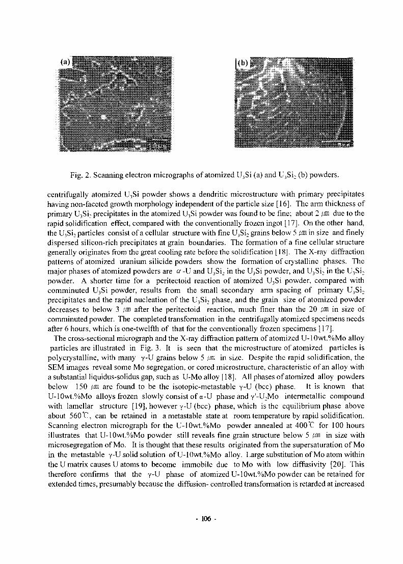
00
Fig. 2. Scanning electron micrographs of atomized U3Si (a) and U3Si2 (b) powders.
centrifugally atomized U3Si powder shows a dendritic microstructure with primary precipitateshaving non-faceted growth morphology independent of the particle size [16]. The arm thickness ofprimary U3Si2 precipitates in the atomized U3Si powder was found to be fine; about 2 /an due to therapid solidification effect, compared with the conventionally frozen ingot [17]. On the other hand,the U3Si2 particles consist of a cellular structure with fine U3Si2 grains below 5 /an in size and finelydispersed silicon-rich precipitates at grain boundaries. The formation of a fine cellular structuregenerally originates from the great cooling rate before the solidification [18]. The X-ray diffractionpatterns of atomized uranium silicide powders show the formation of crystalline phases. Themajor phases of atomized powders are a -U and U3Si2 in the U3Si powder, and U3Si2 in the U3Si2
powder. A shorter time for a peritectoid reaction of atomized U3Si powder, compared withcomminuted U3Si powder, results from the small secondary arm spacing of primary U3Si2
precipitates and the rapid nucleation of the U3Si2 phase, and the grain size of atomized powderdecreases to below 3 /an after the peritectoid reaction, much finer than the 20 /an in size ofcomminuted powder. The completed transformation in the centrifugally atomized specimens needsafter 6 hours, which is one-twelfth of that for the conventionally frozen specimens [17].
The cross-sectional micrograph and the X-ray diffraction pattern of atomized U-10wt.%Mo alloyparticles are illustrated in Fig. 3. It is seen that the microstructure of atomized particles is
polycrystalline, with many y-U grains below 5 /an in size. Despite the rapid solidification, theSEM images reveal some Mo segregation, or cored microstructure, characteristic of an alloy witha substantial liquidus-solidus gap, such as U-Mo alloy [18]. All phases of atomized alloy powdersbelow 150 /an are found to be the isotopic-metastable y-U (bcc) phase. It is known thatU-10wt.%Mo alloys frozen slowly consist of a-U phase and y'-U2Mo intermetallic compoundwith lamellar structure [19], however y-U (bcc) phase, which is the equilibrium phase aboveabout 560 °C, can be retained in ametastable state at room temperature by rapid solidification.Scanning electron micrograph for the U-10wt.%Mo powder annealed at 400 °C for 100 hoursillustrates that U-10wt.%Mo powder still reveals fine grain structure below 5 /an in size withmicrosegregation of Mo. It is thought that these results originated from the supersaturation of Moin the metastable y-U solid solution ofU-10wt.%Mo alloy. Large substitution of Mo atom withinthe U matrix causes U atoms to become immobile due to Mo with low diffusivity [20]. Thistherefore confirms that the y-U phase of atomized U-10wt.%Mo powder can be retained forextended times, presumably because the diffusion- controlled transformation is retarded at increased
- 106 -

Mo content.
40 60 80Diffraction Angle, 20
100
Fig. 3. The cross-sectional micrograph (a) and the X-ray diffraction pattern (b) ofatomized U-10wt.%Mo alloy particles.
Major Characteristics of Atomized Fuels
Fig. 4. The cross-sections of the U3Si fuel meat with comminuted particles (a)and atomized particles (b).
Comminuted U3Si fuel particles with a certain aspect ratio lie along the working direction duringforming, i. e., in the extrusion or rolling direction. Fig. 4-(a) shows a cross-section of the fuel meatwith comminuted particles in which the fuel particles are reoriented along the working directionof the fuel meat. In contrast, the atomized particles shall never have an aspect ratio since they arespherical. Regardless rolling or extruding, they have no chance of developing anisotropicorientation along the working direction during forming. Fig. 4-(b) shows the atomized particleswithout anisotropic orientation in the fuel meat in comparison with the comminuted particlesaligned in the working direction. The shape of the fuel particles greatly effects the fuel propertiesin relation with the orientation in the fuel meat. The direction of heat transfer in the fuel meat of
- 107 -

reactor operation is perpendicular to the plate, which means a heat is dissipated perpendicular to theworking orientation of the fuel particles in the meat with the comminuted powder. Fig. 5 shows thedifference in thermal conductivity between the fuel meats with comminuted powder and atomizedone. The meat with the atomized particles has about 23% higher thermal conductivity in theheat-transfer direction of reactor operation than the one with the comminuted particles does. Thesedata of conductivity, which show the great difference, say that thermal conductivity increases by asufficient amount using atomized powder.
120 -
— > • v — ~
61wt% U
8•o
- ••
„ i ..J
* — 1 -» r •"
3Si-AI
*
1 . 1 _ . .._._
1 ' 1 ' 1 '
• AtoAongitudinal• Com./Longltudlnal• Ato./Transverse• Com./Transverse
-
•
• '
0 100 200 300 100 500 600 700
Temperature(°C)
Fig. 5. Thermal conductivity of 61wt.%U3Si-Al fuel.
E 20
von"),*,—•— Con¥TSxi3ed SO %
- • - A t o m i z e d 5 0 %
Atomized 1 5 *
100 150 200
Time(hr)
Fig. 6. Volume changes of fuel meats as a function of annealing time at 500 °C.
The annealing time versus the dimension percent increases for the heat treatment of theAl-15vol.% U3Si2 and the Al-50vol.% U3Si2 fuel samples at 500°C are shown in Fig. 6. U3Si2 fuelsamples with the comminuted powder showed a larger volume increase compared with thoseprepared with the atomized powder after annealing at 500°C. As the aluminum reacts with the fuel,
- 108 -

the fuel's volume increases due to the difference between densities of the original particle andreaction product, and to the pores produced by the Kirkendall effect [21]. It is supposed that thesmaller surface area of atomized spherical powder compared to the irregular comminuted powderis also related to the reduction of volume change in terms of the diffusion-controlled process. Inaddition, comminuted fuel samples have a higher porosity than atomized fuel samples, as illustratedFig. 7. Lots of pores in the fuel samples are stabilized by trace impurity gases such as hydrogen,due to the formation of the intermediate phase without dissolution of the gases [22]. It is thoughtthat higher porosity contributes to reducing a restraint force on the swelling.
Dimensional changes in the samples are given in Table 1. The U-2wt.%Mo sample exhibits arather steep volume increase, reaching 26% after 2,000 hours. The volume of the U-10wt.%Mosample, on the other hand, remains the same, except for a temporary decrease after the 1,000 houranneal. The U-10wt.%Mo/alurninum dispersion, however, increased in volume by 31% after 215hours at 500°C, similar to the volume increase in the U3Si2/aluminum dispersion. The retardeddiffusion behavior is primarily due to the fact that U-10wt.%Mo is not liable to decompose from anas-atomized metastable y-phase (bcc) solid solution into the equilibrium oc-U and U2Mo two-phasestructure, still leaving some y-U phase, despite thermal annealing at 500 °C for 215 hours. Inaddition, the substitutional molybdenum supersaturated in the unreacted U-10wt.%Mo island along
00.1 0.2 0.3 0.4
Vol. FRACTION PARTICLES
Fig. 7. The void content of fuel cores in extruded dispersion coreswith comminuted and atomized U3Si2 particles.
the cell boundary inhibits the diffusion of aluminum atoms into the particle. Consequently, theatomized U-10wt.%Mo powder showed good y-U phase stability at elevated temperatures, and theU-10wt.%Mo fuel meat with the rapidly solidified powder displays superior thermal compatibility
- 109-

with aluminum compared to U3Si2 [Fig. 8],
(Unit %)
Time
(hr)
11
40
107
350
1000
2000
U-2wt.%Mo
A i
-0.15
-0.03
0
+0.19
+1.83
+4.28
A d
-0.17
-0.30
-0.23
+0.06
+0.39
+10.86
Alloy
A V
-0.49
-0.63
-0.46
+0.31
+2.61
+26.00
U-10wt.%Mo
A i
-0.09
A d
-0.18
-0.02 -0.06
-0.14 -0.05
-0.07
-1.04
-0.12
0
-1.52
-0.11
Alloy
A V
-0.45
-0.14
-0.24
-0.07
-4.08
-0.34
Table 1 Dimensional changes of Al-24vol.% U-Mo fuel meatsafter annealing at 400°C for various times.
(a)
Fig. 8. Backscattered electron images of atomized fuel meat after annealing at 500°Cfor 20 hours; (a) U3Si2, (b) U-10wt.%Mo.
In-pile Irradiation of Atomized U3Si Fuel in HANARO
The HANARO fuel which is U3Si dispersion fuel in Al matrix has only been supplied by AECLin Canada. This irradiation examination has aimed at identifying the in-reactor performance andthe integrity of both atomized and comminuted U3Si dispersion fuel for the localization of the
- 110 -

Fig. 9. The design draft of the irradiation LEU fuel rods.
reactor operation, optical inspection, and examination post irradiation, were established. Theirradiation fuel rods are the same as the standard HANARO fuel rods except that the fuel meatlength of irradiation rod is 20 cm (Fig. 9). The irradiation fuel assembly consisted of 3 atomizedfuel rods, 3 comminuted fuel rods, and 12 dummy fuel rods. The irradiation fuel rods werefabricted using LEU metal. The end plugs were inserted at both ends of fuel meats technically.The co-extrusion then put the cladding on the fuel rods. All fabrication steps followed the qualitycontrol system which was developed by referring to the CANDU fuel Q/A system. The fuel meathomogeneity was inspected using a gamma scanning method and the soundness of the welding partwas inspected using a real time radiography method. In addition, the defects of the cladding wereinspected using an eddy current detection method. Safety analysis of the irradiation fuel assemblywas performed using the MCNP4A code supposing the linear power to be 27.5 MW. The resultscalculated for all parts divided by the 5 cm interval showed that the maximum linear power was101.06 W/m. According to the results calculated using the DIFAIR code, the maximum centerlinetemperature on the linear power 120KW/mwas expected to be 267°C. Also, for the linearpower of 110 KW/m, the temperature was 262 °C. The expecting linear power of the irradiationfuel rod is lower than the supposing temperature used for calculation. Accordingly the centerlinetemperature of irradiation fuel rod would be lower than 262 °C. The temperature is lower than thebreakaway swelling temperature 350°C and much lower than the blistering temperature 640°C. hiaddition, the swelling was calculated to be about 9.3% at 95 at% burnup using the DIFAIR computercode. This swelling value is much lower than the HANARO requirement of 20%. Consequently,the irradiation fuel rods were evaluated to maintain a soundness and a safety. The quality assurancesystem was established by applying the Q/A system of CANDU fuel fabrication. The Q/Aassurance plan was worked out first of all. And then the other Q/A documents, specially, materialspecification, product specification, process specification, procurement manual, flowsheet, workordering sheet, test and inspection plan, quality inspection instruction, technical qualifyingreport, and drawings were prepared. The quality inspection technologies of the Gamma ScanningSystem, Real Time Radiography System, and Eddy Current System were developed. Theestablished Q/A system was applied to the fabrications of dummy fuels, hydraulic test fuels, andirradiation test fuels.
- Ill -

As mentioned above, two test fuel assemblies designated HFT Bl and HFT-B2, including bothatomized and comminuted U3Si dispersion fuel, are supposed to be charged in HANARO. The HFTB2 assembly, which will begin to irradiate in the end of 1997 as the first step, is going to examineto the integrity of developed U3Si fuels under the normal linear power condition of 30-108 KW/m.It is planned to be discharged from the reactor after fuel burnup of- 30% and -60%, respectively,in order to examine the in-reactor behavior and the appearance integrity with the naked eye. Thetarget fuel burnup at this HFT B2 assembly will be -60 at.%. After the HFT B2 assembly showssound in-reactor behaviors similar to that produced by the AECL in Canada, the next HFT Blassembly, which is going to irradiate from the middle of 1998 as the second step, will examine tothe integrity of developed U3Si fuels under the high linear power condition of 113 KW/m. The targetfuel burnup at this HFT Bl assembly will be -85 at.%. These irradiation tests for the HFT B2 andthe HFT Bl assemblies are expected to be finished by the end of 1998. Thereafter, the HTF B3assembly for the actual proofs of the developed fuels will begin to charge and irradiate so that thein-pile integrity of the U3Si fuels may be examined, and compared with that of the actual driver fuelfor HANARO.
Miniplate and Microplate Irradiation of Atomized Fuels with ANL
In order to examine the in-reactor performance of atomized LEU U3Si2 fuel miniplate in theHANARO, the miniplate fuel assembly has been in the progress of design and fabrication in co-operation with the ANL and the BWXT in United States. An miniplate irradiation test rig ofatomized U3Si2 fuel was already designed and preliminarily manufactured (Fig. 10). Thermalhydraulic and linear power calculations were performed by using the PLTEMP and the MCNP4Acomputer codes respectively. The results obtained from hydraulic test for the preliminarilymanufactured rig showed that the pressure drop was 327 kPa at flowrate 9 kg/sec and met theHANARO requirement. The vibration measurement revealed that vibration amplitude is very low.For the development of U3Si2 atomization technology, an atomization system was modified fromoutside-coil-type to inside-coil-type. The disk rotation motor was improved using electric pulsemotor. The crucible and nozzle material was changed from ceramic-coated graphite to ZrO2
ceramic. Hence, a higher temperature could be applied to U3Si2 atomization. As the result, theatomized LEU U3Si2 powder has successfully been prepared in spring this year. The U3Si2 powderyield below 125 IM in size was 94%, compared to the totally produced U3Si2 powder weight. Thecarbon contamination was about 580 ppm and the powder generally had a spherical shape with asmooth surface, and also showed a narrow size distribution with the median size of 51 jm The LEUatomized U3Si2 fuel powder will be shipped from the KAERI to the ANL, as soon as the containerarrives at KAERI. So to mention of the following plan, miniature test plates containing the atomizedfuel powder will be produced or otherwise procured in ANL. KAERI will assemble the irradiationbundle and install it in the test rig. The test plates will be irradiated in the HANARO, and then thepost-irradiation examinations of the test plates will be performed.
The U.S. RERTR program is currently attempting to develop dispersion fuels having densities inthe range of 8 to 9 g-U/cm3. To gain initial fuel performance data on a sample of such y-stabilizeduranium alloy dispersion fuels, a microplate irradiation experiment has been initiated in theAdvanced Test Reactor (ATR) located in Idaho [15]. This experiment is scoping in nature,attempting to gain performance data on the following ten (10) different uranium alloy dispersion
- 112 -

125 ±
70- " - 25 „
3O+1in
1.27 to.03
0.51+003
Fig. 10. An atomized U3Si2 miniplate irradiation test rig.
^ U ^ U " 9 N b - 3 Z r ' U"6Nb-4Zr, U-5Nb-3Zr, U-6Mo-lPt, U-6M0-and U-10Mo-0.05Sn. In addition, U-lOMo and U3Si2 samples prepared by the centrifugal
atomizauon method m KAERI are included in this test. All fuels* th'is L t are'in an a l u Z S mmatrix and aluminum claddmg. These fuel types are contained in two irradiation vehicles
S f v r d RERTR;2-Each of^iiTadiation vehicles conta-32 "^cropi^e -:Both irradiation vehicles contain all fuel; types except two; the U-4Mo and U-5Nb-3Zr fuel typestTsmall f r f ,RTR'2- ^ MS e m p l ° y e d » ^ t6St W6re febricated * P^e form.^ueto small size of the fuel plates, they are referred to as "microplates". The external dknensions of themic robes are 3.000-in. in lengm, 0.875-in. in width, and 0.05-in. thickness (76 n T x 22 n l x L3
n o w ' d ^ r ^ y i 6 l d > l 0 W 1 2 5 m k s i z e w a s 96%> ^ P a r e d to the totally produced U3Si2
powder weight The carbon contamination was low below 1,000 ppm and the powder generallyhad a spherical shape, and showed a narrow size distribution with the median size of 51 w Zf u ^ f o l H C t T t e C t l ° n , f A 1 - 2 5 v o L % U 3 S i
2 fi*l ™eat prepared with atomized powder exhibited? o C ^ d l S t ^ U t l O n ^ * f P ^ 1 6 8 ' sometimes with cracked particles (Fig. 12-(a)). The U-10wt.o/oMo powder yield below 125 w in size was 97%, compared to the totally produced U3Si2
powder weight. The carbon contamination was below 500 ppm and the powder had a sphericashape with a smooth surface and showed a narrow size distribution with the median size of 53 S
fxn^,tiCr°SS"Sf , ° f t 1 - 2 5 " 0 1 0 7 0 1 1 - 1 0 ^ 0 7 ^ 0 foel mea* P«*ared with the atomized powo^rexhibited a uniform distribution of the particles, none of which were cracked (Fig 12-(b)TConsequently, good quality of U3Si2, and U-10wt.%Mo fuel cores could be obtained By using thedeveloped atomization technology, microplates which were loaded in the ATR reactor have beenf ^ t h A ™ t , T successfully. Two irradiation test vehicles have been fabricated and inserted
vlhide R S T O ^ ° " ^ffl? ° f ?6Se eXperiments b e ^ ^ August 1997. The experimentalvehicle N2RTR-1 is scheduled to undergo two reactor cycles totaling 91 days of irradiation (38
j S ^ S f S S ^ t?ff"^ f r°m^ r e a C t° r f°U 0 W i n 8 a S h u"d o w n-heduledforNovember 30,1997. The peak fuel burnup at this time is expected to be -43 at.% the RERTR-2
Di ch^rtTf RFPTP1^^r CyClCS t O t a l r g 245 ^ ° f ilTadiatiOn ( 1 ° 8 effeCtive Ml P ° w e r days).Discharge of RERTR-2 is anticipated to occur following the reactor shut down in June of 1998 ata peak fuel burnup of-79 at.%. Of particular interest are the extent of reaction of the fuel and matrix
- 113-

Maximum Fuel Zone
Nominal Fuel Zone
Thickness: 1.2-1.3 mm
Fig. 11. The microplate.
(a)
Fig. 12. The cross-section of Al-25vol.% U3Si2 (a) and Al-25vol.% U-10wt.%Mo(b)fuel meat with the atomized powder.
phases and the fission gas retention/swelling characteristics of these fuel alloys.If in cooperation with ANL in U.S. the irradiation test of atomization fuel is performed and the
improvement of fuel performance is proven, the atomization process would disseminate world-wide and a considerable profit could be achieved through the technology export. In addition,uranium high loading fuel for high performance research reactors would be hopefully developedwith application of atomization process. This result would be contributed to the development ofadvanced nuclear material.
- 114 -

Foreign Supply of Atomized Powders
Atomized U3Si2 and U-10wt.%Mo powders for CERCA were already prepared last month andcurrently are being packed for shipment now. Depleted uranium lumps with no trace of fissionproducts or transuranian elements were used to fabricate the atomized powders. The U3Si2 and U-10wt.%Mo powders had about 20% of the powders below 45 [M against the powders below 125 (Min limited size. The chemical compositions of as-atomized powders in this preparation are shownin Table 2. The metallurgical phases of the powders had almost pure U3Si2 in the U3Si2 powder andY-U in the U-10wt.%Mo powder. In addition, the atomized U3Si2 powder for BWXT are beingprepared now.
Tabel 2 The chemical compositions of as-atomized powders for CERCA(Unit: wt.% in alloying element, ppm in impurity element).
U3Si2
U-lOMo
U
92.0
90.8
Si
7.78
-
Mo
-
9.7
Cd
<10
<10
Al
37
86
Cu
10
20
Li
<10
<10
B
<0.3
<0.5
C
400
120
Conclusion
In order to simplify the preparation process and improve the properties of the uranium alloyfuels, a rotating-disk centrifugal atomization technique has been applied to the production of thefuel powders of uranium-silicide and uranium-molybdenum alloys. Most of the nuisances in thefabrication process of uranium-silicide and uranium-molybdenum fuels could be eliminated byobtaining the powders directly from the molten alloys, which enhances the production economyand results in product powders with less impurities.
The characteristics, specially, morphology, size distribution, alloy phase and microstructure ofhigh-density U3Si, U3Si2, and U-10wt.%Mo alloy powders have been examined. The out-pileproperties, including the thermal compatibility between atomized particles and the aluminum matrixin U3Si, U3Si2, and U-10wt.%Mo fuel meats, have been studied. The particle size distribution ofatomized U3Si, U3Si2, and U-10wt.%Mo powders could be controlled by adjusting the atomizationparameters irrespective of alloy composition. The resulting particle shapes of most powders arenear perfectly spherical with relatively narrow distribution, giving no chance of anisotropicalignment of the particles along the working direction. Thermal conductivity of the atomized U3Sifuel core increases in the radial direction due to the isotropic distribution of particles in the fuelrod, compared with that of comminuted U3Si fuel core. Formability increases in the extrudedU3Si2 fuel rod using spherical powders, which improves the U-loading drastically.U-10wt.%Mo powder has a fine grain structure with an isotropic y-V phase. In addition,U-10wt.%Mo fuel meats, show a excellent thermal compatibility with the Al matrix and maintaina relatively good phase stability.
- 115-

Moreover, the RERTR (reduced enrichment for research and test reactors) program, which recentlybegin to develop very-high-density uranium alloy fuels, including U-Mo fuels, further requires thecentrifugal atomization process to overcome the contamination of impurities and the difficulties ofcomminution. A cooperation with ANL in U.S. was established to develop high-density fuels withapplication of atomization technology for RERTR since Decemberl996. The microplate andminiplate irradiation tests of atomized fuels have been performed with ANL. If these resultsdemonstrate the stability and improvement of in-reactor behaviors, nuclear fuel fabricationtechnology with centrifugal atomization could be most-promising to the production methods of very-high-uranium-loading fuels for RERTR, and the atomization technology would disseminate world-wide.
References
[1] J. L. Snelgrove, et. al., Pro. of 19th International Meeting on Reduced Enrichment forResearch and Test Reactors, Seoul, Korea, 1996.
[2] A. Travelli, Pro. of 19th International Meeting on Reduced Enrichment for Research andTest Reactors, Seoul, Korea, October 6-10, 1996.
[3] G. L. Copeland, G. L. Hofman, J. L. Snelgrove, ANL/RERTR/TM-9, (1986).[4] R. F. Domagala, T. C. Wiencek, H. R. Tresh, Nucl. Technology, 62 (1983) 353.[5] G. L. Hofman and J. Rest, ANL/RERTR/TM-18.[6] U.S. Nuclear Regulatory Commission: "Safety Evaluation Report Related to the Evaluation of
Low-Enriched Uranium Silicide-Aluminum Dispersion Fuel for Use in Non-Power Reactors,"U.S. Nuclear Regulatory Commission Report NUREG-1313 (July 1988).
[7] D. F. Sears, L. C. Berthiaume, L. N. Herbert, ANL/RERTR/TM-9, 1986.[8] C. K. Kim, K. H. Kim, C. T. Lee, I. H. Kuk, Pro. of 14th International Reduced
Enrichment for Research and Test Reactors, 1991.[9] T. Kato, K. Kusaka, Materials Transactions, JIM. 31 (1990) 362.
[10] T. Kato, K. Kusaka, H. Horata, and J. Ichikawa, Tetsuto-Hagane, 6 (1985) 719.[11] J. P. Durand and Y. Fanjas, Pro. of 16th International Meeting on Reduced Enrichment for
Research and Test Reactors, Oarai, Japan, October 4-7,1993.[12] J. P. Durand and P. Laudamy andK. Richter, Pro. of 17th International Meeting on Reduced
Enrichment for Research and Test Reactors, Williamsburg, Virginia, USA, September 18-23,1994.
[13] J. P. Durand, Y. Lavastre, M. Grasse, Pro. of 20th International Meeting on ReducedEnrichment for Research and Test Reactors (to be published), Jackson-Hole, Wyoming, USA,October 5-10,1994.
[14] C. L. Trybus, T. C. Wiencek, M. K. Meyer, D. J. McGam, and C. R. Clark, Pro. of 20thInternational Meeting on Reduced Enrichment for Research and Test Reactors (to bepublished), Jackson-Hole, Wyoming, USA, October 5-10, 1994.
[15] S. Hayes, C. L. Trybus, and M. K. Meyer, Proc. of 20th International Meeting on ReducedEnrichment for Research and Test Reactors (to be published), Jackson-Hole, Wyoming, USA,October 5-10, 1994.
[16] R. Mehrabian, Int. Metall. Rev., 27 (1982)184.[17] R. West, H. Fredrikson, J. Mater. Sci., 20 (1985) 1061.
- 116-

[18] R. R. Anantatmula, A. A. Johnson, R. S. Vatne, Pro. of the International Meeting of theInternational Metallographic Society, 217 (1975).
[19] Konobeevskin et al, Proc. of the Second International Conference on the Peaceful Usesof Atomic Energy, Geneva, Switzerland, 1958.
[20] K. H. Eckelmeyer, Microstructural Structure, Vol. 7, eds. McCall (Fallen, 1977).[21] J. Burke: The Kinetics of Phase Transformation in Metals (Pergamon Press, Oxford, 1965)
pp 184-195.[22] T. C. Wiencek, R. F. Domagala, H. R. Tresh, Nucl. Tech., 71 (1985) 608.
- 117 -

The Second Seminar on the New Fuel Technology Toward the 21* CenturyNovember 25 - 26, 1997, KAER1, Taejon, Korea
The Effect of Rare Earth Element Additions onMicrostructural Properties and Irradiation Behavior of an
Fe-Ni-Cr Alloy for LMFBR Application*
by Jin-Young Park, Fuel Technology Center, KNFC
* This paper was not available at the time of publication.
- 119

KR9700375
The 'z Seminar on the New Fuel Technology Toward the 21st Century,
November 25 - 26, 1997, KAER1, Taejon, Korea
Design Characteristics of Metallic Fuel Rod on Its In-LMR
Performance
Woan Hwang, Hee Young Kang, Cheol Nam, and Jong Oh Kim
Korea Atomic Energy Research Institute
P.O. Box 105, Yusong, TaeJon, Korea, 305-600
Abstract
Fuel design is a key feature to assure LMR safety goals. To date, a large effort had been
devoted to develop metallic fuels at ANL's experimental breeder reactor (EBR-II). The major
design and performance parameters investigated include; thermal conductivity and
temperature profile; smear density; axial plenum; FCMI and cladding deformation including
creep, and fission gas release. In order to evaluate the sensitivity of each parameter, in-LMR
performances of metallic fuels are not only reviewed by the experiment results in literatures,
but also key design characteristics according to the variation of metallic fuel rod design
parameters are analyzed by using the MAC SIS code which simulates in-reactor behaviors of
metal fuel rod. In this study, key design characteristics and the criteria which must be
considered to design metallic fuel rod in LMR, are proposed and discussed.
1. Introduction
In 1983, a concept emerged at Argonne National Laboratory (ANL), called the Integral
Fast Reactor concept (IFR), the objective of which was to offer a safe and economical
solution to the technical and institutional issues that had inhibited nuclear power from meeting
- 121 -

a larger share of the world's energy demands[l]. The IFR fuel cycle is based on pyro-
processing and injection-casting fabrication. The steps in this fuel cycle are few and all
processes are extraordinarily compact[2,3]. The technical feasibility of IFR had been
demonstrated and the technology database had been established to support its practicality
before IFR project was suspended in 1995 [4]. Also, metallic fuel properties had provided for
the significant breakthroughs achieved by 1994[5]. Metallic fuel appeared to be the most
suitable candidate for the integral concept, and the U-Pu-Zr metallic fuel system, which was
under development in the late 1960's, was chosen as the candidate fuel because of superior
performance characteristics over other metallic fuel systems. By the utilization of small
modular fast breeder reactor design concept, the LMFBR power plant with binary (U-Zr) and
ternary (U-Pu-Zr) uranium alloy fuel, pool-type reactor configuration, liquid sodium cooling
and integral fuel cycle based on pyrometallurogical processing and injection-cast fuel
fabrication, has inherent safety and high breeding ratio, and it is also expected to be more
economical. Therefore, renewed interest in metallic fuel for FBR has arisen in the USA, Japan,
China, and Korea. According to the KALIMER development program, KALIMER with
metallic fuel shall be built by the middle of 2010's. KALIMER is to be the first LMR in Korea
where a commercial LMR is expected to be operated in 2030's. The base alloy, binary (U-
10%Zr) metal fuel is a potential start-up for KALIMER as driver and blanket fuels[6,7]. As
mentioned before, metallic fuel properties had provided for the significant breakthroughs
achieved by 1994. The good neutron economy of metallic fuel provides for a good neutron
economy and effective breeding. This attribute may not appear significant today when energy
resources seem plentiful but it does provide a long-term solution if one is needed and no
additional development cost[8,9]. The immediate benefit of this property, however, enables
minimizing the burnup reactivity swing. This drastically reduces the required control worth
such that even with a multiple-rod-runout transient overpower initiator, the passive reactor
response limits temperature increase [9,10]. Another metallic fuel property, high thermal
conductivity, enables passive response to the loss-of-flow and loss-of-heat sink upset events.
Because of the high thermal conductivity, radial temperature gradients in the fuel rod are
small and heat stored in fuel slug is small compared to ceramic fuel pellet. In-LMR
performances of metallic fuels are reviewed in section 2, by the experiment results in
literatures. Also, a sensitivity study on the variation of design parameters for metallic fuel rod
is performed by using the MACSIS[7] code in section 3.
2. Irradiation Behavior of Metallic Fuel
Fuel performance issues important to design of advanced LMR systems include fission
gas release and swelling, fuel-cladding interaction, axial growth of the fuel and the breach
- 122 -

characteristics demonstrated by metallic fuels.
2.1 Swelling and Fission Gas Release
The general swelling behavior for U-Zr and U-Pu-Zr alloys is the increase of fuel pin size
versus burnup. Virtually all length increase takes place during a lower burnup interval before
the swelling fuel slug contacts the cladding. The leveling-off in axial swelling is thus
determined by the fuel-smeared density. The planar smeared density in typically chosen at
approximately 75 % to allow sufficient swelling, approximately 30 %, to facilitate fission gas
release from the fuel slug. This much planar swelling world, for isotropic swelling, translate
to a length increase of approximately 5 %[11]. However, the observed length increases are
consistently smaller, indicating anisotropic swelling. The main reason for this effect appears
to be the difference in swelling behavior between the hotter center of the fuel pin and the
colder periphery.
2.2 Fuel-cladding Interaction
Fuel-cladding interaction that may result in cladding failure can be both mechanical and
chemical.
2.2.1 FCMI (Fuel-Cladding Mechanical Interaction)
Since the presence of open (interconnected) fission gas porosity appears to be a key
feature in reducing FCMI, the question arises as to what the effect of accumulation of low-
density solid fission products on this porosity might be at high burnup. The following
discussion shows an approximate calculation of the next volume change due to non-gaseous
fission product accumulation. The accommodation of the non-soluble fission products
predictably results in a volume expansion as a function of burnup.
However, the U and Pu are depleted from the lattice as they fission, resulting in a volume
decrease that partially offsets the volume expansion due to fission products. Further, it can be
assumed that all the fission product Zr, Nb, and Mo are soluble in the matrix, which in turn
compensates for some of the volume decrease due to the disappearance of U and Pu from
fissioning. Thus, non-gaseous fission products contribute to the volume change in three
ways[ll]:
(1) Volume increase due to non-soluble fission products
(2) Volume decrease due to the fissioning U and Pu
(3) Volume increase due to the increase of the Zr, Mo, and Nb, which are soluble in fuel
matrix.
To date, the tests of IFR metallic fuel clad in U-Zr and U-Pu-Zr alloys have shown no
- 123-

definitive evidence for FCMI due to the low levels of total strain measured. Present element
design allows the fuel sufficient free swelling due to as-built smeared density of about
75 %[11]. Thus, the gas bubble pressure in fuel slug does not transmitted directly to the
cladding. The important point is that no unexpected large cladding strain, which would affect
pin reliability, has been observed in as-built smeared density (75-80%) fuel with HT-9 clad.
As built 75 % smeared density fuel rod allows free fuel swelling of approximately 30 %, at
which point porosity becomes largely interconnected and open to the outside of the fuel,
releasing a large fraction of the fission gas to a suitably large plenum at the top of the element.
2.2.2 Fuel-cladding Chemical Interaction(FCCI)
FCCI in an all-metallic fuel element is in essence a complex multi-component diffusion
problem. It involves the inter-diffusion of fuel and cladding constituents at operating
temperatures [12]. Specifically, the inter-diffusion has been characterized by diffusion of Fe
and Ni, when available as cladding constituents into the fuel with corresponding diffusion of
lanthanide fission products(La, Ce, Nd, Sm, Pr) into the cladding. The inter-diffusion is also
characterized by diffusion of cladding alloying elements into the body of the fuel slug. The
potential problem of inter-diffusion of fuel and cladding components in essentially two-fold:
weakening of cladding mechanical properties and formation of relatively low melting point
compositions in the fuel.
Experimental data[ll] on diffusion experiments with uranium also lead the researchers to
conclude that Ni played an important role in cladding fuel inter-diffusion. Their findings and
conclusions are relevant to the newly developed low-swelling cladding material used for the
IFR fuel elements, such as HT-9. In the case of basically Ni-free ferritic steel, HT-9, the U6Fe
and UFe2 type phases form a single zone without the finger-like structure. There exists a
eutectic composition between these two phases the temperature of which depends on the
concentration of Pu, Ni and Zr in the phases, as well as U and Fe. The eutectic temperature in
the Fe-U-Pu-Zr system drops significantly with Pu concentration, which may be explained the
lower melting temperatures for the 26 wt% Pu fuel. The melting in this case is also started in
the fuel side of diffusion couple[13]. At very high temperatures of 725-800 °C eutectic
melting occurs in a short time. The thickness, uniformity, and rate of formation of the Zr layer
appears to be the controlling factor. It seems that a thick and uniform Zr layer retards the
formation of molten phases, and that the ample availability of Zr, and N in particular, can
assure such a layer[13].
3. Parametric Study
3.1 Design tool
- 124 -

MACSIS code is used for present parametric study. MACSIS is metallic fuel performance
computer code, which calculates the thermal performance characteristics and dimensional
changes of the fuel rods in a fast neutron environment. MACSIS is comprised of a series of
subroutines, which model certain liquid metal reactor fuels phenomena. MACSIS code
calculates the temperature distribution, thermal expansion, axial growth, and gas release, and
the radial redistribution of the fuel alloying elements during irradiation in the metallic fuel
slug assuming that the fuel slug is an infinitely long rod concentric with an infinitely long
clad. This assumption, together with the assumption of axisymmetry, makes the analysis one-
dimensional. The other major assumption is that the conditions of the fuel and its environment
are at steady state once an element power is specified. A detailed thermo-mechanical analysis
is performed in the radial direction with provisions to specify up to 10 radial rings for the
fuel-cladding system. Axial variations in operating conditions are accounted for by inputting
powers and fast fluxes for up to 20 fuel axial nodes and one plenum node. Thermally, the
axial nodes are coupled through the calculated coolant temperatures. However, axial heat
conduction is ignored, and there are no provisions for mechanical coupling between axial
nodes, except for calculating rod internal pressure. The heat generated in each segment and
released fission gas is accumulated over the segments for calculation of coolant temperatures
and plenum pressure.
3.2 Temperature profile calculation
Axial temperature distributions for KALIMER fuel, cladding, and coolant are plotted in
Fig. 1 for fresh fuel. The inlet and outlet coolant temperatures of KALIMER are 360 °C and
530 °C, respectively. The outlet temperatures of fuel assemblies are maintained
homogeneously by orificing the flow rate through each assembly. Since axial power profile of
the pin has a chopped cosine shape, the coolant and cladding temperatures are S-shaped
curves and their shapes hardly change during the irradiation. The temperature difference
between coolant and cladding is small due to high heat removal rate of the sodium coolant.
The temperature drop across the fuel-cladding gap is also small because sodium with high
thermal conductivity is filled in the gap. Furthermore, the high thermal conductivity of the
metallic fuel slug gives very low thermal gradient in radial direction. Therefore overall
operating temperature of metallic fuel pin is very lowly maintained during normal operation
of the reactor, and it has a comparatively low stored energy. This facet implies that metallic
fuel gives a little thermal shock in the flow channel during RBCB (run beyond cladding
breach) operation. Because of high heat removal characteristic of metallic fuel pin, the peak
temperature of fuel centerline appears near to the top of the fuel pin. Should the accident
sequence proceed to fuel melting, the melting initiates at the top of fuel pin so that molten fuel
easily expand into plenum region, this provide a significant source of negative reactivity
feedback.
- 125-

ps1&
650
600-
550-
500-
450-
400-
350
9- fuel center
X - fuel surface
+— clad outer
coolant
axial power
1 r~0.0 0.1
—I—I—I—
0.4 0.5~T ' 1 ' 1 ' 1—
0.6 0.7 0.8 0.90.2 0.3
Normalized Axial Position of Fuel, x/L
1.1
1.0
0.9
0.8
0.7
0.6
2Q.
o
50.4 T3
0.3
0.2
0.1
0.01.0
(0
Fig. 1 Axial Temperature Distribution of KALIMER Fuel Pin at Beginning of Life
(peak linear heat = 330 W/cm)
Fig. 2 shows several cases of temperature variation with respect to linear heat generation
of a typical KALIMER fuel pin. In the design of metallic fuel pin, fuel temperature limits on
fuel melting and eutectic/liquid-phase formation should be considered in the temperature
point of view. Based on the aggregate of TREAT tests, ANL concluded that centerline fuel
melting, even extensive melting exceeding 80 % of a given radial cross-section, is not a
problem and does not result in pin failures[14]. However, the prevention of centerline fuel
melting is regarded as a design limit of KALIMER fuel pin for conservatism. The solidus
temperature of U-lOZr metallic fuel is known as 1240 °C so that the linear power-to-melt for
BOL (beginning of life) is around 1240 W/cm by the calculation of MACSIS code. As
irradiation proceeds, the thermal conductivity of metallic fuel is degraded down to
approximately 50 % of initial condition at around 1.5 at.% burnup. For the further irradiation,
the conductivity is restored with bond sodium infiltration into fuel slug. In the case of 50 %
- 126 -

degraded thermal conductivity, which is the worst condition of fuel temperature, the
calculated power-to-melt is about 970 W/cm. These levels of power-to-melt are very high
compared to those of mixed oxide fuel, and this means metallic fuel has a large safety margin
in the reactivity related accidents such as UTOP (unprotected transient overpower).
1300
oo
I2
I
1200-
1100-
1000-
900-
800-
700-
600
500
- 0 - fuel center at k=0.5k0
- O - fuel center at BOL
—)— clad inner surface
—*— clad at hot channel
300 400 500 600 700 800 900 1000 1100 1200 1300
Linear Power, W/cm
Fig. 2 The Operating Limits on Linear Power Rate for Metallic Fuel Pin in KALIMER.
During irradiation, complicated multi-element metal mixture including fission product is
formed at the fuel-cladding interface of a metallic fuel pin. According to the experimental
results, no liquid phase has been observed at temperature below 700 °C. Above this
temperature, liquid phase is formed at the interface and its penetration reduces cladding
thickness. Although the detail mechanism of this behavior is not known yet, it is being
revealed that the penetration does not cause an instantaneous failure but proceeds at a certain
rate that depends on the composition and temperature of the mixture. Considering this
indication, the most conservative criterion that prevents any eutectic reaction during steady
- 127-

state operation is considering in KALIMER fuel pin design. Using the nominal irradiation
temperature of KALIMER fuel pin, the calculated power-to-eutectic is about 600 W/cm. If we
consider the hot channel temperature of 150MWe KALIMER core, the coolant temperature at
top-end of the fuel including +2CT uncertainty reaches 593 °C. In this case, the power-to-
eutectic is decreases to about 420 W/cm. The linear power of KALIMER fuel pin is not
determined yet, but the limiting pin power including overpower rate will be around 420 W/cm
based on above analysis.
3.3 FGR and rod internal gas pressure
The cladding strain of fuel pin with the high-smeared density is primarily creep strain due
to FCMI. The cladding strain of the low-smeared density can be accounted for by the plenum
pressure stress alone, which confirms[ll] that FCMI is virtually nonexistent in suitably
designed metallic fuel rods and that cladding stress is determined by the fission gas pressure
in the interconnected porosity.
5.0
ScS5
55E©
.2Q
CO0
Q .
4.5-
4.0-
3.5-
3.0-
2.5-
2.0-
1.5-
1.0-
0.5-
0.0
- X - FGP(EPL=0.9FL)
-*-FGP(EPL=1.1FL)
-+-FGP(EPL=1.3FL)
- m - strain(EPL=0.9FL)
-•-strain(EPL=1.1FL)
-A-strain(EPL=1 3FL)
1800
-1600
-1400
-1200
-1000
-800
6 8 10 12
Burnup, at.%
14 16 18 20
CO
-600 S
-400
-200
Fig. 3 The Evolution of Total Strain and Rod Internal Gas Pressure with Burnup According to
the Variation of Different Plenum Sizes
- 128 -

The effects on total diametric strain and rod internal gas pressure with different plenum
sizes were analyzed by MACSIS code. Fig. 3 shows that the evolution of total strain and rod
internal gas pressure with burnup according to the variation of different plenum sizes, under
very high operation condition with peak clad mid-wall temperature of 653 °C. As shown in
Fig. 3, the deformations at below range of 14 at.% burnup are less than approximately 0.5 %
in every cases. Apparently little diametric strain has occurred in case of 1.3 times plenum as
the length of fuel core, which shows that the deformations at below range of 18 at.% burnup
are only approximately 1 % or less. Less plenum length gives larger total diametric strain and
rod internal gas pressure. However, in case of 0.9 times plenum as the length of fuel core,
total diametric strain was largely increased up to 4.5 % at 18.1 at.% burnup.
3.4 Smear density and cladding strain
The effects on total diametric strain with different smeared-densities were analyzed by
MACSIS code, to evaluate the effective smeared-density value at which significant FCMI
does occur. Because the five types of different smeared densities differ mainly in the clad
strains behaviors. Fig. 4 shows that the evolution of total strain with burnup for different
smeared densities, under very high operation condition with peak clad mid-wall temperature
of 659 °C. Peak fuel surface and clad-inside temperatures were 668 and 667 °C, respectively.
Total diametric strain is generally increased as the smeared density increases.
Apparently little FCMI has occurred in both cases of 72 % and 76 % smeared-densities,
which shows that the deformations at below range of 18 at.% burnup are only approximately
1.7 % or less. This means no FCMI is occurred in the fuel pin with high-smeared density.
Maximum total diametric strain in case of 80 % smeared-density is approximately 3 %, the
level of this strain is acceptable by a narrow margin. However, in cases of 84 % and 88 %
smeared-densities, total diametric strains were largely increased up to approximately 5 % at
9.8 at.% at the burnup of 17.5 at.%, respectively. It may conclude that total diametric strains
are largely increased when the smeared densities are over than 80 %.
Below 550 °C of cladding temperature at normal operating conditions, it appeared that
there were no big differences of total diametric strain with burnup for different smeared
densities for which were analyzed in this study. In all cases of these, the integrity criteria of
clad are largely satisfied.
- 129-

oQ<
c
s55I0)
nj<u
10-
9 -
8 -
7 -
6 -
5 -
3 -
2 -
1 -
0 -
i • i * i • i
- • - - S.D. 72 %
- • • - S.D. 76 %
- A - S.D. 80 %
- T - - S.D. 84 %-•••- S.D. 88 %
•
-
f/ ;//L -
8 10 12
Peak Bumup, at.%
14 16 18 20
Fig. 4 Evolution of Total AD/D with Burnup for Different Smeared Densities
4. Conclusion
Key performance issues important to the design of metallic fuel system for advanced
LMR include fission gas release and swelling, fuel-cladding interaction, axial growth of the
fuel and the breach characteristics demonstrated by metallic fuels. It is appeared that metallic
fuel gives a little thermal shock in the flow channel during RBCB operation.
Parametric study is performed using the MACSIS code. For the worst case of 50 %
degraded thermal conductivity, calculated power-to-melt is about 970 W/cm, which is very
high comparing with that of MOX fuel. Considering the hot channel temperature of
KALIMER core, the power-to-eutectic is decreased to about 420 W/cm. Less plenum length
gives larger total diametric strain and rod internal gas pressure. However, in case of 0.9 times
- 130-

plenum as the length of fuel core, total diametric strain was largely increased up to 4.5 % at
18.1 at.% burnup. Apparently little FCMI has occurred in both cases of 72 % and 76 %
smeared-densities, which shows that the deformations at below range of 18 at.% burnup are
only approximately 1.7 % or less. It appeared that total diametric strains are largely increased
when the smeared densities are over than 80 %. Below 550 °C of cladding temperature at
normal operating conditions, it appeared that there were no big differences of total diametric
strain with burnup for different smeared densities so that the integrity criteria of clad are
largely satisfied.
References
1. Y. I. Chang, "The Integral Fast Reactor", Nuclear Technology, 88,129, November 1989.
2. C. E. Till and Y. I. Chang, "Progress and Status of the Integral Fast Reactor (IFR) Fuel
Cycle Development", Intl. Conf. on Fast Reactors and Related Fuel Cycles(FR'91),
Kyoto, Japan, October 28-November 1, 1991.
3. Y. I. Chang and C. E. Till, "Economic Prospects of the Integral Fast Reactor (IFR) Fuel
Cycle", ANL/CP-72603.
4. Y. I. Chang, "Status of Progress in IFR Development", Presented at the ASME Joint
International Power Generation Conference, 94-JPG-NE-14, Phoenix, Az, October 2-6,
1994.
5. Private Communication with Y. I. Chang (ANL).
6. Chang K. Park, "Status of Liquid Metal Reactor Development Activities in Korea: An
introduction to KALIMER", KAERI, November 1996.
7. Woan Hwang, Cheol Nam, Jeong Sik Yim, Young Cheol Kim, and Cho-Mann,
"Development status of MACSIS Code for Simulating the In-Reactor Behavior of
Metallic Fuel", Proceedings of the ASME/SFEN/JSME 5th International Conference on
Nuclear Engineering, May 26-30, Nice France 1997.
8. C. E. Till, "Fast Reactor Directions: The LMR Integral Fast Reactor Program at
Argonne," Proceedings of the 1990 International Fast Reactor Safety Meeting, IV-449,
Snowbird, Utah, August 12-16, 1990.
9. B.R. Seidel, G.L.Batte, N.E. Dodds, G.L. Hofman, et. al., " A Decade of Advances in
Metallic Fuel", ANS 1990 Winter Meeting, Washington D.C., Nov. 11-15,1990.
10. D.R. Pedersen and B.R. Seidel, "The Safety Basis of the Integral Fast Reactor Program",
Journal of Nuclear Safety, in press.
11. G.L. Hofman and L. C. Walters, "Metallic Fast Reactor Fuels", Nuclear Materials, Parti,
Vol. 10A, Published VCH Verlagsgesellschaft mbH.
- 131 -

12. G. L. Hofman, L. C. Walters and T. H. Bauer, "Metallic Fast Reactor Fuels", Progress in
Nuclear Energy, Vol. 31, No 112, 1997.
J13.G. L. Hofman, A. G. Hins, D. L. Porter, L. Leibowitz, and E. L. Wood, "Chemical
interaction of Metallic Fuel with Austenitic and Ferritic Stainless Steel cladding".
Proceedings of ANS International Conference on Reliable Fuels for Liquid Metal
Reactors, 4-121, Tucson, Arizona, September 7-11, 1986.
14. T. H. Bemer, et al., "Behavior of Metallic Fuel in TREAT Transient Overpower Tests",
ANS Topical Meeting on Safety of Next Generation Power Reactors, Seattle, WA, 1988.
- 132 -

KR9700376
The 2nd Seminar on the New Fuel Technology Toward the 21st Century,
November 25 - 26, 1997, KAER1, Taejon, Korea
Development of KALIMER Fuel Materials.
Chong-Tak Lee, Yeong-Seok Yang, and Young-Ho Kang
Korea Atomic Energy Research Institute,P.O. BOX 105 Yusung, Taejon 305-600, Korea
Abstract
The microstructure and precipitates of the U-10wt.%Zr alloy, one of the fuelcandidates for the liquid metal reactor, were studied. The matrix of the alloy wascomposed of an eutectoid lamellar structure and the precipitates were a Zr-rich phaseand SiZr phase. Atomized U-lOZr alloy powders showed fine dendrite structures andare considered to have a better resistance to swelling after irradiation and also, betterfission gas release properties due to more grain boundary areas. Ternary alloys, partof the Zr in U-lOZr alloy is substituted with other elements (e.g. Mo, Nb, Ta, W),showed fine lamellar structures. Ta and W added to ternary alloys have an especiallygood structural stability after heat treatment at 500 °C for 2000hrs.
1. Introduction
Since metallic fuels were developed for liquid metal reactors it had been consideredas not better than ceramic ones because it had been difficult to raise the burn-up dueto dimensional instability, swelling and interaction with cladding materials[l]. Howeverthe Argonne National Laboratory succeeded in developing a porous U-Zr metallic fuelwith raised burn-up for EBR-II and Mark III[2,3]. The fission gas products as volatilefission gas were released to the fuel element plenum space because fission gasbubbles interconnect each other to the fuel surface. Therefore the metallic fuel showedlow swelling, and good compatibility with the cladding material. Since metallic fuelhas higher density and greater thermal conductivity than ceramic fuels it could bepossible to adopt new concepts like compact core due to high linear power; a longburn-up life and blanketless core due to high proliferation; low decontaminationcoefficient of fission products and potential of Waste Burner, and so on.
Because the U-10wt.%Zr (unless otherwise stated, all compositions are in weightpercent) alloy is beneficial to fast fission gas release and has good compatibility withcladding material, it is used as the driver fuel and blanket.
In this study, the U-lOZr alloy was prepared by vacuum induction melting, and its
- 133 -

microstructure and precipitates were investigated. To develop a new metallic fuel alloywith reduced grain boundary cavitation swelling, faster fission gas release rate, highburn-up, and long life cycle, U-lOZr alloy powder was fabricated by centrifugalafomization. The microstructure of atomized powder was compared with that of thealloy ingot. Ternary alloys were also fabricated by substitution of third elements (e.g.Mo, Nb, Ta, W) was added and the microstructural change and structural stability athigh temperature were also investigated.
2. Experimental Procedure
The U-lOZr alloy was prepared by vacuum induction melting of depleted uraniummetal and a zirconium sponge (99.2%) at around 1600°C A Cylinder type graphitemold(025 x 250L) coated succesively with Y2O3 stabilized ZrO2, Y2O3 slurry and ZrCh•SiCh slurry was used for the 025 ingot cast and a quartz tube coated with the sameas above was used for the U-lOZr pin(01O, 06 each) cast. U-lOZr alloy powder wasprepared by atomizing the molten alloy on a graphite disc rotating at 22,000 rpm andthen cooling it with Ar gas.
U-Zr-X ternary alloys were prepared by vacuum melting the mixture of uraniummetal, zirconium sponge, and a third element(Mo, Nb, Ta, W) in a MgO crucible andthen furnace cooling. After holding the ternary alloy specimens at 500 °C for 2000hrs,the microstructural change was investigated by a scanning electron microscope. Themicrostructure of the metallic fuel specimen was observed by SEM, and TEM,Identification of the alloy phase and precipitates was done by XRD and EDS.
3. Results and Discussion
3.1 The Microstructure of U-lOZr Alloy.
A sound ingot of the U-lOZr alloy was prepared by vacuum induction melting andcasting in a graphite mold. Table 1 shows the chemical composition of the top,middle and bottom section of the ingot. The Zr content shows about a 9 wt.%, i.e. a
Table 1. Chemical composition of U-lOZr alloy Ingot.
Top
Middle
Bottom
Uranium
Bal.
Bal.
Bal.
Zr(wt.%)
9.05
8.95
9.10
C(ppm)
63
26
68
O(ppm)
899
789
913
N(ppm)
26
23
28
Mg(ppm)
< 20
< 20
< 20
Si(ppm)
<100
<100
<100
- 134 -

the yield of 90%. Segregation of the Zr element with an ingot position was ±0.076wt.%.
When slow cooling of the U-5Zr alloy, the solid solution of the U-Zr decomposesinto a lamellar structure of a uranium and a 8 phase. Fig. 1 is an SEM micrographof the U-lOZr alloy. It also shows a wel-developed lamellar structure that is knowngood structure to fission gas release in LMR. The thickness of the lamellar structureis 0.2-0.3//m. Fig. 2 shows an SEM micrograph of precipitates in the U-lOZr alloy.Precipitates show three different shapes - a round, rectangular and rod shape. Fig. 3-a)shows an elemental mapping of U, Zr and Si of the round, rectangular and rodshaped precipitates. Round-shaped precipitate is revealed to be the Zr-rich phase withmore than 94wt.%Zr, and the rod-shaped precipitate is composed of Zr and Si. Fig.3-b) shows an elemental mapping of U, Zr and Si of the rectangula-shapedprecipitate. The rectangula-shaped precipitate is also composed of Zr and Si. Fig. 4-a),b), c) are TEM bright field images of the lamellar matrix and precipitate of theU-lOZr alloy. The matrix shows a wel-developed lamellar structure and the dark phaseis revealed to be 97-99 at.%U, a phase, and the bright phase to be a 8phase(UZr2) with 55-67 at.%Zr. The round-shaped precipitate is a Zr-rich phase withabove 94 at.%Zr. The rod-shaped precipitate seems to be SiZr2 with about 66 at.%Siand about 34 at.%Zr. Fig. 5 shows an X-ray diffraction pattern of the U-lOZr alloy.X-ray peaks reveal a uranium, 8 (UZr2) phase and a Zr-rich precipitate.
3.2 Pre-pin Casting
A U-lOZr pre-pin(06.6x480L) with a clean surface was fabricated by gravitycasting instead of vacuum injection casting. The pouring temperature was 1600°C, andthe top of the graphite mold was preheated to above 500 °C. Fig. 6 is a photographof the pre-pin casting. Fig. 7-a), b) are SEM micrographs of the top and the bottompart of the pre-pin. The top part shows a well-developed lamellar structure while thebottom part shows a fine structure, but not a fully-developed lamellar structure. Thisis attributed to the difference in the cooling rate between the top and bottom portionof the graphite mold. Since the top part of the mold is hotter than the bottom partdue to the heat of the crucible, the cooling rate of the melt in the bottom part ishigher than the later-poured melt in the top part and the nucleation rate within themelt in the bottom could be much higher, Accordingly, atomic diffusion was morerestricted in the bottom portion and therefore, a finer lamellar structure developed inthe bottom part.
3.3 Atomized U-lOZr Alloy Powder
The chemical composition of the atomized powder is shown in Table 2. Thezirconium and carbon contents in fine powders were usually lower than those in
- 135-

<'<;'•••A/41 -:- •"."-• • > /
Fig. 1 SEM image of U-lOZr alloy ingot.
Fig. 2 SEM image of the precipitates in U-lOZr alloy ingot.
- 136 -

a) Round shaped precipitate
Label: L2-U-ZR (5 Sep 97 14:51:08)
b) Rectangular shaped precipitate
Label M7-U-ZT (5 Scp »7 1639:48)
Fig. 3 X-ray (U, Zr, Si, O) mappings of the precipitate in U-lOZr alloy.
- 137 -

a) Lamellar matrix
b) Round shaped precipitate c) Rod shaped precipitate
*S£& 'M^ • S*° 's '^1 ̂ s \ A i ;
Fig. 4 TEM BF images of the lamellar matrix and precipitates in U-lOZr alloy.
- 138 -

. IK
30.00 100.00 120.00
Fig. 5 X-ray diffraction pattern of U-lOZr alloy revealing
the presence of 8 -UZr2 in a uranium.
Fig. 6 Photograph of U-lOZr pre-pin by gravity casting into graphite mold.
- 139 -

a) Top
b) Bottom
Fig. 7 SEM image of a) top and b) bottom portion U-lOZr pre-pin.
- 140 -

50 100 200Particle Size (
400 700
Fig. 8 Particle size distribution of atomized U-lOZr powders.
Table 2. Chemical composition of U-10wt.%Zr atomized powder.
Powder
63 ~
106 ~
180 ~
size(//m)
75
125
212
Uranium
Bal.
Bal.
Bal.
Zr(wt.%)
7.1
8.1
8.1
C(ppm)
100
110
180
O(ppm)
610
610
610
N(ppm)
10
10
10
Mg(ppm)
< 30
< 30
< 30
Si(ppm)
<100
<100
<100
- 141 -

a) 53//m max. b) 53 -
c) 90 - 106/an d) 150 -
e) 250 - 3
Fig. 9 A series of SEM image of atomized powder shape
with different powder size range.
- 142 -

coarse ones. Fig. 8 shows the size distribution of atomized U-lOZr powders. Atomizedpowder larger than 300#m was about 30wt.%. Fig. 9-a), b), c), d), e) are SEMmicrographs of atomized U-lOZr powders. Powders below 100//m in diameter weremostly spherical shape and coarse powders as large as 300//m in diameter hadsubangular shapes with rough surface. This attributed to the lower melt temperatureand instantaneous solidification of the melt droplet upon reaching the rotating disc.
Fig. 10 shows an SEM micrograph of atomized powder which shows a finedendrite structure with an arm spacing of 2-4fm. It is expected that this fine structurewith random texture is advantageous to the reduction of grain boundary cavitationalswelling due to the random distribution of anisotropic irradiation growth of uraniumgrains. Also, the fine structure can raise the grain boundary area and enhance fissiongas release during irradiation, thereby reducing the swelling.
Fig. 11 shows the density variation of atomized powders with particle size. Thedensity tends to increase with powder size, but only to a small extent. Fig. 12 showsan X-ray diffraction pattern of atomized U-lOZr powders. The intensity peaks fromthe atomized powder are smaller in peak numbers compared with those from theingot, and less sharp. The matrix of atomized powders is a mixture composed of ana uranium phase and a 8 (UZr2) phase and the precipitate is a Zr-rich phase, similar
to those of the U-lOZr ingot.
3.4 Development of U-7Zr-3X(X=Mo, Nb, Ta, W) Alloy
To achieve a finer lamellar structure and to develop a higher burn-up metallic fuelmaterial, third elements of 3wt. % (Mo, Nb, Ta, W respectively) were substituted forZr in the U-lOZr alloy. Fig. 13-a), b), c), d), e) are SEM micrographs of U-lOZr andU-7Zr-3X(X=Mo, Nb, Ta, W) ternary alloys. All ternary alloys show a clear lamellarstructure compared with the U-Zr binary one. The X-ray diffraction study revealed analloy phase, like U2M0, Mo2Zr, W2Zr with an a uranium and 8 (UZr2) phase internary alloys. Fig. 14-a), b), c), d), e) show SEM micrographs of binary and ternaryalloys after holding at 500"C for 2000hrs. The U-lOZr binary alloy shows that thelamellar structure is decomposed to some extent and finally into a porous structure.The ternary alloys, U-7Zr-3Mo and U-7Zr-3Nb, showed a partly decomposed lamellarstructure, while the U-7Zr-3Ta and U-7Zr-3W alloys showed good thermal stability,i.e. a clear lamellar structure with the same lamellar thickness, even after the heattreatment.
4. Summary
To develop a metallic fuel material for an LMR, a U-lOZr ingot and powder wereprepared by vacuum induction melting and atomizing, respectively. Phases wereidentified by XRD and EDS analyses. Ternary alloys, third elements (Mo, Nb, Ta, W)
- 143 -

substituted for Zr, were also fabricated and the thermal stability of the microstructurewas studied after heat treatment at 500 °C for 2000hrs.
1. The U-lOZr alloy is composed of a lamellar eutectoid structure with an auranium and 8 (UZr2) phase. A round-shaped Zr-rich phase, rod-shaped SiZr;phase and rectangular-shaped SiZr phase were observed.
2. A U-lOZr pre-pin (06.6X48OL) was successfully fabricated by gravity castingwith relevant melt temperature and preheating of the mold.
3. Atomized U-lOZr alloy powder showed a fine dendrite structure with randomorientation due to rapid solidification. It is expected that atomized powders shallshow reduced grain boundary cavitation swelling and enhanced fission gasrelease rate due to the larger grain boundary areas.
4. Ternary alloys, third element(Mo, Nb, Ta, W) substituted for Zr, showed a clearlamellar structure. Ta or W added ternary alloys showed good thermal stabilityof the microstructure compared to the binary one at 500 °C for 2000hrs, whileMo or Nb added ternary alloys showed similar structural instability at the sameheat treatment condition as the binary U-lOZr one.
Reference
1. J. H. Kittel et al., J. Nucl. Mater., 204, pp. 1-13, 1993.
2. R. G. Pahl et al., Metallurgical Transaction A, 21 A, pp.1863, 1990.
3. R. D. Leggett and L. C. Walters, J. Nucl. Mater., 204, pp23-32, 1993.
Fig. 10 SEM images of cross-section of atomized U-lOZr powder.
- 144 -

20.0
19.0
18.0
i 16.0
l-^15.0
r E 1 4 0
o
to12.0
11.0
10.0100 200. 400
Particle Size (//m)
Fig. 11 Variation of the density of atomized U-lOZr powder with particle size.
.IK
CDQ_
CJ .05
20.00 40.00 60.00 80.00 100.00 120.00
Fig. 12 X-ray diffraction pattern of atomized U-lOZr powder.
- 145-

a) U-lOZr b) U-7Zr-3Vlo
'' 'si ( A '»',">.''" t
; y .1.fkMt \
c) U-7Zr-3Nb d) U-7Zr-3Ta
e) U-7Zr-3W
Fig. 13 SEM images of binary U-lOZr and ternary
U-7Zr-3X(=Mo, Nb, Ta, W) system.
- 146 -

a) U-lOZr b) U-7Zr-3Mo
c) U-7Zr-3Nb d) U-7Zr-3Ta
e) U-7Zr-3W
Fig. 14 SEM images of U-7Zr-3X(=Mo, Nb, Ta, W) ternary
system after heat treatment at 723K for 2000hrs.
- 147 -
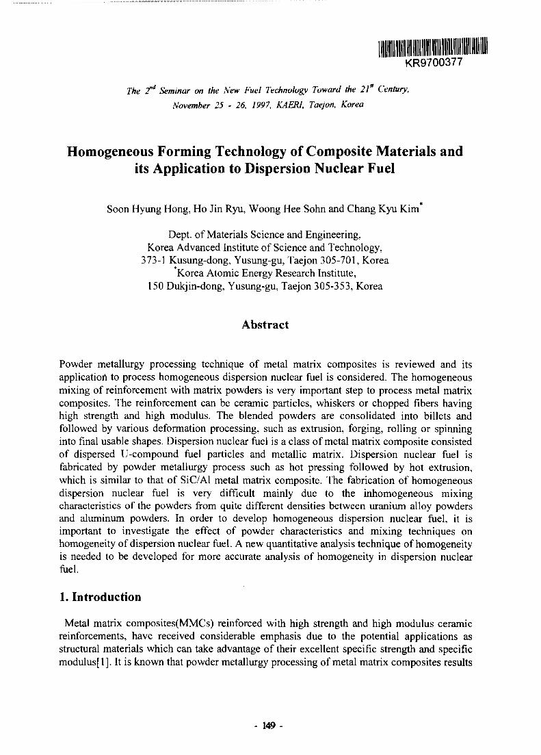
KR9700377
The 2nd Seminar on the New Fuel Technology Toward the 21st Century,
November 25 - 26, 1997, KAERI, Taejon, Korea
Homogeneous Forming Technology of Composite Materials andits Application to Dispersion Nuclear Fuel
Soon Hyung Hong, Ho Jin Ryu, Woong Hee Sohn and Chang Kyu Kim*
Dept. of Materials Science and Engineering,Korea Advanced Institute of Science and Technology,
373-1 Kusung-dong, Yusung-gu, Taejon 305-701, KoreaKorea Atomic Energy Research Institute,
150 Dukjin-dong, Yusung-gu, Taejon 305-353, Korea
Abstract
Powder metallurgy processing technique of metal matrix composites is reviewed and itsapplication to process homogeneous dispersion nuclear fuel is considered. The homogeneousmixing of reinforcement with matrix powders is very important step to process metal matrixcomposites. The reinforcement can be ceramic particles, whiskers or chopped fibers havinghigh strength and high modulus. The blended powders are consolidated into billets andfollowed by various deformation processing, such as extrusion, forging, rolling or spinninginto final usable shapes. Dispersion nuclear fuel is a class of metal matrix composite consistedof dispersed U-compound fuel particles and metallic matrix. Dispersion nuclear fuel isfabricated by powder metallurgy process such as hot pressing followed by hot extrusion,which is similar to that of SiC/Al metal matrix composite. The fabrication of homogeneousdispersion nuclear fuel is very difficult mainly due to the inhomogeneous mixingcharacteristics of the powders from quite different densities between uranium alloy powdersand aluminum powders. In order to develop homogeneous dispersion nuclear fuel, it isimportant to investigate the effect of powder characteristics and mixing techniques onhomogeneity of dispersion nuclear fuel. A new quantitative analysis technique of homogeneityis needed to be developed for more accurate analysis of homogeneity in dispersion nuclearfuel.
1. Introduction
Metal matrix composites(MMCs) reinforced with high strength and high modulus ceramicreinforcements, have received considerable emphasis due to the potential applications asstructural materials which can take advantage of their excellent specific strength and specificmodulus[l]. It is known that powder metallurgy processing of metal matrix composites results
- 149-

in better mechanical properties with homogeneous microstructure compared to castingprocess[2-3]. The powder metallurgy process of metal matrix composites consists of mixing,consolidation and secondary processing and the process parameters at each stage need to becontrolled to improve the homogenization and densification of metal matrix composites[4].
Mixing of powders is defined as the thorough blending of reinforcements and matrix alloypowders into same nominal composition with the uniform distribution of reinforcements[5]. Abillet is formed by either hot pressing in vacuum or hot isostatic pressing. The microstructuresof composites are sensitively determined by the consolidation conditions and are also closelyrelated to the mechanical properties[6]. Secondary processing such as extrusion, rolling,forging and superplastic forming is also an important fabrication step of metal matrixcomposites. Specifically, in order to achieve maximum composite strengthening effect by theaddition of whiskers, the whiskers need to be aligned parallel to one direction[7]. The hotextrusion process is the most common deformation process applied to align the whiskers inmetal matrix composites[8-9].
Dispersion nuclear fuels consisted of U-compound fuel particles dispersed in metallic matrixare distinguished from the metallic uranium fuel used in early reactors and the U02(ceramicpellet) fuel used in most power reactors today[10-l 1]. The basic idea of a dispersion fuel is tofabricate by powder metallurgy process such as hot extrusion or hot rolling, which is similarto that of SiC/Al metal matrix composite[ll]. In order to get high performance dispersionnuclear fuel, the uranium alloys powder need to be homogeneously distributed in a aluminummatrix. However, the fabrication of homogeneous dispersion nuclear fuel is very difficultmainly due to the inhomogeneous mixing characteristics of the powders from quite differentdensities between uranium alloy powders and aluminum powders.
In this paper, the fabrication processes of composite materials and dispersion nuclear fuelsare compared. The improvement on homogeneity of dispersed uranium fuel particles inaluminum matrix is investigated to develop a high density fuel with improved characteristicssuch as homogeneity, fabricability, compatibility with aluminum, and stable irradiationbehavior.
2. Fabrication Process of Metal Matrix Composites
The conventional fabrication process of metal matrix composites includes mixing ofreinforcement with matrix powders, consolidation of blended powders and secondaryprocessing of consolidated billet. Fig. 1 shows the conventional processing routes of SiC/Almetal matrix composite via powder metallurgy process.
2-1. Mixing of Reinforcements with Matrix Powders
A mixing step normally follows the selection of the reinforcement and matrix of compositematerials. The mixing step ultimately controls the final properties of metal matrix composites,which are intended to achieve[12]. The properties of consolidated composite materials aresensitively dependent upon the homogeneity of the mixture. Generally, dry mixing, wetmixing and ball milling are used for mixing of metal matrix composites. Fig. 2 shows threekinds of mixing techniques used in powder metallurgy process.
- 150-

Al Powders
T
SiC Powders
X
Mixing
Consolidation
Secondary Forming
Heat Treatment
SiC/AI Composites
Fig. 1. Fabrication process steps of SiC/AI composites via powder metallurgy process
Dry mixing is easily employed for mixing of metal matrix composite by using rotatingcylinder mixer, double cone mixer or V-mixer. The important consideration in dry mixing isthat the powder must not fall freely through the air during any stage of mixing because thiswill always cause segregation[13]. A desirable rotational speed for homogeneous mixing isone which balances gravitational and centrifugal forces[5].
Wet mixing is preferable when the reinforcements like whisker or short fiber are easy to beagglomerated and damaged during dry mixing or ball mill [14]. The method fordeagglomeration during wet mixing may involves ultrasonic agitation of alcohol/fibersuspensions[15]. It is more effective to use surface active agents to induce repulsive forcesbetween whiskers or short fibers[16].
Ball milling is used for homogeneous mixing of strongly agglomerated powders[17]. Theimpact between balls breaks apart the stable agglomerates. The typical mill used for thesepurposes has been the tumbler ball mill which is a cylindrical container rotated about its axisin which balls impact upon the powder charge[13]. The balls may roll down the surface of thechamber in a series of parallel layers or they may fall freely and impact the powder and ballsbeneath them.
driverollers
(a) (b) (c)Fig. 2. The mixing methods in powder metallurgy process: (a) dry mixing, (b) wet mixing and(c) ball mill.
- 151 -

2-2. Consolidation of Blended Powders
Final billet fabrication involves cold compaction, outgassing and hot isostatic or vacuum hotpressing as shown in Fig.3[6]. While the principal function of the cold compaction step is toprovide a compact have some green strength, it is essential that the cold compaction densitiesbe controlled to insure an open interconnection pore structure. The latter allows exit of themost common secondary forming process has been extrusion[19]. Consolidated billets, havingrelative density above about 95%, can be fabricated into a wide variety of shapes with almostvarious gaseous products that are liberated during subsequent heating and outgassing.Reinforcement/matrix blend outgassing involves the removal, through the combined action ofheat, vacuum, and inert gas flushing. For example, outgassing of SiC reinforced aluminummetal matrix composites involves removal of adsorbed water from both SiC and aluminum, aswell as chemically bound water from the aluminum alloy[12].
Hot pressing is the usual consolidation step by simultaneous application of pressure andtemperature[6]. The application of pressure at the sintering temperature accelerates thekinetics of densification by increasing the contact stress between particles and rearrangingparticle positions to increase density. Because of the increased contact stress at particle toparticle interfaces, the energy available for densification is many times higher than forconventional sintering[13]. This result in less porosity, less grain growth and thus higherstrength. It can also result in a decrease in the amount of sintering aid required fordensification. Hot isostatic pressing benefits from reduced friction between die wall andpowder, which is characteristic of rigid die compaction[6]. The uniformity of stresstransmitted through the powder mass and the density distribution in the green compactsproduced in rigid dies are much less uniform than in isostatic compaction.The effects of temperature and pressure during hot pressing on the tensile properties and
microstructures of SiCw/2124Al composites revealed that the tensile strength of compositesincreased with increasing vacuum hot pressing temperature, since the aspect ratio of whiskersand density of the composite were improved due to the softening of 2124A1 matrix withincreasing volume fraction of liquid phase[18]. The vacuum hot pressing pressure was neededto be higher than 70MPa to achieve high densification above 99% of SiCw/Al composite. Thevacuum hot pressing pressure above 70MPa was not helpful to enhance the tensile strength ofSiCw/Al composite due to the decrease in aspect ratio of SiC whiskers from damage duringconsolidation 18].
pressure
• upper punch
heater
uniaxial hot pressinghot isostaticallypress
(a) (b)Fig. 3. The schematic showing of consolidation method of blended powders in powdermetallurgy process: (a) hot pressing and (b) hot isostatic pressing.
- 152 -

2-3. Secondary Forming Processing of Consolidated Billet
Secondary forming processing such as extrusion, rolling, forging and swaging is also animportant fabrication step of metal matrix composites [6]. The density and homogeneity ofmetal matrix composites could be enhanced by the secondary forming processing[16]. Thefull relative density above 99% by secondary forming process. The secondary processconditions, such as temperature, deformation rates, and flow conditions, are uniquelyidentified with each composite system.
Specifically, in order to achieve maximum composite strengthening effect by the addition ofwhiskers, the whiskers need to be aligned parallel to one direction. The hot extrusion processis the most common deformation process applied to align the whiskers in metal matrixcomposites as shown in Fig.4(a). In SiCw/21214Al metal matrix composites, the extrusionimproved the alignment of whiskers along extrusion direction but the aspect ratio of whiskerswere decreased due to increased damage on whiskers during extrusion as shown in Fig. 4 [20].Higher extrusion temperature results increased tensile strength of SiCw/2124Al composite dueto increased relative density of composites and increased aspect ratio of whiskers. But, ifextrusion temperature is too high, surface cracking occurred known as fir-tree cracking[20].
Extrudedproduct
Ramj
Dummyblock Die
(a) (c)Fig. 4. (a) The extrusion process for consolidated billet. The scanning electron micrographs ofSiCw/Al metal matrix composites (b) before extrusion and (c) after extrusion, showing theeffect of extrusion on the aspect ratio and misorientation of whiskers in SiCw/2124Al metalmatrix composites.
3. Fabrication Process of Dispersion Nuclear Fuels
Dispersion nuclear fuels consisted of U-compound fuel particles dispersed in metallic matrixare distinguished from the metallic uranium fuel used in early reactors of the UO2(ceramicpellet) fuel used in most power reactors today[10-ll]. The primary requirement for a goodcomposite structure is a homogeneous distribution of the reinforcement in the matrix.Therefore, the basic idea of a dispersion fuel is to isolate the fuel particles by powdermetallurgy processes such as hot extrusion or hot rolling, which is similar to that of SiC/Almetal matrix composite.
- 153 -

The RERTR program has begun an aggressive effort to develop dispersion fuels for researchand test reactors with uranium densities of 8 to 9gU/cm3 at the same time requiredhomogeneity and formability criteria should be considered an unqualified success[ll]. High-density uranium compounds are listed in Table 1. Many of these compounds offer no realdensity advantage over U3Si2 and have less desirable fabrication and performancecharacteristics as well. Of the higher-density compounds, U3Si has approximately a 30%higher uranium density but the density of L^X compounds would yield the factor of 1.5needed to achieve 9gU/cm3 uranium loading. Fig. 5 shows the conventional fabricationprocess of dispersion nuclear fuel via powder metallurgy process, which is similar to that ofSiC/Al metal matrix composite.
3-1. Production of Fuel Powders
Uranium aluminide and uranium silicide are produced either by arc melting or by inductionmelting and casting. For production of UaSi powder, various standard technique is used tocomminute to powder for example, hammer milling, ball milling, machining of the resultingchips or use of a shatterbox[21]. Typically the particle size is limited to <150um ( in manycases to <125um) and up to 40wt% of the powder can be <44um in size. Recently, Kim andKuk have devised a method for producing spherical U3Si and U3Si2 powders withreproducible particle size distributional]. Also, U3O8 has been produced by several methods.The U3O8 powder used in the HFIR and several other U.S. research reactor is produced by theperoxide precipitation process, calcining in a low grade nitrogen atmosphere at 800°C, andcalcining again in air at 1400°C[10].
Table 1. Nominal Density, Uranium Content and Melting Point of Uranium Compounds[l 1].
Compound
UO2
U4O9
UC
UN
UA12
U3Si2
U3Si
U6Ni
U6Fe
U6Mn
Density, g/cm3
10.9
11.2
13.6
14.3
8.112.2
15.4
17.6
17.7
17.8
U-Density, gU/cm3
9.7
9.7
13.0
13.5
6.611.3
14.8
16.9
17.0
17.0
Melting Point, °C
2750
(a)2400
2650
1590
1650
930(b)
790(c)
815(c)
725(c)
(a)Transfors to UO2 at high temperature, (b)Peritectoid temperature (c)Peritectic temperature.
- 154-

Uranium Alloy Powders Al Powders
Combined & Mixing
Compact
Hot Extrusion or
Hot Rolling
Dispersion NuclearFuel
Fig. 5. Fabrication process of U/Al dispersion nuclear fuel via powder metallurgy process.
3-2 Mixing of Dispersion Nuclear Fuel
The objective of mixing is homogenization, manifesting itself in a reduction of concentrationwithin the agitated system. There are several factors affecting the mixing characteristics ofpowder materials. The particle shape affects the flow characteristics of a mass of particlesduring mixing process[22]. Smooth, round, spherical particles tend to flow readily than roughirregularly shaped particles. Particle size is also of importance[23]. Segregation of particlesaccording to relative sizes can occur whenever a solid mass comprised of a range of particlesizes is moved[5]. Usually, the smaller particles rise to the top of the mass and the largerparticles settle to the bottom. Also, if a mass of particles of widely different densities arebeing blended, segregation will occur similar to that encountered when blending widelydifferent-size particles[22]. Moisture content is another factor that influences the flow ofsolids. The sticky particles retard flow and are a deterrent to the mixing process especially ifthey stick or adhere to the walls of the mixer or cause agglomeration of particles.Not only do the particulate solids properties influences their mixing characteristics, but also
the equipment geometry[13, 22]. The size and shape of body and stirrer(if used) affect theparticle flow patterns and velocities. Even the point of addition of ingredients and the surfacefinish of equipment parts have some effect on the particle movements within the mixer. Themixer rotational speed has a major effect on particle movement and rate of mixing[13, 22].The sequence of addition of ingredients can also have a major effect on mixing.
Uranium alloys powder and aluminum powders were blended using drum-type blender withvarious fuel fractions[25]. Typical micro-graphs of dispersion nuclear fuel cross section areshown in Fig. 6(a). However, sometimes aluminum rich regions were found as shown in Fig.6(b). This inhomogeneous microstructures is occurred during mixing the powders due to thewidely different densities between U3Si and aluminum powders. Therefore, it is important toimprove the homogeneity in blended powders of U-alloy powder and Al powders.
- 155-

Fig. 6. (a) Typically microstructure of homogeneous by distributed l^Si fuel particles in Almatrix and (b) microstructure of inhomogeneous by distributed l^Si fuel particles illustratingaluminum rich area.
3-3 Consolidation and Secondary Forming of Dispersion Nuclear Fuel
After mixing the powders, compaction is widely used to consolidate the blended powders.The compaction process is important to control the green density of compacts, whichinfluences the densification of the samples during sintering and secondary formingprocess[26]. In generally, cold die compaction is performed to produce a compact billet ofdispersion nuclear fuel[l 1].There are two types of processes for secondary forming of dispersion nuclear fuel. Extrusion
process is used to produce fuel tubes or rods, for examples, using the KMMR[25]. The otheris roll-bonding process for producing fuel plates[ 10,27]. For extrusion process, compactedbillet is extruded up to the diameter for fuel rods about 400°C. For rolling-process, thecompact is placed into an aluminum alloy frame, and two cover plates are welded on toproduce a rolling billet. Some fabricators vacuum degas the compact before the rolling billetis assembled in order to remove moisture or lubricant remaining from the compaction process.The rolling billet is then preheated and rolled through several passes with intermediatereheating until the thickness reaches 110-120% of the final plate thickness. Rollingtemperatures range from about 425°C to about 500°C, depending on the particular claddingalloy being used. We can not expect to increase the fuel volume fraction significantly, if at all,beyond 53%. Thus our only hope lies in finding a much-higher-density fuel than U3Si2 withhowever, similar characteristics such as homogeneity, fabricability, compatibility withaluminum, and stable irradiation behavior.
4. Characterization of Homogeneity in Composite Materials
Several techniques have been proposed to characterize the homogeneity of compositematerials processed by powder metallurgy. However, the current techniques are all limited tothe qualitative comparison of homogeneity in multi-phase materials.
- 156 -

4-1. Characterization of Homogeneity by Composition Analysis
The homogeneity of the mixture may be evaluated from the scatter compositions of samples,which can be expressed on a weight basis[24]. For examples, the composition of a binarymixture of the material A and B containing the weight proportions WA and WB of bothconstituents is given by the relations
where PA and PB are the mean concentrations of the individual constituents in the mixture andW is the total amount of the mixed material. Therefore
P A + P B = 1 (2)
For judging the function of the mixture a set of small samples of weight w is taken from thebulk of the mixture. For an ideal mixture the sum of the proportions by weight of all samplesgives the respective weight of each component, in the total mixture;
X. = and XR. = (3)
XAl + XB i=l (4)N N
IX+IX=P A + P B = 1 (5)In a random mixture, the values XAJ, XBJ always differ from the values required for perfectmixing and are given by PA and PB. Therefore, dispersion of the weight frequencies XAi andXBJ is existed. The homogeneity of mixture is then given by the ratio sample standarddeviation and standard deviation of the weight frequencies of an equilibrium mixture.
4-2. Characterization of Homogeneity by Microstructure Analysis
Microstructure of materials are studied experimentally using various methods of imaging toresolve specific microstructural elements. These methods include transmission microscopythrough thin slices and reflected microscopy on surfaces and polished sections. In all cases,attention is focused on images of the microstructure and these, in many cases, are found to beof considerable complexity. The characterization of microstructures usually requires ananalysis of a large number of complicated images with each of them containing themicrostructural elements required as well as some artifacts produced by the imaginingtechnique[28]. The term image processing is used to describe operations that are performed onimages of microstructures in order to correct them or to make more accessible to quantitativeanalysis.Whatever the imaging technique, it produce a 2-D image that can be recorded either on a
film or displayed on a monitor. An image contains specific patterns of points and regions,which differ in their intensity or color. From this point of view, the image is a function of twospatial coordinates, for instance (x,y), which ascribes to each point on the plane a specificvalue of point image intensity. Two-dimensional images of the microstructure can be viewedas sets of different color/gray level dots filling the picture. This image can be divided into afinite number of elements. These pixels forming the image are distinguished by different gray
- 157 -

level. If the intensity of the gray tone is measured on a scale ranging form 0 to Nj,, then theimage analyzed can be represented as a matrix[28].To analyze the homogeneity, the particles are characterized by a distribution function which
defines the relative number of particles of size. This distribution function can be of a discreetof continuous type. Two of these characteristics of the distribution include;(a) some measureof the value about which the observations tend to center, and (b) the spread or variation of theobservations about the central value. The measure described in (a) above is called the measureof central tendency and may be expressed as the median, mode, or most commonly, thearithmetic mean. The measures which describe the spread or variation of observations are thestandard deviation and the variance[24,28].
4-3. Characterization of Homogeneity by Radiograph Analysis
This method is suitable for testing the homogeneity of metals, either in solid or powderedform, and finely ground oxide materials that are intended for use as reference materials in X-ray emission or optical emission spectroscopy, or both[27]. This procedure, which is based onstatistical methods, consisted of stepwise instructions for testing homogeneity of candidatereference materials and requires that repeated measurements on the same specimen havesufficient precision, that is, repeatability. In order to do X-ray emission spectroscopy testprocedure, select optimum instrumental conditions to assure adequate count rates from eachelement to be tested in the specimens. It is needed to select a counting time that is longenough to minimize the random error due to counting, and measure the element of interest onthe specimens. And repeat the measurements of X-ray intensity until a minimum of four setshave been made, and examine the data and discard any values which have been determined tobe outlier. After this procedures, the calculation can be done to determine homogeneity of a95% significance level for this procedure[27]. Fig. 7 shows the homogeneity data point plotby radiography attenuation.
Length
Length
Fig.7 Homogeneity data point plot of U3Si2 powders[27]
- 158 -

y-scanner is used to examine the homogeneity of the fuel cores. U-235 mass and active fuellength are evaluated on the basis of the 186 keV gamma emission intensity. Self- and claddingabsorption are corrected on the basis of the 136, 265 and 401 keV gamma transmissionintensities. We can evaluate that simultaneous acquisitions of the combined emission andtransmission gamma spectrum and of the emission profile by front and/or rear scanning, on-line data processing and printing, plotting of spectrum and profile such as Fig. 7.In order to develop high performance dispersion nuclear fuel, the improvement of
inhomogeneity of U fuel particles in Al matrix is the key technology. It is required toinvestigate the effect of powder characteristics, such as average size, size distribution, shapeand density, on homogeneity after mixing of dispersion nuclear fuels. In addition, a newcharacterization technique of homogeneity is needed to be developed for quantitative analysisof homogeneity in extended dispersion nuclear fuels.
5. Conclusions
Powder metallurgy processing technique for metal matrix composites is reviewed and itsapplication to process homogeneous dispersion nuclear fuel is considered. The homogeneousmixing of reinforcement with matrix powders is very important step to process metal matrixcomposites and performed via dry mixing, wet mixing and ball mill process. The blendedpowders are consolidated into billets using hot pressing or hot isostatic pressing followed bysecondary forming processing, such as extrusion, forging, rolling or swaging. Dispersionnuclear fuels is a composite materials in which U-compound fuel particles dispersed in Almatrix. The fabrication process of dispersion nuclear fuel is typical powder metallurgyprocess, which is identical to that of metal matrix composite. When the particles of uraniumalloy powders and aluminum powders are mixed, homogeneous mixing is very difficult due tothe large difference in densities between uranium alloy powders and aluminum powders. Inorder to develop high performance dispersion nuclear fuel, the improvement of inhomogeneityof U fuel particles in Al matrix is the key technology. It is required to investigate the effect ofpowder characteristics, such as average size, size distribution, shape and density and mixingprocess parameters, on homogeneity of dispersion nuclear fuels. In addition, a newcharacterization technique of homogeneity is needed to be developed for quantitative analysisof homogeneity in dispersion nuclear fuels.
6. References
[1] B. F. Quigley, G. J. Abbaschian, R. Wunderlin and R. Mehrabian, Met. Trans., 13A (1982)93.
[2] D. L. Erich, Int. J. Powder Metall., 23 (1987) 45.[3] F. Kloucek, Int. J. Powder Metall., 23 (1987) 701.[4] F.L. Matthews and R.D. Rawlings, Composite Materials : Engineering and Science,
(1993)79.[5] R.M. German, Powder Metallurgy Science, MPIF, Princeton, New Jersey, (1994).[6] V.S. Arunachalam and R. Sundaresan, Materials Science and Technology, Vol.15,
Processing of Metals and Alloys, Ed. R.W. Cahn (VCH Publishers, Weinheim, 1991).[7] C. A. Standford-Beale and T. W. Clyne, Comp. Sci. Technol., 35 (1987) 121.
- 159 -

[8] J. H. ter Haar and J. Duszczyk, Mater. Sci. Eng., A135 (1991) 65.[9] S. Suganuma, T. Okamoto and N. Suzuki, J. Mater. Sci. Lett., 6 (1987) 1347.[10] G.L. Hofinan and L.C. Walter, Materials Science Engineering, Vol. 10A, Nuclear~ Materials, ed. B.R.R. Frost (VCH Publishers, New York, 1994) 45
[11] J.L. Snelgrove, G.L. Hofman, C.L. Trybus, and T.C. Wiencek, Proc. of 19th InternationalMeeting on Reduced Enrichement for Research and Test Reactors, Seoul, Korea, 1996,46
[12] F.E. Wawner, Handbook of Composite Reinforcements, Ed. S.M. Lee (VCH Publishers,Inc., 1993) 378.
[13] F.V. Lenel, Powder Metallurgy : Principles and Applications, MPIF, Princeton, NewJersey, 1980.
[14] H.J. Rack, Metal Matrix Composites : Processing and Interfaces , R.K. Everett and R.J.Arsenault, Academic Press, Inc.,1991, p. 87.
[15] C.J. Skowronek, A. Pattnaik and R.K. Everett, Naval Research Laboratory MemorandumReport 5750, Naval Research Laboratory, 1986
[16] J. Sun and I. Greenfield, Proc. 6th International Conference on Composite Materials, F.L.Matthews, N.C.R.Buskell, J.M. Hodgkinson and J. Morton, eds., Elsevier AppliedScience, London, 1987, p.2287.
[17] J.H. ter Haar and J. Duszczyk, Metal. Sci. Eng. A, 135 (1991) 65.[18] S. H. Hong and K. H. Chung, Mater. Sci. Eng. A, 194 (1995) 165.[19] G. Wu, Y. Zhao, N. Kono, H. Watanabe and T. Takahashi, Key Engng. Mater. 104-107
(1995)467.[20] S. H. Hong, K. H. Chung and C. H. Lee, Mater. Sci. Eng. A, 206 (1996) 225.[21] C.K. Kim, I.H. Kuk, Proc. of 15th International Meeting on Reduced Enrichment for
Research and Test Reactor, Jakarta, Indonesia, 1991[22] S. S. Weidenbaum, Advances in Chem. Eng. Vol.1, (1958) 240.[23] M. Ullrich, Chemelngenieur Technik, 41 (1969) 903.[24] Z.Sterbacek and P.Tausk, Mixing in the Chem. Industry (Peromon Press, 1965) 1.[25] C.K. Kim, W.S. Ryu, J.M. Park, D.B Lee, and K.H. Kim, Proc. of 19th International
Meeting on Reduced Enrichement for Research and Test Reactors, Seoul, Korea, 1996,55
[26] S. Li, P.B. Khosrovabadi and B.H. Kolster, Int. J. Powder Metal., Vol. 30, No.l (1994)47.
[27] L. E. Todd, and B.W. Pace, Proc. of 19th International Meeting on Reduced Enrichementfor Research and Test Reactors, Seoul, Korea, 1996,65
[28] K. J. Kurzydlowski and Brian Ralph, The Quantitative Description of the microstructureof Materials (CRC Press, UK, 1995) 29.
- 160-

KR9700378
The T Seminar on the New Fuel Technology Toward the 21st Century,
November 25 - 26, 1997, KAERI, Taejon, Korea
The Influence of the Sintering Atmosphere on Properties ofRefractories for UO2 Sintering Furnace and Microstructure
of UO2 Pellets
Seung Jae Lee and Kyu Tae Kim
Korea Nuclear Fuel Co., Ltd.150 Deogjin-dong, Yusong-gu, Taejeon, Korea 305-353
Abstract
The impact of various sintering atmosphere on thermochemical behavior of mainrefractory materials of the UO2 sintering furnace and on microstructure of sinteredUO2 pellets has been investigated. It is found that Mullite (3Al2O3-2SiO2) andAndalusite/Sillimanite (AhCvSiCh) which are main constituents in the Transitionsintering zone have low possibility of pure H2-induced reduction, whereas Fire Clayand Chamotte in the Presintering Zone which are composed of SiCh bonded withAI2O3 or free S1O2 have high possibility of pure H2 gas-induced reduction. This isbecause Fire Clay and Chamotte have negative free energy change over the testtemperature, while Mullite and Andalusite/Sillimanite positive free energy change. Inorder to investigate the effect of mixed gas on the H2 gas-induced reduction of therefractory materials, two kinds of mixed gas such 70%H2-30%N2 and 50%H2-50%N2
are used. The H2-N2 mixed gas experiment show that the larger amount of N2 willretard the H2 gas-induced reduction rate of the refractory materials with the increasingsintering temperature. The 50%H2-50%N2 mixed gas test indicates the H2 gas-inducedcorrosion resistance improvement of about 50% at 1400°C, but negligible improvementat 1200cC. On the other hand, the H2-N2 mixed gas has negligible impact onmicrostructure and properties of UO2 pellet such as density, grain size, pore sizedistribution and open porosity.
1. Introduction
Uranium dioxide pellets are produced in the sintering furnace over the temperatureof 1700°C under the reduction atmosphere of 100% H2 gas. This sintering conditionmay cause the critical failure of the refractory materials in the Presintering andTransition sintering zone at temperature range of 900 ~ 1400°C (Fig. 1) through the
- 161 -

n
Her
ro
s
H
2. «
« 3•^ asc D•« a<D» H
3.
g
eS*D5
Temperture Profile
3 §
3. D- oO C rt Cf
o s 5 °O ff. OI f
SP3 CD
s s.
o O
a.
i3
2
3
&
6?
5" « 3 +
OQ
3 o ^
ern g- n' O

For the frequently failed Ni-Cr heating elements, on the other hand, the reaction ofheating element with silicon produced by the reaction mentioned above in thesurrounding heater brick material of Chamotte, which contains so much S1O2 content,makes the melting of the heating element easy. For the Mo-heating elements locatedin the main sintering zone, they are likely to fail during oxidation of molybdenum bythe oxygen source generated by the S1O2+H2 reaction mentioned above[5].
By identifying the thermochemical behavior of the refractory materials under thevarious atmospheres, the chemical corrosion of the refractory materials by H2 gas maybe prevented.
The object of the study is to establish the optimum sintering condition as a way toextend the operating life of the sintering furnace and improve its operating efficiency,considering the effect of the various sintering atmospheres on the thermochemicalbehavior of the refractory materials and also on the microstructure of the UO2 pellet.The scope of this study is summarized as follows:
0 Study on the effects of the sintering atmosphere and temperature on thethermochemical behavior of the refractory materials,
# Study on the effects of the sintering atmosphere and temperature on themicrostructure of the UO2 pellets,
$ Identification of the gas corrosion mechanism of refractory materials.
2. Experimental Procedure
Table 1 shows the test material and conditions used in this study to identify thereaction mechanism with H2 gas in the furnace.
2.1 Corrosion of refractory materialsCorrosion of refractory materials in the H2 gas atmosphere, one of the major failure
causes, is measured by weight change with the use of analysis.
2.1.1 Thermochemical analysisThermochemical analyses were performed to identify the reduction of main
constituents and bonding phases in the refractory located at pre- and transitionsintering zone at various temperature conditions. Fire clay and Chamotte typerefractories, which contain Mullite (3AI2O3 • 2SiC«2), Andalusite/Sillimanite (AI2O3 •S1O2, Transition sintering zone refractories) and free SiC>2, were selected to investigatepossible reactions. Main sintering zone refractories consisting of almost 100% purehigh alumina is excluded from this study because of less reactivity with H2 gas at1700°C.
- 163 -
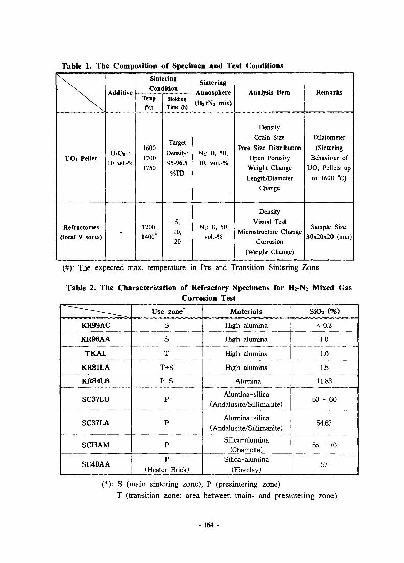
Table 1. The Composition of Specimen and Test Conditions
\
UOi Pellet
Refractories
(total 9 sorts)
Additive
U3O8 :
10 wt.-%
-
Sintering
ConditionTemp
fC)
1600
1700
1750
1200,
1400*
Holding
Time (h)
Target
Density.
95-96.5
%TD
5,
10,
20
Sintering
Atmosphere
(H2+N2 mix)
N2: 0, 50,
30, vol.-%
N2: 0, 50vol.-%
Analysis Item
Density
Grain Size
Pore Size Distribution
Open Porosity
Weight Change
Length/Diameter
Change
Density
Visual Test
Microstructure Change
Corrosion
(Weight Change)
Remarks
Dilatometer
(Sintering
Behaviour of
UO2 Pellets up
to 1600 °C)
Sample Size:
30x20x20 (mm)
(#): The expected max. temperature in Pre and Transition Sintering Zone
Table 2. The Characterization of Refractory Specimens for H2-N2 Mixed GasCorrosion Test
KR99AC
KR98AA
TKAL
KB81LA
KR84LB
SC37LU
SC37LA
SCHAM
SC40AA
Use zone*
S
S
T
T+S
P+S
P
P
P
P
(Heater Brick)
Materials
High alumina
High alumina
High alumina
High alumina
Alumina
Alumina-silica(Andalusite/Sillimanite)
Alumina-silica
(Andalusite/Sillimanite)
Silica-alumina(Chamotte)
Silica-alumina(Fireclay)
SiO2 (%)
i 0.2
1.0
1.0
1.5
11.83
50-60
54.63
5 5 - 7 0
57
(*): S (main sintering zone), P (presintering zone)
T (transition zone: area between main- and presintering zone)
- 164 -

2.1.2 Refractory corrosion test under various atmosphere and temperatureconditions
Refractory specimens for gas corrosion test to study the effects of sinteringatmosphere and temperature is shown in Table 2. The weight of the nine kinds ofrefractory specimens of 30x20x20 (mm) each were measured before and after thecorrosion test. Corrosion tests were performed under the various sintering atmospheressuch as 100% H2, 70%H2-30%N2 and 50%H2-50%N2, and at temperatures of 1200 and1400°C. Heating cycle for the corrosion test is shown in Fig. 2.
2.2 Test procedure of sintered UO2 pelletsTest procedure of sintered UO2 pellets is shown in Fig. 3 to investigate the effects
of sintering atmosphere and temperature on the microstructure of the UO2 pellets.
2.2.1 Specimen preparationThe chemical composition of UO2 and U3O8 powder is shown in Table 3. After
blending UO2 powders with 10% U3O8 for 2 hours, the blended powders werecompacted to green pellets with density of 5.6g/cm3. Commercially produced pelletswere also tested to compare the characteristics. The green pellets were sintered underatmosphere varying from 100% H2 to 50%H2+50%N2 and at temperature 1600°C,1700°C and 1750°C. Fig. 4 shows the sintering temperatures and holding times.
2.2.2 ExperimentImmersion density and open porosity of sintered UO2 pellets were measured with
commercial procedure. Pore size distribution was measured on the unetched specimensand grain size on thermal etched specimens with image analyzer system. The poreshape also was measured with SEM.
5°C/min1200 °C, 1400 °C
5hr, lOhr
Fig. 2. Heating Cycle of the H2-N2 Mixed Gas Corrosion Testing forRefractories
Table 3. The Chemical Analysis Results for the Uranium Oxide Samples
\
U3O,
U-235
Enrichment
(wt.%)
3.8
3.802
U-
content
(%)
87.460
84.790
O/U
ratio
2.106
2.654
Moisture
content
(ppm)
1370
620
BET
surface
(mVg)
5.57
0.53
Apparent
density
(g/cmJ)
2.20
-
Flowability
(sec /50g)
1.36
-
Particle
size
(%)
99.85
-
F-content
(PPm)
41
-
- 165-

U02 Powder
TZU3O8 Powder
Mixing (90%UO2+10%U3O8)
Weighing
- Open Porosity
Blending
Pelletizing
Sintering
(2hr)
(green density : 5.6g/cmJ)
(H2, H2+N2)
Surface Grinding
Drying
Image Analyzer
(600 X:, 2hr)
SEM
- Sintering Density - Grain Size
Pore Distribution- Pore Morphology
Fig 3. Schematic Diagram of Testing Procedure
1600 °C, 1700 °C, 1750 °C
5°C/min
Fig. 4. Heating Cycle for UO2 Pellets Sintering Test
- 166 -

3. Results and Discussion
3.1 Corrosion behavior of refractory materials
3.1.1 Thermochemical analysis resultsIn principle the reaction of Al2O3(s) and H2(g) may generate gas phases such as
AlH(g), OAlH(g), AlOOH(g), OAlOH(g) but, because these reactions occur at muchhigher temperature than sintering temperature, they are excluded in the thermochemicalanalysis. Although the reaction of SiCtys) and H2(g) may generate Si(s), SiO(g), Si(g),SiH4(g), SiH(g), SiO(g) and Si (s or g) are likely to be produced under low oxygenpartial pressure in the current testing condition. Equilibirum reactions in theAbCh-SiOi-fh reaction system may be written as follows;
1) Case 1 : A12O3 • SiO2 - H2
1-1. A12O3 • SiO2 + H2(g) = AI2O3 + SiO(g) + H2O(g)1-2. AI2O3 • SiO2 + 2H2(g) = A12O3 + Si + 2H2O(g)1-3. 2(A12O3 • SiO2) + 3H2(g) = 2A12O3 + SiO(g) + Si + 3H2O(g)
2) Case 2 : 3A12O3 • 2SiO2 - H2
2-1. 3AI2O3 • 2SiO2 + 2H2(g) = 3A12O3 + 2SiO(g) + 2H2O(g)2-2. 3AI2O3 • 2SiO2 + 4H2(g) = 3A12O3 + 2Si + 4H2O(g)2-3. 3A12O3 • 2SiO2 + 3H2(g) = 3A12O3 + SiO(g) + Si + 3H2O(g)
* all solid phase except (g)
3) Case 3 : for refractories containing SiCh as main constituents orincluding SiCh (s or 1) as main bonding phase
3-1. SiO2(s) + H2(g) = SiO(g) + H2O(g)3-2. SiO2(s) + 2H2(g) = Si(s) + 2H2O(g)
4) Case 4 : precipitation of SiO2 is not considered because of thedecomposition of AI2O3.
Considering the furnace operation conditions, the analysis was performed in thetemperature range from 1400K to 1900K and the z/G° values were calculated foreach component from JANAF table(Table 4). From the equations of 3-1 and 3-2,which are expected to react significantly, it seems that SiC>2 reacts with H2 gas toproduce SiO/H2O or Si/FbO. According to the AG° values, SiCh is likely to react toproduce SiO gas. Therefore weight loss is expected due to the evaporation of theSiO(g) and/or H2O(g), resulting refractory failures. The evaporation of SiO(g) and/orH2O(g) act as a oxygen source to the Mo-heating elements oxidation. From the abovethermochemical analysis, it can be summarized as follows;
- 167-

# Under 1 atm, Andalusite(Al2O3 • SiO2) and Mullite(3Al2O3 • 2SiO2) as stabilizingrefractory in the (Al2C>3-Si02) System and free SiO2, main bonding phase in theSilica brick, were selected.
# The decomposition of A12O3 into AlH(g), OAlH(g), AlOOH(g) were neglectedbecause these reaction were not shown and SiH^g) or SiH(g) was notconsidered in the reactions because JG°f value of the SiH4(g) or SiH(g) ismuch higher than that of SiO(g) and Si(s).
# All free energy change (zJG°reac.) in the equilibrium reaction (Table 4, eq. 1-1 ~2.3) for the high alumina brick at 1400K—1900K is very positive values, thatis, the stability of refractory is maintained under the hydrogen atmosphere atthese temperture ranges.
% For silica brick, all free energy change (zJG reac.) in the equilibrium reaction (eq.3-1 and 3-2) at 1400K—1900K is highly negative values. So, corrosion willoccur in the Silica Brick by hydrogen.
Fig. 5 shows AG reac curves of all equations with temperature.
100
600
500
=• 400
3.
P 300
:oo
100
0
^ ^ ^ ^ ^ ^
-sooDM lt»D 1500 lt.00 5*00 1900 :ooo 1300 1400 1500 1600 1700 1800 1900 2000
T (K) >
Fig 5. T-JG rca(. Diagram of the Thermochemical Analysis Results
- 168-

Table 4. The Calculated zJGVac. Values of the Possible Reactions [kJ/mol]
\ r e m p [ K ]^̂
Reaction N r \
1-1
1-2
1-3
2-1
2-2
2-3
3-1
3-2
1400
275.639
325.254
600.893
560.985
660.215
610.6
-72.424
-22.809
1500
256.081
319.302
575..383
525.287
651.729
588.508
-122.088
-58.867
1600
236.693
313.478
550.171
489.863
643.729
566.648
-171.995
-95.210
reac.
1700
217.466
307.321
524.787
454.685
634.395
544.54
-276.309
-186.454
1800
198.4
298.753
497.153
419.741
620.447
520.094
-330.374
-230.023
1900
179.49
290.308
469.798
385.012
606.648
495.83
-384.661
-273.843
PH2/PH2O
(at 1900K,Psio = 10"W)
8.6X10°
9.5 xlO3
8.2 xlO9
3.8 xlO6
4.7 xlO12
4.5 xlO9
2.7xlO"15
1.7xlO"4
3.1.2 Reaction of refractories with H2 gasTest temperatures of 1200 and 1400°C were selected because they might represent
the temperature range of 900~1400°C in the transition sintering zone showing mostfrequent refractory failure. Reactivity of refractory with H2 gas was analyzed underthe sintering atmosphere of 100% and 50% H2 gas with time of holding 5, 10 and15 hours at each temperature. The location in the sintering furnace is shown in Fig.1 for each testing specimen.
From the thermochemical analysis results, it was found that high alumina brickcomposed of AI2O3 and SiC>2 is not likely to react, while free silica is likely toreact and reduced by H2 gas. So, it is important to examine the SiC»2 phases in therefractories(Table 2) and the temperature at each zone(Fig. 1).
Corrosion-induced weight loss data are given in Figs. 6, 7 and Table 5 at varioussintering atmosphere and temperatures. From the Fig. 6, corrosion resistance wassignificantly increased by substituting hydrogen content with nitrogen by 50% underthe condition of 1400°C-10hrs. In particular, it was found that the weight loss wasreduced more than 2 times for pre- and transition zone refractories (KR84LB,KR81LA & SC37LU).
From the test results at 1200°C (Fig. 7 and Table 5), there were no significantdifferences with gas contents, but corrosion resistance was improved in most cases.
As shown in Table 5, weight loss was increased by increasing holding times at1200°C irrespective of gas contents. And also under 100% H2 atmosphere, weightloss was increased by increasing temperature from 1200°C to 1400°C. Under 50%H2 atmosphere, weight loss was increased by temperature increase in most cases, butfor Scham and SC37LU containing much SiO2 the weight loss was highest at1200°C.
- 169 -

Table 5. The Weight Loss (%) of Main Refractories Tested under H2-(N2) GasCorrosion Conditions
Test ^^-Sgecimen
Condition ^ \ ^
100% H2
50%H2-
50%N2
Mix
1200°C+5h
1200°C+10h
1200°C+20h
1400°C+10h
1200°C+5h
1200°C+10h
1200°C+20h
1400°C+10h
TKAL
0.0791
0.1235
0.1476
0.2837
0.0632
0.0980
0.1384
0.2539
SCHAM
0.2969
0.3161
0.3651
0.4608
0.2902
0.3121
0.3327
0.2429
SC37LA
0.8688
0.9912
1.0675
1.5755
0.8288
0.9627
1.0571
1.2136
SC37LU
0.5363
0.5690
0.6143
0.8178
0.4934
0.5362
0.5853
0.2424
KR81LA
0.0903
0.1154
0.1233
0.3067
0.0259
0.0664
0.1005
0.1231
KR84LB
0.0406
0.0472
0.0836
0.4915
0.0397
0.0459
0.0702
0.0732
SC40AA
(HB)
0.2662
0.2809
0.2926
-
0.2554
0.2579
0.2613
-
KR98AA
-
-
-
0.4009
-
-
-
0.2969
KR99AC
-
-
-
0.1317
-
-
-
0.0811
(-): not tested
1.00
0.80
0.60co
o
D) 0.40"a;
0.20
0.00
Refractories Refractories
Fig. 6. The Weight Loss of Refractoriesunder Various H2-(N2) Gas
Corrosion Conditions(1400°C+10h)
Fig. 7. The Weight Loss of Refractoriesunder Various Eb-(N2) Gas
Corrosion Conditions (1200°C+10h)
- 170-

3.2 Characteristics of sintered UO2 pellets
3.2.1 Sintering densitySintering was performed under the condition selected at temperature of 1600, 1700
and 1750°C, and atmosphere of 100% H2, 70%H2(+30%N2) and 50%H2(+50%N2).Sintering density of the testing and commercial pellets is shown in the Tables 6 and7 and Figs. 8 through 10, respectively. As shown in these tables and figures, exceptthe results at 1600°C, the sintering density of the pellets is almost constantirrespective of gas composition in the commercial sintering temperature range of1700-1750°C. Contrary to expectation, sintering density was slightly increased byreducing H2 contents, and the sintering density values were highest at 70% H2 gas fortesting and commercial pellets. From the testing results, it is concluded that the effectsof atmosphere on the sintering density is not significant in these testing temperatures.
10.45
10.43
CO
c 10.41Q
10.39
50%H2 + 50%N2
100%H2
i •
Fig. 8. The Density Change of Testing UO2 Pellets Sintered under Various SinteringAtmospheres (1700°C+5h)
10.49 1051
. 0
CO
Q
10.47
10.45
10.43
10.41
10.39
10.37
70%H9+30%N,
I I I
100%H;50%H?+50%N;
£o
cCDO
10.50
10.49
10.48
10.47
70% H2
1100%H2
+ 30%N
1•50%H2
2
•
1*+ 50%Na
Fig. 9. The Density Change of Testing Fig. 10. The Density Change of CommercialUO2 Pellets Sintered under Various UO2 Pellets Sintered under VariousSintering Atmospheres (1750°C+5h) Sintering Atmospheres (1750°C+5h)
- 171 -

Table 6. The Average Density Change of Testing Pellets Sintered underVarious Sintering Conditions
SinteringCondition
1600°C-10h
1700°C-5h
1750°O5h
MeasuredDensity*
DI
DII
DI
DII
DI
Std.Deviation
DII
Density (g/cm3 / %TD)
100 % H2
10.3985/94.8768
10.3326/94.2756
10.4200/95.0729
10.3758/94.6697
10.4349/95.2086
0.0092
10.3946/94.8412
70 % H2
-
-
-
-
10.4390/95.2466
0.0088
10.4192/95.0657
50 % H2
10.4391/95.2468
10.3923/94.8203
10.4209/95.0809
10.3859
/94.7619
10.4271/95.1379
0.0147
10.4149/95.0265
Remarks
• 0.37% TD increase in
50% H2
• 0.55% TD increase in
50% H2
• 0.01% TD increase in
50% H2
• 0.09% TD increase in
50% H2
• max. 0.11% TD increase
• max. density in 70% H2
• max. value in 50% H2
• max. 0.23% TD increase
• max. density in 70% H2
Table 7. The Average Density Change of Commercial Pellets Sintered underVarious Sintering Atmospheres
Sinteringcondition
1750°O5h
Measureddensity*
DI
Std. Deviation
DII
Density (g/cm3 / %TD)
100 % H2
10.4880/95.6935
0.0028
10.4516/95.3613
70 % H2
10.4903/95.7142
0.0041
10.4575/95.4151
50 % H2
10.4870/95.6846
0.0037
10.4607/95.4443
Remarks
• max. 0.02% TD increase
• max. density in 70% H2
• max. density in 70% H2
• max. 0.08% TD increase
• max. density in 50% H2
(#) DI: density measured by Archimedes methodDII: density considered open porosity mesurement
- 172 -

3.2.2 Open porosityAverage Open porosity values of the pellets sintered at various condition are shown
in Tables 8 and 9. From these tables it is seen that most of pellets sintered at50%H2-50% N2 gas show the microsture containing less open porosity. Also, in thesame sintering condition, it is seen that the least open porosity is obtained at the70%H2-30% N2 gas atmosphere.
Table 8. The Average Open Porosity Change of Testing Pellets Sintered underVarious Sintering Conditions
Sintering Condition
1600°C-10h
1700°C-5h
1750°C-5h
Open Porosity (%)
100 % H2
3.401
2.662
1.841
70 % H2
-
-
1.617
50 % H2
2.479
2.494
1.843
Remarks
Table 9. The Average Open Porosity Change of Commercial Pellets Sinteredunder Various Sintering Atmospheres
Sintering Condition
1750°C-5h
Open Porosity (%)
100 % H2
0.114
70 % H2
0.078
50 % H2
0.088
Remarks
3.2.3 Pore size distribution and shapePore size distribution measured by an image analyzer is summarized in Table 10.
From this table, all pellets have monomodal type pore size distribution irrespective ofsintering conditions, show peaks located in the range of 0.5~1.5//m and consist ofvery typical fine pores with average pore size of 1.5~1.9/mi for all specimens. It isconcluded that the pore structure is not affected by gas content variation within thetest ranges.
3.2.4 Grain sizeGrain sizes of the sintered pellets measured by an image analyzer and their >
metallograpy is summarized in Table 11. The pellets sintered in pure H2 gas showgrain growth earlier than pellets sintered in the H2-N2 mixed gas.
- 173 -

Table 10. The Change of Pore Size Distribution for UO2 Pellets Sintered underVarious Sintering Conditions
Test Pellets
CommercialPellets
SinteringCondition
1600°C
+ 10h
1700°C
+5h
1750°C
+5h
1750°C
+5h
Type ofPore Size
Distribution
Monomodal
Monomodal
Monomodal
Monomodal
Max. fraction (%)(Average Pore Diameter, /nn)
100% H2
• 0.5-1.0//m: 30• 1.0-1.5// m: 27
(1.9)
•0.5-1.0fitn- 29• 1.0-1.5// m: 29
(1.9)
•0.5-1.0// m: 36• 1.0-1.5//m: 32
(1.6)
•0.5-1.0//m: 30• 1.0-1.5//m: 32
(1.7)
70% H2
-
-
•0.5-1.0// m: 34•1.0-1.5//m: 31
(1.6)
• 0.5-1.0 //m: 32• 1.0-1.5// m: 32
(1.6)
50% H2
•0.5-1.0//m: 30• 1.0-1.5// nv 28
(1.8)
•0.5-1.0//m: 30• 1.0-1.5//m: 29
(1.8)
•0.5-1.0// m: 31• 1.0-1.5// m: 32
(1.7)
•0.5-1.0//m: 34• 1.0-1.5// m: 34
(1.5)
Table 11. Grain Size Change of Pellets Sintered under Various SinteringConditions
Test Pellets
CommercialPellets
Sintering Condition
1600"C+10h
1700°C+5h
1750°C+5h
1750°C+5h
Average Grain Size (//m)
100% H2
5.3
7.7
7.9
7.6
70% H2
-
-
6.3
6.4
50% H2
5.5
6.3
6.5
6.4-
- 174 -

4. Conclusion
The effect of various sintering atmospheres on thermochemical behavior of main-refractory materials of the UO2 sintering furnace and on microstructure of sinteredUO2 pellets have been investigated.
Thermochemical analysis for the refractory materials was performed for the reactions3Al2O3-2SiO2, Al2O3-SiO2, free SiO2(s) + H2(g) -> Si(s) or SiO(g) and H2O(g) (1400-1900K, all 100 K). It was found that Mullite (3Al2O3-2SiO2) and Andalusite/Sillimanite (Al2O3'SiO2) which are main constituents in the Transition Sintering Zonehad low possibility of pure H2 gas-induced reduction, whereas Fire Clay and Chamottein the Presintering Zone which are composed of SiO2 bonded with AI2O3 or freeSiO2 had high possibility of pure H2 gas-induced reduction. This is because Fire Clayand Chamotte have negative free energy change over the test temperature, whileMullite and Andalusite/Sillimanite positive free energy change.
In order to investigate the effect of mixed gas on the H2 gas-induced reduction ofthe refractory materials, two kinds of mixed gas such 70%H2-30%N2 and50%H2-50%N2 was used. The H2-N2 mixed gas experiment showed that the largeramount of N2 retarded the H2-induced reduction rate of the refractory materials withthe increasing sintering temperature. The 50%H2-50%N2 mixing gas indicated theH2-induced corrosion improvement of thermochemical gas corrosion (weight loss)resistance improvement of about 50% at 1400°C but negligible improvement at1200°C.
On the other hand, the H2-N2 mixed gas had negligible impact on microstructureand properties of UO2 pellet such as density, grain size, pore size distribution andopen porosity.
UO2 pellets showed almost constant density values irrespective of test sinteringatmosphere and slightly higher values in both grain size and open porosity under pureH2 sintering atmosphere above 1700°C. For pore size distribution it was foundmonomodal type distribution with peak values at 0.5 — 1.5 /m independent of sinteringatmosphere and no significant difference in pore shape.
It can be concluded that reducing of H2 content in the sintering atmosphere stronglycontribute to diminish the failure of refractory materials and the effect of the H2-N2
mixed gas on microstructure of the UO2 pellet is not significant in the test ranges.
References
[1] M.S. Crowley, Am. Ceram. Soc. Bull., 46 (1969), 679-682[2] Kiyosh Naito, Masumi Toda and Toshihiro Kakehi,
Shinagawa Fire Brick Co. Tech. Report, 16 (1970). 55-73[3] Stephen T. Tso and Joseph A. Pask, J. Am. Cearm. Soc, 65 (1982), 457-460[4] Stephen T. Tso and Joseph A. Pask, J. Am. Cearm. Soc, 65 (1982), 383-387[5] Technical Report, KNFC/TR-031/95
. 175 -I left BLANK

KR9700379
The ¥ Seminar on the New Fuel Technology Toward the 21 Century,
November 25 - 26, 1997, KAER1, Taejon, Korea
Development of Fabrication Process and Equipments forAdvanced-feature Fuel Pellet
Young-Woo Lee, Si-Hyung Kim, Han-Soo Kim and Sang-Ho NaKorea Atomic Energy research Institute
P.O.Box 105, Yuseong, Taejon 305-600 Korea
Abstract
The processes of UO2 fuel pellet and other related binary mixture are reviewed inthe aspect of microstructural homogeneity when UO2 is mixed or doped and sinteredwith different oxides for advanced-feature fuel pellets. Among the three differentconcepts of powder mixing, mechanical blending, Masterblending(MB) and Single StepFinal Compaction Milling(SSFCM), SSFCM showed the highest degree ofhomogeneity. Dopants for microstructure control are also considered forhomogenization in the aspect of solid solution formation. The equipment developmentsfor mixing process was pursued to overcome the disadvantages which give rise to theproblem especially when handling radioactive materials. An example is given for thecontinuous two-stage attrition mill.
1. Introduction
UO2 fuel is used worldwide mostly in sintered pellet form for various types ofcurrent nuclear power reactors due to its positive in-reactor performance andwell-established manufacturing technology. The sintered uranium dioxide is very stablein almost any room-temperature circumstances which involve mechanical and physicalbehaviors and radiation-resistant behavior, compared with its metallic phase or otherceramic compounds such as nitride and carbide.
The use of UO2 for nuclear fuel goes back to as early as mid-1940's historically,when the U.S. Shippingport nuclear reactor came first into the operation and sincethat time on, the researches n UO2 and other related phases have been undertaken inas many aspects as where its properties were involved for nuclear fuel : materials andproperties, irradiation behavior, nuclear physics, chemical behavior in relation fuelcycle consideration. Hence, UO2 technology is nowdays commercially well-developedand available for mass production to supply fuels for operating commercial nuclear
- 177-

power plantsFuel cycle studies have been also performed including reprocessing and recycling
of the spent nuclear fuel which involve the separation of U and Pu and re-use ofthese fissile materials in commercial reactors.
The nuclear fuel can be burnt to a higher burn-up and to a longer extent if thefuel material properties can withstand such circumstances and hence, currently, studiesare directed to the higher and extended burn-ups by considering its in-pile behavior ofwhich significant knowledges and database have been accumulated during severaldecades.
For the points that are mentioned above, technologies available for UO2 fuel pelletcurrently employ doping of UO2 with additives to control and improve the pelletmicrostructure for higher and extended burnup, mixing desirable burnable poisons withUO2 and even mixing UO2 with PuO2 for its re-use in thermal reactors.
This paper deals the developmental works associated with the fabrication of theseadvanced-feature fuel pellet, i.e., mixing of different oxide materials with UO2, and tocontrol and obtain the microstructure of the UO2 matrix desirable for in-pile behavior.Larger grains and proper porosities and their distributions in these pellet microstructureare to a larger extent pursued by doping with additives in the case of pellets for highburn-up. Micro-homogeneity in the pellet is the key feature when mixing UO2 withdifferent oxide phases such as Gd2O3, Er2O3 and PuC>2 to form solid solutions.
2. Process development
Processes currently employed for manufacturing fuel pellet are so-called conventionalceramic process : i.e., cold pressing and sintering. For UO2 fuel pellet, a single oxidesintered phase, depending on the powders used, can be obtained by compaction ofhyperstoichiometric UO2 powder with or without any powder pre-treatment, andsintering perferably in reducing atmosphere at sufficient high temperature to bestoichiometric and of sintered density higher than 95%T.D.
If UO2 is to be doped or mixed with different oxides, the ceramic processemployed for UO2 pellet can still be used : however, a step for doping or mixingwould be added somehow during the process. The simplest method that can thus beconsidered is mixing two materials before powder compaction step. Several fuelindustries, based on much research results related to powder mixing and milling,currently employ various alternatives depending mainly on their own furtherdevelopments.
2.1 Powder mixing and homogeneityFig. 1 shows schematic process flow diagrams for UO2 pellet fabrication(l(a)) and
additive-doped UO2 pellet fabrication(l(b)), currently employed in the most fuelmanufacturing industries. Simple mechanical mixing or blending operation is frequentlyused through electrically driven mechanical mixer in case of doping with additives
- 178 -

Milling operation is often used when the required homogeneity is not achievablethrough simple mechanical mixing and hence, the resultant pellet microstructure cannot be satisfactory. As is the case for Mixed Oxides such as (U-Pu)O2, U02-Gd203 orUO2-Er2O3 which have fairly high contents of secondary oxides (typically 5-10%wt),two different powder materials are not only mixed through mechanical blending butalso milled to obtain a micro-homogeneity between two materials. As a matter of fact,the homogeneity of the powder mixtures greatly influences the microstructuralhomogeneity of pellets after sintering and the formation of solid solution.
The inhomogeneity can be overcome by several different techniques such as byusing Masterblend(MB) concept and Single Step Final Composition Milling(SSFCM)concept. Examples of these different techniques are: MTMAS(MIcronizedMASterblending) and OCOM(Optimized CO-Milling) processes for MB concept andSBR(Short Binderless Route) and CoCA(Co-broyage a CAdarache) processes forSSFCM concept currently employed in Plutonium Mixed Oxide manufacturingindustries worldwide[l,2,3].
In the Fig. 2 are shown the process flow diagrams for these two differentconcepts for the case of UO2-PUO2 Mixed Oxide pellet. In the MB concept(Fig. 2(a)),the first mixture of higher content(typically 25-30%wt) of powder to be added andmixed(PuO2, in this case) is made, which is so called Masterblend, by utilizing anintensive milling operation, and then the mixture of final composition is made byfurther addition of the original raw powder(UO2, in this case) an mechanical blending.In the SSFCM concept(Fig. 2(b)), the mixture of final composition is made in onestep also by utilizing an intensive milling, avoiding any further mixing operation.
For the burnable poison fuel pellet in particular, industries employ only mixingoperation taking either of the above explained two different concepts. This may causethe inhomogeneity and insufficient formation of solid solution by insufficientmicro-homogeneity through simple mixing operation.
Recent results of several observations[4,5] showed that even with MB concept, therewere fairly large inhomogeous regions in the pellet and second phase-rich regions tookplace, when applied to UO2-PUO2 Mixed Oxide pellet manufacturing. This leads to amore detailed study in mixing of two different oxides and give a tendency to adoptthe SSFCM concept which gives relatively high degree of homogeneity in solidsolution formation and microstructural aspects.
Fig. 3 shows an example of pellet microstructures obtained following three differentroutes: by simple blending, masterblend concept and single step final compositionmilling concept. The materials used in this study are UO2-4wt%CeO2, for both oxidesare known to form a complete solid solution. As is shown in the figures, in themicrostructure obtained by simple mixing(Fig. 3 (a)), one can clearly observeagglomerates of small grains which imply that CeO2-rich regions exist, large pores andgrain pull-outs. The average grain size is also very small (about 3 or" 4#m) comparedwith the required values(about 8//m). This microstructure is likely due to itsinhomogeneity originated from the insufficient powder microhomogeneity.
In the microstructure with MB concept(Fig. 3(b)), agglomerates of small grains are
- 179-

clearly reduced in area but still remain to a lesser extent compared with the formerThis implies that the agglomerates existing in small portion can be due to the finalmixing step to make the mixture with the final composition. The grain size does nots*eem to increase either, however the pores and their distribution are fairly even.Above inhomogeneous features in microstructure is much improved when the SSFCMconcept is taken(Fig. 3(c)): grain size is measured 7 jam in average, larger comparedwith the above two results and microstructure does not seem to reveal muchinhomogeneous feature, but still there exist some agglomerates of smaller grains.
2.2 Microstructure control in sinteringHomogeneity in microstructure is inherently controlled during sintering by
inter-diffusion characteristics of cations when two different oxides are mixed andsintered in high temperatures. Thus, increase of the diffusivity of the cations involvedin the material phases is very effective in mircrostructure control and homogenization.In the aspect of material science, the ways frequently adopted for increasing thediffusivities of cations in the system are use of sintering additives and/or increase ofthe oxygen potentials, for cations involved in the rate-controlling diffusive species todiffuse more easily. These techniques are also valid for control of microstructures suchas grain growth and porosity distribution.
There have been extensive studies on the effect of additives in the sintering ofUO2 and other UO2-related phases. Among the additives, Nb2Os[6] and TiC>2[7,8] arethe most promising additives to enhance the grain growth in UO2 sintering. Aluminumcompounds are also known as a dopant to grow the grains in UO2 sintering.
Recently, aluminum distearate(ADS) has been selected for both grain growth andlubrication in compaction step and tested in UC>2[9] and Gd-containing burnable poisonUO2 fuel pellet[10], showing positive results for its effects on the grain growth andhomogeneity improvement in the case of UO2-Gd2C>3 fuel pellet. Ta2Os and Li2O arefound the most effective dopants in UO2 published in recent literatures[ll,12], as faras the grain growth is concerned, exhibiting a strong enhancement of grain growth.Fig. 4 shows the example of microstructures for Ta- and Li-doped UO2. As can beobserved, while Ta-doped UO2 reveals both grain growth to about 50[m and effectivedensification leaving very little pores after sintering, Li-doped UO2 shows grain growtheven to a larger extent compared with Ta-doped UO2 but leaving large portion ofporosities. This may due to the evaporation of Li2O during sintering. The mechanismresponsible for such behavior and the effect on other properties are not yet completelyelucidated, and detailed analyses are currently in the progress.
The above-mentioned additives are also likely to be applied to the binary systemssuch as UO2-PUO2 and UO2-Gd2O3 or IKVE^Qj. Nevertheless, no additive has beenshown to increase grain size and improve their homogeneity except Li2O of which theeffect on grain and pores are simulatedly shown Fig. 5. The system chosen for thisstudy is known to simulate the UO2-PUO2 to a large extent with up to 30% of PuO2Compared with the microstructure of sintered UC>2-4wt%CeO2 without Li2O, shown inFig. 3(c), grain size is about 4 times larger in average but, again, leaving relatively
- 180-

big intergranular pores depending on the amout of LJ2O added.
3. Equipment development
In section 2.1, it was shown clearly the different levels of homogeneity to beobtained by 3 different concepts of mixing methods, namely ; simple mechanicalblending, Masterblending and Single Step Final Composition Milling, from whenceSSFCM can be recommended to be the most effective. In the powder millingoperation, which is usually dusty when operated in dry method, there have beendeveloped several milling equipments following how milling media and driving systemwere used: e.g., with a variety from simple ball-mill to plenetary mill or jet-mill.Nuclear fuel laboratories frequently use simple ball-mills, attrition mills or vibratorymills among which the attrition mill was found to be the most effective in sizereduction as well as in homogeneity achivement[13].
The milling operations sometimes give rises to the disadavantage that, whenpowder becomes fine, a large portion of powders milled during the operation inmilling media has tendency to be sticked to the wall inside the mill jar and will notmove following the milling sequence, and hence decrease the effectiveness of millingoperation. This may also give problems of handling and radioactive hazards especiallywhen handling nuclear materials.
A simple attrition mill consists of a motor-driven rotating shaft with paddles invertical center and a cylindrical mill jar in which milling media and the powders tobe mixed and milled are put together in an appropriate proportion. During millingoperation, the powders move to the center of the mill jar where the shaft turns andcome downward to the bottom. Then the powders continue to move to the peripheryfrom the center of the bottom and go upward until they move again towards thecenter of the upper part of the mill jar. During the trajectory of powder bulk, if therevolution of the shaft increases to get a maximum milling effect, powder tends tostick to the wall by a combined force from movements of milling media and shaftrevolution.
In order to reduce this disadvantage, continuous two-stage attrition mill isdeveloped with an improvent of function of paddles attached to the shaft, as shown inFig. 6. Fig. 6(a) gives a schematic diagram of multi-functional paddles and Fig. 6(b)shows the whole feature of the improved attrition mill for continuous two-stagemilling operation.
4. Summary
For the development of nuclear fuel pellet fabrication technology, both the processand the equipment to be used in the process should be simultaneously developed asthe process to be adopted and establishment of process parameters are based upon the
- 181 -

equipment to be used.For the fabrication processes used in UCb-related binary mixture fuel pellets, a
desirable homogeneity of these mixtures can be obtained either by selecting anappropriate mixing technology or by developing sintering technologies through the useof sintering additives and/or sintering atmosphere, or by combining these threetechnologies. Examples of results obtained by some of these technologies such assimple mechanical blending and two different concepts using intensive milling aregiven. Dopants are also considered for such microstructural homogenization. Severalcases are analysed by using simulated materials.
Equipment development must be continued and follow the process developmentbased on the technologies currently employed and in any time the problems areencountered. An example of developmental work for powder milling equipment isgiven here to avoid problems associated with powder sticking to mill container bycontinuous two-stage attrition mill.
References
[I] R. Giildner and H. Schmidt, J. of Nucl. Mater, 178 (1991) 152[2] H. Bairiot et al., ibid., 187[3] H. M. MacLeod and G. Yates, Nucl. Tech., 102 (1993) 3[4] C. T. Walker et al., J. of Nucl. Mater., 228 (1996) 8[5] idem., ibid., 245 (1997) 169[6] Y. Harada, ibid., 238 (1996) 237[7] Hj. Matzke, ibid., 20 (1966) 252[8] J. B. Ainscough et al., ibid., 52 (1974) 191[9] Y.-W. Lee et al., KAERI Tech. Rpt. KAERI/TR-381/93, 1994[10] J. H. Baek et al., Korean J. of Mater. Res., 5 (1995) 644[II] H. S. Kim et al., J. of Korean Nucl. Soc, 28 (1996) 458[12] S. H. Kimet al., Proc. Korean Nucl. Soc. Spring Mtg., vol. II, 74. Kwangju,
Korea, May 30-31, 1997[13] Y.-W. Lee et al., Proc. Korean Nucl. Soc. Fall Mtg., vol. II, 640. Seoul, Korea,
Oct. 28, 1995
- 182 -

uo2
Granulation
Precompaction
Crushing
Sieving
t
Compaction
CenterlessGrinding
uof dopant J
Compaction
CenterlessGrinding
Fig. 1. Schematic fabrication flow diagrams for :(a) UO2 pellet and (b) additive-doped UO2 pellet
- 183 -

Masterblend Process Single Step Process
uo2
PuO2
(Gd2O3)(Er2O3)
Blending(30mol%Gd2O3)
Milling
Blending(5mol%Gd2O3)
Compaction
Sintering
CenteriessGrinding
UO2
Granulation
PuO2
(Gd2O3)
(Er2O3)
Milling(5mol%Gd2O3)
Blending
Spheroidizing
Compaction
Sintering
CenteriessGrinding
Fig. 2. Schematic fabrication flow diagram following :(a) Masterblending concept and(b) Single Step Final Composition Milling
- 184-

5
(a)
Fig. 3. Different microstructures of sintered UO2-3.25wt%CeO2 pellet
following :(a) mechanical blending, (b) Masterblending and(c) Single Step Final Composition
Milling

I,/ \
(a)
(b)
Fig. 4. Examples of microstructures of additive-doped UO2
(a) Ta2O5-doped UO2 and (b) Li2O-doped UO2
- 186 -

Fig. 5. Microstructure of Li20-doped UO2-3.25wt%CeO2
- 187-

(a)
(b)
Fig. 6. Continuous two-stage attrition mill(a) shaft with paddles and (b) assembled attrition mill
- 188 -

KR9700380
The 2™̂ Seminar on The New Fuel Technology Toward The 21 Century
November 25-26, 1997, KAERI, Teajon, Korea
Development of Coating Technology for Nuclear Fuel bySelf-propagating High Temperature Synthesis
Y. Choi*, Bong G. Kim and Y. W. Lee
* Sunmoon University, Asan, Chung Nam 336-840, KoreaKorea Atomic Energy Research Institute, Taejeon, 305-353, Korea
Abstract
This paper presents experimental results of the preparation of silicon carbide and graphitelayers on a nuclear fuel from silane and propane gases by a conventional chemical vapordeposition and combustion synthesis technologies. The direct reaction between silicon andpyrolytic carbon in a high temperature releases sufficient amount of energy to make asynthesis self-sustaining under the preheating of about 1200°C. During this high temperatureprocess, lamellar structure with isotropic carbon layer and beta-silicon carbide layer was wellformed by self-propagating high temperature synthesis. A full characterization of phasecomposition and final morphology of the coated layers by X-ray diffraction, SEM and AESis presented.
Introduction
Coating on a nuclear fuel is one of methods to enhance the safety and reliability of thenuclear fuel.[1,2] The coating layers contains pyrolytic carbon, silicon carbide and zirconiumcarbide layers. Since the most important function of the pyrolytic carbon layer on a nuclearfuel is to retained the fission products generated during reactor operation and prevent coolinggas contamination, pyrolytic carbon layers with a desirable neutron irradiation behaviors andstructural integrity are required to be prepared. The good neutron irradiation behavior andreliable strength of the carbon layer are obtained when its microstructure is so called,"carbon-black-like component (CBC), which contains the ratio and the distribution of orderedand disordered carbon in the pyrolytic carbon. To fulfill this function like withstanding theloads, the pyrolytic carbon is produced from such hydrocarbons as methane, propylene andacetylene by thermal deposition.[3] Silicon carbide layer on the nuclear fuel for hightemperature gas cooled reactor acts as a diffusion barrier and prevents radioactive fissionproducts from migrating into the coolant circuit. [4] The silicon carbide is well prepared bythe thermal decomposition of various source gases including methychrolosilane and methane,acetylene and propane at high temperatures above 1400°C. Considering the irradiation effect
- 189-

and thermal and mechanical properties for the application of nuclear fuel, P-SiC with finecolumnar grains is optimum microstructure, which is normally formed at the thermaldeposition temperature range of 1600 and 1700 °C. This kind of high deposition temperature
-resulted in introducing structural defects in the layers and difficulties to operate theproduction systems in the field. It is known that the silicon carbide is also well preparedwith relatively low thermal shock by a combustion synthesis between silicon and graphite.This study was initiated to develop unique coating technology including a combustionsynthesis reaction and to prepare the pyrolytic carbon and silicon carbide layers for a nuclearfuel. A full characterization of phase composition and final morphology of the coated layersprepared by a combustion synthesis reaction was carried by X-ray diffraction, SEM and AES.
Experimental procedure
Figure 1 shows the schematic diagram of the carbon deposition unit, which consists of a1500 kW resistance furnace, a preheater of the source gases, a gas mixer to prepare mixinggases, temperature controller, and gas controller systems. Inside of the furnace, a coater witha cone angle of 60° chamber and 300 mm in length is installed. The total gas flow dunngeach experiment maintained constant by gas flow meter and mass flow controller.Propanc(99.9%) and argon gases were used as a carbon source and a earner gas. respectively.The total pressure in the coating chamber was 1 atm. The source gas and earner gases wereblended in a gas mixer with various compositions and preheated at 400 °C in pre-heaterbefore flowing into the coater. The coating temperature was measured by Pt/Pt-5% Rethermocouples contacted to the graphite coater in the furnace. Coating conditions employed inthis study are shown in Table 1.
The silicon was deposited on dummy fuels with spherical and cylindrical shapes withECR PECVD unit., which contains 3-dimensional coating stage as shown in Fig. 2.Expenmental method is mentioned in detail in the previous study [7]. Combustion reactionbetween silicon and carbon was carried out by igniting with heating coil after preheatingabove 1000°C. During the reaction combustion behavior was observed with a video camera.The phase identification of the deposits was performed with a X-raydiffractometer(MXP3A-HF2000) and an auger electron spectroscope(VG 2400). Themicrostructure of each deposit was observed by scanning electron microscopy (Jeol 6400).
Results and discussion
Figure 3 is a cross section of a coated fuel, which shows the uniform coating layer onthe substrate Figure 4 shows x-ray diffraction pattern of the bottom coated layer, which istypical carbon spectra. Figure 5 is the top and cross sectional views of the carbon layerobserved by SEM. The thickness of the pyrolytic carbon was about 100 |im. As shown infigure 5, the morphology of pyrolytic carbon is round shape with isotropic structure.
Figure 6 shows the effects of the composition of flow gas and the coating temperature onthe pyrolytic carbon deposition rate with various total flow rates. Deposition rate increasedas both the temperature and the flow rate increased. The temperature dependence of thedeposit layer is related to the thermal decomposition of propane. The propane can be
- 190 -

thermally decompensates above the temperature of about 900°C.[6] Since the decompositionprocess is endothermic, the increased coating temperature resulted in enhancing thedecomposition process. The denser carbon content in the flow gas produced the thicker coatedlayer due to the amount of carbon in the flow gas, which was thermally decomposed insidethe coater. Although the density of the coated layer was not determined in this study, it isclear that the deposition rate was significantly dependent upon the thermal decomposition ofcarbon in the source gas.
Figure 7 is the combustion wave propagating behavior observed by video camera. Thecombustion reaction between silicon and graphite was well occurred after preheating above1200°C followed by a ignition with tungsten heating coil. Figure 8 is the surface morphologyof the silicon layer. The morphology is round shape with average diameter of about 1.0 pm.Figure 9 is the EDX spectra of the each layer. Inner and outer layer show typical graphiteand silicon carbide spectra, respectively. Figure 10 shows the X-ray diffraction patternof the top layer before and after combustion reaction P-SiC was formed after the combustionreaction. Figure 11 is auger spectra of the deposit surface after combustion reaction. Asshown in figure 11. a typical silicon carbide spectra was observed. Comparing figures form 8to 10, lamellar structure with isotropic carbon layer and beta-silicon carbide layer was wellformed by self-propagating high temperature synthesis. Since the isotropic microstructure ofpyrolytic carbon and beta-silicon carbide is recommended structure for the coated nuclear fuel,the coating technology selected in this study is useful for the preparation of the coatednuclear fuels.
Summary
To develop coating technology for the preparation of coated nuclear fuel, a microstructureevaluation of the coated layers prepared by chemical vapor deposition and combustionsynthesis reaction was carried out with XRD, SEM, EDX and AES. The uniform andrelatively homogeneous deposition was formed on dummy fuels. The pyrolytic carbon withabout 100 nm thickness has isotropic structure with spherical morphology. The deposition rateof pyrolytic carbon was about 11 Jlm/hr. in the flow gases containing Ar-30% C3H8 gas at1300°C with 2.0 1/min. of total flow rate. Silicon layers has also fine round grains. Thedeposition rate was depended on the microwave frequency. After combustion reaction betweentwo layers, isotropic carbon layers with beta-silicon carbide was prepared. This process makesdesirable microstructure for the coated nuclear fuel considering the structure integrity andneutron irradiation behavior.
REFERENCES
[1] Ceramic Source Book, vol. 6, 1990-91, The American Ceramic Society, Inc.[2] Y. Choi, J. W. Lee, Y. W. Lee and D. S. Sohn, Journal of the Korean NuclearSociety, vol. 28(1), 1996, pp. 225-230.[3] E. A. Wofrum and H. Nickel, Nuclear Tech., vol. 35(2), 1977, pp 293-300[4] R. J. Price, Nuclear Tech., vol. 35(2), 1977. pp. 320-336[5] Yu M. Grigorev and A. G. Merzhanov, International Journal of SHS, vol. 4, 1992,
- 191 -

pp. 600-642.[6] H. Huschka and P. Vygen, Nuclear Tech, vol. 35(2), 1977, pp. 238-245.
Table 1. Coating conditions of pyrolvtic carbon
deposition temperature [°C]total flow rate [//minicomposition of source gas [%]total weight of specimen installed [g]size of each sample [mm]preheating temperature [°C]cone angle of coater [degree]size of coater [mm]cone angle of distributer [degree]size of distributer [mm]nozzle size of distributer [mml
1100-13001.5-2.05-3080dia. 2.040060ID 50x30060ID 23x2010
- 192 -

JMIXER > I
Z
IGNITION
PRK-HLATt.R 400 C" MAX
Fig. 1. Schematic diagram of the coating unit.
Fig. 2. Photographs of operating mechanism of 3-dimensional coating unit of ECRPECVD
- 193-

Fig. 3. Cross sectional view of a coated fuel
2000
I? 25 35 45 55
I V%II Ihcla | Degrees 1
Fig. 4. X-ray diffraction spectra of the bottom coated layer
- 194 -

(a)
(b)
Fig. 5. Scanning electron micrographs of pyrolytic carbon layer(a) top (b) cross section
- 195-

1050 I 100 1150 1200 1250
Temperature [°C]1350
Fig. 6. Effects of the composition of flow gas and the coating temperatureon the deposition rate ( O : 33% of C3H8 # : 25 % of
Fig. 7. Combustion wave propagation behavior observed by video camera
- 196 -

80000
a.U
— 40000 1
20000
Fig. 8. Scanning electron micrograph of silicon layer
:<HHJO —
— 15000
— 10000
-1 h 8 ID 1
Energy | K c V |
M '• IK
(a)
4 6 8 10 12 14 16 IS
Energy |KeV|
(b)
Fig. 9. EDX spectra of the interface layers (a) bottom (b) top
- 197 -

500
ycj 400
300
>>- 200c
100
0
—
-—
"" = i— CM
SiC
(lll)
CO.
1<!;lik
\
JL
si
« 1
y
e
c§CM
o
liy
JLLL
y
. 1
ocTSas
20 30 40 50 60 70
Two Theta [Degrees]85
Fig. 10. X-ray diffraction spectra of the coated layer after combustion reaction
0 200 400 600 800 1000 1200 1400 1600
Kinetic Energy [cVJ
Fig. 11. Auger spectra of the coated layer
- 198-