kubota rtv 500 utility vehicle - operators manual · some small parts of this manual to become...
TRANSCRIPT

1AYAAAYAP0030
READ AND SAVE THIS MANUAL
OPERATOR'S MANUAL
UTILITY VEHICLE
RTV500
English (U.S.A.)Code No. K7311-7122-3
PRINTED IN U.S.A. © KUBOTA Corporation 2008
Downloaded from www.Manualslib.com manuals search engine

KUBOTA Corporation is ···Since its inception in 1890, KUBOTA Corporation has grown to rank as one of the major firms in Japan.
To achieve this status, the company has through the years diversified the range of its products and services to a remarkable extent, until today, 19 plants and 16,000 employees produce over 1,000 different items, large and small.
All these products and all the services which accompany them, however, are unified by one central commitment. KUBOTA makes products which, taken on a national scale, are basic necessities. Products which are indispensable, products intended to help individuals and nations fulfill the potential inherent in their environment. For KUBOTA is the Basic Necessities Giant.
This potential includes water supply, food from the soil and from the sea, industrial development, architecture and construction, transportation.
Thousands of people depend on KUBOTA's know-how, technology, experience and customer service. You too can depend on KUBOTA.
Abbreviations Definitions
ABBREVIATION LIST
California Proposition 65
WARNING
IMPORTANT
The engine in this machine is equipped by the manufacture with a standard spark arrester.It is a violation of California Public Resource Code Section 4442 to use or operate this engine on or near any forest-covered, brush-covered land, or grass- covered land unless the exhaust system is equipped with a working spark arrester meeting state laws. Other states or federal areas may have similar laws.
The engine exhaust from this product contains chemicals known to the State of California to cause cancer, birth defects or other reproductive harm.
Two Wheel Drive
Four Wheel Drive
American Petroleum Institute
American Society of Agricultural and Biological Engineers, USA
American Society for Testing and Materials, USA
Deutsches Institut für Normung, GERMANY
Feet Per Minute
Hydrostatic Transmission
Kilometers Per Hour
Miles Per Hour
Meters Per Second
Power Take Off
Right-hand and left-hand sides are determined by facingin the direction of forward travel
Roll-Over Protective Structures
Revolutions Per Minute
Revolutions Per Second
Society of Automotive Engineers, USA
Variable Hydro Transmission
2WD
4WD
API
ASABE
ASTM
DIN
fpm
HST
Km/h
MPH
m/s
PTO
RH/LH
ROPS
rpm
r/s
SAE
VHT
Downloaded from www.Manualslib.com manuals search engine

UNIVERSAL SYMBOLSAs a guide to the operation of your vehicle, various universal symbols have been utilized on the instruments and controls. The symbols are shown below with an indication of their meaning.
Safety Alert Symbol
Engine Coolant-Temperature
Brake & Parking Brake
Battery Charging Condition
Engine Oil-Pressure
Turn Signal
Engine-Stop
Engine-Run
Engine-Diagnostic
Starter Control
Differential Lock
Master Lighting Switch
Headlight
Audible Warning Device
Four-Wheel Drive-On
Four-Wheel Drive-Off
Lock
Unlock
Downloaded from www.Manualslib.com manuals search engine
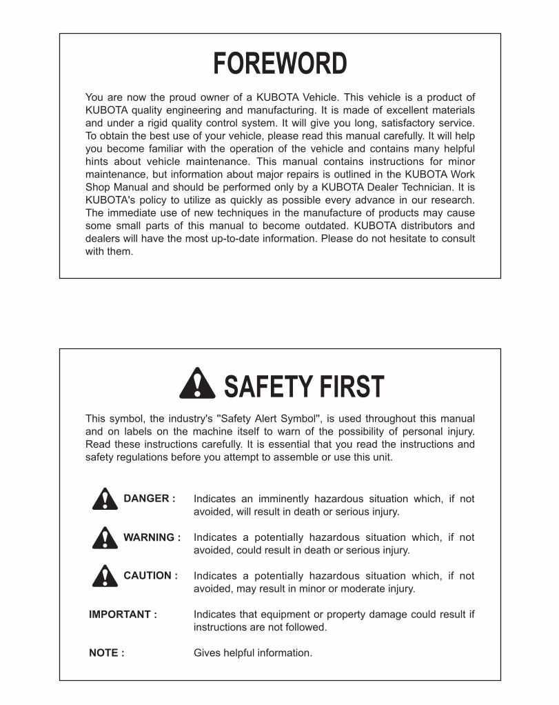
FOREWORD
3SAFETY FIRST
IMPORTANT :
NOTE :
3 DANGER :
3 WARNING :
3 CAUTION :
Indicates an imminently hazardous situation which, if not avoided, will result in death or serious injury.
Indicates a potentially hazardous situation which, if not avoided, could result in death or serious injury.
Indicates a potentially hazardous situation which, if not avoided, may result in minor or moderate injury.
Indicates that equipment or property damage could result if instructions are not followed.
Gives helpful information.
You are now the proud owner of a KUBOTA Vehicle. This vehicle is a product of KUBOTA quality engineering and manufacturing. It is made of excellent materials and under a rigid quality control system. It will give you long, satisfactory service. To obtain the best use of your vehicle, please read this manual carefully. It will help you become familiar with the operation of the vehicle and contains many helpful hints about vehicle maintenance. This manual contains instructions for minor maintenance, but information about major repairs is outlined in the KUBOTA Work Shop Manual and should be performed only by a KUBOTA Dealer Technician. It is KUBOTA's policy to utilize as quickly as possible every advance in our research. The immediate use of new techniques in the manufacture of products may cause some small parts of this manual to become outdated. KUBOTA distributors and dealers will have the most up-to-date information. Please do not hesitate to consult with them.
This symbol, the industry's ''Safety Alert Symbol'', is used throughout this manual and on labels on the machine itself to warn of the possibility of personal injury. Read these instructions carefully. It is essential that you read the instructions and safety regulations before you attempt to assemble or use this unit.
Downloaded from www.Manualslib.com manuals search engine

CONTENTSSAFE OPERATION ................................................................................................. 1
SERVICING OF VEHICLE........................................................................................... 1
SPECIFICATIONS....................................................................................................... 2SPECIFICATION TABLE ......................................................................................... 2TRAVELING SPEEDS ............................................................................................. 3
VEHICLE LIMITATIONS.............................................................................................. 4
INSTRUMENT PANEL AND CONTROLS................................................................... 5LOCATION OF PARTS............................................................................................ 5
PRE-OPERATION CHECK ......................................................................................... 9DAILY CHECK ......................................................................................................... 9
OPERATING THE ENGINE....................................................................................... 10STARTING THE ENGINE...................................................................................... 10
Cold Weather Starting ....................................................................................................12STOPPING THE ENGINE...................................................................................... 12WARMING UP ....................................................................................................... 12
Warm-Up Transmission Oil in the Low Temperature Range ..........................................12JUMP STARTING .................................................................................................. 13
OPERATING THE VEHICLE..................................................................................... 14OPERATING NEW VEHICLE ................................................................................ 14
Do not Operate the Vehicle at Full Speed for the First 50 Hours ...................................14Changing Lubricating Oil for New Vehicles ....................................................................14
STARTING............................................................................................................. 14Seat Belt .........................................................................................................................14Head Light Switch...........................................................................................................15Horn Button.....................................................................................................................15Brake Pedal ....................................................................................................................16Range Gear Shift Lever ..................................................................................................164WD Lever......................................................................................................................17Parking Brake Lever .......................................................................................................17Speed Control Pedal.......................................................................................................17
STOPPING............................................................................................................. 18Stopping..........................................................................................................................18
CHECK DURING DRIVING ................................................................................... 18Immediately Stop the Engine if: ......................................................................................18Easy Checker(TM)..........................................................................................................19Fuel Gauge.....................................................................................................................19Coolant Temperature Gauge..........................................................................................20Hourmeter.......................................................................................................................20
PARKING............................................................................................................... 20Parking Brake Lever .......................................................................................................20
ACCESSORY......................................................................................................... 2112V Electric Outlet ..........................................................................................................21
OPERATING TECHNIQUES ................................................................................. 21
Downloaded from www.Manualslib.com manuals search engine

CONTENTS
Differential Lock ..............................................................................................................21Unfamiliar Terrain ...........................................................................................................22Driving in Reverse ..........................................................................................................22Driving in "4WD" .............................................................................................................23Turning the Vehicle.........................................................................................................23Hills .................................................................................................................................24Traversing Hillsides ........................................................................................................24Sliding and Skidding .......................................................................................................24Driving through Water.....................................................................................................25
CARGO BED ............................................................................................................. 26CARGO BED.......................................................................................................... 26
General Caution..............................................................................................................26Max. Cargo Load ............................................................................................................26Cargo Bed Tailgate.........................................................................................................27Raising and Lowering the Cargo Bed.............................................................................28
TIRES AND WHEELS ............................................................................................... 29TIRES..................................................................................................................... 29
Inflation Pressure............................................................................................................29Tire Type and Use ..........................................................................................................29
WHEELS................................................................................................................ 30SHOCK ABSORBERS........................................................................................... 30
Rear Shock Absorber Spring Adjustment .......................................................................30
TOWING AND TRANSPORTING.............................................................................. 31TOWING AND TRANSPORTING .......................................................................... 31
Rear Trailer Hitch............................................................................................................31Front Trailer Hitch ...........................................................................................................31Winch Mount Bracket......................................................................................................32Transporting Vehicle.......................................................................................................32
MAINTENANCE......................................................................................................... 33SERVICE INTERVALS .......................................................................................... 33LUBRICANTS, FUEL AND COOLANT .................................................................. 36
PERIODIC SERVICE................................................................................................. 38HOW TO OPEN THE HOOD AND TILT THE SEAT.............................................. 38
Hood ...............................................................................................................................38Operator's Seat...............................................................................................................39
HOW TO RAISE THE CARGO BED...................................................................... 39Raising and Lowering the Cargo Bed.............................................................................39
JACK-UP POINT.................................................................................................... 40Front End........................................................................................................................40Rear End.........................................................................................................................40
DAILY CHECK ....................................................................................................... 41Walk Around Inspection..................................................................................................41Checking Amount of Fuel and Refueling ........................................................................41Checking Engine Oil Level..............................................................................................42Checking Transmission Fluid Level ................................................................................43Checking Coolant Level..................................................................................................43Cleaning Radiator Screen...............................................................................................44Checking Engine Cooling Fan ........................................................................................44
Downloaded from www.Manualslib.com manuals search engine
CONTENTS
Checking Brake Fluid Level ............................................................................................45Checking Brake Pedal ....................................................................................................45Checking Parking Brake .................................................................................................46Checking Gauges, Meter and Easy Checker(TM) ..........................................................46Checking Head Light, etc................................................................................................46Checking Seat Belt and ROPS.......................................................................................46Checking Joint Boot........................................................................................................46Checking Tire Inflation Pressure.....................................................................................47
EVERY 50 HOURS................................................................................................ 47Greasing .........................................................................................................................47Checking Engine Start System.......................................................................................49
EVERY 100 HOURS.............................................................................................. 49Checking VHT Neutral Spring.........................................................................................49Checking Wheel Bolt Torque..........................................................................................49Cleaning Air Cleaner Primary Element ...........................................................................50Cleaning Pre Cleaner Element .......................................................................................50Adjusting Alternator Drive Belt Tension ..........................................................................51Checking Fuel Line.........................................................................................................53Checking Battery Condition ............................................................................................54Adjusting Toe-in..............................................................................................................55Cleaning Spark Arrester .................................................................................................56
EVERY 200 HOURS.............................................................................................. 57Adjusting Parking Brake Lever .......................................................................................57Replacing Engine Oil Filter .............................................................................................57Changing Engine Oil.......................................................................................................58Cleaning Radiator Cooling Fins ......................................................................................59Replacing Transmission Oil Filter ...................................................................................60Checking Spark Plug Condition & Gap...........................................................................61Checking Brake Pedal ....................................................................................................62Checking Brake Hose and Pipe......................................................................................62Checking Brake Light Switch ..........................................................................................63Checking Radiator Hose and Clamp ..............................................................................63Checking Intake Air Line.................................................................................................64
EVERY 300 HOURS.............................................................................................. 64Checking Tire..................................................................................................................64
EVERY 400 HOURS.............................................................................................. 65Changing Transmission Oil.............................................................................................65Changing Front Axle Case Oil ........................................................................................66
EVERY 500 HOURS.............................................................................................. 66Adjusting Engine Valve Clearance .................................................................................66Checking Engine Timing Belt..........................................................................................66
EVERY 1000 HOURS............................................................................................ 66Replacing Engine Timing Belt.........................................................................................66
EVERY AFTER 1000 HOURS ............................................................................... 66Cleaning Engine Combustion Chamber .........................................................................66
EVERY 1 YEAR ..................................................................................................... 66Replacing Air Cleaner Primary Element and Secondary Element..................................66Replacing Pre Cleaner Element .....................................................................................66
EVERY 2 YEARS................................................................................................... 67Changing Brake Fluid .....................................................................................................67Flushing Cooling System and Changing Coolant ...........................................................67Anti-Freeze .....................................................................................................................67
Downloaded from www.Manualslib.com manuals search engine
CONTENTS
Replacing Radiator Hose (Water pipes) .........................................................................68Replacing Fuel Hose ......................................................................................................68Replacing Brake Master Cylinder (Inner Parts) ..............................................................68Replacing Intake Air Line................................................................................................68Replacing Engine Breather Hose ...................................................................................68
EVERY 4 YEARS................................................................................................... 69Replacing Brake Hose....................................................................................................69
SERVICE AS REQUIRED...................................................................................... 69Checking Brake Pad.......................................................................................................69Adjusting Parking Brake .................................................................................................69Adjusting Alternator Drive Belt Tension ..........................................................................69Replacing Fuse...............................................................................................................70Replacing Slow-Blow Fuses ...........................................................................................71Replacing Light Bulb.......................................................................................................71
STORAGE ................................................................................................................. 72VEHICLE STORAGE ............................................................................................. 72REMOVING THE VEHICLE FROM STORAGE..................................................... 72
TROUBLESHOOTING............................................................................................... 73ENGINE TROUBLESHOOTING ............................................................................ 73BATTERY TROUBLESHOOTING ......................................................................... 75MACHINE TROUBLESHOOTING ......................................................................... 76
OPTIONS................................................................................................................... 77
ENGINE EMISSION RELATED INFORMATION....................................................... 78
Downloaded from www.Manualslib.com manuals search engine

1SAFE OPERATION
SAFE OPERATIONCareful operation is your best insurance against anaccident.Read and understand this Operator's Manual carefullybefore operating the vehicle.All operators, no matter how much experience they mayhave, should read this and other related manuals beforeoperating the vehicle or any implement attached to it. It isthe owner's obligation to instruct all operators in safeoperation.
1. Know your equipment and its limitations. Read thisentire manual before attempting to start and operatethe vehicle.
2. Pay special attention to the Danger, Warning andCaution labels on the vehicle.
3. Do not remove Roll-Over Protective Structures(ROPS) for any application and fasten seat belts at alltimes. This combination will reduce the risk of seriousinjury or death, should the vehicle be upset.If the ROPS is loosened or removed for any reason,make sure that all parts are reinstalled correctly beforeoperating the vehicle.Never modify or repair a ROPS because welding,bending, drilling, grinding, or cutting may weaken thestructure.A damaged ROPS structure must be replaced, notrepaired or revised.If any structural member of the ROPS is damaged,replace the entire structure at your local KUBOTADealer.
4. Always use the seat belts. Check the seat beltsregularly and replace if frayed or damaged.
5. Do not operate the vehicle or any implement attachedto it while under the influence of alcohol, medication,controlled substances or while fatigued.
6. Carefully check the vicinity before operating thevehicle or any implement attached to it. Check foroverhead clearance which may interfere with the CABor ROPS. Do not allow any bystanders around or nearthe vehicle during operation.
7. Never allow anyone without a valid driver's license tooperate this vehicle.
8. Before allowing other people to use your vehicle,explain how to operate and have them read thismanual before operation.
9. Never wear loose, torn, or bulky clothing around thevehicle. It may catch on moving parts or controls,leading to the risk of an accident. Use additional safetyitems, e.g. helmet, safety boots or shoes, eye andhearing protection, gloves, etc., as appropriate orrequired.
10.This vehicle is for off road use only.KUBOTA does not recommend operating on publicroads.
11. In addition to the driver, only one passenger shouldride in the vehicle.Minimum age for passenger is 5 years old.
12.Keep all shields in place and stay away from allmoving parts.
13.Check brakes, speed control pedal, and othermechanical parts for improper adjustment and wear.Replace worn or damaged parts promptly. Check thetightness of all nuts and bolts regularly. (For furtherdetails, see "MAINTENANCE" section.)
14.Keep your vehicle clean. Dirt, grease, and trash buildup may contribute to fires and lead to personal injury.
15.Use only implements meeting the specifications listedunder "VEHICLE LIMITATIONS" in this manual orimplements approved by KUBOTA.
16.The maximum cargo capacity of this vehicle is 200kg.Reduce cargo capacity to match operating conditions.Do not carry anything which raises the center-of-gravity and sticks outside the cargo bed.
17.Do not modify the vehicle. Unauthorized modificationmay affect the function of the vehicle, which may resultin personal injury.
1. BEFORE OPERATING THE VEHICLE
(1) ROPS(2) Seat belt
Downloaded from www.Manualslib.com manuals search engine
SAFE OPERATION2
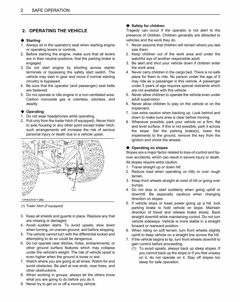
C Starting1. Always sit in the operator's seat when starting engine
or operating levers or controls.2. Before starting the engine, make sure that all levers
are in their neutral positions, that the parking brake isengaged.
3. Do not start engine by shorting across starterterminals or bypassing the safety start switch. Thevehicle may start in gear and move if normal startingcircuitry is bypassed.
4. Be sure that the operator (and passenger) seat beltsare fastened.
5. Do not operate or idle engine in a non-ventilated area.Carbon monoxide gas is colorless, odorless, anddeadly.
C Operating1. Do not wear headphones while operating.2. Pull only from the trailer hitch (if equipped). Never hitch
to axle housing or any other point except trailer hitch;such arrangements will increase the risk of seriouspersonal injury or death due to a vehicle upset.
3. Keep all shields and guards in place. Replace any thatare missing or damaged.
4. Avoid sudden starts. To avoid upsets, slow downwhen turning, on uneven ground, and before stopping.
5. The vehicle cannot turn with the differential locked andattempting to do so could be dangerous.
6. Do not operate near ditches, holes, embankments, orother ground surface features which may collapseunder the vehicle's weight. The risk of vehicle upset iseven higher when the ground is loose or wet.
7. Watch where you are going at all times. Watch for andavoid obstacles. Be alert at row ends, near trees, andother obstructions.
8. When working in groups, always let the others knowwhat you are going to do before you do it.
9. Never try to get on or off a moving vehicle.
C Safety for childrenTragedy can occur if the operator is not alert to thepresence of children. Children generally are attracted tovehicles and the work they do.1. Never assume that children will remain where you last
saw them.2. Keep children out of the work area and under the
watchful eye of another responsible adult.3. Be alert and shut your vehicle down if children enter
the work area.4. Never carry children in the cargo bed. There is no safe
place for them to ride. No person under the age of 5may ride as a passenger in this vehicle. A passengerunder 5 years of age requires special restraints whichare not available with this vehicle.
5. Never allow children to operate the vehicle even underadult supervision.
6. Never allow children to play on the vehicle or on theimplement.
7. Use extra caution when backing up. Look behind anddown to make sure area is clear before moving.
8. Whenever possible, park your vehicle on a firm, flatand level surface. If this is not possible, park it acrossthe slope. Set the parking brake(s), lower theimplements to the ground, remove the key from theignition and chock the wheels.
C Operating on slopesSlopes are a major factor related to loss-of-control and tip-over accidents, which can result in severe injury or death.All slopes require extra caution.1. Travel straight up or down hill.2. Reduce load when operating on hilly or over rough
terrain.3. Keep front wheels straight at crest of hill or going over
bumps.4. Do not stop or start suddenly when going uphill or
downhill. Be especially cautious when changingdirection on slopes.
5. If vehicle stops or loses power going up a hill, lockparking brake to hold vehicle on slope. Maintaindirection of travel and release brake slowly. Backstraight downhill while maintaining control. Do not turnvehicle sideways. Vehicle is more stable in a straightforward or rearward position.
6. When riding on soft terrain, turn front wheels slightlyuphill to keep vehicle on a straight line across the hill.
7. If the vehicle begins to tip, turn front wheels downhill togain control before proceeding.(1) To avoid upsets, always back up steep slopes. If
you cannot back up the slope or if you feel uneasyon it, do not operate on it. Stay off slopes toosteep for safe operation.
2. OPERATING THE VEHICLE
(1) Trailer hitch (if equipped)
Downloaded from www.Manualslib.com manuals search engine
3SAFE OPERATION
(2) Driving forward out of a ditch, mired condition orup a steep slope increases the risk of a vehicle tobe upset backward. Always back out of thesesituations. Extra caution is required with four-wheel drive mode because the increased tractioncan give the operator false confidence in thevehicle's ability to climb slopes.
(3) Keep all movement on slopes slow and gradual.Do not make sudden changes in speed ordirection.
C Operation in inclement conditions1. Only operate during daylight or with good artificial
light.2. Operate vehicle in an open, unobstructed area.3. Use helmet and/or protective gear for certain
operating conditions.4. Reduce speed according to trail, terrain and visibility
conditions.5. Never drive exceeding the limit of visibility. Slow down
near crest of hill until getting a clear view of the otherside.
6. Stay alert for holes, rocks and other hidden hazards inthe terrain.
7. Never cross any body of water where depth may beunknown to the operator (Deep water is consideredanything above the bottom edge of the axle cap).Choose a course within the waterway where bothbanks have a gradual incline. Cross at a point knownto be safe.
C Driving the vehicle at high speeds1. Check the front wheel engagement. The braking
characteristics are different between two and fourwheel drive. Be aware of the difference and usecarefully.
2. Always slow the vehicle down before turning. Turningat high speed may tip the vehicle over.
3. Turn the headlights on.4. Drive at speeds that allow you to maintain control at all
times.5. Do not apply the differential lock while traveling at high
speeds. The vehicle may run out of control.6. Avoid sudden motions of the steering wheel as they
can lead to a dangerous loss of stability. The risk isespecially great when the vehicle is traveling at highspeeds.
C Other miscellaneous1. Clean platform if dirty and remove any debris from
around foot controls.2. Always keep both hands on the steering wheel.3. Always keep arms and legs inside the operating
compartment.4. Never operate the vehicle while standing.5. Do not tow a cart with any riders on it.6. Never attempt wheelies, jumps or other stunts.
1. No riders in cargo bed or anywhere else.2. Do not overload vehicle. Securely anchor all loads.3. Be sure load is evenly distributed.4. Reduce cargo capacity when operating on rough or
hilly terrain.5. Balance loads evenly and secure them. Braking could
shift the load and affect vehicle stability.6. Never operate vehicle with the cargo bed raised.7. Operate cargo bed dump with vehicle stationary and
parking brake locked. Do not dump while moving.8. Operate the cargo bed dump on level ground only.9. Do not place hands or body under the cargo bed when
lowering bed.
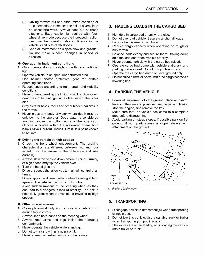
1. Lower all implements to the ground, place all controllevers in their neutral positions, set the parking brake,stop the engine, and remove the key.
2. Make sure that the vehicle has come to a completestop before dismounting.
3. Avoid parking on steep slopes, if possible park on flatground, if not, park across a slope, always withattachment on the ground.
1. Disengage power to attachment(s) when transportingor not in use.
2. Do not tow this vehicle. Use a suitable truck or trailerwhen transporting on public roads.
3. Use extra care when loading or unloading the vehicleinto a trailer or truck.
3. HAULING LOADS IN THE CARGO BED
4. PARKING THE VEHICLE
(1) Parking brake lever
5. TRANSPORTING
Downloaded from www.Manualslib.com manuals search engine

SAFE OPERATION4
Before servicing the vehicle, park it on a firm, flat and levelsurface, set the parking brake, lower all implements to theground, place the range gear shift lever in neutral, stop theengine and remove the key.1. Allow the vehicle time to cool off before working on or
near the engine, muffler, radiator, etc.2. Always stop the engine before refueling. Avoid spills
and overfilling.3. Do not smoke when working around battery or when
refueling. Keep all sparks and flames away frombattery and fuel tank. The battery presents anexplosive hazard, because it gives off hydrogen andoxygen especially when recharging.
4. Before "jump starting" a dead battery, read and followall of the instructions. (See "JUMP STARTING" in"OPERATING THE ENGINE" section.)
5. Keep first aid kit and fire extinguisher handy at alltimes.
6. Disconnect the battery's ground cable before workingon or near electric components.
7. To avoid the possibility of battery explosion, do not useor charge the refillable type battery if the fluid level isbelow the LOWER (lower limit level) mark. Check thefluid level regularly and add distilled water as requiredso that the fluid level is between the UPPER andLOWER marks.
8. To avoid sparks from an accidental short circuit,always disconnect the battery's ground cable (-) firstand reconnect it last.
9. Do not remove radiator cap while coolant is hot. Whencool, slowly rotate cap to the first stop and allowsufficient time for excess pressure to escape beforeremoving the cap completely. If the vehicle has acoolant recovery tank, add coolant or water to the tank,not the radiator. (See "Checking Coolant Level" in"DAILY CHECK" in "PERIODIC SERVICE" section.)
10.Do not attempt to mount a tire on a rim. This should bedone by a qualified person with the proper equipment.
11.Always maintain the correct tire pressure. Do notinflate tires above the recommended pressure shownin the operator's manual.
12.Securely support the vehicle when changing wheels.13.Make sure that wheel bolts have been tightened to the
specified torque.14.Do not work under any hydraulically supported
devices. They can settle, suddenly leak down, or beaccidentally lowered. If it is necessary to work underthe vehicle or any vehicle elements for servicing oradjustment, securely support them with stands orsuitable blocking beforehand.
15.Escaping hydraulic fluid under pressure has sufficientforce to penetrate skin causing serious personal injury.Before disconnecting hydraulic lines, be sure torelease all residual pressure. Before applyingpressure to the hydraulic system, make sure that allconnections are tight and that all lines, pipes, andhoses are free of damage."High pressure fluid - Injection into body" hazardwarning.
16.Fluid escaping from pinholes may be invisible. Do notuse hands to search for suspected leaks; use a pieceof cardboard or wood. Use of safety goggles or othereye protection is also highly recommended. If injuredby escaping fluid, see a medical doctor at once. Thisfluid will produce gangrene or severe allergic reaction.
6. SERVICING THE VEHICLE
(1) Battery
Downloaded from www.Manualslib.com manuals search engine

5SAFE OPERATION
(1) Cardboard(2) Hydraulic line(3) Magnifying glass
Downloaded from www.Manualslib.com manuals search engine
SAFE OPERATION6
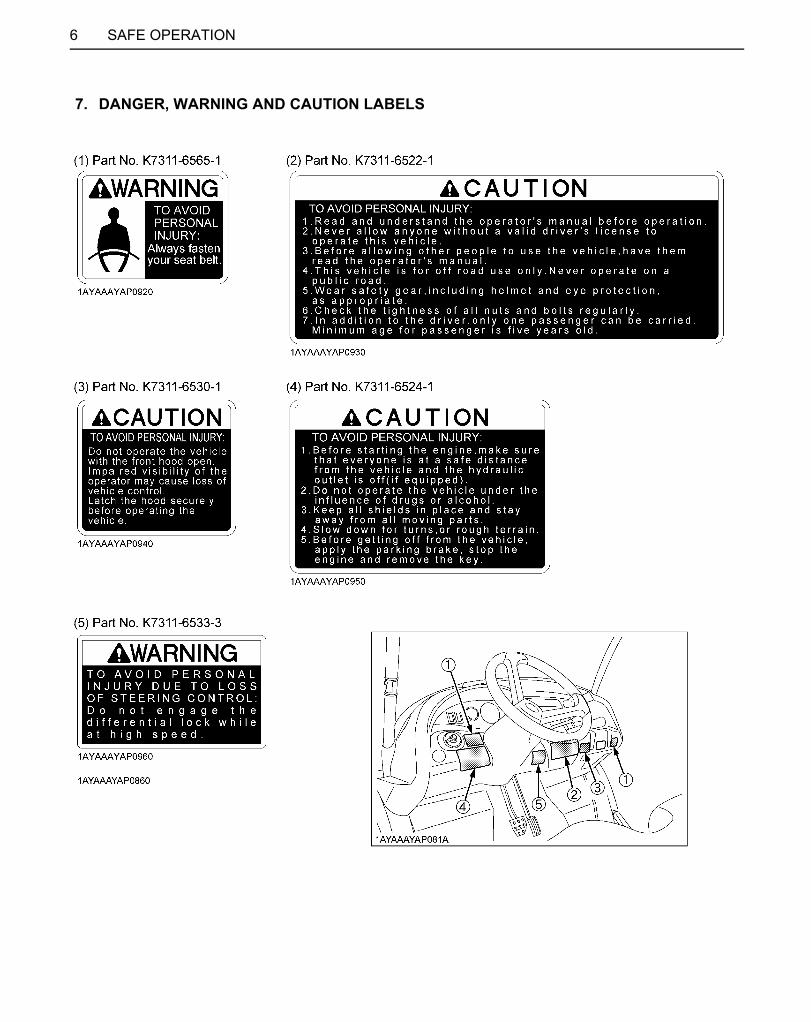
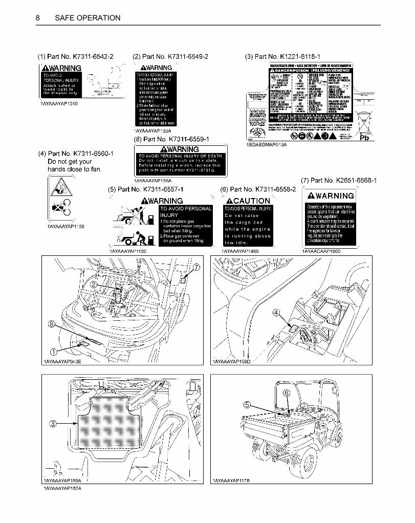
7. DANGER, WARNING AND CAUTION LABELS
Downloaded from www.Manualslib.com manuals search engine


9SAFE OPERATION
1. Keep danger, warning and caution labels clean and free from obstructing material.2. Clean danger, warning and caution labels with soap and water, dry with a soft cloth.3. Replace damaged or missing danger, warning and caution labels with new labels from your local KUBOTA Dealer.4. If a component with danger, warning and caution label(s) affixed is replaced with new part, make sure new label(s)
is(are) attached in the same location(s) as the replaced component.5. Mount new danger, warning and caution labels by applying on a clean dry surface and pressing any bubbles to outside
edge.
8. CARE OF DANGER, WARNING AND CAUTION LABELS
Downloaded from www.Manualslib.com manuals search engine


1SERVICING OF VEHICLE
SERVICING OF VEHICLEYour dealer is interested in your new vehicle and has thedesire to help you get the most value from it. After readingthis manual thoroughly, you will find that you can do someof the regular maintenance by yourself.However, when in need of parts or major service, be sureto see your KUBOTA Dealer.For service, contact the KUBOTA Dealership from whichyou purchased your vehicle or your local KUBOTADealer.When in need of parts, be prepared to give your dealervehicle, engine, transmission and ROPS serial numbers.Locate the serial numbers now and record them in thespace provided.
Type Serial No.
Vehicle
Engine
Transmission
ROPS
Product Identification Number
Date of Purchase
Name of Dealer(To be filled in by purchaser)
(1) Vehicle serial number(2) Vehicle identification number(3) ROPS serial number
(1) Engine serial number
(1) Transmission assy serial number
Downloaded from www.Manualslib.com manuals search engine
2 SPECIFICATIONS
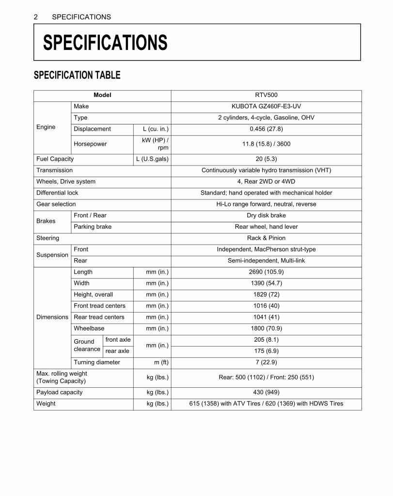
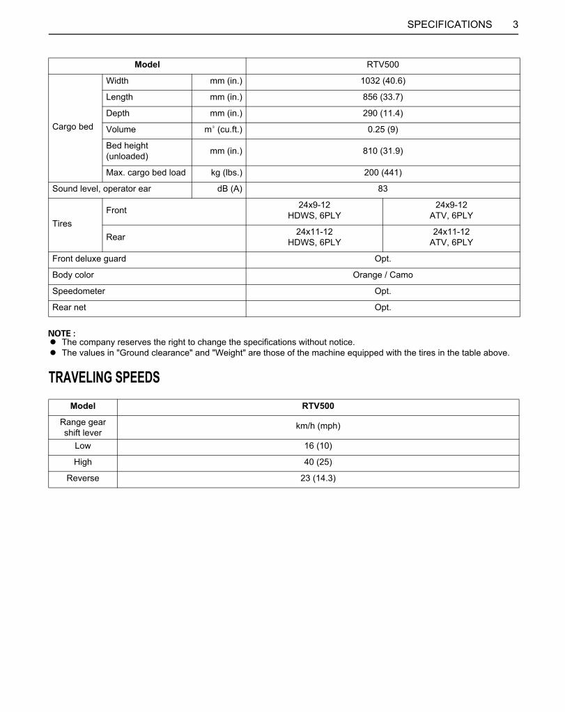
SPECIFICATIONSSPECIFICATION TABLE
Model RTV500
Engine
Make KUBOTA GZ460F-E3-UV
Type 2 cylinders, 4-cycle, Gasoline, OHV
Displacement L (cu. in.) 0.456 (27.8)
Horsepower kW (HP) /rpm 11.8 (15.8) / 3600
Fuel Capacity L (U.S.gals) 20 (5.3)
Transmission Continuously variable hydro transmission (VHT)
Wheels, Drive system 4, Rear 2WD or 4WD
Differential lock Standard; hand operated with mechanical holder
Gear selection Hi-Lo range forward, neutral, reverse
BrakesFront / Rear Dry disk brake
Parking brake Rear wheel, hand lever
Steering Rack & Pinion
SuspensionFront Independent, MacPherson strut-type
Rear Semi-independent, Multi-link
Dimensions
Length mm (in.) 2690 (105.9)
Width mm (in.) 1390 (54.7)
Height, overall mm (in.) 1829 (72)
Front tread centers mm (in.) 1016 (40)
Rear tread centers mm (in.) 1041 (41)
Wheelbase mm (in.) 1800 (70.9)
Ground clearance
front axlemm (in.)
205 (8.1)
rear axle 175 (6.9)
Turning diameter m (ft) 7 (22.9)
Max. rolling weight(Towing Capacity) kg (lbs.) Rear: 500 (1102) / Front: 250 (551)
Payload capacity kg (lbs.) 430 (949)
Weight kg (lbs.) 615 (1358) with ATV Tires / 620 (1369) with HDWS Tires
Downloaded from www.Manualslib.com manuals search engine
3SPECIFICATIONS
A The company reserves the right to change the specifications without notice.A The values in "Ground clearance" and "Weight" are those of the machine equipped with the tires in the table above.
TRAVELING SPEEDS
Cargo bed
Width mm (in.) 1032 (40.6)
Length mm (in.) 856 (33.7)
Depth mm (in.) 290 (11.4)
Volume m (cu.ft.) 0.25 (9)
Bed height(unloaded) mm (in.) 810 (31.9)
Max. cargo bed load kg (lbs.) 200 (441)
Sound level, operator ear dB (A) 83
TiresFront 24x9-12
HDWS, 6PLY24x9-12
ATV, 6PLY
Rear 24x11-12HDWS, 6PLY
24x11-12ATV, 6PLY
Front deluxe guard Opt.
Body color Orange / Camo
Speedometer Opt.
Rear net Opt.
Model RTV500
Range gearshift lever
km/h (mph)
Low 16 (10)
High 40 (25)
Reverse 23 (14.3)
Model RTV500
Downloaded from www.Manualslib.com manuals search engine

4 VEHICLE LIMITATIONS
VEHICLE LIMITATIONSThe KUBOTA Vehicle has been thoroughly tested for proper performance with implements sold or approved by KUBOTA.Use with implements which are not sold or approved by KUBOTA and which exceed the maximum specifications listedbelow, or which are otherwise unfit for use with the KUBOTA Vehicle may result in malfunctions or failures of the vehicle,damage to other property and injury to the operator or others. [Any malfunctions or failures of the vehicle resulting from usewith improper implements are not covered by the warranty]
A Above mentioned specifications are based on level ground condition.
Max. Cargo loading weight (W1) Rear trailer hitch Front trailer hitch
Max. Cargo load should not exceed "200 kg (441 lbs.)" or "CL".
CL = 453 kg (1000 lbs.) - (operator + passenger + opt. + acc. + cabin) weight
CL: Cargo Loadopt.: optionacc.: accessory
Max. rolling weight (W2)500 kg (1102 lbs.)
Max. rolling weight (W4)250 kg (551 lbs.)
Max. tongue weight (W3)50 kg (110 lbs.)
Max. tongue weight (W5)50 kg (110 lbs.)
Rolling weight: Trailer weight + Cargo Load
Downloaded from www.Manualslib.com manuals search engine

5INSTRUMENT PANEL AND CONTROLS
INSTRUMENT PANEL AND CONTROLSLOCATION OF PARTS
ILLUSTRATED CONTENTS
(1) ROPS............................................................. --
(2) Front hood...................................................... 38
(3) Headlights...................................................... 15
(4) Winch mount bracket...................................... 32
(5) Front trailer hitch bracket................................ 31
(6) Front trailer hitch (if equipped)........................ 31
Downloaded from www.Manualslib.com manuals search engine

6 INSTRUMENT PANEL AND CONTROLS
ILLUSTRATED CONTENTS
(1) Steering wheel................................................. --
(2) Hourmeter...................................................... 20
(3) Coolant temperature gauge............................ 20
(4) Horn button...................................................... 15
(5) Head light switch.............................................. 15
(6) Key switch........................................................ --
(7) Differential lock lever........................................ 21
(8) Easy Checker(TM)......................................... 19
(9) Range gear shift lever..................................... 16
(10) 4WD lever...................................................... 17
(11) Cup holder...................................................... --
(12) Glove box....................................................... --
(13) Operator's manual holder............................... --
(14) 12V accessory plug........................................ 21
(15) Speed control pedal....................................... 17
(16) Brake pedal.................................................... 16
Downloaded from www.Manualslib.com manuals search engine

7INSTRUMENT PANEL AND CONTROLS
ILLUSTRATED CONTENTS
(1) Seat belts....................................................... 14
(2) Seat............................................................... 39
(3) Parking brake lever........................................ 20
(4) Fuel gauge..................................................... 19
(5) Battery........................................................... --
Downloaded from www.Manualslib.com manuals search engine
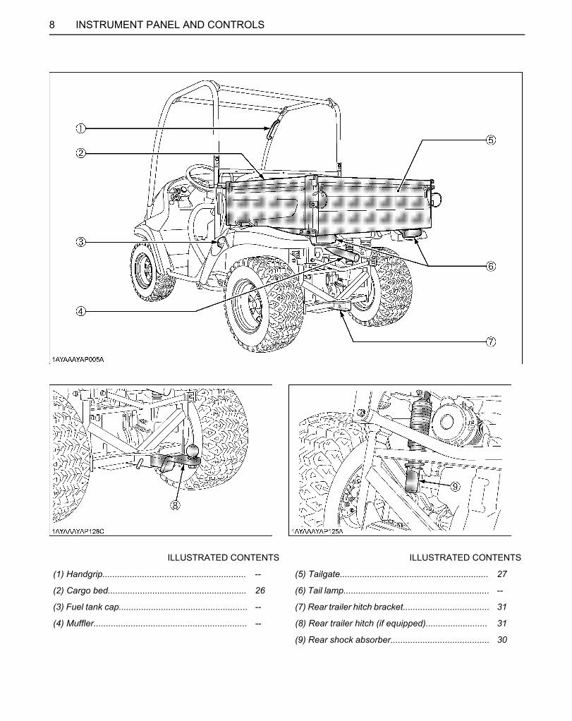
8 INSTRUMENT PANEL AND CONTROLS
ILLUSTRATED CONTENTS ILLUSTRATED CONTENTS
(1) Handgrip.......................................................... -- (5) Tailgate............................................................ 27
(2) Cargo bed........................................................ 26 (6) Tail lamp........................................................... --
(3) Fuel tank cap.................................................... -- (7) Rear trailer hitch bracket................................... 31
(4) Muffler.............................................................. -- (8) Rear trailer hitch (if equipped)......................... 31
(9) Rear shock absorber........................................ 30
Downloaded from www.Manualslib.com manuals search engine

9PRE-OPERATION CHECK
PRE-OPERATION CHECKDAILY CHECKTo prevent trouble from occurring, it is important to knowthe condition of the vehicle well. Check it before starting.
To avoid personal injury:A Be sure to check and service the vehicle on a
level surface with the engine shut off and theparking brake "ON" and implement lowered tothe ground if equipped.
Check item- Walk around inspection- Check engine oil level- Check transmission fluid level- Check brake fluid level- Check engine cooling fan [For those of the engine serial number 8U0086 or later, check the fan operation.]- Check coolant level- Clean radiator screen (When used in a dusty place)- Check brake- Check parking brake- Check indicators, gauges and meters- Check lights- Check seat belt and ROPS- Check front and drive joint boots- Check tire inflation pressure- Refuel (See "DAILY CHECK" in "PERIODIC SERVICE" section.)- Care of danger, warning and caution labels (See "DANGER, WARNING AND CAUTION LABELS" in "SAFE OPERATION" section.)
Downloaded from www.Manualslib.com manuals search engine

10 OPERATING THE ENGINE
OPERATING THE ENGINE
To avoid personal injury:A Read "SAFE OPERATION" in the front of this
manual.A Read the danger, warning and caution labels
located on the vehicle.A To avoid the danger of exhaust fume
poisoning, do not operate the engine in aclosed building without proper ventilation.
A Never start engine while standing on ground.Start engine only at the operator's seat.
A Make it a rule to set the range gear shift lever tothe "NEUTRAL" position.
A Do not use starting fluid to aid engine starting. A To protect the battery and the starter, make sure that
the starter is not continuously turned for more than 10seconds.If the engine dose not start, allow 60-second cooldown period between start attempts.
STARTING THE ENGINE
A The brake indicator light comes on while parking brakeis applied and goes off when it is released.
1. Make sure the parking brake is applied.
(1) Parking brake lever (A) Pull to "PARK"
(1) Brake indicator light
Downloaded from www.Manualslib.com manuals search engine

11OPERATING THE ENGINE
C Check Easy Checker(TM) Lamps:1. When the key is turned "ON", lamps(2)(3)(4) should
come on. If trouble should occur at any location whilethe engine is running, the warning lamp correspondingto that location comes on.
2. The brake indicator light(1) comes on.(1) While brake is applied and goes off when it is
released.(2) When the brake fluid is below the "MIN" mark.
(Add the brake fluid to the "MAX" mark.)(See "Checking Brake Fluid Level" in "DAILYCHECK" in "PERIODIC SERVICE" section.)
A Daily checks with the Easy Checker(TM) only, are notsufficient. Never fail to conduct daily checks carefullyby referring to "DAILY CHECK" in "PERIODICSERVICE" section.
A For further details of Easy Checker(TM), see "EasyChecker(TM)" in "CHECK DURING DRIVING" in"OPERATING THE VEHICLE" section.
A As safety function, the engine will not start unless therange gear shift lever is in the "NEUTRAL" position.
2. Set the range gear shift lever to the "NEUTRAL" position.
(1) Range gear shift lever (L) LOW Range(H) HIGH Range(N) "NEUTRAL" POSITION(R) "REVERSE"
3. Insert the key into the key switch and turn it "ON".
( ) "OFF" (Engine-Stop)( ) "ON" (Engine-Run)
( ) "START" (Engine-Start)
(1) Brake indicator light(2) Engine diagnostic light(3) Engine oil pressure light(4) Electrical charge light
4. Turn the key to the "START" position and release when the engine starts.
Downloaded from www.Manualslib.com manuals search engine

OPERATING THE ENGINE12
BCold Weather StartingWhen the ambient temperature is below 0 (32 ), theengine is very cold. If the engine fails to start after 10seconds, turn off the key for 30 seconds. Then repeatsteps 3 and 4. To protect the battery and the starter, makesure that the starter is not continuously turned for morethan 10 seconds.
STOPPING THE ENGINE1. After slowing the engine to idle, turn the key to "OFF".2. Remove the key.
WARMING UP
To avoid personal injury:A Be sure to set the parking brake during warm-
up.A Be sure to set the range shift lever to the
"NEUTRAL" position.
For 5 minutes after engine start-up, allow the engine towarm up without applying any load. This is to allow oil toreach every engine part. If load should be applied to theengine without this warm-up period, trouble such asseizure, breakage or premature wear may develop.
BWarm-Up Transmission Oil in the Low Temperature Range
Hydraulic oil serves as transmission fluid. In cold weather,the oil may be cold with increased viscosity. This cancause delayed oil circulation or abnormally low hydraulicpressure for some time after engine start-up. This in turncan result in trouble in the hydraulic system.To prevent the above, observe the following instructions:Warm up the engine at about 50% of rated rpm accordingto the table below:
A Do not operate the vehicle under full load conditionuntil it is sufficiently warmed up.
Ambient temperature Warm-up time requirement
Above 0 (32 ) Approx. 5 minutes
-10 to 0 (14 to 32 ) 5 to 10 minutes
-20 to -10 (-4 to 14 ) 10 to 15 minutes
Below -20 (-4 ) More than 15 minutes
Downloaded from www.Manualslib.com manuals search engine

13OPERATING THE ENGINE
JUMP STARTING
To avoid personal injury:A Battery gases can explode. Keep cigarettes,
sparks, and flames away from battery.A If vehicle battery is frozen, do not jump start
engine.A Do not connect other end of negative jumper
cable to negative terminal of vehicle battery.A The parts such as the muffler may be hot. Be
careful not to get burned in connecting jumpercables.
When jump starting engine, follow the instructions belowto safely start the engine.1. Bring helper vehicle with a battery of the same voltage
as disabled vehicle within easy cable reach. "THEVEHICLES MUST NOT TOUCH".
2. Engage the parking brake of both vehicles and put theshift lever in neutral. Shut the engine off.
3. Put on safety goggles and rubber gloves.4. Ensure the vent caps are securely in place. (if
equipped)5. Cover vent holes with damp rags. Do not allow the rag
to touch the battery terminals.6. Attach the red clamp to the positive (red, (+) or pos.)
terminal of the dead battery and clamp the other endof the same cable to the positive (red, (+) or pos.)terminal of the helper battery.
7. Clamp the other cable to the negative (black, (-) orneg.) terminal of the helper battery.
8. Clamp the other end to the engine block or frame ofthe disabled vehicle as far from the dead battery aspossible.
9. Start the helper vehicle and let its engine run for a fewmoments. Start the disabled vehicle.
10.Disconnect the jumper cables in the exact reverseorder of attachment. (Steps 8, 7 and 6).
11.Remove and discard the damp rags.
A This vehicle has a 12 volt negative (-) ground startingsystem.
A Use only same voltage for jump starting.A Use of a higher voltage source could result in severe
damage to vehicle's electrical system.Use only matching voltage source when "Jumpstarting" a low or dead battery.
(1) Dead battery(2) Lay a damp rag over the vent caps(3) Jumper cables(4) Helper battery
Downloaded from www.Manualslib.com manuals search engine
14 OPERATING THE VEHICLE
OPERATING THE VEHICLEOPERATING NEW VEHICLEHow a new vehicle is handled and maintained determinesthe life of the vehicle.A new vehicle just off the factory production line has been,of course, tested, but the various parts are notaccustomed to each other, so care should be taken tooperate the vehicle for the first 50 hours at a slower speedand avoid excessive work or operation until the variousparts become "broken-in." The manner in which thevehicle is handled during the "breaking-in" period greatlyaffects the life of your vehicle. Therefore, to obtain themaximum performance and the longest life of the vehicle,it is very important to properly break-in your vehicle. Inhandling a new vehicle, the following precautions shouldbe observed.
BDo not Operate the Vehicle at Full Speed for the First 50 Hours
A Do not start quickly nor apply the brakes suddenly.A In winter, operate the vehicle after fully warming up the
engine.A Do not run the engine at speeds faster than
necessary.A On rough roads, slow down to suitable speeds.
Do not operate the vehicle at fast speed. The aboveprecautions are not limited only to new vehicles, but toall vehicles. But it should be especially observed in thecase of new vehicles.
BChanging Lubricating Oil for New Vehicles
The lubricating oil is especially important in the case of anew vehicle. The various parts are not "broken-in" and arenot accustomed to each other. Small pieces of metal gritmay develop during the operation of the vehicle; and thismay wear out or damage the parts. Therefore, care shouldbe taken to change the lubricating oil a little earlier thanwould ordinarily be required. For further details of changeinterval hours, see "MAINTENANCE" section.
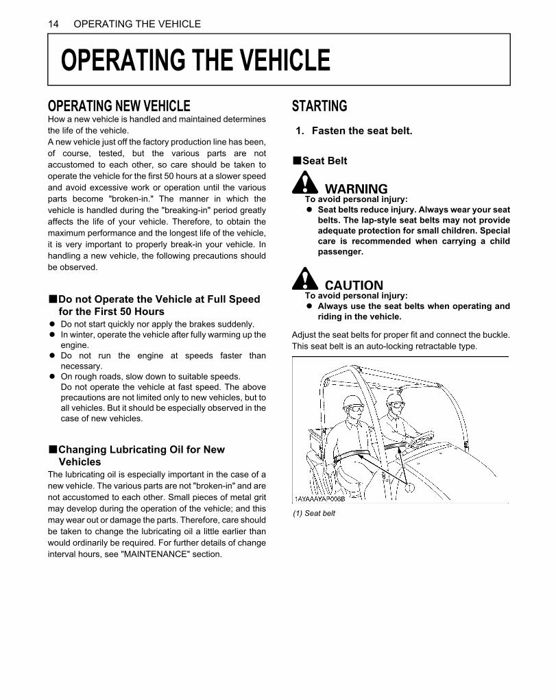
STARTING
BSeat Belt
To avoid personal injury:A Seat belts reduce injury. Always wear your seat
belts. The lap-style seat belts may not provideadequate protection for small children. Specialcare is recommended when carrying a childpassenger.
To avoid personal injury:A Always use the seat belts when operating and
riding in the vehicle.
Adjust the seat belts for proper fit and connect the buckle.This seat belt is an auto-locking retractable type.
1. Fasten the seat belt.
(1) Seat belt
Downloaded from www.Manualslib.com manuals search engine

15OPERATING THE VEHICLE
BHead Light SwitchThe head light switch is operative when the key switch isin the "ON" position.Turn on the key switch and turn the head light switch tothe "ON" position.Turn the head light switch to the "OFF" position to turn offthe head light.
A Turning the head light switch to the "ON" positioncauses the following lamps to light simultaneously.(1) Tail lights (lamps at the rear portions of the
vehicle)(2) Lamp built in the coolant temperature gauge
BHorn ButtonThe horn switch is operative when the key switch is ineither the "ON" or "OFF" position.The horn will sound when the horn button is pressed.
2. Selecting light switch position.
(1) Head light switch Head lights "ON" Head lights "OFF"
(1) Horn button
Downloaded from www.Manualslib.com manuals search engine

OPERATING THE VEHICLE16
BBrake Pedal
To avoid personal injury:A If the operator suddenly brakes, an accident
may occur due to loss of control or the shiftingforward of heavy loads.
A When driving on icy, wet or loose surface,make sure the vehicle is correctly ballasted toavoid skidding and loss of steering control.Operate at reduced speed.
The brake pedal is the left pedal on the foot board.Depress the pedal to slow or stop the vehicle.
BRange Gear Shift Lever
To avoid personal injury:A Avoid changing range gear shift lever when
ascending or descending a slope.A Before ascending or descending a slope, shift
to the "L" range to control the vehicle speed.A If you shift gears while ascending or
descending a slope, be prepared to use thebrake to maintain control.
A Operate in reverse at slow speeds to maintaincontrol.
1. The range gear shift lever can only be shifted whenvehicle is completely stopped and the speed controlpedal is in the "NEUTRAL" position.
2. To avoid transmission and shift linkage damage,completely stop the vehicle using the brake pedalbefore shifting gears.
3. Select proper gear and engine speed depending onthe type of job.
4. Before dismounting vehicle, shift the range gear shiftlever to the "NEUTRAL" position and apply parkingbrake.
3. Checking the brake pedal.
(1) Brake pedal
4. Selecting the travel speed.
(1) Range gear shift lever (L) LOW Range(H) HIGH Range(N) "NEUTRAL" POSITION(R) "REVERSE"
Downloaded from www.Manualslib.com manuals search engine

17OPERATING THE VEHICLE
A Do not force the range gear shift lever. If it is difficult toshift the lever into "L", or "H" on slopes, be sure toapply the parking brake before starting the procedure.(1) Slightly depress the speed control pedal to rotate
the gears inside of transmission.(2) Release the speed control pedal to the
"NEUTRAL" position.A An accident may occur with erratic shifting operation.A Improper range gear shift lever position will cause the
vehicle to momentarily coast on slopes.
B4WD Lever
To avoid personal injury:A Do not engage the front wheel drive when
traveling at road speed.A When driving on icy, wet or loose surfaces,
make sure the vehicle is correctly ballasted toavoid skidding and loss of steering control.Operate at reduced speed and engage frontwheel drive.
A An accident may occur if the vehicle issuddenly braked, such as by heavy towedloads shifting forward causing loss of control.
A The braking characteristics are differentbetween two and four wheel drive. Be aware ofthe difference and use carefully.
A Use the lever to engage the front wheels with thevehicle stopped. Shift the lever to "4WD" to engage thefront wheel drive.
A Tires will wear quickly if front wheel drive is engagedon paved roads.
A If the 4WD lever is difficult to shift to "2WD", stop thevehicle, turn the steering wheel in both directions andthen move the lever.
C Front wheel drive is effective for the followingjobs:
1. When greater pulling force is needed, such as workingin a wet field, when pulling a trailer, or when workingwith a front-end blade.
2. When working in sandy soil.
BParking Brake LeverTo release the parking brake, depress the brake pedal,push release button and push down parking brake lever.Make sure that indicator in the Easy Checker(TM) goesoff.
BSpeed Control PedalUse the speed control pedal when traveling. Push downon it for higher speed.
(1) 4WD lever "4WD" "2WD"
5. Unlock the parking brake and start slowly.
(1) Parking brake lever(2) Release button
(A) "RELEASE"
(1) Speed control pedal
Downloaded from www.Manualslib.com manuals search engine
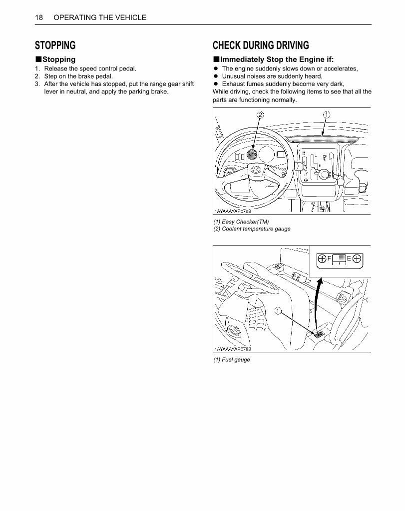
OPERATING THE VEHICLE18
STOPPINGBStopping1. Release the speed control pedal.2. Step on the brake pedal.3. After the vehicle has stopped, put the range gear shift
lever in neutral, and apply the parking brake.
CHECK DURING DRIVINGBImmediately Stop the Engine if:A The engine suddenly slows down or accelerates,A Unusual noises are suddenly heard,A Exhaust fumes suddenly become very dark,While driving, check the following items to see that all theparts are functioning normally.
(1) Easy Checker(TM)(2) Coolant temperature gauge
(1) Fuel gauge
Downloaded from www.Manualslib.com manuals search engine
19OPERATING THE VEHICLE
BEasy Checker(TM)If the warning lamps in the Easy Checker(TM) come onduring operation, immediately stop the engine, and findthe cause as shown below.Never operate the vehicle with an Easy Checker(TM)lamp on.
( ) Brake indication lightThe warning lamp in the Easy Checker(TM) comes onif the parking brake is applied.If the lamp is on during operation, release the parkingbrake lever immediately.If the brake fluid goes below the prescribed level, thewarning lamp in the Easy Checker(TM) will come on.If this should happen during operation, check to seethat there is no oil leak in the brake system, and thenadd oil.(See "Checking Brake Fluid Level" in "DAILY CHECK"in "PERIODIC SERVICE" section.)
Engine diagnostic lightIf sensors malfunction, the Easy Checker(TM) willcome on. If the light is active, stop the vehicle and shutoff the engine. If the light is active after restart, consultyour local KUBOTA Dealer.
Engine oil pressure lightIf the oil pressure in the engine goes below theprescribed level, the warning lamp in the EasyChecker(TM) will come on.If this should happen during operation, and it does notgo off when the engine is accelerated, check the levelof engine oil.(See "Checking Engine Oil Level" in "DAILY CHECK"in "PERIODIC SERVICE" section.)
Electrical charge lightIf the alternator is not charging the battery, the EasyChecker(TM) will come on.If this should happen during operation, check theelectrical charging system or consult your localKUBOTA Dealer.
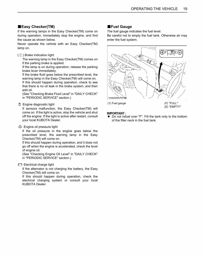
BFuel GaugeThe fuel gauge indicates the fuel level.Be careful not to empty the fuel tank. Otherwise air mayenter the fuel system.
A Do not refuel over "F". Fill the tank only to the bottomof the filler neck in the fuel tank.
(1) Fuel gauge (F) "FULL"(E) "EMPTY"
Downloaded from www.Manualslib.com manuals search engine

OPERATING THE VEHICLE20
BCoolant Temperature Gauge
To avoid personal injury:A Do not remove radiator cap until coolant
temperature is well below its boiling point.Then loosen cap slightly to the stop to relieveany pressure before removing cap completely.
1. With the key switch "ON" the temperature gaugeindicates the temperature of the coolant. White Zonefor "COLD" and Red zone for "HOT".
2. If the indicator reaches the Red zone, engine coolantis overheated. Check the vehicle by referring to"TROUBLESHOOTING" section.
BHourmeterThe hourmeter indicates in 5 digits the hours the vehiclehas been used; the last digit indicates 1/10 of an hour.
PARKINGBParking Brake Lever
To avoid personal injury:BEFORE DISMOUNTING VEHICLE A ALWAYS APPLY THE PARKING BRAKE AND
LOWER ALL IMPLEMENTS TO THE GROUND.Leaving transmission in gear with the enginestopped will not prevent from rolling.
A STOP THE ENGINE AND REMOVE THE KEY.
1. Stop the vehicle on a level surface.2. To apply the parking brake, depress the brake pedal
and pull the parking brake lever to park.3. To release the parking brake, push the release button
and push down the parking brake lever. When theparking brake is released, the brake indicator light inthe Easy Checker(TM) goes off.
A If the vehicle is operated with the parking brakeapplied, the parking brake will be damaged.
(1) Coolant temperature gauge
(1) Hourmeter
(1) Parking brake lever(2) Release button
(A) "RELEASE"
Downloaded from www.Manualslib.com manuals search engine
21OPERATING THE VEHICLE
ACCESSORYB12V Electric OutletThe 12 volt receptacle is located on the front-panel. Anauxiliary light or other devices may be connected to thisconnector.
C This outlet is activated when the key switch is ineither the "ON" or "OFF" position.
When the plug is not used, pull it out. Be careful thatleaving the plug inserted causes the battery to run out.
C Do not connect a light or other device that drawsmore than 120 watts to this connector, or thebattery may discharge very rapidly or the outletmay fail.
A Do not use as a cigarette lighter.A Do not use when wet.
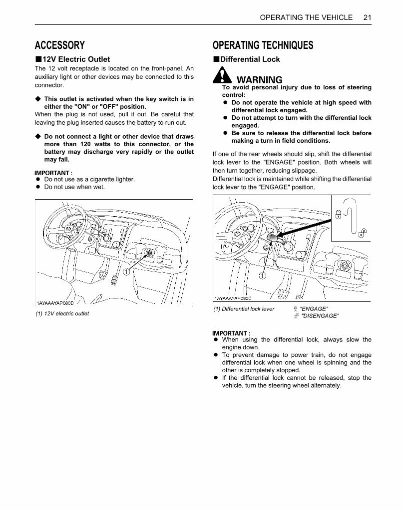
OPERATING TECHNIQUESBDifferential Lock
To avoid personal injury due to loss of steeringcontrol:A Do not operate the vehicle at high speed with
differential lock engaged.A Do not attempt to turn with the differential lock
engaged.A Be sure to release the differential lock before
making a turn in field conditions.
If one of the rear wheels should slip, shift the differentiallock lever to the "ENGAGE" position. Both wheels willthen turn together, reducing slippage.Differential lock is maintained while shifting the differentiallock lever to the "ENGAGE" position.
A When using the differential lock, always slow theengine down.
A To prevent damage to power train, do not engagedifferential lock when one wheel is spinning and theother is completely stopped.
A If the differential lock cannot be released, stop thevehicle, turn the steering wheel alternately.
(1) 12V electric outlet(1) Differential lock lever "ENGAGE"
"DISENGAGE"
Downloaded from www.Manualslib.com manuals search engine

OPERATING THE VEHICLE22
BUnfamiliar Terrain
To avoid personal injury:A Be sure to check for hidden obstacles or
hazards before driving in a new area.A Keep your speed down until you know the area
well.A Use existing trails and stay away from
hazardous areas such as steep, rocky slopesor swamps.
A Be cautious when visibility is limited, as youmay not be able to see obstacles in your path.
BDriving in Reverse
To avoid personal injury:A Turn around, look down and behind you before
backing up to be sure there are no obstacles orpeople in your way.
A Depress speed control pedal gradually andback up cautiously.
A To stop while driving in reverse take your footoff the speed control pedal and gradually applythe brake.
A Do not suddenly engage the brake.
Downloaded from www.Manualslib.com manuals search engine

23OPERATING THE VEHICLE
BDriving in "4WD"
To avoid personal injury:A Do not drive in "4WD" on paved surfaces.
For the maximum traction, shift the range gear shift leverinto low range and use "4WD" on steep slopes or whenstuck in the mud, with differential locked if necessary.
BTurning the Vehicle
To avoid personal injury:A Reduce vehicle speed before entering the turn
and maintain an even speed through the turn.A Do not make sharp turns in order to avoid loss
of control or tipping.
Downloaded from www.Manualslib.com manuals search engine
OPERATING THE VEHICLE24
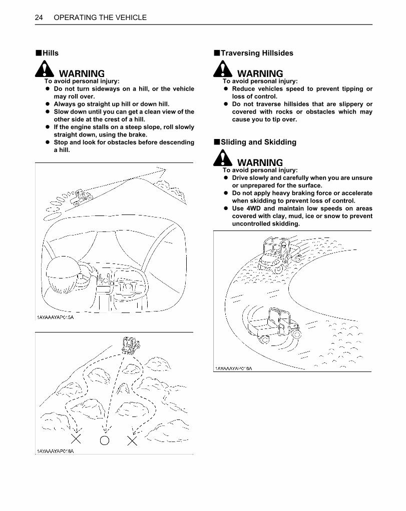
BHills
To avoid personal injury:A Do not turn sideways on a hill, or the vehicle
may roll over.A Always go straight up hill or down hill.A Slow down until you can get a clean view of the
other side at the crest of a hill.A If the engine stalls on a steep slope, roll slowly
straight down, using the brake.A Stop and look for obstacles before descending
a hill.
BTraversing Hillsides
To avoid personal injury:A Reduce vehicles speed to prevent tipping or
loss of control.A Do not traverse hillsides that are slippery or
covered with rocks or obstacles which maycause you to tip over.
BSliding and Skidding
To avoid personal injury:A Drive slowly and carefully when you are unsure
or unprepared for the surface.A Do not apply heavy braking force or accelerate
when skidding to prevent loss of control.A Use 4WD and maintain low speeds on areas
covered with clay, mud, ice or snow to preventuncontrolled skidding.
Downloaded from www.Manualslib.com manuals search engine
25OPERATING THE VEHICLE
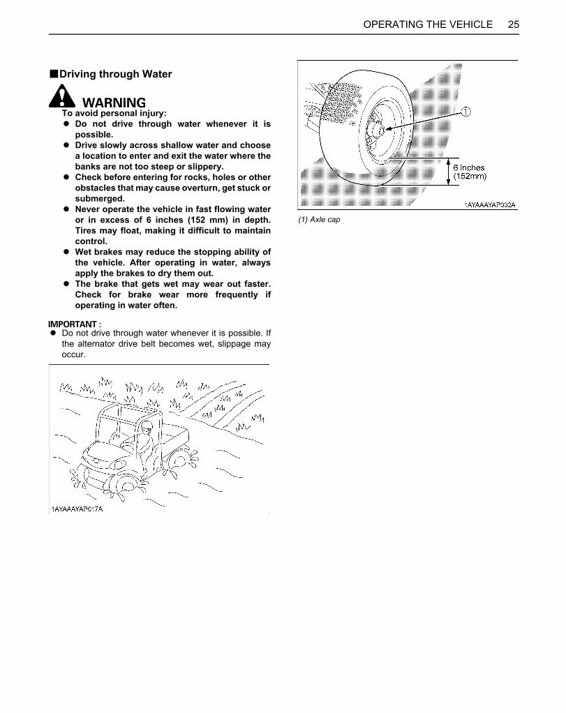
BDriving through Water
To avoid personal injury:A Do not drive through water whenever it is
possible.A Drive slowly across shallow water and choose
a location to enter and exit the water where thebanks are not too steep or slippery.
A Check before entering for rocks, holes or otherobstacles that may cause overturn, get stuck orsubmerged.
A Never operate the vehicle in fast flowing wateror in excess of 6 inches (152 mm) in depth.Tires may float, making it difficult to maintaincontrol.
A Wet brakes may reduce the stopping ability ofthe vehicle. After operating in water, alwaysapply the brakes to dry them out.
A The brake that gets wet may wear out faster.Check for brake wear more frequently ifoperating in water often.
A Do not drive through water whenever it is possible. Ifthe alternator drive belt becomes wet, slippage mayoccur.
(1) Axle cap
Downloaded from www.Manualslib.com manuals search engine
26 CARGO BED
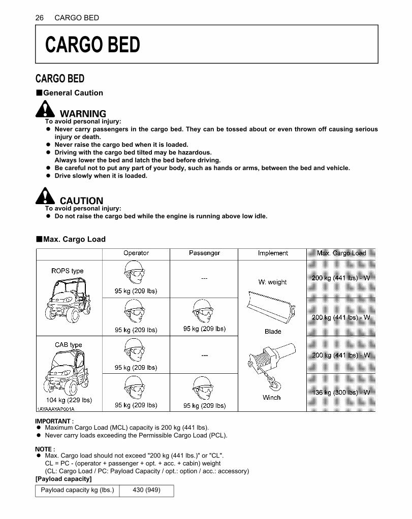
CARGO BEDCARGO BEDBGeneral Caution
To avoid personal injury:A Never carry passengers in the cargo bed. They can be tossed about or even thrown off causing serious
injury or death.A Never raise the cargo bed when it is loaded.A Driving with the cargo bed tilted may be hazardous.
Always lower the bed and latch the bed before driving.A Be careful not to put any part of your body, such as hands or arms, between the bed and vehicle.A Drive slowly when it is loaded.
To avoid personal injury:A Do not raise the cargo bed while the engine is running above low idle.
BMax. Cargo Load
A Maximum Cargo Load (MCL) capacity is 200 kg (441 lbs).A Never carry loads exceeding the Permissible Cargo Load (PCL).
A Max. Cargo load should not exceed "200 kg (441 lbs.)" or "CL".CL = PC - (operator + passenger + opt. + acc. + cabin) weight(CL: Cargo Load / PC: Payload Capacity / opt.: option / acc.: accessory)
[Payload capacity]Payload capacity kg (lbs.) 430 (949)
Downloaded from www.Manualslib.com manuals search engine

27CARGO BED
BCargo Bed Tailgate
To avoid personal injury:A Do not apply a load to the tailgate while the
tailgate is open, or the wire loop may break.A Do not place fingers or hands between the
tailgate and the arm (latch) when closing, orfingers or hands may be pinched.
For loading and unloading, the tailgate of the cargo bedcan be opened.The tailgate is held level to the cargo bed floor with wireloops.Do not move the vehicle with the tailgate fully lowered.In a fully lowered position, the tailgate may obstruct thevehicle tail lamps and damage them by swinging motion.
1. Raise the arms (latch) at each end of the tailgate andopen the tailgate.
2. Close the tailgate by lifting it and pushing it firmlyclosed. Push the arms (latch) down to make sure thelatches stay securely closed.
A TO AVOID TAILGATE DAMAGE:Remove the rear trailer hitch when wire loop isremoved and cargo bed is raised.
(1) Tailgate(2) Arm (latch)(3) Wire loop
Downloaded from www.Manualslib.com manuals search engine
CARGO BED28
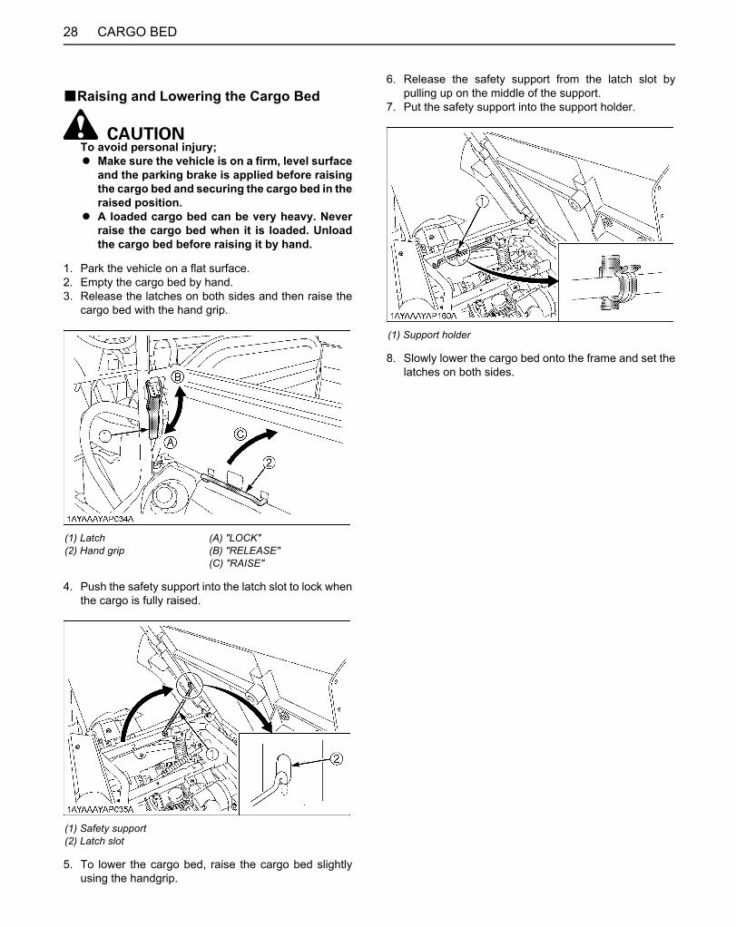
BRaising and Lowering the Cargo Bed
To avoid personal injury;A Make sure the vehicle is on a firm, level surface
and the parking brake is applied before raisingthe cargo bed and securing the cargo bed in theraised position.
A A loaded cargo bed can be very heavy. Neverraise the cargo bed when it is loaded. Unloadthe cargo bed before raising it by hand.
1. Park the vehicle on a flat surface.2. Empty the cargo bed by hand.3. Release the latches on both sides and then raise the
cargo bed with the hand grip.
4. Push the safety support into the latch slot to lock whenthe cargo is fully raised.
5. To lower the cargo bed, raise the cargo bed slightlyusing the handgrip.
6. Release the safety support from the latch slot bypulling up on the middle of the support.
7. Put the safety support into the support holder.
8. Slowly lower the cargo bed onto the frame and set thelatches on both sides.
(1) Latch(2) Hand grip
(A) "LOCK"(B) "RELEASE"(C) "RAISE"
(1) Safety support(2) Latch slot
(1) Support holder
Downloaded from www.Manualslib.com manuals search engine

29TIRES AND WHEELS
TIRES AND WHEELSTIRES
To avoid personal injury:A Do not attempt to mount a tire on a rim. This
should be done by a qualified person with theproper equipment.
A Always maintain the correct tire pressure.Do not inflate tires above the recommendedpressure shown in the operator's manual.
A Do not use tires other than those approved byKUBOTA.
BInflation PressureThough the tire pressure is factory-set to the prescribedlevel, it naturally drops slowly in the course of time. Thus,check it everyday and inflate as necessary.
BTire Type and UseC Heavy duty work site tire
C All terrain vehicle tire
Tire sizes Inflation Pressure
24 x 9 - 12 HDWS,Front
24 x 11 - 12 HDWS,Rear 97 kPa
(0.97 kgf/cm , 14 psi)24 x 9 - 12 ATV,Front
24 x 11 - 12 ATV,Rear
(1) Ground (A) "INSUFFICIENT"(B) "NORMAL"(C) "EXCESSIVE"
Downloaded from www.Manualslib.com manuals search engine

TIRES AND WHEELS30
WHEELS
To avoid personal injury:A Support vehicle securely on stands before
removing a wheel.A Never operate vehicle with loose wheel bolts.
A When re-fitting a wheel, tighten the bolts to thefollowing torques then recheck after driving the vehicle200 m (200 yards) and thereafter according to serviceinterval.
SHOCK ABSORBERSBRear Shock Absorber Spring Adjustment
To avoid personal injury:A Be sure to work on a firm, flat and level surface
with the engine shut off and parking brake"ON".
A Keep the position of the left and right rearshock absorber equal.Uneven adjustment can cause poor handlingand loss of control, which could lead to anaccident.
The spring adjusting sleeves on the rear shock absorbershave 5 positions so that the springs can be adjusted fordifferent riding and loading conditions.For adjusting the rear shock absorber springs, turn theadjusting sleeves on the shock absorbers to the desiredposition with the hook wrench.
[Rear shock absorber position]
A If you feel any difficulty in the adjustment, consult yourlocal KUBOTA dealer.
The rear shock absorber spring is adjusted to thirdposition (default) in the figure below.
(1) Torque wheel bolts to 108.4 to 121.9 N-m (11 to 12.4 kgf-m) (80 to 90 ft-lbs.)
Position Spring Feeling Load
1 Stronger Hard Heavy
2
3 (default)
4
5 Weaker Soft Light
(A) Rear shock absorber(B) Adjusting sleeve (Turn here with a hook wrench.)
Downloaded from www.Manualslib.com manuals search engine

31TOWING AND TRANSPORTING
TOWING AND TRANSPORTINGTOWING AND TRANSPORTINGBRear Trailer Hitch[if equipped]
To avoid personal injury:A Always tow a load slowly enough to maintain
control and avoid tipping.A To provide adequate braking ability and
traction, do not tow a load unless vehicle cargobed is loaded or attachment is installed.
A Attach a trailer to the trailer hitch only.
The rear trailer hitch load is listed in the "VEHICLELIMITATIONS" section. When towing other equipment,use a safety chain.
BFront Trailer Hitch[if equipped]
To avoid personal injury:A Do not tow this vehicle unless all the functions
of the vehicle are properly working, since themalfunction of steering operation or brakingmay cause an accident.
Use the front trailer hitch for greater maneuverability inconfined areas such as a barn.The front trailer hitch load is listed in the "VEHICLELIMITATIONS" section.
(1) Rear trailer hitch (if equipped)(2) Hitch pin (if equipped)
(1) Front trailer hitch (if equipped)(2) Hitch pin (if equipped)
Downloaded from www.Manualslib.com manuals search engine
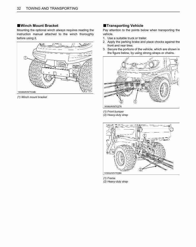
TOWING AND TRANSPORTING32
BWinch Mount BracketMounting the optional winch always requires reading theinstruction manual attached to the winch thoroughlybefore using it.
BTransporting VehiclePay attention to the points below when transporting thevehicle.1. Use a suitable truck or trailer.2. Apply the parking brake and place chocks against the
front and rear tires.3. Secure the portions of the vehicle, which are shown in
the figure below, by using strong straps or chains.
(1) Winch mount bracket
(1) Front bumper(2) Heavy-duty strap
(1) Frame(2) Heavy-duty strap
Downloaded from www.Manualslib.com manuals search engine

33MAINTENANCE
MAINTENANCE
To avoid personal injury and vehicle damage:A Be sure you have sufficient knowledge, experience, the proper replacement parts and tools before you
attempt any vehicle maintenance task.A If you don't have the knowledge and equipment which are necessary to perform the maintenance task,
consult your local KUBOTA Dealer.A Have your local KUBOTA Dealer perform inspection items which are marked *4 in the chart below.
SERVICE INTERVALS
A The jobs indicated by must be done after the first 50 hours of operation.*1 Air cleaner should be cleaned more often in dusty conditions than in normal conditions.*2 Every year or every 6 times of cleaning.*3 Replace only if necessary.*4 Consult your local KUBOTA Dealer for this service.*5 When the battery is used for less than 100 hours per year, check the battery condition by reading the indicator annually.*6 On every after 1000 Hr, clean it if necessary.A GASOLINE ENGINE EMISSION RELATED MAINTENANCE INSTRUCTIONS:
1. Non-warranty maintenance, repair, or replacement of the emission control devices and systems should be performed by a qualified repair establishment or individual which has the experience and equipment to perform such work. See the Emissions Warranty Statement.2. To ensure the best quality and reliability, use new KUBOTA Genuine parts or their equivalents for repair and replacement, whenever you have maintenance done.
No. ItemsIndication of Hour Meter After
700 hrsRef.Page50 100 150 200 250 300 350 400 450 500 550 600 650 700
1 Greasing Apply every50 hrs 47
2 Engine start system Check every50 hrs 49
3 VHT neutral spring Check every100 hrs 49
4 Wheel bolt torque Check every100 hrs 49
5 Air cleaner element
Clean every100 hrs 50 *1
Replace every1 year 66 *2
6 Pre cleaner element
Clean every100 hrs 50 *1
Replace every1 year 66 *2
7 Alternator drive belt Adjust every100 hrs 51 *4
8 Fuel line
Check every100 hrs 53
Replace every2 years 68 *4
Downloaded from www.Manualslib.com manuals search engine

34 MAINTENANCE
9 Battery condition Check every100 hrs 54 *5
10 Toe-in Adjust every100 hrs 55
11 Spark arrester Clean every100 hrs 56
12 Parking brake lever Adjust every200 hrs 57 *4
13 Engine oil filter Replace every200 hrs 57
14 Engine oil Change every200 hrs 58
15 Radiator cooling fins Clean every200 hrs 59
16Transmission oil filter (HST)(Yellow color)
Replace every200 hrs 60
17Transmission oil filter (Suction)(Orange color)
Replace every200 hrs 60
18 Transmission oil Change every400 hrs 65
19 Spark plug condition and gap Check every
200 hrs 61
20 Brake pedal Check every200 hrs 62 *4
21 Brake hose & pipe
Check every200 hrs 62
Replace every4 years 69 *4
22 Brake light switch Check every200 hrs 63
23 Radiator hose and clamp
Check every200 hrs 63
Replace every2 years 68
24 Intake air line
Check every200 hrs 64
Replace every2 years 68 *3
25 Tire wear Check every300 hrs 64
26 Front axle case oil Change every400 hrs 66
27 Engine valve clearance Adjust every
500 hrs 66
28 Engine combustion chamber Clean *6 66
29 Engine timing belt
Check every500 hrs 66
Replace every1000 hrs 66
No. ItemsIndication of Hour Meter After
700 hrsRef.Page50 100 150 200 250 300 350 400 450 500 550 600 650 700
Downloaded from www.Manualslib.com manuals search engine
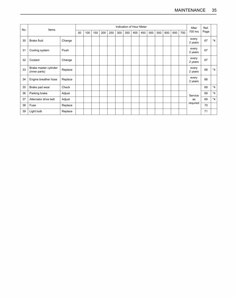
35MAINTENANCE
30 Brake fluid Change every2 years 67 *4
31 Cooling system Flush every2 years 67
32 Coolant Change every2 years 67
33 Brake master cylinder (inner parts) Replace every
2 years 68 *4
34 Engine breather hose Replace every2 years 68
35 Brake pad wear Check
Service as
required
69 *4
36 Parking brake Adjust 69 *4
37 Alternator drive belt Adjust 69 *4
38 Fuse Replace 70
39 Light bulb Replace 71
No. ItemsIndication of Hour Meter After
700 hrsRef.Page50 100 150 200 250 300 350 400 450 500 550 600 650 700
Downloaded from www.Manualslib.com manuals search engine

36 MAINTENANCE
LUBRICANTS, FUEL AND COOLANT
*KUBOTA UDT or SUPER UDT-2 fluid --- KUBOTA original transmission hydraulic fluid**Oil amount when the oil level is at the upper level of the oil level gauge.
No. Locations Capacities Lubricants
1 Fuel 20 L (5.3 U.S.gals.) Automobile unleaded or regular gasolineUnleaded gasoline 87 octane or higher
2 Coolant (with reserve tank) 1.8 L (1.9 U.S.qts.) Fresh clean water with anti-freeze
3 Engine crankcase
[Filter exchanged]1.35 L (1.43 U.S.qts.)**[Filter non-exchanged]1.2 L (1.27 U.S.qts.)**
Engine oil: API Service Classification SG, SH, SJ or higherAbove -18 (0 )...SAE10W-30Below 0 (32 )......SAE5W-20 or 5W-30
4 Transmission case 8.5 L (2.2 U.S.gals.) KUBOTA UDT or SUPER UDT-2 fluid*5 Front axle case 0.21 L (0.22 U.S.qts.) KUBOTA UDT or SUPER UDT-2 fluid*
6 Brake fluid(reservoir and lines)
0.2 L (0.21 U.S.qts.) KUBOTA DOT3 GENUINE BRAKE FLUID
Greasing No. of greasing points Capacity Type of grease
VHT link 1 Until grease overflows Multipurpose GreaseNLGI-2 OR NLGI-1(GC-LB)
Battery terminal 2
Moderate amount Spray Type Grease
Cargo bed pivot 2Parking brake pivot 2
Range gear shift lever pivot 14WD lever pivot 1
Differential lock lever 1Bypass link 1
Downloaded from www.Manualslib.com manuals search engine
37MAINTENANCE
C Engine Oil:Oil used in the engine should have an American Petroleum Institute (API) service classification and Proper SAE EngineOil according to the ambient temperatures as shown above:
C Fuel:A Gasohol (up to 10% ethyl alcohol, 90% unleaded gasoline by volume) is approved for the engine. Other gasoline/
alcohol blends are not approved.
C Transmission oil:To complete lubrication of the transmission, it is important that a multi-grade transmission fluid be used in this system.We recommend the use of KUBOTA UDT or SUPER UDT-2 fluid for optimum protection and performance. (Consultyour local KUBOTA Dealer for further detail.)Do not mix different brands or grades.
C Brake fluid:Always use KUBOTA DOT3 GENUINE BRAKE FLUID from a sealed container. If it is not available, you should use onlyDOT3 fluid as a temporary replacement from a sealed container.However, the use of any non-KUBOTA brake fluid can cause corrosion and decrease the life of the system.Have the brake system flushed and refilled with KUBOTA DOT3 GENUINE BRAKE FLUID as soon as possible.
A Indicated capacity of water and oil are manufacturer's estimate.
Downloaded from www.Manualslib.com manuals search engine

38 PERIODIC SERVICE
PERIODIC SERVICE
To avoid personal injury:A Do not work under any hydraulically supported
devices. They can settle, suddenly leak down,or be accidentally lowered. If necessary to workunder vehicle or any vehicle elements forservicing or adjustment, securely support themwith stands or suitable blocking beforehand.
HOW TO OPEN THE HOOD AND TILT THE SEAT
To avoid personal injury from contact with movingparts;A Never open the operator's seat while the engine
is running.
BHood1. To open the hood, pull up the latch lever to release the
latch and open the hood.2. Push the support link into the hole to lock when the
hood is fully raised.
3. To close the hood, hold the hood and lift up it slightlyand pull the support link to unlock.
4. Put the support link into the support holder.
5. Press-fit the hood into position with both hands.
(1) Latch lever(2) Hood
(A) "RELEASE"
(1) Support link(2) Hole
(A) "HOLD"(B) "PUSH" (Lock)(C) "PULL" (Unlock)
(1) Support holder
Downloaded from www.Manualslib.com manuals search engine

39PERIODIC SERVICE
BOperator's SeatTo open the seat, raise the seat to the forward position.
A For the component below the seat, turn over therubber sheet to work on it as shown in the figure below.
HOW TO RAISE THE CARGO BED
To avoid personal injury:A When servicing under raised bed, make sure
safety support is properly mounted.A Do not touch muffler or exhaust pipes while
they are hot; Severe burns could result.
BRaising and Lowering the Cargo Bed
To avoid personal injury;A Make sure the vehicle is on a firm, level surface
and the parking brake is applied before raisingthe cargo bed and securing the cargo bed in theraised position.
A A loaded cargo bed can be very heavy. Neverraise the cargo bed when it is loaded. Unloadthe cargo bed before raising it by hand.
1. Park the vehicle on a flat surface.2. Empty the cargo bed by hand.3. Release the latches on both sides and then raise the
cargo bed with the hand grip.
4. Push the safety support into the latch slot to lock whenthe cargo is fully raised.
(1) Operator's seat
(1) Rubber sheet (A) Seat
(1) Latch(2) Hand grip
(A) "LOCK"(B) "RELEASE"(C) "RAISE"
Downloaded from www.Manualslib.com manuals search engine

PERIODIC SERVICE40
5. To lower the cargo bed, raise the cargo bed slightlyusing the handgrip.
6. Release the safety support from the latch slot bypulling up on the middle of the support.
7. Put the safety support into the support holder.
8. Slowly lower the cargo bed onto the frame and set thelatches on both sides.
JACK-UP POINT
To avoid personal injury, death or vehicle damage:A Do not work under the vehicle unless it is
secured by safe stands or suitable blocking.
BFront EndJack up at the front bumper only.
BRear EndJack up the rear side after placing a wooden block underthe transmission bottom cover for securing the engine andthen supporting it.Do not jack it up supporting the steel plate portion underthe transmission bottom cover directly.
(1) Safety support(2) Latch slot
(1) Support holder
(1) Front bumper(2) Jack(3) Wooden block
(1) Transmission bottom cover(2) Jack(3) Wooden block
Downloaded from www.Manualslib.com manuals search engine
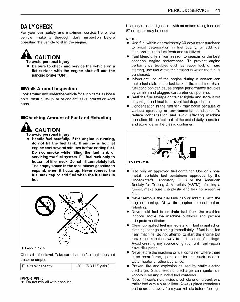
41PERIODIC SERVICE
DAILY CHECKFor your own safety and maximum service life of thevehicle, make a thorough daily inspection beforeoperating the vehicle to start the engine.
To avoid personal injury:A Be sure to check and service the vehicle on a
flat surface with the engine shut off and theparking brake "ON".
BWalk Around InspectionLook around and under the vehicle for such items as loosebolts, trash build-up, oil or coolant leaks, broken or wornparts.
BChecking Amount of Fuel and Refueling
To avoid personal injury:A Handle fuel carefully. If the engine is running,
do not fill the fuel tank. If engine is hot, letengine cool several minutes before adding fuel.Do not smoke while filling the fuel tank orservicing the fuel system. Fill fuel tank only tobottom of filler neck. Do not fill completely full.The empty space in the tank allows gasoline toexpand, when it heats up. Never remove thefuel tank cap or add fuel when the fuel tank ishot.
Check the fuel level. Take care that the fuel tank does notbecome empty.
A Do not mix oil with gasoline.
Use only unleaded gasoline with an octane rating index of87 or higher may be used.
A Use fuel within approximately 30 days after purchaseto avoid deterioration in fuel quality, or add fuelstabilizer to keep fuel fresh and stabilized.
A Fuel blend differs from season to season for the bestseasonal engine performance. To prevent engineperformance troubles such as vapor lock or hardstarting, use fuel within the season in which the fuel ispurchased.
A Infrequent use of the engine during a season canmake fuel stale in the fuel tank of the machine. Stalefuel condition can cause engine performance troublesby varnish and plugged carburetor components.
A Seal the fuel storage container tightly and store it outof sunlight and heat to prevent fuel degradation.
A Condensation in the fuel tank may occur because ofvarious operating or environmental conditions. Toreduce condensation and avoid affecting machineoperation, fill the fuel tank at the end of daily operationand store fuel in the plastic container.
A Use only an approved fuel container. Use only non-metal, portable fuel containers approved by theUnderwriter's Laboratory (U.L.) or the AmericanSociety for Testing & Materials (ASTM). If using afunnel, make sure it is plastic and has no screen orfilter.
A Never remove the fuel tank cap or add fuel with theengine running. Allow the engine to cool beforerefueling.
A Never add fuel to or drain fuel from the machineindoors. Move the machine outdoors and provideadequate ventilation.
A Clean up spilled fuel immediately. If fuel is spilled onclothing, change clothing immediately. If fuel is spillednear machine, do not attempt to start the engine butmove the machine away from the area of spillage.Avoid creating any source of ignition until fuel vaporshave dissipated.
A Never store the machine or fuel container where thereis an open flame, spark, or pilot light such as on awater heater or other appliance.
A Prevent fire and explosion caused by static electricdischarge. Static electric discharge can ignite fuelvapors in an ungrounded fuel container.
A Never fill containers inside a vehicle or on a truck or atrailer bed with a plastic liner. Always place containerson the ground away from your vehicle before fueling.
Fuel tank capacity 20 L (5.3 U.S.gals.)
Downloaded from www.Manualslib.com manuals search engine
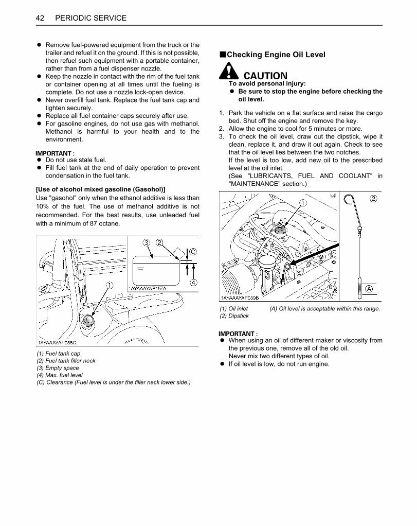
PERIODIC SERVICE42
A Remove fuel-powered equipment from the truck or thetrailer and refuel it on the ground. If this is not possible,then refuel such equipment with a portable container,rather than from a fuel dispenser nozzle.
A Keep the nozzle in contact with the rim of the fuel tankor container opening at all times until the fueling iscomplete. Do not use a nozzle lock-open device.
A Never overfill fuel tank. Replace the fuel tank cap andtighten securely.
A Replace all fuel container caps securely after use.A For gasoline engines, do not use gas with methanol.
Methanol is harmful to your health and to theenvironment.
A Do not use stale fuel.A Fill fuel tank at the end of daily operation to prevent
condensation in the fuel tank.
[Use of alcohol mixed gasoline (Gasohol)]Use "gasohol" only when the ethanol additive is less than10% of the fuel. The use of methanol additive is notrecommended. For the best results, use unleaded fuelwith a minimum of 87 octane.
BChecking Engine Oil Level
To avoid personal injury:A Be sure to stop the engine before checking the
oil level.
1. Park the vehicle on a flat surface and raise the cargobed. Shut off the engine and remove the key.
2. Allow the engine to cool for 5 minutes or more.3. To check the oil level, draw out the dipstick, wipe it
clean, replace it, and draw it out again. Check to seethat the oil level lies between the two notches.If the level is too low, add new oil to the prescribedlevel at the oil inlet.(See "LUBRICANTS, FUEL AND COOLANT" in"MAINTENANCE" section.)
A When using an oil of different maker or viscosity fromthe previous one, remove all of the old oil.Never mix two different types of oil.
A If oil level is low, do not run engine.(1) Fuel tank cap(2) Fuel tank filler neck(3) Empty space(4) Max. fuel level(C) Clearance (Fuel level is under the filler neck lower side.)
(1) Oil inlet(2) Dipstick
(A) Oil level is acceptable within this range.
Downloaded from www.Manualslib.com manuals search engine
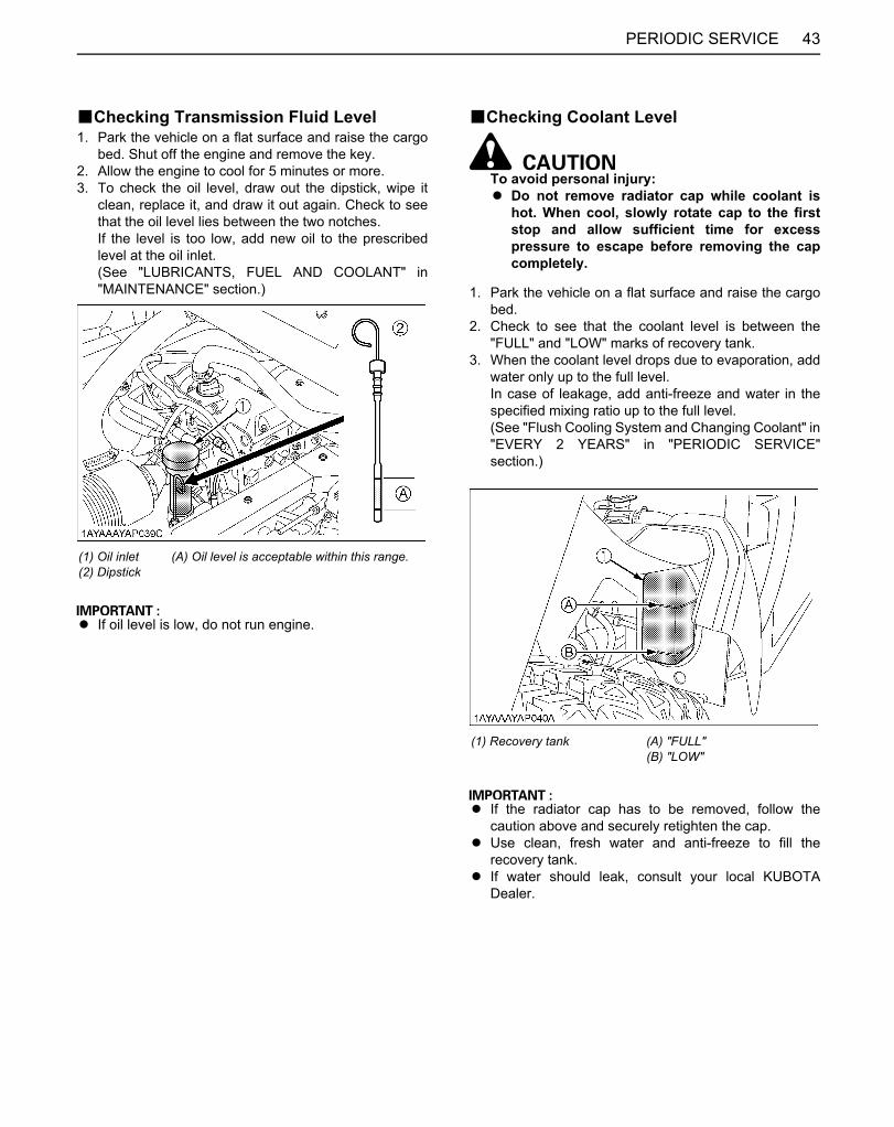
43PERIODIC SERVICE
BChecking Transmission Fluid Level1. Park the vehicle on a flat surface and raise the cargo
bed. Shut off the engine and remove the key.2. Allow the engine to cool for 5 minutes or more.3. To check the oil level, draw out the dipstick, wipe it
clean, replace it, and draw it out again. Check to seethat the oil level lies between the two notches.If the level is too low, add new oil to the prescribedlevel at the oil inlet.(See "LUBRICANTS, FUEL AND COOLANT" in"MAINTENANCE" section.)
A If oil level is low, do not run engine.
BChecking Coolant Level
To avoid personal injury:A Do not remove radiator cap while coolant is
hot. When cool, slowly rotate cap to the firststop and allow sufficient time for excesspressure to escape before removing the capcompletely.
1. Park the vehicle on a flat surface and raise the cargobed.
2. Check to see that the coolant level is between the"FULL" and "LOW" marks of recovery tank.
3. When the coolant level drops due to evaporation, addwater only up to the full level.In case of leakage, add anti-freeze and water in thespecified mixing ratio up to the full level.(See "Flush Cooling System and Changing Coolant" in"EVERY 2 YEARS" in "PERIODIC SERVICE"section.)
A If the radiator cap has to be removed, follow thecaution above and securely retighten the cap.
A Use clean, fresh water and anti-freeze to fill therecovery tank.
A If water should leak, consult your local KUBOTADealer.
(1) Oil inlet (2) Dipstick
(A) Oil level is acceptable within this range.
(1) Recovery tank (A) "FULL"(B) "LOW"
Downloaded from www.Manualslib.com manuals search engine
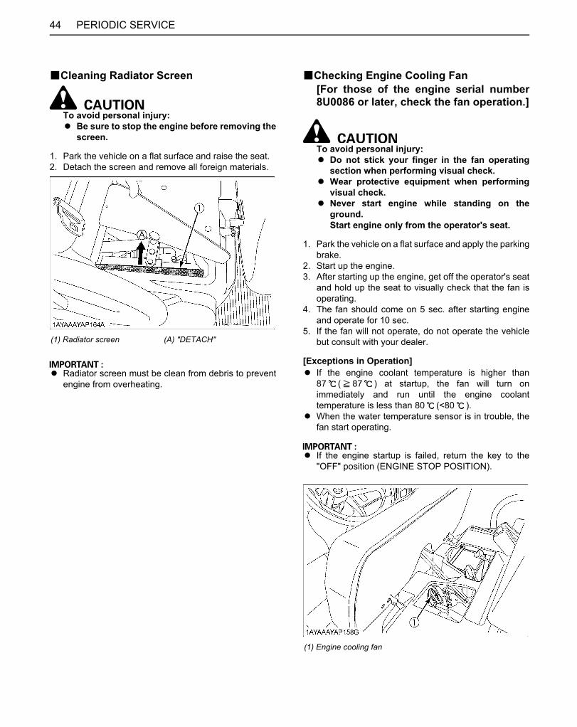
PERIODIC SERVICE44
BCleaning Radiator Screen
To avoid personal injury:A Be sure to stop the engine before removing the
screen.
1. Park the vehicle on a flat surface and raise the seat.2. Detach the screen and remove all foreign materials.
A Radiator screen must be clean from debris to preventengine from overheating.
BChecking Engine Cooling Fan[For those of the engine serial number8U0086 or later, check the fan operation.]
To avoid personal injury:A Do not stick your finger in the fan operating
section when performing visual check.A Wear protective equipment when performing
visual check.A Never start engine while standing on the
ground.Start engine only from the operator's seat.
1. Park the vehicle on a flat surface and apply the parkingbrake.
2. Start up the engine.3. After starting up the engine, get off the operator's seat
and hold up the seat to visually check that the fan isoperating.
4. The fan should come on 5 sec. after starting engineand operate for 10 sec.
5. If the fan will not operate, do not operate the vehiclebut consult with your dealer.
[Exceptions in Operation]A If the engine coolant temperature is higher than
87 ( 87 ) at startup, the fan will turn onimmediately and run until the engine coolanttemperature is less than 80 (<80 ).
A When the water temperature sensor is in trouble, thefan start operating.
A If the engine startup is failed, return the key to the"OFF" position (ENGINE STOP POSITION).
(1) Radiator screen (A) "DETACH"
(1) Engine cooling fan
Downloaded from www.Manualslib.com manuals search engine

45PERIODIC SERVICE
BChecking Brake Fluid Level
To avoid personal injury:A Never operate the vehicle, if the brake fluid is
below the "MIN" mark.A Use only KUBOTA DOT3 GENUINE BRAKE
FLUID from a sealed container. Using othertype of oil ruins synthetic resin or rubberinstalled in brake system components, andmay cause brake failure.
A Avoid contamination of the brake fluid.Thoroughly clean area around the filler capbefore removing. Do not open the brake fluidreservoir cap unless absolutely necessary.
A Use extreme care when filling the reservoir. Ifbrake fluid is spilled on power steering hose,wash off with water immediately. Brake fluidquickly ruins synthetic resin or rubber hoses.
1. Park the vehicle on a level ground and open the hood.2. Check to see that the brake fluid level is between the
"MAX" and "MIN" marks.3. If it is below the "MIN" mark, add brake fluid to the
"MAX" mark.
BChecking Brake Pedal
To avoid personal injury:A Stop the engine and chock the wheels before
checking brake pedal.
1. Inspect the brake pedals for free travel, and smoothoperation.
2. Adjust if incorrect measurement is found: (See"Checking Brake Pedal" in "EVERY 200 HOURS" in"PERIODIC SERVICE" section.)
(1) Oil tank cap (A) "MAX"(B) "MIN"
(1) Brake pedal (A) "FREE TRAVEL"(B) "PEDAL STROKE"
Downloaded from www.Manualslib.com manuals search engine
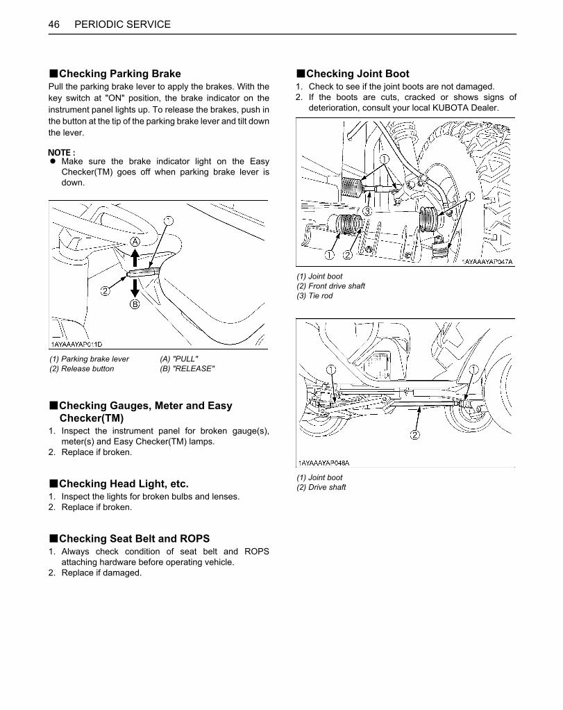
PERIODIC SERVICE46
BChecking Parking BrakePull the parking brake lever to apply the brakes. With thekey switch at "ON" position, the brake indicator on theinstrument panel lights up. To release the brakes, push inthe button at the tip of the parking brake lever and tilt downthe lever.
A Make sure the brake indicator light on the EasyChecker(TM) goes off when parking brake lever isdown.
BChecking Gauges, Meter and Easy Checker(TM)
1. Inspect the instrument panel for broken gauge(s),meter(s) and Easy Checker(TM) lamps.
2. Replace if broken.
BChecking Head Light, etc.1. Inspect the lights for broken bulbs and lenses.2. Replace if broken.
BChecking Seat Belt and ROPS1. Always check condition of seat belt and ROPS
attaching hardware before operating vehicle.2. Replace if damaged.
BChecking Joint Boot1. Check to see if the joint boots are not damaged.2. If the boots are cuts, cracked or shows signs of
deterioration, consult your local KUBOTA Dealer.
(1) Parking brake lever(2) Release button
(A) "PULL"(B) "RELEASE"
(1) Joint boot(2) Front drive shaft(3) Tie rod
(1) Joint boot(2) Drive shaft
Downloaded from www.Manualslib.com manuals search engine
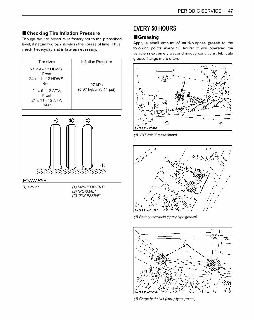
47PERIODIC SERVICE
BChecking Tire Inflation PressureThough the tire pressure is factory-set to the prescribedlevel, it naturally drops slowly in the course of time. Thus,check it everyday and inflate as necessary.
EVERY 50 HOURSBGreasingApply a small amount of multi-purpose grease to thefollowing points every 50 hours: If you operated thevehicle in extremely wet and muddy conditions, lubricategrease fittings more often.
Tire sizes Inflation Pressure
24 x 9 - 12 HDWS,Front
24 x 11 - 12 HDWS,Rear 97 kPa
(0.97 kgf/cm , 14 psi)24 x 9 - 12 ATV,Front
24 x 11 - 12 ATV,Rear
(1) Ground (A) "INSUFFICIENT"(B) "NORMAL"(C) "EXCESSIVE"
(1) VHT link (Grease fitting)
(1) Battery terminals (spray type grease)
(1) Cargo bed pivot (spray type grease)
Downloaded from www.Manualslib.com manuals search engine

PERIODIC SERVICE48
(1) Parking brake pivot (spray type grease) (1) Range gear shift lever pivot (spray type grease)(2) 4WD lever pivot (spray type grease)(3) Differential lock lever (spray type grease)
(1) Bypass link (spray type grease)
Downloaded from www.Manualslib.com manuals search engine

49PERIODIC SERVICE
BChecking Engine Start System
To avoid personal injury:A Do not allow anyone near the vehicle while
testing.A If the vehicle does not pass the test do not
operate the vehicle.
C Preparation before testing.1. Place all control levers in the "NEUTRAL" position.2. Set the parking brake and stop the engine.
C Test: Range gear shift lever safety switch1. Sit on the operator's seat.2. Shift the range gear shift lever to "H" position.3. Return the Speed control pedal to the "N" position.4. Turn the key to "START" position.5. The engine must not crank.6. Repeat the step 2 to 5 with the range gear shift lever
at "L" and "R" each position.
EVERY 100 HOURSBChecking VHT Neutral Spring1. Park the vehicle on a flat place.2. Apply the parking brake.3. Shift the range gear shift lever to the neutral position.4. Start the engine.5. Make sure that the rotation speed of the engine
returns to the idling rotation immediately when takingthe foot off the pedal, after depressing the speedcontrol pedal several times. If the above does notoccur immediately, consult your local KUBOTA dealerfor this service.
BChecking Wheel Bolt Torque
To avoid personal injury:A Never operate vehicle with a loose wheel bolts.A Any time bolts are loosened, retighten to the
specified torque.A Check all bolts frequently and keep them tight.
Check wheel bolts regularly especially when new. If theyare loose, tighten them as follows.
(1) Torque wheel bolts to 108.4 to 121.9 N-m (11 to 12.4 kgf-m) (80 to 90 ft-lbs.)
Downloaded from www.Manualslib.com manuals search engine

PERIODIC SERVICE50
BCleaning Air Cleaner Primary Element1. Remove the air cleaner cover and primary element.2. Clean the primary element:
(1) When dry dust adheres to the element, blowcompressed air from the inside, turning theelement. Pressure of compressed air must beunder 205 kPa (2.1 kgf/cm , 30 psi).
(2) When carbon or oil adheres to the element,replace the element with new one even if it hasnot been used for 1 year.
3. Replace the primary element:Once yearly or after every sixth cleaning, whichevercomes first.
A Check to see if the evacuator valve is blocked withdust.
A Check the rubber seal. Replace if damaged.
A The air cleaner uses a dry element, never apply oil.A Do not run the engine with filter element removed.A Be sure to refit the cover with the arrow (on the rear of
cover) upright. If the cover is improperly fitted,evacuator valve will not function and dust will adhereto the element.
A Do not touch the secondary element except in caseswhere replacing is required.(See "Replacing Air Cleaner Secondary Element" in"EVERY 1 YEAR" in "PERIODIC SERVICE" section.)
C Evacuator ValveOpen the evacuator valve once a week under ordinaryconditions - or daily when used in a dusty place - to get ridof large particles of dust and dirt.
BCleaning Pre Cleaner Element1. Remove the Pre cleaner element.
2. Wash the pre cleaner in warm water with detergent.Rinse the pre cleaner thoroughly until all traces ofdetergent are eliminated.Squeeze out excess water. Allow the pre cleaner to airdry.
3. Reinstall the pre cleaner.
(1) Secondary (safety) element(2) Primary element(3) Rubber seal(4) Evacuator valve(5) Cover
(1) Pre cleaner element(2) Intake air line
Downloaded from www.Manualslib.com manuals search engine
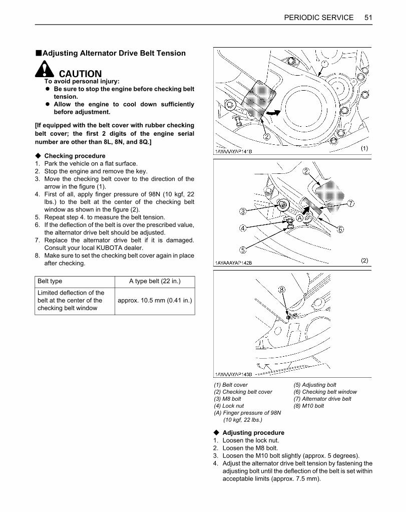
51PERIODIC SERVICE
BAdjusting Alternator Drive Belt Tension
To avoid personal injury:A Be sure to stop the engine before checking belt
tension.A Allow the engine to cool down sufficiently
before adjustment.
[If equipped with the belt cover with rubber checkingbelt cover; the first 2 digits of the engine serialnumber are other than 8L, 8N, and 8Q.]
C Checking procedure1. Park the vehicle on a flat surface.2. Stop the engine and remove the key.3. Move the checking belt cover to the direction of the
arrow in the figure (1).4. First of all, apply finger pressure of 98N (10 kgf, 22
lbs.) to the belt at the center of the checking beltwindow as shown in the figure (2).
5. Repeat step 4. to measure the belt tension.6. If the deflection of the belt is over the prescribed value,
the alternator drive belt should be adjusted.7. Replace the alternator drive belt if it is damaged.
Consult your local KUBOTA dealer.8. Make sure to set the checking belt cover again in place
after checking.
C Adjusting procedure1. Loosen the lock nut.2. Loosen the M8 bolt.3. Loosen the M10 bolt slightly (approx. 5 degrees).4. Adjust the alternator drive belt tension by fastening the
adjusting bolt until the deflection of the belt is set withinacceptable limits (approx. 7.5 mm).
Belt type A type belt (22 in.)
Limited deflection of the belt at the center of the checking belt window
approx. 10.5 mm (0.41 in.)
(1) Belt cover(2) Checking belt cover(3) M8 bolt(4) Lock nut(A) Finger pressure of 98N (10 kgf, 22 lbs.)
(5) Adjusting bolt(6) Checking belt window(7) Alternator drive belt(8) M10 bolt
Downloaded from www.Manualslib.com manuals search engine
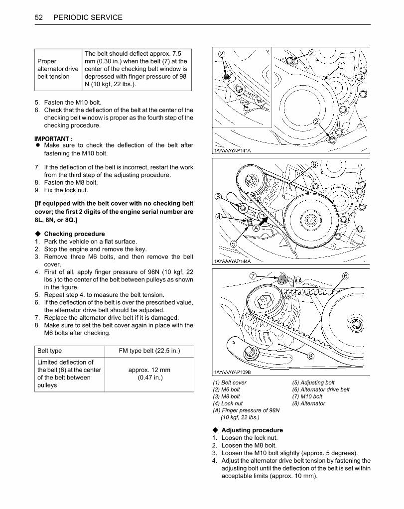
PERIODIC SERVICE52
5. Fasten the M10 bolt.6. Check that the deflection of the belt at the center of the
checking belt window is proper as the fourth step of thechecking procedure.
A Make sure to check the deflection of the belt afterfastening the M10 bolt.
7. If the deflection of the belt is incorrect, restart the workfrom the third step of the adjusting procedure.
8. Fasten the M8 bolt.9. Fix the lock nut.
[If equipped with the belt cover with no checking beltcover; the first 2 digits of the engine serial number are8L, 8N, or 8Q.]
C Checking procedure1. Park the vehicle on a flat surface.2. Stop the engine and remove the key.3. Remove three M6 bolts, and then remove the belt
cover.4. First of all, apply finger pressure of 98N (10 kgf, 22
lbs.) to the center of the belt between pulleys as shownin the figure.
5. Repeat step 4. to measure the belt tension.6. If the deflection of the belt is over the prescribed value,
the alternator drive belt should be adjusted.7. Replace the alternator drive belt if it is damaged.8. Make sure to set the belt cover again in place with the
M6 bolts after checking.
C Adjusting procedure1. Loosen the lock nut.2. Loosen the M8 bolt.3. Loosen the M10 bolt slightly (approx. 5 degrees).4. Adjust the alternator drive belt tension by fastening the
adjusting bolt until the deflection of the belt is set withinacceptable limits (approx. 10 mm).
Proper alternator drive belt tension
The belt should deflect approx. 7.5 mm (0.30 in.) when the belt (7) at the center of the checking belt window is depressed with finger pressure of 98 N (10 kgf, 22 lbs.).
Belt type FM type belt (22.5 in.)
Limited deflection of the belt (6) at the center of the belt between pulleys
approx. 12 mm (0.47 in.)
(1) Belt cover(2) M6 bolt(3) M8 bolt(4) Lock nut(A) Finger pressure of 98N (10 kgf, 22 lbs.)
(5) Adjusting bolt(6) Alternator drive belt(7) M10 bolt(8) Alternator
Downloaded from www.Manualslib.com manuals search engine

53PERIODIC SERVICE
5. Fasten the M10 bolt.6. Check that the deflection of the center of the belt
between pulleys is proper as the fourth step of thechecking procedure.
A Make sure to check the deflection of the belt afterfastening the M10 bolt.
7. If the deflection of the belt is incorrect, restart the workfrom the third step of the adjusting procedure.
8. Fasten the M8 bolt.9. Fix the lock nut.
BChecking Fuel Line
To avoid personal injury:A Be sure to stop the engine and remove the key
when attempting to make the following checksand changes.
A Never fail to check the fuel lines periodically.The fuel lines are subject to wear and aging.Fuel may leak out onto the running engine,causing a fire.
The fuel line connections should be checked annually orevery 100 service hours, whichever comes first.1. Park the vehicle on a flat surface and raise the cargo
bed.2. The fuel line is made of rubber and ages regardless of
service period.3. If the fuel line and clamps are found to be damaged or
deteriorated, replace them.
A When the fuel line is disconnected for maintenance orrepair, close both ends of the fuel line with a piece ofclean cloth or paper to prevent dust and dirt fromentering. In addition, particular care must be taken notto admit dust and dirt into the fuel pump. Entrance ofeven a small amount of dust or dirt cause prematurewear and malfunction of the fuel pump and injectorcomponents.
Proper alternator drive belt tension
The belt should deflect approx. 10 mm (0.39 in.) when the center of the belt between pulleys is depressed with finger pressure of 98 N (10 kgf, 22 lbs.).
(1) Hose clamp(2) Fuel line
(1) Hose clamp(2) Fuel line(3) Fuel pump with filter
Downloaded from www.Manualslib.com manuals search engine
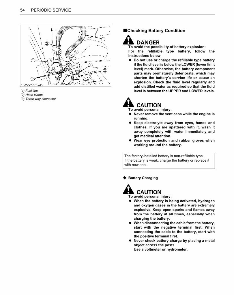
PERIODIC SERVICE54
BChecking Battery Condition
To avoid the possibility of battery explosion:For the refillable type battery, follow theinstructions below.A Do not use or charge the refillable type battery
if the fluid level is below the LOWER (lower limitlevel) mark. Otherwise, the battery componentparts may prematurely deteriorate, which mayshorten the battery's service life or cause anexplosion. Check the fluid level regularly andadd distilled water as required so that the fluidlevel is between the UPPER and LOWER levels.
To avoid personal injury:A Never remove the vent caps while the engine is
running.A Keep electrolyte away from eyes, hands and
clothes. If you are spattered with it, wash itaway completely with water immediately andget medical attention.
A Wear eye protection and rubber gloves whenworking around the battery.
C Battery Charging
To avoid personal injury:A When the battery is being activated, hydrogen
and oxygen gases in the battery are extremelyexplosive. Keep open sparks and flames awayfrom the battery at all times, especially whencharging the battery.
A When disconnecting the cable from the battery,start with the negative terminal first. Whenconnecting the cable to the battery, start withthe positive terminal first.
A Never check battery charge by placing a metalobject across the posts.Use a voltmeter or hydrometer.
(1) Fuel line(2) Hose clamp(3) Three way connector
The factory-installed battery is non-refillable type.If the battery is weak, charge the battery or replace it with new one.
Downloaded from www.Manualslib.com manuals search engine
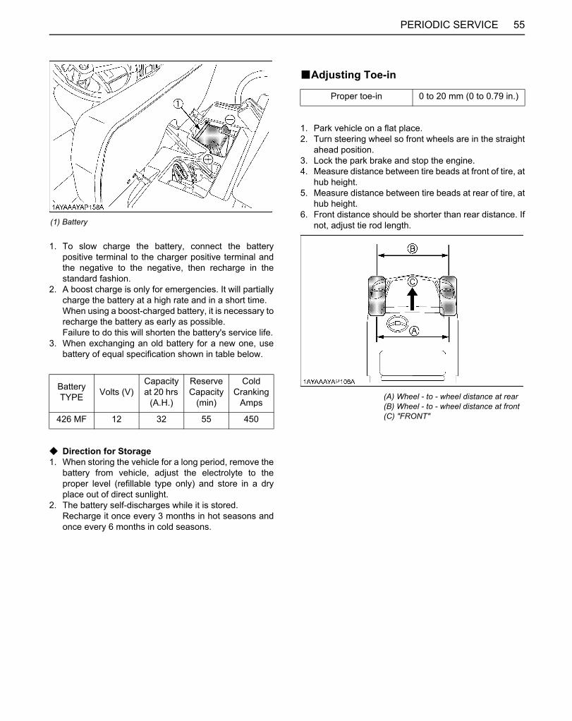
55PERIODIC SERVICE
1. To slow charge the battery, connect the batterypositive terminal to the charger positive terminal andthe negative to the negative, then recharge in thestandard fashion.
2. A boost charge is only for emergencies. It will partiallycharge the battery at a high rate and in a short time.When using a boost-charged battery, it is necessary torecharge the battery as early as possible.Failure to do this will shorten the battery's service life.
3. When exchanging an old battery for a new one, usebattery of equal specification shown in table below.
C Direction for Storage1. When storing the vehicle for a long period, remove the
battery from vehicle, adjust the electrolyte to theproper level (refillable type only) and store in a dryplace out of direct sunlight.
2. The battery self-discharges while it is stored.Recharge it once every 3 months in hot seasons andonce every 6 months in cold seasons.
BAdjusting Toe-in
1. Park vehicle on a flat place.2. Turn steering wheel so front wheels are in the straight
ahead position.3. Lock the park brake and stop the engine.4. Measure distance between tire beads at front of tire, at
hub height.5. Measure distance between tire beads at rear of tire, at
hub height.6. Front distance should be shorter than rear distance. If
not, adjust tie rod length.(1) Battery
Battery TYPE Volts (V)
Capacityat 20 hrs
(A.H.)
Reserve Capacity
(min)
ColdCranking
Amps
426 MF 12 32 55 450
Proper toe-in 0 to 20 mm (0 to 0.79 in.)
(A) Wheel - to - wheel distance at rear(B) Wheel - to - wheel distance at front(C) "FRONT"
Downloaded from www.Manualslib.com manuals search engine
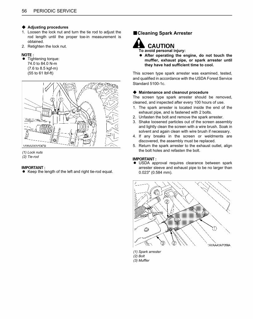
PERIODIC SERVICE56
C Adjusting procedures1. Loosen the lock nut and turn the tie rod to adjust the
rod length until the proper toe-in measurement isobtained.
2. Retighten the lock nut.
A Tightening torque:74.0 to 84.0 N-m(7.6 to 8.5 kgf-m)(55 to 61 lbf-ft)
A Keep the length of the left and right tie-rod equal.
BCleaning Spark Arrester
To avoid personal injury:A After operating the engine, do not touch the
muffler, exhaust pipe, or spark arrester untilthey have had sufficient time to cool.
This screen type spark arrester was examined, tested,and qualified in accordance with the USDA Forest ServiceStandard 5100-1c.
C Maintenance and cleanout procedureThe screen type spark arrester should be removed,cleaned, and inspected after every 100 hours of use.1. The spark arrester is located inside the end of the
exhaust pipe, and is fastened with 2 bolts.2. Unfasten the bolt and remove the spark arrester.3. Shake loosened particles out of the screen assembly
and lightly clean the screen with a wire brush. Soak insolvent and again clean with wire brush if necessary.
4. If any breaks in the screen or weldments arediscovered, the assembly must be replaced.
5. Return the spark arrester to the exhaust outlet, alignthe bolt holes and refasten the bolt.
A USDA approval requires clearance between sparkarrester sleeve and exhaust pipe to be no larger than0.023" (0.584 mm).
(1) Lock nuts(2) Tie-rod
(1) Spark arrester(2) Bolt(3) Muffler
Downloaded from www.Manualslib.com manuals search engine
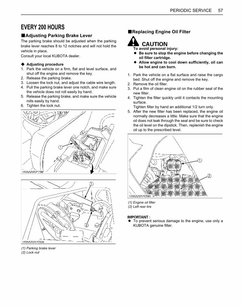
57PERIODIC SERVICE
EVERY 200 HOURSBAdjusting Parking Brake LeverThe parking brake should be adjusted when the parkingbrake lever reaches 8 to 12 notches and will not hold thevehicle in place.Consult your local KUBOTA dealer.
C Adjusting procedure1. Park the vehicle on a firm, flat and level surface, and
shut off the engine and remove the key.2. Release the parking brake.3. Loosen the lock nut, and adjust the cable wire length.4. Pull the parking brake lever one notch, and make sure
the vehicle does not roll easily by hand.5. Release the parking brake, and make sure the vehicle
rolls easily by hand.6. Tighten the lock nut.
BReplacing Engine Oil Filter
To avoid personal injury:A Be sure to stop the engine before changing the
oil filter cartridge.A Allow engine to cool down sufficiently, oil can
be hot and can burn.
1. Park the vehicle on a flat surface and raise the cargobed. Shut off the engine and remove the key.
2. Remove the oil filter.3. Put a film of clean engine oil on the rubber seal of the
new filter.4. Tighten the filter quickly until it contacts the mounting
surface.Tighten filter by hand an additional 1/2 turn only.
5. After the new filter has been replaced, the engine oilnormally decreases a little. Make sure that the engineoil does not leak through the seal and be sure to checkthe oil level on the dipstick. Then, replenish the engineoil up to the prescribed level.
A To prevent serious damage to the engine, use only aKUBOTA genuine filter.
(1) Parking brake lever(2) Lock nut
(1) Engine oil filter(2) Left rear tire
Downloaded from www.Manualslib.com manuals search engine

PERIODIC SERVICE58
BChanging Engine Oil
To avoid personal injury:A Be sure to stop the engine before changing the
oil.A Allow engine to cool down sufficiently, oil can
be hot and can burn.
1. Park the vehicle on a flat surface and raise the cargobed. Shut off the engine and remove the key.
2. To drain the used oil, remove the drain plug at thebottom of the engine and completely drain the oil intoan oil pan.All the used oil can be drained out easily when theengine is still warm.
3. After draining, reinstall the drain plug.4. Fill with the new oil up to the upper notch on the
dipstick.(See "LUBRICANTS, FUEL AND COOLANT" in"MAINTENANCE" section.)
Oil capacity
[Filter exchanged]1.35 L (1.43 U.S.qts.)[Filter non-exchanged]1.2 L (1.27 U.S.qts.)
(1) Oil inlet(2) Dipstick
(A) Oil level is acceptable within this range
(1) Drain plug
Downloaded from www.Manualslib.com manuals search engine

59PERIODIC SERVICE
BCleaning Radiator Cooling Fins
To avoid personal injury:A Compressed air can cause debris to fly a long
distance.A Clear work area of bystanders.A Wear eye protection when using compressed
air for cleaning purposes.A Reduce compressed air pressure to 210 kPa
(2.1 kgf/cm , 30psi)
1. Park the vehicle on a flat surface and raise the seat.2. Remove the radiator maintenance cover.
3. Detach the radiator screen.
4. Remove all dirt and debris from radiator fins and fanshroud using compressed air or water.Flow of compressed air or water should be from theback to the front as shown in the figures.
5. Reinstall the radiator screen and the maintenancecover.
(1) Radiator maintenance cover(2) Knob bolt
(1) Radiator screen (A) "DETACH"
(1) Air blow(2) Fan
Downloaded from www.Manualslib.com manuals search engine

PERIODIC SERVICE60
BReplacing Transmission Oil Filter
To avoid personal injury:A Be sure to stop the engine before changing the
oil filter cartridge.A Allow engine to cool down sufficiently, oil can
be hot and can burn.
1. Remove the drain plug at the bottom of thetransmission case and drain the oil completely into theoil pan.
2. Check the rubber washer on the drain plug. Replace itif missing or in poor condition.
3. After draining, reinstall the drain plug.4. Remove the oil filters.5. Put a film of clean transmission oil on the rubber seal
of the new filter.6. Quickly tighten the filter until it contacts the mounting
surface, then, with a filter wrench, tighten it anadditional 2/3 turn only.
7. After the new filter has been replaced, fill thetransmission oil up to the upper notch on the dipstick.
8. After running the engine for a few minutes, stop theengine and check the oil level again, add oil to theprescribed level.
9. Make sure that the transmission fluid doesn't leak pastthe seal on the filters.
A To prevent serious damage to the transmission, useonly a KUBOTA genuine filter.
(1) Transmission oil filter (HST) (Yellow color)(2) Transmission oil filter (Suction) (Orange color)
(1) Drain plug
(1) Oil inlet(2) Dipstick
(A) Oil level is acceptable within this range
Downloaded from www.Manualslib.com manuals search engine

61PERIODIC SERVICE
BChecking Spark Plug Condition & GapRemove the spark plugs, check condition, and reset thegap or replace with new plugs as necessary.1. Raise the cargo bed.2. Before removing spark plugs, clean the area around
the base of the plug to keep dirt and debris out of theengine.
3. Remove the spark plug wires from spark plugs.4. Use a spark plug wrench to remove the spark plugs.5. Remove plugs and check its condition.
Replace the plug if worn or reuse is questionable.6. Inspect spark plugs for cracked porcelain, pitted
electrodes, or other wear and damage. Replace thespark plug if necessary.
A Do not clean the spark plug in a machine usingabrasive grit. Some grit could remain in the spark plugand enter the engine causing extensive wear anddamage.
7. Check the gap using a wire feeler gauge. Adjust thegap from 0.6 to 0.7 mm (0.024 to 0.028 in.) by carefullybending the ground electrode.
8. Reinstall the spark plug into the cylinder head.
(1) Spark plug
Recommended spark plug NGK BKR4E
Tightening torque(initial)
12 to 15 N-m(8.9 to 11 lbf-ft)
Retightening torque 23 to 27 N-m(17 to 19 lbf-ft)
Downloaded from www.Manualslib.com manuals search engine

PERIODIC SERVICE62
BChecking Brake Pedal
To avoid personal injury:A Stop the engine and chock the wheels before
checking brake pedal.A If movement is outside of the specifications,
contact your local KUBOTA Dealer foradjusting the brake.
C Checking the brake pedal free travel
1. Release the parking brake.2. Slightly depress the brake pedal and measure free
travel at the top of the pedal stroke.3. If brake pedal free travel is outside of the
specifications, contact your local KUBOTA Dealer foradjusting the brake.
C Checking the brake pedal stroke
1. Release the parking brake.2. Step on the pedal and measure the pedal stroke.3. If brake pedal stroke is outside of the specifications,
contact your local KUBOTA Dealer for adjusting thebrake.
BChecking Brake Hose and Pipe1. Check to see that brake hose and pipe are not swollen,
hardened or cracked.2. Check the brake hose and pipe joints for oil leaks.3. If there is any abnormality, consult your local KUBOTA
Dealer for this service.
Proper brake pedalfree travel
7 to 14 mm (0.3 to 0.6 in.)on the pedal
Pedal stroke Less than 65 mm (2.56 in.)on the pedal
(1) Brake pedal (A) "FREE TRAVEL"(B) "PEDAL STROKE"
(1) Brake pipe
(1) Brake hose (Front)
(1) Brake hose(2) Brake pipe
Downloaded from www.Manualslib.com manuals search engine

63PERIODIC SERVICE
BChecking Brake Light Switch1. Park the vehicle on a flat surface.2. Step on the brake pedal to check if the brake light
comes on.3. If it does not, check the bulb or brake light switch.
BChecking Radiator Hose and ClampPark the vehicle on a flat surface and raise the cargo bed.Check to see if radiator hoses are properly fixed every 200hours of operation or 6 months, whichever comes first.1. If hose clamps are loose or water leaks, tighten bands
securely.2. Replace hoses and tighten hose clamps securely, if
radiator hoses are swollen, hardened or cracked.Replace hoses and hose clamps every 2 years or earlierif checked and found that hoses are swollen, hardened orcracked.
(1) Brake hose (Rear)
(1) Brake light switch (A) "FRONT"
(1) Radiator hoses(2) Clamp bands
(1) Radiator hoses(2) Clamp bands
Downloaded from www.Manualslib.com manuals search engine
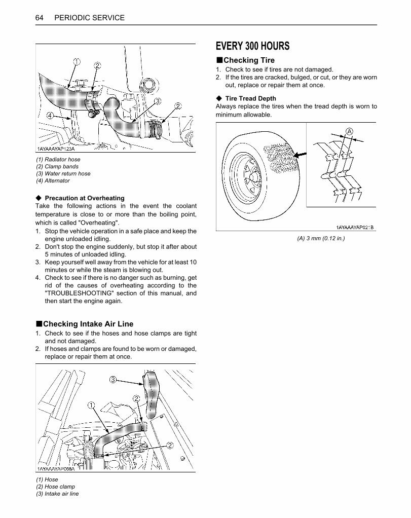
PERIODIC SERVICE64
C Precaution at OverheatingTake the following actions in the event the coolanttemperature is close to or more than the boiling point,which is called "Overheating".1. Stop the vehicle operation in a safe place and keep the
engine unloaded idling.2. Don't stop the engine suddenly, but stop it after about
5 minutes of unloaded idling.3. Keep yourself well away from the vehicle for at least 10
minutes or while the steam is blowing out.4. Check to see if there is no danger such as burning, get
rid of the causes of overheating according to the"TROUBLESHOOTING" section of this manual, andthen start the engine again.
BChecking Intake Air Line1. Check to see if the hoses and hose clamps are tight
and not damaged.2. If hoses and clamps are found to be worn or damaged,
replace or repair them at once.
EVERY 300 HOURSBChecking Tire1. Check to see if tires are not damaged.2. If the tires are cracked, bulged, or cut, or they are worn
out, replace or repair them at once.
C Tire Tread DepthAlways replace the tires when the tread depth is worn tominimum allowable.
(1) Radiator hose(2) Clamp bands(3) Water return hose(4) Alternator
(1) Hose(2) Hose clamp(3) Intake air line
(A) 3 mm (0.12 in.)
Downloaded from www.Manualslib.com manuals search engine
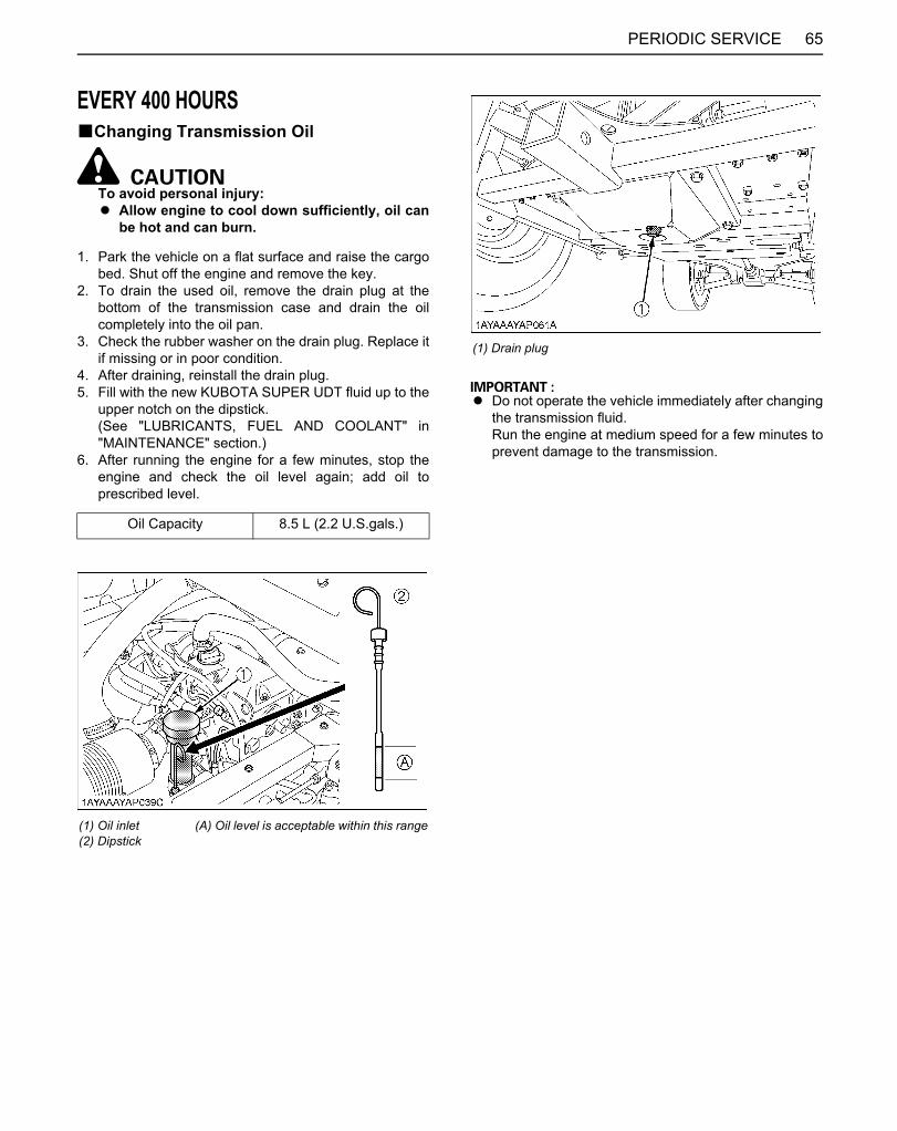
65PERIODIC SERVICE
EVERY 400 HOURSBChanging Transmission Oil
To avoid personal injury:A Allow engine to cool down sufficiently, oil can
be hot and can burn.
1. Park the vehicle on a flat surface and raise the cargobed. Shut off the engine and remove the key.
2. To drain the used oil, remove the drain plug at thebottom of the transmission case and drain the oilcompletely into the oil pan.
3. Check the rubber washer on the drain plug. Replace itif missing or in poor condition.
4. After draining, reinstall the drain plug.5. Fill with the new KUBOTA SUPER UDT fluid up to the
upper notch on the dipstick.(See "LUBRICANTS, FUEL AND COOLANT" in"MAINTENANCE" section.)
6. After running the engine for a few minutes, stop theengine and check the oil level again; add oil toprescribed level.
A Do not operate the vehicle immediately after changingthe transmission fluid.Run the engine at medium speed for a few minutes toprevent damage to the transmission.
Oil Capacity 8.5 L (2.2 U.S.gals.)
(1) Oil inlet(2) Dipstick
(A) Oil level is acceptable within this range
(1) Drain plug
Downloaded from www.Manualslib.com manuals search engine

PERIODIC SERVICE66
BChanging Front Axle Case Oil1. Park the vehicle on a firm, flat and level surface.2. To drain the used oil, remove the drain and filling plugs
at the front axle case and drain the oil completely intothe oil pan.
3. After draining, reinstall the drain plug.4. Fill with the new oil up to the upper notch on the
dipstick.(See "LUBRICANTS, FUEL AND COOLANT" in"MAINTENANCE" section.)
5. After filling, reinstall the filling plug.
EVERY 500 HOURSBAdjusting Engine Valve ClearanceIf you do not have the proper tools and/or are notmechanically proficient, consult your local KUBOTADealer for this service.
BChecking Engine Timing BeltIf you do not have the proper tools and/or are notmechanically proficient, consult your local KUBOTADealer for this service.
EVERY 1000 HOURSBReplacing Engine Timing BeltIf you do not have the proper tools and/or are notmechanically proficient, consult your local KUBOTADealer for this service.
EVERY AFTER 1000 HOURSBCleaning Engine Combustion ChamberIf you do not have the proper tools and/or are notmechanically proficient, consult your local KUBOTADealer for this service.
EVERY 1 YEARBReplacing Air Cleaner Primary Element
and Secondary Element(See "Cleaning Air Cleaner Primary Element" in "EVERY100 HOURS" in "PERIODIC SERVICE" section.)
BReplacing Pre Cleaner Element(See "Cleaning Pre Cleaner Element" in "EVERY 100HOURS" in "PERIODIC SERVICE" section.)
Oil capacity 0.21 L (0.22 U.S.qts.)
(1) Drain plug(2) Filling plug with dipstick
(A) Oil level is acceptable within this range
Downloaded from www.Manualslib.com manuals search engine
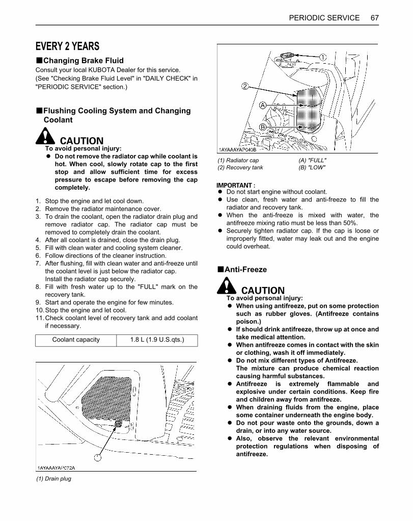
67PERIODIC SERVICE
EVERY 2 YEARSBChanging Brake FluidConsult your local KUBOTA Dealer for this service.(See "Checking Brake Fluid Level" in "DAILY CHECK" in"PERIODIC SERVICE" section.)
BFlushing Cooling System and Changing Coolant
To avoid personal injury:A Do not remove the radiator cap while coolant is
hot. When cool, slowly rotate cap to the firststop and allow sufficient time for excesspressure to escape before removing the capcompletely.
1. Stop the engine and let cool down.2. Remove the radiator maintenance cover.3. To drain the coolant, open the radiator drain plug and
remove radiator cap. The radiator cap must beremoved to completely drain the coolant.
4. After all coolant is drained, close the drain plug.5. Fill with clean water and cooling system cleaner.6. Follow directions of the cleaner instruction.7. After flushing, fill with clean water and anti-freeze until
the coolant level is just below the radiator cap.Install the radiator cap securely.
8. Fill with fresh water up to the "FULL" mark on therecovery tank.
9. Start and operate the engine for few minutes.10.Stop the engine and let cool.11.Check coolant level of recovery tank and add coolant
if necessary.
A Do not start engine without coolant.A Use clean, fresh water and anti-freeze to fill the
radiator and recovery tank.A When the anti-freeze is mixed with water, the
antifreeze mixing ratio must be less than 50%.A Securely tighten radiator cap. If the cap is loose or
improperly fitted, water may leak out and the enginecould overheat.
BAnti-Freeze
To avoid personal injury:A When using antifreeze, put on some protection
such as rubber gloves. (Antifreeze containspoison.)
A If should drink antifreeze, throw up at once andtake medical attention.
A When antifreeze comes in contact with the skinor clothing, wash it off immediately.
A Do not mix different types of Antifreeze.The mixture can produce chemical reactioncausing harmful substances.
A Antifreeze is extremely flammable andexplosive under certain conditions. Keep fireand children away from antifreeze.
A When draining fluids from the engine, placesome container underneath the engine body.
A Do not pour waste onto the grounds, down adrain, or into any water source.
A Also, observe the relevant environmentalprotection regulations when disposing ofantifreeze.
Coolant capacity 1.8 L (1.9 U.S.qts.)
(1) Drain plug
(1) Radiator cap(2) Recovery tank
(A) "FULL"(B) "LOW"
Downloaded from www.Manualslib.com manuals search engine
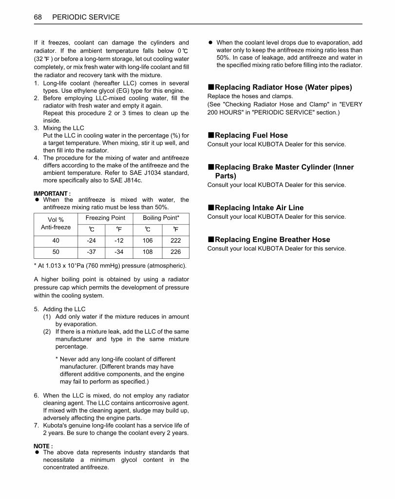
PERIODIC SERVICE68
If it freezes, coolant can damage the cylinders andradiator. If the ambient temperature falls below 0(32 ) or before a long-term storage, let out cooling watercompletely, or mix fresh water with long-life coolant and fillthe radiator and recovery tank with the mixture.1. Long-life coolant (hereafter LLC) comes in several
types. Use ethylene glycol (EG) type for this engine.2. Before employing LLC-mixed cooling water, fill the
radiator with fresh water and empty it again.Repeat this procedure 2 or 3 times to clean up theinside.
3. Mixing the LLCPut the LLC in cooling water in the percentage (%) fora target temperature. When mixing, stir it up well, andthen fill into the radiator.
4. The procedure for the mixing of water and antifreezediffers according to the make of the antifreeze and theambient temperature. Refer to SAE J1034 standard,more specifically also to SAE J814c.
A When the antifreeze is mixed with water, theantifreeze mixing ratio must be less than 50%.
* At 1.013 x 10 Pa (760 mmHg) pressure (atmospheric).
A higher boiling point is obtained by using a radiatorpressure cap which permits the development of pressurewithin the cooling system.
5. Adding the LLC(1) Add only water if the mixture reduces in amount
by evaporation.(2) If there is a mixture leak, add the LLC of the same
manufacturer and type in the same mixturepercentage.
6. When the LLC is mixed, do not employ any radiatorcleaning agent. The LLC contains anticorrosive agent.If mixed with the cleaning agent, sludge may build up,adversely affecting the engine parts.
7. Kubota's genuine long-life coolant has a service life of2 years. Be sure to change the coolant every 2 years.
A The above data represents industry standards thatnecessitate a minimum glycol content in theconcentrated antifreeze.
A When the coolant level drops due to evaporation, addwater only to keep the antifreeze mixing ratio less than50%. In case of leakage, add antifreeze and water inthe specified mixing ratio before filling into the radiator.
BReplacing Radiator Hose (Water pipes)Replace the hoses and clamps.(See "Checking Radiator Hose and Clamp" in "EVERY200 HOURS" in "PERIODIC SERVICE" section.)
BReplacing Fuel HoseConsult your local KUBOTA Dealer for this service.
BReplacing Brake Master Cylinder (Inner Parts)
Consult your local KUBOTA Dealer for this service.
BReplacing Intake Air LineConsult your local KUBOTA Dealer for this service.
BReplacing Engine Breather HoseConsult your local KUBOTA Dealer for this service.
Vol %Anti-freeze
Freezing Point Boiling Point*
40 -24 -12 106 222
50 -37 -34 108 226
* Never add any long-life coolant of different manufacturer. (Different brands may have different additive components, and the engine may fail to perform as specified.)
Downloaded from www.Manualslib.com manuals search engine
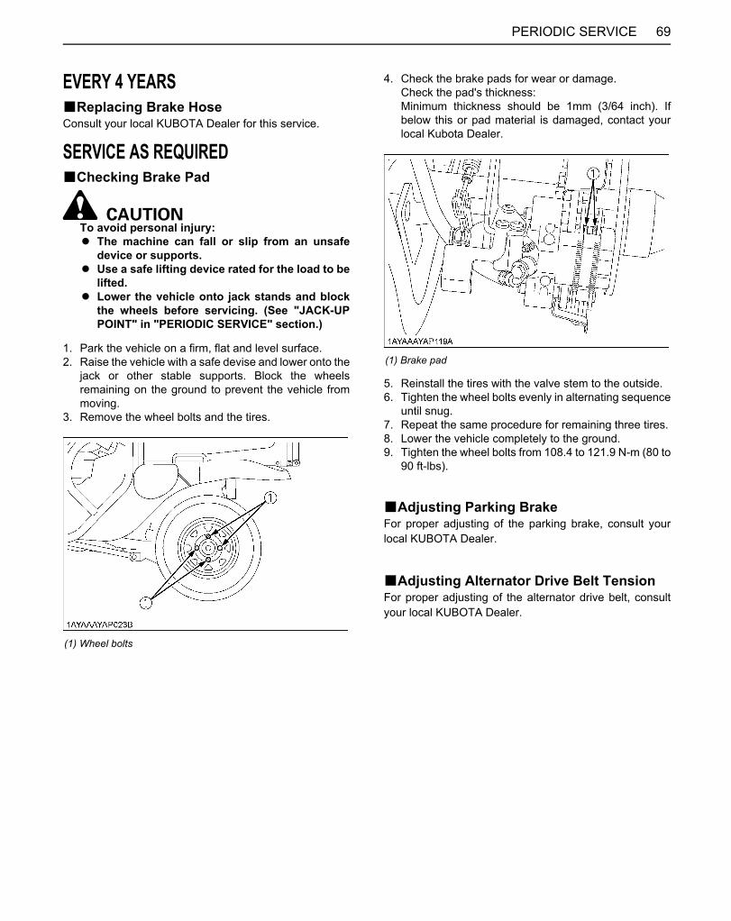
69PERIODIC SERVICE
EVERY 4 YEARSBReplacing Brake HoseConsult your local KUBOTA Dealer for this service.
SERVICE AS REQUIREDBChecking Brake Pad
To avoid personal injury:A The machine can fall or slip from an unsafe
device or supports.A Use a safe lifting device rated for the load to be
lifted.A Lower the vehicle onto jack stands and block
the wheels before servicing. (See "JACK-UPPOINT" in "PERIODIC SERVICE" section.)
1. Park the vehicle on a firm, flat and level surface.2. Raise the vehicle with a safe devise and lower onto the
jack or other stable supports. Block the wheelsremaining on the ground to prevent the vehicle frommoving.
3. Remove the wheel bolts and the tires.
4. Check the brake pads for wear or damage.Check the pad's thickness:Minimum thickness should be 1mm (3/64 inch). Ifbelow this or pad material is damaged, contact yourlocal Kubota Dealer.
5. Reinstall the tires with the valve stem to the outside.6. Tighten the wheel bolts evenly in alternating sequence
until snug.7. Repeat the same procedure for remaining three tires.8. Lower the vehicle completely to the ground.9. Tighten the wheel bolts from 108.4 to 121.9 N-m (80 to
90 ft-lbs).
BAdjusting Parking BrakeFor proper adjusting of the parking brake, consult yourlocal KUBOTA Dealer.
BAdjusting Alternator Drive Belt TensionFor proper adjusting of the alternator drive belt, consultyour local KUBOTA Dealer.
(1) Wheel bolts
(1) Brake pad
Downloaded from www.Manualslib.com manuals search engine

PERIODIC SERVICE70
BReplacing FuseThe vehicle electrical system is protected from potentialdamage by fuses.A blown fuse indicates that there is an overload or shortsomewhere in the electrical system.If any of the fuses should blow, replace with a new one ofthe same capacity.
A Before replacing a blown fuse, determine why the fuseblew and make any necessary repairs. Failure tofollow this procedure may result in serious damage tothe vehicle electrical system. Consult your localKUBOTA Dealer for specific information dealing withelectrical problems.
C Replacement procedure1. Disconnect the negative cable of the battery.2. Remove the cover and the fuse box cover.3. Pull out the blown fuse using FUSE PULLER in the
fuse box.4. Insert a new fuse into the fuse box.5. Install the fuse box cover.6. Connect the negative battery cable.
C How to distinguish between the old and new typeof the protected circuit
A Use the correct fuse label when replacing the fusecover.
C Protected circuit
(1) Fuse box
Fuse Label PART No. K7311-6128-1 K7311-6121-1 or later
Harness PART No. K7311-6120-4 or former K7311-6120-5 or later
Protected circuit OLD NEW
(1) Main harness(2) Harness part number label
FuseNo.
Capacity(A) Protected circuit (OLD) Protected circuit (NEW)
1 15 Head lamp, Tail lamp, Panel
2 10 Eng. control, Fuel pump Eng. control, Fuel pump, Fan motor relay
3 10 Cooling fan motor
4 20 Radiator Fan motor
5 15 (Hazard)
6 10 Alternator, Radiator fan relay, Cooling fan relay
Alternator, (Work light relay), (AUX (KEY ON))
7 5 Panel
8 10 12V DC output
9 15 Brake lamp, Horn
10 15 (Work light)
11 --- Fuse puller
12 5, 10, 15, 20
Spare
Downloaded from www.Manualslib.com manuals search engine

71PERIODIC SERVICE
BReplacing Slow-Blow FusesThe slow-blow fuses are intended to protect the electricalcabling. If any of them have blown out, be sure to pinpointthe cause. Never use any substitute, use only a KUBOTAgenuine part.
C Replacement procedure1. Disconnect the negative cable of the battery.2. Remove the cover and the slow-blow fuse box cover.3. Pull out the slow-blow fuse.4. Insert a new slow-blow fuse into the slow-blow fuse
box.5. Install the slow-blow fuse box cover.6. Connect the negative battery cable.
C Protected circuit
BReplacing Light Bulb1. Head lights
Take the bulb out of the light body and replace it witha new one.
2. Other lightsDetach the lens and replace the bulb.
(1) Slow-blow fuse box
Fuse No. Capacity (A) Protected circuit
1 Slow-blow fuse (50) Key switch
2 Slow-blow fuse (60) Alternator
Light Capacity
Head lights 27 W
Tail light 5 W
Brake light 21 W
Easy Checker(TM) 3.8 W (14V, 0.27A)
Instrument panel light 3.8 W (14V, 0.27A)
Downloaded from www.Manualslib.com manuals search engine

72 STORAGE
STORAGE
To avoid personal injury:A Do not clean the vehicle with engine running.A To avoid the danger of exhaust fume
poisoning, do not operate the engine in aclosed building without proper ventilation.
A When storing, remove the key from the keyswitch to avoid unauthorized persons fromoperating the vehicle and getting injured.
VEHICLE STORAGEIf you intend to store your vehicle for an extended periodof time, follow the procedures outlined below.These procedures will insure that the vehicle is ready tooperate with minimum preparation when it is removedfrom storage.1. Check the bolts and nuts for looseness, and tighten if
necessary.2. Apply grease to vehicle areas where bare metal will
rust also to pivot areas.3. Unload from cargo bed.4. Inflate the tires to a pressure a little higher than usual.5. Change the engine oil and run the engine to circulate
oil throughout the engine block and internal movingparts for about 5 minutes.
6. With all implements lowered to the ground, coat anyexposed hydraulic cylinder piston rods with grease (ifequipped).
7. Remove the battery from the vehicle. Store the batteryfollowing the battery storage procedures.(See "Checking Battery Condition" in "EVERY 100HOURS" in "PERIODIC SERVICE" section.)
8. Keep the vehicle in a dry place where the vehicle issheltered from the elements. Cover the vehicle.
9. Store the vehicle indoors in a dry area that is protectedfrom sunlight and excessive heat. If the vehicle mustbe stored outdoors, cover it with a waterprooftarpaulin.Put boards under the tires to keep dampness awayfrom tire.Keep the tires out of direct sunlight and extreme heat.
A When washing the vehicle, be sure to stop the engine.Allow sufficient time for the engine to cool beforewashing.
A Do not wash with a high-pressure car-washingmachine.
A Cover the vehicle after the muffler and the engine havecooled down.
REMOVING THE VEHICLE FROM STORAGE1. Check the tire air pressure and inflate the tires if they
are low.2. Install the battery. Before installing the battery, be sure
it is fully charged.3. Check the fan belt tension.4. Check all fluid levels (engine oil, transmission oil,
engine coolant and any attached implements).5. Check the spark plug gap. Install and tighten plugs to
the specified torque.6. Start the engine. Observe all gauges. If all gauges are
functioning properly and reading normal, move thevehicle outside. Once outside, park the vehicle and letthe engine idle for at least 5 minutes. Shut the engineoff and walk around vehicle and make a visualinspection looking for evidence of oil or water leaks.
7. With the engine fully warmed up, release the parkingbrake and test the brakes for proper adjustment as youmove forward. Adjust the brakes as necessary.
Downloaded from www.Manualslib.com manuals search engine

73TROUBLESHOOTING
TROUBLESHOOTINGENGINE TROUBLESHOOTINGIf something is wrong with the engine, refer to the table below for the cause and its corrective measure.
Trouble Cause Countermeasure
Engine is difficult to start or will not start.
A The range shift lever not in the properposition.
A Make sure the range shift lever is in"NEUTRAL" position.
A Key switch is not in the proper position. A Make sure key switch is in "ON"position.
A No fuel. A Replenish fuel.
A Improper or stale fuel.(Fuel quality is poor.)
A Replace fuel and consult yourKUBOTA Dealer.
A Water or dirt in the fuel system. A Replace fuel and consult yourKUBOTA Dealer.
A Fuel hose or fuel filter clogged ordamaged.
A Clean or replace fuel lines, and consultyour KUBOTA Dealer.
A Air cleaner is clogged. A Clean or replace the air cleanerelement.
A Spark plug defective. A Adjust the spark plug gap or replacethe spark plug.
A Check the spark plug wire connection.
A Fuse is blown. A Replace the fuse.
A Engine oil viscosity is wrong. A Use oils of different viscosities,depending on ambient temperature.
A Battery becomes weak and the enginedoes not turn over quick enough.
A Clean battery cables and terminals.
A Charge the battery.
A In cold weather, always remove thebattery from the engine, charge andstore it indoors. Install it on the machineonly when the machine is going to beused.
Insufficient engine power. A Insufficient or dirty fuel. A Check the fuel system.
A Air cleaner is clogged. A Clean or replace the air cleanerelement.
A Spark plug defective. A Adjust the spark plug gap or replace it.
Engine stops suddenly. A Insufficient fuel. A Refuel.
Downloaded from www.Manualslib.com manuals search engine

74 TROUBLESHOOTING
If you have any questions, consult your local KUBOTA Dealer.
Rough engine running. A Spark plug defective. A Adjust the spark plug gap or replace it.
A High tension cord defective. A Consult your KUBOTA Dealer.
A Ignition coil defective. A Consult your KUBOTA Dealer.
A Fuel hose or fuel filter clogged ordamaged.
A Clean or replace fuel lines, and consultyour KUBOTA Dealer.
A Improper or stale fuel.(Fuel quality is poor.)
A Replace fuel and consult yourKUBOTA Dealer.
A Air cleaner is clogged. A Clean or replace the air cleanerelement.
Exhaust fumes are colored.(Black, Dark or Gray)
A Overload. A Reduce load.
A Low grade fuel is used. A Use specified fuel.
A Air cleaner is clogged. A Clean or replace the air cleanerelement.
Exhaust fumes are colored.(White or Blue)
A Excessive engine oil. A Reduce to the specified oil level.
A Piston ring is worn or stuck. A Consult your KUBOTA Dealer.
Engine overheats. A Engine is overloaded. A Lower speed or reduce load.
A Engine oil is insufficient. A Replenish engine oil.
A Low coolant level. A Fill cooling system to the correct level;check radiator and hoses for looseconnections or leaks.
A The motor driven fan does not turn. A Check to see if the fuse is not blown.A Check the electric system.
A Dirty radiator core or grille screens. A Remove all trash.
A Coolant flow route corroded. A Flush cooling system.
Engine diagnostic light comes on. --- A Consult your KUBOTA Dealer.
Engine will not idle. A Spark plug defective. A Adjust the spark plug gap or replace it.
A Faulty spark plug. A Replace the spark plug.
Trouble Cause Countermeasure
Downloaded from www.Manualslib.com manuals search engine
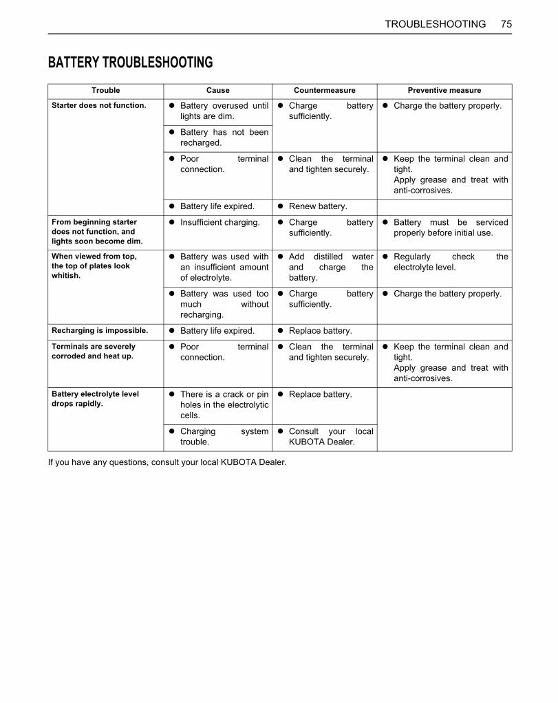
75TROUBLESHOOTING
BATTERY TROUBLESHOOTING
If you have any questions, consult your local KUBOTA Dealer.
Trouble Cause Countermeasure Preventive measure
Starter does not function. A Battery overused untillights are dim.
A Charge batterysufficiently.
A Charge the battery properly.
A Battery has not beenrecharged.
A Poor terminalconnection.
A Clean the terminaland tighten securely.
A Keep the terminal clean andtight.Apply grease and treat withanti-corrosives.
A Battery life expired. A Renew battery.
From beginning starterdoes not function, andlights soon become dim.
A Insufficient charging. A Charge batterysufficiently.
A Battery must be servicedproperly before initial use.
When viewed from top,the top of plates lookwhitish.
A Battery was used withan insufficient amountof electrolyte.
A Add distilled waterand charge thebattery.
A Regularly check theelectrolyte level.
A Battery was used toomuch withoutrecharging.
A Charge batterysufficiently.
A Charge the battery properly.
Recharging is impossible. A Battery life expired. A Replace battery.
Terminals are severelycorroded and heat up.
A Poor terminalconnection.
A Clean the terminaland tighten securely.
A Keep the terminal clean andtight.Apply grease and treat withanti-corrosives.
Battery electrolyte leveldrops rapidly.
A There is a crack or pinholes in the electrolyticcells.
A Replace battery.
A Charging systemtrouble.
A Consult your localKUBOTA Dealer.
Downloaded from www.Manualslib.com manuals search engine
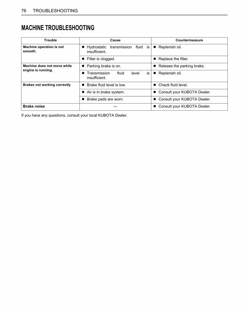
76 TROUBLESHOOTING
MACHINE TROUBLESHOOTING
If you have any questions, consult your local KUBOTA Dealer.
Trouble Cause Countermeasure
Machine operation is notsmooth.
A Hydrostatic transmission fluid isinsufficient.
A Replenish oil.
A Filter is clogged. A Replace the filter.
Machine does not move whileengine is running.
A Parking brake is on. A Release the parking brake.
A Transmission fluid level isinsufficient.
A Replenish oil.
Brakes not working correctly A Brake fluid level is low. A Check fluid level.
A Air is in brake system. A Consult your KUBOTA Dealer.
A Brake pads are worn. A Consult your KUBOTA Dealer.
Brake noise --- A Consult your KUBOTA Dealer.
Downloaded from www.Manualslib.com manuals search engine
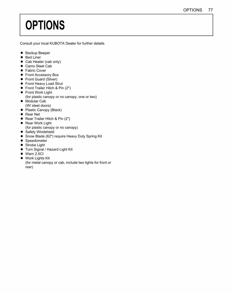
77OPTIONS
OPTIONSConsult your local KUBOTA Dealer for further details.
A Backup BeeperA Bed LinerA Cab Heater (cab only)A Camo Steel CabA Fabric CoverA Front Accessory BoxA Front Guard (Silver)A Front Heavy Load StrutA Front Trailer Hitch & Pin (2")A Front Work Light
(for plastic canopy or no canopy, one or two)A Modular Cab
(W/ steel doors)A Plastic Canopy (Black)A Rear NetA Rear Trailer Hitch & Pin (2")A Rear Work Light
(for plastic canopy or no canopy)A Safety WindshieldA Snow Blade (62") require Heavy Duty Spring KitA SpeedometerA Strobe LightA Turn Signal / Hazard Light KitA Warn 2.5CIA Work Lights Kit
(for metal canopy or cab, include two lights for front orrear)
Downloaded from www.Manualslib.com manuals search engine

78 ENGINE EMISSION RELATED INFORMATION
ENGINE EMISSION RELATED INFORMATIONC The GZ460F-E3 engine conforms to U.S. EPA and California emission regulations for off-road small SI engines.
A Emission compliance period: 1000 HOURSA CARB emissions durability period: EXTENDED
C Exhaust Emission Control SystemA Throttle Body Injection, Electronic Control Module, Three Way Catalyst
Downloaded from www.Manualslib.com manuals search engine