l author(s) j f 7. peroming organization …centrifugal compressor diffuser behavior and inlet...
TRANSCRIPT

MASTER CWT KEEP THIS COPY FOR REPRODUCTION PURPOSESC 1 VW F"A Approved
REPORT DOCUMENTATION PAGE I ,i No. 0704-01fi, ojoPublic "eo, ng burder, for this cowaictinf of information is iistlinale to av~aiii i how per retwoe. inciuding the time foe rewsew Ag instruction.. sarcfrig ex.,ti data 42um
a mtlm g d maintaning the data needed. and co0ieting and reviewing t•h1e4'10c in of ,Information Wnd com•inenrteg rdng th sburdfet mate or any otP(a.eecof thecoecIon of inlforlation. including 04 iotio for reducing this burden. to Wai•iCnton ofetadkuanteet Ttice• . Oere•torate rfor nformation 00eations andt Actior tinsDalsg4qhwayv. So•te 1204. Arlington. VA 222024302. and tO thetfKe Of Maneget t n ltg•. Paperwork ion fto P c1 (0704-01W). Winihoopo, DC 20S6 501. AGENCY USE ONLY (Lea1ve blank) i2. REPORT DATE I .REPTOITTYPE ANDDAECORD
,MI May 6, 199,4 I 0 _
_____ 4. TITLE AND SUBTITLE V. FUNDING NUMBIRS
Mt NUnsteady Flow Phenomena in Discrete Passage Diffusersfor Centrifugal Compressors 3
L AUTHOR(S)_
GoV. Filipenco, J.M. Johnston, E.M. Greitzer j f7. PEROMING ORGANIZATION NAME(S) AND ADORESSES) L L t. t- .P ING ORGANIZATION
I a UMBER
Gas Turbine Laboratory 9eMassachusetts Institute of Technology J 1F77 Massachusetts Ave. _Cambridge, MdA 02139 F
I.SONYNAME(S) AND ADRESS ............... JA. SPOINSORING /MONITORING
U. S. Army Research Office AGENCY REPORT NUMBER
P. 0. Box 12211Research Triangle Park, NC 27709-2211 P. 7• 6LD7. -•.-6-
11. SUPPLEMENTARY NOTESThe view, opinions and/or findings contained in this report are those of theauthor(s) and should not be construed as an official Department of the Armyposition, policy, or decision, unless so designated by other documentation.
12a. DISTRIBUTION /AVAILABILITY STATEMENT 12b. DISTRIBUTION CODE
Approved for public release; distribution unlimited.
o • 13. ABSTRACT (Maximum 200 words)
Wood=-_ EResearch is described on the fluid dynamic behavior of high performance diffusers for centrifugal
N compressors, with particular application to small gas turbine engine applications. Using a unique swirlgenerator, experiments have been carried out to define the performance and stall onset behavior of aT• modem discrete passage diffuser as a function of inlet conditions. Two diffusers were examined, one
with 30 passages and one with 38 passages. Inlet blockage and axial asymmetry were varied over Mach0 _ numbers up to unity and over a range of inlet swirl angles. Diffuser pressure recovery and operating
_• range were calculated using traverse measurements made upstream of the diffuser. It was found that theperformance of the diffuser under different inlet conditions could be expressed to a high degree ofaccuracy as a single curve of non-dimensional static pressure recovery coefficient, based on availability-averaged inlet stagnation pressure, and momentum-averaged inlet flow angle. Unsteady pressuremeasurements showed that the diffuser entered rotating stall at reduced flow rates. No long wavelengthstall precursor was determined from the measurements.
T94 7 12 143 MeQUALITSPECTD5
14. SUIUECT TERMS 15. NUMBER OF PAGES
Centrifugal compressor diffusers, discrete passage diffuser 37performance, centrifugal compressor stall l4 PRICE CODE
17. SECURITY CLASSIFICATION I 18. SECURITY CLASSIFICATION '19. SECURITY CLASSIFICATION 20. LIMITATION OF ABSTRACT
Of REPORT[ OF THIS PAGE OF ABSTRACT
UNCLASSIFIED UNCLASSIFIED UNCLASSIFIED UL,NSN 7S40-O1-280-500 Standard Form 298 (Rev. 2-89)
"Pricbed by ANSI Std Z3-.14198-l02

UNSTEADY FLOW PHENOMENAIN DISCRETE PASSAGE DIFFUSERS
FOR CENTRIFUGAL COMPRESSORS
FINAL REPORT
V. Filipenco, J.M. Johnston, E.M. Greitzer
Accesion For May 1994NTIS CRA&IDTIC TABUnannouncedJustification -..........
By ....................... U.S. Army Research OfficeDistribution I
Availability Codef.
Avail ai dIorSpecial Grant DAAL03-90-G-0138
Massachusetts Institute of TechnologyCambridge, MA 02139
APPROVED FOR PUBLIC RELEASE;DISTRIBUTION UNLIMITED.

UNSTEADY FLOW PHENOMENA IN DISCRETE PASSAGE DIFFUSERSFOR CENTRIFUGAL COMPRESSORS
- TABLE OF CONTENTS -
List of Tables and Figures 2Abstract 4Introduction and Problem Statement 4
Background 4Research Objectives 5
Experimental Apparatus 6Test Facility 6Radial Diffuser Geometry 6Instrumentation 7
Definition of Parameters 8Average Values .8Profile Descriptors 9
Blockage Definitions 9Test Plan 10Results I 1
Steady-State Data IIUnsteady Flow Phenomena 14
Summary and Conclusions 14Publications and Technical Reports 15Personnel 15References 16

2
LIST OF TABLES AND FIGURES
Table 1: Diffuser dimensions
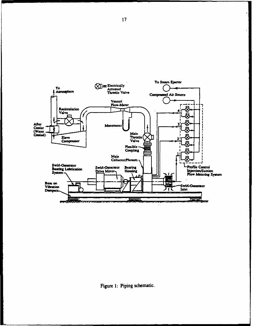
Figure 1: Piping schematic.
Figure 2: Swirl generator schematic.
Figure 3: Impeller blade shapes.
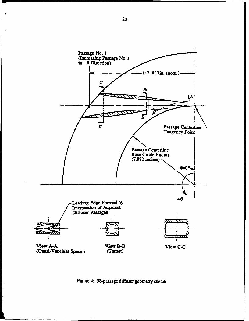
Figure 4: 38-passage diffuser geometry sketch.
Figure 5: Traverse Probe.
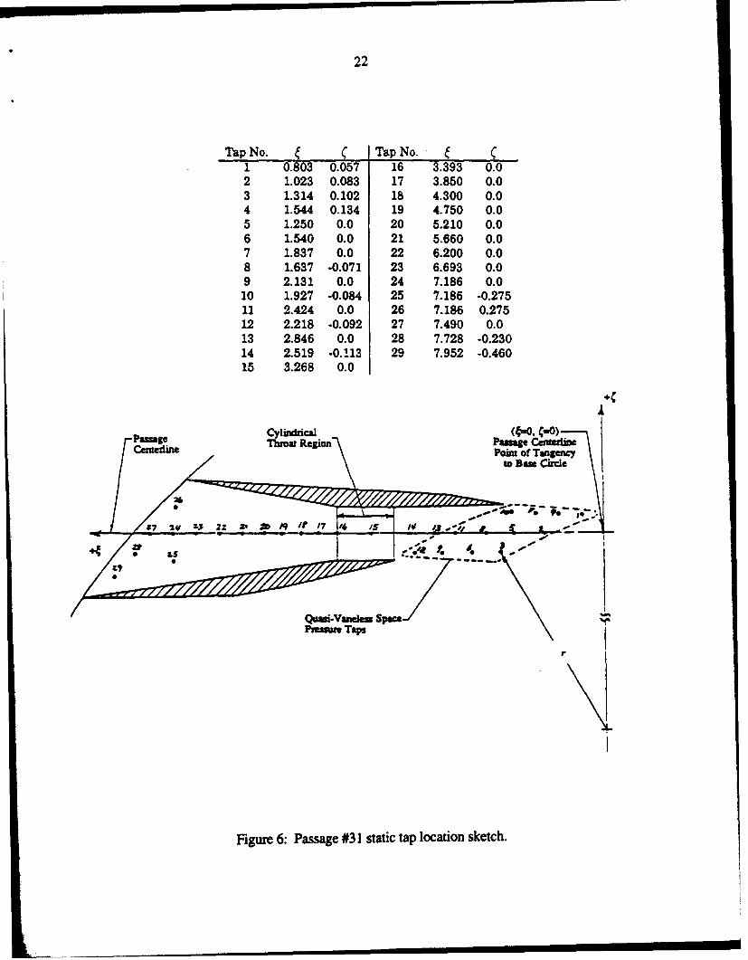
Figure 6: Passage #31 static tap location sketch.
Figure 7: Variation in inlet angle versus axial position at 4 KRPM for three cases:
0 no boundary layer control, 01 aft suction and forward injection,A forward suction and aft suction.
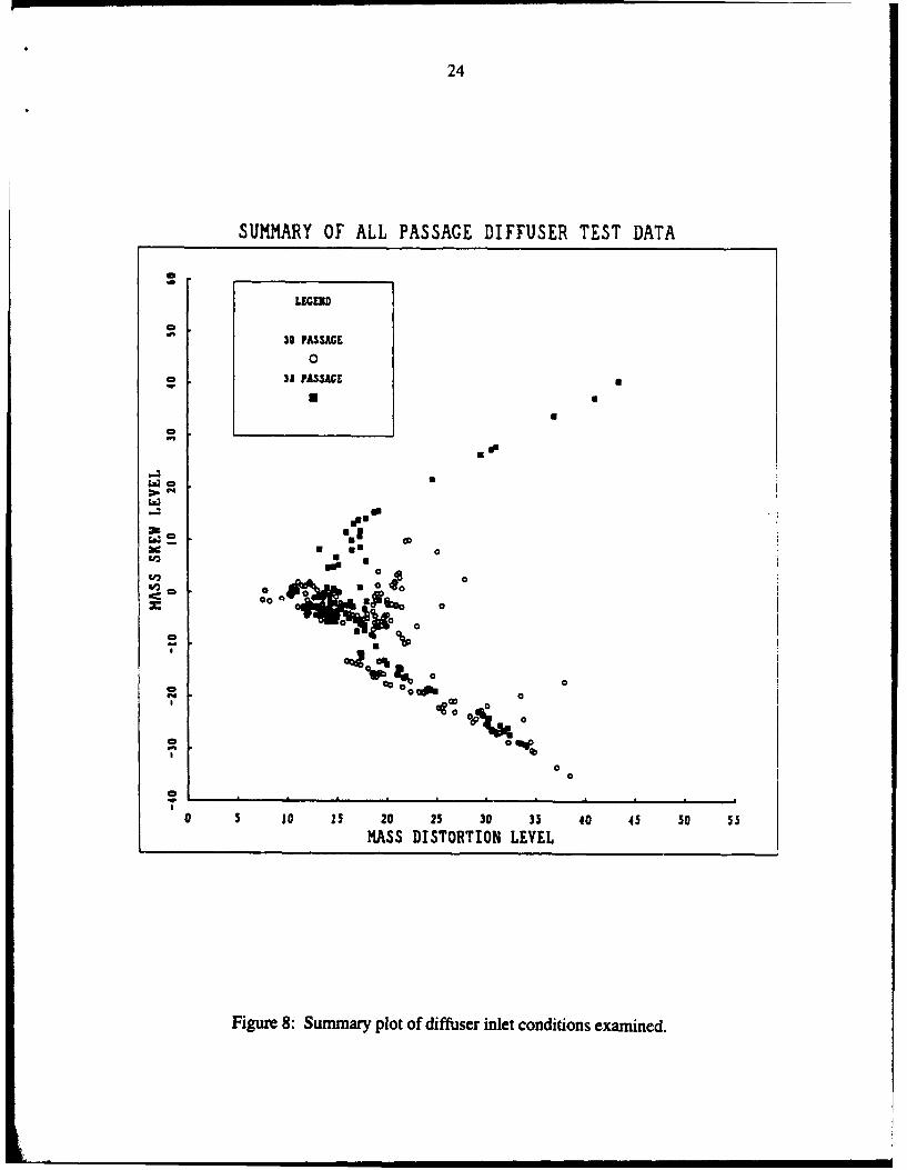
Figure 8: Summary plot of diffuser inlet conditions examined.
Figure 9: Flow conditions examined (38-passage diffuser): inlet swirl angle and inlet Machnumber combinations. Legend indicates speed and inlet control, where K = 1 KRPM,
inj = injection, suc = suction, FWD = shroud side (x/b = 1), and AFT = hub side
(x/b = 0).
Figure 10: Diffuser overall, availability-averaged pressure recovery, Cp,, as a function of
momentum-averaged inlet swirl angle (30-passage diffuser).
Figure 11: Near stall operating points, Cpy versus Ml for 38-passage diffuser. Legend indicates
speed and inlet control, where K = I KRPM, inj = injection, suc = suction, FWD =
shroud side (x/b = 1), and AFT = hub side (x/b = 0).
Figure 12: Pressure recovery coefficient at near stall points versus inlet mass flow distortion
parameter. Legend indicates speed and inlet control, where K = 1 KRPM, inj =
injection, suc = suction, FWD = shroud side (x/b = 1), and AFT = hub side (x/b = 0).
Figure 13: Pressure recovery coefficient at near stall points versus mass flow skew parameter.Legend indicates speed and inlet control, where K = 1 KRPM, inj = injection, suc =
suction, FWD = shroud side (x/b = 1), and AFT = hub side (x/b = 0).
Figure 14: Comparison of diffuser near stall CpW versus inlet Mach number for the 30-passage
and the 38-passage diffusers. Nominal inlet conditions are indicated by circles,
suction or injection is indicated by squares, and 38-passage data is indicated by shaded
symbols.

3
ElaUrM (cont.)
Figure 15: Comparison of near stall CpI versus inlet swirl angle for the 30-passage and the 38-
passage diffusers. Nominal inlet conditions are indicated by circles, suction or
injection is indicated by squares, and 38-passage data is indicated by shaded symbols.
Figure 16: A comparison of the estimated throat blockage and the inlet blockage.
Figure 17: Diffuser mass flow range with and without traverse probe.
Figure 18: Estimated 4 KRPM speed line pressure rise coefficient for nominal inlet conditions,
with and without traverse probe.
Figure 19: Nominal inlet, 4 KRPM high speed pressure data throttle to stall. Elapsed time was
one second. Normalized time, T, is tV0 1/2itrI.
Figure 20: Nominal inlet, no traverse probe, 4 KRPM at the operating point at which the diffuserstalls when the probe is installed. Normalized time, 't, is tlO/2irrI.
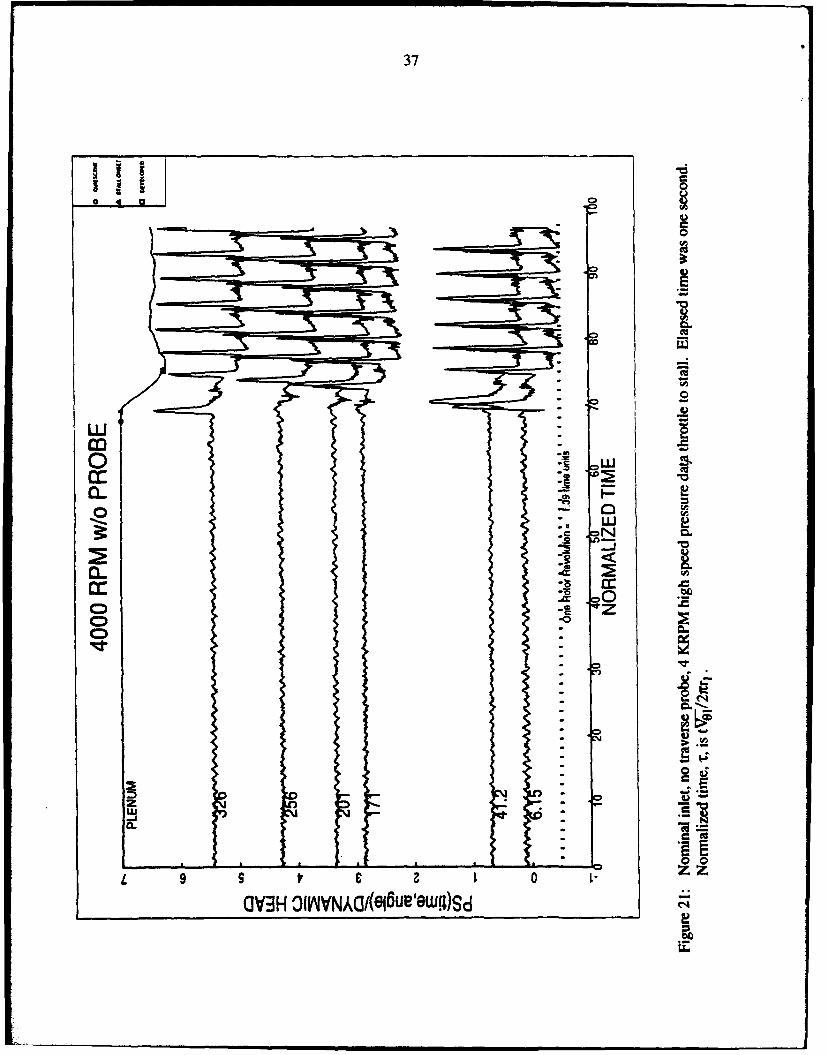
Figure 21: Nominal inlet, no traverse probe, 4 KRPM high speed pressure data throttle to stall.
Elapsed time was one second. Normalized time, ¶, is tV0 1/2= 1 .

4
ABSTRACT
Research is described on the fluid dynamic behavior of high performance diffusers for
centrifugal compressors, with particular application to small gas turbine engine applications.
Using a unique swirl generator, experiments have been carried out to define the performance and
stall onset behavior of a modern discrete passage diffuser as a function of inlet conditions. Two
diffusers were examined, one with 30 passages and one with 38 passages. Inlet blockage and axial
asymmetry were varied over Mach numbers up to unity and over a range of inlet swirl angles.
Diffuser pressure recovery and operating range were calculated using traverse measurements
made upstream of the diffuser. It was found that the performance of the diffuser under different
inlet conditions could be expressed to a high degree of accuracy as a single curve of non-
dimensional static pressure recovery coefficient, based on availability-averaged inlet stagnation
pressure, and momentum-averaged inlet flow angle. Unsteady pressure measurements showed
that the diffuser entered rotating stall at reduced flow rates. No long wavelength stall precursor
was determined from the measurements.
INTRODUCTION AND PROBLEM STATEMENT
This document represents the final report on research sponsored by the Army Research
Organization under Grant DAAL03-90-G-0138. The research addresses the fluid dynamic
behavior of high performance discrete passage diffusers for centrifugal compressors, with
particular application to small gas turbine engine applications. Experimental results are presented
for a 30-passage and a 38-passage diffuser designed at an aircraft engine company.
The diffuser of a high performance centrifugal compressor often limits the machine's
useful operating range due to the onset of aerodynamic instability, in the form of rotating stall or
surge, at mass flow rates below design. Measurement of flow conditions at the inlet to the diffuser
is difficult due to flow field sensitivity to instrumentation. The flow field of a centrifugal
compressor is thus typically measured at the impeller inlet and at the diffuser exit to provide

5
designers with information about the impeller-diffuser combination. These measurements,
however, do not isolate the individual component performances.
Defining the impeller and diffuser performance is desirable in design as well as when
trying to optimize a tested machine by redesign. This performance split is often estimated based
on some combination of static testing, calculated impeller and diffuser performances, and
performance of previous designs, but little data appears to exist which shows clearly the effect of
inlet conditions on diffusers. Testing a cascade passage diffuser in a manner in which the inlet
conditions can be controlled is difficult due to the transonic inlet Mach numbers and high swirl
angles characteristic of the impeller exit flow field. To address this problem, a test facility was
constructed which enables determination of diffuser performance up to near sonic conditions
(where the flow field is especially sensitive to instrumentation) and over a range of independently
variable inlet flow conditions.
The results of the investigation have been reported in depth in Refs. [I] and [2]. For this
reason the present report will not describe details of the design of the facility, nor give an extensive
compilation of the results of the experiments. Rather, we will present an overview of the facility
capability, and highlight the results which appear to be of most interest. The reader is referred to
[1] or [2] for additional material which supplements this report.
Reserch Objectives
One objective of the present study is to provide description of the causal links between
centrifugal compressor diffuser behavior and inlet conditions. A second is to characterize the
conditions that determine the limit of diffuser stable flow range. The variables of interest included
inlet Mach number, inlet angle, inlet mass flow distribution, and instrumentation blockage. A
third objective is to define the unsteady processes that are associated with the onset of instability
(rotating stall or surge) of the diffuser flow field.
6
EXPERIMENTAL APPARATUS
TetIaLt~a
The central elements of the test apparatus consists of a swirl generator which delivers an
axisymmetric swirling transonic flow into the test section where the radial diffuser is installed.
Reasons for the use of this method, as well as design goals, are given in Ref. [I]. The diffuser exit
flow is dumped to a plenum and routed to a slave compressor, which can be activated to lower the
diffuser back pressure. The overall scheme is depicted in Figure 1. The swirl generator, shown in
Figure 2, consists of an inlet, a negative reaction impeller composed of 71 high solidity blades
(Figure 3), a variable speed drive, and four slot rings for boundary layer control by mass injection
or suction. Both suction and injection may be applied in an axisymmetric manner upstream and
downstream of the impeller on either wall. The swirl generator operation envelope includes a
maximum average exit Mach number of unity, and a range of (momentum) average inlet swirl
angles up to 75 degrees.
In the description below, the axial direction is taken from the impeller hub, aft wall where
x = 0, to the shroud forward wall where x = b. The positive tangential direction is clockwise aft
looking forward, and zero degrees at top-dead-center. "Plane I" is the swirl generator exit radius,
which is the traverse probe radius. "Plane 2" is the diffuser exit radius upstream of the dump to
the plenum. "Plane IA" is the radius defined by the diffuser inlet circumferential static taps.
"Plane 0" is the impeller exit. All other planes are explicitly called out.
Radia Diffuser Gi metry
There are four contiguous parts of the tested passage diffusers: the quasi-vaneless space,
the throat, the diffuser, and the dump. Passage diffusers are defined along a centerline that is
inclined at a large angle from a radial line. The quasi-vaneless space, which is designed to diffuse
supersonic flow, is defined by the scalloped leading edges which span the passage width on either
side of the passage (see Figure 4). The area converges to the throat, which fixes the maximum
flow rate through the diffuser. The throat section is a cylinder with a length approximately equal to
7
its radius. Downstream of the throat, there is an expanding section which is a partial cone; the
cone is cut by the two walls of diffuser which linearly diverge from the throat to the exit. The
diffuser is thus a mix between a conical and a two dimensional diffuser, where most (over 85%
for the 38-passage diffuser) of the area increase occurs in the tangential direction about the passage
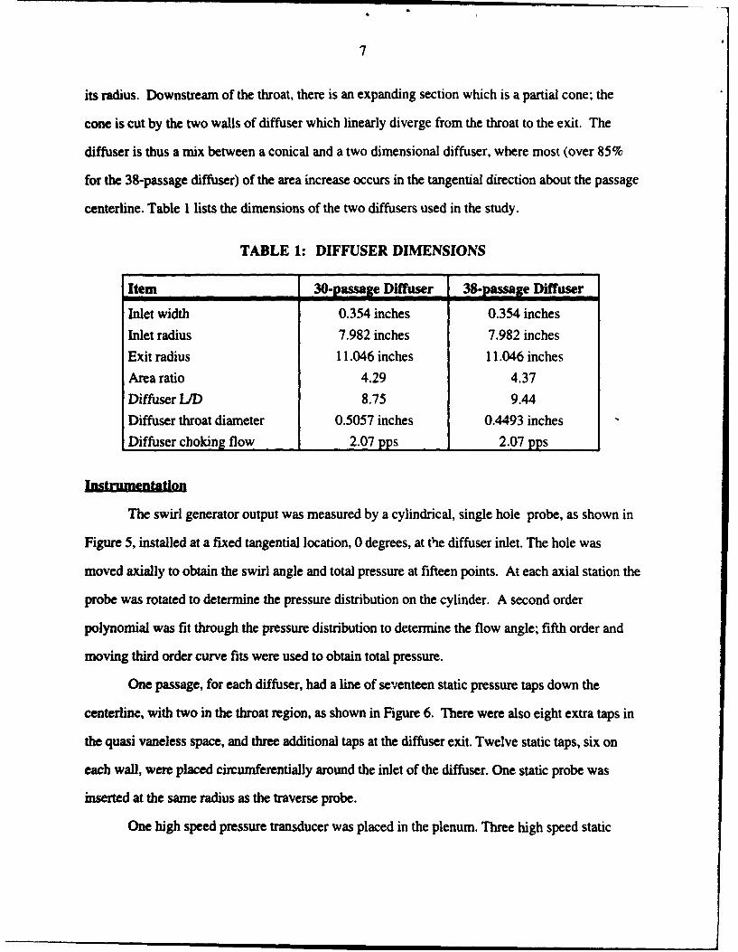
centerline. Table 1 lists the dimensions of the two diffusers used in the study.
TABLE 1: DIFFUSER DIMENSIONS
Item 30-passage Diffuser 38-passage Diffuser
Inlet width 0.354 inches 0.354 inches
Inlet radius 7.982 inches 7.982 inches
Exit radius 11.046 inches 11.046 inches
Area ratio 4.29 4.37
Diffuser L/D 8.75 9.44
Diffuser throat diameter 0.5057 inches 0.4493 inches
Diffuser choking flow 2.07 pps 2.07 pps
Instrumentation
The swirl generator output was measured by a cylindrical, single hole probe, as shown in
Figure 5, installed at a fixed tangential location, 0 degrees, at the diffuser inlet. The hole was
moved axially to obtain the swirl angle and total pressure at fifteen points. At each axial station the
probe was rotated to determine the pressure distribution on the cylinder. A second order
polynomial was fit through the pressure distribution to determine the flow angle; fifth order and
moving third order curve fits were used to obtain total pressure.
One passage, for each diffuser, had a line of seventeen static pressure taps down the
centerline, with two in the throat region, as shown in Figure 6. There were also eight extra taps in
the quasi vaneless space, and three additional taps at the diffuser exit. Twelve static taps, six on
each wall, were placed circurnferentially around the inlet of the diffuser. One static probe was
inserted at the same radius as the traverse probe.
One high speed pressure transducer was placed in the plenum. Three high speed static
8
pressure transducers were installed in the vaneless space ring for the 30-passage diffuser testing.
Five more were added for the 38-passage diffuser testing, although two of the original set were
found to be inoperative.
The temperature was measured near the facility inlet screen and at one location in the
plenum. A downstream venturi was used to measure mass flow.
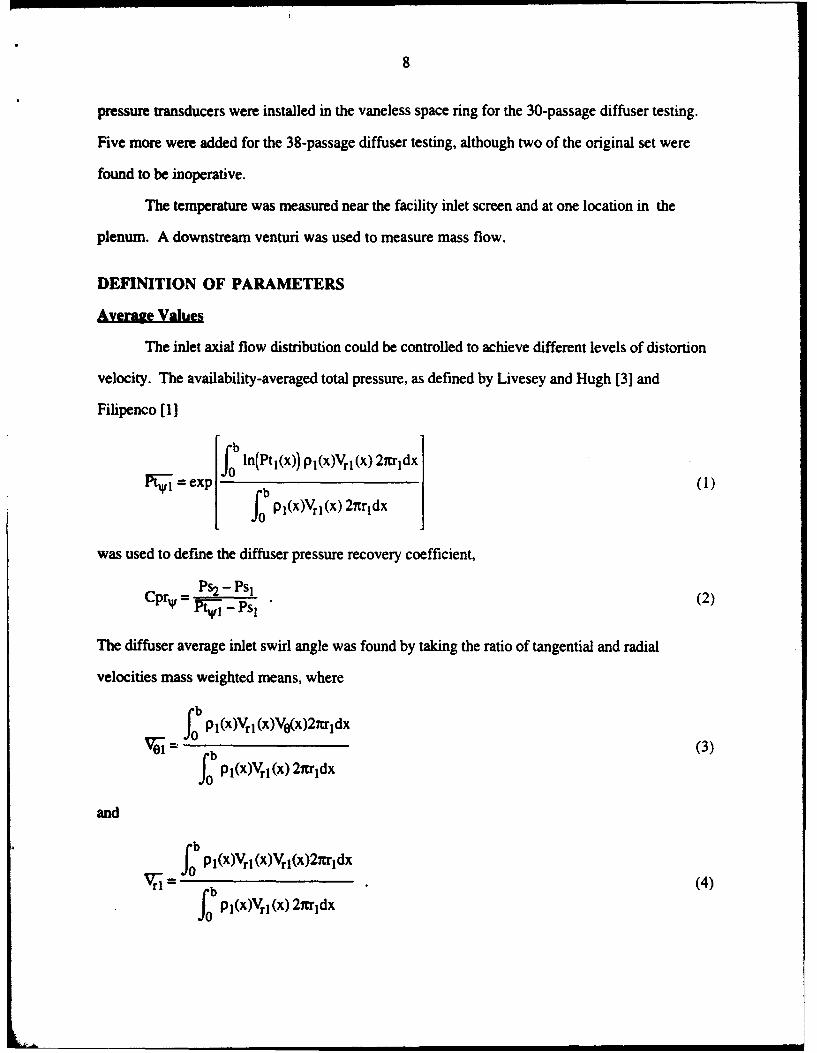
DEFINITION OF PARAMETERS
Average Values
The inlet axial flow distribution could be controlled to achieve different levels of distortion
velocity. The availability-averaged total pressure, as defined by Livesey and Hugh [3] and
Filipenco [1]
.. ep f ln(PtlI(x)) plI(X)Vr I (x) 27cr'ldX()
L b p 1 (x)Vrl (x) 27Er
ldx
was used to define the diffuser pressure recovery coefficient,
Cpr, = Ps2 - Psi(2)lV• - PSI(2
The diffuser average inlet swirl angle was found by taking the ratio of tangential and radial
velocities mass weighted means, where
Lb1f Pl(x)Vrl (x)V0(x)27Irrdx
ve-=(()fob PI(x)Vr1(x)27rrldx
and
rbJf pl(x)VrM (x)Vrl(x)2='idx
S= (4)fob Pi()X)V (x) 2igrldX
9
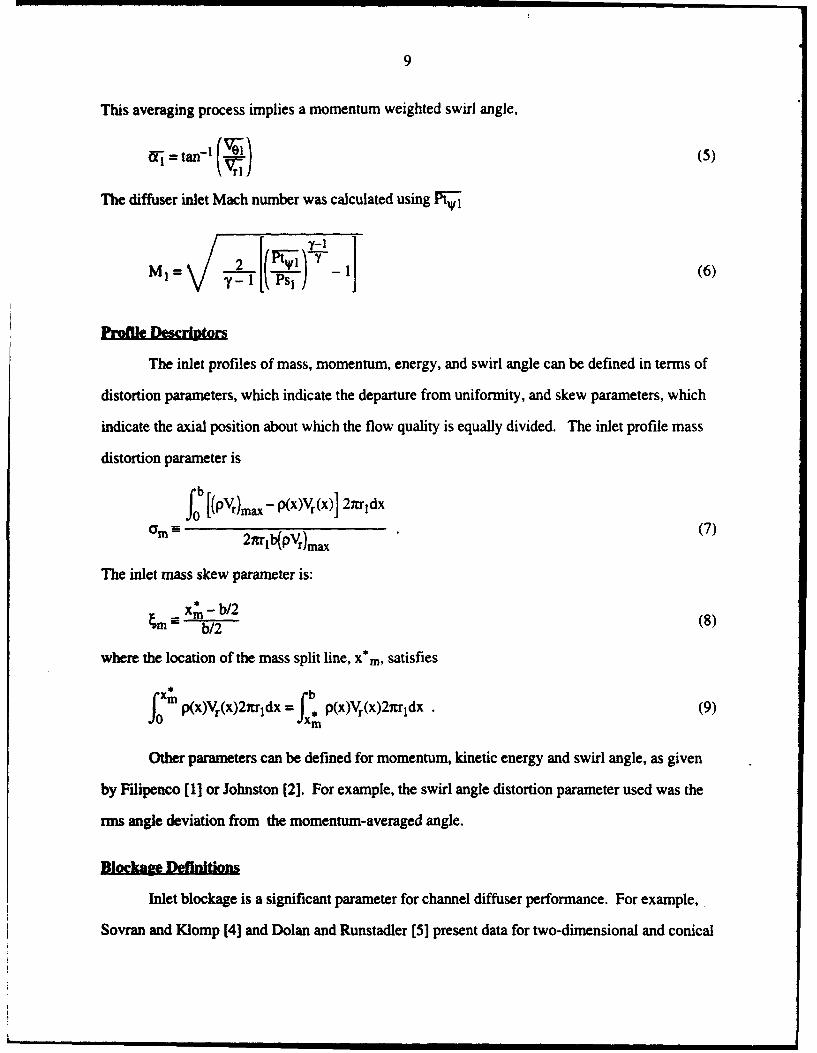
This averaging process implies a momentum weighted swirl angle,
The diffuser inlet Mach number was calculated using F.
Profte Descriptor
The inlet profiles of mass, momentum, energy, and swirl angle can be defined in terms of
distortion parameters, which indicate the departure from uniformity, and skew parameters, which
indicate the axial position about which the flow quality is equally divided. The inlet profile mass
distortion parameter is
fb [(Pv) - P(X)Vr{x] 2=crldx
m= - 2xrjb(PVr)max (7)
The inlet mass skew parameter is:
m x - b/2 ib/2 (8)
where the location of the mass split line, x'm, satisfies
p(x)Vr(x)27tridx= p(xY¶,(x)2rrddx .(9)
Other parameters can be defined for momentum, kinetic energy and swirl angle, as given
by Filipenco [1] or Johnston [2]. For example, the swirl angle distortion parameter used was the
rms angle deviation from the momentum-averaged angle.
Blockage Definitions
Inlet blockage is a significant parameter for channel diffuser performance. For example,
Sovran and Klomp [4] and Dolan and Runstadler [5] present data for two-dimensional and conical

10
diffusers which show decreasing diffuser static pressure coefficient with increasing boundary layer
blockage at the diffuser inlet. In the present experiment, the boundary layer thickness is measured
at the passage diffuser quasi-vaneless space inlet, not at the inlet of the channel part of the diffuser.
In addition, for off-design high incidence cases, the boundary layer blockage associated with the
flow around the scalloped leading edge may have a strong effect on overall diffuser performance.
As given by Dolan and Runstadler [5], the throat blockage is defined as
B = 1 (lThaca)al (10)( mideal )throat*
The throat blockage is not directly measured by this experiment. The actual mass flow is
measured by the venturi. The ideal mass flow can be estimated as
ie /T PtIAl MICosa(1mhideaI V RI T2 2y+1
The blockage at the quasi-vaneless space inlet is based on the mass flow from Eq. (11) using the
availability-averaged total pressure (instead of the upstream reservoir total pressure used by Dolan
and Runstadler). In addition, it is assumed that the flow is isentropic from the inlet to the throat,
that the throat static pressure is equal to the lower of the two measured throat static pressures, and
that the flow is essentially uni-directional at the throat.
TEST PLAN
A series of constant corrected speed data sets (speed lines) were obtained for both
diffusers. Boundary layer control was used to vary distortion parameter levels. Representative
inlet swirl angle profiles for the no boundary layer control case and for two high skew cases are
shown in Figure 7. The corresponding absolute Mach number profiles are also different from
each other because the Mach number decreases as the swirl angle increases. The 30-passage
diffuser testing had negative skew profiles, while the 38-passage diffuser testing included both
positive and negative skews. A view of the range of inlet conditions is given in Figure 8 which
shows the mass skew parameter as a function of mass distortion parameter for all data points, and
in Figure 9 (for the 38-passage diffuser) which shows the flow angle versus Mach number
operating points for different suction and injection conditions. Each speed line consisted of a
number of steady state operating points from choke to stall, including a near stall point. Three
corrected speeds were examined: 2 KRPM, 4 KRPM, and 6 KRPM. Stall was detected by
observing the output of one high speed pressure transducer, but it was also quite evident from
decreased venturi mass flow and the plenum blow down. At the conclusion of the 38-passage
diffuser test the traverse probe was removed and the 4 KIRPM nominal and high distortion profiles
speed lines were repeated. Unsteady data was measured without boundary layer control at several
corrected speeds. Data was taken with and without the traverse probe being installed.
The flow delivered by the swirl generator was axisymmetric to a high degree. The inlet
static pressure circumferential variation was typically less than 2% of the dynamic pressure,
_ pV2, with the most variation being 4%. The two independent measurements of mass flow, the
downstream venturi mass flow and the integrated inlet profile mass flow, agreed to within 5% for
both diffuser tests; it may be noted that 0.5 degree error in the traverse angle would change the
integrated inlet mass flow by 3.3% for a near stall swirl angle.
By applying suction aft of the impeller, it was possible to move the relative operating
points of the diffuser and impeller separately. This technique was used to determine that it was the
diffuser that initially encountered stall instability.
RESULTS
Steady-State Data
As discussed by Filipenco [1], a diffuser pressure recovery based on a dynamic pressure
that used the availability total pressure provided a more general measure of diffuser performance
than alternate dynamic pressure definitions (e.g. dynamic pressures based on the peak profile total
pressure, area-averaged total pressure, or area-averaged velocity). At stall, the availability total
pressure based diffuser recovery, CprW , decreased from 0.72 to 0.68 as the Mach number was
increased from 0.15 to 0.80 under nominal conditions for the 30-passage diffuser, and to 0.67 at a

12
Mach number of 0.95.
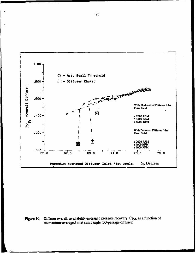
Pressure recovery coefficients versus the inlet swirl angle for six speed lines, three without
distortion and three with high distortion, are shown in Figure 10 The differences in speed
(equivalent to Mach number) and profile distortion are collapsed by using the pressure coefficient
based on availability total pressure; alternative definitions of recovery would lead to diffuser
performance that varied versus speed and inlet distortion.
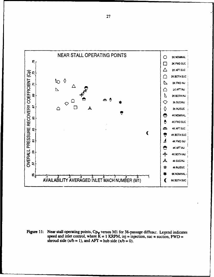
Pressure recovery coefficients for 20 near stall points with the 38-passage diffuser are
shown as a function of inlet Mach number in Figure 11. (Note the expanded scales.) The diffuser
pressure recovery coefficient decreases as the Mach number increases. No corresponding trend is
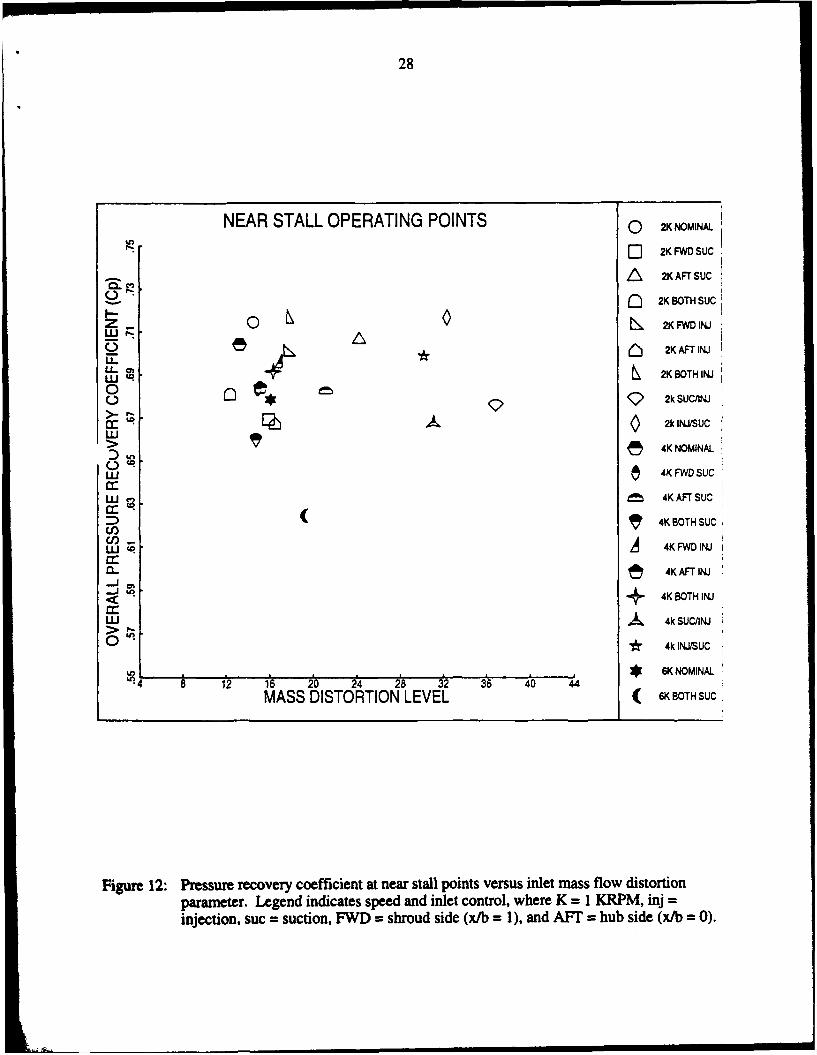
observed for diffuser performance versus inlet mass distortion parameter, as shown in Figure 12.
There is a weak trend of decreasing diffuser performance as the mass is skewed towards the
impeller shroud, as given in Figure 13. In Figure 13, there are six pairs of points which comprise
near stall points, at similar Mach number and inlet distortion parameter levels, which feature mass
distributions that are reflected about the diffuser axial centerline, x/b = 0.5. Five of the six pairs
indicate that when the mass distribution is skewed towards the impeller shroud, the diffuser does
not perform as well. The one exception is where the near stall point for the negative skew case
was not as close to stall, in terms of throttle closure, as the positive skew case. The extreme pairs,
where suction and injection are applied, at 2 KRPM and 4 KRPM best illustrate the trend. The
total data set of near stall points is shown in Figures 14 and 15 for both diffusers; the same general
trends are exhibited for both.
The question of why diffuser performance is not sensitive to inlet distortion parameter is an
issue of interest. The relation between the (caJculated) blockage at the throat and the inlet mass
distortion parameter is definitively not a strong one, particularly at off-design, as shown in Figure
16. We are currently examining this point; the idea is to "separate" the diffusion up to the throat
from the diffusion downstream of the throat viewing the latter as similar to a channel diffuser.
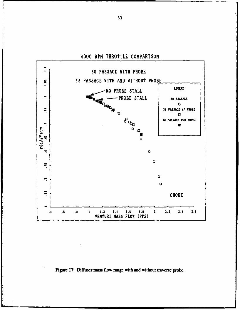
Removing the traverse probe had a large effect on stall onset point. Near stall, axial motion
of the traverse cylinder caused the diffuser to stall on repeated occasions. Typically, a near stall

13
operating point was set and the machine allowed to stabilize. The test sequence would begin and
the traverse would start to move axially with the consequence that the diffuser would enter rotating
stall immediately after the probe moved. To determine the effect of the circumferential distortion
created by the traverse cylinder upon diffuser stall margin, the probe was removed and 4 KRPM
speed lines with nominal inlet and both extreme skews were measured.
Without the traverse there is some uncertainty in determining the extent of inlet distortion
for the skewed inlet distributions. Comparisons between the nominal inlet operating points are
thus more meaningful but the mass flow operating range for both high skew cases increased by
approximately 10% when the probe was not installed.
Removing the traverse probe increased the mass flow range by 15%, with the nominal inlet
profile. Figure 17 shows the average diffuser inlet static pressure at plane IA versus venturi mass
flow for the 4 KRPM throttle for three cases: 30-passage diffuser with the traverse probe installed,
38-passage diffuser with the traverse probe installed, and 38-passage diffuser without the traverse
probe installed.
No direct data is available for the 30-passage diffuser performance without the traverse
probe. Only the throttle positions and the plane I static pressures are available, but these do indicate
a similar mass flow range increase. At 4 KRPM, both diffusers stalled at a plane I pressure ratio
of 0.985 with the traverse installed and both stalled at a plane I pressure ratio of 1.0 without the
probe installed.
Indirect evidence is furnished from the 30-passage diffuser data taken with a bent traverse
probe (i.e., larger blockage). The stalling flow for this configuration is estimated to be 30% higher
than for the configuration without the probe (at a plane 1 pressure ratio of 0.95). The implication
is that the diffuser may be more sensitive to steady circumferential distortion than to axial
distortion.
Based on the measured swirl generator performance, the relationship of pressure recovery
to venturi mass flow can be derived assuming that the flow in the vaneless space is isentropic.
Utilizing this approach, the pressure recovery of the diffuser was estimated for the nominal inlet
14
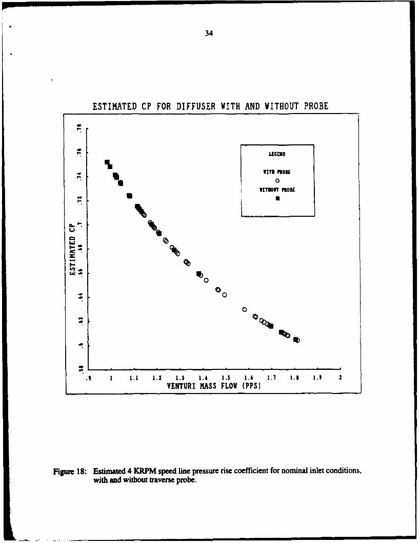
operating points taken without the traverse probe installed, as shown in Figure 18. There is a 0.04
difference in pressure recovery, which is significant when viewed in terms of the length increase
needed to obtain the same increase in peak recovery. A six degree conical diffuser with a peak
pressure recovery coefficient of 0.71 would have to be 63% longer to reach the 0.75 pressure
recovery level (Ref. [5] Figure 56, Mach number = 0.4, throat blockage = 0.03).
Unstead Flow Phenomena
Unsteady measurements were also taken to define the phenomena at stall onset.
Intermittent small amplitude, long wavelength activity was observed before stall with no traverse
probe installed. These waves moved in the opposite sense to the impeller rotation and the rotating
stall waves. No coherent activity was evident prior to stall when the probe was installed, as seen in
a typical time trace shown in Figure 19. The rotating stall instability was always first observed in
the quadrant immediately in the direction of impeller rotation "downstrem" of the probe. Prior to
stall, the static pressure variations in this region were larger than in the other three quadrants.
Removal of the probe eliminated the probe noise at the same throttle setting, as seen in Figure 20.
With no probe, there was coherent activity on an intermittent basis prior to stall, as seen in Figure
21. Most of the energy was in the first and second mode, and appeared near the impeller rotation
frequency. The inception process was short in duration, lasting about five rotor revolution times
from first observation to essentially fully developed.
SUMMARY AND CONCLUSIONS
A facility has been designed and constructed for examination of diffusers for high
performance centrifugal compressors. The facility provides a transonic swirling flow at diffuser
inlet, with control of inlet velocity profiles. Using this facility, the fluid dynamic behavior of two
modem discrete passage diffusers has been assessed with primary focus on the effect of inlet
conditions.
Definition of a pressure rise coefficient using an availability-averaged total pressure
provided a generalized view of diffuser data for different Mach numbers and inlet distortion. The
15
mass-averaged total pressure was close to the availability-averaged total pressure, but area-
averaged total pressure was quite different, i.e. Cpr4 S Cprmass * Cprarea .
There appears to be little relation between blockage, or mass distortion parameter, at the
quasi-vaneless space inlet to the throat blockage. Efforts are now ongoing to define the relation
between inlet quantities and the throat blockage; the latter is viewed as the main factor in the
channel diffuser performance.
The effect of the probe on the stall onset implies that the stalls with the probe inserted are
due to the probe wake. (The probe blockage is roughly 10% in terms of the probe cross-s
area compared to the 38-passage diffuser throat area. Once the probe was removed the operational
range increased and the stall mechanism changed.
No periodic activity was measured at the throttle setting where the diffuser stalled when
the probe was inserted. As the throttle was closed, small amplitude, intermittent waves travelled in
the opposite direction to impeller rotation were detected. Rotating stall inception occurred quickly,
within five impeller revolutions of first evidence.
PUBLICATIONS AND TECHNICAL REPORTS
Filipenco, V., "Experimental Investigation of Flow Distortion Effects on the Performance ofRadial Discrete-Passage Diffusers," MIT Gas Turbine Laboratory Report No. 206, September1991.
Johnston, J.M., "Stall Onset Observations of a Discrete Passage Diffuser," MIT Gas TurbineLaboratory Report No. 217, March 1993.
PERSONNEL
E.M. GreitzerV. Filipenco (Ph.D. Thesis)J.M. Johnston (M.S. Thesis)Y.C. Liang (M.S. Thesis expected 6/94)
16
REFERENCES
1. Filipenco, V., "Experimental Investigation of Flow Distortion Effects on the Performance ofRadial Discrete-Passage Diffusers," MIT Gas Turbine Laboratory Report No. 206,September 1991.
2. Johnston, J.M., "Stall Onset Observations of a Discrete Passage Diffuser," MIT Gas TurbineLaboratory Report No. 217, March 1993.
3. Livesey, J.L., Hugh, T., "'Suitable Mean Values' in One-Dimensional Gas Dynamics,"Journal Mechanical Engineering Science, Vol. 8, No. 4, 1966.
4. Sovran, G., Klomp, E.D., "Experimentally Determined Optimum Geometries for RectilinearDiffusers with Rectangular, Conical, or Annular Cross Section," in Fluid Mechanics ofInternal Flows, G. Sovran, Ed., Elsevier, 1967.
5. Dolan, F.X., Runstadler, P.W., Jr., "Pressure Recovery Performance of Conical Diffusers atHigh Subsonic Mach Numbers," NASA Technical Report CR-2299, August 1973.
17
To ElctriallyTo Steam Ejector
Throttle Valve CrposdArSuc
Afte-Mete
Cool"r(Water
Cooed Mailn iern Sse
Figure 1:oPping shmtc

18
Testar Snjeconionio
nstreamn Injection/Suction
/ Injection/Suction
Rotating-Iolet
Figureur 2:atn Swrlgneaorsceatc

19
NB= • s1
Figure 3: Impeller blade shapes.
20
Passage Cent.lin
~ ~S(Icraaing Passge Fooed.y'sin +6 DirectiofAjcnt
Difoe Paaagesages~i
(Quasi-Vaassage Space)eThroae
Figur4:8-pasagediffser geomletr Rkedih.

21
Discrete PassageDiffuser
Sensing Hole,Probe Body, 0.0091 Inches0.039 Inches dia. (nom.)dia. (nora.) " To Pressure
(. '. Transducer
From Swirl GeneratorRotorI
Vaneless Space Width-0.354 inches (nora.)
Figure 5: Traverse Probe.
22
Tap No. • ( Tap No. '1 0.803 0.057 16 3.393 0.02 1.023 0.083 17 3.850 0.03 1.314 0.102 18 4.300 0.04 1.544 0.134 19 4.750 0.05 1.250 0.0 20 5.210 0.06 1.540 0.0 21 5.660 0.07 1.837 0.0 22 6.200 0.08 1.637 -0.071 23 6.693 0.09 2.131 0.0 24 7.186 0.010 1.927 -0.084 25 7.186 -0.27511 2.424 0.0 26 7.186 0.27512 2.218 -0.092 27 7.490 0.013 2.846 0.0 28 7.728 -0.23014 2.519 -0.113 29 7.952 -0.46015 3.268 0.0
Tivoit Regon Poim of Tangency
IsIPaumr Tap$
Figure 6: Passage #31 static tap location sketch.

23
SWIRL ANGLE VARIATION DUE TO DISTORTION4000 RPM NEAR STALL OPERATING POINTS
AVG.
0
w ANGLE
z
a:
3 -& 74.58(I-
__ 0-ZN
( 73.99
NORMALIZED AXIAL DISTNCE (x/b)
Figure 7: Variation in inlet angle versus axial position at 4 KRPM for three cases:0 no boundary layer control, 0 aft suction and forward injection,Sforward suction and aft suction.
24
SUMMARY OF ALL PASSAGE DIFFUSER TEST DATA
LEGEND
30 PASSAGE
0
C ~38 PASSAGE
4 C
CD 0 o a s 2 s • 5 0 4 o
0
0G
w 00
0W
0 5 to i5 20 25 30 35 40 45 so 55MASS DISTORTION LEVEL
Figure 8: Summary plot of diffuser inlet conditions examined.

25
INLET SWIRL ANGLE AND MACH NUMBER FOR ALL SPEED LINES 2 K NOMINAL
PE 3 2K FWD SUC
t -•-2K AFT SLIC• 8= ' "A •aosuc
(D- 2K BOTHSUC
•rJ 4%, 2(FWD INJ0
z 2K AFr INJ<(
-U 2K BOTH INJ
0 • 4k SUC'INJ
t5 4k INJISUC
r,-~~~4 *, ,= NOMINAL
AVAILABILITY AVERAGED INLET MACH NUMBER (M1) ( 4KOAFTSUC
Figure 9: Flow conditions examined (38-passage diffuser): inlet swirl angle and inlet Machnumber combinations. Legend indicates speed and inlet control, where K = 1 KRPM,min = injection, suc = suction, FWD = shroud side (x/b = 1), and AFT = hub side(xb = o).
26
± .00-
0 " Rot. Stall Threshold
.800- - Diffuser Choked
*0
-' .6oo- -
"With Undistorted Diffuser Inlet
C_ ..y Flow Field
O .400 a x 2000 RPM
0 • 4000 RPM+ 6000 RPM
With Distorted Diffuser Inlet.200- Flow Field
1+1 o 2000 RPMs 4000 RPM
,00 z 6000 RPM
65.0 67.0 59.0 71.0 73.0 75.0
Momentum Averaged Diffuser Inlet Flow Angle. 01 , Degrees
Figure 10: Diffuser overall, availability-averaged pressure recovery, Cpl, as a function ofmomentum-averaged inlet swirl angle (30-passage diffuser).
27
NEAR STALL OPERATING POINTS o 2KNOMINAL.
" 2K FWD SUC
A 2K AFrsuc
-- • 2K BOTH SUC
I-z 2K FWDINW
WvA-) kK AFT INJ
.L 22KBOTH INJ
O * 9 2k SU/IN.J
x ~2k IN.SUC> 15 •4K NOMINAL
!L1 4KFWDSUC
LU Ch• 4K AFT SUC
( , 4K BOTHSUCco
J 4K AFTIWNJCC
J 4K BOTH INJ
wJ A, 4k SUC/INJ
O * 4kI&JISUC
,I 6SK NOMINAL-.0 .4 .5 . 7 .8 .9 1
AVAILABILITY AVERAGED INLET MACH NUMBER (Ml) ( BOTH SUC
Figure 11: Near stall operating points, CpW versus M1 for 38-passage diffuse,,. Legend indicatesspeed and inlet control, where K = 1 KRPM, inj = injection, suc = suction, FWD =shroud side (x/b = 1), and AFT - hub side (x/b = 0).
28
NEAR STALL OPERATING POINTS o 2KNOMINAL
Q 2K FWD SUC
/A 2K AFT SUC
C) 2K BOTH SUC
UI- 0 K•AFWTINJ
LU 2K BOTH INJ
0 Qe2k SUC11
LUI> _5 4K NOMINAL
LU 4K FWD SUC
S1' 4K AFT SUC
(" (4KBOTHSUCCf,•;.A 4K FwDINJ
CL 4K AFTIN&
S• + 4K BOTH INJ
LU U 4k SUCIINJ
* 4kINJsUC
____________O___________ 6K 6NOMINAL4 12 116 20 24 28 32 36 40 44
MASS DISTORTION LEVEL ( 6KBOTHSUC
Figure 12: Pressure recovery coefficient at near stall points versus inlet mass flow distortionparameter. Legend indicates speed and inlet control, where K = 1 KRPM, inj =injection, suc = suction, FWD = shroud side (x/b = 1), and AFT = hub side (x/b = 0).

29
NEAR STALL OPERATING POINTS o 2KNOMINAL
Q 2KFWDSUC
2K AFT SUC
A-r 2• K BOTH SuC
z VOL 2K FWD IN.J2K AFT IN
*_I + I 2KBOTHINJ
C Q 2kSU•,NE-L~J ,, y 2k INUGUCw
0 " 4 4K NOMINAL
w d 4KAFTSUC
( 4K BOTH SUCU,
W 4K FWD INJ
CL 4K AFT IN.J
4K BOTH INJ4. 4k(SU/IN.J
* 4kUINNUC
_ _____ 6K NOMINAL-;50 *40 -30 120 -10 0 10 2o 3O 4'0 5o0
MASS SKEW LEVEL ( 6KBOTHSUC
Figure 13: Pressure recovery coefficient at near stall points versus mass flow skew parameter.Legend indicates speed and inlet control, where K = I KRPM, inj = injection, suc =suction, FWD = shroud side (x/b = 1), and AFT = hub side (x/b = 0).

30
NEAR STALL POINT SUMMARY: BOTH DIFFUERS
0 I
-! Q• 30 NOMINALLI-
ILL~
uLJ
>- fU . 30ODISTORTED
a:
LUU>
Wt•0 na:* 38 NOMINAL
a-
ccL T 3 DISTORTED
1 1 .2 . 4 .5 .6 .1 .9 .9AVAILABILITY AVERAGED INLET MACH NUMBER (Ml)
Figure 14: Comparison of diffuser near stall Cpw versus inlet Mach number for the 30-passageand the 38-passage diffusers. Nominal inlet conditions are indicated by circles,suction or injection is indicated by squares, and 38-passage data is indicated by shadedsymbols.

31
NEAR STALL POINT SUMMARY: BOTH DIFFUSERS
CL
0*
LA) 0 0 0E5•lE 0 0 [1
LL 0
U 0
0ua:
0,.LIJ)a: f 38 NOMINAL
C ',C6,
a:nLa-~J
cc 31 DISTORM
041on __ __ _.5__ __ _ _r__ __ _ _7__ _ _ .5_ _
"-71 71.5 72 72.5 73 7.5 74 74.5 75 75.5 76MOMENTUM AVERAGED INLET SWIRL ANGLE (deg)
Figure 15: Comparison of near stall Cpy versus inlet swirl angle for the 30-passage and the 38-passage diffusers. Nominal inlet conditions are indicated by circles, suction orinjection is indicated by squares, and 38-passage data is indicated by shaded symbols.

32
THROAT BLOCKAGE VERSUS INLET BLOCKAGE
LEGEND
i 30 PASSAGE0
38 PASSAGE
BEST FIT
CD 0
020
0 0 n
0@Son 0 a
00o 0 r so an
00 0
-10 -- 4 -2 0 2 4 6 8 10 12INLET BLOCKAGE (%)
Figure 16: A comparison of the estimated throat blockage and the inlet blockage.
33
4000 RPM THROTTLE COMPARISON
30 PASSAGE WITH PROBE
38 PASSAGE WITH AND WITHOUT PROBE
NO PROBE STALL LEEN
PROBE STALL 30 ASSACE
00%6 31 PASSAGE V/ MORE
00 34 PASSAGE W/O0 PROBE
- 000
0C6
0
0
CHOKE
.4 .6 .5 1 1.2 1.4 1.6 1.5 2 2.2 2.4 2.6VENTURI MASS FLOW (PPS)
Figure 17: Diffuser mass flow range with and without traverse probe.
34
ESTIMATED CP FOR DIFFUSER WITH AND WITHOUT PROBE
U- LECEND_ I ITG[IDP0
U 0VITIBOT MO0[
U U
Ea
00
00
0
1 1.1 1.2 1.3 1.4 1.5 1.6 1.7 1.5 1.9 2VENTURI MASS FLOW (PPS)
Figure 18: Estimated 4 KRPM speed line pressure rise coefficient for nominal inlet conditions,with and without traverse probe.
35
0*
00
o) :0
LUm
OV9H- O(4VA/J UBGllS

36
0 LL0
00
w) z
0..0-z w
9 9 v z 0N
OV3H~- OIING/86B0wlS ~2
37
L'U
0 OLU
w -
CCd
- U 2C)
- <
C))
L 9 z 0
OV3H OtIAVNAGA8IBUB'8W!I)Sd C