vav diffuser s
DESCRIPTION
VAV DiffusersTRANSCRIPT
vav diffusers
Lwww.titus-hvac.com | www.titus-energysolutions.com
VAV Diffusers
L2
L
ww
w.ti
tus-
hvac
.co
m |
ww
w.ti
tus-
ener
gys
olu
tio
ns.
com
VAV D
IFFUS
ERS
VAV Diffusers Products.................................................................................................................................................................. L3
Table of Contentsvav diffuser products
Design Features ............................................................................................................................................................................. L4
overview
Application Guidelines ................................................................................................................................................................... L5
Thermal - T3SQ-4 ............................................................................................................................................................................ L7Digital - T3SQ-2 .............................................................................................................................................................................. L8
Accessories ............................................................................................................................................................................ L9Non-VAV - T3SQ-0 ........................................................................................................................................................................ L10Border Types ................................................................................................................................................................................ L11Performance Data ........................................................................................................................................................................ L12Suggested Specifications ............................................................................................................................................................ L14Model Number Specification ....................................................................................................................................................... L16
application guidelines
vav diffusers
VAV Diffusers
L
L3
ww
w.titu
s-hvac.com
| ww
w.titu
s-energ
ysolu
tion
s.com
VAV DIFFUSERS
VAV Diffuser Products
T3SQ-4 T3SQ-2
VAV DIFFUSERS
T3SQ-0
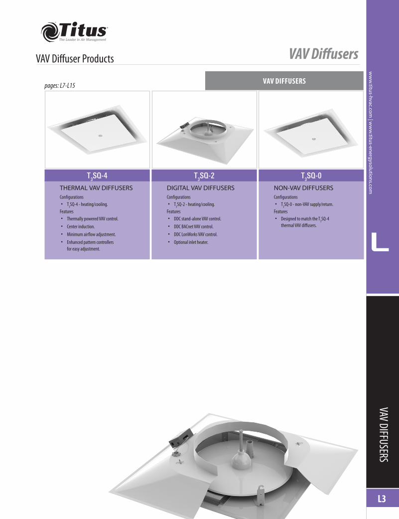
THERMAL VAV DIFFUSERSConfigurations• T3SQ-4 - heating/cooling.
Features• Thermally powered VAV control.• Center induction.• Minimum airflow adjustment.• Enhanced pattern controllers
for easy adjustment.
DIGITAL VAV DIFFUSERSConfigurations• T3SQ-2 - heating/cooling.
Features• DDC stand-alone VAV control.• DDC BACnet VAV control.• DDC LonWorks VAV control.• Optional inlet heater.
NON-VAV DIFFUSERSConfigurations• T3SQ-0 - non-VAV supply/return.
Features• Designed to match the T3SQ-4
thermal VAV diffusers.
pages: L7-L15

VAV Diffusers
L4
L
ww
w.ti
tus-
hvac
.co
m |
ww
w.ti
tus-
ener
gys
olu
tio
ns.
com
PERSONALIZED VAV SYSTEMSTitus brings both accuracy and flexibility to the variable air volume (VAV) market with T3SQ VAV diffusers. The T3SQ combines the functions of a VAV terminal and a high performance diffuser in one. The T3SQ modulates the air volume delivered to a zone to accurately control cooling and heating conditions. The unique variable geometry design results in maximum air distribution effectiveness at any air flow, for superior comfort conditions.
T3SQ adds application flexibility by being able to operate stand-alone with thermal or analog controls.
In addition to a superior performance VAV unit, the T3SQ is solidly constructed with 18-gauge steel. Available in many frame styles, the T3SQ can be installed in almost any ceiling as easily as a standard diffuser. The architecturally pleasing design coordinates with any office environment.
For applications that require system simplicity, proven technology and superior comfort, specify the Titus T3SQ series of VAV diffusers.
• Variable geometry diffuser design maintains jet velocity at all flow rates, varying air flow pattern for optimal performance.
• Separate cooling and heating setpoints on thermal T3SQ.
• Supply air temperature provides automatic cooling/heating changeover on configurations -4 and -2.
• T3SQ-2, digital, can control up to 14 drones.
• Optional electric inlet heater for applications requiring supplemental heat (T3SQ-2 only).
• Provides accurate, personal environmental temperature control to improve productivity in the office environment.
• Superior air distribution performance provides greater entrainment, higher Air Diffusion Performance Index (ADPI) and better ventilation effectiveness for Indoor Air Quality (IAQ).
• Lower cost per zone of control than typical VAV terminal with separate diffusers.
• Renovate existing offices or add zones in problem areas to solve individual comfort problems.
• Constant volume systems can easily become multi-zoned VAV systems, for “big building comfort” on a small building budget.
• Easy and inexpensive to relocate zones, ideal for use where office space may be reconfigured periodically.
• Easy to install and operate. • Unique center induction on thermal T3SQ-4 ensures accurate readings even at low flows.
Overview
Thermal VAV Diffuser
DESIGN FEATURES
DESIG
N FE
ATUR
ES
Single piece backpan with multiple border types available to complement various ceiling designs.
Easy to turn minimum airflow adjustment ring.
Supply air temperature sensor provides autochangeover from heating to cooling operation. Easy to turn heating and cooling setpoint
adjustment rings (heating setpoint adjusteronly available on heating / cooling units).
Venturi tube and center induction design provide fast and accurate response to changes in zone temperature.
A tight horizontal air pattern is achieved by the intelligent curvature design of the backpan.
Face plaque’s curved edge reduces diffuser sound and creates a smooth appearance.
Thermal actuator assembly lifts and lowers the control disc producing uniform air pattern in all positions.
Installation and relocation are made easy.

VAV Diffusers
L
L5
ww
w.titu
s-hvac.com
| ww
w.titu
s-energ
ysolu
tion
s.com
APPLICATION GUIDE
Thermal VAV Diffuser
CONSTANT VOLUME SYSTEM APPLICATION OPTIONThe Titus T3SQ system is ideal for use with a constant volume system. The T3SQ gives all the advantages of a VAV system at low pressure conditions and reduced installation cost. The T3SQ is a low pressure, pressure dependent, variable air volume (VAV) system. The T3SQ is designed to operate around 0.15”- 0.20” inlet pressure. This system provides zoned comfort, which is not always possible with a typical constant volume system.
1. It is recommended that a static pressure controller such as the Titus ZECV/ZQCV be installed into a constant volume system when more than 30 percent of the system airflow is put under the control of T3SQ
diffusers. This minimizes the possibility of delivering excess air when a portion of the Zcoms are operating at part load conditions.
2. When an entire constant volume system uses T3SQ zone control, a ZECV/ZQCV box should be implemented. The Titus ZECV/ZQCV pressure control terminal should be sized for 80 percent of the total supply flow, less the airflow of the smallest zone.
3. Care must be taken when sizing and installing a ZECV/ZQCV. The unit should be installed as far downstream from the fan as is practical to maximize supply and return air mixing. This reduces the risk of the unit cycling on high or low.
VARIABLE AIR VOLUME SYSTEM APPLICATION OPTIONThe Titus T3SQ system is ideal for use in buildings where the advantages of zoned variable air volume (VAV) systems normally cannot be used due to budget issues or plenum space constraints.
Special care should taken when determining the static pressure of a VAV system with T3SQ units.
For more information on ZECV and ZQCV, please refer to the Miscellaneous Terminals section of the catalog.
Application Guidelines
T3SQDiffuser
24 VAC
ZECV/ZQCVCVSystem
Return
StaticPressureTap
T3SQDiffuser
24 VACZECV/ZQCV
StaticPressureTap
Typical static pressure control by throttling supply air using a ZECV/ZQCV terminal.
Typical static pressure control by bypassing supply air using a ZECV/ZQCV terminal.
VAV Diffusers
L6
L
ww
w.ti
tus-
hvac
.co
m |
ww
w.ti
tus-
ener
gys
olu
tio
ns.
com
APPL
ICATIO
N GU
IDE
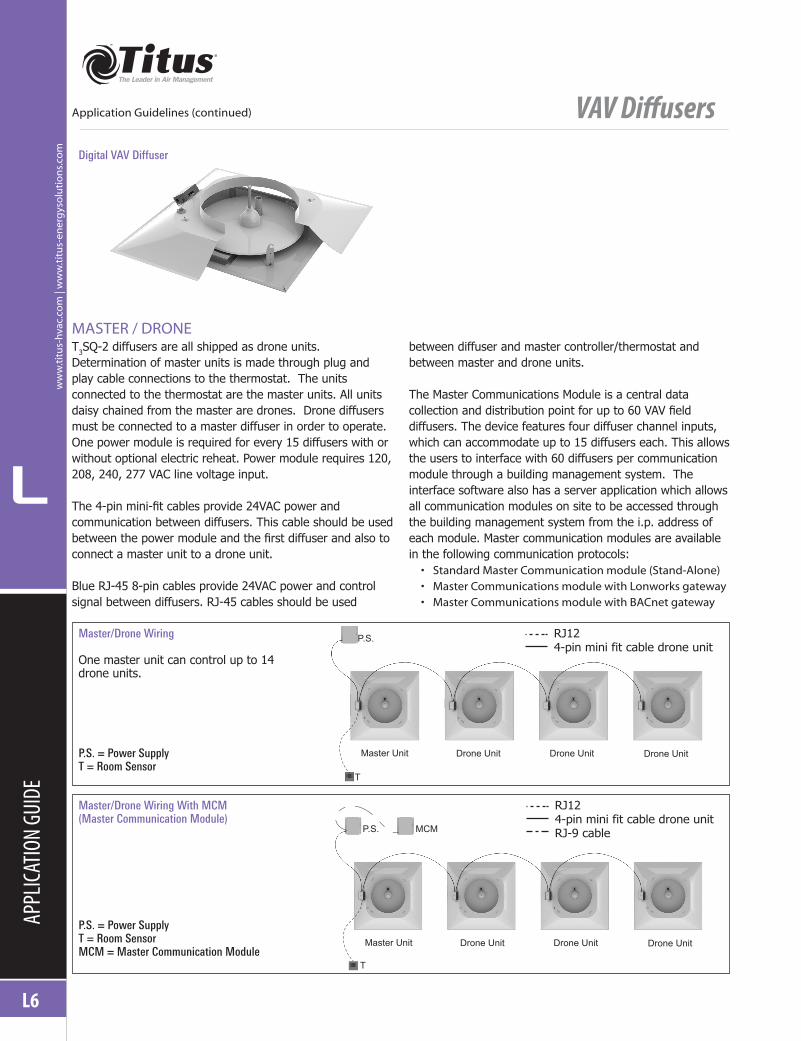
T3SQ-2 diffusers are all shipped as drone units. Determination of master units is made through plug and play cable connections to the thermostat. The units connected to the thermostat are the master units. All units daisy chained from the master are drones. Drone diffusers must be connected to a master diffuser in order to operate. One power module is required for every 15 diffusers with or without optional electric reheat. Power module requires 120, 208, 240, 277 VAC line voltage input.
The 4-pin mini-fit cables provide 24VAC power and communication between diffusers. This cable should be used between the power module and the first diffuser and also to connect a master unit to a drone unit.
Blue RJ-45 8-pin cables provide 24VAC power and control signal between diffusers. RJ-45 cables should be used
between diffuser and master controller/thermostat and between master and drone units.
The Master Communications Module is a central data collection and distribution point for up to 60 VAV field diffusers. The device features four diffuser channel inputs, which can accommodate up to 15 diffusers each. This allows the users to interface with 60 diffusers per communication module through a building management system. The interface software also has a server application which allows all communication modules on site to be accessed through the building management system from the i.p. address of each module. Master communication modules are available in the following communication protocols:• Standard Master Communication module (Stand-Alone)• Master Communications module with Lonworks gateway• Master Communications module with BACnet gateway
Application Guidelines (continued)
MASTER / DRONE
Master/Drone Wiring
One master unit can control up to 14 drone units.
P.S. = Power SupplyT = Room Sensor
Digital VAV Diffuser
Master/Drone Wiring With MCM (Master Communication Module)
P.S. = Power SupplyT = Room SensorMCM = Master Communication Module
RJ124-pin mini fit cable drone unitRJ-9 cable
RJ124-pin mini fit cable drone unit
P.S.
MCM
T
T
P.S.
Master Unit
Master Unit
Drone Unit
Drone Unit
Drone Unit
Drone Unit
Drone Unit
Drone Unit
VAV Diffusers
L
L7
ww
w.titu
s-hvac.com
| ww
w.titu
s-energ
ysolu
tion
s.com
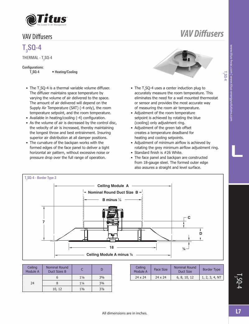
THERMAL - T3SQ-4
Configurations: T3SQ-4 •Heating/Cooling
• The T3SQ-4 is a thermal variable volume diffuser. The diffuser maintains space temperature by varying the volume of air delivered to the space. The amount of air delivered will depend on the Supply Air Temperature (SAT) (-4 only), the room temperature setpoint, and the room temperature.
• Available in heating/cooling (-4) configuration. • As the volume of air is decreased by the control disc, the velocity of air is increased, thereby maintaining the longest throw and best entrainment. Insuring superior air distribution at all damper positions.
• The curvature of the backpan works with the formed edges of the face panel to deliver a tight horizontal air pattern, without excessive noise or pressure drop over the full range of operation.
• The T3SQ-4 uses a center induction plug to accurately measure the room temperature. This eliminates the need for a wall mounted thermostat or sensor and provides the most accurate way of measuring the room air temperature.
• Adjustment of the room temperature setpoint is achieved by rotating the blue (cooling) only adjustment ring.
• Adjustment of the green tab offset creates a temperature deadband for heating and cooling setpoints.
• Adjustment of minimum airflow is achieved by rotating the grey minimum airflow adjustment ring.
• Standard finish is #26 White. • The face panel and backpan are constructed from 18-gauge steel. The formed outer edge also assures a straight and level surface.
All dimensions are in inches.
VAV DiffusersT3SQ-4
T3 SQ-4
Ceiling Module A
Face SizeNominal Round
Duct SizeBorder Type
24 x 24 24 x 24 6, 8, 10, 12 1, 2, 3, 4, NT
Ceiling Module A
Nominal Round Duct Sizes B
C D
24
6 1⅛ 3⅝
8 1¼ 3¾
10, 12 1⅜ 3⅞
T3SQ-4 - Border Type 3
Ceiling Module A
Nominal Round Duct Size B
B minus ⅛
C
D
¼Ceiling Module A minus ¼
18
7
T3 SQ-4
VAV Diffusers
L8
L
ww
w.ti
tus-
hvac
.co
m |
ww
w.ti
tus-
ener
gys
olu
tio
ns.
com
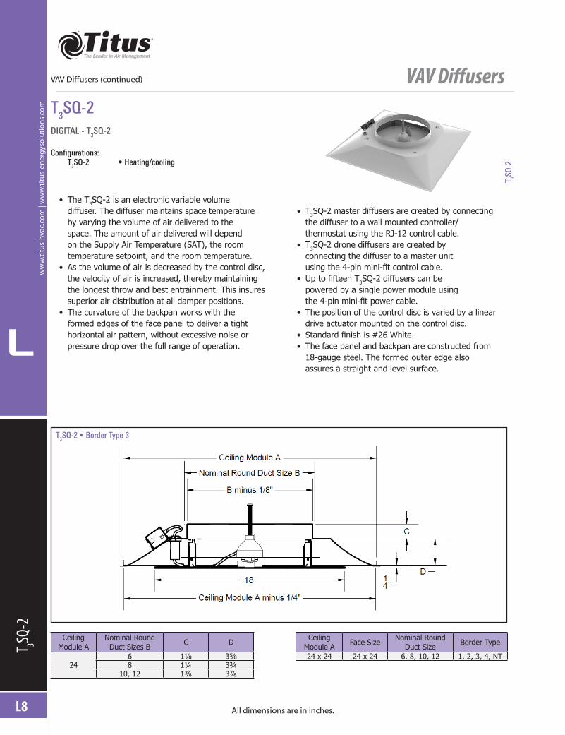
DIGITAL - T3SQ-2
Configurations: T3SQ-2 •Heating/cooling
• The T3SQ-2 is an electronic variable volume diffuser. The diffuser maintains space temperature by varying the volume of air delivered to the space. The amount of air delivered will depend on the Supply Air Temperature (SAT), the room temperature setpoint, and the room temperature.
• As the volume of air is decreased by the control disc, the velocity of air is increased, thereby maintaining the longest throw and best entrainment. This insures superior air distribution at all damper positions.
• The curvature of the backpan works with the formed edges of the face panel to deliver a tight horizontal air pattern, without excessive noise or pressure drop over the full range of operation.
• T3SQ-2 master diffusers are created by connecting the diffuser to a wall mounted controller/ thermostat using the RJ-12 control cable.
• T3SQ-2 drone diffusers are created by connecting the diffuser to a master unit using the 4-pin mini-fit control cable.
• Up to fifteen T3SQ-2 diffusers can be powered by a single power module using the 4-pin mini-fit power cable.
• The position of the control disc is varied by a linear drive actuator mounted on the control disc.
• Standard finish is #26 White. • The face panel and backpan are constructed from 18-gauge steel. The formed outer edge also assures a straight and level surface.
All dimensions are in inches.
VAV Diffusers (continued)
T 3SQ-2
T3SQ-2
Ceiling Module A
Nominal Round Duct Sizes B
C D
246 1⅛ 3⅝8 1¼ 3¾
10, 12 1⅜ 3⅞
Ceiling Module A
Face SizeNominal Round
Duct SizeBorder Type
24 x 24 24 x 24 6, 8, 10, 12 1, 2, 3, 4, NT
T3SQ-2•BorderType3
T 3SQ-2
VAV Diffusers
L
L9
ww
w.titu
s-hvac.com
| ww
w.titu
s-energ
ysolu
tion
s.com
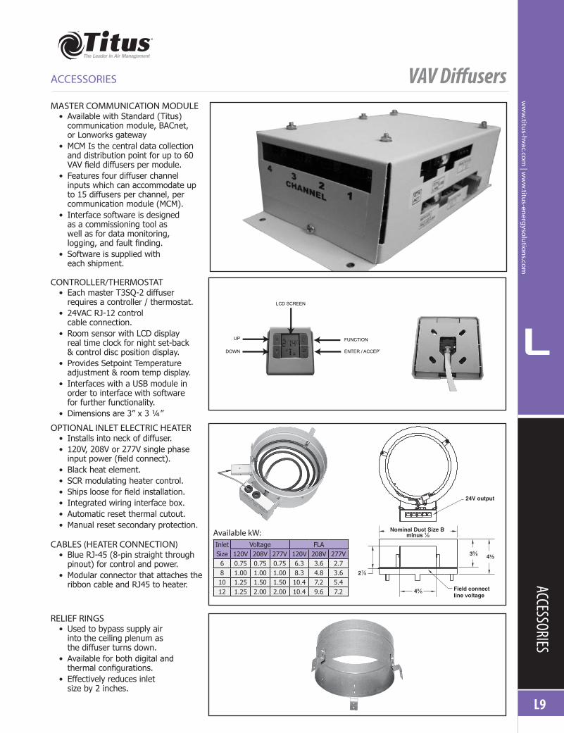
OPTIONAL INLET ELECTRIC HEATER • Installs into neck of diffuser. • 120V, 208V or 277V single phase input power (field connect).
• Black heat element. • SCR modulating heater control. • Ships loose for field installation. • Integrated wiring interface box. • Automatic reset thermal cutout. • Manual reset secondary protection.
CABLES (HEATER CONNECTION) • Blue RJ-45 (8-pin straight through pinout) for control and power.
• Modular connector that attaches the ribbon cable and RJ45 to heater. ACCESSORIES
ACCESSORIES
RELIEF RINGS • Used to bypass supply air into the ceiling plenum as the diffuser turns down.
• Available for both digital and thermal configurations.
• Effectively reduces inlet size by 2 inches.
MASTER COMMUNICATION MODULE • Available with Standard (Titus) communication module, BACnet, or Lonworks gateway
• MCM Is the central data collection and distribution point for up to 60 VAV field diffusers per module.
• Features four diffuser channel inputs which can accommodate up to 15 diffusers per channel, per communication module (MCM).
• Interface software is designed as a commissioning tool as well as for data monitoring, logging, and fault finding.
• Software is supplied with each shipment.
CONTROLLER/THERMOSTAT • Each master T3SQ-2 diffuser requires a controller / thermostat.
• 24VAC RJ-12 control cable connection.
• Room sensor with LCD display real time clock for night set-back & control disc position display.
• Provides Setpoint Temperature adjustment & room temp display.
• Interfaces with a USB module in order to interface with software for further functionality.
• Dimensions are 3” x 3 ¼”
24V output
Field connect line voltage
3⅝
4⅝
2⅞
Nominal Duct Size B minus ⅛
4½
Available kW:Inlet Size
Voltage FLA120V 208V 277V 120V 208V 277V
6 0.75 0.75 0.75 6.3 3.6 2.78 1.00 1.00 1.00 8.3 4.8 3.610 1.25 1.50 1.50 10.4 7.2 5.412 1.25 2.00 2.00 10.4 9.6 7.2
LCD SCREEN
UP
DOWN
FUNCTION
ENTER / ACCEPT
VAV Diffusers
L10
L
ww
w.ti
tus-
hvac
.co
m |
ww
w.ti
tus-
ener
gys
olu
tio
ns.
com
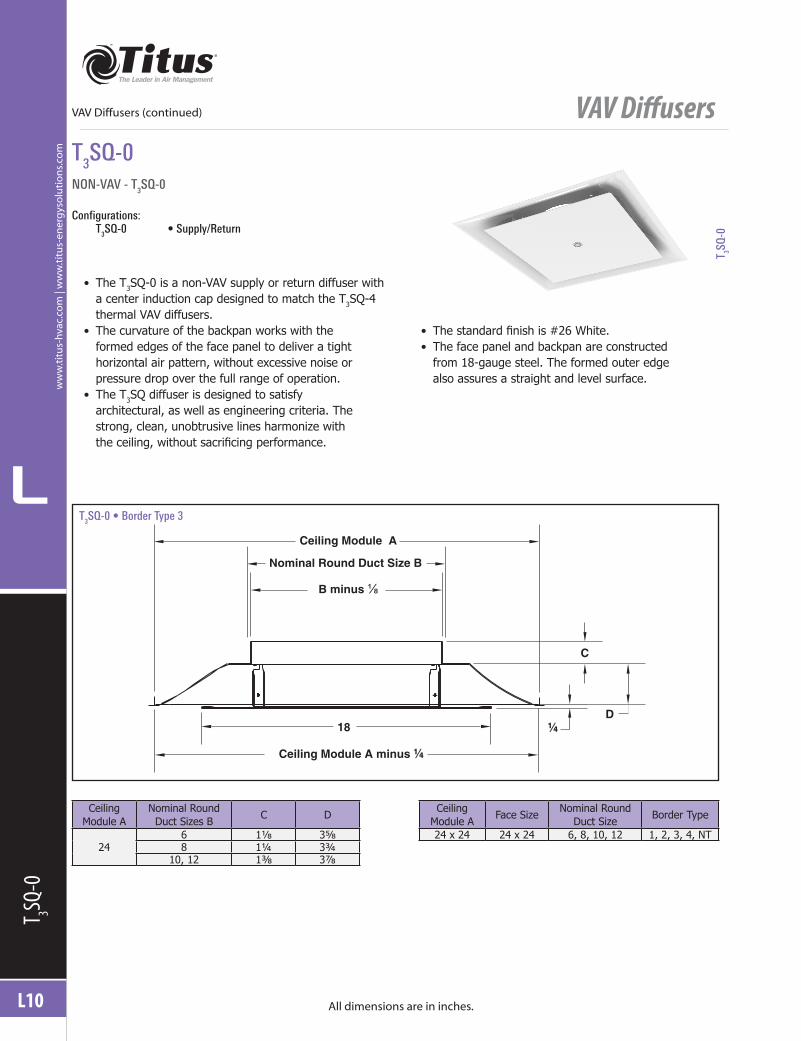
NON-VAV - T3SQ-0
Configurations: T3SQ-0 •Supply/Return
• The T3SQ-0 is a non-VAV supply or return diffuser with a center induction cap designed to match the T3SQ-4 thermal VAV diffusers.
• The curvature of the backpan works with the formed edges of the face panel to deliver a tight horizontal air pattern, without excessive noise or pressure drop over the full range of operation.
• The T3SQ diffuser is designed to satisfy architectural, as well as engineering criteria. The strong, clean, unobtrusive lines harmonize with the ceiling, without sacrificing performance.
• The standard finish is #26 White. • The face panel and backpan are constructed from 18-gauge steel. The formed outer edge also assures a straight and level surface.
All dimensions are in inches.
T3SQ-0
T 3SQ-0
Ceiling Module A
Nominal Round Duct Sizes B
C D
246 1⅛ 3⅝8 1¼ 3¾
10, 12 1⅜ 3⅞
Ceiling Module A
Face SizeNominal Round
Duct SizeBorder Type
24 x 24 24 x 24 6, 8, 10, 12 1, 2, 3, 4, NT
T 3SQ-0
T3SQ-0•BorderType3
Ceiling Module A minus ¼
18
B minus ⅛
Nominal Round Duct Size B
Ceiling Module A
D
C
¼
VAV Diffusers (continued)
VAV Diffusers
L
L11
ww
w.titu
s-hvac.com
| ww
w.titu
s-energ
ysolu
tion
s.com
BORDER TYPES
All dimensions are in inches.
BORDERS
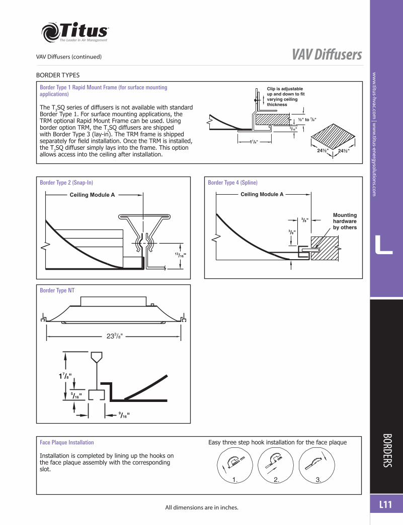
Border Type 1 Rapid Mount Frame (for surface mounting applications)
The T3SQ series of diffusers is not available with standard Border Type 1. For surface mounting applications, the TRM optional Rapid Mount Frame can be used. Using border option TRM, the T3SQ diffusers are shipped with Border Type 3 (lay-in). The TRM frame is shipped separately for field installation. Once the TRM is installed, the T3SQ diffuser simply lays into the frame. This option allows access into the ceiling after installation.
Clip is adjustableup and down to fitvarying ceilingthickness
½" to 7/8"
3/16"
11/8"
24½" 24½"
Border Type 2 (Snap-In) Border Type 4 (Spline)
13/16"
Ceiling Module A Ceiling Module A
3/8"
3/8"
Mountinghardwareby others
Border Type NT
233/8"
17/8"
9/16"
5/16"
Face Plaque Installation Easy three step hook installation for the face plaque
Installation is completed by lining up the hooks on the face plaque assembly with the corresponding slot.
1. 2. 3.
VAV Diffusers (continued)
VAV Diffusers
L12
L
ww
w.ti
tus-
hvac
.co
m |
ww
w.ti
tus-
ener
gys
olu
tio
ns.
com
PERF
ORMA
NCE D
ATA
PERFORMANCE DATA
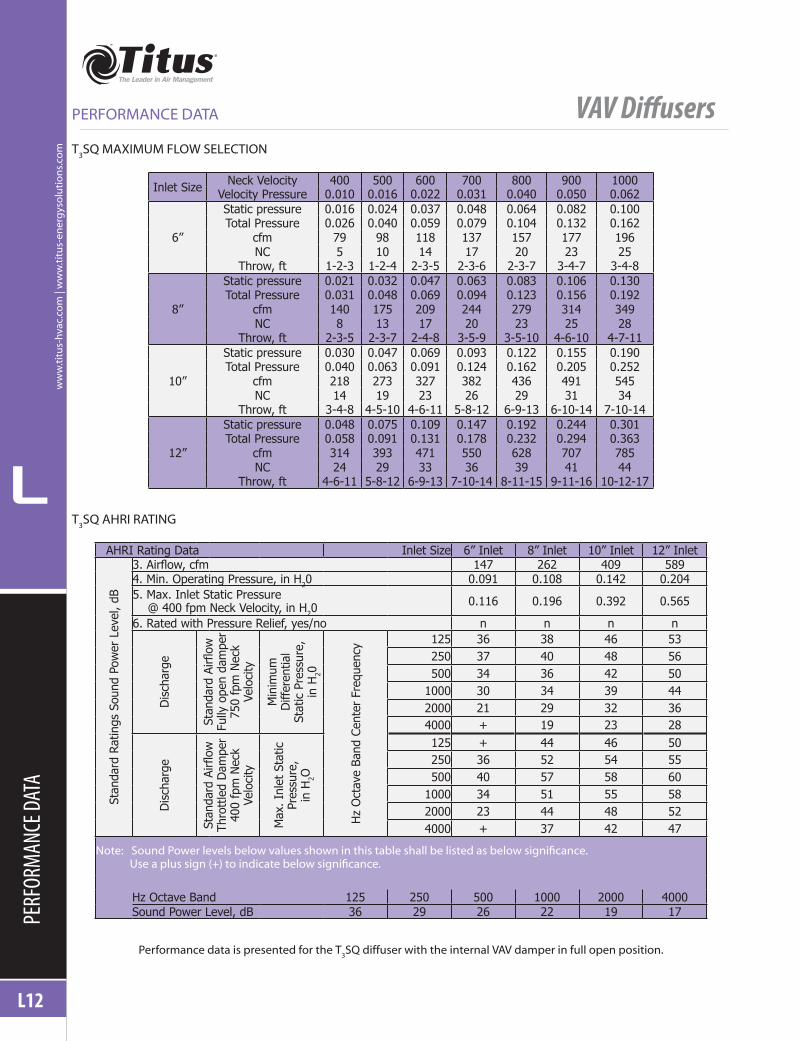
T3SQ MAXIMUM FLOW SELECTION
Inlet Size Neck Velocity 400 500 600 700 800 900 1000Velocity Pressure 0.010 0.016 0.022 0.031 0.040 0.050 0.062
6”
Static pressure 0.016 0.024 0.037 0.048 0.064 0.082 0.100Total Pressure 0.026 0.040 0.059 0.079 0.104 0.132 0.162
cfm 79 98 118 137 157 177 196NC 5 10 14 17 20 23 25
Throw, ft 1-2-3 1-2-4 2-3-5 2-3-6 2-3-7 3-4-7 3-4-8
8”
Static pressure 0.021 0.032 0.047 0.063 0.083 0.106 0.130Total Pressure 0.031 0.048 0.069 0.094 0.123 0.156 0.192
cfm 140 175 209 244 279 314 349NC 8 13 17 20 23 25 28
Throw, ft 2-3-5 2-3-7 2-4-8 3-5-9 3-5-10 4-6-10 4-7-11
10”
Static pressure 0.030 0.047 0.069 0.093 0.122 0.155 0.190Total Pressure 0.040 0.063 0.091 0.124 0.162 0.205 0.252
cfm 218 273 327 382 436 491 545NC 14 19 23 26 29 31 34
Throw, ft 3-4-8 4-5-10 4-6-11 5-8-12 6-9-13 6-10-14 7-10-14
12”
Static pressure 0.048 0.075 0.109 0.147 0.192 0.244 0.301Total Pressure 0.058 0.091 0.131 0.178 0.232 0.294 0.363
cfm 314 393 471 550 628 707 785NC 24 29 33 36 39 41 44
Throw, ft 4-6-11 5-8-12 6-9-13 7-10-14 8-11-15 9-11-16 10-12-17
T3SQ AHRI RATING
AHRI Rating Data Inlet Size 6” Inlet 8” Inlet 10” Inlet 12” Inlet
Stan
dard
Rat
ings
Sou
nd P
ower
Lev
el, d
B
3. Airflow, cfm 147 262 409 5894. Min. Operating Pressure, in H20 0.091 0.108 0.142 0.2045. Max. Inlet Static Pressure @ 400 fpm Neck Velocity, in H20
0.116 0.196 0.392 0.565
6. Rated with Pressure Relief, yes/no n n n n
Dis
char
ge
Stan
dard
Airfl
ow
Fully
ope
n da
mpe
r 75
0 fp
m N
eck
Velo
city
Min
imum
D
iffer
entia
l St
atic
Pre
ssur
e,
in H
20
Hz
Oct
ave
Band
Cen
ter
Freq
uenc
y 125 36 38 46 53250 37 40 48 56500 34 36 42 50
1000 30 34 39 442000 21 29 32 364000 + 19 23 28
Dis
char
ge
Stan
dard
Airfl
ow
Thro
ttle
d D
ampe
r 40
0 fp
m N
eck
Velo
city
Max
. Inl
et S
tatic
Pr
essu
re,
in H
2O
125 + 44 46 50250 36 52 54 55500 40 57 58 60
1000 34 51 55 582000 23 44 48 524000 + 37 42 47
Note:SoundPowerlevelsbelowvaluesshowninthistableshallbelistedasbelowsignificance.Useaplussign(+)toindicatebelowsignificance.
Hz Octave Band 125 250 500 1000 2000 4000Sound Power Level, dB 36 29 26 22 19 17
Performance data is presented for the T3SQ diffuser with the internal VAV damper in full open position.

VAV Diffusers
L
L13
ww
w.titu
s-hvac.com
| ww
w.titu
s-energ
ysolu
tion
s.com
PERFORMANCE DATA
AIR DISTRIBUTION AT VARIOUS DAMPER POSITIONS
The performance of the T3SQ diffuser is related to supply static pressure and size. If the supply static pressure is held at a constant value and the VAV diffuser damper is throttled to a closed position, the airflow pattern is changed from a square pattern to a star pattern. The isovel in the adjacent illustration demonstrates this pattern change. With the
reduction of cfm, throw does not decrease as in standard diffusers. As the damper closes the discharge velocity is slightly increased, minimizing throw reduction. With a fixed inlet pressure, the sound values have very small changes of intensity as the damper is modulated.
PERFORMANCE DATA
Airflow Pattern Changes
Note: The isovel changes as the diffuser damper modulates from open to close (oranycombinationbetween)causingvariationstotheariflowpattern.
MinimumPosition
50% Open
Sensor
Fully Open

VAV Diffusers
L14
L
ww
w.ti
tus-
hvac
.co
m |
ww
w.ti
tus-
ener
gys
olu
tio
ns.
com
SPEC
IFICA
TIONS
SUGGESTED SPECIFICATIONS
Available Models: T3SQ-4 •Thermal T3SQ-2 •Digital
T3SQ-4 HEATING / COOLING THERMALLY POWERED VAV
DIFFUSER
Furnish and install Titus model T3SQ thermally powered VAV diffusers with heating / cooling changeover.
Each diffuser shall be thermally powered to infinitely vary the supply of air into the space, in either heating or cooling mode, by means of regulating a variable aperture damper, known as a control disc, vertically within the diffuser. Supply air from the variable geometry diffusers will discharge horizontally in a 360° pattern and will maintain constant air movement in the space throughout the range of volume variation from 100% down to 25%.
The thermal room sensing element shall be located behind an induction cap in the center of the diffuser panel and shall provide no more than 1°F thermal deadband between induced temperature and zone temperature.
Each diffuser shall be individually adjustable to sense room temperature within the space between 68°F and 77°F. Each diffuser shall be individually adjustable for minimum airflow from 0 to 30%. Each diffuser is to be fitted with a single thermal supply air sensing element to automatically change from and to a cooling and heating mode and be able to infinitely vary the supply of air into the space in either mode. Each diffuser shall be self-contained and require no external power source to maintain space temperature throughout the range of operation. The T3SQ-4 thermal diffusers shall carry the manufacturer’s 10-year warranty.
Ceiling diffusers shall be square, architectural, panel face diffusers. The diffuser shall have an 18-gauge steel face panel mounted on an aerodynamically shaped, one piece, seamless back pan. The diffuser face panel must be field removable by means of four positive locking clips. The exposed surface of the face panel shall be smooth, flat and free of visible fasteners. The face panel cannot project more than ⅛-inch below the outside border of the diffuser back pan.
The face panel shall have an aerodynamically shaped, hemmed edge. A single metal thickness on the edges of the face panel is not acceptable. Ceiling diffusers with a 24 x 24-inch full face shall have no less than an 18 x 18-inch face panel. The entire diffuser shall be constructed of steel, with an integral drawn inlet. The diffuser neck shall have a minimum 1⅛-inch depth available for duct connection.
Finish shall be a thermoset alky-melamine enamel paint, baked at 315°F. The paint hardness must be 2H to 3H. The paint must pass a 300-hour ASTM D1654 Corrosive Environments Salt Spray Test without creepage, blistering or deterioration of film. The paint must pass the 500-hour ASTM D870 Water Immersion Test. The paint must also pass the ASTM D2794 Reverse Impact Cracking Test with 50-inch pound applied.
Alternatives to the specified product must provide published performance ratings that meet or exceed the performance of the T3SQ ceiling diffuser. All test data shall be obtained in accordance with ANSI/ASHRAE Standard 70–2006 and AHRI Standard 880. A copy of the certified test results shall be provided upon request. The VAV diffuser shall be AHRI certified.
T3SQ-2 DIGITAL ELECTRONIC VAV DIFFUSER WITH
HEATING/COOLING CHANGEOVER
Furnish and install Titus model T3SQ digital electronic VAV diffusers. Each diffuser shall be electronically controlled by a 24VAC actuator to infinitely vary the supply of cold air into the space by means of regulating a variable aperture damper, known as a control disc, vertically within the diffuser. Supply air from the variable geometry diffusers will discharge horizontally in a 360° pattern and will maintain constant air movement in the space throughout the range of volume variation from 100% down to 25%.
The room sensing element shall be located in the master controller/thermostat unit. Each diffuser shall be adjustable to sense room temperature within the space between 65°F and 80°F. In large zones, up to 14 drone units connected to a master unit can be used. Each diffuser shall have an electronic wiring interface having RJ-12 sockets for easy interfacing with master controller/thermostat and 4-pin connection for adjacent parallel master and drone diffusers. Each diffuser shall have a changeover sensor to determine supply air temperature and change the diffuser from heating to cooling operation.
The Master Communications Module is a central data collection and distribution point for up to 60 VAV diffusers. The device features four diffuser channel inputs, which can accommodate up to 15 diffusers each. Communication on these channels is by means of a Lin bus interface to four field Power Supply units connected by dedicated communication cables.
This centralized data is monitored on a PC running the MLM software Application via an Ethernet TCP/IP interface. The MLM software Application is designed as a commissioning

VAV Diffusers
L
L15
ww
w.titu
s-hvac.com
| ww
w.titu
s-energ
ysolu
tion
s.com
SPECIFICATIONS
SUGGESTED SPECIFICATIONS
tool as well as for data monitoring, logging and fault finding which is supplied by Titus.
In addition to the collection and distribution between field diffusers and the MLM Application, the unit also features an on-board web server. This web server can be accessed by a standard browser tool and is used to setup IP addresses, Device identification data as well as communications parameters. In general the web server is used on initial installation to bind to the IP network and to uniquely identify the product, normally by physical location.
A serial USB port provides limited diagnostic capability. In general it is used in production to set MAC, IP and port addresses. It can be used to verify and set port and IP addresses.
A LON compatible gateway is achieved by adding a plug-in hardware module to the MCU. This hardware module contains a subset of the ANSI/CEA-709.1-B (EN14908.1) protocol stack and interface via a TP/FT-10 (Free topology) transceiver network to the device bus. The functional block implementation is indicated in LHA DOC BQ0254-A. Up to 20 of these functional blocks can be selected for a client interface to 20 master control zones. Again the user has the option to use the MLM Application for diffuser setup and diagnostics and the Lon client for general control supervision.
One ETL rated power module, model T3PM shall be required for every 15 T3SQ-2 diffusers with or without optional electric heaters. The power module shall have a optional 120V, 208V, 240V, 277V/24VAC transformer and a power filter to provide clean 24VAC to the diffusers. All connections, except line voltage to the power module or optional inlet electric heater, shall be made using plug-n-play 4-pin minifit connector cables.
Optional ETL listed inlet incoloy “black heat” sheathed electric heater shall install into the inlet of the diffuser and be protected by two automatic thermal cutouts and
an airflow proving switch. Inlet electric heaters shall be controlled proportionally by means of triac heater controllers (SCR), each having an electronic wiring interface having three RJ-45 and 2 RJ-12 sockets for easy interfacing with master controller/thermostat and/or adjacent parallel master and drone diffusers. The inlet electric heater shall have a 2°F proportional band and be energized at 1°F below room temperature set point. Ceiling diffusers shall be square, architectural, panel face diffusers. The diffuser shall have an 18-gauge steel face panel mounted on an aerodynamically shaped, one piece, seamless backpan. The diffuser face panel must be field removable by means of four positive locking clips. The exposed surface of the face panel shall be smooth, flat and free of visible fasteners. The face panel cannot project more than ⅛-inch below the outside border of the diffuser backpan.
The face panel shall have an aerodynamically shaped, hemmed edge. A single metal thickness on the edges of the face panel is not acceptable. Ceiling diffusers with a 24 x 24-inch full face shall have no less than an 18 x 18-inch face panel. The entire diffuser shall be constructed of steel, with an integral drawn inlet. The diffuser neck shall have a minimum 1⅛-inch depth available for duct connection.
Finish shall be a thermoset alky-melamine enamel paint, baked at 315°F. The paint hardness must be 2H to 3H. The paint must pass a 300-hour ASTM D1654 Corrosive Environments Salt Spray Test without creepage, blistering, or deterioration of film. The paint must pass the 500-hour ASTM D870 Water Immersion Test. The paint must also pass the ASTM D2794 Reverse Impact Cracking Test with 50-inch pound applied.
Alternatives to the specified product must provide published performance ratings that meet or exceed the performance of the T3SQ ceiling diffuser. All test data shall be obtained in accordance with ANSI/ASHRAE Standard 70–2006 and AHRI Standard 880. A copy of the certified test results shall be provided upon request. The VAV diffuser shall be AHRI certified.

VAV Diffusers
L16
L
ww
w.ti
tus-
hvac
.co
m |
ww
w.ti
tus-
ener
gys
olu
tio
ns.
com
SPEC
IFICA
TIONS
SUGGESTED SPECIFICATIONS VAV DiffusersMODEL NUMBER SPECIFICATION
Border TypeNeck Size 2
6 38 4
Model 10 512 NT
T3SQ X X X X
0 Non-VAV supply/return 26 White2 Digital Finish4 Thermal (heating & cooling)
Configuration