l u b r i c an t s an d h yd r au l i c f l u i d s : t y pe s
TRANSCRIPT

Lubricants and Hydraulic Fluids: Types Course No: T10-001
Credit: 10 PDH
Gilbert Gedeon, P.E.
Continuing Education and Development, Inc.
22 Stonewall Court
Woodcliff Lake, NJ 07677
P: (877) 322-5800

EM 1110-2-1424 29 Jan 16
9-1
CHAPTER 9
Turbine Oils
9-1. Description. The term “turbine oils” broadly refers to oils used for hydro turbines, steam turbines, and gas turbines. It is common to use the same general category of oil for all of these types of turbines. The demands on steam and gas turbines are higher as bearing temperatures are much higher for these machines. It is unusual to run bearing temperatures on hydro turbines beyond 167 °F (75 °C), while gas and steam turbines can run in the 248 °F (120 °C) range. Because of these temperature differences and the higher oxidation that can result, new generations of more oxidation resistant oils are being developed for gas and steam turbines. Many of the old turbine oil brands and types are no longer used for gas and steam turbines, though they still may be used in hydro turbines.
a. Hydro turbines, whether Francis, Pelton, or Kaplan designs, vertical or horizontal shaft, generally have a minimum of two journal bearings and one thrust bearing. These bearings consist of some form of babbitt surface bonded to a steel backing. The rotating element of the bearing is usually polished steel, either an integral part of the turbine shaft or else attached mechanically to the shaft. The thrust bearing is usually the most highly loaded bearing in the machine. The thrust bearing resists hydraulic thrust developed by the axial component of the force of the water on the turbine wheel. In the case of vertical shafts, the thrust bearing also supports the weight of the rotating parts of the hydro generator. In the case of horizontal shaft machines, the shaft bearings support the weight of the rotating parts. In the case of Pelton wheels, the shaft bearings also support the component of the hydraulic thrust that is perpendicular to the shaft. In the case of both horizontal and vertical shaft hydro generators, the shaft bearings support and stabilize the shaft and resist the forces of imbalance.
b. In general, the manufacturer of the hydro generator supplies a list of acceptable lubricating oils for a particular unit as part of the operation and maintenance data. Specifically, this recommendation should include a chart of viscosities acceptable for various operating conditions. The oil recommendation will also include whether antiwear (AW) additives are necessary. The manufacturer has selected oils that will assure long life and successful operation of the equipment. The type of oil selected is usually of the general type called turbine oil. Even though this designation refers more to steam and gas turbines than hydro turbines, many of the operating requirements are similar. This makes turbine oil the most common type of commercially available lubricating oil used in hydro turbines.
c. Most hydro turbines are connected to a plant oil system that has a centrally located oil filtration and moisture removal system. The governor system often uses oil from the same system so, in addition to lubricating the bearings, the oil must function satisfactorily in the governor. The following discussion identifies the requirements for selecting turbine lubricating oils. For additional information on lubrication and oil requirements for hydroelectric applications, refer to EM 1110-2-4205, Hydroelectric Power Plants, Mechanical Design (30 June 1995).
9-2. Functions. In a hydro turbine, the oil serves multiple functions. It is a hydrodynamic lubricant for turbine and generator guide bearings and thrust bearings. It is a boundary

EM 1110-2-1424 29 Jan 16
9-2
lubrication fluid in the turbine runner hub, and it is a hydraulic fluid by which the governor controls the turbine. It also serves as a heat transfer fluid.
a. Bearings. The oil acts as a hydrodynamic lubricant in the journal bearings of the turbine and generator (e.g., Figure 9-1). The turbine guide bearing is typically a fixed diameter babbitted bearing. Generator guide bearings are similar, but typically use multiple adjustable bearing shoes. Thrust bearings operate on the same principle, but the bearing shoes are flat instead of curved. They resist much higher loads. It is common for thrust bearing loads to be in the range of 2 to 4 million pounds and sometimes even higher. A thrust runner is attached to the shaft and forms the mating bearing surface. The shoes are babbitted and the runner is steel. The runner must be precisely flat and square to the shaft with extremely tight tolerances. The oil film thickness is in the range of 0.001 to 0.002 in., which explains why such extremely tight tolerances are needed. Being significantly out of tolerance would create instabilities in the fluid film leading to bearing failure.
Figure 9-1. Bonneville Dam – Hydroturbine Units.
(1) The fluid wedge formed resists the bearing forces. Changes to the thickness of the fluid wedge can occur due to shaft vibration, alignment, shaft dogleg, load changes, changes in viscosity, oil whirl, or oil whip. Ideally no contact of the shaft to bearing shell ever occurs. However on startup, some contact is likely. Thrust bearing operating temperatures vary with the design of the turbine and generator and cooling system, but are typically less than 167 °F (75 °C). In most cases, turbine and generator guide bearings run significantly cooler, but this is not always true if the bearing clearance are too tight or other conditions exist that create additional load.

EM 1110-2-1424 29 Jan 16
9-3
(2) Since bearings are the function that results in the highest oil temperature, it is important to remember that operating temperature greatly affects oil life. As a rule of thumb, for every 50 °F (10 °C) increase in oil temperature, the oxidation rate in the oil doubles.
b. Tilting Pad Bearings. This is an example of hydrodynamic lubrication. Tilting pad bearings are used for thrust bearings. A smooth thrust runner is attached to the shaft as one bearing surface. Below that are the tilting pads for the other bearing surface (Figure 9-2). As the machine rotates, a wedge of fluid is formed as in any hydrodynamic bearing. A mechanism is employed to allow the pads to tilt. Sometimes it is a pivot for the pad to freely rotate about and some bearings use a spring bed. Often to enhance performance and allow the oil wedge to more effectively develop, springs are removed and replaced with spacers near the leading edge. On most hydro turbine machines, an ISO VG (Viscosity Grade) 68 oil would be used. Lighter oils can be used, but are less forgiving such that many parameters must be considered carefully. Lack of adequate lubrication of tilting pad bearings can lead to failure (Figure 9-3). It is essential to build adequate oil film at startup and at speed. In most cases, a high lift pump should be used to develop the initial oil film. A good conservative value for starting film thickness is 0.003 to 0.005 in.
c. Generator Guide bearings. Generator and turbine guide bearings are another example of hydrodynamic lubrication. Generator guide bearings have shoes with adjustable clearance where turbine bearings have fixed clearance. Both operate by developing a wedge of fluid to support the radial load. Loads on these bearings are less than on thrust bearings. In real operation, the behavior of the oil film is dynamic. In a well performing bearing, the wedge never collapses and problems never occur. Because of issues such as bearing deformities, hydraulic and electrical instabilities, alignment, balance, and others, the oil film is often dynamic and can collapse. These are known as “rubs” (Figure 9-4). Shaft vibration monitoring is often added, and this can allow one to see and analyze the problems. Sometimes, more severe oil instability problems such as oil whip and oil whirl can occur.
Figure 9-2. Tilting Pad Thrust Bearing Assembly

EM 1110-2-1424 29 Jan 16
9-4
Figure 9-3. Damaged Tilting Pad Bearings.
Figure 9-4. Orbit Plot from X and Y Proximity Probes Monitoring Shaft Displacement on a Hydrodynamic Bearing. The Plot Shows Eight Revolutions of the Shaft. The Loop Indicates
That There Is a Bearing Rub during Each Revolution. During the Bearing Rub, Hydrodynamic Lubrication Is Lost.

EM 1110-2-1424 29 Jan 16
9-5
d. Governors. The turbine oil is used as a hydraulic fluid. The governor along with the turbine servomotors are the hydraulic system. A governor consists of a high pressure pump, an accumulator tank, an unpressurized reservoir, control valves, hydraulic lines, filters, and actuators called servomotors. Servomotors develop the force that is used by the wicket gates to regulate the flow of water through the turbine, and thus the amount of power generation it generates. Governors generally use the same oil as is used in the hydro generator guide and thrust bearing system. Governors that operate at over 1000 psi (68.9 bar) may require an antiwear additive to the oil, but these are not common. Turbine oils operate successfully in the governor system because the requirements for the oils are very similar. For example, antifoam characteristics prevent compressible foam from being introduced into the high pressure lines. Also, Rust and Oxidation (R&O) characteristics are needed because the high pressure pumps and the pilot valve assembly have very small clearances. Rust or other oxidation products could be transported into those clearances and cause the pump to wear or the pilot valve to stick or be sluggish, resulting in a degradation or loss of governor function. Auxiliary filters are sometimes used to keep the governor oil supply free of particulates. This becomes critical with digital governors using proportional or servo valves. Kidney loop filtration systems are also recommended as part of the overall filtration system. In many typical hydraulic systems, that is not the typically provided. But, it has been proven as a successful means to contamination control for hydro turbine governors.
(1) Oil is pumped from a sump using positive displacement pumps into an air-oil tank. The air-oil tank provides pressure to the four-way hydraulic valves used for control of wicket gates and blades (Kaplan units only, e.g., Figure 9-5). The four-way hydraulic valves are called distributing valves on hydro units. From the distributing valves, two lines are routed to the hydraulic cylinders, the same as in any typical hydraulic system. The distributing valves are moved by a pilot valve and piston. The pilot valve is mechanically operated by linkages on a mechanical governor. It is a proportional valve on a digital governor.
(2) The air-oil tank typically has no physical barrier between the air and oil. On smaller systems, nitrogen bladder or piston accumulators are sometimes used. Air ingresses into the oil at the air-oil interface of this pressurized tank, taking air from the tank. On systems with excessive foam, air can sometimes cross the air-oil interface in the other direction, adding air to the tank.
(3) Some of the major areas of concern are oxidation of the oil and the eventual formation of varnishes. Another area of concern is foaming, and that has effects on the accuracy and stability of the hydraulic system and increased oxidation as the air runs through pumps, resulting in microdieseling.
e. Wicket Gates. Wicket gates have two or three journal bearings and one thrust bearing or collar per gate. The journal bearings resist the hydrostatic and hydrodynamic loads involved in regulating the flow of water into the turbine. They also resist bending in the shaft that results from the thrust of the actuating linkage. The thrust bearing or collar positions the wicket gate vertically between the upper and lower surfaces of the speed ring in the distributor. The thrust collar has to support the weight of the wicket gates, but under some conditions must resist an upward thrust as well. Wicket gate bearings are subject to high loads, and the shafts do not make complete revolutions, but instead move over an arc, with usually about 90 degrees of motion from completely closed to completely open. This quarter-turn usually takes 5 seconds or more.

EM 1110-2-1424 29 Jan 16
9-6
An improperly adjusted governor may hunt, moving the gates back and forth continually in an arc as small as 1 degree. Even when shaft seals are provided, the grease can come into contact with water. In the worst cases, water can wash the lubricant out of the bearings.
(1) Traditionally, wicket gate bearings have been lubricated with a lithium-based, EP NLGI-2 grease. Auto-lubrication can be used to provide fresh grease every day. Generally, the bearings in the wicket gate linkages are lubricated with the same grease and by the same system. Environmental concerns have led to attempts to use environmentally acceptable greases. Refer to Chapter 13 for guidance on environmentally acceptable lubricants.
(2) A way to reduce or eliminate the release of greases to the environment is to use self-lubricating bearings or bushings. See Chapter 12 for further discussion and EM 1110-2-2610, Mechanical and Electrical Design of Navigation Locks and Dams (30 June 2013). There are many suppliers of such bushings. Refer to Construction Engineering Research Laboratory (CERL) Technical Report 99/104, Greaseless Bushings for Hydropower Applications: Program, Testing, and Results for guidance on such bearings (Jones et al. 1999).
Figure 9-5. Kaplan Turbine.

EM 1110-2-1424 29 Jan 16
9-7
Figure 9-6. Francis Turbine Runner Transported into Powerhouse.
Figure 9-7. Generator Rotor (460-ton).
9-3. Turbine Oil Basics. Turbine oil for hydro generating units has relatively mild service when compared to other turbine types and other industrial applications. However, hydro turbine oil is expected to have a longer service life than most applications. From past history, 30 yrs of service is considered quite normal. To achieve this, attention to oil properties, oil compatibility, and

EM 1110-2-1424 29 Jan 16
9-8
replacement procedures is absolutely necessary. Turbine oils for hydro units will be either ISO VG 68 or 100. ISO VG 68 is most common. ISO Grade 100 is used on many Kaplan units. In certain situations, it has better boundary lubrication characteristics for the turbine blades. Specific additives have also been recently used to help improve boundary lubrication.
a. In the past, Group I turbine oil was the norm. Though the oxidation rate was higher than current oils, the high solvency could readily dissolve any varnishes that formed. Group II oils are almost exclusively produced today by refineries. They have better oxidation properties as evidenced by higher RPVOT values or turbine oil stability test (TOST) values. Even though they have better oxidation resistance, their lack of solvency can frequently allow varnish to form deposits when oxidation progresses too far. RPVOT has been the most common property to specify for turbine oils. TOST is also a valid measure of oxidation resistance. It is common to specify TOST for oils used for gas and steam turbines, which, because of their severity of service, have some new oils with extremely high oxidation resistance.
b. There are a few limited sources for Group I oils, though they are rare at this time. There are some vendors that claim they are supplying Group I, but are inaccurate in that claim. One way to know for sure is to test the oil per ASTM D611, “Standard Test Methods for Aniline Point and Mixed Aniline Point of Petroleum Products and Hydrocarbon Solvents.” The aniline point for Group I napthenic oils in the range of 158 to 212 °F (70 to 100 °C). For Group I paraffinic oils, it is 194 to 230 °F (90 to 110 °C). For Group II oils, it is 212 to 266 °F (100 to 130 °C). *
c. The oil must be R&O inhibited and have an antifoam additive. Hydro turbines do have exposure to water, though often water is introduced from the atmosphere through tank breathers. Keeping water content low is important and the rust inhibitors provide additional protection for the system. Oxidation inhibitors are critical. Having a high initial RPVOT value is an indicator of the effectiveness of the oxidation inhibitors. Antifoam additives are critical to operation of the hydropower unit. High foam can cause operational problems and is likely to reduce life as the air passes through the pump and causes accelerated oxidation.
d. The oil should also be resistant to emulsification and separate readily from water. This allows water to be more readily separated from the oil by whatever means the system has available whether it is coalescing media, vacuum dehydration, or other.
e. Extreme pressure additives are typically not present in turbine oils. Antiwear additives are present in a few of the turbine oils. Extreme pressure and antiwear additives can have some effect on the results of lubricity tests. They are not as effective as boundary lubricity additives, which truly enhance performance in boundary lubrication. Stock turbine oils do not contain such lubricity additives.
9-4. Guidance on the Use of UFGS Turbine Oil Specification. For specifying new oil, use UFGS 48 13 19.00, Turbine Oil (May 2014). This is available under UFGS on the Whole Building
* Tribology and Lubrication Technology, New Base Oils Pose a Challenge for Solubility and Lubricity, Dr. Boris
Zhmud and Michel Roegiers, July 2009

EM 1110-2-1424 29 Jan 16
9-9
Design Guide web site. This specification should be used whenever purchasing new turbine oil. For delivery, storage, and handling of the oil, it is up to the user to develop specifications specific to their site. These should be included in separate specification sections.
a. When soliciting for new contracts or orders using this specification for purchase of turbine oil that will be mixed with the in-service oil or as a replacement oil, the Government should require all bidders to provide a 1- gallon (3.78-L) sample of the proposed oil, which must meet the oil properties of Section 48 13 19.00 to be eligible for award. The Government shall test this oil for compatibility with the in-service oil by sending a portion (typically 1 qt, but check with the lab for specific requirements) of new oil in an unmarked container, and a sample of in-service oil to a lab.
b. Before awarding the contract, the compatibility of new oil must be verified by the ASTM D7155 Test, “Standard Practice for Evaluating Compatibility of Mixtures of Turbine Lubricating Oils.” The tests are performed in various mixtures of 100% old oil, 90% old/10% new, 50% old/50% new, 10% old/90% new, and 100% new. The 100% old and 100% new tests are used to verify that there is no cloudiness in either of these oils that may invalidate the tests. 10% old and 90% new is representative of what can be expected after adding the new oil in the system. It is very expensive to ensure all of the old oil is removed. The other ratios are useful since various zones in the system may temporarily be exposed to different mix ratios.
9-5. Turbine Oil Selection. The importance of compatibility testing cannot be overstated. The reader should refer to Appendix G, ERDC/CERL TR-04-28, Performance Problems with Group 2 Hydrocracked Turbine Oils in Corps of Engineers Hydropower Facilities (Micetic and Beitelman 2004). This provides discussion on compatibility problems between Group 1 and Group 2 turbine oils. The purpose of compatibility is to ensure an absence of chemical reactions between the new and existing oil. The reactions that occur are between the additives, not the old Group I and new Group II base oils. The additive chemistries are in general proprietary so it is unpredictable what may happen when mixing the two oils. The compatibility tests answer this question reliably. Another factor is that the old oil often contains a mixture of oils that may have occurred over a period of many years. Even if the same oil was used for years, the additive package was not necessarily consistent. Depending on the severity and duration of use for incompatible oils, it will very likely be necessary to flush piping, physically wipe out sumps or replace some components to restore the system to an acceptable condition. Incompatible oils are a leading cause of accelerated varnish formation. Of particular concern is any reaction that may deplete antioxidant additives. This can greatly shorten the usable life of the oil and accelerate the time where varnish and deposits may occur. Cleaning and flushing should also be done when replacing turbine oil. Refer to ASTM D6349 for further guidance.
a. For Kaplan units especially, the friction properties in boundary lubrication can be particularly important. The design of the turbine will determine how important these properties are. The phenomenon is often referred to as “stick-slip” and effects load, stress, and fatigue of turbine parts, particularly the runner hub. It also has an impact on the how well the governor can control the unit. Stick-slip properties of the oil are essentially the properties under boundary lubrication conditions. The main parameters affecting this are viscosity and additives. Turbine manufacturers base their design on a particular oil viscosity and certain assumptions on friction.

EM 1110-2-1424 29 Jan 16
9-10
If one deviates significantly from these parameters, it can have an effect on turbine operation and longevity.
b. Antifoaming properties are also particularly important. The ability of the oil to maintain low foaming is important in reducing oxidation. It is also important in the ability of the governor hydraulic system to function properly and control the unit. No hydraulic system operates well when there is air in the fluid. Water is one enemy to the antifoaming additives. High water content can allow the additives to agglomerate and be removed. Oil compatibility is also important to avoid any reactions that may involve the antifoam additives.
9-6. Turbine Oil Consolidation. One turbine oil type is used for the various functions of each generating unit. This is almost universally true, though there may be some rare exception where new makeup oil is added for one portion of the system only. Consolidation is important in reducing oil inventory while still being able to work with the oil distributions systems that were originally built in the powerhouse. It is not reasonable to reconfigure these, as storage tank space is limited in the plant and most of the tanks were installed before placing concrete above them.
9-7. Essential Properties of Turbine Oil. Table 9-1 lists the essential properties for turbine oils.
Table 9-1. Essential Properties of Turbine Oil
Property Definintion
Viscosity- Viscosity is the most important physical property of an oil. Viscosity determines how the oil film will develop to minimize friction. Kinematic viscosity is typically employed for lubricating oils in the United States. Units of measure are centistokes. Viscosity is measured at 104 and 212 °F (40 and 100 °C) per ASTM D445.
Viscosity Index- The viscosity index is a widely used and accepted measure of the variation in kinematic viscosity due to changes in the temperature of a petroleum product between 104 and 212 °F (40 and 100 °C). A higher viscosity index indicates a smaller decrease in kinematic viscosity with increasing temperature of the lubricant. The viscosity index is used in practice as a single number indicating temperature dependence of kinematic viscosity. The value is calculated using methods in ASTM D2270.
Flash Point - Flash point represents the lowest temperature at which the vapor concentration above the oil will ignite in a flash in the presence of flame. The test is a measure of the tendency of oil to form a flammable mixture. Results are expressed in degrees Celsius. The test is in accordance with ASTM D92.
Pour Point Pour point is an index of the lowest temperature at which the oil is usable. The test is in accordance with ASTM D97.
Acid Number Acid number is one measure that indicates oil oxidation. Two methods can be used. ASTM D664 is the potentiometric titration method and it is preferred for darker oils. ASTM D974 is the indicator titration method and is suitable for clean, bright, and light colored oils. New oils should be clean and bright. Older oxidized oils would tend to be darker.
Oxidation Stability by RPVOT
Known as the rotating pressure vessel oxidation test. This test subjects the sample to an oxygen environment, temperature, pressure, and rotation. The test emulates the oxidation process that occurs in-service oil, but at an accelerated rate. The test measures time for oxygen pressure to reduce drastically. This indicates the time in minutes when oxidation inhibitors have been largely consumed. The test is performed in accordance with ASTM D2272.

EM 1110-2-1424 29 Jan 16
9-11
Property Definintion
Oxidation Characteristics
Another method to establish the ability of an oil to withstand oxidation is the TOST or turbine oil stability test. This test method is not accelerated like the RPVOT so it is not a practical test for in-service oil testing. It is a measure of oil life, when subject to the test conditions, in hours. The test is performed in accordance with ASTM D943.
Rust Preventive Characteristics
This test evaluates the ability of oils to prevent rusting of ferrous parts if the oil is contaminated with water. The test is performed in accordance with ASTM D665.
Water Content The test measures the amount of water in the oil in ppm. The test is performed by coulometric Karl Fisher titration in accordance with ASTM D6304.
Water Separability- The test measures the ability of the oil to separate water. The test is performed in accordance with ASTM D1401.
Corrosion for Oil by Copper Strip Varnish Test
Crude petroleum contains sulfur compounds, most of which are removed during refining. sulfur compounds remaining in the petroleum product, can have a corroding action on various metals and this corrosivity is not necessarily related directly to the total sulfur content. The test is performed in accordance with ASTM D130.
Foaming Characteristics
Test is performed in three sequences at different temperatures. In each sequence, the air is blown in the oil for 5 minutes, then allowed to settle for 10 minutes. The volume of foam (ml) is measured after both periods. The tendency of oil to foam can result in oil oxidation, varnish, inadequate lubrication (lubricant starvation), decreased ability for governor to control, decreased heat transfer, cavitation, overflow loss.
Air Release The recommended test is the gas bubble separation test also known as the Standard Test Method for Air Release Properties of Petroleum Oils. The test is performed in accordance with ASTM D3427.
Cleanliness This test measure particulate contamination in the oil. The test is performed in accordance with ISO D4406.
Appearance New oil will appear clean and bright. Appearance can be used as a quantitative indicator of problems with oxidation or other issues.
9-8. Other Properties of Used Turbine Oils. A critical test when adding oil to the system or replacing oil is the compatibility test, ASTM D7155. Tests for ultracentrifuge testing, microscopic particle count, membrane patch colorimetry, and RULER® (Remaining Useful Life Evaluation Routine) are useful additional tests for assessing oxidation and remaining life. Tight filtration, higher oil flow rates, higher temperatures, and Group II oil formulations have combined to create new failure modes in hydro lube oil systems. This is despite the fact that Group II oils do have increased ability to resist oxidation. Varnish remains a problem for many systems due to a great extent to reduced aromatics in the oil. The tests above may help to provide further insight on varnish problems.
9-9. Monitoring Program. The recommended minimum frequency of testing is annual. That usually suffices in dam and hydropower applications. Other more severe applications involving higher temperatures or more punishing environments will demand more frequent testing. Monitoring programs should include all tests listed in Section 9-8. It is important to use a trusted lab and check references from other users. Use ASTM tests to help ensure consistency and reduce risk of invalid results.
9-10. Purification and Filtration. Purification and filtration requirements vary widely based on the application. Manufacturer’s recommendations are given for various components including those used in hydraulic systems. These can be very misleading as the manufacturers do not want

EM 1110-2-1424 29 Jan 16
9-12
their products to be perceived as sensitive to contamination. If reduced failures and maintenance are important, and they always are, minimizing contamination is the most effective way to do this. For example, in a hydro turbine the goal for contamination is to be at or better than ISO 17/15/12. Hydroplants should strive to ISO 14/12/10, which is a recognized level where silt control is effective and wear rates are minimized. If achieved, this contamination level will provide much lower wear and failure rates, particularly for the governor. See Chapter 6 for more information on purification and filtration.
a. It is realized that most systems in locks and dams have historically run at significantly higher contamination levels. In the past, filters were viewed as items to maintain. In fact, they reduce overall maintenance. The key to filtration is to start out with a clean system and use filters to keep it that way. Adding filters, especially cartridge filters to a dirty system can be a slow and expensive proposition and has frequently led to the opinion that filters can cause more maintenance.
b. High velocity flushing is a very effective tool for cleaning systems. This is not always achievable in systems with dead ends that cannot be flushed and cleaned. Kidney loop filtration with high capacity filtration has been effectively used, especially on hydro turbines. It can take months or even longer to achieve the target levels for contamination since these systems are very large. It is generally necessary to do physical cleaning of problem areas such as sumps and tanks in conjunction with this. Again, see ASTM D6439-11, “Standard Guide for Cleaning, Flushing, and Purification of Steam, Gas, and Hydroelectric Turbine Lubrication Systems.”
c. There are numerous types of filtration systems including cartridge filters, coalescing filters, electrostatic filters, and centrifugal filtration. Cartridge filters are good for removing particles alone. Effective filters will have a beta ratio, which is the ratio of particles in to particles out at a given particle size. Anything without a published beta ratio is not going to be a good filter. Coalescing filters remove particles, varnish, and to a limited extent, water. Electrostatic filters are very good for removing varnish. The balanced charge agglomeration causes the tiny varnish particles to stick together so that they can be much more effectively removed. Vacuum dehydration systems are also important for water removal. Centrifuges are obsolete and their performance cannot compare to vacuum dehydration.
9-11. Operating Temperature. Operating temperature of the turbine oil will be greatly extended if the oil temperature is kept as low as possible. Typically, the thrust bearing runs hotter than other parts of the system. At and below 158 °F (70 °C) is quite common though 167 °F (75 °C) is sometimes considered acceptable for parts of the year. Where possible, high temperature situations should be corrected by fixing issues with the coolers or problems with the thrust bearing itself. In some cases, baffles added to the thrust bearing tub can provide enhanced cooling. In most cases, the turbine guide, lower guide, and upper guide bearings run cooler than this, but that is not always true. Alignment and bearing clearance should be checked when excessive guide bearing temperatures are found.
9-12. Storage and Handling Specific to Turbine Oils. The typical arrangement uses the dirty oil tank to receive new oil or oil returned from the turbine. This oil is processed by dehydration and filtration. When it is at an acceptable cleanliness and dryness level, it is put in the clean oil tank. From there it can be added to fill a unit. Typically, in distribution through the headers, it will

EM 1110-2-1424 29 Jan 16
9-13
pick up additional contamination from the piping. If this is excessive, the headers should be hot oil flushed. Once the oil is in the unit, there is typically no additional filtration or dehydration that is performed. Because of this, it is important to drain, process, and refill the oil during other regularly scheduled maintenance. The recommended maximum interval is 4 yrs. It may need to be more frequent on some units. On units with digital governors, it is considered critical to add kidney loop filtration to that part of the system and maintain an ISO cleanliness code near to or better than ISO 17/15/12.
9-13. Degradation.
a. This is a critical property. It is widely understood that oxidation is the primary mechanism of lubricant degradation. It is the reason that varnish occurs. Per the oil specification, the required RPVOT for new oil shall not be less than 500 minutes. The test for RPVOT subjects the sample to pressurized oxygen, rotation, and temperature, and measures the amount of time until rapid oxygen uptake occurs. This represents a point in time where the antioxidants have been depleted and oil oxidation will take off rapidly. A similar thing happens with in-service oil. The antioxidants, phenols, and amines provide protection from oxidation. As long as there is a significant amount of these antioxidants present, oxidation remains low. Once a critical low level occurs, oxidation takes off and the oil has little remaining usable life. Consider oil to be worn out when RPVOT reaches 25% of its original value.
b. Though hydro, gas, and steam turbines all use turbine oil, the applications are quite different. Gas and steam turbines experience much higher bearing temperatures most of the time. Oxidation rates are higher and oil life is lower. Consequently, the life of gas and steam turbines is much less that the 20 to 30 yrs commonly expected in hydro turbines. Their application is more severe and the market has adapted by providing oils with much higher RPVOT or TOST values. They have also grown to understand that keeping contamination and water content low are critical to extend oil life. These variables do relate to oxidation of oil (Figure 9-8). Temperature is also critical. For every 18 °F (10 °C) temperature increase, there is a twofold decrease in oil life.

EM 1110-2-1424 29 Jan 16
9-14
Figure 9-8. Representative Graph of Antioxidants vs. Oxidation Rate of Oil.
c. Advances in the gas and steam segment have been so significant that turbine oils commonly used in hydro turbines are now classified as “circulating oils” not “turbine oils.” The newest turbine oils used by gas and steam can have RPVOT >1700 minutes, more than three times that required in Corps tests. Note that RPVOT tests with extremely high numbers are typically unreliable to reproduce. The gas and steam turbine industries have adapted by demanding more oxidation resistant oils to help solve common oxidation and varnish problems.

EM 1110-2-1424 29 Jan 16
10-1
CHAPTER 10
Hydraulic Fluids
10-1. Purpose of Hydraulic Fluids.
a. Power Transmission. The primary purpose of any hydraulic fluid is to transmit power mechanically throughout a hydraulic power system. To ensure stable operation of components, such as control valves and servos, the fluid must be free of contaminants to extent possible, of the proper viscosity, and incompressible.
b. Lubrication. Hydraulic fluids must provide the lubricating characteristics and qualities necessary to protect all hydraulic system components against friction and wear, rust, oxidation, corrosion, and demulsification. These protective qualities are usually provided through the use of additives.
c. Sealing. Many hydraulic system components, such as control valves, operate with tight clearances where seals are not provided. In these applications, hydraulic fluids must provide the seal between the low pressure and high pressure side of valve ports. The amount of leakage will depend on the closeness or the tolerances between adjacent surfaces and the fluid viscosity.
d. Cooling. The circulating hydraulic fluid must be capable of removing heat generated throughout the system.
10-2. Physical Characteristics. The physical characteristics of hydraulic fluids are similar to those already discussed for lubricating oils. Only those characteristics requiring additional discussion are addressed below.
a. Viscosity. As with lubricating oils, viscosity is the most important characteristic of a hydraulic fluid and has a significant impact on the operation of a hydraulic system. If the viscosity is too high, then friction, pressure drop, power consumption, and heat generation increase. Furthermore, sluggish operation of valves and servos may result. If the viscosity is too low, internal, and external leakage will increase, pump slippage will increase, and the wear rate will increase. The oil film may be insufficient to prevent excessive wear or possible seizure of moving parts, pump efficiency may decrease, and sluggish operation may be experienced.
b. Compressibility. Compressibility is a measure of the amount of volume reduction due to pressure. Compressibility is sometimes expressed by the “bulk modulus,” which is the reciprocal of compressibility. Petroleum fluids are relatively incompressible, but compression of 0.4 to 0.5% by volume per 1,000 psi (68.9 bar), up to 4,000 psi (275.8 bar), is typical for mineral oil. Compressibility increases with pressure and temperature and has significant effects on high pressure fluid systems. Problems directly caused by compressibility include: servos that fail to maintain static rigidity and experience adverse effects in system amplification or gain; loss in efficiency, which is counted as power loss because the volume reduction due to compressibility cannot be recovered; and cavitation, which may cause metal fracture, corrosive fatigue, and stress corrosion.

EM 1110-2-1424 29 Jan 16
10-2
c. Stability. The stability of a hydraulic fluid is the most important property affecting service life. The properties of a hydraulic fluid can be expected to change with time. Factors that influence the changes include: mechanical stress and cavitation, which can break down the viscosity improvers and cause reduced viscosity; and oxidation and hydrolysis, which cause chemical changes, formation of volatile components, insoluble materials, and corrosive products. The types of additives used in a fluid must be selected carefully to reduce the potential damage due to chemical breakdown at high temperatures.
10-3. Quality Requirements. The quality of a hydraulic fluid is an indication of the length of time that the fluid’s essential properties will continue to perform as expected, i.e., the fluid’s resistance to change with time. The primary properties affecting quality are oxidation stability, rust prevention, foam resistance, water separation, and antiwear. Many of these properties are achieved through use of chemical additives. However, these additives can enhance one property while adversely affecting another. The selection and compatibility of additives is very important to minimize adverse chemical reactions that may destroy essential properties.
a. Oxidation Stability. Oxidation, or the chemical union of oil and oxygen, is one of the primary causes for decreasing the stability of hydraulic fluids. Once the reactions begin, a catalytic effect takes place. The chemical reactions result in formation of acids that can increase the fluid viscosity and can cause corrosion. Polymerization and condensation produce insoluble gum, sludge, and varnish that cause sluggish operation, increase wear, reduce clearances, and plug lines and valves. The most significant contributors to oxidation include temperature, pressure, contaminants, water, metal surfaces, and agitation.
(1) Temperature. A common rule of thumb states that the rate of chemical reactions, including oxidation, approximately doubles for every 18 °F (10 °C) increase in temperature. The reaction may start at a local area where the temperature is high. However, once started, the oxidation reaction has a catalytic effect that causes the rate of oxidation to increase.
(2) Pressure. As the pressure increases, the fluid viscosity also increases, causing an increase in friction and heat generation. As the operating temperature increases, the rate of oxidation increases. Furthermore, as the pressure increases, the amount of entrained air and associated oxygen also increases. This condition provides additional oxygen to accelerate the oxidation reaction.
(3) Contaminants. Contaminants that accelerate the rate of oxidation may be dirt, moisture, joint compounds, insoluble oxidation products, or paints. A 1% sludge concentration in a hydraulic fluid is sufficient to cause the fluid to oxidize in half the time it would take if no sludge were present. Therefore, the contaminated fluid’s useful life is reduced by 50%.
(4) Water and metal. Certain metals, such as copper, are known to be catalysts for oxidation reactions, especially in the presence of water. Due to the production of acids during the initial stages of oxidation, the viscosity and neutralization numbers increase. The neutralization number for a fluid provides a measure of the amount of acid contained in a fluid. The most commonly accepted oxidation test for hydraulic fluids is the ASTM Method D943 Oxidation Test. This test measures the neutralization number of oil as it is heated in the presence of pure oxygen, a metal catalyst, and water. Once started, the test continues until the neutralization number reaches a value of 2.0. One series of tests provides an indication of how the neutralization number is affected by contaminants.

EM 1110-2-1424 29 Jan 16
10-3
With no water or metal contaminants, the neutralization number reached 0.17 in 3500 hours. When the test was repeated with copper contaminant, the neutralization number reached a value of 0.89 after 3000 hours. The test was subsequently repeated with copper and water contamination and the neutralization number reached 11.2 in approximately 150 hours.
(5) Agitation. To reduce the potential for oxidation, oxidation inhibitors are added to the base hydraulic fluid. Two types of inhibitors are generally used: chain breakers and metal deactivators. Chain breaker inhibitors interrupt the oxidation reaction immediately after the reaction is initiated. Metal deactivators reduce the effects of metal catalysts.
b. Rust and Corrosion Prevention. Rust is a chemical reaction between water and ferrous metals. Corrosion is a chemical reaction between chemicals (usually acids) and metals. Water condensed from entrained air in hydraulic system causes rust if the metal surfaces are not properly protected. In some cases, water reacts with chemicals in a hydraulic fluid to produce acids that cause corrosion. The acids attack and remove particles from metal surfaces allowing the affected surfaces to leak, and in some cases to seize. To prevent rust, hydraulic fluids use rust inhibitors that deposit a protective film on metal surfaces. The film is virtually impervious to water and completely prevents rust once the film is established throughout the hydraulic system. Rust inhibitors are tested according to the ASTM D665 Rusting Test. This test subjects a steel rod to a mixture of oil and salt water that has been heated to 140 °F (60 °C). If the rod shows no sign of rust after 24 hours, the fluid is considered satisfactory with respect to rust-inhibiting properties. In addition to rust inhibitors, additives must be used to prevent corrosion. These additives must exhibit excellent hydrolytic stability in the presence of water to prevent fluid breakdown and the acid formation that causes corrosion.
c. Air Entrainment and Foaming. Air enters a hydraulic system through the reservoir or through air leaks within the hydraulic system. Air entering through the reservoir contributes to surface foaming on the oil. Good reservoir design and use of foam inhibitors usually eliminate surface foaming. The placement of vertical baffles to separate the return oil from the pump suction is recommended to prevent turbulence and foaming at the pump suction. See EM 1110-2-2610, Mechanical and Electrical Design of Navigation Locks and Dams (30 June 2013), Chapter 3 for further information on reservoir design.
(1) Air entrainment is a dispersion of very small air bubbles in a hydraulic fluid. Oil under low pressure absorbs approximately 10% air by volume. Under high pressure, the percentage is even greater. When the fluid is depressurized, the air produces foam as it is released from solution. Foam and high air entrainment in a hydraulic fluid cause erratic operation of servos and contribute to pump cavitation. Oil oxidation is another problem caused by air entrainment. As a fluid is pressurized, the entrained air is compressed and increases in temperature. This increased air temperature can be high enough to scorch the surrounding oil and cause oxidation.
(2) The amount of foaming in a fluid depends on the viscosity of the fluid, the source of the crude oil, the refinement process, and usage. Foam depressants are commonly added to hydraulic fluid to expedite foam breakup and release of dissolved air. However, it is important to note that foam depressants do not prevent foaming or inhibit air from dissolving in the fluid. In fact, some antifoamants, when used in high concentrations to break up foam, actually retard the release of dissolved air from the fluid.

EM 1110-2-1424 29 Jan 16
10-4
d. Demulsification or Water Separation. Water that enters a hydraulic system can emulsify and promote the collection of dust, grit, and dirt. This can adversely affect the operation of valves, servos, and pumps, increase wear and corrosion, promote fluid oxidation, deplete additives, and plug filters. Highly refined mineral oils permit water to separate or demulsify readily. However, some additives such as antirust treatments actually promote emulsion formation to prevent separated water from settling and breaking through the antirust film.
e. Antiwear Properties.
(1) Conventional hydraulic fluids are satisfactory for low pressure and low speed applications. However, hydraulic fluids for high pressure (over 1000 psi [68.95 bar]) and high speed (over 1200 rpm) applications that use vane or gear pumps must contain antiwear additives. These applications do not permit the formation of full fluid film lubrication to protect contacting surfaces — a condition known as boundary lubrication. Boundary lubrication occurs when the fluid viscosity is insufficient to prevent surface contact. Antiwear additives provide a protective film at the contact surfaces to minimize wear. At best, use of a hydraulic fluid without the proper antiwear additives will cause premature wear of the pumps and cause inadequate system pressure. Eventually the pumps will be destroyed.
(2) Quality assurance of antiwear properties is determined through standard laboratory testing. Laboratory tests to evaluate antiwear properties of a hydraulic fluid are performed in accordance with ASTM D6973. This test procedure is generally conducted with a variety of high speed, high pressure pump models manufactured by Vickers or Denison. Throughout the tests, the pumps are operated for a specified period. At the end of each period, the pumps are disassembled and specified components are weighed. The weight of each component is compared to its initial weight; the difference reflects the amount of wear experienced by the pumps for the operating period. The components are also inspected for visual signs of wear and stress.
10-4. Use of Additives. Many of the qualities and properties discussed above are achieved by the product manufacturer’s careful blending of additives with base oil stocks. Because of incompatibility problems and the complex interactions that can occur between various additives, oil producers warn users against attempting to enhance oil properties through indiscriminate use of additives. The various types of additives and their use are discussed in Chapter 5.
10-5. Types of Hydraulic Fluids.
a. Petroleum. Petroleum-based oils are the most commonly used stock for hydraulic applications where there is no danger of fire, no possibility of leakage that may cause contamination of other products, no wide temperature fluctuations, and where risk of environmental impact is low. The main advantages are low cost, wide availability, good lubricity, and a large number of suppliers and manufacturers. Additives are provided primarily for rust prevention, oxidation, foam, and wear.
b. Fire Resistant. In applications where a hydraulic fluid may come in contact with a source of ignition or with the surface of very hot equipment, fire resistant hydraulic fluids should be used. These include water-containing fluids such as water glycols and water-in-oil fluids with emulsifiers, stabilizers, and additives, and water-free fluids that are ester or glycol based. The

EM 1110-2-1424 29 Jan 16
10-5
standard for fire resistant hydraulic fluids is ISO 12922. System components, especially pumps, should be checked for compatibility and maximum operating pressure with these fluids. The ISO recognizes four major groups of fire resistant hydraulic fluids and has assigned them codes based on their chemistry: HFA for high water-containing fluids, HFB for invert emulsions, HFC for water glycols, and HFD for water-free fluids including synthetics. Water-containing fluids (HFA, HFB, and HFC) each require special handling or equipment for use. Although the water in these fluids makes them very resistant to ignition and fire, they typically require modification to standard hydraulic equipment before they can be used. There may also be limitations to operating temperatures and pressures with water-containing fluids.
(1) Water-glycol. Water-glycol fluids typically contain from 25 to 45% water to provide the fire resistance, plus a glycol such as ethylene, diethylene, or propylene, which is nontoxic and biodegradable, and a thickener such as polyglycol to provide the required viscosity. These fluids also provide all the important additives such as antiwear, foam, rust, and corrosion inhibitors. Operating temperatures for water-glycol fluids should be maintained below 120 °F (50 °C) to prevent evaporation and deterioration of the fluid. To prevent separation of fluid phases or adverse effects on the fluid additives, the minimum temperature should not drop below 41 °F (5 °C).
(a) Viscosity, pH, and water hardness monitoring are very important in water-glycol systems. If water is lost to evaporation, the fluid viscosity, friction, and operating temperature of the fluid will increase. The end result is sluggish operation of the hydraulic system and increased power consumption. If fluid viscosity is permitted to drop due to excessive water, internal leakage at actuators will increase and cause sluggish operation. A thin fluid is also more prone to turbulent flow, which will increase the potential for erosion of system components.
(b) Under normal use, the fluid pH can be expected to drop due to water evaporation, heat, and loss of corrosion inhibitors. The fluid pH should be slightly alkaline (i.e., above pH 8) to prevent rust. However, because of their volatility and toxicity, handling of the amine additives that stabilize the pH is not recommended. Therefore, these essential additives are not usually replenished. Fluids with pH levels that drop below 8 should be removed and properly discarded.
(c) Makeup water added to the system must be distilled or soft deionized. The calcium and magnesium present in potable water will react with lubricant additives causing them to floc or come out of solution and compromise the fluid’s performance. When this condition occurs, the fluid is permanently damaged and should be replaced. To prolong the fluid and component life, water added to the system should have a maximum hardness of 5 parts per million (ppm).
(2) Water-oil emulsions.
(a) Oil-in-water. These fluids consist of very small oil droplets dispersed in a continuous water phase. These fluids have low viscosities, excellent fire resistance, and good cooling capability due to the large proportion of water. Additives must be used to improve their inherently poor lubricity and to protect against rust.
(b) Water in oil. The water content of water-in-oil fluids may be approximately 40%. These fluids consist of very small water droplets dispersed in a continuous oil phase. The oil phase provides good to excellent lubricity while the water content provides the desired level of

EM 1110-2-1424 29 Jan 16
10-6
fire resistance and enhances the fluid cooling capability. Emulsifiers are added to improve stability. Additives are included to minimize rust and to improve lubricity as necessary. These fluids are compatible with most seals and metals common to hydraulic fluid applications. The operating temperature of water-in-oil fluids must be kept low to prevent evaporation and oxidation. The proportion of oil and water must be monitored to ensure that the proper viscosity is maintained especially when adding water or concentrated solutions to the fluid to make up for evaporation. To prevent phase separation, the fluid should be protected from repeated cycles of freezing and thawing.
(3) Water-free fire resistant fluids. Water-free fire resistant fluids approved for use by most major manufacturers of equipment used in civil works projects include: glycol based, synthetic ester based, and phosphoric acid or phosphate ester based. These fluids provide satisfactory operation at high temperatures without loss of essential elements (in contrast to water-based fluids). The fluids are also suitable for high pressure applications. Glycol and synthetic ester-based fluids have good viscosity-temperature behavior, but the viscosity-temperature behavior of phosphate ester-based fluids is considered poor. The typical temperature range for these fluids is between -4 and 122 °F (-20 and 50 °C). Phosphate ester-based fluids have a high specific gravity so pump inlet conditions must be carefully selected to prevent cavitation. Phosphate esters have flash points above 400 °F (204 °C) and auto-ignition temperatures above 900 °F (483 °C), making these fluids less likely to ignite and sustain burning. Refer to military performance specification MIL-PRF-46170C, Hydraulic Fluid, Rust Inhibited, Fire Resistant, Synthetic Hydrocarbon Base (19 Jan 2001). Seal compatibility is very important when using synthetic fluids. Check with fluid and seal manufacturer and equipment manufacturer for compatibility. Synthetic ester-based fire resistant fluids may also be considered environmentally acceptable.
c. Environmentally Acceptable (EA) Hydraulic Fluids. Environmental acceptability is determined by several factors including biodegradability and toxicity. The requirements for environmentally acceptable fluids are further discussed in Chapter 13. ISO 15380 identifies four categories of biodegradable hydraulic oil. They are HETG, or triglyceride, which are biobased or vegetable oils such as rapeseed; HEES, synthetic ester; HEPG, polyglycol, or PAG; and hydraulic environmental polyalphaolefin (HEPR), hydrocarbon, and ester mix. Of these, synthetic ester has taken a larger market share particularly in Europe. For hydraulic power systems using synthetic esters, it is important to design the system to minimize the ingress of water. This is because the presence of water, especially in combination with heat, can cause a hydrolytic reaction resulting in acids that can attack components. For systems exposed to water and high heat, saturated esters are recommended over partially saturated esters. Tri-glycerides have several disadvantages when compared to the others, including short life, unstable viscosity, and tendency to gumming and gelling at low temperatures. MIL-PRF-32073A, Hydraulic Fluid, BioBased, is a military performance specification that covers biobased hydraulic fluids made with renewable resources for use in environmentally sensitive areas such as construction, forestry, river, and mining.
(1) EA hydraulic fluid design considerations. Environmentally acceptable hydraulic fluids generally exhibit very good viscosity-temperature behavior, and a lower viscosity level can frequently be used to save drive power during cold starts and to avoid viscosity being too low at higher temperatures. Proper system design is important to the successful use of EA fluids, whether implementing in a new system or converting a system using petroleum-based fluid over to EA fluids.

EM 1110-2-1424 29 Jan 16
10-7
A properly designed system with a carefully selected EA fluid will have a performance and life comparable to petroleum-based fluids. Also, it is important to monitor the fluid’s condition frequently to ensure that it continues to perform as intended. Table 10-1 summarizes some of the important properties to consider when designing a system to use EA fluids.
Table 10-1. Relative Comparisons of Various Types Environmentally Acceptable Fluids.
Parameter
Hydraulic Fluid Type
Vegetable Oil (HETG) Synthetic Ester (HEES) Polyglycol (HEPG) PAO & Related HEPR
Viscosity Index ASTM D2270
100-250 120-200 100-200 140-1601
Water solubility Low solubility Low solubility Soluble2 Low solubility Miscibility (mixing) with Mineral Oil
Good Good Not Miscible2 Good3
Low temperature performance
Weak Good Good Good
Oxidation resistance Weak Good Good Good Hydrolytic stability Low Medium Good Good Seal material compatibility
Limited/Good Limited Limited Good
Paint compatibility Good Limited/Good Limited Good Additive solubility Good Good Moderate Limited/Good Lubricity of base fluid Good Good Limited/Good Limited/Good Corrosion resistance Poor Limited/Good Limited Good Renewability content High Variable None Variable Biodegradability Good Good Moderate/Good Poor/Moderate/Good Toxicity, LC50, (Rainbow) Trout, EPA 560/6-82-002
633 - > 5000 >5000 80 - > 5000 100 - >5000
1 Bosch Rexroth AG Publication No. RE90221/05.10, “Environmentally Acceptable Hydraulic Fluids,” p.9 2 Solubility & miscibility ratings shown are for Polyethylene Glycol type PAGs. Polypropylene Glycol type PAG fluids are not addressed in the table.
3 Mortier, R.M., Fox, M.F., Orszulik, S.T., Chemistry and Technology of Lubricants, 3d e., Springer Science+ Business Media, p.268, 2010
(a) Hose, seal, and material compatibility. Seal and hose compatibility needs to be determined for any hydraulic fluid used and especially so with EA fluids and synthetic fluids and is a critical step in design. This needs to be one of the first steps in the hydraulic system design and should be done in conjunction with the hydraulic fluid manufacturer. A seal or hose failure can cause significant damage to the entire hydraulic system including failure of hydraulic valves. PAGs are incompatible with polyurethane seals and also a significant number of other seal materials. It is critical to determine seal compatibility for any hydraulic fluid, but especially so with PAG. In general, traditional nitrile seals will have shorter lives when used with EA fluids. However, major suppliers have done extensive testing to determine the most suitable materials for the various types of EA fluids. The component or equipment manufacturer, fluid supplier,

EM 1110-2-1424 29 Jan 16
10-8
and hose and seal supplier should be consulted to ensure compatibility with all materials in the system.
(b) Pump and motor performance. Pumps and motors may require derating or arranging the pump inlet to ensure that it has positive inlet pressure depending on the type of fluid used. Again, consult with the component and fluid manufacturer or supplier to verify that testing has been performed with the fluid and to confirm whether the results require adjustment of the performance characteristics.
(c) Water contamination. EA fluids are susceptible to water contamination. Dissolved water can accelerate hydrolysis and biological degradation, especially in HETG and partially saturated HEES fluids. This reaction will cause a loss of lubricity and increase in acidity. Water content and acidity levels in EA fluids should be monitored. Water ingress can be controlled with dessicant or isolating flexible reservoir breathers and by maintaining seals in good condition.
(d) Temperature. HETG, or vegetable-based fluids, are susceptible to problems at both extreme low and high temperatures. They tend to crystallize at below rated temperature limits and oxidize at temperatures above rated limits. Fluid oxidation will lead to a rapid decrease in life of the fluid. A rule of thumb is to maintain HETG fluids at below 160 °F (70 °C). Synthetic fluids may be suitable for use to 176 °F (80 °C). Fluid temperatures over 176 °F (80 °C) result in an approximate halving of the fluid service life for every 18 °F (10 °C) increase in temperature. Consult the fluid supplier for temperature limits.
(e) Filtration. While generally filter elements are compatible with EA fluids and filtration requirements are the same as for petroleum-based fluids, the filter change interval may be shorter, particularly for HETG fluids.
(f) Hydraulic fluid changeover. It is important to thoroughly flush a system if changing from a petroleum-based fluid to an EA fluid or from one type of EA fluid to another type of EA fluid. Incompatibility of the new fluid with the old could cause gelling, silting, reduced filterability, or filter blockage. Even if the two fluids are compatible, remnants of the old toxic fluid could impart a degree of toxicity to the new EA fluid. PAG hydraulic fluids are nearly incompatible with any other type of fluid. It is imperative that the system be completely flushed and cleaned when switching to PAG hydraulic fluid.
10-6. Hydraulic Fluid Selection.
a. Hydraulic fluid should be selected to meet the unique requirements and conditions of each fluid power system. Generally, oil selected for use with pumps and motors is acceptable for use with most valves. The selected hydraulic fluid must:
• Contain the necessary additives to ensure excellent antiwear characteristics.
• Have the proper viscosity to maintain adequate sealing and lubrication at all expected operating temperatures of the hydraulic system.
• Include R&O inhibitors for satisfactory system operation. Hydraulic systems for civil works applications often include long piping runs that are exposed to environmental

EM 1110-2-1424 29 Jan 16
10-9
temperature extremes. Water can condense out of the system at cylinders or at the end of piping runs.
• Be compatible with seals and hoses in the hydraulic system.
b. Environmentally acceptable hydraulic fluids should be selected for applications where the risk of spillage is not acceptable. See preceding paragraph and Chapter 13 for additional recommendations regarding the selection of environmentally acceptable hydraulic fluids.
10-7. Hydraulic Fluid Consolidation. If a site uses multiple types of hydraulic fluid in different systems, it may be desirable to consolidate the types of oil into the least number of types that perform as needed in each system. To do this, each machine or system should be assessed individually by considering the starting viscosity at the minimum ambient temperature, the maximum expected operating and ambient temperatures, and the permissible and optimum viscosity range for individual hydraulic components in the system. The selected replacement oil(s) should operate satisfactorily in the permissible viscosity range and under the minimum and maximum ambient and operating temperatures. When changing oils to the new standard oil, the miscibility with the original oil should be verified and compatibility with existing seals should be verified. At a minimum, a thorough drain, reservoir clean, and filter change should be done. Even then, a small percentage of the original oil will remain and be mixed with the new oil.
10-8. Cleanliness Requirements. Due to the very small clearances and critical nature of hydraulic systems, proper maintenance and cleanliness of these systems is extremely important. Chapter 6 discusses hydraulic system cleanliness codes, oil purification, and filtration. Figure 10-1 shows the recommended maximum threshold ISO 4406 cleanliness levels for Eaton/Vickers equipment, and Table 10-2 lists recommended ISO Cleanliness Codes. In all cases, manufacturer’s recommendations should be followed for recommended cleanliness levels. The system component requiring the cleanest fluid should be used to determine the required cleanliness level for the entire system. For systems that use oil that is not 100% petroleum, the target should be set one range code cleaner for each particle size. Also, if a system experiences frequent cold starts at less than 0 °F (-18 °C), intermittent operation with fluid temperatures above 160 °F (70 °C), or high vibration/shock operation, the target cleanliness level should be set one level lower for each particle size. Chapter 6 discusses cleaning and flushing of hydraulic systems. New hydraulic systems should be cleaned and flushed per ASTM D6439, ASTM D4174, and UFGS 35 05 40.14 10, Hydraulic Power Systems for Civil Works Structures (May 2014). New hydraulic manifolds should be cleaned and flushed separately to avoid contaminating the entire hydraulic system with machining slag and debris. It may be expedient to patronize a commercial company that specializes in cleaning and flushing of hydraulic systems. Typically, a dedicated flushing and cleaning unit is used to clean and flush the system. These flushing units have dedicated pumps, filters, and reservoirs (Figure 10-2).

EM 1110-2-1424 29 Jan 16
10-10
Figure 10-1. Recommended Maximum ISO 4406 Cleanliness Codes, Courtesy of Eaton.
Table 10-2. Recommended ISO Cleanliness Codes.
Component
System Pressure Level
<2000 psi (138 bar) 2000-3000 psi (138 to 207 bar)
>3000 psi (207 bar)
Fixed gear pumps 20/18/15 19/17/15 18/16/13 Fixed vane pumps 20/18/15 19/17/14 18/16/13 Fixed piston pumps 19/17/15 18/16/14 17/15/13 Variable piston pumps 18/16/14 17/15/13 16/14/12 Directional (solenoid) valves 20/18/15 19/17/14 Pressure (modulating) valves 19/17/14 19/17/14 Flow controls 19/17/14 19/17/14 Check valves 20/18/15 20/18/15 Screw-in valves 18/16/13 17/15/12 Prefill valves 20/18/15 19/17/14 Load-sensing directional valves 18/16/14 17/15/12 Hydraulic remote controls 18/16/13 17/15/12 Proportional directional (throttle) valves 18/16/13 17/15/12 Proportional pressure controls 18/16/13 17/15/12 Proportional cartridge valves 18/16/13 17/15/12 Proportional screw-in valves 18/16/13 17/15/12 Servo valves 16/14/11 15/13/10

EM 1110-2-1424 29 Jan 16
10-11
Component
System Pressure Level
<2000 psi (138 bar) 2000-3000 psi (138 to 207 bar)
>3000 psi (207 bar)
Cylinders 20/18/15 20/18/15 20/18/15 Vane motors 20/18/15 19/17/14 18/16/13 Axial piston motors 19/17/14 18/16/13 17/15/12 Gear motors 21/19/17 20/18/15 19/17/14 Radial piston motors 20/18/14 19/17/13 18/16/13 Swashplate design motors 18/16/14 17/15/13 16/14/12 Source: Courtesy of Eaton
Figure 10-2. Cleaning and Flushing Unit for Hydraulic Systems.
10-9. Hydraulic Oil Degradation.
a. Effects of Particle Contamination. Excessive contamination will eventually lead to one of three types of failure; catastrophic, intermittent, or degradation. Catastrophic failure occurs when a component, e.g., pump or valve, completely fails to operate as required. This can be caused by large particles becoming lodged in small clearances and jamming items such as pump vanes or valve spools. Fine particles can also cause catastrophic failure through silting. Intermittent failure can occur when large particles become stuck in critical areas, but can be dislodged allowing return to normal function. Degradation failure is most often caused by wear, but also can be caused by corrosion, cavitation, aeration, erosion, or surface fatigue. The effects of degradation will most often be gradual and hard to detect, but eventually lead to catastrophic failure.

EM 1110-2-1424 29 Jan 16
10-12
b. Water Contamination.
(1) Due to the hygroscopic nature of hydraulic fluid, water contamination is a common occurrence. Water may be introduced by exposure to humid environments, by condensation in the reservoir, and by adding fluid from drums that may have been improperly sealed and exposed to rain. Leaking heat exchangers, seals, and fittings are other potential sources of water contamination.
(2) The water saturation level is different for each type of hydraulic fluid. Below the saturation level, water will completely dissolve in the oil. Oil-based hydraulic fluids have a saturation level between 100 and 1000 ppm (0.01 to 0.1%). This saturation level will be higher at the higher operating temperatures normally experienced in hydraulic systems.
c. Effects of Water Contamination. Hydraulic system operation may be affected when water contamination reaches 1 to 2%.
(1) Reduced viscosity. If the water is emulsified, the fluid viscosity may be reduced and result in poor system response, increased wear of rubbing surfaces, and pump cavitation.
(2) Ice formation. If free water is present and exposed to freezing temperatures, ice crystals may form. Ice may plug orifices and clearance spaces, causing slow or erratic operation.
(3) Chemical reactions.
(a) Galvanic corrosion. Water may act as an electrolyte between dissimilar metals to promote galvanic corrosion. This condition first occurs and is most visible as rust formations on the inside top surface of the fluid reservoir.
(b) Additive depletion. Water may react with oxidation additives to produce acids and precipitates that increase wear and cause system fouling. Antiwear additives such as zinc dithiophosphate (ZDTP) are commonly used for boundary lubrication applications in high pressure pumps, gears, and bearings. However, chemical reaction with water can destroy this additive when the system operating temperature rises above 140 °F (60 °C). The end result is premature component failure due to metal fatigue.
(4) Agglomeration. Water can act as an adhesive to bind small contaminant particles into clumps that plug the system and cause slow or erratic operation. If the condition is serious, the system may fail completely.
(5) Microbiological contamination. Growth of microbes such as bacteria, algae, yeast, and fungi can occur in hydraulic systems contaminated with water. The severity of microbial contamination is increased by the presence of air. Microbes vary in size from 0.2 to 2.0 µm for single cells and up to 200 µmM for multicell organisms. Under favorable conditions, bacteria reproduce exponentially. Their numbers may double in as little as 20 minutes. Unless they are detected early, bacteria may grow into an interwoven mass that will clog the system. A large quantity of bacteria also can produce significant waste products and acids capable of attacking most metals and causing component failure.

EM 1110-2-1424 29 Jan 16
10-13
(a) Sources of Contamination. There are four primary sources of contamination in hydraulic systems: contaminated new oil, built-in contamination, ingressed contamination, and internally generated contamination. Figure 10-3 illustrates these sources of contamination.
Source: Courtesy of Eaton.
Figure 10-3. Sources of Contamination
(6) Contaminated new oil. Even oil from reputable supplies is often dirtier or contains more water than the minimum system requirement. Oil should be added to a system with a portable transfer cart with a high efficiency filter.
(7) Built-in contamination. New hydraulic systems, components, and piping always have some solid particle contamination. The source of this contamination is often dirt or water that enters the system during installation and fabrication. Without proper precautions, catastrophic component failure can occur within a short time after startup. New piping should be pickled and oiled. All openings from the system to the atmosphere should be covered during installation. Regardless of the precautions taken, some contamination will remain. A system flush is required to minimize this contamination. The success of the system flush depends not only on the effectiveness of the filters, but also the temperature, viscosity, and velocity of the flushing fluid. The temperature, viscosity, and velocity of the flushing fluid determine its turbulence. Achieving turbulence is desired to dislodge the maximum number of contaminant particles. After flushing, an unloaded run-in period is recommended. For further guidance on cleaning, flushing, and purification, consult ASTM D4174, “Cleaning, Flushing, and Purification of Petroleum Fluid Hydraulic Systems.”
(8) Ingressed contamination. Particle and water contamination from the environment can be ingressed into the system. The points of entry of these contaminants can be reservoir vent ports, open or not sealed reservoir access panels, openings of the system for maintenance, and cylinder seals.

EM 1110-2-1424 29 Jan 16
10-14
Reservoir vent ports should be fitted with at least desiccant air breather filters to exclude contaminant particles and moisture. Ideally, reservoirs should be fitted with flexible reservoir breathers that completely isolate the reservoir from the atmosphere. Good reservoir design and personnel education as to the importance of contamination control can easily avoid the problem of open access plates. Education is also important in preventing contamination during maintenance to emphasize the importance of keeping all ports plugged and performing component disassembly and repair in a clean area. Cylinder rod seals are not designed to be 100% effective in excluding the fine oil film and dirt that clings to the rod. The seals become less effective as they wear. Efforts should be made to protect the rod from dirt as much as possible.
d. Internally Generated Contamination. Components of the hydraulic system, especially pumps, can generate contamination particles as they wear. This type of wear can accelerate quickly if not kept in check and sources of unusually high numbers of particles found. The best method for preventing internally generated contamination is to start with clean oil and keep the oil clean through proper filtration.
e. Degradation of Additives. Hydraulic oils often contain additives for enhancement of viscosity index, increased lubricity and wear reduction, anti-oxidation, anti-corrosion, and antifoaming, among others. These additives can deplete or degrade over time because of age, the presence of contaminants, hydrolysis, or oxidation. Equipment manufacturers generally do not recommend attempting to replenish or add additives back into hydraulic oil and will not warranty components after doing this. A monitoring program should include checking levels of additive elements.
10-10. Purification and Filtration. Filtration rating, filter efficiency, filter sizing, and filter location all are important considerations in achieving a target cleanliness level. A filter’s absolute filtration rating is the diameter of the largest hard spherical particle that will pass through a filter under specified laboratory conditions. The data in Figure 10-3 can guide the selection of a filter rating to achieve a target cleanliness. Filter efficiency is expressed in terms of the Beta Ratio. The Beta Ratio of a filter, as determined by the Multipass Filter Performance Test prescribed in ISO 4572, is the ratio of the number of particles upstream of a test filter to the number of the same size particles downstream of the filter. It is recommended to select a filter with a Beta Ratio of at least 100, which translates to an efficiency of 99.00 %. Laboratory conditions are not necessarily a good guide of how a filter will perform under the stress of real world conditions. To perform well under stress, the element pleats should be well supported with a downstream wire mesh. Without the proper support, the media can deform and allow additional particles to pass through.
a. Filter Location. Hydraulic fluid filters are located mainly in three places in a circuit, in the pressure line, the return line, or in a recirculating loop. Pressure filters are recommended where it is desirable to intercept wear particles from the pumps. This includes systems with fixed volume pumps operating at over 2250 psi (155.14 bar) or variable volume pumps operating at over 1500 psi (103.42 bar). They are also recommended in systems with servo or proportional valves with a very low tolerance for contamination. The pressure filter should be considered the only filtration device if it sees maximum pump flow during more than 60% of the system’s duty cycle. Disadvantages of pressure filter include that they must be designed for the system pressure and for pressure spikes or fluctuations and the expense that that entails. Also, if a return filter is

EM 1110-2-1424 29 Jan 16
10-15
not also used, contamination from the system returns to the reservoir and eventually finds its way to the pump before being filtered out. A return line filter is a good choice for the majority of standard hydraulic systems. This is because a high degree of efficiency and life expectancy can be achieved in a more economical filter design. A guideline for filter location is that the return line is an ideal location if it sees at least 20% system volume each minute. Where additional filtration is needed, a recirculating pump and filter can be added to supplement the filter in the main system. Recirculating pumps and filters can also be used by themselves where operating conditions are severe, because of their ability to provide constant pressure and flow through the cylinder and service the filters without affecting the operation of the main system. Figure 10-4 summarizes recommended filter ratings as related to filter location.
Source: Courtesy of Eaton.
Figure 10-4. Recommended Filter Placement.
10-11. Operating Temperature Considerations. The hydraulic fluid power system should be designed such that it operates satisfactorily in all likely ambient temperatures. Generally, a hydraulic fluid with a suitable viscosity range for the full range of operating conditions can be found. Component manufacturer’s data should be consulted to ensure that the fluid viscosity remains in the recommended starting and running viscosity range. Only in the most extreme cold conditions may a reservoir heater be required. See EM 1110-2-2610, Mechanical and Electrical Design of Navigation Locks and Dams (30 June 2013), Chapter 3, for guidance on sizing reservoir heating elements. On the upper end of the temperature range, the reservoir should be sized adequately to dissipate heat from all sources, pumps, and valves.

EM 1110-2-1424 29 Jan 16
10-16
THIS PAGE INTENTIONALLY LEFT BLANK

EM 1110-2-1424 29 Jan 16
11-1
CHAPTER 11
Grease 11-1. Description. Lubricating grease is a mixture of a lubricating fluid, a thickening agent, and additives. The thickening agent is a material that, in combination with the selected lubricant, will produce the solid to semifluid structure. The primary type of thickeners typically used in grease are metallic soaps. These soaps include lithium, aluminum, clay, polyurea, sodium, and calcium. The soaps are formed by the reaction of animal or vegetable fats or fatty acids with strong alkalies such as calcium or sodium. In some instances, nonsoap thickening agents such as modified clays and polyureas are also used. The fluid lubricant that performs the actual lubrication can be petroleum (mineral) oil, synthetic oil, or biobased oil. The thickener gives grease its characteristic consistency and is sometimes thought of as a “three-dimensional fibrous network” or “sponge” that holds the oil in place. Common thickeners are soaps and organic or inorganic nonsoap thickeners. The majority of greases on the market are composed of mineral oil blended with a soap thickener. Additives enhance performance and protect the grease and lubricated surfaces. Grease has been described as a temperature-regulated feeding device: when the lubricant film between wearing surfaces thins, the resulting heat softens the adjacent grease, which expands and releases oil to restore film thickness.
11-2. Function. The function of grease is to remain in contact with and lubricate moving surfaces without leaking out under gravity or centrifugal action, or squeezing out under pressure. The major practical advantage of grease is that it retains its properties under shear at all temperatures that it is subjected to during use. At the same time, grease must be able to flow into the bearing through grease guns and grease lines. It also must lubricate machinery and bearings and other components as needed, but must not add significantly to the power required to operate the machine, particularly at startup.
a. Applications Suitable for Grease. Grease and oil are not interchangeable. Grease is used when it is not practical or convenient to use oil. The lubricant choice for a specific application is determined by matching the machinery design and operating conditions with desired lubricant characteristics. Grease is generally used for:
(1) Machinery that runs intermittently or that is in storage for an extended period of time. Because grease remains in place, a lubricating film can instantly form.
(2) Machinery that is not easily accessible for frequent lubrication. High quality greases can lubricate isolated or relatively inaccessible components for extended periods of time without frequent replenishing. These greases are also used in sealed-for-life applications such as some electrical motors and gearboxes.
(3) Machinery operating under extreme conditions such as high temperatures and pressures, shock loads, or slow speed under heavy load. Under these circumstances, grease provides thicker film cushions that are required to protect and adequately lubricate, whereas oil films can be too thin and can rupture.
(4) Worn components. Grease maintains thicker films in clearances enlarged by wear and can extend the life of worn parts that were previously oil-lubricated. Thicker grease films also provide noise insulation.

EM 1110-2-1424 29 Jan 16
11-2
(5) Slow speed bearings and bushings. This is discussed further in Chapter 15. In applications where oil would leak out of the bearing or where the bearing is submerged in water, grease works very well. Grease also has the advantages of requiring less frequent relubrication or replenishment than many oil-lubricated systems, and grease can more readily seal dust and dirt out of the bearing.
b. Functional Properties of Grease. Grease has several important functions:
(1) Grease functions as a sealant to minimize leakage and to keep out contaminants. Because of its consistency, grease acts as a sealant to prevent lubricant leakage and also to prevent entrance of corrosive contaminants and foreign materials. It also acts to keep deteriorated seals effective (whereas an oil would simply seep away).
(2) Grease is easier to contain than oil. Oil lubrication can require an expensive system of circulating equipment and complex retention devices. In comparison, grease, by virtue of its rigidity, is easily confined with simplified, less costly retention devices.
(3) Grease holds solid lubricants in suspension. Finely ground solid lubricants, such as molybdenum disulfide (moly) and graphite, are mixed with grease in high temperature service (over 599 °F [315 °C]) or in extreme high pressure applications. Grease holds solids in suspension while solids will settle out of oils.
(4) The fluid level of grease does not have to be controlled and monitored.
c. Notable Disadvantages of Grease. Grease has several notable disadvantages:
(1) Poor cooling. Due to its consistency, grease cannot dissipate heat by convection like a circulating oil.
(2) Resistance to motion. Grease has more resistance to motion at startup than oil so it is not appropriate for low torque/high speed operation.
(3) Difficulty to handle. Grease is more difficult to handle than oil for dispensing, draining, and refilling. Also, exact amounts of lubricant cannot be as easily metered.
11-3. Grease Characteristics.
Grease is classified by penetration number and by type of soap or other thickener. Penetration classifications have been established by National Lubricating Grease Institute (NLGI) Table 11-1). ASTM D217 and D1403 are the standards for performing penetration tests. A penetration number indicates how easily a grease can be fed to lubricated surfaces (i.e., pumpability) or how well it remains in place. Although no method exists to classify soap thickeners, the producer indicates that soap is in the product. The type of soap thickener indicates probable water resistance and maximum operating temperature and gives some indication of pumpability. Although these are important factors, they are not the only ones of interest. These simple classifications should be regarded as starting requirements to identify a group of appropriate grease types. The final selection must be made on the basis of other information provided in the producer’s specifications. Viscosity of the oil included in a grease must also be considered.

EM 1110-2-1424 29 Jan 16
11-3
Table 11-1. NLGI Grease Classification.
NLGI Number ASTM Worked Penetration
0.1 mm (3.28 × 10 -4 ft) at 77 °F (25 °C) Consistency
000 445 – 475 Semifluid 00 400 – 430 Semifluid 0 355 – 385 Very Soft 1 310 – 340 Soft 2 265 – 295 Common Grease 3 220 – 250 Semi-Hard 4 175 – 205 Hard 5 130 – 160 Very Hard 6 85 – 115 Solid
a. Producer’s Product Data for Grease. Producers also provide information and specifications for grease in brochures, pamphlets, handbooks, or on the product container or packaging. Grease specifications normally include soap thickener, penetration, included oil viscosity, and dropping point. The producer may also include ASTM test information on wear, loading, lubrication life, water washout, corrosion, oil separation, and leakage. Grease additives are not usually stated except for solid additives such as molybdenum disulfide or graphite, or that an EP additive is included. If EP or solid additives are used, the producer will often state this emphatically and the product name may indicate the additive. Table 11-2 lists common ASTM tests for the grease characteristics.
b. Apparent Viscosity. At startup, grease has a resistance to motion, implying a high viscosity. However, as grease is sheared between wearing surfaces and moves more quickly, its resistance to flow reduces. Its viscosity decreases as the rate of shear increases. By contrast, an oil at constant temperature would have the same viscosity at startup as it has when it is moving. To distinguish between the viscosity of oil and grease, the viscosity of a grease is referred to as “apparent viscosity.” Apparent viscosity is the viscosity of a grease that holds only for the shear rate and temperature at which the viscosity is determined.
c. Bleeding, Migration, Syneresis. Bleeding is a condition when the liquid lubricant separates from the thickener. It is induced by high temperatures and also occurs during long storage periods. Migration is a form of bleeding that occurs when oil in a grease migrates out of the thickener network under certain circumstances. For example, when grease is pumped though a pipe in a centralized lubrication system, it may encounter a resistance to the flow and form a plug. The oil continues to flow, migrating out of the thickener network. As the oil separates from the grease, thickener concentration increases, and plugging gets worse. If two different greases are in contact, the oils may migrate from one grease to the other and change the structure of the grease. Therefore, it is unwise to mix two greases. Syneresis is a special form of bleeding caused by shrinking or rearrangement of the structure due to physical or chemical changes in the thickener.

EM 1110-2-1424 29 Jan 16
11-4
Table 11-2. ASTM Tests for Grease Characteristics
Grease Characteristic ASTM Test Method Description
Apparent viscosity / pumpability
D1092, “Measuring Apparent Viscosity of Lubricating Greases”
Apparent viscosities at 16 shear rates are determined by measuring the hydraulic pressure on a floating piston that forces grease through a capillary tube. Eight different capillary tubes and a 2-speed hydraulic gear pump are used.
Consistency and shear stability
D217, “Cone Penetration of Lubricating Grease” D1403, “Cone Penetration of Lubricating Grease”
Depth, in tenths of a millimeter, a 150-g (0.33-lb) cone penetrates the surface of worked and unworked grease at 77 °F (25 °C) in 5 seconds.
Using One-Quarter and One-Half Scale Cone Equipment
D1403 is used when only a small amount of grease is available.
D1831, “Roll Stability of Lubricating Grease” A 5-kg (11-lb) roller and 50 g (0.11 lb) of grease are put into a 165-rpm revolving chamber for 2 hours at room temperature. The difference in penetrations measured before and after rolling is an indicator of shear stability.
Corrosion and rust resistance
D1743, “Determining Corrosion Preventive Properties of Lubricating Greases”
A grease-packed bearing is spun for 1-minute at 1750 rpm. Excess grease is thrown off and a thin layer remains on bearing surfaces. The bearing is exposed to water and stored for 48 hours at 125 °F (52 °C) and 100% humidity. It is then cleaned and examined for corrosion.
D4048, “Detection of Copper Corrosion from Lubricating Grease”
A copper strip is immersed in grease inside a covered jar and heated in an oven or liquid bath for a specified time. The strip is removed, washed, and compared and classified using the ASTM Copper Strip Corrosion Standards.
Dropping point D566, “Dropping Point of Lubricating Grease” D2265, “Dropping Point of Lubricating Grease over Wide Temperature Range”
Grease and a thermometer are placed in a cup inside a test tube and heated until a drop falls through the cup. That temperature is the dropping point. The test tube assembly is heated in an oil bath for D566 and inside an aluminum block oven for D2265.
Evaporation D972, “Evaporation Loss of Lubricating Greases and Oils” D2595, “Evaporation Loss of Lubricating Greases over Wide Temperature Range”
Two liters per minute of heated air is passed over grease inside a chamber for 22 hours. Temperature range is 212 - 302 °F (100 – 150 °C) for D972 and 200 – 599 °F (93 – 315 °C) for D2595. Evaporation is calculated from grease weight loss, in percent.

EM 1110-2-1424 29 Jan 16
11-5
Grease Characteristic ASTM Test Method Description
Heat resistance /Consistency
D3232, “Measurement of Consistency of Lubricating Greases at High Temperatures” Note: The ASTM D3232 Standard has now been withdrawn – no replacement
Can also indicate flow at high temperatures. Grease in a cylindrical opening in an aluminum block is heated at a rate of 10 °F (5 °C)/min while a trident probe turns at 20 rpm in the grease. A Brookfield viscometer attached to the probe measures torque at temperature increments. From this, apparent viscosities are determined at different temperatures.
Leakage D1263, “Leakage Tendencies of Automotive Wheel Bearing Greases” Note: The ASTM D1263 has now been withdrawn – no replacement
A seal-less, grease-packed wheel bearing encircled by a collector ring is spun for 6 hours at 660 rpm at 221 °F (105 °C). Grease thrown off into the ring is weighed and leakage is determined.
Oxidation Stability D942, “Oxidation Stability of Lubricating Greases by the Oxygen Bomb Method”
Indicates oxidation from storage when grease charged with oxygen at 110 psi (7.58 bar) is sealed in a “bomb” at 210 °F (99 °C). As grease oxidizes, it absorbs oxygen. Pressure is recorded at time intervals and degree of oxidation is determined by the corresponding drop in oxygen pressure.
D3336, “Performance Characteristics of Lubricating Greases in Ball Bearings at Elevated Temperatures”
There are no ASTM tests for oxidation in service, but this test relates oxidation stability to failure rate of bearings at desired elevated temperatures.
Water Resistance D1264, “Determining the Water Washout Characteristics of Lubricating Greases”
Measures grease washout of a bearing turning at 600 rpm with water flowing at 5 mL/sec for 1 hour at 100 °F (37.7 °C) and 175 °F (79 °C).
D4049, “Determining the Resistance of Lubricating Grease to Water Spray”
Measures removal of grease 0.8 mm (1/32 in) thick on a plate by water through a nozzle for 5 minutes at 100 °F (38°C) and 40 psi (2.76 bar).
Wear Resistance D2266, “Wear Preventive Characteristics of Lubricating Grease (Four-Ball Method)”
A rotating steel ball is pressed against three, grease-coated, stationary steel balls for 60 minutes. Scar diameters on the three stationary balls are relative measures of wear. Balls are 0.5 in. (12.7 mm). Applied load is 40 kgf (392N) rotating at 1200 rpm. Temperature is 167 °F (75 °C).
D2596, “Measurement of Extreme Pressure Properties of Lubricating Grease (Four-Ball Method)”
Same steel ball setup as above, but load is incrementally increased every 10 seconds until seizure occurs. This is the weld point. Load wear index is then calculated. Maximum load is 800 kgf (7845 N) rotating at 1770 rpm. Temperature is 80 °F (27 °C).

EM 1110-2-1424 29 Jan 16
11-6
Grease Characteristic ASTM Test Method Description
D2509, “Measurement of Extreme Pressure Properties of Lubricating Grease (Timken Method)”
The outer edge of a continuously grease-fed bearing race rotates at 800 rpm and rubs against a fixed steel block for 10 minutes. Successive runs are made with increasingly higher loads and any surface scoring is reported. Grease is applied at 77 °F (25 °C). The Timken OK load is the highest load in which no scoring occurs.
d. Consistency, Penetration, and NLGI Numbers. The consistency, or rigidity, of a grease is a measure of its resistance to deformation by an applied force and is, in most cases, the most important characteristic of a grease. A grease that is too stiff may not feed into areas requiring lubrication, while a grease that is too fluid may leak out. Grease consistency depends on the type and amount of thickener used and the viscosity of its base oil. A grease’s consistency is its resistance to deformation by an applied force. The measure of consistency is called penetration. A grease’s consistency depends on its base oil’s viscosity and the type and amount of thickening agent used. Consistency is measured in terms of the depth in tenths of a millimeter that a standard cone will sink into a grease under prescribed conditions and is referred to as the penetration number. Penetration depends on whether the consistency has been altered by handling or working. ASTM D217 and D1403 methods measure penetration of unworked and worked greases. To measure penetration, a cone of given weight is allowed to sink into a grease for 5 seconds at a standard temperature of 77 °F (25 °C). The depth, in tenths of a millimeter, to which the cone sinks into the grease is the penetration. A penetration of 100 would represent a solid grease while one of 450 would be semifluid. The NLGI has established consistency numbers or grade numbers, ranging from 000 to 6, corresponding to specified ranges of penetration numbers. Table 11-1 lists the NLGI grease classifications along with a description of the consistency of each classification.
e. Contaminants. Greases tend to hold solid contaminants on their outer surfaces and protect lubricated surfaces from wear. If the contamination becomes excessive or eventually works its way down to the lubricated surfaces, the reverse occurs: the grease retains abrasive materials at the lubricated surface and wear occurs.
f. Corrosion and Rust Resistance. This denotes the ability of grease to protect metal parts from chemical attack. The natural resistance of a grease depends on the thickener type. Corrosion resistance can be enhanced by corrosion and rust inhibitors.
g. Dropping Point. Dropping point is an indicator of the heat resistance of grease. At or above the dropping point, a grease will act as a fluid. As grease temperature rises, penetration increases until the grease liquefies and the desired consistency is lost. Dropping point is the temperature at which a grease becomes fluid enough to drip. The dropping point indicates the upper temperature limit at which a grease retains its structure, not the maximum temperature at which a grease may be used. A few greases have the ability to regain their original structure after cooling down from the dropping point.

EM 1110-2-1424 29 Jan 16
11-7
h. Evaporation. The base oil viscosity and temperature significantly affects the grease evaporation rates. Excessive oil evaporation causes grease to harden due to increased thickener concentration. Therefore, higher evaporation rates require more frequent relubrication.
i. Fretting Wear and False Brinelling. Fretting is friction wear of components at contact points caused by minute oscillation. The oscillation is so minute that grease is displaced from between parts, but is not allowed to flow back in. Localized oxidation of wear particles results and wear accelerates. In bearings, this localized wear appears as a depression in the race caused by oscillation of the ball or roller. The depression resembles that which occurs during Brinell hardness determination, hence the term “false brinelling.” An example would be fretting wear of automotive wheel bearings when a car is transported by train. The car is secured, but the vibration of the train over the tracks causes minute oscillation resulting in false brinelling of the bearing race.
j. Oxidation Stability. This is the ability of a grease to resist a chemical union with oxygen. ASTM D942 is one test that can be performed. The reaction of grease with oxygen produces insoluble gum, sludges, and lacquer-like deposits that cause sluggish operation, increased wear, and reduction of clearances. Prolonged high temperature exposure accelerates oxidation in greases. This property affects the grease service life. The Oxidation Induction Time Test, ASTM Test Method D5483, “Oxidation Induction Time of Lubricating Greases by Pressure Differential Scanning Calorimetry (PDSC),” can also be performed. A small quantity of grease (3.0 ±0.2 mg) is weighed into sample pan and placed in a test cell. The cell is heated to specified temperature (i.e., 311, 356, or 410 °F [155, 180, or 210 °C]) and then pressurized with oxygen. The cell is held at the test temperature until exothermic reaction occurs. The extrapolated onset time is measured and reported as oxidation induction time for the grease under the specified test temperature. Oxidation induction time, as determined under the conditions of this test method, can be used as an indication of oxidation stability. A longer induction time indicates better oxidation stability of grease.
k. Pumpability and Slumpability. Pumpability is the ability of a grease to be pumped or pushed through a system at very low temperatures. More practically, pumpability is the ease with which a pressurized grease can flow through lines, nozzles, and fittings of grease-dispensing systems. Slumpability, or feedability, is its ability to be drawn (sucked) into a pump. Fibrous greases tend to have good feedability but poor pumpability. Buttery-textured greases tend to have good pumpability but poor feedability.
l. Shear Stability. Grease consistency may change as it is mechanically worked or sheared between wearing surfaces. A grease’s ability to maintain its consistency when worked is its shear stability or mechanical stability. A grease that softens as it is worked is called thixotropic. Greases that harden when worked are called rheopectic.
m. High Temperature Effects. The base oil viscosity significantly affects the grease evaporation rates. Grease, by its nature, cannot dissipate heat by convection like a circulating oil. Consequently, without the ability to transfer away heat, excessive temperatures result in accelerated oxidation or even carbonization where grease hardens or forms a crust. Effective grease lubrication depends on the grease’s consistency and dropping point. High temperatures induce softening and bleeding, causing grease to flow away from needed areas. The mineral oil

EM 1110-2-1424 29 Jan 16
11-8
in grease can flash, burn, or evaporate at temperatures at high temperatures. High temperatures, above 165 to 175 °F (73 to 79 °C), can dehydrate certain greases such as calcium soap grease and cause structural breakdown. The higher evaporation and dehydration rates at elevated temperatures require more frequent grease replacement.
n. Low Temperature Effects. If the temperature of a grease is lowered enough, it will become so viscous that it can be classified as a hard grease. Pumpability suffers and machinery operation may become impossible due to torque limitations and power requirements. The temperature at which this occurs depends on the shape of the lubricated part and the power being supplied to it. As a guideline, the base oil’s pour point is considered the low temperature limit of a grease.
o. Texture. Texture is observed when a small sample of grease is pressed between thumb and index finger and slowly drawn apart. Texture can be described as:
• Brittle. The grease ruptures or crumbles when compressed.
• Buttery. The grease separates in short peaks with no visible fibers.
• Long fiber. The grease stretches or strings out into a single bundle of fibers.
• Resilient. The grease can withstand moderate compression without permanent deformation or rupture.
• Short fiber. The grease shows short break-off with evidence of fibers.
• Stringy. The grease stretches or strings out into long, fine threads, but with no visible evidence of fiber structure.
p. Water Resistance. This is the ability of a grease to withstand the effects of water with no change in its ability to lubricate. A soap/water lather may suspend the oil in the grease, forming an emulsion that can wash away or, to a lesser extent, reduce lubricity by diluting and changing grease consistency and texture. Rusting becomes a concern if water is allowed to contact iron or steel components.
11-4. Fluid Lubricants. Fluid lubricants used to formulate grease are normally petroleum or synthetic oils. For petroleum oils in general, naphthenic oils tend to chemically mix better with soaps and additives and form stronger structures than paraffinic oils. Synthetic oils are higher in first cost, but are effective in high temperature and low temperature extremes. With growing environmental concerns, biobased oils, and certain synthetic oils are also being used in applications requiring nontoxic or biodegradable greases. Separate chapters in this manual are devoted to lubricating oils and environmentally acceptable oils. They describe the characteristics that each type of oil brings to grease. The base oil selected in formulating a grease should have the same characteristics as if the equipment is to be lubricated by oil. For instance, lower viscosity base oils are used for grease applications at lower temperatures or high speeds and light loads, whereas higher viscosity base oils are used for higher temperatures or low speed and heavy load applications.
11-5. Soap Thickeners. Dispersed in its base fluid, a soap thickener gives grease its physical character. Soap thickeners not only provide consistency to grease, they affect desired properties

EM 1110-2-1424 29 Jan 16
11-9
such as water and heat resistance and pumpability. They can affect the amount of an additive, such as a rust inhibitor, required to obtain a desired quality. The soap influences how a grease will flow, change shape, and age as it is mechanically worked and at temperature extremes. Each soap type brings its own characteristic properties to a grease. The name of the soap thickener refers to the metal (calcium, lithium, etc.) from which the soap is prepared. The principal ingredients in creating a soap are a fatty acid and an alkali. Fatty acids can be derived from animal fat such as beef tallow, lard, butter, fish oil, or from vegetable fat such as olive, castor, soybean, or peanut oils. The most common alkalies used are the hydroxides from earth metals such as aluminum, calcium, lithium, and sodium. Table 11-3 lists some properties of the most common soap thickeners. Soap is created when a long-carbon-chain fatty acid reacts with the metal hydroxide. The metal is incorporated into the carbon chain and the resultant compound develops a polarity. The polar molecules form a fibrous network that holds the oil. Thus, a somewhat rigid gel-like material “grease” is developed. Soap concentration can be varied to obtain different grease thicknesses. Furthermore, viscosity of the base oil affects thickness as well. Since soap qualities are also determined by the fatty acid from which the soap is prepared, not all greases made from soaps containing the same metals are identical.
Table 11-3. Simple Soap Thickener Characteristics.
Type Dropping Point Max. Operating
Temperature Water Resistance
Lithium 347 °F (175 °C) 302 °F (150 °C) Good
Calcium 302 °F (150 °C) 248 °F (120 °C) Good
Aluminum 230 °F (110 °C) 176 °F (80 °C) Good
Sodium 446 °F (230 °C) 302 °F (150 °C) Poor
Barium 392 °F (200 °C) 302 °F (150 °C) Good
11-6. Complex Soap.
a. The high temperatures generated by modern equipment necessitated an increase in the heat resistance of normal soap-thickened greases. As a result, “complex” soap greases were developed. The dropping point of a complex grease is at least 100 °F (37.7 °C) higher than its normal soap-thickened counterpart, and its maximum usable temperature is around 350 °F (177 °C). Complex soap greases are limited to this temperature because the mineral oil can flash, evaporate, or burn above that temperature. Generally, complex greases have good all-around properties and can be used in multipurpose applications. For extreme operating conditions, complex greases are often produced with solid lubricants and use more highly refined or synthetic oils.
b. A “complexing agent” made from a salt of the named metal is the additional ingredient in forming a complex grease. A complex soap is formed by the reaction of a fatty acid and alkali to form a soap, and the simultaneous reaction of the alkali with a short-chain organic or inorganic acid to form a metallic salt (the complexing agent). Basically, a complex grease is

EM 1110-2-1424 29 Jan 16
11-10
made when a complex soap is formed in the presence of a base oil. Common organic acids are acetic or lactic, and common inorganic acids are carbonates or chlorides.
11-7. Additives. Surface-protecting and performance-enhancing additives that can effectively improve the overall performance of a grease are described in Chapter 5. Solid lubricants such as molybdenum disulfide and graphite are added to grease in certain applications for high temperatures (above 599 °F [315 °C]) and extreme high pressure applications. Incorporating solid additives requires frequent grease changes to prevent accumulation of solids in components (and the resultant wear). Properties of solid lubricants are described in Chapter 12. Not mentioned in other chapters are dyes that improve grease appearance and that are used for identification purposes.
11-8. Types of Greases. The most common greases are described below.
a. Calcium Grease.
(1) Calcium or lime grease, the first of the modern production greases, is prepared by reacting mineral oil with fats, fatty acids, a small amount of water, and calcium hydroxide (also known as hydrated lime). The water modifies the soap structure to absorb mineral oil. Because of water evaporation, calcium grease is sensitive to elevated temperatures. It dehydrates at temperatures around 175 °F (79 °C) at which its structure collapses, resulting in softening and, eventually, phase separation. Greases with soft consistencies can dehydrate at lower temperatures while greases with firm consistencies can lubricate satisfactorily to temperatures around 200 °F (93 °C). In spite of the temperature limitations, lime grease does not emulsify in water and is excellent at resisting “washout.” Also, its manufacturing cost is relatively low. If a calcium grease is prepared from 12-hydroxystearic acid, the result is an anhydrous (waterless) grease. Since dehydration is not a concern, anhydrous calcium grease can be used continuously to a maximum temperature of around 230 °F (110 °C).
(2) Calcium complex grease is prepared by adding the salt calcium acetate. The salt provides the grease with extreme pressure characteristics without using an additive. Dropping points greater than 500 °F (260 °C) can be obtained and the maximum usable temperature increases to approximately 350 °F (177 °C). With the exception of poor pumpability in high pressure centralized systems, where caking and hardening sometimes occur calcium complex greases have good all-around characteristics that make them desirable multipurpose greases.
b. Sodium Grease. Sodium grease was developed for use at higher operating temperatures than the early hydrated calcium greases. Sodium grease can be used at temperatures up to 250 °F (121 °C), but it is soluble in water and readily washes out. Sodium is sometimes mixed with other metal soaps, especially calcium, to improve water resistance. Although it has better adhesive properties than calcium grease, the use of sodium grease is declining due to its lack of versatility. It cannot compete with water resistant, more heat-resistant multipurpose greases. It is, however, still recommended for certain heavy duty applications and well-sealed electric motors.
c. Aluminum Grease. Aluminum grease is normally clear and has a somewhat stringy texture, more so when produced from high viscosity oils. When heated above 175 °F (79 °C), this stringiness increases and produces a rubberlike substance that pulls away from metal

EM 1110-2-1424 29 Jan 16
11-11
surfaces, reducing lubrication and increasing power consumption. Aluminum grease has good water resistance, good adhesive properties, and inhibits rust without additives, but it tends to be short-lived. It has excellent inherent oxidation stability, but relatively poor shear stability and pumpability. Aluminum complex grease has a maximum usable temperature of almost 212 °F (100 °C) higher than aluminum soap greases. It has good water-and-chemical resistance, but tends to have shorter life in high temperature, high speed applications.
d. Lithium Grease. Smooth, buttery-textured lithium grease is by far the most popular when compared to all others and is used extensively within USACE. The normal grease contains lithium 12-hydroxystearate soap. It has a dropping point around 400 °F (204 °C) and can be used at temperatures up to about 275 °F (135 °C). It can also be used at temperatures as low as –31 °F (–35 °C). It has good shear stability and a relatively low coefficient of friction, which permits higher machine operating speeds. It has good water resistance, but not as good as that of calcium or aluminum. Pumpability and resistance to oil separation are good to excellent. It does not naturally inhibit rust, but additives can provide rust resistance. Antioxidants and extreme pressure additives are also responsive in lithium greases. Lithium complex grease and lithium soap grease have similar properties except the complex grease has superior thermal stability as indicated by a dropping point of 500 °F (260 °C). It is generally considered to be the nearest thing to a true multipurpose grease.
e. Other Greases. Thickeners other than soaps are available to make greases. Although most of these are restricted to very special applications, two nonsoap greases are worthy of mention. One is organic, the other inorganic.
(1) Polyurea grease. Polyurea is the most important organic nonsoap thickener. It is a low-molecular-weight organic polymer produced by reacting amines (an ammonia derivative) with isocyanates, which results in an oil-soluble chemical thickener. Polyurea grease has outstanding resistance to oxidation because it contains no metal soaps (which tend to invite oxidation). It effectively lubricates over a wide temperature range of –4 to 350 °F (–20 to 177 °C) and has long life. Water resistance is good to excellent, depending on the grade. It works well with many elastomer seal materials. It is used with all types of bearings, but has been particularly effective in ball bearings. Its durability makes it well suited for sealed-for-life bearing applications. Polyurea complex grease is produced when a complexing agent, most commonly calcium acetate or calcium phosphate, is incorporated into the polymer chain. In addition to the excellent properties of normal polyurea grease, these agents add inherent extreme pressure and wear protection properties that increase the multipurpose capabilities of polyurea greases.
(2) Organo-clay. Organo-clay is the most commonly used inorganic thickener. Its thickener is a modified clay, insoluble in oil in its normal form, but through complex chemical processes, converts to platelets that attract and hold oil. Organo-clay thickener structures are amorphous and gel-like rather than the fibrous, crystalline structures of soap thickeners. This grease has excellent heat resistance since clay does not melt. Maximum operating temperature is limited by the evaporation temperature of its mineral oil, which is around 350 °F (177 °C). However, with frequent grease changes, this multipurpose grease can operate for short periods at temperatures up to its dropping point, which is about 500 °F (260 °C). A disadvantage is that greases made with higher viscosity oils for high thermal stability will have poor low temperature performance. Organo-clay grease has excellent water resistance, but requires additives for oxidation and rust resistance. Work

EM 1110-2-1424 29 Jan 16
11-12
stability is fair to good. Pumpability and resistance to oil separation are good for this buttery-textured grease.
11-9. Compatibility.
a. Greases are considered incompatible when the physical or performance characteristics of the mixed grease falls below original specifications. In general, greases with different chemical compositions should not be mixed. Mixing greases of different thickeners can form a mix that is too firm to provide sufficient lubrication, or more commonly, a mix that is too soft to stay in place.
b. The mixing of two greases many times will result in a product inferior to either of the component greases. The mixture may be softer in consistency, less resistant to heat, and have a lower shear stability. When this happens, the greases are considered incompatible. Incompatibility of greases is normally a result of the incompatibility of the thickening agents of the component greases. Table 11-4 lists the compatibility of some of the most common types of greases. Note that this table is intended only as a guide. In some instances, grease types listed as compatible may be incompatible because of adverse reactions between the thickening agent of one grease and additives in the other. In rare cases, greases with the same thickening agent, but made by different manufacturers, may be incompatible because of the additives. If it becomes necessary to change the type of grease used in a piece of equipment, the bearing housing or the area being greased should be thoroughly cleaned to remove all of the old grease. If this is not possible, as much of the old grease as possible should be flushed out by the new grease during the initial application and the greasing frequency should be increased until it is determined that all of the old grease has been purged from the system.
c. Combining greases of different base oils can produce a fluid component that will not provide a continuous lubrication film. Additives can be diluted when greases with different additives are mixed. Mixed greases may become less resistant to heat or have lower shear stability. If a new brand of grease must be introduced, the component part should be disassembled and thoroughly cleaned to remove all of the old grease. If this is not practical, the new grease should be injected until all traces of the prior product are flushed out. Also, the first grease changes should be more frequent than normally scheduled.
11-10. Grease Application Guide. When selecting a grease, it is important to determine the properties required for the particular application and match them to a specific grease. Table 11-5 includes a grease application guide that lists the most common greases, their usual properties, and important uses. Some of the ratings given are subjective and can vary significantly from supplier to supplier. Table 11-2 also lists common ASTM tests for the grease characteristics.
a. Storage Requirements. Characteristics of some greases may change in storage. A grease may bleed, change consistency, or pick up contaminants during storage. Because some greases may be more susceptible to the effects of prolonged storage than others, the manufacturer or distributor should be consulted for information on the maximum shelf life of a particular grease. To be safe, no more than a 1-year supply of a grease should be in storage at any time. Grease should be stored in a tightly sealed container to prevent dust, moisture, or other contamination,

EM 1110-2-1424 29 Jan 16
11-13
and stored where it will not be exposed to excessive heat, such as near furnaces or heaters. Excessive heat may cause the grease to bleed and oxidize.
b. Table 11-6 lists recommended grease types for radial gates, wicket gates, and butterfly valves. Chapter 16 of this manual also discusses lubrication and grease applications for a variety of gate types. Grease for the slow-moving, highly loaded, bronze bushings such as those found on tainter gates, wicket gates, radial gates, and butterfly valves should be adhesive, water resistant, able to withstand high bearing pressures, and of a consistency that can be pumped at the lowest temperature encountered. Usually, a grease with extreme pressure or antiwear capabilities is specified. Note that the term “extreme pressure” is used fairly liberally by grease manufacturers so the presence of extreme pressure additives and extreme pressure properties should be verified. Because the grease is lubricating a bronze bearing, it should not be corrosive to copper.
Table 11-4. Grease Compatibility from Bureau of Reclamation FIST 2-4.
Grease Alu
min
um
Com
plex
Bari
um
Cal
cium
Cal
cium
C
ompl
ex
Cal
cium
12
Hyd
roxy
Cal
cium
St
eara
te
Cal
cium
Su
lfana
te
Cla
y
Lith
ium
Lith
ium
C
ompl
ex
Lith
ium
12
Hyd
roxy
Lith
ium
St
eara
te
Poly
rea
Sodi
um
Aluminum Complex C I I I C I B I I C I I I I Barium I C I I C NI B I I I I NI I I Calcium I I C B C NI I C C C B NI I I Calcium Complex I I B C B I C I I C I I C I Calcium 12 Hydroxy C C C B C C NI B C C C C I I Calcium Stearate I NI NI I C C B C NI C B C I NI Calcium Sulfanate B B I C NI B C B C C B B B I Clay I I C I B C B C I I I I I I Lithium I I C I C NI C I C C C NI I B Lithium Complex C I C C C C C I C C C C I B Lithium 12 Hydroxy I I B I C B B I C C C C I I Lithium Stearate I NI NI I C C B I NI C C C I NI Polyrea I I I C I I B I I I I I C I Sodium I I I I I NI I I B B I NI I C B – Borderline compatibility C – Compatible I – Incompatible NI – No information on compatibility

EM 1110-2-1424
29 Jan 16
11-14
Table 11-5. Grease Application Guide.
Properties Aluminum Sodium Calcium
Conventional Calcium
Anhydrous Lithium Aluminum Complex
Calcium Complex
Lithium Complex Polyurea
Organo-Clay
Dropping point (°C) 110 163-177 096-104 135-143 177-204 260+ 260+ 260+ 243 260+
Dropping point (°F) 230 325-350 205-220 275-290 350-400 500+ 500+ 500+ 470 500+
Maximum usable temperature (°C)
79 121 93 110 135 177 177 177 177 177
Maximum usable temperature (°F)
175 350 200 230 275 350 350 350 350 350
Water resistance Good to excellent
Poor to fair Good to excellent Excellent Good Good to excellent
Fair to excellent
Good to excellent
Good to excellent
Fair to excellent
Work stability Poor Fair Fair to good Good to excellent
Good to excellent
Good to excellent
Fair to good Good to excellent
Poor to good Fair to good
Oxidation stability Excellent Poor to good Poor to excellent Fair to excellent Fair to excellent
Fair to excellent
Poor to good Fair to Excellent
Good to excellent
Good
Protection against rust Good to excellent
Good to excellent
Poor to excellent Poor to excellent
Poor to excellent
Good to excellent
Fair to excellent
Fair to Excellent
Fair to excellent Poor to excellent
Pumpability (in centralized system)
Poor Poor to fair Good to excellent Fair to excellent Fair to excellent
Fair to good Poor to fair Good to Excellent
Good to excellent
Good
Oil separation Good Fair to good Poor to good Good Good to excellent
Good to excellent
Good to excellent
Good to Excellent
Good to excellent
Good to excellent
Appearance Smooth and Clear
Smooth to fibrous
Smooth and buttery
Smooth and buttery
Smooth and buttery
Smooth and buttery
Smooth and buttery
Smooth and Buttery
Smooth and buttery
Smooth and buttery
Other properties Adhesive & cohesive
EP grades available
EP grades available
EP grades available, reversible
EP grades available, reversible
EP grades antiwear inherent
EP grades Available
EP grades available
Principal Uses Thread lubricants
Rolling contact
economy
General uses for economy
Military multiservice
Multi- service1 Automotive &
industrial
Multi- service
Industrial
Multi- service Automotive &
industrial
Multi- Service Automotive &
industrial
Multi- service Automotive &
industrial
High temp. (frequent relube)
1 Multiservice includes rolling-contact bearings, plain bearings, and others. Reference: NLGI Lubricating Grease Guide, 4th ed.

11-15
EM 1110-2-1424
29 Jan 16
Table 11-6. Recommended Grease Properties for Wicket Gates, Radial Gates, Butterfly Valves (Recommended Grease Properties
from Bureau of Reclamation FIST 2-4.)
Grease Property Purpose of Property ASTM Test ASTM Test Desired Result Maximum Allowable
Lubricity Low static and kinetic friction for bronze on steel
G99-05 Coefficient of static friction, fs (breakaway), 0.10, (b) coefficient of kinetic friction at 0.2 inch/min, Fk, 0.10
Fs, 0.15, (b) Fk, 0.12
Rust inhibitors Prevent rust on steel D1743-01 Pass, no rusting of steel after 48 hours
Pass
Copper Corrosion Low corrosion of bronze bushing
D4048-02 1 to 4B 4C
Wear and scuffing resistance
Prevent scuffing between steel and bronze
G99-03 No scuffing or transfer of metal of bronze to steel
No scuffing
Water washout Resists washout by water D1264-00 0% washout 1.9% Consistency Easy to pump, but thick
enough to stay in bushing D217-02 NLGI 1 to 1.5 NLGI 2
Oxidation stability Resistance to oxidation D942-02 Pass, no acid formation or discoloration
Pass
Oil separation Indication of stability in storage
D1742-94 Less than 0.1% bleeding of oil
1.6% in 24 hours

EM 1110-2-1424 29 Jan 16
11-16
THIS PAGE INTENTIONALLY LEFT BLANK

EM 1110-2-1424 29 Jan 16
12-1
CHAPTER 12
Solid Lubricants and Self-Lubricated Materials
12-1. General. This chapter covers both solid lubrication (Paragraph 12-2) and self-lubricated materials (Paragraphs 12-3 through 12-8). Solid lubricants are common as standalone lubricants in primarily dry environments and as additives to fluids and greases. Self-lubricated materials use solid lubricants to provide their lubrication. Self-lubricated materials have been used in a variety of USACE civil works lock and dam bearing applications.
12-2. Solid Lubrication. A solid lubricant is a material used as powder or thin film to provide protection from damage during relative movement and to reduce friction and wear. Other terms commonly used for solid lubrication include dry lubrication, dry film lubrication, and solid film lubrication. Although these terms imply that solid lubrication takes place under dry conditions, fluids are frequently used as a medium or as a lubricant with solid additives. Perhaps the most commonly used solid lubricants are the inorganic compounds graphite and molybdenum disulfide (MoS2) and the polymer material polytetrafluoroethylene (PTFE).
a. Characteristics. The properties important in determining the suitability of a material for use as a solid lubricant include:
(1) Crystal structure. Solid lubricants such as graphite and MoS2 possess a lamellar crystal structure with inherently low shear strength. Although the lamellar structure is very favorable for materials such as lubricants, non-lamellar materials also provide satisfactory lubrication.
(2) Thermal stability. Thermal stability is very important since one of the most significant uses for solid lubricants is in high temperature applications not tolerated by other lubricants. Good thermal stability ensures that the solid lubricant will not undergo undesirable phase or structural changes at high or low temperature extremes.
(3) Oxidation stability. The lubricant should not undergo undesirable oxidative changes when used within the applicable temperature range.
(4) Volatility. The lubricant should have a low vapor pressure for the expected application at extreme temperatures and in low pressure conditions.
(5) Chemical reactivity. The lubricant should form a strong, adherent film on the base material.
(6) Mobility. The life of solid films can only be maintained if the film remains intact. Mobility of adsorbates on the surface promotes self-healing and prolongs the endurance of films.
(7) Melting point. If the melting point is exceeded, the atomic bonds that maintain the molecular structure are destroyed, rendering the lubricant ineffective.
(8) Hardness. Some materials with suitable characteristics, such as those already noted, have failed as solid lubricants because of excessive hardness. A maximum hardness of 5 on the Mohs scale appears to be the practical limit for solid lubricants.

EM 1110-2-1424 29 Jan 16
12-2
(9) Electrical conductivity. Certain applications, such as sliding electric contacts, require high electrical conductivity while other applications, such as insulators making rubbing contact, require low conductivity.
b. Applications. Generally, solid lubricants are used in applications not tolerated by more conventional lubricants. The most common conditions requiring use of solid lubricants include:
(1) Extreme temperature and pressure conditions. These are defined as high temperature applications up to 3500 °F (1926 °C), where other lubricants are prone to degradation or decomposition; extremely low temperatures, down to –350 °F (–212 °C), where lubricants may solidify or congeal; and high-to-full vacuum applications, such as outer space, where lubricants may volatilize.
(2) As additives. Graphite, MoS2, and zinc oxide are frequently added to fluids and greases. Surface conversion coatings are often used to supplement other lubricants.
(3) Intermittent loading conditions. When equipment is stored or is idle for prolonged periods, solids provide permanent, noncorrosive lubrication.
(4) Inaccessible locations. Where access for servicing is especially difficult, solid lubricants offer a distinct advantage, provided the lubricant is satisfactory for the intended loads and speeds.
(5) High dust and lint areas. Solids are also useful in areas where fluids may tend to pick up dust and lint with liquid lubricants; these contaminants more readily form a grinding paste, causing damage to equipment.
(6) Contamination. Because of their solid consistency, solids may be used in applications where the lubricant must not migrate to other locations and cause contamination of other equipment, parts, or products.
(7) Environmental. Solid lubricants are effective in applications where the lubricated equipment is immersed in water that may be polluted by other lubricants, such as oils and greases.
c. Advantages of Solid Lubricants.
(1) More effective than fluid lubricants at high loads and speeds.
(2) High resistance to deterioration in storage.
(3) Highly stable in extreme temperature, pressure, radiation, and reactive environments.
(4) Permit equipment to be lighter and simpler because lubrication distribution systems and seals are not required.
d. Solid lubricants have several disadvantages. The disadvantages of solid lubricants include:

EM 1110-2-1424 29 Jan 16
12-3
(1) Poor self-healing properties. A broken solid film tends to shorten the useful life of the lubricant.
(2) Poor heat dissipation. This condition is especially true with polymers due to their low thermal conductivities.
(3) Higher coefficient of friction and wear than hydrodynamically lubricated bearings.
(4) Color associated with solids may be undesirable.
e. Types of solid lubricants. Solid lubricants fit into four general categories: lamellar solids, soft metal films, surface treatments, and polymers. These categories are discussed below.
(1) Lamellar Solids. The most common lamellar solids are graphite and molybdenum disulfide.
(a) Graphite. Graphite is crystalline carbon, which comes in natural and synthetic forms. It is commonly used as a solid lubricant additive for lubricating products including oils, greases, and dry powder lubricants. It is typically shiny with a silvery gray appearance and feels slippery to the touch. Graphite has a low friction coefficient and very high thermal stability (3,600 °F [1,982 °C] and above). However, practical application is limited to approximately 1,000 °F (537.7 °C) due to oxidation. Furthermore, graphite relies on adsorbed moisture or vapors to achieve low friction. At temperatures as low as 212 °F (100 °C), the amount of water vapor adsorbed may be significantly reduced to the point that low friction cannot be maintained. In some instances, sufficient vapors may be extracted from contaminants in the surrounding environment or may be deliberately introduced to maintain low friction. When necessary, additives composed of inorganic compounds may be added to enable use at temperatures up to 1,000 °F (537.7 °C). In some forms, graphite can be electrically conductive. When conductive, graphite is one of the most cathodic materials on the galvanic scale and can lead to severe corrosion in wet or marine environments. Due to the potential for galvanic corrosion, DoD has restricted its use as a solid lubricant in certain applications. The following military specifications provide examples of its restricted use.
• MIL-L-23398, Lubricant, Solid Film, Air-Cured, Corrosion Inhibiting, North Atlantic Treaty Organization (NATO) Code Number S-749.
• MIL-PRF-46147 Lubricant, Solid Film, Air-Cured (Corrosion Inhibiting).
• MIL-PRF-46010 Lubricant, Solid Film, Heat Cured, Corrosion Inhibiting, NATO Code – S-1738.
(b) Molybdenum disulfide (MoS2). Molybdenum disulfide, in its natural form, is obtained by refining the mineral molybdenite. It is typically supplied in powder form and has a dark gray or black appearance. Like graphite, MoS2 has a low friction coefficient, but, unlike graphite, it does not rely on adsorbed vapors or moisture. In fact, adsorbed vapors may actually result in a slight, but insignificant, increase in friction. MoS2 also has greater load-carrying capacity and its manufacturing quality is better controlled. Thermal stability in non-oxidizing environments is acceptable to 2,000 °F (1093 °C), but in air it may be reduced to approximately 700 °F (371 °C). DoD has adopted SAE AMS-M-7866A Molybdenum Disulfide, Technical Lubrication Grade for

EM 1110-2-1424 29 Jan 16
12-4
procurement of powdered MoS2 used in lubricants and greases for surfaces where boundary conditions exist.
(2) Soft Metal Films. Many soft metals such as lead, gold, silver, copper, and zinc, possess low shear strengths and can be used as lubricants by depositing them as thin films on hard substrates. Deposition methods include electroplating, evaporating, sputtering, and ion plating. These films are most useful for high temperature applications up to 1800 °F (982 °C) and roller bearing applications where sliding is minimal.
(3) Surface Treatments. Surface treatments commonly used as alternatives to surface film depositions include thermal diffusion, ion implantation, and chemical conversion coatings.
(a) Thermal diffusion. This is a process that introduces foreign atoms into a surface for various purposes such as: increasing wear resistance by increasing surface hardness, producing low shear strength to inhibit scuffing or seizure, and in combination with these to enhance corrosion resistance.
(b) Ion implantation. This is a recently developed method that bombards a surface with ions to increase hardness, which improves wear- and fatigue-resistance.
(c) Chemical conversion coatings. Frequently, solid lubricants will not adhere to the protected metal surface. A conversion coating is a porous non-lubricating film applied to the base metal to enable adherence of the solid lubricant. The conversion coating by itself is not a suitable lubricant.
(4) Polymers.
(a) Polymers are used as thin films, as self-lubricating materials, and as binders for lamellar solids. Films are produced by a process combining spraying and sintering. Alternatively, a coating can be produced by bonding the polymer with a resin. Sputtering can also be used to produce films. The most common polymer used for solid lubrication is PTFE.
(b) PTFE. PTFE is a fluorocarbon synthetic resin with a high chemical resistance and melting point. It is white in appearance and slippery to the touch. The main advantages of PTFE are low friction coefficient, wide application range of -330 to 415 °F (-166 to 213 °C), and lack of chemical reactivity. Disadvantages include lower load-carrying capacity and endurance limits than other alternatives. Low thermal conductivity limits use to low speed sliding applications. Common applications include anti-stick coatings and self-lubricating composites.
f. Applying Powdered Solids. The oldest and simplest methods of applying powdered solid lubricants include:
(1) Burnishing. Burnishing is a rubbing process used to apply a thin film of dry powdered solid lubricant such as graphite, MoS2, etc., to a metal surface. This process produces a highly polished surface that is effective where lubrication requirements and wear life are not stringent, where clearance requirements must be maintained, and where wear debris from the lubricant must be minimized. Surface roughness of the metal substrate and particle size of the powder are critical to ensure good application.

EM 1110-2-1424 29 Jan 16
12-5
(2) Hand rubbing. Hand rubbing is a procedure for loosely applying a thin coating of solid lubricant.
(3) Dusting. Powder is applied without any attempt to evenly spread the lubricant. This method results in a loose and uneven application that is generally unsatisfactory.
(4) Tumbling. Parts to be lubricated are tumbled in a powdered lubricant. Although adhesion is not very good, the method is satisfactory for noncritical parts such as small threaded fasteners and rivets.
(5) Dispersions. Dispersions are mixtures of solid lubricant in grease or fluid lubricants. The most common solids used are graphite, MoS2, and PTFE. The grease or fluid provides normal lubrication while the solid lubricant increases lubricity and provides extreme pressure protection. Addition of MoS2 to lubricating oils can increase load-carrying capacity, reduce wear, and increase life in roller bearings, and has also been found to reduce wear and friction in automotive applications. However, caution must be exercised when using these solids with greases and lubricating fluids. Grease and oil may prevent good adhesion of the solid to the protected surface. Detergent additives in some oils can also inhibit the wear-reducing ability of MoS2 and graphite, and some antiwear additives may actually increase wear. Solid lubricants can also affect the oxidation stability of oils and greases. Consequently, the concentration of oxidation inhibitors required must be carefully examined and controlled. Aerosol sprays are frequently used to apply solid lubricant in a volatile carrier or in an air-drying organic resin. However, this method should be limited to short term uses or to light- or moderate-duty applications where thick films are not necessary. Before using dispersions, users should become familiar with their applications and should obtain information in addition to that provided in this manual. The information should be based on real world experiences with similar or comparable applications.
g. Applying bonded coatings. Bonded coatings provide greater film thickness and increased wear life and are the most reliable and durable method for applying solid lubricants. Under carefully controlled conditions, coatings consisting of a solid lubricant and binding resin agent are applied to the material to be protected by spraying, dipping, or brushing. Air-cured coatings are generally limited to operating temperatures below 500 °F (260 °C) while heat-cured coatings are generally used to 698 °F (370 °C). The most commonly used lubricants are graphite, MoS2, and PTFE. Binders include organic resins, ceramics, and metal salts. Organic resins are usually stable below 572 °F (300 °C). Inorganic binders such as metal salts or ceramics permit bonded films to be used in temperatures above 1202 °F (650 °C). The choice of binder is also influenced by mechanical properties, environmental compatibility, and facility of processing. Air-cured coatings applied by aerosol are used for moderate-duty applications; however, thermosetting resin binders requiring heat-cure generally provide longer wear life. The most common method of applying bonded coatings is from dispersions in a volatile solvent by spraying, brushing, or dipping. Spraying provides the most consistent cover, but dipping is frequently used because it is less expensive. Surface preparation is very important to remove contaminants and to provide good surface topography for lubricant adhesion. Other pretreatments used as alternatives or in conjunction with roughness include phosphating for steels and analogous chemical conversion treatments for other metals.

EM 1110-2-1424 29 Jan 16
12-6
h. Incorporation into Composites. Solid lubricants can be incorporated into polymers and other materials to provide lubrication properties to the base materials. Typically, solid lubricants are added as powders or other solids. Specific examples for self-lubricated materials are provided in the self-lubricated material sections below.
i. Solid Lubricant Standards. Solid lubricants are widely used in industries including automotive, aerospace, and military. Numerous standards are available for purchase by the general public that apply to their procurement, methods of use, testing, etc. Readers interested in finding solid lubrication standards that may also be applicable to civil works applications are encouraged to check with standards organizations including ASTM, and SAE.
12-3. Self-Lubricated Materials. Self-lubricated materials are materials that have the primary bearing/bushing lubricant integral to the base material, which provides lubrication for the life of the part. Self-lubricated materials have been used both successfully and unsuccessfully in a variety of civil works applications (Figure 12-1). The objective of this chapter is to provide the reader with fundamental information on the design, construction, and use of self-lubricated materials. This chapter will only focus on the most common types of self-lubricated materials that have been used in USACE civil works lock and dam applications.
Figure 12-1. Civil Works Self-Lubricated Materials.
a. Use of Self-Lubricated Materials.
(1) Lock and dam applications. Unless required by other USACE regulations, self-lubricated materials are not required to be used in lock and dam applications. However, it is prudent to at least investigate their use. The use of self-lubricated materials eliminates the potential for oil and grease contamination in waterways. Traditional bearings, such as supplied lubricant bronze bearings, have a long history of successful performance and are typically an excellent choice for use. Self-lubricated materials can offer performance improvements for low speed applications. However, the choice to use self-lubricated materials is typically driven by a need to meet a design requirement other than improving general bearing performance. Factors that make them a more desirable option include:

EM 1110-2-1424 29 Jan 16
12-7
• A need to comply with environmental regulations, such as the Clean Water Act, which may necessitate eliminating or minimizing oil and grease exposure to waterways. (See Chapter 8 for specific regulation references.)
• A desire to eliminate the need for supplied lubrication to be provided to ensure successful bearing performance.
• A desire to reduce the lifecycle cost of the bearing.
• A desire to provide galvanic isolation of components.
• A desire to reduce maintenance.
(2) USACE hydropower applications. In accordance with ER 1110-2-109, Hydroelectric Design Center (01 November 2001), the USACE Hydroelectric Design Center (HDC) in Portland, Oregon is designated as the Huntsville Mandatory Center of Expertise (MCX) for hydropower engineering and design. HDC’s policy is to use self-lubricated materials in hydroturbine applications. For applications involving turbines, consult HDC (phone: 503-808-4200).
b. Performance History. Many types and designs of self-lubricated materials have been installed at USACE facilities. Overall, a wide range of performance results have been experienced. Many installations have experienced successful performance and others have had significant operational failures. Operational failures have been the result of different causes including unknown or unexplained material failures, overload due to misalignment, inappropriate material selections, and inappropriate design details.
c. General Considerations.
(1) Readers should understand that successful performance of self-lubricated materials relies on factors that are not covered under the scope of this Engineering Manual. Examples include, but are not limited to, accurate estimation of loads, adequate alignment of self-lubricated parts including their housings and running surfaces, and adequate stiffness of housings and running surfaces to match the loading assumptions made. The reader shall also reference EM 1110-2-2610, Mechanical and Electrical Design of Navigation Locks and Dams (30 June 2013).
(2) Designers need to be aware that self-lubricated parts and materials have many differences in properties and behavior from traditional metallic supplied lubricant bearings. Successful design of self-lubricated bearing systems relies on designers that understand these differences as well as acceptable design practices for self-lubricated materials. Designers unfamiliar with self-lubricated components, at a minimum, should have their designs and assumptions thoroughly checked by qualified individuals familiar with self-lubricated material systems.
(3) It is common for minor design details, such as final tolerances and fits, to be left for the construction contractor to determine (with consultation from the self-lubricated material manufacturer). However, construction contractors typically are not qualified to perform the complete design for self-lubricated bearing systems. As discussed above, successful design of self-lubricated bearings systems requires detailed knowledge of both the application and self-lubricated materials. Using construction contractors to perform the design of self-lubricated bearing systems is not recommended.

EM 1110-2-1424 29 Jan 16
12-8
(4) Designers are responsible to consult self-lubricated material manufacturers to verify that the products being used are appropriate for the application. Self-lubricated material manufacturers should also be consulted to verify the use of other appropriate design details such as bearing wall thicknesses, installation fits, running surface clearance fits, edge chamfers, etc.
d. Government Procurement. UFGS 35 05 40.17, Self-Lubricated Materials, Fabrication, Handling, and Assembly (May 2014), is available to provide assistance with preparing contract specifications for procurement of self-lubricated materials.
e. Bearing Categories. There are two categories of self-lubricated bearings that will be covered in this chapter. These are the two types most used in civil works applications.
(1) Boundary lubrication bearings. These bearings are by far the most widely used self-lubricated bearings. They are used in applications that are slow speed and can provide high load capacities. They use base materials that incorporate solid lubricants to provide the bearing lubrication. These materials use a large variety of material options and construction methods that will be discussed later in this chapter. There is also a wide range of civil works applications including main bearings for lock and dam gates, hydropower, and fish facilities. Specific application examples are provided at the end of this chapter.
(2) Hydrodynamic lubrication bearings. There is a special category of self-lubricated bearings that operate hydrodynamically. These bearings are most commonly referred to as product-lubricated bearings. Product-lubricated bearings get their name from their use in pump applications where the product being pumped is used to develop the fluid film and provide the hydrodynamic function of the bearing. These bearings are typically fabricated from self-lubricated polymer materials to provide lubrication when the shaft makes contact with the journal. Shaft to journal contact is experienced at startup and shutdown when the fluid film is not present and can also be experienced from vibration or shock loading during operation. For civil works applications, these bearings can provide a solution where petroleum lubricants need to be eliminated (typically due to environmental reasons). One of the most common civil works applications is attraction water pumps for fish ladders and fish facilities. For this application, the water being pumped is used as the lubricant for the bearings that are submerged during pumping. This eliminates the need for oil or grease that may be introduced into waterways. Besides pump applications, one of the largest industries for hydrodynamic self-lubricated bearings is ship propeller shaft bearings. Many self-lubricated material manufacturers tailor their product information toward this industry.
f. Lubrication Principals.
(1) Polymer materials. Polymers are the primary material used to construct self-lubricated components. Polymers are ideal for a number of reasons. First, polymer construction methods allow for easy incorporation of solid lubricants. Second, the tribological properties of polymers offer advantages over metals. Third, polymer materials are lighter than metals, easy to machine, and in general easy to work with. Polymers, however, have limitations. The main property that limits their range of use is thermal conductivity. For high speeds, polymers cannot dissipate the heat generated by friction fast enough to maintain their ideal mechanical properties. This limits most self-lubricated materials to slow speed applications. Recall from the discussion of the Stribeck curve in Chapter 3,

EM 1110-2-1424 29 Jan 16
12-9
that operating at slow speeds with little or no lubrication results in boundary lubrication characterized by large surface contact (large amounts of asperity contact).
(2) Polymer asperity interactions. Asperity contact and adhesion are the main causes of friction in the boundary lubrication regime. The frictional differences between metallic bearings and polymer bearings can be seen with how the materials undergo asperity interactions. Movement between two surfaces requires resolution between conflicting asperities. For metallic materials, asperity interactions tend to be highly plastic. Resolution of conflicting asperities is performed by shearing, flattening, or crushing of the weaker or both asperities. Polymer materials tend to experience highly elastic deformations for the same type of interactions. Resolution is accomplished by bending or compressing the softer polymer around the metallic asperities. In general, the elastic deformation of polymer asperities requires less energy and results in lower friction.
(3) Polymer adhesion. Solid lubricants are used to minimize adhesion between the polymer bearing and mating surface. The most common solid lubricants include PTFE and molybdenum disulfide. The solid lubricants are incorporated evenly throughout the wear surfaces of the polymer material. As the polymer bearing surface wears, new solid lubricants are constantly exposed to minimize adhesion and maintain low coefficients of friction.
(4) Hydrodynamic bearings. Product-lubricated bearings undergo the lubrication regimes shown in the Stribeck Curve shown in Chapter 3. During starts and stops boundary lubrication is experienced. As the shaft comes up to speed, a fluid film is developed producing hydrodynamic lubrication.
g. Advantages. Self-lubricated materials can offer distinct advantages over traditional supplied lubricant bronze bearings. Due to the limitations of the materials used for their construction, self-lubricated materials are typically only run at relatively slow speeds. The following advantages apply when compared to a supplied lubricant bronze bearing operating in the boundary lubrication regime.
(1) Reliability. Reliable and successful performance of bearings depends on adequate lubrication. Bronze bearings typically have their lubrication supplied either manually from Operations and Maintenance (O&M) staff or from an automatic lubrication (Farval) system. Both of these lubricant sources rely on external factors to function. Manually supplied lubrication depends on adequate funds and availability of labor and equipment, O&M staff familiar with the required type and frequency of lubrication, proper maintenance on the lubrication supply system (grease lines and grease grooves), etc. Automatic lubrication systems also rely on external factors such as proper filling of lubricant hoppers or storage tanks, adequate power sources, proper maintenance of the lubricant supply system. Self-lubricated materials can provide more reliable lubrication as the lubrication is integral to the bearing/bushing base material and does not dependant on external factors.
(2) Better loaded zone lubrication. The slow speed of boundary lubricated bushings results in very little oil or grease lubrication being pulled into the loaded zone of a supplied lubricant bearing/bushing. This can be seen with high asperity contact, friction values, and wear rates for supplied lubricant bearings operating with a boundary lubrication regime. The lubricants of self-lubricated materials are distributed throughout the base material and are always present in the loaded

EM 1110-2-1424 29 Jan 16
12-10
zone of the bearing/bushing. The better loaded zone lubrication results in lower coefficients of friction and can result in higher allowable loads when compared to supplied lubricant bearings.
(3) O&M Costs. Eliminating the need for supplied lubricants can lower manpower requirements and equipment costs that would otherwise be required to operate and maintain a supplied lubricant bearing/bushing.
(4) Electrical isolation. Polymers are widely used in the construction of self-lubricated materials. Most polymers are inherently not electrically conductive. This can provide large advantages in submerged and other marine environments where it is desirable to provide galvanic isolation of dissimilar metals.
(5) Environmental. Eliminating the need for supplied lubricants can help reduce or eliminate exposure of waterways to environmentally harmful petroleum products or other lubricant types.
(6) Lower friction. Many self-lubricated materials have reduced coefficients of friction when compared to greased and oiled systems resulting in lower required actuating forces/torques. In addition, many self-lubricated materials have static and dynamic coefficients of friction that are closer together resulting in reduced stick-slip. Stick-slip is the jerky motion that occurs on startup due to the increased force/torque required to initiate motion.
h. Disadvantages. Most of the disadvantages of self-lubricated materials stem from the limitations of the polymer materials used for their construction. The mechanical properties of polymer materials are very different from those traditional bearing materials such as bronze. Polymer materials need to be designed, fabricated, and operated in different ways.
(1) Slow speeds. Self-lubricated materials are typically only successfully operated at slow speeds. This is mainly due to their inability to dissipate the heat generated from operation. This is a direct result from the low thermal conductivity of the polymer materials used for their construction. In general, running speeds that would typically result in mixed, elastohydrodynamic, and hydrodynamic lubrication for a supplied lubricant bronze bearing would generate too much heat for a self-lubricated material to perform successfully.
(2) Thermal expansion. The polymer materials used to construct self-lubricated materials typically have much higher thermal expansion rates than those of metals. The larger range of dimensional shifts can cause issues with shop to field measurements and applications with large temperature fluctuations.
(3) Brittle failure modes. The types of polymers used for self-lubricated materials tend to experience brittle failure modes. Situations where metallic bearings would elastically deform and redistribute stress can cause self-lubricated materials to crush or fracture and experience little to no plastic deformation.
(4) Misalignment. Solid polymer self-lubricated materials have less tolerance for misalignment than metallic materials. Edge loading can result in overloading and fracture of localized areas of the material.

EM 1110-2-1424 29 Jan 16
12-11
(5) Running surfaces. Self-lubricated materials have more specific and expensive running surface requirements. To avoid abrasive damage, running surfaces need to have a smooth surface finish. For submerged and marine environments, running surfaces need to be stainless steel to prevent corrosion that would otherwise destroy the surface finish of the running surface.
(6) Stiffness. The polymers used for most self-lubricated materials have a significantly lower modulus of elasticity than bronze. This results in increased deflection under load.
(7) Water absorption. The polymers used for most self-lubricated materials are subject to water absorption. Swelling from water absorption can reduce bearing clearances or cause seizing if clearances are sized improperly. Polymers can be selected to minimize absorption, but the effect is always present and needs to be considered.
(8) Less understood. Self-lubricated materials are a newer and much less widely used than bronze bearings. The properties of the polymers used to fabricate self-lubricated materials are very different from metallic materials. Successful design and performance require an understanding of these differences that can be easily overlooked by designers only familiar with traditional bronze bushing/bearings.
12-4. Materials.
a. Lubricants. Solid lubricants are used in self-lubricated materials to provide the bearing lubrication. The most commonly used solid lubricants are the inorganic compounds graphite and molybdenum disulfide and the polymer material PTFE.
(1) Incorporation of solid lubricants. Solid lubricants are incorporated into the base bearing material during the manufacturing process. Most commonly this is performed by mixing powder form solid lubricants into the liquids that are cured to create the base self-lubricated materials. Solid lubricants are often also incorporated into textile sheets or strands used in reinforcing layers in the base material or as polymer plugs inserted into the base material.
(2) Use of graphite. In some forms, graphite can be electrically conductive. When conductive, graphite is one of the most cathodic materials on the galvanic scale. Graphite used in some self-lubricated materials has lead to severe galvanic corrosion of the mating running surface. However, use of graphite does not necessarily mean that the self-lubricated material will be conductive and result in galvanic corrosion. It is recommended for marine or wet environments that use be limited to materials that have a dielectric strength that prevents galvanic corrosion on the self-lubricated material running surface or other critical surfaces.
b. Base Materials.
(1) Polyester resins. Polyester resins are the most widely used resin systems in the marine industry. The high ultraviolet (UV) resistance, water resistance, and cost make it an ideal choice for composite hulled boats. The two basic types of polyester resin are orthophtalic and isophthalic. Orthophthalic is a more economical resin with higher water absorption characteristics. Isophthalic is more expensive, but has lower water absorption make it more ideal for high performance bearing applications. Pre-cured polyester resins have a limited shelf life and will start to gel after a period of

EM 1110-2-1424 29 Jan 16
12-12
time. The curing/polymerization process is performed by introducing styrene and a catalyst. The styrene crosslinks the polymer chain at locations within the polyester molecule.
(2) Vinylesters. Vinylesters are formed from a long-chain molecule structure similar to polyester resins, but have fewer polymer crosslinks. The fewer cross link sites can result in improved toughness and elasticity. Vinylesters also have fewer ester groups than polyesters, which improve the water resistance properties. Overall, vinylesters have a higher cost than polyesters, but are typically an excellent material for high performance bearings.
(3) Epoxies. In general, epoxies have a higher cost compared to other base materials, but can offer higher strengths and higher mechanical properties. They are formed with a long-chain molecular structure similar to a vinylester. Epoxies do not use ester groups, which improve their water resistance properties.
12-5. Fabrication. There is a wide range of self-lubricated materials that are used in civil works applications. Most of these materials use polymers with solid lubricants dispersed throughout the polymer matrix. There are various methods of fabricating the polymer materials that make up these self-lubricated materials. The four most common self-lubricated material construction methods are discussed below.
a. Fabric/Textile-Reinforced Polymers. Reinforced polymer self-lubricated materials are composites made up of three basic components; textile, resin, and lubricants (Figure 12-2). The textile serves to reinforce the base polymer resin material and provide mechanical strength and stiffness similar to the way steel rebar is used to reinforce concrete. The lubricants are disbursed through the base material matrix. As the material wears, new lubricant is constantly exposed.
Figure 12-2. Textile-Reinforced Resin Self-Lubricated Materials.

EM 1110-2-1424 29 Jan 16
12-13
(1) Applying resin to textile. Fabrication starts by applying the resin that makes up the base material to the fabric or strand textile. This is typically performed by pulling the textile through a resin bath. Solid lubricants and other solid base material additives are added to the resin bath to create even disbursement through the base material. Next the textile material is layered using one of the two methods described below.
(2) Layering by mandrel wrapping. After the textile is pulled through the resin bath, the raw stock for a part is created by building up the resin drenched textile in layers. The most common method is performed by wrapping a continuous length of textile on a mandrel. Mandrel wrapping allows tight textile layers as the textile can be held under tension as it is wrapped on the mandrel. Mandel wrapping is used to create bearings/bushings and other round parts (Figure 12-3). A mandrel diameter slightly smaller than the inner diameter of the finished part is selected to allow machining to the final diameter required.
Figure 12-3. Mandrel Wrapping To Create Tube Material.
(3) Layering by sheet stacking. Sheet material and blocks are created by stacking resin drenched textile onto a flat surface (Figure 12-4). After the thickness for the part is developed, a press is used to compress the textile layers and flatten irregularities. Stacking is only performed with sheet textile. The size of parts that can be created using this method is typically limited by the size of the manufacturer’s press.
Figure 12-4. Stacking To Create Sheets and Blocks of Stock Material.

EM 1110-2-1424 29 Jan 16
12-14
(4) Curing. After completion of the layering process, the part is typically cured in an oven. After curing (Figure 12-5), the part is removed from the mandrel or flat support surface and excess material is trimmed.
Figure 12-5. Cured Material on Mandrel.
(5) Machining. Machining is performed using conventional metal machining methods (Figure 12-6). Most fabric-reinforced resin materials machine similar to bronze or dense hardwoods. Manufacturers have their own machine shops and will perform the full fabrication of the part according to the customer’s drawings. However, many manufacturers are also willing to provide guidance for machining to be performed by outside parties. These types of materials can be line bored or final machined in the field to allow appropriate alignment and installation tolerances. Most manufacturers only use their high performance solid lubricants on the first few textile layers of the component running surface. Field machining should be coordinated with the material manufacturer to maintain the appropriate thickness of solid lubricant layers.
Figure 12-6. Machining of Fabric-Reinforced Resin Materials.

EM 1110-2-1424 29 Jan 16
12-15
(6) Notable characteristics.
• Anisotropic material properties. The mechanical properties vary greatly with the direction the load is applied to the material. Parts are typically designed to have the load applied perpendicular to the textile layers. This maximizes the strength of the material.
• Simple Fabrication Methods. Complex and custom tooling is not required for fabric-reinforced resin materials. This can help reduce the cost and lead time of parts. The simple layering methods can be used to create an almost unlimited range of raw material stock. Parts are machined using conventional and widely available machining methods. Custom sizing of stock and machining can create an almost unlimited variety of part sizes and shapes.
• Versatile Material Selection. Materials for the textile, resin, and lubricants can be selected to customize the material properties for specific applications. Common customizations include combinations of materials that allow high temperature service, high lubricity and low wear properties, and high chemical resistance.
b. Extruded Homogeneous Materials. The polymer extrusion process is used widely to mass produce plastic parts (Figure 12-7). Common household items fabricated with a polymer extrusion process include polyvinyl chloride (PVC) pipe, plastic gutters, trim, and moldings. With the right mix of thermoplastic polymer materials, this same extrusion process is used to create self-lubricated materials.
Figure 12-7. Extruded Self-Lubricated Materials.
(1) Extrusion process. The extrusion process for self-lubricated materials is similar to that of other common extruded products. Plastic pellets are fed into an extruder, heated to their melting point, and forced out of an extrusion die (Figure 12-8). Each different size and shape of extruded part requires a different die. Due to the expense of the extruder dies, most manufacturers produce limited part sizes.

EM 1110-2-1424 29 Jan 16
12-16
Figure 12-8. Plastic Extrusion Process.
(2) Machining. After extrusion, parts can be machined to final sizes using conventional machining methods. Most homogeneous extruded materials exhibit machining characteristics similar to a soft bonze. Manufacturers will provide final machined parts however; some manufacturers will also provide guidance on machining by outside parties. These types of materials are commonly line bored or final machined in the field to allow appropriate alignment and installation tolerances.
(3) Notable characteristics.
• Isotropic Material Properties. The extrusion process requires melting a mix of plastic pellets into a homogenous material, which results in isotropic part properties.
• Size Limitations. The extrusion process requires custom die sizes that limit the range of extruded stock available. Designed parts need to fit within the size parameters of the available extruded stock material.
• Low stiffness. The homogeneous nature of the formed materials tends to have low stiffness when compared to other self-lubricated polymer parts. Adequate stiffness for a part needs to be provided in the design of the bearing housing.
• Thermoplastic. The extrusion process is limited to using thermoplastic materials that will melt if exposed to high temperatures. These materials also tend to be softer and exhibit lower abrasion resistance properties.
c. Sprayed Homogeneous Coatings. Spray coated self-lubricated parts are made up of two basic components, a spray applied self-lubricated coating and a backer material. The backer material provides the stiffness and strength for the part. Backers are typically made of metallic materials such as a bronze alloys, but hard polymer composites have also been used. The self-lubricated coating is a homogeneous polymer resin with solid lubricants such as PTFE. The coating is typically no more than 1/32-in (0.794-mm) in thickness. Figure 12-9 shows an example of sprayed homogeneous coating self-lubricated materials.

EM 1110-2-1424 29 Jan 16
12-17
Figure 12-9. Sprayed Homogeneous Coating Self-Lubricated Materials.
(1) Backer fabrication and surface preparation. Backer materials are fabricated with an allowance for the thickness of the self-lubricated coating. The surface to be coated requires a specific surface profile and chemical cleaning before applying the sprayed coating. Figure 12-10 shows a part with a sandblasted surface profile ready for final cleaning and spray coating.
Figure 12-10. Bronze Alloy Backer Material with Roughened Surface Ready for Spray Coating.
(2) Spraying of coating. The sprayed coating is built up to a thickness that allows machining to the final dimensions (Figure 12-11). Figure 12-12 shows a part similar to that shown in Figure 12-10 after the spray process and before final machining.

EM 1110-2-1424 29 Jan 16
12-18
Figure 12-11. Spraying of Coating.
Figure 12-12. Spray Coated Parts.
(3) Machining. The sprayed self-lubricated coatings have machining capabilities similar to a soft bronze. After the spray coating is applied and cured, conventional machining methods are used to bring the coating to final size (Figure 12-13). The small coating thickness of these types of materials does not lend well to field machining.
Figure 12-13. Finished Part.

EM 1110-2-1424 29 Jan 16
12-19
(4) Notable characteristics.
• High stiffness. The rigid backer materials tend to create parts with high stiffness compared to other self-lubricated materials.
• High Hardness. Sprayed coatings tend to have a high hardness, which provides excellent abrasion resistance and higher allowable design pressures.
• Versatile Part Sizes. Sprayed coatings can be applied to an almost unlimited range of backer sizes and types.
d. Plugged metals. Plugged metal self-lubricated parts are made up of two basic components, a bronze base material and polymer self-lubricating plugs (Figure 12-14). The bronze base material provides stiffness and strength for the part while the plugs provide lubrication. As the bearing operates, the self-lubricated plug material wears. The plug wear material is pulled across the bronze surfaces by the shaft providing lubrication for the bearing.
Figure 12-14. Plugged Metal Self-Lubricated Materials.
(1) Base materials. Base materials are fabricated from bronze materials common to traditional supplied lubricant bearings. Typical materials include bearing bronze (UNS C93200) and aluminum bronze (UNS C95400).
(2) Lubricating plugs. Lubricating plugs are typically a homogeneous polymer material. Common lubricating additives are PTFE and graphite.
(3) Assembly process. Assembly is performed by interference fitting the plug material into the machined cavities (Figure 12-15).

EM 1110-2-1424 29 Jan 16
12-20
Figure 12-15. Inserting Self-Lubricated Plugs.
(4) Machining. These materials are made primarily of bronze and are machined with standard bronze machining methods. These types of materials can typically be line bored or final machined in the field to allow appropriate alignment and installation tolerances.
(5) Notable characteristics.
• High Stiffness. The bronze base materials provide a bearing stiffness comparable to traditional bronze supplied lubricant bearings.
• Ductile Failure Modes. The bronze base material will experience ductile failure modes. This is very different from polymer-based self-lubricated materials that tend to experience brittle failure modes.
• Intermittent Lubrication. The intermittent spacing of the self-lubricating plugs is not ideal for applications that have small ranges of movement. For the bearing to lubricate the full running surface, the bearing needs rotate far enough for adjacent plugs to move over the same area.
• Electrically Conductive. The bronze base material does not provide electrical isolation between the bearing and running surface. Graphite is also a commonly used plug material that can cause severe galvanic corrosion in a marine environment.
12-6. Failure Modes. Operational failures experienced by self-lubricated materials have been attributed to a variety of different causes. Common causes include overload due to misalignment, inappropriate material selections for the application, and inappropriate design details. These are the same types of causes that lead to failures of traditional metallic supplied lubricant bearings. Although causes are often the same dramatic differences are found with the failure behavior of polymer self-lubricated materials. It is important for designers and users to understand these differences.
a. Failure Behavior. Solid polymer self-lubricated materials, such as textile-reinforced composites and extruded homogeneous materials have significant differences in failure behavior from metallic bearings. Solid polymer self-lubricated materials can sustain small amounts of overload or damage without impact to performance. However, significant overloads often lead to fracture of these types of material, which can progress into complete failure of the component.

EM 1110-2-1424 29 Jan 16
12-21
When significantly overloaded, most solid polymer materials experience brittle failure modes such as fracture and crushing.
b. Edge Loading. Edge loading is caused by a misalignment between the journal and shaft. Some common causes of misalignment include machining errors, poor alignment of concentric bushings, poor alignment of the shaft to the journal, and deflection of components under load. Edge loading can cause loading of the bushing that is several times the design load. Minor edge loading will typically result in chipping of sprayed coatings and localized edge damage to textile-reinforced composites and homogenous extruded materials. Severe edge loading can lead to major damage to sprayed coatings and their base materials, fracture homogeneous, and textile-reinforced polymer materials, which can progress to complete component failure. The only way to prevent severe edge loading is to maintain appropriate alignment of parts. Consequences of minor edge loading can be minimized by appropriate part detailing. Often manufacturer’s recommend edge chamfers to minimize edge contact from minor misalignments.
c. Crushing. Crushing failures start to occur when the component loading exceeds the compressive yield point of the material. For rigid polymers, the compressive yield point is defined as the first point on the stress vs. strain curve where an increase in strain occurs without an increase in stress. Exceeding the compressive yield point of a material is most often caused by uneven part loading resulting from a severe misalignment. However, underestimating operating loads can also result in exceeding material yield points and crushing failures. Figure 12-16 shows fractures from a crushing failure of a textile-reinforced composite bushing. The crushing failure was due to an overload caused by a severe misalignment.
Figure 12-16. Crushing Failure of Textile-Reinforced Composite Self-Lubricated Component.

EM 1110-2-1424 29 Jan 16
12-22
d. Disbonding. Disbonding occurs when a material separates from a substrate.
(1) Sprayed coatings. Disbonding of Sprayed coatings occurs when the coating separates from the backer material to which it was applied. This can be caused by improper curing of the coating or other manufacturing defects. This can also be caused by overload during service.
(2) Bonded adhesive. Disbonding can also occur as a failure of an adhesive used to install a self-lubricated component into a housing. The primary cause of these types of failures is an improper installation procedure. Figure 12-17 shows a disbonding failure that resulted from improper surface preparation of the self-lubricated material housing.
Figure 12-17. Disbonding Failure from Improper Housing Surface Preparation.
e. Delamination. Delamination occurs when layers of a textile-reinforced composite material separate. The most common cause is from an overload shear failure where the load is applied parallel to the layers of reinforcing textile.
f. Abrasive Wear. As discussed in Chapter 2, abrasive wear occurs when a hard surface slides against and cuts grooves from a softer surface. This can occur with self-lubricated materials when grit, debris, or contaminants enter a bearing. Consequences of abrasive wear range from surface damage that causes reduced service life to destruction of the bearing/bushing. Self-lubricated materials have a wide range of resistance to abrasive wear. In general, a material’s abrasion resistance is a determined by the hardness of the material. Sprayed coatings and plugged metals tend to be the hardest and have the highest tolerance to abrasive contaminants. Textile-Reinforced composites tend to have moderate hardness and moderate tolerance for contaminants. Extruded homogeneous materials tend to be the softest and generally have low tolerance for contaminants. Seals can be used to minimize a bearings exposure to abrasive contaminants.

EM 1110-2-1424 29 Jan 16
12-23
12-7. Design. This section will discuss fundamental design considerations for self-lubricated materials.
a. Is a self-lubricated material appropriate? Before performing the design of a self-lubricated material bearing/bushing system a designer must first answer the question: is a self-lubricated material appropriate for my application? Some preliminary checks that can help determine suitability of a self-lubricated material include:
(1) Pressure–velocity (P-V). The P-V rate can be a quick indicator to tell if a self-lubricated material will or will not work for an application. Most self-lubricated material manufacturers will provide a P-V chart for their materials. This can be used to give designers a general idea of what their application demands compared to the material performance limits.
(2) Bearing pressure. Both the dynamic and static bearing pressures should be checked against the material allowable values. The bearing pressure should be calculated as the load applied at the bearing divided by the projected bearing area. Bearing pressure should be limited to 4,000psi (27.6MPa).
(3) Performance testing. A variety of self-lubricated material performance tests have been developed by the Engineer Research and Development Center, U.S. Army Construction Engineering Research Lab (ERDC-CERL) and Powertech Labs, Inc. (Surrey, BC, Canada). Designers should familiarize themselves thoroughly with performance test reports available for the material types they are selecting. Reports that summarize some of the performance testing that has been performed include:
• ERDC/CERL SR-04-8 Field Evaluation of Self-Lubricated Mechanical Components for Civil Works Navigation Structures.
• CERL Technical Report 99/104 Greaseless Bushings for Hydropower Applications: Program, Testing, and Results (Jones et al. 1999, consult HDC [phone: 503-808-4200] for updates to performance scores).
(4) Manufacturer recommendations. Manufacturers should be consulted to verify that the application is appropriate for their material. Designers are responsible to make sure they fully characterize the application when consulting with manufacturers. Application requirements such as bearing pressures, running speeds, environment temperatures, exposure to debris/contamination, exposure to chemicals, impact loading, alignment through multiple features/components, installation methods, and any other unique requirements need to be communicated.
b. Running Surface Considerations: Self-lubricated materials have a huge range of materials types, constructions, performance properties, etc. However, the running surface requirements for most materials are virtually identical. The most important consideration for self-lubricated running surfaces is the surface finish. Almost all self-lubricated materials used for civil works lock and dam applications require very smooth surfaces. Most manufacturers require running surfaces no rougher than 32 microinches (0.8μm) for infrequent use and surfaces no rougher than 16 microinches (0.4μm) for frequent use. Special considerations described below are required to maintain these manufacturer running surface finish requirements.

EM 1110-2-1424 29 Jan 16
12-24
(1) Surface hardness. The surface hardness is an important consideration in maintaining the surface finish of a self-lubricated running surface. In general, higher surface hardness are better as they resist scratching, marring, and other damage that can act as a cutting edge against the relatively soft self-lubricated polymer materials. Most self-lubricated material manufacturers recommend running surface hardness values between 30 and 40 on the Rockwell C scale (HRC 30 – HRC 40).
(2) Corrosion resistance. Another important consideration for maintaining the surface finish of a self-lubricated running surface is corrosion resistance. Corrosion can quickly turn smooth machined and polished surface into one filled with sharp and jagged edges. Again, this is detrimental to self-lubricated materials that are fabricated from relatively soft polymers. For submerged and marine environments, adequate corrosion resistance typically requires the use of stainless steel running surfaces.
(3) Material selection. The considerations above lead to one very common material selection to be used for self-lubricated material running surfaces. This material is 17-4 precipitation hardened stainless steel (UNS S17400). This material has good (fresh water) corrosion resistance and can be heat treated to a high surface hardness. Heat treatments of H1150, H1100, and H1050 are commonly used. Designers should be careful to avoid the stress corrosion cracking phenomenon that is common among the lower heat treatment of H1000, H0950, and H900.
(4) Other material selections. While 17-4 PH stainless steel is by far the most common and successful self-lubricated material running surface it is sometimes not the best match for an application. Salt water applications often require the use of 316 stainless steel (UNS S31600) to minimize corrosion. Applications that require welding of the running surface also may require 316L grade stainless steel (UNS S31603). However, designers should remember, the 316 variety of stainless steel is much softer and more susceptible to scratching and abrasive surface damage that can harm self-lubricated materials. The 316 variety of stainless steel is also not free machining and is more difficult to machine to the appropriate surface finish.
c. Design Coefficient of Friction. Laboratory testing has measured coefficients of friction for most self-lubricated materials between 0.1 and 0.22. However, as with supplied lubricant bronze bearings, dirt, debris, and contamination can enter into the bearing and degrade the coefficient of friction that is seen in actual operation. Designers should select conservative coefficients of friction that account for debris and contamination for the design of self-lubricated bearing systems and related operating systems. It is recommended that a minimum coefficient of friction of 0.3 is used for the design of bearing systems.
d. Installation Methods. The self-lubricated material manufacturer’s recommendations should always be followed for installing self-lubricated materials. The following are the most common installation methods.
(1) Interference fitting. Interference fitting is by far the most simple, cost effective, and common method to install self-lubricated sleeve bushings. Smaller bushing sizes can often be interference fit using a force fit method. Adequate protection must be provided to shield the self-lubricated materials from damage during force fitting. In general, force fitting methods should use smooth constant force and should avoid hammer blows or other impact loads to force components together. Larger bushing can be interference fit using a shrink fitting method. Most commonly,

EM 1110-2-1424 29 Jan 16
12-25
bushings can be cooled in a freezer or submerged in liquid nitrogen to establish the shrink required to assemble components. Designers should consult with the self-lubricated material manufacturer to determine the recommended amount of interference. Designers should also remember that, after interference fitting is performed, the inner surface of the bushing will shrink in diameter and change the bushing/bearing running clearance.
(2) Bonding. Bonding installation methods have been performed successfully for self-lubricated materials. However, the challenges and disadvantages of bonding often outweigh the advantages. As a result, bonding is typically only used in applications where there is a concern of an interference fit coming loose over time. Bonding should only be performed by individuals that are familiar with the both the bonding adhesive and self-lubricated material manufacturer’s requirements/recommendations. Bonding typically requires specific cleaning, surface preparation, clamping, curing time, curing temperature, etc. Successful results are largely dependent on using skilled installers that can follow the specific instructions of the bonding adhesive manufacturer. In general, it is more difficult to successfully perform bonding than to perform other installation methods. This is especially true when installation needs to be performed in the field.
(3) Fastening. Fastening is another very simple and common installation method for self-lubricated materials. Designers should be aware that it is easy to over tighten self-lubricated material mounting fasteners. The use of fender washers or other methods to distribute mounting fastener loads are often required. Designers should also consider that the thermal expansion rate of polymers used to construct self-lubricated materials is often multiple times the expansion rates of metals. Thermal expansion needs to be accounted for with the design of a mounting fastener system.
e. Running Clearances. Designers should follow the self-lubricated material manufacturer’s recommendations for running clearances as each material is different. Running clearances need to account for various factors. Examples include different thermal expansion rates between the bearing/bushing and housing, water absorption, fabrication tolerances, etc. Self-lubricated material manufacturers typically recommend around 0.002 in (0.05 mm) of diametrical running clearance per inch (25.4 mm) of diameter. The USACE HDC considers manufacturer’s clearance recommendations to be excessive for certain hydropower applications. For applications involving hydro turbines, consult HDC (Phone: 503-808-4200).
f. Seals.
(1) Need for seals. The use of physical seals for self-lubricated bushings/bearings is an important consideration for designers. Factors that should be considered when making this decision include the potential for debris or contaminants to enter the bushing/bearing, the bushing/bearing’s natural tendency to evacuate debris or contaminants, and the abrasion resistance characteristics of the chosen material construction(s).
(2) Seal materials. There are many acceptable materials and configurations that can be used for physical seals. The material choices presented here have been used in self-lubricated material bushing/bearing designs and are provided here as sample seal materials for consideration. Elastomeric o-rings are commonly used for static joint seals. These are designed to be compressed with the assembly of the joint to provide positive contact to exclude debris and other contaminants.

EM 1110-2-1424 29 Jan 16
12-26
(3) Low friction polymers are commonly used for dynamic joint seals. PTFE is a very common selection because of its low friction and chemically resistive properties. A bent metal spring or compressed o-ring is typically used to provide positive contact when the joint is assembled (Figure 12-18). These types of seals are commonly available as off-the-shelf parts from seal manufacturers.
Figure 12-18. PTFE Spring-Loaded Deflection Seal (Indicated by Arrow).
12-8. Applications.
a. Navigation Locks
(1) Miter and sector gate pintles.
Figure 12-19. New Orleans West Closure Complex Sector Gate Pintle (36-in. Diameter).

EM 1110-2-1424 29 Jan 16
12-27
Figure 12-20. The Dalles Dam Miter Gate Pintle (22-in. Diameter).
Figure 12-21. The Dalles Dam Miter Gate Pintle Installed.

EM 1110-2-1424 29 Jan 16
12-28
(2) Floating mooring bits.
Figure 12-22. Bonneville Dam Floating Mooring Bit.
Figure 12-23. Floating Mooring Bit Self-Lubricated Guide Rollers.

EM 1110-2-1424 29 Jan 16
12-29
b. Lock and Dam
(1) Spillway gates.
Figure 12-24. Spillway Tainter Gate Trunnion Bushing Freeze Fitting.
Figure 12-25. Spillway Tainter Gate Trunnion Bushings.

EM 1110-2-1424 29 Jan 16
12-30
Figure 12-26. Spillway Tainter Gate Trunnion Thrust Washer.
Figure 12-27. Spillway Tainter Gate Rope Connection Pin Bushing.
(2) Vertical lift gates – guide rollers.
Figure 12-28. John Day Dam Vertical Lift Gate.

EM 1110-2-1424 29 Jan 16
12-31
Figure 12-29. John Day Gate Top Guide Rollers.
Figure 12-30. John Day Gate Bottom Guide Rollers (Self-Aligning).

EM 1110-2-1424 29 Jan 16
12-32
(3) Vertical lift gate - guides, rub blocks, wear pads.
Figure 12-31. Vertical Lift Gate Guide Blocks.
c. Hydropower
(1) Wicket gate operating mechanisms.
Figure 12-32. Wicket Gate Operating Mechanism Bushings.

EM 1110-2-1424 29 Jan 16
12-33
(2) Kaplan turbine hub assembly.
Figure 12-33. Kaplan Turbine Hub Bushings.
d. Pumps
(1) Vertical pump wet end bushings.
Figure 12-34. Water Lubricated Bearing.

EM 1110-2-1424 29 Jan 16
12-34
THIS PAGE INTENTIONALLY LEFT BLANK

EM 1110-2-1424 29 Jan 16
13-1
CHAPTER 13
Environmentally Acceptable Lubricants
13-1. General. Petroleum or mineral oil-based lubricating oils, greases, and hydraulic fluids are found in widespread use throughout USACE facilities. However, these products are usually toxic and not readily biodegradable. If these materials escape to the environment, the impacts tend to be cumulative and consequently harmful to plant, fish, and wildlife. Due to these potential hazards, the USEPA and other government regulators have imposed increasingly stringent regulations on the use, containment, and disposal of these materials. For instance, USEPA document 40 CFR 110, Discharge of Oil, requires that no visible oil sheen be evident downstream from facilities located in or close to waterways. USACE facilities such as hydropower plants, flood-control pumping plants, and lock and dam sites (e.g., Figure 13-1) either do pollute, or have the potential to pollute waterways due to the use of mineral oil-based materials in these facilities. Grease, hydraulic fluids, and oil leaking from equipment may be carried into the waterway. Because of the difficulty in completely eliminating spills and discharges of these mineral oil-based lubricants, and to alleviate concerns about their impact on the environment, a new class of EA lubricants is available and finding increasing use. EA lubricants, as contrasted to mineral oil-based equivalents, are generally nontoxic and decompose into water and carbon dioxide (CO2). EA lubricants are frequently made from renewable resources. EA fluids and lubricants, however, still comprise only a small percentage of the overall lubrication market although this percentage is increasing.
a. Clean Water Act Requirements. The Clean Water Act requirements and USEPA requirements are driving many USACE facilities to adopt EA lubricants. Section 301(a) of the Clean Water Act (CWA) provides that “the discharge of any pollutant by any person shall be unlawful” unless the discharge is in compliance with certain other sections of the Act. 33 USC 1311(a). Section 311 of the CWA, as amended by the Oil Pollution Act of 1990 (33 USC 2701-2720), applies to ships and prohibits discharge of oil or hazardous substances in harmful quantities into or on U.S. navigable waters. In December 2013, the USEPA’s VGP went into effect. This standard does not cover lock and dam equipment or hydropower facilities, but rather vessels. The standard covers 27 ship discharges that are incidental to normal commercial vessel operations. The law affects any commercial vessel over 79 ft that provides transportation and operates within the 3-mile territorial waters, Great Lakes, and inland waterways of the United States. The standard basically requires EA lubricants and fluids for systems with “oil-to-sea” interface such as wire rope, thrusters, stern tubes, propulsion drives, etc.

EM 1110-2-1424 29 Jan 16
13-2
Figure 13-1. Bonneville Dam Spillway on Columbia River.
b. Expectations from EA lubricants. One issue with EA lubricants is ensuring that the lubricants meet all the performance requirements at USACE facilities. In principle, EA lubricants should meet the same general performance characteristics, such as lubricity, viscosity, flow at hot and cold temperatures, thermal stability, and seal compatibility as mineral oil-based products. EA lubricants first and foremost should meet or exceed the lubrication requirements of the machinery and components. Regardless of whether petroleum-based lubricants or synthetic lubricants and/or environmentally acceptable lubricants are used, the lubricant needs to meet the required performance criteria. The lubricants have to be specified for the equipment and for the worst case conditions under which the equipment will run. This will include extreme temperature conditions. There are many environmentally acceptable lubricants that may meet the performance requirements for machinery drive systems. These have to meet the extreme requirements of the equipment otherwise they should not be used. Any use of environmentally lubricants should be trial tested. An effective trial test would duplicate the environmental and service conditions as closely as possible while testing only over a limited sample.
c. Environmentally acceptable lubricants for machinery are becoming more prevalent. The three basic environmental-based lubricants include PAGs, synthetic esters, and biobased lubricants. Some PAO hydraulic oils can be considered as EA lubricants. Traditionally, PAOs are not good candidates for EA fluids, but recent developments in the industry have changed that. If considering PAOs as an EA lubricant, the manufacturer should be consulted. The types of EA lubricants will be further discussed below. Both PAG and synthetic esters and some PAOs have been used in hydraulic systems with success. Not all environmentally acceptable lubricants are compatible with petroleum mineral-based oils especially PAG lubricants. For end users such

EM 1110-2-1424 29 Jan 16
13-3
as USACE facilities, there are a number of challenges including a lack of guidelines and standards, a lack of historical data and performance data, and higher prices.
13-2. Definition of Environmentally Acceptable (EA) Lubricants.
a. The lubrication industry uses a variety of terms to address “environmental” lubricants. A few of these terms, all preceded by the term “environmentally,” are: “acceptable,” “aware,” “benign,” “friendly,” “harmless,” “safe,” “sensitive,” and “suitable.” Two other commonly used terms are “green fluids” and “food grade” lubricants. The term green fluid is mostly used for lubricants manufactured from vegetable oil. Food grade lubricants are rated by the U.S. Department of Agriculture (USDA) and generally are used in the food industry where incidental food contact may occur. These are discussed further below. “Environmentally acceptable” is the most commonly used term and will be used in this manual. The USEPA uses the term environmentally acceptable in EPA 800-R-11-002. As of the writing of this engineering manual, USACE has not adopted a formal definition for EA lubricants. However, EA lubricants should meet at least meet one of three general requirements (further discussed below):
• They must be a product labeled by Blue Angel, Swedish Standard, Nordic Swan, European Eco-label, and/or Ospar. Other product labeling could be considered by an Environmental Officer.
• They must be a product classified as USEPA Vessel General Permit (VSG) Appendix A compliant.
• They must have test data as specified in USEPA 800-R-2-001 or in USEPA Vessel General Permit document, Appendix A (further described below), indicating that they meet requirements for bioaccumulation, toxicity, and biodegradability. Such data may be presented as test reports or reported on product specification sheets.
b. Food grade lubricants are not the same as EA lubricants and may or may not qualify as EA lubricants. The term “food grade lubricant” should not be used interchangeably with “environmentally acceptable” lubricant. They have different performance requirements. Most food grade lubricants are made of U.S. Pharmacopeia (USP) White Mineral Oil, which is not toxic, but which sometimes does not meet the biodegradability criteria commonly required of EA lubricants. Food grade lubricants are lubricants acceptable for use in meat, poultry, and other food-processing equipment, applications, and plants. The lubricant types in food grade applications are broken into categories based on the likelihood they will contact food. The U.S. Department of Agriculture (USDA) created the original food grade designations H1, H2, and H3, which is the current terminology used.
c. Manufacturers and end users agree that for a lubricant to be classified as an EA type it should be biodegradable and nontoxic and have a low potential for bioaccumulation. EPA 800-R-11-002 defines this. The standard ASTM D6046, “Standard Classification of Hydraulic Fluids for Environmental Impact,” also defines this. Fluid chemistry should also be evaluated. This means that the lubricant should not have any heavy metals such as lead and mercury. The term “biodegradable” means that, if a small quantity of EA fluid is inadvertently spilled into the environment such as a waterway, it should readily break down and not harm fish, plants, or wildlife. This is also defined in EPA 800-R-11-002. The base oil used for the lubricant must be

EM 1110-2-1424 29 Jan 16
13-4
biodegradable. The biodegradability of a lubricant reflects that of the lubricant’s base oil, while the degree of aquatic toxicity is typically a consequence of the performance-enhancing additives (or thickening agents) within the formulation. The three most common categories of biodegradable base oils are: (1) biobased oils, (2) synthetic esters, and (3) PAGs. As noted previously, some PAO synthetic hydraulic oils can be considered as EA lubricants. PAO lubricants will not be discussed in depth in this chapter. The reader should refer to Chapter 4 for more discussion on PAO lubricants. It is recommended that the following guidance be used for qualifying the fluids to be environmentally acceptable in addition to the requirements noted above:
• They must be nontoxic according to EPA 560/6. That is, using test method EPA 560/6-82-002, concentrations greater than 1000 ppm of the test material are necessary to kill 50% of the test organisms in 96 hours (LC50>1000). This is discussed further below. The Organization for Economic Cooperation and Development (OECD) also has standardized tests for toxicity as does the U.S. Fish and Wildlife Service (USFWS).
• They must be readily biodegradable. That is, using the ASTM Test Method D5864, 60% or more of the test material carbon must be converted to CO2 in 28 days. This is discussed further below.
• They must not have the potential for bioaccumulation in the environment. This is discussed further below.
• No heavy metals such as mercury or lead.
d. Currently, a majority of lubricant base oils (mineral oils) have the lowest biodegradation rate, a high potential for bioaccumulation, and a measurable toxicity toward marine organisms. In contrast, the base oils derived from biobased lubricants and synthetic esters degrade more quickly, have a smaller residual, do not bioaccumulate appreciably and have a lower toxicity to marine organisms. PAG-based lubricants are also generally biodegradable and do not bioaccumulate. However, some PAGs may be more toxic due to their solubility in water. On the basis of this simple comparison, lower environmental impacts will result if a greater proportion of base oils are manufactured from biologically-sourced materials.
e. U.S. standards and European standards organizations have developed several nationally recognized tests and procedures for demonstrating compliance with various environmental criteria such as biodegradability and toxicity. The ASTM Committee on Petroleum Products and Lubricants has formed a subcommittee, referred to as the Subcommittee on Environmental Standards for Lubricants, which is tasked with developing test methods for determining aerobic aquatic biodegradation and aquatic toxicity of lubricants. The methodology developed by this subcommittee, ASTM D5864, is one industry standard for determining the aerobic aquatic biodegradation of the lubricants.
f. Other Standards and Documents. A number of other documents are available that discuss EA lubricants. A number of these are listed in Appendix A. Some documents include:
(1) For hydraulic fluids, ASTM has developed the standard ASTM D6046 – 02 (2012) “Standard Classification of Hydraulic Fluids for Environmental Impact.” MIL-PRF-32073A is a

EM 1110-2-1424 29 Jan 16
13-5
military performance specification that covers biobased hydraulic fluids made with renewable resources for use in environmentally sensitive areas such as construction, forestry, river, and mining.
(2) The USEPA has developed the document: 800-R-11-002, Environmentally Acceptable Fluids. This USEPA document was written for ships and ship discharge into waterways, but directly applies to lubricants used at USACE facilities. It provides a good overview of the types of environmentally acceptable lubricants and their properties.
(3) ASTM STP 1521 (2012), “Testing and Use of Environmentally Acceptable Lubricants.” With the increased interest in EA Lubricants, STP 1521 provides design and information for those in the agricultural, construction, forestry, lumber, and mining industries where involuntary or accidental fluid leakage or spillage is detrimental to the environment.
g. EA lubricants frequently use established European standards to demonstrate their products’ compliance with U.S. criteria. Some of these standards include:
• ISO 15380:2011 specifies the requirements for environmentally acceptable hydraulic fluids. It is applicable to hydraulic systems, particularly hydraulic fluid power systems. The purpose of this international standard is to provide guidance for suppliers and users of environmentally acceptable hydraulic fluids, and to advise manufacturers of hydraulic systems. The standard also stipulates the requirements for environmentally acceptable hydraulic fluids at the time of delivery.
• Method CEC-L-33-A-94 developed by the Coordinating European Council (CEC). This standard determines the overall biodegradability of hydrocarbons, or similar compounds containing (CH2) methylene groups, measuring all transformations that the starting material undergoes, including oxidation and hydrolysis.
• Umweltbundesamt (UBA) RAL-UZ – Germany.
• UBA WGK Water Hazard – Germany (discussed further below).
13-3. Labeling Program. Various labeling programs are available in the marketplace for EA lubricants. Many of these are European Labeling Programs. The intent of these labeling programs is to minimize confusion over EA lubricants and to increase public awareness for environmentally preferable products. These labeling programs have defined and established methods to measure the properties of a lubricant that would qualify it as being environmentally acceptable. EPA 800-R-11-002, Environmentally Acceptable Lubricants (November 2011), discusses these labeling programs in greater detail. An excerpt and summary from USEPA 800-R-11 follows:
a. Blue Angel. One of the first national labeling programs for lubricants was the German Blue Angel label, developed in 1988. Criteria have been developed for several classes of lubricants, including hydraulic fluids, lubricating oils, and greases. To qualify for certification, a lubricant must possess the following characteristics: biodegradability; low toxicity to aquatic organisms; non-bioaccumulative; and no dangerous components (such as carcinogens or toxic substances as defined by Germany’s Ordinance on Hazardous Substances). A product must also pass technical performance characteristics appropriate for its use. Blue Angel’s requirement for ultimate biodegradability is the primary difference between the Blue Angel labeling certification

EM 1110-2-1424 29 Jan 16
13-6
program and other national and international certification programs. Products receiving the Blue Angel certification must also pass a series of technical performance requirements that depend on the class of lubricant.
b. Swedish Standard. Another national labeling program for lubricants is the Swedish Standard, which includes standards for hydraulic fluids (SS 155434) and greases (SS 155470). Evaluation of a lubricant under the Swedish Standard involves testing for biodegradability and aquatic toxicity, as well as sensitizing properties of a lubricant formulation and its components. The Swedish Standard evaluates biodegradability using ISO test methods (e.g., ISO 9439), and has varying requirements, depending on class, for renewable resources content (SP 2010). The Swedish Standard is unique because it was conceived and developed as a collaborative project between government and industry.
c. Nordic Swan. The first international labeling program for EA lubricants was the Nordic Swan program, encompassing Norway, Sweden, Finland, Iceland, and Denmark. This program was initially introduced for hydraulic oil, two-stroke oil, grease, and transmission and gear oil. The Nordic Swan certification addresses biodegradability, aquatic toxicity (OECD 201 and 202), technical performance, and renewability. The renewability requirements are the highest of all the labeling programs (e.g., at least 65% renewable content for hydraulic fluid, transmission fluid, gear oil, or grease, and at least 50% for two-stroke oil).
d. European Eco-label. The European Union has adopted a single European Eco-label. The Eco-label is considered to be the first major advancement toward creating a single international standard, and is becoming the most generally accepted label. The Eco-label for lubricants was established in 2005, and includes hydraulic fluids, greases, and total loss lubricants, such as two-stroke oils. This labeling scheme consists of seven criteria encompassing biodegradability, aquatic toxicity, bioaccumulation, and the presence of certain classes of toxic substances.
13-4. Biodegradation.
a. Biodegradation. Biodegradable means the lubricant is fully decomposed by soil and water micro-organisms. The micro-organisms consume the lubricant, leaving natural substances like carbon dioxide and water in its place. A multitude of items affect the rate of biodegradation. This includes heat, humidity, and the oxygen supply. Biodegradation is defined as the chemical breakdown or transformation of a substance caused by organisms or their enzymes. Primary biodegradation is defined as a modification of a substance by micro-organisms that causes a change in some measurable property of the substance. Ultimate biodegradation is the degradation achieved when a substance is totally used by micro-organisms resulting in the production of carbon dioxide, methane, water, mineral salts, and new microbial cellular constituents. Ultimate biodegradation is directly related to the complete biodegradation, while primary biodegradation is related to the partial biodegradation of a fluid. The results of tests measuring the primary and/or ultimate biodegradation are often used to label a fluid with classifications as either readily or inherently biodegradable. Readily biodegradable is defined in Table 13-1. A lubricant that is readily biodegradable is one that exhibits rapid Ultimate Biodegradation. Lubricants that are not readily biodegradable and only inherently biodegradable will not be considered by USACE to be environmentally acceptable. Inherent biodegradability is only an indicator of whether a substance has any potential for biodegradation. Many substances will biodegrade, but it may take years for them to do so.

EM 1110-2-1424 29 Jan 16
13-7
Table 13-1. Summary of Differential Biodegradation Rates by Lubricant Base Oils
Lubricant base oil Base oil source Biodegradation
Mineral oil Petroleum Persistent /inherently
PAGs Petroleum - synthesized hydrocarbon Readily
Synthetic Ester Synthesized from biological sources Readily
Vegetable Oils Naturally occurring vegetable oils Readily Source: EPA 800-R-11, Environmentally Acceptable Lubricants (November 2011).
b. Tests. ASTM Test Method D5864-11 is one method to determine lubricant biodegradation. This test determines the rate and extent of aerobic aquatic biodegradation of lubricants when exposed to an inoculum under laboratory conditions. The inoculum may be the activated sewage-sludge from a domestic sewage-treatment plant, or it may be derived from soil or natural surface waters, or any combination of the three sources. The degree of biodegradability is measured by calculating the rate of conversion of the lubricant to CO2. A lubricant, hydraulic fluid, or grease is classified as readily biodegradable when 60% or more of the test material carbon is converted to CO2 in 28 days, as determined using this test method. There are other ASTM test methods that define biodegradability. This includes:
(1) ASTM D6731, “Standard Test Method for Determining the Aerobic, Aquatic Biodegradability of Lubricants or Lubricant Components in a Closed Respirometer.” The ASTM D6731 Biodegradation Test is a version of OECD 301F, The Manometric Respirometry Test, and is known as the modified Biochemical Oxygen Demand (BOD) Test. This closed respirometer test was also designed to determine the degree of biodegradability of lubricants or their components in an aerobic aqueous medium on exposure to an inoculum under laboratory conditions. Unlike the ASTM D5864 test, the biodegradation of a lubricant is determined by measuring the oxygen consumption of micro-organisms instead of the carbon conversion of the test sample. This approach was developed based on the assumption that a large amount oxygen uptake of micro-organisms indicates more micro-organisms’ growth or generation and takes more carbon conversion of the test sample leading to carbon dioxide production by an enzyme process. For this reason, the respirometer test is currently considered as an indirect biodegradation test of lubricants, and its biodegradability is expressed as the percentage of maximum oxygen consumption under well-controlled conditions for a period of 28 days. The sample and medium preparation is almost identical to that of an ASTM D5864 test sample. Advantages of this method are that it requires less manpower and its closed system is suitable for evaluating the biodegradation of volatile lubricants. Disadvantages of this method are its indirectly measurement of biodegradation of lubricants and poor test precision. Because of its measuring technique and the cost of test apparatus, this method is not widely used within industry.
(2) ASTM D6139, “Standard Test Method for Determining the Aerobic Aquatic Biodegradation of Lubricants or Their Components Using the Gledhill Shake Flask.” The ASTM D6139 Biodegradation Test is a version of the USEPA (Gledhill) Shake Flask Test and is very similar to ASTM D5864 Biodegradation Test except for agitating solution. The test was designed to determine degree of aerobic aquatic biodegradation of lubricants on exposure to an inoculum under laboratory conditions. The biodegradability of lubricants is expressed as percentage of maximum

EM 1110-2-1424 29 Jan 16
13-8
(theoretical) carbon conversion (or carbon dioxide generation) under well-controlled conditions for 28 days. The test apparatus is specially designed to agitate the test solution and the carbon dioxide is collected using a Gledhill Shake Flask System. In this test, 60 % of biodegradability or above is considered as readily biodegradation. However, this test also requires a long testing time (28 days), the knowledge of micro-organisms, and skilled manpower in some cases. In addition, it has very poor test precision due to the various and multiple inoculums sources. For these reasons, it is very difficult to use in petroleum laboratories for assessing the biodegradability of lubricants.
(3) ASTM D7373, “Standard Test Method for Predicting Biodegradability of Lubricants Using a Biokinetic Model.” The ASTM D7373 test method is a biokinetic model to predict the biodegradability of lubricants using an ASTM compositional analysis technique and the fundamental microbiological theory. This biokinetic model requires compositional analysis data of lubricants and some of formulation information related to the types of base oils used in the lubricants. The biokinetic model does not require any biodegradation test apparatus and inoculums. The advantages of this model is: (1) its predictable capability for the biodegradability of lubricants within a day, and (2) its excellent correlation with results obtained from the ASTM D5864 (Modified Sturm Test) and the ASTM D6731 test.
c. Other Biodegradability Test Methods. Other test methods used by the lubricant industry for evaluating the biodegradability of their products are Method CEC-L-33-A-94 developed by the CEC and the OECD 301 A-F Readily Biodegradable tests. The OECD tests are some of the most commonly recognized series for determining ultimate biodegradability in an aerobic aqueous medium. Specific tests include Method OECD 301B, the Modified Sturm Test and Method EPA 560/6-82-003, number CG-2000, the Shake Flask Test, adapted by the USEPA. When selecting an EA lubricant, it is important to determine what standard the manufacturer is using for biodegradability. These tests also determine the rate and extent of aerobic aquatic biodegradation under laboratory conditions. The Modified Sturm Test and Shake Flask Test also calculate the rate of conversion of the lubricant to CO2. The CEC test measures the disappearance of the lubricant by analyzing test material at various incubation times through infrared spectroscopy. Laboratory tests have shown that the degradation rates may vary widely among the various test methods indicated above. The discussed test methods include:
• Method CEC-L-33-A-934, CEC.
• Method OECD 301B, Organization for Economic Cooperation and Development (OECD).
• Method EPA 560/6-82-003, number CG-2000, adapted by the USEPA, Test and Test Method is exactly the same as the OECD 301B Test.
13-5. Toxicity. This is also referred to as ecotoxicity. One general definition for toxicity is that it does not poison animals, fish, or plants. Some biodegradable products are toxic. Ecotoxicity ratings for EA fluids are measured in concentrations of the fluid that may cause toxicity to the environment, which includes toxicity effects on aquatic environment, soil contamination, avian species, and mammals.
a. Toxicity of a substance is generally evaluated by conducting an acute toxicity test. The most common test methods used by the lubricant industry for evaluating the acute toxicity of

EM 1110-2-1424 29 Jan 16
13-9
their products are EPA 560/6-82-002, Sections EG-9 and ES-6; and OECD 203. These tests determine the concentration of a substance that produces a toxic effect on a specified percentage of test organisms in 96 hours. Toxicity is expressed as concentration in parts per million (ppm) of the test material that results in a 50% mortality rate after 96 hours (LC50). A substance is generally considered “relatively harmless” if aquatic toxicity (LC50) exceeds 1000 ppm. That is, a lubricant or a hydraulic fluid is generally considered “relatively harmless” if a concentration of greater than 1000 ppm of the material in an aqueous solution is needed to achieve a 50% mortality rate in the test organism. There are also categories for “practically nontoxic,” “slightly toxic,” “moderately toxic,” etc. The highest category is “super toxic.”
b. The USFWS also has a rating system for toxicity. The scale ranges from relatively harmless to super toxic. The USFWS Research Information Bulletin No. 84-78, “Acute Toxicity Rating Scales,” issued August 1984, defines the ecotoxicity for the aquatic environment (acute toxicity), in terms of concentration levels measured for an effect concentration, EC50 and lethal concentration, LC50. The USFWS definitions for these acute toxicity concentrations for the aquatic environment are:
• LC50: a 96-hour LC50 value is the concentration of chemical that would be lethal to 50% of a population of the test organisms (invertebrates, fishes, and amphibians) within 96 hours.
• EC50: Toxicity to some invertebrates (daphnids and midge larvae), expressed as 48 hour EC50, is the estimated concentration of chemical that would produce an effect (immobilization, loss of equilibrium, etc.) within 48 hours.
c. For use in USACE facilities, an EA lubricant should be rated to meet or exceed the minimum requirements of EPA 560 and the noted USFWS standard as follows:
• EC50 or LC50 concentration levels defined for “Practically Nontoxic” rating as defined by USEPA (and USFWS), or
• IC50 concentration level defined by USFWS. Table 13-3 lists USFWS and USEPA labels for toxicity, for comparison.
Table 13-2. Summary of Comparative Toxicity of Base Oils.
Lubricant base oil Base oil source Toxicity
Mineral oil Petroleum High PAGs Petroleum - synthesized hydrocarbon Low Synthetic Ester Synthesized from biological sources Low Vegetable Oils Naturally occurring vegetable oils Low Source: EPA 800-R-11 Environmentally Acceptable Lubricants (November 2011).

EM 1110-2-1424 29 Jan 16
13-10
Table 13-3. USFWS and USEPA Acute Toxicity Rating Scales for Aquatic Organisms.
Relative Toxicity USFWS EC50 or LC50 (mg/L or ppm) USEPA LC50 (ppm)
Super Toxic < 0.01 Not Defined
Extremely Toxic 0.01-0.1 < 0.1
Highly Toxic 0.1-1.0 0.1-1
Moderately Toxic 1.0-10.0 >1-10
Slightly Toxic 10-100 >10-100
Practically Nontoxic 100-1000 >100
Relatively Harmless >1000 Not Defined Source: USFWS Research Information Bulletin 84-78, Acute Toxicity Rating Scales (1984).
d. The water polluting classification in Germany (Wassergefährdungsklasse or WGK) has also become an important part of assessing the environmental impact of lubricants. The WGK stipulates what steps should be taken in case of an oil spill and the safety measures required for handling, manufacturing, and storing products. The class is assigned to a substance depends on its WKZ water endangering number (WEN), which is obtained from toxicity measurements on mammalian fish and bacterial activity, here the higher the number, the higher the toxicity. Three is the highest rating, and zero is the lowest.Note that WGK 0 has now been re-named to “non-water endangering” (NWG).
13-6. Bioaccumulation. Bioaccumulation is the buildup of organic chemicals in the fatty tissues of an organism over time. This is harmful to the organism and can pass up the food chain. The propensity of a substance to bioaccumulate is another property of a lubricant that is often considered in the qualification of a product as an EA lubricant. The longer the organism is exposed to a chemical and the longer the organism lives, the greater the accumulation of the chemical in the tissues. If the chemical has a slow degradation rate or low depuration rate within an organism, concentrations of that chemical may buildup in the organism’s tissues and may eventually lead to adverse biological effects. It is therefore desirable to use compounds in formulations that do not bioaccumulate. It may not be possible to phase out all bioaccumulating compounds, but it is feasible to use chemicals that have a lower bioaccumulation potential, either through not being taken up as readily or by degrading more quickly both in the environment and in the organism.
a. The bioaccumulation potential of a compound is directly related to its water solubility; chemicals that are not water soluble tend to move into fatty tissues rather than to staying in water. These lipophilic chemicals include most of the compounds used in the manufacture of the base oil in lubricants. The water solubility of a compound is related to the type of atoms in the molecule; compounds comprised solely of carbon and hydrogen tend to have the lowest solubility in water. Compounds of this type includes alkanes, which form almost 90% of the current base oil in conventional lubricant formulations. The inclusion of one or more oxygen atoms in a molecule will, in general, increase the water solubility and reduce bioaccumulation. Compounds with oxygen also tend to degrade more quickly in the environment, or tend to be

EM 1110-2-1424 29 Jan 16
13-11
excreted more quickly from organisms. The USEPA Vessel General Permit, Appendix A, defines requirements for bioaccumulation as follows:
• The partition coefficient in the marine environment is log KOW <3 or >7 using test methods OECD 117 and 107,
• Molecular mass > 800 Daltons,
• Molecular diameter >1.5 nanometer,
• BCF or BAF is <100 L/kg, using OECD 305, OCSPP 850.1710 or OCSPP 850.1730, or a field-measured BAF, or
• Polymer with MW fraction below 1,000 g/mol is <1%.
b. Certain labeling programs, most notably the European Eco-label, require demonstration that a product is not bioaccumulative (Table 13-4).
Table 13-4. Summary of Bioaccumulation Potential by Base Oil Types.
Lubricant base oil Base oil source Potential for
Bioaccumulation
Mineral oil Petroleum Yes
PAGs Petroleum - synthesized hydrocarbon No
Synthetic Ester Synthesized from biological sources No
Vegetable Oils Naturally occurring vegetable oils No Source: EPA 800-R-11 Environmentally Acceptable Lubricants (November 2011).
13-7. EA Base Fluids and Additives. The base fluids discussed herein may be used for preparation of hydraulic fluids, lubrication fluids, or greases. Environmental tests referred to in this manual are applicable to all three types of products. Base fluids are mixed with additives to form the final products. These additives are necessary because they provide the resulting end product with physical and chemical characteristics such as oxidation stability, foaming, etc., required for successful application. However, most additives currently used for mineral-based oil are toxic and non-biodegradable. Therefore, they cannot be used with EA fluids. Furthermore, since the physical and chemical properties of EA fluids are quite different from those of mineral oil, EA fluids will require entirely different additives. Additives that are more than 80% biodegradable are available. Sulfurized fatty materials (animal fat or vegetable oils) are used to formulate extreme pressure/antiwear additives, and succinic acid derivatives are used to produce ashless (no metal) additives for corrosion protection. Suppliers are using a variety of base fluids to formulate EA hydraulic fluids, lubricating oils, and greases. The base fluid may be the same for all three products. For example, a biodegradable and nontoxic ester may be used as the base fluid for production of hydraulic fluid, lubricating oil, and grease.
a. Because the majority of a lubricant is composed of the base oil, the base oil used in an EA lubricant must be biodegradable. The three most common categories of biodegradable base

EM 1110-2-1424 29 Jan 16
13-12
oils (Table 13-5) are: (1) biobased oils (vegetable oils), (2) synthetic esters, and (3) PAGs. PAG lubricants are also a synthetic type of lubricant and are available in two primary types. This includes water soluble and water insoluble types. Water soluble types can be used as EA lubricants. As noted earlier, some PAOs can be used as EA lubricants. PAOs are discussed further in Chapter 4 and below. Due to the low toxicities of the EA base oils, aquatic toxicity exhibited by lubricants formulated from them is typically a consequence of the performance-enhancing additives or thickening agents (found in greases) used in the formulation, which can vary widely. Natural and synthetic esters and PAG all possess inherently good lubricity properties as their polar nature gives a greater affinity for metal surfaces than non-polar mineral oils. Consequently, the need for antiwear additives is reduced, calling for lower concentrations of generally more toxic antiwear agents.
Table 13-5. Biodegradability and Thermal Stability of EA Base Oils.
Parameter Mineral Biobased Synthetic
Biodegradability Very Low Very High High
Temperature Range Wide Moderate Very Wide
Oxidative Stability Good Moderate Very Good
Thermal Stability Good Moderate Very Good
Mineral Oil Miscibility Yes Yes Varies
b. Biobased Lubricants. Biobased lubricants are primarily crop and vegetable-based. These include vegetable oil, rapeseed oil, sunflower oil, coconut oil, palm oil, or soybean oil. These are considered biodegradable fluids. Biobased lubricants, in particular crop-based grease products, tend to have poor low temperature performance and to degrade at high operating temperatures. Biobased lubricants, however, can be considered for hydraulic fluids. Vegetable oil production reaches the billions of gallons in the United States. However, few are usable for formulating EA lubricants. The usable vegetable oils can offer excellent lubricating properties, are nontoxic and highly biodegradable, relatively inexpensive compared to synthetic fluids, and are made from natural renewable resources. In general, biobased (in particular crop-based) lubricants have the following properties:
• Poor high temperature performance (in particular grease products).
• Narrow viscosity operating range.
• Rapid oxidation at high temperatures and have poor thermal stability (in particular grease products).
• Tendency to thicken and gel at low temperatures (in particular grease products).
• Good biodegradability.
• Relatively inexpensive.
(1) Rapeseed oil (canola oil), is a base for the most popular of the biobased hydraulic fluids. The first rapeseed-based hydraulic fluids were commercially available in 1985. Laboratory tests have

EM 1110-2-1424 29 Jan 16
13-13
identified limits to the use of this oil, but extensive practical experience has yielded relatively few problems. The quality of this has improved over time, and it has become increasingly popular, but it has problems at both high and low temperatures and tends to age rapidly. The cost of rapeseed oil is approximately double that of mineral oil, which makes it more affordable than many alternative EA lubricants.
(2) The benefits of rapeseed oil include its plentiful supply, excellent lubricity, and high viscosity index and flash point. RO is highly biodegradable. Rapeseed oil possesses good extreme pressure and antiwear properties, and readily passes the Vickers 35VQ25 vane pump wear tests. It offers good corrosion protection for hydraulic systems and does not attack seal materials, varnish, or paint. Mixing with mineral oil is acceptable and has no influence on oil performance. Rapeseed oil is not water soluble and is lighter than water. Escaped oil can be skimmed off the surface of water. Molecular weight is high, indicating low volatility and low evaporation loss.
(3) Concerns about rapeseed oil include poor low temperature fluidity and rapid oxidation at high temperatures. Biobased oil lubricants, including rapeseed, castor, and sunflower oils, tend to age quickly. At high temperatures, they become dense and change composition; at low temperatures, they thicken and gel. This has been an issue with EA grease products. Some rapeseed oil products are not recommended for use in ambient temperatures above 90 °F (32 °C) or below 21°F (–6 °C), but other products gel only after extended periods below 0 °F (–18 °C) and will perform well up to 180°F (82 °C). The major problem with rapeseed oil is its high content of linoleic and linolenic fatty acids. These acids are characterized by two and three double bonds, respectively. A greater number of these bonds in the product results in a material more sensitive to and prone to rapid oxidation. These problems can be only partially controlled by antioxidants. Refining the base oil to reduce these acids results in increased stability. Testing indicates that biobased oils with higher oleic content have increased oxidative stability. Genetic engineering has produced rapeseed and sunflower oils with high oleic content for applications requiring better oxidation stability.
(4) Conversion to biobased fluids should present few problems, as all are mixable with mineral oil. However, contamination with mineral oil should be kept to a minimum so that biodegradability will not be affected. Special filter elements are not required. Filters should be checked after 50 hours of operation, as vegetable oils tend to remove mineral oil deposits from the system and carry these to the filters. Filter-clogging indicators should be carefully monitored, as filter element service life may be reduced in comparison to mineral oil operation.
c. Synthetic Esters (SEs). SEs are made by reacting acids and alcohols from petrochemical processes. SEs have been in use longer than any other synthetic-based fluid. They were originally used as aircraft jet engine lubricants in the 1950s and still are used as the base fluid for almost all aircraft jet engine lubricants. For EA base lubricants, the most commonly used SEs are polyol esters; the most commonly used polyol esters are trimethylolpropane and pentaerithritol. Hydraulic fluids are one common use of SEs and are classified as HEES fluids (see Chapter 10).
(1) SEs are made from modified animal fat and vegetable oil reacted with alcohol. While there are similarities between rapeseed oil and SEs, there are important differences. Esters are more thermally stable and have much higher oxidative stability.

EM 1110-2-1424 29 Jan 16
13-14
(2) SE fluids can be regarded as one of the best biodegradable hydraulic fluids. This type of hydraulic fluid is used extensively on European navigation structures and has been in use for decades. See Chapter 10 for more discussion. SEs with suitable additives can also be nontoxic. They perform well as lubricants. They have excellent lubrication properties including a high viscosity index and low friction characteristics. Their liquidity at low and high temperatures is excellent, as is their aging stability. Although they mix well with mineral oils, this characteristic negatively influences their biodegradability. SE fluids offer good corrosion protection and lubricity and usually can be used under the same operating conditions as mineral oils. They are applicable for extreme temperature range operations and appear to be the best biodegradable fluids for heavy duty or severe applications. SEs do have higher first cost and are incompatible with some paints, finishes, and some seal materials. However, it may be possible to extend oil-change intervals and partially offset the higher cost.
(3) There are two primary types of SEs, including unsaturated esters and saturated esters. In general, saturated esters will have better performance requirements for typical USACE navigation structures. As such, only saturated esters should be considered. In general, saturated esters have the following properties:
• Excellent thermal and oxidation stability.
• High viscosity index.
• Oxidation stability.
• Ability to separate from water easily and quickly.
• Ability to operate at high pressures with no issues.
• Excellent rust prevention.
• Mixable with mineral oil (in most cases).
• In most cases, ability to work well with nearly all sealing materials.
• Low pour point of at least –58 °F (–50 °C).
• Ability to separate from water easily and quickly due to a fully saturated ester compound.
• Ability to operate at high pressures with no issues.
• High flash point.
(4) Since SE fluids are miscible with mineral oil, conversion may be accomplished by flushing the system to reduce the residual mineral oil content to a minimum. Special filter elements are not required.
d. PAGs. PAGs are a mix of propylene and ethylene oxides. The use of the water soluble type is the most common and is the type used for EA lubricants. The use of polyglycols needs to be balanced with their aquatic toxicity when mixed with lubricating additives and their incompatibility with mineral oils and seal materials. Polyglycol hydraulic fluids have been available for several decades and are widely used, particularly in the food-processing industry. The common hydraulic fluid is HEPG — hydraulic environmental poly glycol (a water soluble

EM 1110-2-1424 29 Jan 16
13-15
poly alkylene glycol). They also have been used since the mid-1980s in construction machinery and a variety of stationary installations. They were the first biodegradable oils on the market. The biodegradability of PAG-based products depends on the relative percentage of ethylene/propylene oxide in the polymer, i.e., the higher the proportion of ethylene oxide, the more biodegradable the product. The major disadvantage of PAG-based products is their poor compatibility with seals, gaskets, and linings, and poor miscibility with standard mineral oils. They can also be incompatible with a number of paint systems and varnishes. Because of this incompatibility, they may have the highest changeover costs of any class of EA lubricant.
(1) PAG fluids have the greatest stability with a range from –49 to 482 °F (–45 to 250 °C). PAG lubricants excel where fire hazard is a concern. Oil-change intervals are similar to those for a mineral oil: 2000 hours or once a year.
(2) PAG oils are not compatible with mineral oils and may not be compatible with common coatings, linings, seals, and gasket materials. They must be stored in containers free of linings. Some PAG oils do not biodegrade well. The rate and degree of biodegradation are controlled by the ratio of propylene to ethylene oxides, with polyethylene glycols being the more biodegradable. The rate and extent of biodegradability diminish with increasing molecular weight. Some characteristics of PAG oils include:
• Water emulsion leads to the formation of steam bubbles at operating temperature, which may cause cavitation of pumps and de-rating of components.
• Incompatibity with paints, filter materials, gaskets, and seals.
• Inability to be mixed with mineral oils. Such mixing can cause catastrophic failure to a hydraulic system.
• Tendency to produce aquatic toxicity that can bioaccumulate when mixed with lubricating additives.
• Excellent low temperature flow capabilities.
• Excellent high temperature oxidation stability.
• Inability to provide rust prevention.
• Excellent hydrolytic stability (can hold high amounts of water in solution)
• High viscosity index.
(3) When a hydraulic system is converted from mineral oil to PAG, it is essential that the oil supplier’s recommendations be followed. Normally, total system evacuation and one or two flushing procedures are required to avoid any mixing with previously used mineral oil. Mineral oil is less dense than PAG fluids so any residual mineral oil will float to the top and must be skimmed off. According to the manufacturer’s recommendations, the final residual quantity of mineral oil may not exceed 1% of the total fluid volume. Mineral oil must not be used to replace lost PAG fluid, and other contamination of PAG with mineral oil must be avoided. Compatibility with varnish, seal, and filter materials also must be considered. Paper filters may need to be replaced with glass fiber or metal-mesh filters, and these should be checked after the first 50 hours of operation. The filters will retain any residual mineral oil and may become clogged. Because of their excellent wetting

EM 1110-2-1424 29 Jan 16
13-16
properties, PAG fluids tend to remove deposits left from operation with mineral oil, and these deposits are carried to the filter. PAG lubricants are soluble in water so water must be excluded from the system.
e. PAO Lubricants. PAO lubricants have typically not been used for environmentally acceptable applications. However, that is rapidly changing. There are several manufacturers that are producing hydraulic fluid that is chemically identical to PAOs. Normally, PAO base oils are not biodegradable. It was noted in Chapter 4 that API Group IV base oils are PAOs. These synthetic base oils are made through a process called synthesizing. The most common hydraulic oil-based PAO is HEPR and related fluids (water insoluble poly alpha olefins [PAO] and related hydrocarbon-based fluids). The PAO lubricants are typically initially produced with ISO light viscosity grades and then chemically modified (viscosity modifiers) to produce higher ISO viscosity grades. When considering PAOs as an environmentally acceptable lubricant, it is imperative to work with the manufacturer and supplier.
f. Water. Water is currently being used in some hydraulic systems for navigation in Germany. Water hydraulic systems are also being considered and experimented with on dredges within USACE. With the prospect of increasingly stringent environmental restrictions on the use of mineral oil-based hydraulic fluids, water may become a practical alternative. Pure water has poor lubricity and cannot function as a lubricant in the traditional sense, but water has been used as hydraulic fluid in specialty applications where leakage contamination and fire hazard are major concerns. New designs and use of highly wear-resistant materials have opened up possibilities for new water hydraulic applications. The rate and extent to which water hydraulics are adopted depends on the motivation for further technical development and EA additive development by lubricant producers. Reasons to use water include:
• Water can be purchased at a fraction of the cost of mineral oils and other EA lubricants.
• Water disposal has little or no impact on the environment.
• Water is nonflammable and can be used where high temperatures and oils could create fire hazards.
• Water has better thermal conductivity than oil and can transfer heat better allowing smaller heat exchanger to be used.
• Water’s incompressibility makes it ideal for accurate actuator positioning, whereas oil may be sluggish and imprecise.
(1) Water does have several performance drawbacks, however. Conventional hydraulic oil system components will not work with water, and modifying oil system components for water has had poor results. Component manufacturers are now designing parts specifically for water and are having good results. The following list describes performance drawbacks of water and solutions for overcoming them:
• Water has low viscosity so leakage is a concern. Components with tighter clearances are being manufactured to compensate for this.

EM 1110-2-1424 29 Jan 16
13-17
• Water has low viscosity and low film strength, which means lower lubricity and higher wear. Also, water corrodes metal parts. Stainless steel and high-strength plastic and ceramic bearings and component parts designed for high wear resistance are being developed.
• Water has higher vapor pressure than mineral oil, which makes it more prone to cause cavitation. Pumps are being manufactured with smoother and larger flow areas and throttling valves are being redesigned with innovative flow geometries to mitigate the cavitation potential.
• Water freezes. Nontoxic antifreezes have been developed to lower water’s freezing point and pour point.
13-8. Properties of Available EA Lubricants.
a. Table 13-6 lists the ecotoxicological properties and physical properties of the most widely used EA fluids, as compared with conventional mineral-based oils. Paragraphs 13-9 and 13-10 discuss cost. It is imperative that a cost comparison include the expenses for changing over to the EA oils, which may be substantial. PAG may require total evacuation of the system plus one or two flushes. Disposal costs for EA oils may be greater than disposal costs for mineral oils because recyclers may not accept them. As previously noted, laboratory tests have shown that the degradation rates may vary widely among the various biodegradation test methods. The data in Tables 13-5 and 13-6 indicate that the biobased fluids and synthetic ester-based fluids, if formulated properly, are readily biodegradable. The toxicity tests show that the base stocks of most EA lubricants are nontoxic. The wide range of toxicity of the oils listed in Tables 13-5 and 13-6 is caused by additives in the formulated products.
Table 13-6. Relative Comparisons of Various Types EA Lubricants.
Parameter
Fluid Type
Biobased Synthetic Ester Polyglycol PAO
Viscosity Index ASTM D2270
Varies – some hydraulic fluids from 100 to 200
120-200 100-200 140-160
Water solubility Low solubility Low solubility Soluble Low solubility
Miscibility (mixing) with Mineral Oil
Good Good Not Miscible Good
Low temperature performance
Weak Good Good Good
Oxidation resistance
Weak Good Good Good
Hydrolytic stability
Low Medium Good Good
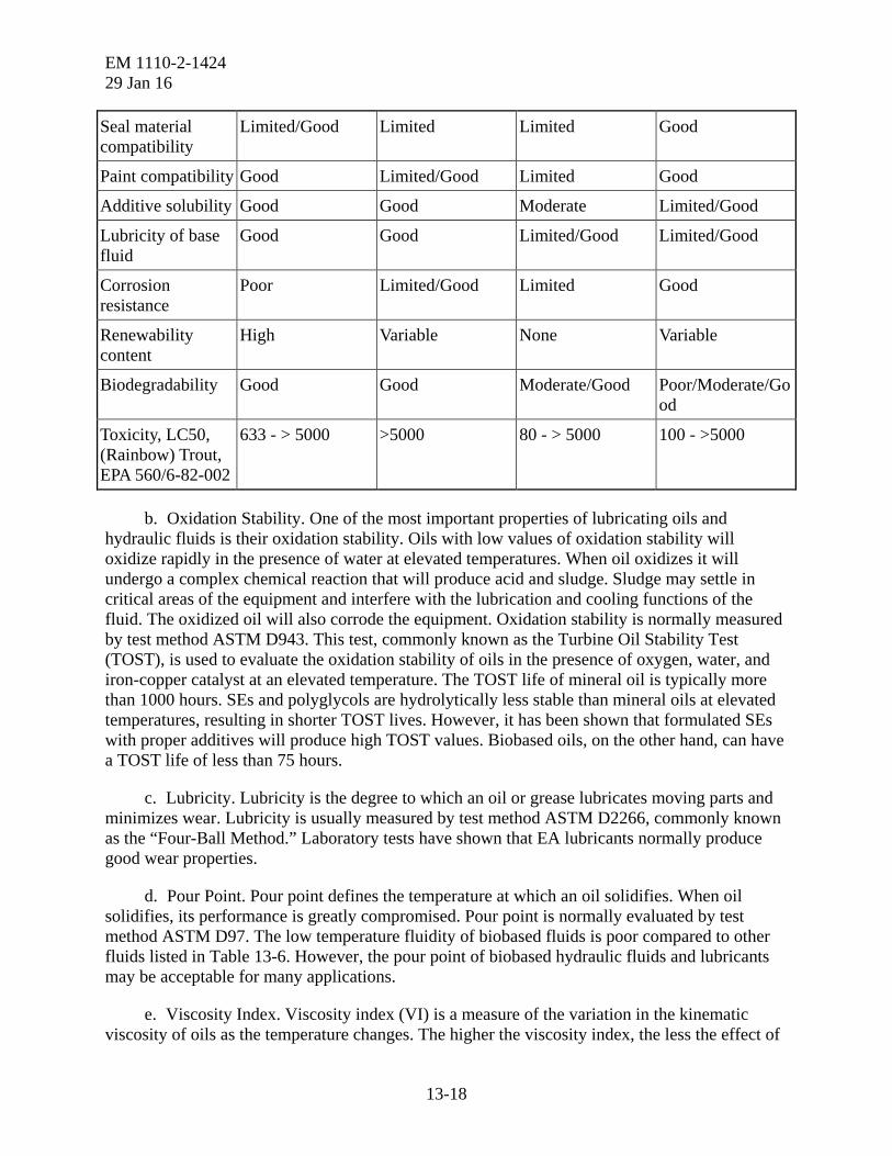
EM 1110-2-1424 29 Jan 16
13-18
Seal material compatibility
Limited/Good Limited Limited Good
Paint compatibility Good Limited/Good Limited Good
Additive solubility Good Good Moderate Limited/Good
Lubricity of base fluid
Good Good Limited/Good Limited/Good
Corrosion resistance
Poor Limited/Good Limited Good
Renewability content
High Variable None Variable
Biodegradability Good Good Moderate/Good Poor/Moderate/Good
Toxicity, LC50, (Rainbow) Trout, EPA 560/6-82-002
633 - > 5000 >5000 80 - > 5000 100 - >5000
b. Oxidation Stability. One of the most important properties of lubricating oils and hydraulic fluids is their oxidation stability. Oils with low values of oxidation stability will oxidize rapidly in the presence of water at elevated temperatures. When oil oxidizes it will undergo a complex chemical reaction that will produce acid and sludge. Sludge may settle in critical areas of the equipment and interfere with the lubrication and cooling functions of the fluid. The oxidized oil will also corrode the equipment. Oxidation stability is normally measured by test method ASTM D943. This test, commonly known as the Turbine Oil Stability Test (TOST), is used to evaluate the oxidation stability of oils in the presence of oxygen, water, and iron-copper catalyst at an elevated temperature. The TOST life of mineral oil is typically more than 1000 hours. SEs and polyglycols are hydrolytically less stable than mineral oils at elevated temperatures, resulting in shorter TOST lives. However, it has been shown that formulated SEs with proper additives will produce high TOST values. Biobased oils, on the other hand, can have a TOST life of less than 75 hours.
c. Lubricity. Lubricity is the degree to which an oil or grease lubricates moving parts and minimizes wear. Lubricity is usually measured by test method ASTM D2266, commonly known as the “Four-Ball Method.” Laboratory tests have shown that EA lubricants normally produce good wear properties.
d. Pour Point. Pour point defines the temperature at which an oil solidifies. When oil solidifies, its performance is greatly compromised. Pour point is normally evaluated by test method ASTM D97. The low temperature fluidity of biobased fluids is poor compared to other fluids listed in Table 13-6. However, the pour point of biobased hydraulic fluids and lubricants may be acceptable for many applications.
e. Viscosity Index. Viscosity index (VI) is a measure of the variation in the kinematic viscosity of oils as the temperature changes. The higher the viscosity index, the less the effect of

EM 1110-2-1424 29 Jan 16
13-19
temperature on its kinematic viscosity. VI is measured by test method ASTM D2270. As the data in Table 13-6 show, the VI of most EA fluids meets or exceeds the VI of petroleum-based fluids.
f. Foaming. The tendency of oils to foam can be a serious problem in lubricating and hydraulic systems. The lubrication and hydraulic properties of oils are greatly impeded by excessive foaming. Foaming characteristics of oils are usually determined by test method ASTM D892. Laboratory tests have shown that most formulated EA fluids do not have foaming problems. This should be verified with the manufacturer.
g. Paint Compatibility. Some common paints used in fluid systems are incompatible with many EA fluids especially PAG lubricants. When it is anticipated that EA fluids may be used in a fluid system, the use of epoxy resin paints should be used to eliminate potential compatibility problems.
h. Elastomeric Seal Compatibility. Polyurethane seals should not be used with EA fluids. Instead, the use of Viton and Buna-N (low to medium nitrile) is recommended. EA fluids are compatible with steel and copper alloys and provide excellent rust protection. The fluid manufacturer must be consulted for specific compatibility data for each material encountered in the application.
i. Degradability. EA lubrication fluids are especially susceptible to degradation caused by water. Since EA fluids are biodegradable, they will break down in the presence of water and bacteria. Moisture traps in breather intakes and other equipment modifications that will keep moisture out of the system should be considered. EA fluids should be periodically monitored to ensure that biodegradation is not occurring. Water levels in the fluid and system need to be kept to an absolute minimum and should never exceed 500 ppm.
13-9. Changing from Conventional to EA Lubricants.
a. Plant owners and operators considering a change to biodegradable lubricants and hydraulic fluids should, above all, be aware that these products are not identical to conventional mineral oil products. Furthermore, the EA fluids are not necessarily equal to one another. It is important to make a thorough assessment of the requirements of the specific application to determine whether a substitution can be made, and whether any compromises in quality or performance will be compatible with the needs of the user. Switching to EA products may require special considerations, measures, or adaptations to the system.
b. Some commercially available synthetic ester and biobased lubricants meet the requirements of nontoxicity and biodegradability. However, the compatibility of these fluids with existing materials encountered in the application, such as paints, filters, and seals, must be evaluated. This includes a testing program if necessary. The fluid manufacturer must be consulted for specific compatibility data for each material of construction. The manufacturer of the existing equipment must be consulted, especially when the equipment is still under warranty.
c. Extreme care must be taken when selecting an EA oil or grease for an application. Product availability may be impacted due to the dynamic nature of developing standards and environmental requirements. EA lubricating oils should not be used in hydroelectric turbine

EM 1110-2-1424 29 Jan 16
13-20
applications, such as bearing oil, runner hub oil, or governor oil, until extensive tests are performed. It is recommended that the Corps of Engineers Hydroelectric Design Center be consulted before the initial purchase of any EA fluids and greases for hydropower applications.
d. Accelerated fluid degradation at high temperature, change of performance characteristics at low temperature, and possible new filtration requirements should be investigated carefully. The oxidation rate of vegetable-based EA lubricants increases markedly above 179.6 °F (82 °C), and lengthy exposure at the low temperature can cause some products to gel. Filters should be checked after 50 hours of operation, as vegetable oil tends to remove mineral oil deposits from the system and carry them to the filters.
e. On a hydraulic power system, when changing over to EA lubricants, the system should be thoroughly drained of the mineral oil and, if possible, flushed. Flushing is mandatory if diesel engine oil was the previous hydraulic fluid. This will avoid compromising the biodegradability and low toxicity of the EA fluids. Disposal of the used fluids should be in accordance with applicable environmental regulations and procedures. More frequent filter changes may be necessary. Moisture scavengers may be necessary on breather intakes to keep water content in the lubricant low. Temperature controls for both upper and lower extremes may need to be added to the system. Redesign of hydraulic systems to include larger reservoirs may be necessary to deal with foaming problems. The use of stainless steel components to protect against corrosion may be necessary. To maximize the life of a biodegradable hydraulic oil in service, the following characteristics should be monitored regularly, with warning limits:
• Viscosity: +10%.
• Oxidation (TAN): +2mg KOH/g.
• Water content: >500ppm.
f. The number of manufacturers who produce EA hydraulic fluids, lubricating oils, and greases continues to expand. Names of the manufacturers include some well known companies that have marketed lubricants for many years as well as a large number of smaller companies that appear to specialize in EA products. Some of these companies also market specialty EA products such as gear oils, wire rope lubricants, air tool lubricants, and cutting and tapping fluids. EA turbine oils exist; however, to date, none of the oil suppliers has recommended these products for hydroelectric power plants. It is important for the end users to use due diligence when considering an EA fluid. This includes understanding the Federal, state, local, and tribal laws and regulations. Other considerations include:
• Understand the basics behind EA fluids, standards, and classifications.
• Ask questions of the system manufacturer and the fluid supplies.
• Talk to suppliers of the different types of fluids (SE, PAG, PAO, vegetable oils) to determine if that fluid is right for the intended application (more than one type of fluid may work).
• Require the fluid supplier to provide documentation from independent laboratories/testing companies.
• Consider the overall and lifecycle costs (including potential savings from fines).

EM 1110-2-1424 29 Jan 16
13-21
• Ensure the fluid supplier is a reputable company.
• Most importantly, obtain the approval from the system manufacturer for the use of the EA lubricant.
13-10. Selecting an Environmentally Acceptable Fluid. Selecting an EA hydraulic fluid to replace a fluid, or to commission a new system, is not a task that should be taken lightly. There is a wealth of information and misinformation available on EA fluids. The EA fluid industry is growing, and as such, there many choices when it comes to a new EA fluids. Some of the products available are truly “environmentally acceptable,” while other products only make those claims. Below is a summary of important considerations when evaluating an EA fluid:
a. System Requirements and Compatibility. Consult with the system manufacturer to determine all of the physical characteristics/parameters the fluid for that system shall require and if the proposed fluid is acceptable. Other considerations include:
• Consult with the system manufacturer and fluid provider to ensure the operating environment is suitable for the fluid.
• Consult with the system manufacturer to determine if ALL of the seals in the system are compatible with the proposed fluid.
• If the system is still under warranty, ensure the new fluid will not void the remaining warranty.
• Examine the tank/reservoir coating system and determine if the fluid is compatible.
• Obtain written approval from the system manufacturer indicating that the proposed fluid is compatible with the system, reservoir, and seals, and that the physical and performance properties are within the requirements system.
• Coordinate with the system manufacturer and the fluid provider on the proper flushing procedures.
• If commissioning a new system, require the system manufacturer to factory/bench test the system with the proposed EA fluid. The manufacturer should provide a full test report including oil analysis both before and after testing.
b. Environmental Properties. All testing regarding environmental properties should be performed by independent laboratories/testing companies. Documentation should be provided for all required tests. This includes tests for biodegradability, toxicity, and sheen generation. Provide a list of the chemical compounds in the fluid and ensure that no heavy metals are present.
c. Costs and Maintenance Considerations. One particular area of concern for manufacturers and end users is fluid lifetime. A significant question is whether the EA lubricant last as long as conventional mineral oils. In some cases, high performance EA lubricants can actually offer the benefit of longer life. The cost of EA fluids currently range from 1.5 to 4 times that of a regular grade petroleum-based hydraulic fluid. This is similar for other types of EA lubricants. Costs can vary from fluid manufacturer and volume required. Despite the higher initial costs for EA hydraulic fluids compared to petroleum-based fluids, there can be significant savings in cleanup costs, when compared to cleanup costs for petroleum-based hydraulic fluids.

EM 1110-2-1424 29 Jan 16
13-22
In some instances, if an accidental discharge occurs, the fines may be reduced or eliminated if the issuing agency is aware (or is made aware) that the fluid is EA and the impact on the environment is minimal. In addition, some EA hydraulic fluids have a longer life expectancy than a traditional mineral oil, and therefore the lifecycle costs over time may be reduced. To reduce costs, users should:
• Obtain a quote(s) from the suppliers.
• Determine if additional fluid is necessary for proper system flushing and ensure that fluid cost is included.
• Consult with the suppliers on the life expectancy of the fluid and recommended intervals between fluid changes, filter changes, dryer/breather changes, etc.
• Develop a lifecycle cost analysis to compare the fluid(s) to the conventional fluid over a fix period of time.
• Include periodically scheduled fluid analysis as part of the maintenance program.
13-11. Sheen Generation. The sheen generating properties of hydraulic fluid and other lubricating oils and how they relate to the environment is a hotly debated topic. Some argue that oil sheens on the surface of the water allow for faster detection of a spill/leak/problem and help determine the source and severity of the oil spill. Also, the oil sheen has the potential to be contained with booms and recovered, whereas non-sheening water soluble oils may directly enter the water column after which they cannot be recovered. Others argue that a non-sheen oil may not remain on the surface of the water where it has the potential to coat the feathers of fowl or a mammal coming to the surface for air, which can hinder their ability to breathe and survive. Additionally, there are applications where, due to the nature of the service (i.e., stern tube, submerged bearing, etc.), the oil-to-sea interface will only seep small/limited amounts of oil. In these instances, a non-sheening environmentally acceptable fluid may be desirable.
a. Regardless of the arguments for or against sheen generation, the end user must be aware of the Federal regulations relating to oil discharge. The CWA and the Oil Pollution Act of 1990 (OPA 90) prohibits the discharge of oil into the waters of the United States in quantities that may be harmful. Alsp, 40 CFR Part 110.3(b) defines “quantities that may be harmful” as those causing a film or sheen on or discoloration of the surface of the water or adjoining shorelines or cause a sludge or emulsion to be deposited beneath the surface of the water or on adjoining shorelines. The current USEPA VGP allows for discharges of lubricants from normal operations in amounts that are not harmful (per 40 CFR Part 110). In addition to the Federal statutes, the discharge of oil must also be in accordance with appropriate state, local, and/or tribal governments.
b. As the regulations read above, any oil discharge or spill that results in a sheen must be reported to the appropriate authorities. If the discharge or spill does not create a sheen, it still is reportable if it created sludge or emulsion below the water. Operators and supervisors must be aware of the regulations and the requirements to report any discharge of oil in quantities that may be harmful.

EM 1110-2-1424 29 Jan 16
13-23
c. Although employing a “non-sheening” EA hydraulic fluid or lubricating oil may be desirable over a sheening type, this factor should not be considered in the determination of the fluid’s EA classification. It is the responsibility of the floating plant and facility operators to evaluate their operations and determine the desirable sheen characteristics. Considerations may include the location of the equipment, open or closed systems, expected operational seepage, spill potential, the level of monitoring on the system, the operating area, and other environmental factors. If a non-sheen EA hydraulic fluid is required by the operators, it shall meet sheen requirements as defined by the “Static Sheen Test.” Sheen test requirements are defined in 40 CFR 435, Subpart A, Appendix 1, Part 1, Scope and Application, which states:
This method is to be used as a compliance test for the “no discharge of free oil” requirement for discharges of drilling fluids, drill cuttings, produced sand, and well treatment, completion and workover fluids. “Free oil” refers to any oil contained in a waste stream that when discharged will cause a film or sheen on a discoloration of the surface of the receiving water.
d. Sheen Generation shall pass the USEPA Static Sheen Test as described in 40 CFR 435, Subpart A, Appendix 1. Appendix 1, Part 8.6, of the referenced CFR provides requirements regarding sheen detection and growth. These requirements are:
(1) Detection of “free oil”
Detection of a “silvery” or “metallic” sheen or gloss, increased reflectivity, visual color, iridescence, or an oil slick on the water surface of the test container surface shall constitute a demonstration of “free oil” …
(2) Sheen growth
If an oil sheen or slick occurs on less than one-half of the surface area after the sample is introduced to the test container, observations will continue for up to 1 hour. If the sheen or slick increases in size and covers greater than one-half of the surface area of the test container during the observation period, the discharge of the material shall cease. If the sheen or slick does not increase in size to cover greater than one-half of the test container surface area after 1 hour of observation, discharge may continue and additional sampling is not required.
If a sheen or slick occurs on greater than one-half of the surface area of the test container after the test material is introduced, discharge of the tested material shall cease. The permittee may retest the material causing the sheen or slick. If subsequent tests do not result in a sheen or slick covering greater than one-half of the surface area of the test container, discharge may continue.
13-12. Transformer Oils.
a. Transformer oils are used as a dielectric lubricant in transformers. A transformer oil is not only an insulator, but is also a coolant. Therefore, to successfully use EA fluids in large transformers such as that shown in Figure 13-2, care must be taken to ensure that the thermal properties of these dielectrics are not different enough to affect the operation of the transformer. EA fluids for transformers include natural esters and vegetable oil. For the past few years, the

EM 1110-2-1424 29 Jan 16
13-24
U.S. Department of the Interior has tested the effectiveness of electrical transformers that use vegetable oil instead of mineral oil to boost power production while lowering the threat of fires and toxic spills. Transformers need the oil as an insulating and cooling agent. Polychlorinated biphenyls (PCBs) were once used extensively for transformer lubrication. However, PCBs are highly toxic. Petroleum-based mineral oil replaced PCBs, but that also poses a risk for installations on waterways. One manufacturer of dielectric transformer fluid (Cargill) makes the fluid out of soybeans. Other companies make it from sunflower seeds and other vegetables. However, whatever the base material, vegetable oil fluids do not catch fire or overheat the way mineral oil does, and they biodegrade naturally within weeks if spilled, something that petroleum-based mineral oil does not do.
b. Vegetable oil-filled transformers currently make up only about 10% of the transformers on the U.S. market. However, that number is expected to grow substantially in the future. The current number of transformers in the United States that use vegetable oil fluid is over half a million. They range from the small transformers on power poles to massive transformers at power plants. With vegetable oil insulation, lightning strikes to transformers may no longer lead to fires. Spills will be less toxic. Vegetable-based oil transformers can also run at higher temperatures than mineral oil-based transformers. This may help prevent summertime brownouts in the summer. Studies show that vegetable oils catch fire at roughly 680 °F (360 °C) while mineral oil catches fire at roughly 335 °F (168 °C). The use of vegetable-based oil-filled transformers should be evaluated for all new transformer installations at USACE facilities on waterways.
Figure 13-2. Transformer at a Power Plant.