lab 2: introduction to free range routing (frr)
TRANSCRIPT

BORDER GATEWAY PROTOCOL
Lab 2: Introduction to Free Range Routing (FRR)
Document Version: 02-18-2020
Award 1829698 “CyberTraining CIP: Cyberinfrastructure Expertise on High-throughput
Networks for Big Science Data Transfers”

Lab 2: Introduction to Free Range Routing (FRR)
Page 2
Contents Overview ............................................................................................................................. 3
Objectives............................................................................................................................ 3
Lab settings ......................................................................................................................... 3
Lab roadmap ....................................................................................................................... 3
1 Introduction to FRR ..................................................................................................... 3
1.1 FRR architecture ................................................................................................... 4
1.2 FRR and Mininet integration ................................................................................ 5
2 Lab topology................................................................................................................ 6
2.1 Lab settings........................................................................................................... 6
2.2 Open the topology ............................................................................................... 7
2.3 Load the configuration file ................................................................................... 8
2.4 Run the emulation ................................................................................................ 9
2.5 Verify the configuration ..................................................................................... 10
2.6 Test connectivity between end-hosts ................................................................ 14
3 Configure a routing protocol .................................................................................... 14
3.1 Enable a routing daemon ................................................................................... 15
3.2 Configure static route ........................................................................................ 16
3.3 Verify the configuration ..................................................................................... 18
4 Test connectivity and verify routes between end-hosts .......................................... 19
References ........................................................................................................................ 20

Lab 2: Introduction to Free Range Routing (FRR)
Page 3
Overview This lab is an introduction to Free Range Routing (FRR), which is a routing software suite that provides TCP/IP based routing services with routing protocols support. FRR also encompasses tasks such as exchanging routing information with other routers, making routing and policy decisions and, managing packet forwarding. In this lab, you will explore FRR architecture, load basic configuration and conduct connectivity tests within a simple topology. Objectives By the end of this lab, students should be able to:
1. Understand the architecture of FRR. 2. Run FRR daemons in an emulated environment. 3. Enable routing features using the router’s command line. 4. Navigate into FRR terminal using administrative commands. 5. Load a configuration file into the router. 6. Perform a connectivity test between end hosts.
Lab settings The information in Table 1 provides the credentials of the machine containing Mininet.
Table 1. Credentials to access Client1 machine.
Device
Account
Password
Client1 admin password
Lab roadmap This lab is organized as follows:
1. Section 1: Introduction to FRR. 2. Section 2: Lab topology. 3. Section 3: Configure a routing protocol. 4. Section 4: Test connectivity and verify routes between end-hosts.
1 Introduction to FRR Implementing IP routing usually involves buying expensive and vertically integrated equipment from specific companies. This approach has limitation such as the cost of the

Lab 2: Introduction to Free Range Routing (FRR)
Page 4
hardware, closed source software and the training required to operate and configure the devices. Networking professionals, operators and researchers sometimes are limited by the capabilities of such routing products. Moreover, combining routing functionalities with existing open source software packages is usually constrained by the number of separate devices that can be deployed. For example, operators could be interested in collecting some information about the behavior of routing devices, process them, and make them available. Therefore, in order to achieve such capabilities, additional storage and scripting capacities are required. Such resources are not available in existing routing products. On the other hand, researchers may be interested on developing routing protocols by extending an existing one without writing a complete implementation from scratch. FRR suite1 is a package of Unix/Linux software that implements common network routing protocols, such as Routing Information Protocol4 (RIP), Open Shortest Path First5 (OSPF), Border Gateway Protocol6 (BGP) and Intermediate System to Intermediate System IS-IS7. The package also includes a routing information management process, to act as intermediary between the various routing protocols and the active routes installed with the kernel. A library provides support for configuration and an interactive command-line interface. The routing protocols supported by FRR, can be extended to enable experimentation, logging, or custom processing. In addition, libraries and kernel daemon provide a framework to facilitate the development of new routing protocol daemons. A wide range of functionalities can be attained by combining other software packages to allow the integration into a single device as well as enabling innovative solutions to networking problems. FRR is distributed under General Public License v2.0 (GPLv2). The community of operators, vendors, non-profits and researchers are interested in increasing the visibility of FRR, and a potential path to wider testing and deployment of proposed modifications to routing protocols, or new routing protocols. 1.1 FRR architecture
FRR takes a different approach compared to traditional routing software which, consists of a single process program that provides all the routing protocol functionalities. FRR is composed by a suite of daemons that work together to build a routing table. Each routing protocol is implemented in its own daemon. These daemons exchange information through another daemon called zebra, which is responsible for encompassing routing decisions and managing the dataplane. Since all the protocols are running independently, this architecture provides high resiliency, that means that an error, crash or exploit in one protocol daemon will generally not affect the other protocols. It is also flexible and extensible since the modularity makes it easy to implement new protocols and append them to the suite1. Additionally, each daemon implements a plugin system allowing new functionality to be loaded at runtime.

Lab 2: Introduction to Free Range Routing (FRR)
Page 5
Figure 1 illustrates FRR architecture. It consists of a set of processes communicating via Inter-process Communication (IPC) protocol. This protocol refers to the mechanism provided by an operating system (OS) to allow the management of shared data between different processes. Network routing protocols such as BGP, OSPF and IS-IS are implemented in processes such as bgpd, ripd, ospfd, ldpd, etc. These processes are daemons that implement routing protocols e.g., the BGP daemon is implemented by the bgpd process, the RIP daemon is implemented by the ripd process and so on. Another daemon, called zebra, acts as an intermediary between the kernel’s forwarding plane and the routing protocol processes. Additionally, an interactive command-line tool called vtysh allows these processes to be monitored and configured. The vtysh command-line tool communicates with other processes via a simple string passing protocol, where the strings are essentially identical to the commands entered. The zebra process is a fundamental part of FRR architecture. Its purpose is to maintain a backup of packet forwarding state, such as the network interfaces and the table of currently active routes. The currently active routes are also referred to as the Forwarding Information Base (FIB) 2. Usually, the kernel manages packet forwarding therefore, kernel maintains these. The zebra process also collects routing information from the routing protocol processes and stores these, together with its shadow copy of the FIB, in its own Routing Information Base (RIB)2 whereas, static routes are also configured. The zebra process then is responsible for selecting the best route from all those available for a destination and updating the FIB3. Additionally, information about the current best routes may be distributed to the protocol daemons. The zebra process maintains the routing daemons updated if any change occurs in the network interface state.
Figure 1. FRR architecture.
1.2 FRR and Mininet integration
Mininet is a network emulator which runs collection of end-hosts, switches, routers and links on a single Linux kernel5. Mininet provides network emulation, allowing all network software at any layer to be simply run as is, i.e. nodes run the native network software of the physical machine. Hence, the set of commands provided by FRR are inherited and can be run using Mininet’s command-line interface. This feature allows the user to run and

Lab 2: Introduction to Free Range Routing (FRR)
Page 6
configure FRR in the emulated routers. FRR is production-ready but we are using it in an emulated environment. 2 Lab topology Consider Figure 2. The lab topology is organized in two networks, Network 1 and Network 2. Both networks have the following elements: a router to specify the network, a switch that defines a Local Area Network (LAN) and lastly, a host aimed to test end-to-end connectivity
Figure 2. Lab topology.
2.1 Lab settings
Routers and hosts are already configured according to the IP addresses shown in Table 2.
Table 2. Topology information.
Device Interface IIP Address Subnet Default gateway
r1
r1-eth0 192.168.1.1 /24 N/A
r1-eth1 192.168.12.1 /30 N/A
r2
r2-eth0 192.168.2.1 /24 N/A
r2-eth1 192.168.12.2 /30 N/A
h1 h1-eth0 192.168.1.10 /24 192.168.1.1
h2 h2-eth0 192.168.2.10 /24 192.168.2.1

Lab 2: Introduction to Free Range Routing (FRR)
Page 7
2.2 Open the topology
In this section, you will open MiniEdit9 and load the lab topology. MiniEdit provides a Graphical User Interface (GUI) that facilitates the creation and simulation of network topologies in Mininet. This tool has additional capabilities such as: configuring network elements (i.e IP addresses, default gateway), save the topology and export a layer 2 model. Step 1. A shortcut to Miniedit is located on the machine’s Desktop. Start Miniedit by clicking on Miniedit’s shortcut. When prompted for a password, type password.
Figure 3. MiniEdit shortcut.
Step 2. On Miniedit’s menu bar, click on File then open to load the lab’s topology. Open the Lab2.mn topology file stored in the default directory, /home/frr/BGP_Labs/lab2 and click on Open.
Figure 4. MiniEdit’s open dialog.
Figure 5 shows the topology used in this lab. In order to configure the interfaces, you will execute a script that will load the configuration on the routers.

Lab 2: Introduction to Free Range Routing (FRR)
Page 8
Figure 5. Mininet’s topology.
2.3 Load the configuration file
At this point the topology is loaded however, the interfaces are not configured. In order to assign IP addresses to the devices’ interfaces, you will execute a script that loads the configuration to the routers and end devices.
Step 1. Click on the icon below to open Linux’s terminal.
Figure 6. Opening Linux terminal.
Step 2. Click on the Linux’s terminal and navigate into BGP_Labs/lab2 directory by issuing the following command. This folder contains a configuration file and the script responsible for loading the configuration. The configuration file will assign the IP addresses to the routers’ interfaces. The cd command is short for change directory followed by an argument that specifies the destination directory. cd BGP_Labs/lab2

Lab 2: Introduction to Free Range Routing (FRR)
Page 9
Figure 7. Entering the BGP_Labs/lab2 directory.
Step 3. To execute the shell script, type the following command. The argument of the program corresponds to the configuration zip file that will be loaded in all the routers in the topology. ./config_loader.sh lab2_config.zip
Figure 8. Executing the shell script to load the configuration.
Step 4. Type the following command to exit the Linux terminal. exit
Figure 9. Exiting from the terminal.
2.4 Run the emulation
In this section, you will run the emulation and check the links and interfaces that connect the devices in the given topology.
Step 1. At this point host h1 and host h2 interfaces are configured. To proceed with the emulation, click on the Run button located in lower left-hand side.

Lab 2: Introduction to Free Range Routing (FRR)
Page 10
Figure 10. Starting the emulation.
Step 2. Issue the following command to display the interface names and connections. links
Figure 11. Displaying network interfaces.
In Figure 11, the link displayed within the gray box indicates that interface eth2 of switch s1 connects to interface eth0 of host h1 (i.e., s1-eth2<->h1-eth0). 2.5 Verify the configuration
In the following steps, you will verify the IP address to the hosts following Table 2 as the IP addresses are already configured for you. You can verify the IP addresses assigned to each host and the routing table of each router to see if the configuration is correct according to the table. Step 1. Hold right-click on host h1 and select Terminal. This opens the terminal of host h1 and allows the execution of commands on that host.

Lab 2: Introduction to Free Range Routing (FRR)
Page 11
Figure 12. Opening a terminal on host h1.
Step 2. In host h1 terminal, type the command shown below to verify that the IP address was assigned successfully. You will corroborate that host h1 has two interfaces, h1-eth0 configured with the IP address 192.168.1.10 and the subnet mask 255.255.255.0. ifconfig
Figure 13. Output of ifconfig command.
Step 3. On host h1 terminal, type the command shown below to verify that the default gateway IP address is 192.168.1.1. route

Lab 2: Introduction to Free Range Routing (FRR)
Page 12
Figure 14. Output of route command.
Step 4. In order to verify host 2 default route, proceed similarly by repeating from step 1 to step 3 in host h2 terminal. Similar results should be observed. Step 5. In order to verify router r1, hold right-click on router r1 and select Terminal.
Figure 15. Opening a terminal on router r1.
Step 6. In this step, you will start zebra daemon, which is a multi-server routing software which provides TCP/IP based routing protocols. Further details about zebra daemon is provided in Section 1. In order to start the zebra, type the following command: zebra
Lab 2: Introduction to Free Range Routing (FRR)
Page 13
Figure 16. Starting zebra daemon.
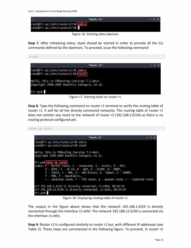
Step 7. After initializing zebra, vtysh should be started in order to provide all the CLI commands defined by the daemons. To proceed, issue the following command: vtysh
Figure 17. Starting vtysh on router r1.
Step 8. Type the following command on router r1 terminal to verify the routing table of router r1. It will list all the directly connected networks. The routing table of router r1 does not contain any route to the network of router r2 (192.168.2.0/24) as there is no routing protocol configured yet. show ip route
Figure 18. Displaying routing table of router r1.
The output in the figure above shows that the network 192.168.1.0/24 is directly connected through the interface r1-eth0. The network 192.168.12.0/30 is connected via the interface r1-eth1.
Step 9. Router r2 is configured similarly to router r1 but, with different IP addresses (see Table 2). Those steps are summarized in the following figure. To proceed, in router r2

Lab 2: Introduction to Free Range Routing (FRR)
Page 14
terminal issue the commands depicted below. At the end, you will verify all the directly connected networks of router r2.
Figure 19. Displaying routing table of router r2.
2.6 Test connectivity between end-hosts
In this section you will run a connectivity test between host 1 and host 2. You will notice that there is no connectivity because there is no routing protocol configured in the routers. Step 1. In host h1 terminal, type the command shown below. Notice that according to Table 1, the IP address 192.168.2.10 is assigned to host h2. To stop the test press ctrl+c. ping 192.168.2.10
Figure 20. Connectivity test between host h1 and host h2.
3 Configure a routing protocol In the previous section you used a script to assign the IP addresses to all devices’ interfaces then, you performed an unsuccessful connectivity test. In this section you will configure a routing protocol in order to establish a connection between the two networks. You will configure static routing in router r1 and router r2 such that host h1 can reach out

Lab 2: Introduction to Free Range Routing (FRR)
Page 15
host h2 and vice versa. First, you will initialize the daemon that enables static route configuration then, you will configure static routes in router r1 and router r2. Specifically, static routes are configured by setting the destination network and the IP address of the next hop. Finally, you will verify the configuration. The syntax to configure static routes in FRR router is as follows: ip route <NETWORK> <GATEWAY>
• ip route: is used to create or modify routing tables.
• NETWORK: specifies the destination network.
• GATEWAY: determines the next hop IP address. 3.1 Enable a routing daemon
In this section you will run the daemon that enables static routing configuration. Step 1. In router r1 terminal, type the following command to exit from FRR terminal. exit
Figure 21. Exiting the vtysh session.
Step 2. Now issue the following command on router r1 terminal to enable the static routing daemon. staticd

Lab 2: Introduction to Free Range Routing (FRR)
Page 16
Figure 22. Starting static routing daemon.
Now, the static routing daemon is running and is ready to set up a configuration.
3.2 Configure static route
In this section, you will configure the static routes on router r1 and router r2. This configuration will establish a connectivity between the networks 192.168.1.0/24 and 192.168.2.0/24. Step 1. In order to enter to router r3 terminal, issue the following command: vtysh
Figure 23. Starting vtysh on router r1.

Lab 2: Introduction to Free Range Routing (FRR)
Page 17
Step 2. To enable router r1 configuration mode, issue the following command: configure terminal
Figure 24. Enabling configuration mode on router r1.
Step 3. In order to configure a static route to reach out the network 192.168.2.0/24 thru the IP address 192.168.12.2, type the following command: ip route 192.168.2.0/24 192.168.12.2
Figure 25. Configuring a static route on router r1.
Step 4. To exit from configuration mode, issue the following command: exit
Figure 26. Exiting from configuration mode.
Step 5. The figure below summarizes the steps that must be followed in router r2 terminal in order to configure static route. From the perspective of router r2 the network 192.168.1.0 is reachable via the IP address 192.168.12.1.

Lab 2: Introduction to Free Range Routing (FRR)
Page 18
Figure 27. Configuring static routing on router r2.
3.3 Verify the configuration
In this section, you will verify the configuration on router r1 and router r2. Step 1. In router r1 terminal, type the following command to show the routing table entries. Notice that the network 192.168.2.0/24 is reachable via the IP address 192.168.12.2. The egress interface is r1-eth1: show ip route
Figure 28. Verifying the routing table of router r1.
Step 2. Similarly, in router r2 terminal, type the following command to show the routing table entries. Notice that the network 192.168.1.0/24 is reachable via the IP address 192.168.12.1. The egress interface is r2-eth1:

Lab 2: Introduction to Free Range Routing (FRR)
Page 19
show ip route
Figure 29. Verifying the routing table of router r2.
4 Test connectivity and verify routes between end-hosts In this section you will perform a connectivity test from host h1 to host h2. Additionally, you will check the details about the path that a packet takes from host h1, the source, to host h2, the destination. Step 1. On host h1 terminal type the following command. The IP address 192.168.2.10 corresponds to host h2: ping 192.168.2.10
Figure 30. Output of ping command on host h1.
Step 2. On host h1 terminal type the following command. Notice that it takes three hops to reach out the destination which, in this case is host h2.

Lab 2: Introduction to Free Range Routing (FRR)
Page 20
traceroute 192.168.2.10
Figure 31. Verifying the path details using traceroute command.
This concludes Lab 2. Stop the emulation and then exit out of MiniEdit and Linux terminal. References
1. Linux foundation collaborative projects, “FRR routing documentation”, 2017. [Online]. Available: http://docs.frrouting.org/en/latest/
2. P. Jakma, D. Lamparter. “Introduction to the quagga routing suite,” 2014, IEEE Network 28.
3. K. Ishiguro, “Gnu zebra,”. [Online]. Available: http://www. zebra. org (2002). 4. G. Malkin, “RIP Version 2,” RFC 2453 updated by RFC 4822, 1998. [Online].
Available: http://www.ietf.org/rfc/rfc2453.txt. 5. Mininet walkthrough. [Online]. Available: http://Mininet.org. 6. G. Malkin, R. Minnear, “RIPng for IPv6,” RFC 2080, 1997. [Online]. Available:
http://www.ietf.org/rfc/rfc2080.txt. 7. Y. Rekhter, T. Li, S. Hares, “A border gateway protocol 4 (BGP-4),” RFC 4271
updated by RFCs 6286, 6608, 6793, 2006. [Online]. Available: http://www.ietf.org/rfc/rfc4271.txt.
8. D. Oran, “OSI IS-IS intra-domain routing protocol,” RFC 1142, 1990. [Online]. Available: http://www.ietf.org/rfc/rfc1142.txt.
9. B. Lantz, G. Gee, “MiniEdit: a simple network editor for Mininet,” 2013. [Online]. Available: https://github.com/Mininet/Mininet/blob/master/examples.