lafert s.p.a. via j. f. kennedy, 43 hp series hp series_mk… · this gives the ability to engineer...
TRANSCRIPT

MKTG
-10-10
3/15
www.lafert.com
TECHNICAL CATALOGUE 2015
Lafert S.p.A. Via J. F. Kennedy, 43I-30027 San Donà di Piave (Venice), ItalyTel. +39 / 0421 229 611 | Fax +39 / 0421 222 [email protected]
TE
CH
NIC
AL
CA
TALO
GU
E 2
01
5 -
Hig
h P
erf
orm
an
ce M
oto
rs
IE4
HIGH PERFORMANCE MOTORSINTEGRAL DRIVE (HPI RANGE)
STAND ALONE MOTOR (HPS RANGE)
HP SERIES

TECHNICAL CATALOGUE MKTG-10-103/15Branches & Partners
Lafert GmbH Olgastraße 34/1 D - 73728 Esslingen - Germany Phone +49 / (0) 711 540 3095 + 7 Fax +49 / (0) 711 540 3098 [email protected]
Lafert Electric Motors Ltd. Unit 17 Orion Way Crewe, Cheshire CW1 6NGUnited Kingdom Phone +44 / (0) 1270 270 022 Fax +44 / (0) 1270 270 [email protected]
Lafert Moteurs S.A.S. L’Isle d’Abeau Parc de Chesnes 75, rue de Malacombe F - 38070 St. Quentin-Fallavier France Phone +33 / 474 95 41 01 Fax +33 / 474 94 52 28 [email protected]
Lafert Motores Eléctricos, S.L.Polígono Pignatelli, Nave 27 E - 50410 Cuarte de Huerva (Zaragoza) - SpainPhone +34 / 976 503 822 Fax +34 / 976 504 199 [email protected]
Lafert N.A. (North America)5620 Kennedy Road - Mississauga Ontario L4Z 2A9 - Canada Phone +1 / 800/661 6413 - 905/629 1939Fax +1 / 905/629 2852 [email protected]
Lafert Electric Motors (Australia)Factory 3, 117-123 Abbott Road,Hallam - VIC 3803 - AustraliaPhone +61 / (0)3 95 46 75 15Fax +61 / (0)3 95 47 93 [email protected]
Lafert Singapore Pte Ltd48 Hillview Terrace #02-08 Hillview Building - Singapore 669269 Phone +65 / 67630400 - 67620400Fax +65 / [email protected]
Lafert (Suzhou) Co., Ltd.No.3 Industrial Plant Building Yue Xi Phase 3,Tian E Dang Lu 2011, 15104 Wu ZhongEconomic Development Zone, Suzhou, ChinaPhone +86 / 512 6687 0618Fax +86 / 512 6687 [email protected]
brAKE MOTOrs
sErVO MOTOrs & DrIVEs
LIFT MOTOrs
AC MOTOrs - IE3, IE2
HIGH PErFOrMANCE MOTOrs - IE4

GENERAL INFORMATION 3PRODUCT RANGE 4MERGING TECHNOLOGIES 10 TECHNICAL DESCRIPTION 13Brief descriptionDefinitionsSTANDARDS AND REGULATIONS 14CONDITIONS OF INSTALLATION 18Electrical/mechanical tolerancesThermal protection and deratingDerating for ambient temperature,air pressure, running at low speedELECTRICAL DESIGN 21Galvanic isolation (PELV)Heart leakage currentOver voltage protectionMains supply interference/harmonicsMECHANICAL DESIGN 23 Degrees of protectionMounting arrangementsBearing lubrication and maintenanceCoolingVibrationMOTOR NAMEPLATE 27
HPI – INTEGRAL DRIVE 29DRIVE SPECIFICATIONS 30 PERFORMANCE DATA 32DIMENSIONS 37
HPS – STAND ALONE MOTOR 39PERFORMANCE DATA 40DIMENSIONS 45
CONTENTS

3GENERAL INFORMATION - Technical caTalogue 10-103/15
General information

4 GENERAL INFORMATION - Technical caTalogue 10-103/15
PRODUCT RANGE
MISSION
The Lafert Group, a leading European Motor Company, is committed to continuous growth by being the global leading manufacturer of customised engineered Electric Motors and Drives with specific focus on Industry Automation, Energy Saving, and Renewables.
The Lafert Group will strive to be the ideal partner in the Electric Motors and Drives industry through focus on meeting specific customer demands. Mutually beneficial partnerships are developed by continuous process improvements utilising state-of-the-art products and techniques by a skilled, motivated and professional workforce.
cuSTOM MADE, cuSTOM PHILOSOPHy
Lafert specializes in the design and manufacture of customized electric motors produced to meet specific applications and needs of individual customers. Over 90% of Lafert’s output is non-standard motors.
The control of the whole manufacturing process allows for any aspect of the motor to be modified. This gives the ability to engineer customized motors that fit the final application/work environment for maximum efficiency and reliability.
Lafert leverages over 50 years of experience in partnering with Global Companies from its 12 locations spread across Europe, North America, Asia and Australia.
ASYNCHRONOUS MOTORS, Three-phase Motors Premium Efficiency - IE3 and High Efficiency - IE2 customized to specific applications and OEM requirements
BRAKE MOTORS, Asynchronous Motors, DC and AC brake, for heavy duty applications
HP RANGE, Permanent Magnet Synchronous Motors and Drives, Super Premium Efficiency – IE4/IE5, IPM and SMPM technology, designed for HVAC applications
SERVO MOTORS & DRIVES, Brushless Servomotors and Drives for Industrial Automation
LIFT RANGE, Synchronous Gearless Machines for M.R.L. Elevators
5GENERAL INFORMATION - Technical caTalogue 10-103/15
PRODUCT RANGE
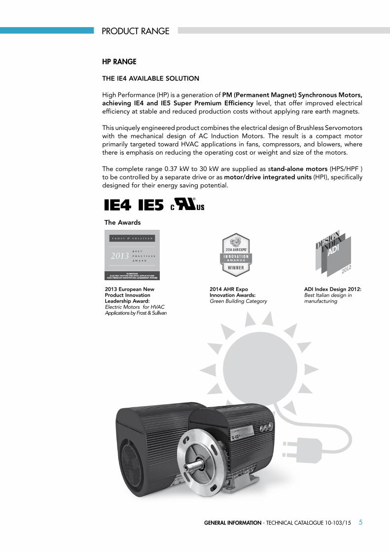
HP RANGE
THE IE4 AVAILABLE SOLUTION
High Performance (HP) is a generation of PM (Permanent Magnet) Synchronous Motors, achieving IE4 and IE5 Super Premium Efficiency level, that offer improved electrical efficiency at stable and reduced production costs without applying rare earth magnets.
This uniquely engineered product combines the electrical design of Brushless Servomotors with the mechanical design of AC Induction Motors. The result is a compact motor primarily targeted toward HVAC applications in fans, compressors, and blowers, where there is emphasis on reducing the operating cost or weight and size of the motors.
The complete range 0.37 kW to 30 kW are supplied as stand-alone motors (HPS/HPF ) to be controlled by a separate drive or as motor/drive integrated units (HPI), specifically designed for their energy saving potential.
The Awards
ADI Index Design 2012: Best Italian design in manufacturing
2014 AHR Expo Innovation Awards: Green Building Category
2013 European New Product Innovation Leadership Award: Electric Motors for HVAC Applications by Frost & Sullivan
IE4 IE5
6 GENERAL INFORMATION - Technical caTalogue 10-103/15
PRODUCT RANGE
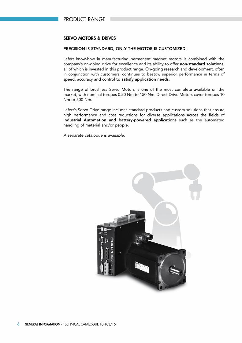
SERVO MOTORS & DRIVES
PRECISION IS STANDARD, ONLY THE MOTOR IS CUSTOMIZED!
Lafert know-how in manufacturing permanent magnet motors is combined with the company’s on-going drive for excellence and its ability to offer non-standard solutions, all of which is invested in this product range. On-going research and development, often in conjunction with customers, continues to bestow superior performance in terms of speed, accuracy and control to satisfy application needs.
The range of brushless Servo Motors is one of the most complete available on the market, with nominal torques 0.20 Nm to 150 Nm. Direct Drive Motors cover torques 10 Nm to 500 Nm.
Lafert’s Servo Drive range includes standard products and custom solutions that ensure high performance and cost reductions for diverse applications across the fields of Industrial Automation and battery-powered applications such as the automated handling of material and/or people.
A separate catalogue is available.
7GENERAL INFORMATION - Technical caTalogue 10-103/15
PRODUCT RANGE
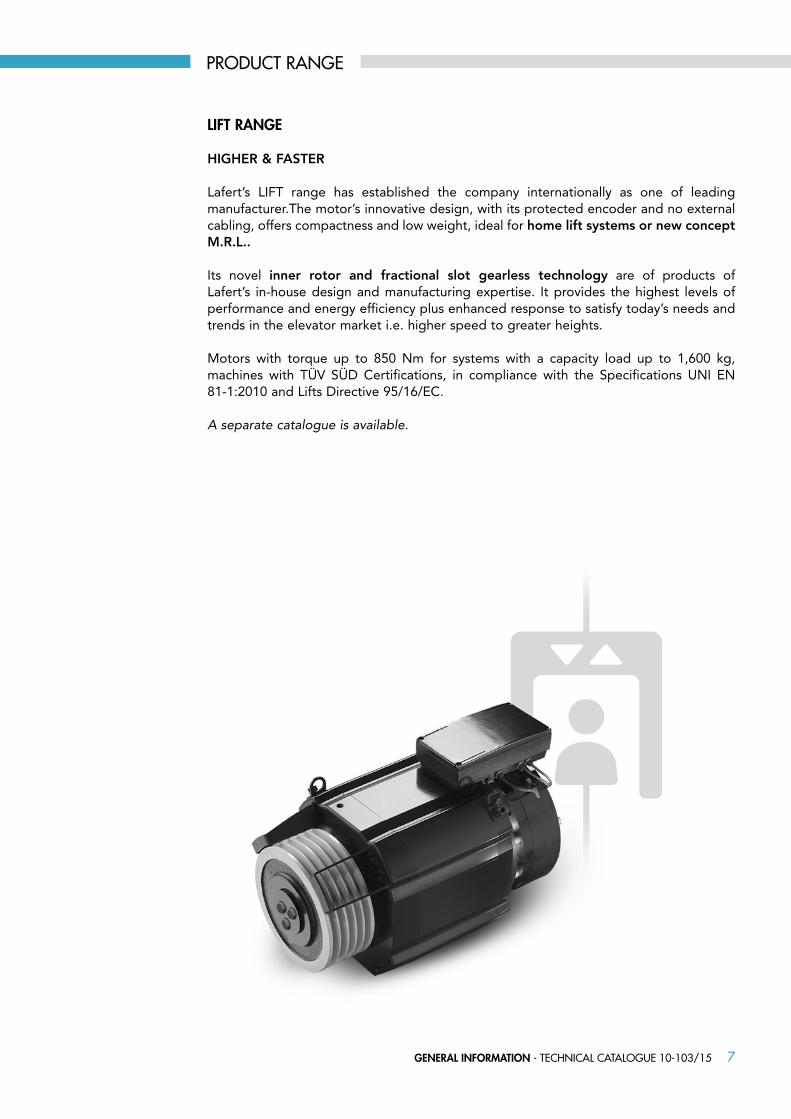
LIFT RANGE
HIGHER & FASTER
Lafert’s LIFT range has established the company internationally as one of leading manufacturer.The motor’s innovative design, with its protected encoder and no external cabling, offers compactness and low weight, ideal for home lift systems or new concept M.R.L..
Its novel inner rotor and fractional slot gearless technology are of products of Lafert’s in-house design and manufacturing expertise. It provides the highest levels of performance and energy efficiency plus enhanced response to satisfy today’s needs and trends in the elevator market i.e. higher speed to greater heights.
Motors with torque up to 850 Nm for systems with a capacity load up to 1,600 kg, machines with TÜV SÜD Certifications, in compliance with the Specifications UNI EN 81-1:2010 and Lifts Directive 95/16/EC.
A separate catalogue is available.

8 GENERAL INFORMATION - Technical caTalogue 10-103/15
PRODUCT RANGE
ASyNcHRONOuS MOTORS
HIGH EFFICIENCY, ENERGY SAVING
AC motors have a significant impact on the total energy operation cost for industrial, institutional and commercial buildings. Today, the major factor influencing the motor industry is energy efficiency driven by both increasingly demanding legislation and industry’s greater awareness of green issue responsibilities.
Premium Efficiency and High Efficiency Three-phase Motors meeting the requirements of IE3 and IE2 efficiency levels in accordance with IEC 60034-30-1:2014 and test method IEC 60034-2-1;2007.
Premium Efficiency IE3 motors provide compliance with the requirements of EU MEPS that has come into force January 1, 2015 and NEMA EPAct/EISA, which has been in force since December 2010 in the USA and January 2011 in Canada.
High Efficiency IE2 motors comply with the EU’s IE2 efficiency requirements, mandatory for all systems (motor <7.5kW + machinery) installed in the EU from January 2013 and for all motors 7.5 to 375kW put into operation with a variable speed drive (VSD) from January 2015.
A separate catalogue is available.
IE3IE2

9GENERAL INFORMATION - Technical caTalogue 10-103/15
PRODUCT RANGE
bRAkE MOTORS
EXTENSIVE CONFIGURATION OPTIONS MATCH MOTORS TO APPLICATIONS
The harsher the working environment the greater the demand on engineering standards, and non-standard then becomes the norm. Custom-design and engineering fulfil this need to give the reliability and performance demanded.
The Lafert Brake Motor series is engineered according to the client’s specification. Total control over all aspects of production permits multiple design options including flanges, shafts, brakes plus optimum resistance to external agents and offshore environments for paints, seals, and magnet surfaces.
The result is a range of AC motors with DC and AC brake, produced entirely in-house which incorporates Lafert’s own technical solutions for achieving robustness and performance, combined with the option for application-specific customization.
A separate catalogue is available.
IE1 IE2
10 GENERAL INFORMATION - Technical caTalogue 10-103/15
LEVERAGING LEADING-EDGE TECHNOLOGIES
High Performance Motors (HPS/HPI) are an innovative range of PM (Permanent Magnet) Synchronous Motors, achieving IE4 Super Premium Efficiency level that offer improved efficiency and reduced operating costs.
Lafert’s in house servo and AC induction motor design and manufacturing capabilities have facilitated the development of this uniquely engineered range of Permanent Magnet IE4 Synchronous Motors.
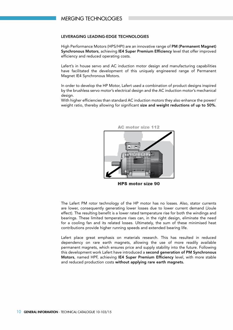
In order to develop the HP Motor, Lafert used a combination of product designs inspired by the brushless servo motor’s electrical design and the AC induction motor’s mechanical design.With higher efficiencies than standard AC induction motors they also enhance the power/weight ratio, thereby allowing for significant size and weight reductions of up to 50%.
The Lafert PM rotor technology of the HP motor has no losses. Also, stator currents are lower, consequently generating lower losses due to lower current demand (Joule effect). The resulting benefit is a lower rated temperature rise for both the windings and bearings. These limited temperature rises can, in the right design, eliminate the need for a cooling fan and its related losses. Ultimately, the sum of these minimised heat contributions provide higher running speeds and extended bearing life.
Lafert place great emphasis on materials research. This has resulted in reduced dependency on rare earth magnets, allowing the use of more readily available permanent magnets, which ensures price and supply stability into the future. Following this development work Lafert have introduced a second generation of PM Synchronous Motors, named HPF, achieving IE4 Super Premium Efficiency level, with more stable and reduced production costs without applying rare earth magnets.
MERGING TECHNOLOGIES
11GENERAL INFORMATION - Technical caTalogue 10-103/15
VALUE ADDED FEATURES & BENEFITS
The primary benefit offered by Lafert’s HP synchronous motor is the reduction in the life cycle cost of the motor. The combination of servo brushless and induction motor technology used for the development of this product gives it a high efficiency low noise design. Because of the higher efficiency, the product dissipates lower heat, which improves its operating life.
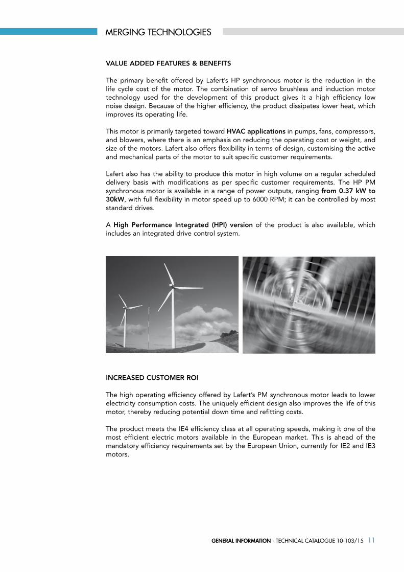
This motor is primarily targeted toward HVAC applications in pumps, fans, compressors, and blowers, where there is an emphasis on reducing the operating cost or weight, and size of the motors. Lafert also offers flexibility in terms of design, customising the active and mechanical parts of the motor to suit specific customer requirements.
Lafert also has the ability to produce this motor in high volume on a regular scheduled delivery basis with modifications as per specific customer requirements. The HP PM synchronous motor is available in a range of power outputs, ranging from 0.37 kW to 30kW, with full flexibility in motor speed up to 6000 RPM; it can be controlled by most standard drives.
A High Performance Integrated (HPI) version of the product is also available, which includes an integrated drive control system.
INCREASED CUSTOMER ROI
The high operating efficiency offered by Lafert’s PM synchronous motor leads to lower electricity consumption costs. The uniquely efficient design also improves the life of this motor, thereby reducing potential down time and refitting costs.
The product meets the IE4 efficiency class at all operating speeds, making it one of the most efficient electric motors available in the European market. This is ahead of the mandatory efficiency requirements set by the European Union, currently for IE2 and IE3 motors.
MERGING TECHNOLOGIES

12 GENERAL INFORMATION - Technical caTalogue 10-103/15
LAFERT PM MOTORS’ AwARDS
Based on Frost & Sullivan’s Best Practices independent research, Lafert have been granted the 2013 European New Product Innovation Leadership Award in Electric Motors for Heating Ventilation Air Conditioning (HVAC) Applications.
The High Performance Motor from Lafert has been awarded as the winner in the Green Building Category of the 2014 AHR Expo Innovation Awards Competition.
The Lafert HPI range was included in the ADI Index Design 2012, the publication of the Industrial Design Association that awards an annual prize to the best Italian design in manufacturing.
RANGE OF PRODucTS
A range of solutions to meet specific demand:
• Integral construction (HPI range) or stand-alone drive (HPS range)
• Sensorless control or with speed transducer
• IPM (Interior Permanent Magnets) or SMPM (Surface Mounted Permanent Magnets) design, depending on the performance demand
MERGING TECHNOLOGIES
13GENERAL INFORMATION - Technical caTalogue 10-103/15
bRIEF DEScRIPTION
The following features of our HP Motors may vary depending on series and type:
• Admissible environmental temperature: from -15 °C up to +40 °C, with altitudes 1000 m above sea level• Mounting: IM B3, B5, B14, B34, B35• Flange concentricity degree “N”; balancing: vibration “A/B”; dynamic balancing with half key• Shaft designed according to the standard version with key (also available without key) • Available speeds: 1500, 1800, 3000, 3600, 4500 rpm (others on request)• Drive operating voltage: 230 or 400 Vac • Insulation class: “F”; temperature rise to class B (TEFC execution)• IP55 degree of protection for the whole range• On-Off PTO switch for thermal protection (NTC and PTC are available)• Optional feedback on request: resolver, encoder, tacho and Hall sensors (several combinations may be added to this list)• Reduced dimensions• Permanent magnets technology
DEFINITIONS
• HPS: High Performance Stand alone motors to be controlled by a separate drive (SENSORLESS)
• HPI: High Performance Integral drive motors (SENSORLESS)
• Rated torque (Mn): Torque available on the shaft continuously (service S1) with rated speed and with a winding current equivalent to the rated current, holding the motor in rated working condition.
• Peak torque (Mpk): Torque available on the shaft discontinuously, with a winding current equivalent to the peak current.
• Rated current (In): Current supplied to the motor continuously at a rated speed, required to develop rated torque.
• Peak current (Ipk): Current supplied to the motor discontinuously within a wide range of speed, required to develop peak torque without exceed the thermal class of motor.
• Voltage constant (Ke): Ratio between voltage induced by the rotor rotation (RMS value for sinusoidal motor, peak value for trapezoidal motor) at a certain number of revolutions and angular speed (ω=2 x π x n/60 where n is the speed expressed in rpm) measured in rad/sec.
• Torque constant (Kt): Ratio between torque on the shaft and the current RMS value for sinusoidal motors, peak value for trapezoidal motors (equivalent to the voltage constant of a trapezoidal motor and to that of a sinusoidal motor multiplied by √3).
• Back electromotive force (B.E.M.F): Voltage induced by the rotor rotation (RMS value for sinusoidal motor, peak value for trapezoidal motor) at a certain number of revolutions.
TECHNICAL DESCRIPTION

14 GENERAL INFORMATION - Technical caTalogue 10-103/15
MEC
HA
NIC
AL
General requirements for electrical machines IEC 60034-1
Terminal markings and direction of rotation of rotating electrical machines IEC 60034-8
Selection of energy-efficient motors including variable speed applications-application guide IEC/ST 60034-31
Insulating materials IEC 60085
Dimensions and output ratings IEC 60072
Mounting dimensions and relationship frame sizes-output ratings, IM B3, IM B5, IM B14 IEC 60072
Cylindrical shaft ends for electric motors IEC 60072
Degrees of protection IEC 60034-5
Methods of cooling IEC 60034-6
Mounting arrangements IEC 60034-7
Mechanical vibration IEC 60034-14
Mounting flanges DIN 42948
Tolerances of mounting and shaft extensions DIN 42955
Classification of environmental conditions IEC 60721-2-1
Mechanical vibration; balancing ISO 8821
The HPS/HPI motors comply with the relevant standards and regulations, especially:
ELEC
TRIC
AL
QuALITy SySTEM cERTIFIcATE
The strictness of our quality control assures the flawless operation and reliability of our products. Our quality is confirmed by the Certificate ISO 9001 awarded by CERMET, a certification body authorized by ACCREDIA.
SAFETy STANDARDS
Our motors comply with the requirements of the International Standard IEC 60034 for rotating electrical machines as well as with the following European Directives: Low Voltage Directive (LV) 2006/95/EC, Electromagnetic Compatibility Directive (EMC) 2004/108/EC.
All products comply with the requirements of the Directive Machines (MD) 2006/42/EC. In accordance with this Directive, induction motors are components and intended solely for integration into other machines. Commissioning is forbidden until conformity of the end-product with this Directive is proved.
The CE marking was applied for the first time in 1995.
When operating the motor, the observance of the Regulation EN 60204-1 and safety instructions indicated in our Operating Instructions must be complied with.
Motors complied with many other international standards are available on request:Motors approved by UL Underwriters Laboratories Inc.
STANDARDS AND REGULATIONS
15GENERAL INFORMATION - Technical caTalogue 10-103/15
cOMPLIANcE wITH EMc DIREcTIVE
In the great majority of cases, the HPI Drive is used by professionals of the trade as a complex component forming part of a larger appliance, system or installation. It must be noted that the responsibility for the final EMC properties of the appliance, system or installation rests with the installer.
EMc GENERAL STANDARDS
The product standards are stated in EN 61800-3 (IEC 61800-3): adjustable speed electrical power drive systems-Part 3. EMC product standard including specific test methods.
The HPI Motors comply with:
EN 61800-3, unrestricted distribution1)
EN 61800-3, restricted distributionResidential, commercial and light industrial environment: EN 61000-6-32), EN 61000-6-1 Industrial environment: EN 61000-6-2, EN 61000-6-4
1) Emission levels stated by EN 61800-3 unrestricted distribution are only fulfilled by HPI Motors with class B-1 filter.
2) Emission levels stated by EN 61000-6-3 are only fulfilled by HPI Motors with class B-1 optional filter.
EMc IMMuNITy
If there are problems with low frequency interference (ground loops), screened cable used for bus, standard bus, control cables and signal interface can be left open at one end.
STANDARDS AND REGULATIONS

16 GENERAL INFORMATION - Technical caTalogue 10-103/15
bASIc STANDARDS
EMISSIONS
EN 55011: Limits and methods of measuring radio disturbance characteristics of industrial, scientific and medical (ISM) radio-frequency equipment
EN 55022: Limits and methods of measuring radio disturbance characteristics of information technology equipment
EN 61000-3-2: Limits for harmonic current emissions (equipment input current ≤16 A)
EN 61000-3-12: Limits for harmonic current emissions (equipment input current >16 A)
EN 61000-6-4: Electromagnetic compatibility (EMC)-Part 6-4, Generic standards-Emission standard for industrial environments
EN 61000-6-31): Residential, commercial and light industrial environment
1) Emission levels stated by EN 61000-6-3 are only fulfilled by HPI Motors with class B-1 optional filter.
IMMUNITY
EN 61000-2-4 (IEC 61000-2-4): Compatibility levels Simulation of voltage and frequency fluctuations, harmonics and commutation notches on the power line
EN 61000-4-2 (IEC 61000-4-2): Electrostatic discharge (ESD) Simulation of electrostatic discharge
EN 61000-4-4 (IEC 61000-4-4): Fast transients, burst 5/50 nS Simulation of transients caused by switching of contactors, relays or similar devices
EN 61000-4-5 (IEC 61000-4-5): Surges 1.2/50 μS. Simulation of transients caused by e.g. lightning that strikes near an installation
EN 61000-4-3 (IEC 61000-4-3): Radio-frequency electromagnetic field. Amplitude modulated. Simulation of interference caused by radio transmission equipment
EN 61000-4-6 (IEC 61000-4-6): RF common mode. Simulation of the effect from radio-transmitting equipment connected to connection cables
ENV 50204: Radio-frequency electromagnetic field. Pulse modulated. Simulation of interference caused by GSM mobile phones. General aspects of EMC emissions for high frequency shielding, screened cables used for CanBus or RS485, standard bus, control cables and signal interface must in general be connected to the enclosure at both ends
EN 61000-6-2: Electromagnetic compatibility (EMC)-Part 6-2: Generic standards-Immunity for industrial environments
EN 61000-6-1: Residential, commercial and light industrial environment
STANDARDS AND REGULATIONS

17GENERAL INFORMATION - Technical caTalogue 10-103/15
VIbRATION AND SHOck
HPS/HPI Motors have been tested according to a procedure based on the following standards:
IEC 60068-2-6: Vibration (sinusoidal) - 1970IEC 60068-2-34: Random vibration broad-band- general requirementsIEC 60068-2-35: Random vibration broad-band- high reproducibilityIEC 60068-2-36: Random vibration broad-band- medium reproducibility
HPS/HPI Motors comply with requirements that correspond to conditions in the standards mentioned above.
AIR HuMIDITy
HPS/HPI Motors have been designed to meet the IEC 60068-2-3 standard, EN 50178 item 9.4.2.2/DIN 40040, class E, at 40°C. Cyclic damp heat according to IEC 60068-2-30, 40°C.
AGGRESSIVE ENVIRONMENTS
In common with all electronic equipment, a HPI drive contains a large number of mechanical and electronic components, all of which are vulnerable to environmental effects to some extent.Therefore the HPI drive should not be installed in environments with airborne liquids, particles or gases capable of affecting and damaging the electronic components.
Failure to take the necessary protective measures increases the risk of stoppages, thus reducing the life of the drive. Damp and moisture can be carried through the air and condense in the drive. In addition to this, damp and moisture may cause corrosion of components and metal parts.Steam, oil and salt water may cause corrosion of components and metal parts.In environments with high temperatures and humidity, corrosive gases such as sulphur, nitrogen and chlorine compounds will cause chemical processes on the drive converter components.Such chemical reactions will rapidly affect and damage the electronic components.
Mounting HPI drive in aggressive environments will increase the risk of stoppages and furthermore considerably reduce the life of electronic converter.
Before the installation, the ambient air should be checked for damp and moisture, particles and gases. This may be done by observing existing installations in this environment. Typical indicators of harmful airborne damp and moisture are water or oil on metal parts, or corrosion of metal parts.Excessive dust particle levels are often found on installation cabinets and existing electrical installations.One indicator of aggressive airborne gases is blackening of copper rails and cable ends on existing installations.
STANDARDS AND REGULATIONS
18 GENERAL INFORMATION - Technical caTalogue 10-103/15
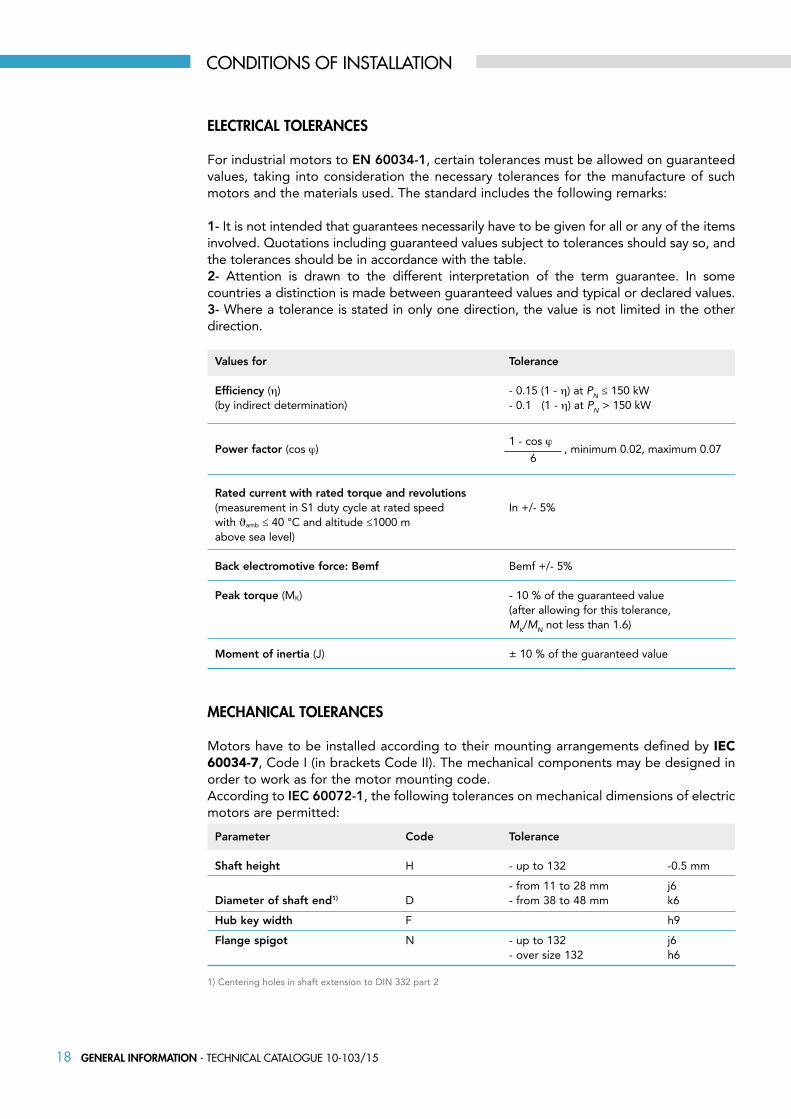
MEcHANIcAL TOLERANcES
Motors have to be installed according to their mounting arrangements defined by IEC 60034-7, Code I (in brackets Code II). The mechanical components may be designed in order to work as for the motor mounting code. According to IEC 60072-1, the following tolerances on mechanical dimensions of electric motors are permitted:
Parameter Code Tolerance
Shaft height H - up to 132 -0.5 mm
- from 11 to 28 mm j6Diameter of shaft end1) D - from 38 to 48 mm k6
Hub key width F h9
Flange spigot N - up to 132 j6 - over size 132 h6
1) Centering holes in shaft extension to DIN 332 part 2
ELEcTRIcAL TOLERANcES
For industrial motors to EN 60034-1, certain tolerances must be allowed on guaranteed values, taking into consideration the necessary tolerances for the manufacture of such motors and the materials used. The standard includes the following remarks:
1- It is not intended that guarantees necessarily have to be given for all or any of the items involved. Quotations including guaranteed values subject to tolerances should say so, and the tolerances should be in accordance with the table.2- Attention is drawn to the different interpretation of the term guarantee. In some countries a distinction is made between guaranteed values and typical or declared values.3- Where a tolerance is stated in only one direction, the value is not limited in the other direction.
Values for Tolerance
Efficiency (η) - 0.15 (1 - η) at PN ≤ 150 kW(by indirect determination) - 0.1 (1 - η) at PN > 150 kW
Power factor (cos ϕ) 1 - cos ϕ
, minimum 0.02, maximum 0.07
Rated current with rated torque and revolutions (measurement in S1 duty cycle at rated speed In +/- 5%with ϑamb ≤ 40 °C and altitude ≤1000 m above sea level)
Back electromotive force: Bemf Bemf +/- 5%
Peak torque (MK) - 10 % of the guaranteed value (after allowing for this tolerance, MK/MN not less than 1.6)
Moment of inertia (J) ± 10 % of the guaranteed value
6
CONDITIONS Of INSTALLATION

19GENERAL INFORMATION - Technical caTalogue 10-103/15
DERATING FOR AIR PRESSuRE
Below 1000 m altitude no derating is necessary. Above 1000 m the ambient temperature (TA) or max. rated output current (IN) must be derated in accordance with the following diagram.
See the below diagram for derating of output current versus altitude at TA = max. 40°C
THERMAL PROTEcTION AND DERATING
The HPS/HPI Motors are thermally protected in case limits are exceeded (140°C), another protection is provided throught the drive.
DERATING FOR AMbIENT TEMPERATuRE
The ambient temperature (TAMAX) is the maximum temperature allowed. If HPS/HPI Motor is operated at temperatures above 40 ºC, a derating of the continuous output current is necessary.
CONDITIONS Of INSTALLATION

20 GENERAL INFORMATION - Technical caTalogue 10-103/15
HPS ELEcTRIcAL cONNEcTION
The stand-alone HPS motor can NOT be installed directly on the mains. HPS motor needs always to be controlled by a drive. The 3 phases from the drive needs to be connected to U1, V1, W1 (Please see DWG 1).
HPS motors covered in this catalogue are all related to 400V data, and are designed for one supply voltage. It is not possible to make star/delta connections in the terminal box like on an AC motor. HPS motor is in general 3*400V but can also be delivered for 3*230V.
Rotation direction: there are two ways to change the rotating direction of the HPS motor. First of all by changing the sequences of 2 phases from the drive or by having the drive to change the rotating direction via the software (Please see DWG 2).
Warning: please be aware that when turning the shaft and without any connection to the drive, the HPS motor will work as a generator and deliver a voltage level (BEMF Voltage) according to the rotating speed.
DERATING FOR RuNNING AT LOw SPEED
When a centrifugal pump or a fan is controlled by a HPS/HPI Motor, it is not necessary to reduce the output at low speed because the load characteristic of the centrifugal pumps/fans, automatically ensures the necessary reduction.
HPS/HPI motors running constant load torque applications continuously at low speed must be derated (see diagram) or an independent fan must be used.
CONDITIONS Of INSTALLATION
DWG 1 DWG 2

21GENERAL INFORMATION - Technical caTalogue 10-103/15
GALVANIc ISOLATION (PELV)
Galvanic (ensured) isolation is obtained by fulfilling requirements concerning higher isolation and by providing the relevant clearpage/clearance distances. These requirements are described in the EN 50178 standard.
In HPI Series all control terminals are supplied from or in connection with extra low voltage (PELV).
The components that make up the electrical isolation, as described below, also comply with the requirements concerning higher isolation and the relevant test as described in EN 50178. The galvanic isolation can be shown in three locations (see drawing below), namely:
1. Power supply (SMPS) including signal isolation of VDCbus, indicating the intermediate voltage.
2. Gate drive that runs the IGBTs (opto couplers)
3. DCbus Voltage transducer (opto couplers)
4. Current transducers (Hall Effect-Based Current Sensor).
ELECTRICAL DESIGN
22 GENERAL INFORMATION - Technical caTalogue 10-103/15
EARTH LEAkAGE cuRRENT
Earth leakage current is primarily caused by the capacitance between motor phases and the motor frame. The RFI filter contributes additional leakage current, as the filter circuit is connected to earth through capacitors (Cy).
The size of the leakage current to the ground depends on the following factors, in order of priority:1 - Switching PWM frequency2 - Motor grounded on site or not
The leakage current is of importance to safety during handling/operation of the drive if (by mistake) the drive has not been earthed.
OVER VOLTAGE PROTEcTION
The voltage in the intermediate circuit is increased when the motor acts as a generator. This occurs in two cases:
1 - The load generates energy.2 - During deceleration (“ramp-down”) if the moment of inertia is high, the load is low and the ramp-down time is too short for the energy to be dissipated as a loss in the HPI frequency converter, the motor and the installation.
The drive turns off to protect the IGBT transistors and the intermediate circuit capacitors when a certain voltage level is reached on DCbus.
MAINS SuPPLy INTERFERENcE/HARMONIcS
A HPI integral drive takes up a non-sinusoidal current from mains. A non-sinusoidal current can be transformed by means of a Fourier analysis and split up into sine wave currents with different frequencies, i.e. different harmonic currents IN with 50 Hz as the basic frequency.
Some of the harmonic currents might disturb communication equipment connected to the same transformer or cause resonance in connection with power-factor correction batteries.To ensure low, harmonic currents, for the residential and commercial environments, an optional harmonic filter is necessary.
ELECTRICAL DESIGN

23GENERAL INFORMATION - Technical caTalogue 10-103/15
DEGREES OF PROTEcTION
Degrees of mechanical protection for machines are designated in accordance with IEC 60034-5 by the letters IP and two characteristic numerals.
IP Description
0 No special protection 1 Protection against solid foreign bodies larger than 50 mm (Example: inadvertent contact with the hand)
2 Protection against solid foreign bodies larger than 12 mm (Example: inadvertent contact with the fingers)
3 Protection against solid foreign bodies larger than 2.5 mm (Example: Wires, tools)
4 Protection against solid foreign bodies larger than 1 mm (Example: Wires, bands)
5 Protection against dust (harmful deposits of dust)
6 Complete protection against dust
IP Description
0 No special protection
1 Protection against vertically falling water drops (condensation)
2 Protection against dropping water when inclined by up to 15°
3 Protection against waterspray at up to 60° from vertical
4 Protection against water splashed from any direction
5 Protection against water projected by a nozzle from any direction
6 Protection against heavy seas or water projected in powerful jets
Second numeral:Protection against ingress of water
First numeral: Protection against contact and ingress of foreign bodies
ELECTRICAL DESIGN

24 GENERAL INFORMATION - Technical caTalogue 10-103/15
MECHANICAL DESIGN
It is essential to state the desired mounting arrangement when ordering, as the constructive design depends partly on the mounting arrangement.
MOuNTING ARRANGEMENTS
Mounting arrangements for rotating electrical machines are designated according to IEC 60034-7, Code I (in brackets Code II).
Foot mounting Flange mounting
IM B34 (IM 2101)Flange type C toDIN 42 948 at drive end
IM V6 (IM 1031)
IM V5 (IM 1011)
IM B8 (IM 1071)
IM B7 (IM 1061)
IM B6 (IM 1051)
IM B3 (IM 1001)
IM V19 (IM 3631)Flange type C toDIN 42 948 at drive end
IM V18 (IM 3611)Flange type C toDIN 42 948 at drive end
IM B14 (IM 3601)Flange type C toDIN 42 948 at drive end
IM B35 (IM 2001)Flange type A toDIN 42 948 at drive end
IM V3 (IM 3031)Flange type A toDIN 42 948 at drive end
IM V1 (IM 3011)Flange type A toDIN 42 948 at drive end
IM B5 (IM 3001)Flange type A toDIN 42 948 atdrive end
25GENERAL INFORMATION - Technical caTalogue 10-103/15
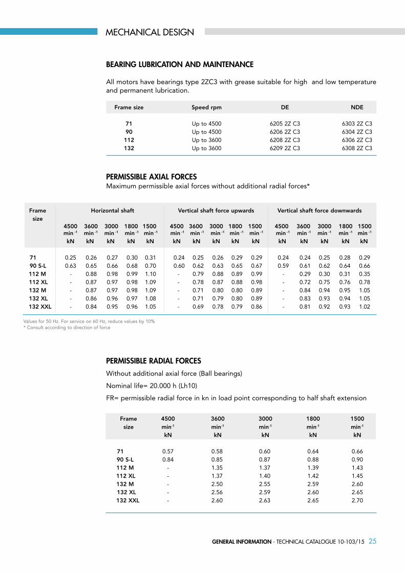
bEARING LubRIcATION AND MAINTENANcE
All motors have bearings type 2ZC3 with grease suitable for high and low temperature and permanent lubrication.
MECHANICAL DESIGN
Frame size Speed rpm DE NDE 71 Up to 4500 6205 2Z C3 6303 2Z C3 90 Up to 4500 6206 2Z C3 6304 2Z C3 112 Up to 3600 6208 2Z C3 6306 2Z C3 132 Up to 3600 6209 2Z C3 6308 2Z C3
PERMISSIbLE AXIAL FORcES Maximum permissible axial forces without additional radial forces*
Frame Horizontal shaft Vertical shaft force upwards Vertical shaft force downwards size
Frame 4500 3600 3000 1800 1500 size min-1 min-1 min-1 min-1 min-1
kN kN kN kN kN 71 0.57 0.58 0.60 0.64 0.66 90 S-L 0.84 0.85 0.87 0.88 0.90 112 M - 1.35 1.37 1.39 1.43 112 XL - 1.37 1.40 1.42 1.45 132 M - 2.50 2.55 2.59 2.60 132 XL - 2.56 2.59 2.60 2.65 132 XXL - 2.60 2.63 2.65 2.70
PERMISSIbLE RADIAL FORcES
Without additional axial force (Ball bearings)
Nominal life= 20.000 h (Lh10)
FR= permissible radial force in kn in load point corresponding to half shaft extension
4500 3600 3000 1800 1500 4500 3600 3000 1800 1500 4500 3600 3000 1800 1500 min -1 min -1 min -1 min -1 min -1 min -1 min -1 min -1 min -1 min -1 min -1 min -1 min -1 min -1 min -1
kN kN kN kN kN kN kN kN kN kN kN kN kN kN kN 71 0.25 0.26 0.27 0.30 0.31 0.24 0.25 0.26 0.29 0.29 0.24 0.24 0.25 0.28 0.29 90 S-L 0.63 0.65 0.66 0.68 0.70 0.60 0.62 0.63 0.65 0.67 0.59 0.61 0.62 0.64 0.66 112 M - 0.88 0.98 0.99 1.10 - 0.79 0.88 0.89 0.99 - 0.29 0.30 0.31 0.35 112 XL - 0.87 0.97 0.98 1.09 - 0.78 0.87 0.88 0.98 - 0.72 0.75 0.76 0.78 132 M - 0.87 0.97 0.98 1.09 - 0.71 0.80 0.80 0.89 - 0.84 0.94 0.95 1.05 132 XL - 0.86 0.96 0.97 1.08 - 0.71 0.79 0.80 0.89 - 0.83 0.93 0.94 1.05 132 XXL - 0.84 0.95 0.96 1.05 - 0.69 0.78 0.79 0.86 - 0.81 0.92 0.93 1.02 Values for 50 Hz. For service on 60 Hz, reduce values by 10%* Consult according to direction of force

26 GENERAL INFORMATION - Technical caTalogue 10-103/15
MECHANICAL DESIGN
Frame d x l1 b x h l2 l3 t size 71 19 x 40 6 x 6 30 6 21.5 90 24 x 50 8 x 7 40 6 27 112 28 x 60 8 x 7 50 6 31 132 38 x 80 10 x 8 70 5 41
Dimensions in mm.For larger shafts in special design the dimensions l2 and l3 are maintained.
POSITION AND DIMENSIONS OF KEy
cOOLING
TEFC execution as standard.Surface cooling, independent of the direction of rotation.
VIbRATION
The amplitude of vibration in electric motors is governed by EN 60034-14 Mechanical vibration of rotating electrical machines with shaft heights 56 and larger - methods of measurement and limits.Standard motors are designed to vibration grade A (normal). Vibration grade B is available at extra cost.
Rotors are at present dynamically balanced with half key fitted as per DIN ISO 8821. Other balancing only on request.The motors are identified as follows: “H” or “blank” means balanced with half key “F” means balanced with full key “N” means no key
l2
d
l1
l3
b
ht

NAMEPLATE EXAMPLE - HPS RANGE
NAMEPLATE EXAMPLE - HPI RANGE
MOTOR NAMEPLATE


29HPi iNTEGRAL DRiVE - Technical caTalogue 10-103/15
HPiinteGral DriVe

30 HPI INTEGRAL DRIVE - Technical caTalogue 10-103/15
MAIN SuPPLy (L1 L2 L3)Supply Frequency 48 - 62Hz
Supply Voltage 3 x 380/480V ± 10%
Max. Imbalance of supply voltage ± 2% of rated supply
Switching on supply voltage Once every 2 minutes
OuTPuT RATINGSOutput Current 100% Drive Rated Power continuously
Overload Capacity 150% for 60 secs
cONTROL SPEcIFIcATIONControl Method Sensorless AC Vector Control
Max PWM Frequency 12kHz
Frequency range up to 400 Hz
Resolution on output frequency 0.1%
Current/speed sampling time 83μs
DIGITAL INPuTSProgrammable digital inputs 4
Voltage level 0-24Vdc (user selectable npn or pnp)
PuLSE INPuTProgrammable pulse input 1
Voltage level 0:24Vdc
Max frequency 10kHz
ANALOG INPuTProgrammable analog voltage input 1
Voltage Level 0:10Vdc
Input Resistance Rin 10KΩ
Resolution 12bit
Programmable analog current inputs 1
Current Range 0:20mA
Input Resistance Rin 500Ω
Resolution 12bit
DRIVE SPECIfICATIONS

31HPI INTEGRAL DRIVE - Technical caTalogue 10-103/15
RELAy OuTPuTProgrammable relay output 1 (n.o. n.c. com)
Max terminal load 250Vac 2A 500VA
buS cOMuNIcATIONRS485 or Canbus For cascade mode
RS485 Serial comunication
Canbus Can-Open
EXTERNALSEnclosure IP55
Vibration test EC 60068-2-6
Max relatively umidity 95% (IEC 60068-2-3)
Operating ambient temperature 0:40°C
Storage ambient temperature - 25°C:60°C
Min. ambient temperature
at full operation 0°C
Altitude 0 - 3000m, derate 1% per 100m above 1000m
cOMPLIANcE wITH STANDARDSEN 61800-3:2004 Adjustable speed electrical power drive systems. EMC requirements
IEC 61800-5-1 Adjustable speed electrical drive systems - part 5-1: safety requirements - electrical, thermal and energy
EN 60204-1 Safety of machinery - electrical EMC equipment of machines - part 1: general rules
PROGRAMMINGKeypad yes
PC yes
DRIVE SPECIfICATIONS
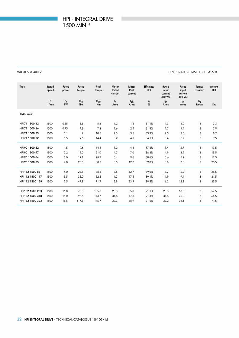
32 HPI INTEGRAL DRIVE - Technical caTalogue 10-103/15
TEMPERATURE RISE TO CLASS B
1500 min-1
HPI71 1500 12
HPI71 1500 16
HPI71 1500 23
HPI71 1500 32
HPI90 1500 32
HPI90 1500 47
HPI90 1500 64
HPI90 1500 85
HPI112 1500 85
HPI112 1500 117
HPI112 1500 159
HPI132 1500 233
HPI132 1500 318
HPI132 1500 393
1500 0.55 3.5 5.3 1.2 1.8 81.1% 1.3 1.0 3 7.3
1500 0.75 4.8 7.2 1.6 2.4 81.8% 1.7 1.4 3 7.9
1500 1.1 7 10.5 2.3 3.5 83.3% 2.5 2.0 3 8.7
1500 1.5 9.6 14.4 3.2 4.8 84.1% 3.4 2.7 3 9.5
1500 1.5 9.6 14.4 3.2 4.8 87.6% 3.4 2.7 3 13.5
1500 2.2 14.0 21.0 4.7 7.0 88.3% 4.9 3.9 3 15.5
1500 3.0 19.1 28.7 6.4 9.6 88.6% 6.6 5.2 3 17.5
1500 4.0 25.5 38.3 8.5 12.7 89.0% 8.8 7.0 3 20.5
1500 4.0 25.5 38.3 8.5 12.7 89.0% 8.7 6.9 3 28.5
1500 5.5 35.0 52.5 11.7 17.5 89.1% 11.9 9.4 3 31.5
1500 7.5 47.8 71.7 15.9 23.9 89.5% 16.2 12.8 3 35.5
1500 11.0 70.0 105.0 23.3 35.0 91.1% 23.3 18.5 3 57.5
1500 15.0 95.5 143.7 31.8 47.8 91.3% 31.8 25.2 3 64.5
1500 18.5 117.8 176.7 39.3 58.9 91.5% 39.2 31.1 3 71.5
Type Rated Rated Rated Peak Motor Motor Efficiency Rated Rated Torque Weight speed power torque torque Rated Peak HPI input input constant HPI current current current current 380 Vac 480 Vac n Pn Mn Mpk In Ipk η Iin Iin Kt 1/min kW Nm Nm Arms Arms % Arms Arms Nm/A Kg
HPI - INTEGRAL DRIVE1500 MIN -1
VALUES @ 400 V
33HPI INTEGRAL DRIVE - Technical caTalogue 10-103/15
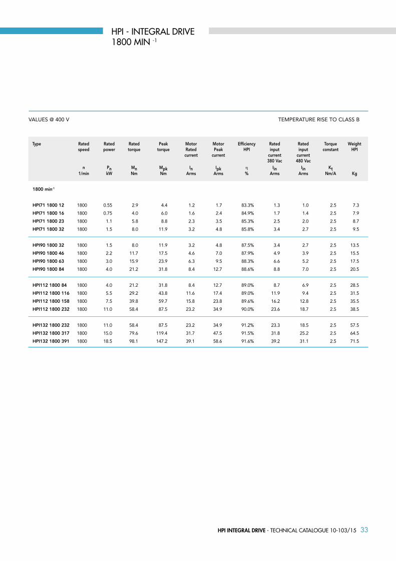
TEMPERATURE RISE TO CLASS B
1800 min-1
HPI71 1800 12
HPI71 1800 16
HPI71 1800 23
HPI71 1800 32
HPI90 1800 32
HPI90 1800 46
HPI90 1800 63
HPI90 1800 84
HPI112 1800 84
HPI112 1800 116
HPI112 1800 158
HPI112 1800 232
HPI132 1800 232
HPI132 1800 317
HPI132 1800 391
1800 0.55 2.9 4.4 1.2 1.7 83.3% 1.3 1.0 2.5 7.3
1800 0.75 4.0 6.0 1.6 2.4 84.9% 1.7 1.4 2.5 7.9
1800 1.1 5.8 8.8 2.3 3.5 85.3% 2.5 2.0 2.5 8.7
1800 1.5 8.0 11.9 3.2 4.8 85.8% 3.4 2.7 2.5 9.5
1800 1.5 8.0 11.9 3.2 4.8 87.5% 3.4 2.7 2.5 13.5
1800 2.2 11.7 17.5 4.6 7.0 87.9% 4.9 3.9 2.5 15.5
1800 3.0 15.9 23.9 6.3 9.5 88.3% 6.6 5.2 2.5 17.5
1800 4.0 21.2 31.8 8.4 12.7 88.6% 8.8 7.0 2.5 20.5
1800 4.0 21.2 31.8 8.4 12.7 89.0% 8.7 6.9 2.5 28.5
1800 5.5 29.2 43.8 11.6 17.4 89.0% 11.9 9.4 2.5 31.5
1800 7.5 39.8 59.7 15.8 23.8 89.6% 16.2 12.8 2.5 35.5
1800 11.0 58.4 87.5 23.2 34.9 90.0% 23.6 18.7 2.5 38.5
1800 11.0 58.4 87.5 23.2 34.9 91.2% 23.3 18.5 2.5 57.5
1800 15.0 79.6 119.4 31.7 47.5 91.5% 31.8 25.2 2.5 64.5
1800 18.5 98.1 147.2 39.1 58.6 91.6% 39.2 31.1 2.5 71.5
Type Rated Rated Rated Peak Motor Motor Efficiency Rated Rated Torque Weight speed power torque torque Rated Peak HPI input input constant HPI current current current current 380 Vac 480 Vac n Pn Mn Mpk In Ipk η Iin Iin Kt 1/min kW Nm Nm Arms Arms % Arms Arms Nm/A Kg
HPI - INTEGRAL DRIVE1800 MIN -1
VALUES @ 400 V
34 HPI INTEGRAL DRIVE - Technical caTalogue 10-103/15
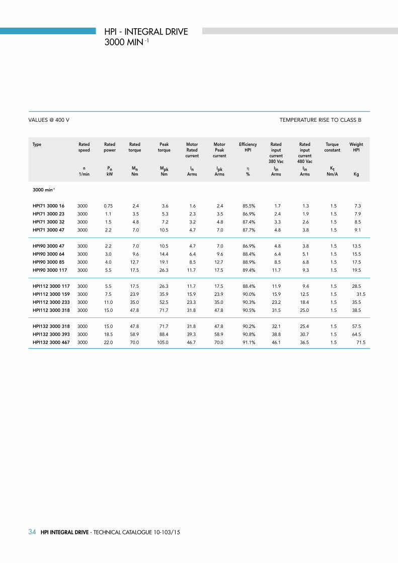
TEMPERATURE RISE TO CLASS B
3000 min-1
HPI71 3000 16
HPI71 3000 23
HPI71 3000 32
HPI71 3000 47
HPI90 3000 47
HPI90 3000 64
HPI90 3000 85
HPI90 3000 117
HPI112 3000 117
HPI112 3000 159
HPI112 3000 233
HPI112 3000 318
HPI132 3000 318
HPI132 3000 393
HPI132 3000 467
3000 0.75 2.4 3.6 1.6 2.4 85.5% 1.7 1.3 1.5 7.3
3000 1.1 3.5 5.3 2.3 3.5 86.9% 2.4 1.9 1.5 7.9
3000 1.5 4.8 7.2 3.2 4.8 87.4% 3.3 2.6 1.5 8.5
3000 2.2 7.0 10.5 4.7 7.0 87.7% 4.8 3.8 1.5 9.1
3000 2.2 7.0 10.5 4.7 7.0 86.9% 4.8 3.8 1.5 13.5
3000 3.0 9.6 14.4 6.4 9.6 88.4% 6.4 5.1 1.5 15.5
3000 4.0 12.7 19.1 8.5 12.7 88.9% 8.5 6.8 1.5 17.5
3000 5.5 17.5 26.3 11.7 17.5 89.4% 11.7 9.3 1.5 19.5
3000 5.5 17.5 26.3 11.7 17.5 88.4% 11.9 9.4 1.5 28.5
3000 7.5 23.9 35.9 15.9 23.9 90.0% 15.9 12.5 1.5 31.5
3000 11.0 35.0 52.5 23.3 35.0 90.3% 23.2 18.4 1.5 35.5
3000 15.0 47.8 71.7 31.8 47.8 90.5% 31.5 25.0 1.5 38.5
3000 15.0 47.8 71.7 31.8 47.8 90.2% 32.1 25.4 1.5 57.5
3000 18.5 58.9 88.4 39.3 58.9 90.8% 38.8 30.7 1.5 64.5
3000 22.0 70.0 105.0 46.7 70.0 91.1% 46.1 36.5 1.5 71.5
Type Rated Rated Rated Peak Motor Motor Efficiency Rated Rated Torque Weight speed power torque torque Rated Peak HPI input input constant HPI current current current current 380 Vac 480 Vac n Pn Mn Mpk In Ipk η Iin Iin Kt 1/min kW Nm Nm Arms Arms % Arms Arms Nm/A Kg
HPI - INTEGRAL DRIVE3000 MIN -1
VALUES @ 400 V

35HPI INTEGRAL DRIVE - Technical caTalogue 10-103/15
TEMPERATURE RISE TO CLASS B
3600 min-1
HPI71 3600 16
HPI71 3600 23
HPI71 3600 32
HPI71 3600 46
HPI90 3600 46
HPI90 3600 63
HPI90 3600 84
HPI90 3600 116
HPI112 3600 116
HPI112 3600 158
HPI112 3600 232
HPI112 3600 317
HPI132 3600 317
HPI132 3600 391
HPI132 3600 465
3600 0.75 2.0 3.0 1.6 2.4 86.4% 1.7 1.3 1.26 7.3
3600 1.1 2.9 4.4 2.3 3.5 87.2% 2.4 1.9 1.26 7.9
3600 1.5 4.0 6.0 3.2 4.8 97.9% 3.3 2.6 1.26 8.5
3600 2.2 5.8 8.8 4.6 7.0 88.1% 4.8 3.8 1.26 9.1
3600 2.2 5.8 8.8 4.6 7.0 88.1% 4.8 3.8 1.26 13.5
3600 3.0 8.0 11.9 6.3 9.5 88.7% 6.4 5.1 1.26 15.5
3600 4.0 10.6 15.9 8.4 12.7 89.2% 8.5 6.8 1.26 17.5
3600 5.5 14.6 21.9 11.6 17.4 89.7% 11.7 9.3 1.26 19.5
3600 5.5 14.6 21.9 11.6 17.4 89.5% 11.9 9.4 1.26 28.5
3600 7.5 19.9 29.8 15.8 23.8 90.1% 15.9 12.5 1.26 31.5
3600 11.0 29.2 43.8 23.2 34.9 90.5% 23.2 18.4 1.26 35.5
3600 15.0 39.8 59.7 31.7 47.5 90.7% 31.5 25.0 1.26 38.5
3600 15.0 39.8 59.7 31.7 47.5 90.5% 32.1 25.4 1.26 57.5
3600 18.5 49.1 73.6 39.1 58.6 90.9% 38.8 30.7 1.26 64.5
3600 22.0 58.4 87.5 46.5 69.7 91.1% 46.1 36.5 1.26 71.5
Type Rated Rated Rated Peak Motor Motor Efficiency Rated Rated Torque Weight speed power torque torque Rated Peak HPI input input constant HPI current current current current 380 Vac 480 Vac n Pn Mn Mpk In Ipk η Iin Iin Kt 1/min kW Nm Nm Arms Arms % Arms Arms Nm/A Kg
HPI - INTEGRAL DRIVE3600 MIN -1
VALUES @ 400 V

36 HPI INTEGRAL DRIVE - Technical caTalogue 10-103/15
TEMPERATURE RISE TO CLASS B
4500 min-1
HPI71 4500 23
HPI71 4500 32
HPI71 4500 47
HPI71 4500 64
HPI90 4500 64
HPI90 4500 85
HPI90 4500 117
HPI90 4500 159
4500 1.1 2.3 7.0 2.3 3.5 86.4% 2.4 1.9 1 7.3
4500 1.5 3.2 3.5 3.2 4.8 87.3% 3.3 2.6 1 7.9
4500 2.2 4.7 6.8 4.7 7.0 88.1% 4.8 3.8 1 8.7
4500 3.0 6.4 7.1 6.4 9.6 88.2% 6.5 5.1 1 9.5
4500 3.0 6.4 9.6 6.4 9.6 88.2% 6.4 5.1 1 13.5
4500 4.0 8.5 9.6 8.5 12.7 88.7% 8.5 6.8 1 15.5
4500 5.5 11.7 12.7 11.7 17.5 89.4% 11.7 9.3 1 17.5
4500 7.5 15.9 17.5 15.9 23.9 89.8% 15.9 12.6 1 20.5
Type Rated Rated Rated Peak Motor Motor Efficiency Rated Rated Torque Weight speed power torque torque Rated Peak HPI input input constant HPI current current current current 380 Vac 480 Vac n Pn Mn Mpk In Ipk η Iin Iin Kt 1/min kW Nm Nm Arms Arms % Arms Arms Nm/A Kg
HPI - INTEGRAL DRIVE4500 MIN -1
VALUES @ 400 V
37HPI INTEGRAL DRIVE - Technical caTalogue 10-103/15
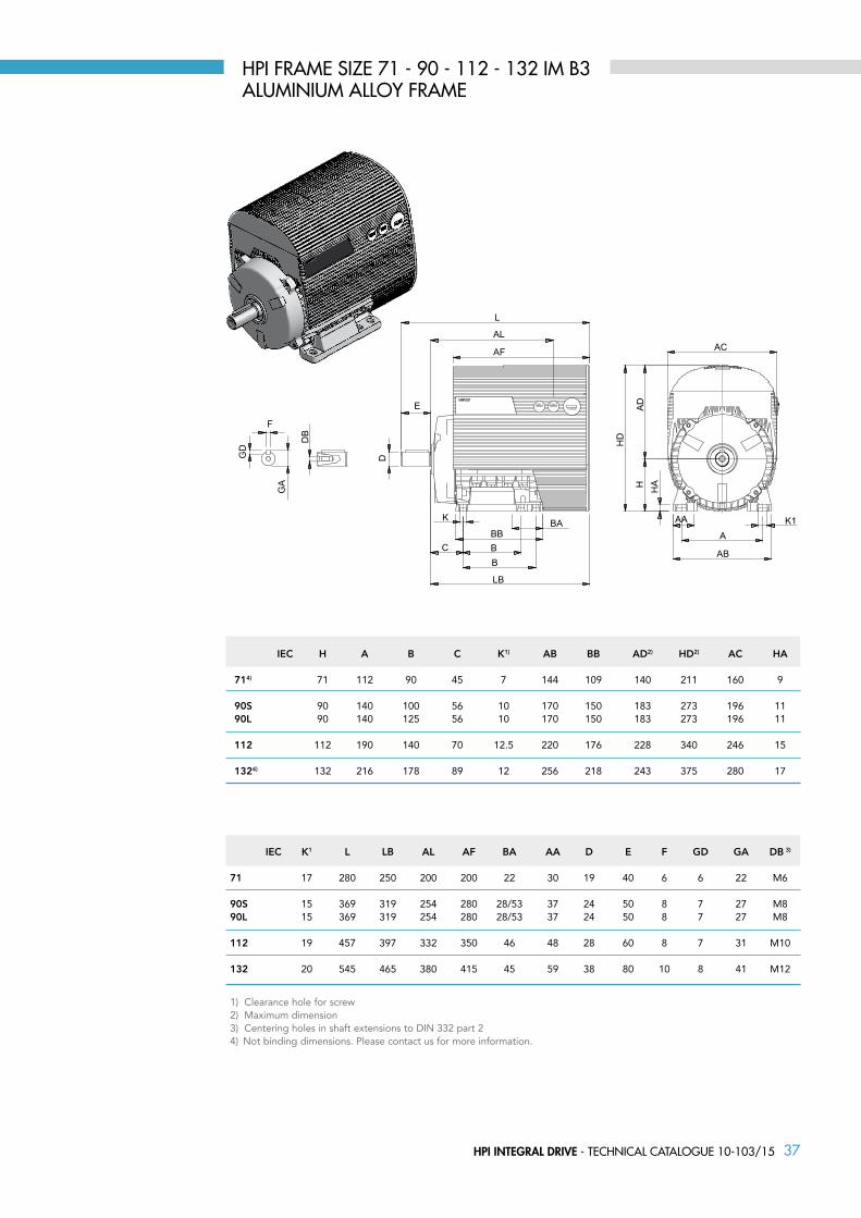
1) Clearance hole for screw2) Maximum dimension3) Centering holes in shaft extensions to DIN 332 part 24) Not binding dimensions. Please contact us for more information.
IEC H A B C K1) AB BB AD2) HD2) AC HA 714) 71 112 90 45 7 144 109 140 211 160 9
90S 90 140 100 56 10 170 150 183 273 196 11 90L 90 140 125 56 10 170 150 183 273 196 11
112 112 190 140 70 12.5 220 176 228 340 246 15 1324) 132 216 178 89 12 256 218 243 375 280 17
IEC K1 L LB AL AF BA AA D E F GD GA DB 3)
71 17 280 250 200 200 22 30 19 40 6 6 22 M6
90S 15 369 319 254 280 28/53 37 24 50 8 7 27 M890L 15 369 319 254 280 28/53 37 24 50 8 7 27 M8
112 19 457 397 332 350 46 48 28 60 8 7 31 M10
132 20 545 465 380 415 45 59 38 80 10 8 41 M12
HPI fRAME SIzE 71 - 90 - 112 - 132 IM B3ALUMINIUM ALLOY fRAME
38 HPI INTEGRAL DRIVE - Technical caTalogue 10-103/15
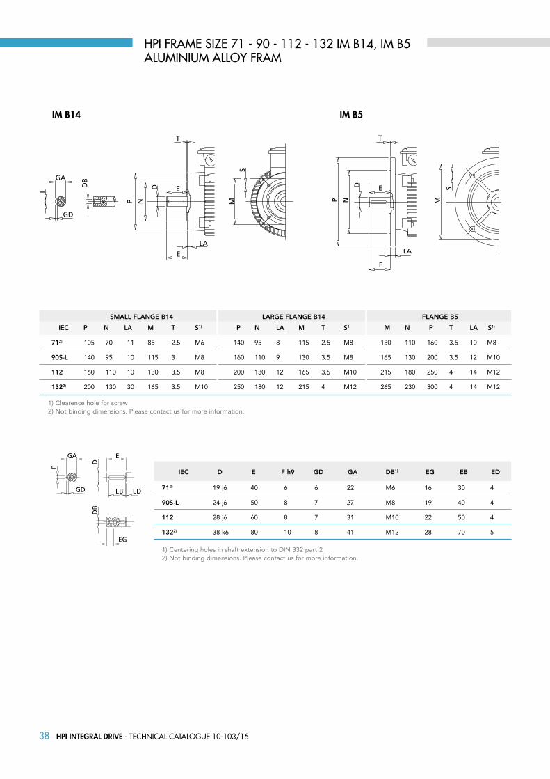
IM b5IM b14
IEC P N LA M T S1) P N LA M T S1) M N P T LA S1)
712) 105 70 11 85 2.5 M6 140 95 8 115 2.5 M8 130 110 160 3.5 10 M8
90S-L 140 95 10 115 3 M8 160 110 9 130 3.5 M8 165 130 200 3.5 12 M10
112 160 110 10 130 3.5 M8 200 130 12 165 3.5 M10 215 180 250 4 14 M12
1322) 200 130 30 165 3.5 M10 250 180 12 215 4 M12 265 230 300 4 14 M12
1) Clearence hole for screw 2) Not binding dimensions. Please contact us for more information.
SMALL FLANGE B14 LARGE FLANGE B14 FLANGE B5
IEC D E F h9 GD GA DB1) EG EB ED
712) 19 j6 40 6 6 22 M6 16 30 4
90S-L 24 j6 50 8 7 27 M8 19 40 4
112 28 j6 60 8 7 31 M10 22 50 4
1322) 38 k6 80 10 8 41 M12 28 70 5
1) Centering holes in shaft extension to DIN 332 part 22) Not binding dimensions. Please contact us for more information.
HPI fRAME SIzE 71 - 90 - 112 - 132 IM B14, IM B5ALUMINIUM ALLOY fRAM

39HPS-STAND ALONE MOTOR - Technical caTalogue 10-103/15
HPS - StanDalone motor

40 HPS-STAND ALONE MOTOR - Technical caTalogue 10-103/15
TEMPERATURE RISE TO CLASS B
1500 min-1
HPS71 1500 12
HPS71 1500 16
HPS71 1500 23
HPS71 1500 32
HPS90 1500 32
HPS90 1500 47
HPS90 1500 64
HPS90 1500 85
HPS112 1500 85
HPS112 1500 117
HPS112 1500 159
HPS112 1500 195
HPS132 1500 233
HPS132 1500 318
HPS132 1500 393
71 1500 0.55 3.5 10.5 1.73 3 272 1.2 86.0% 4.8
71 1500 0.75 4.8 14.4 1.73 3 272 1.6 87.0% 5.4
71 1500 1.1 7.0 21.0 1.73 3 272 2.3 87.8% 6.2
71 1500 1.5 9.6 28.8 1.73 3 272 3.2 88.5% 7.0
S-L 1500 1.5 9.6 28.7 1.73 3 272 3.2 91.0% 10.0
S-L 1500 2.2 14.0 42.0 1.73 3 272 4.7 91.5% 12.0
S-L 1500 3.0 19.1 57.3 1.73 3 272 6.4 92.0% 14.0
S-L 1500 4.0 25.5 76.4 1.73 3 272 8.5 92.3% 17.0
M 1500 4.0 25.5 76.4 1.73 3 272 8.5 92.4% 23.0
M 1500 5.5 35.0 105.1 1.73 3 272 11.7 92.5% 26.0
M 1500 7.5 47.8 143.3 1.73 3 272 15.9 93.1% 30.0
M 1500 9.2 58.6 175.8 1.73 3 272 19.5 93.0% 33.0
XL 1500 11.0 70.0 210.1 1.73 3 272 23.3 94.0% 51.0
XXL 1500 15.0 95.5 286.5 1.73 3 272 31.8 94.4% 58.0
XXL 1500 18.5 117.8 353.4 1.73 3 272 39.3 94.8% 65.0
Type Size Rated Rated Rated Peak Voltage Torque BEMF Rated Efficiency Weight speed power torque torque constant constant at rated current HPS speed n Pn Mn Mpk Ke Kt En In η 1/min kW Nm Nm Vs Nm/A Vrs Arms % Kg
HPS - STAND ALONE MOTOR1500 MIN -1
VALUES @ 400 V
IE4

41HPS-STAND ALONE MOTOR - Technical caTalogue 10-103/15
TEMPERATURE RISE TO CLASS B
1800 min-1
HPS71 1800 12
HPS71 1800 16
HPS71 1800 23
HPS71 1800 32
HPS90 1800 32
HPS90 1800 46
HPS90 1800 64
HPS90 1800 84
HPS112 1800 84
HPS112 1800 116
HPS112 1800 158
HPS112 1800 232
HPS132 1800 232
HPS132 1800 317
HPS132 1800 391
71 1800 0.55 2.9 8.8 1.45 2.5 272 1.2 87.7% 4.8
71 1800 0.75 4.0 11.9 1.45 2.5 272 1.6 88.4% 5.4
71 1800 1.1 5.8 17.5 1.45 2.5 272 2.3 88.9% 6.2
71 1800 1.5 8.0 23.9 1.45 2.5 272 3.2 89.4% 7
S-L 1800 1.5 8.0 23.9 1.45 2.5 272 3.2 91.2% 10
S-L 1800 2.2 11.7 35.0 1.45 2.5 272 4.6 91.6% 12
S-L 1800 3.0 15.9 47.7 1.45 2.5 272 6.3 92.1% 14
S-L 1800 4.0 21.2 63.7 1.45 2.5 272 8.4 92.4% 17
M 1800 4.0 21.2 63.7 1.45 2.5 272 8.4 92.5% 23
M 1800 5.5 29.2 87.5 1.45 2.5 272 11.6 92.6% 26
M 1800 7.5 39.8 119.4 1.45 2.5 272 15.8 93.3% 30
XL 1800 11.0 58.4 175.1 1.45 2.5 272 23.2 94.0% 33
M 1800 11.0 58.4 175.1 1.45 2.5 272 23.2 94.2% 51
XXL 1800 15.0 79.6 238.7 1.45 2.5 272 31.7 94.6% 58
XXL 1800 18.5 98.1 294.4 1.45 2.5 272 39.1 94.9% 65
Type Size Rated Rated Rated Peak Voltage Torque BEMF Rated Efficiency Weight speed power torque torque constant constant at rated current HPS speed n Pn Mn Mpk Ke Kt En In η 1/min kW Nm Nm Vs Nm/A Vrs Arms % Kg
HPS - STAND ALONE MOTOR1800 MIN -1
IE4VALUES @ 400 V
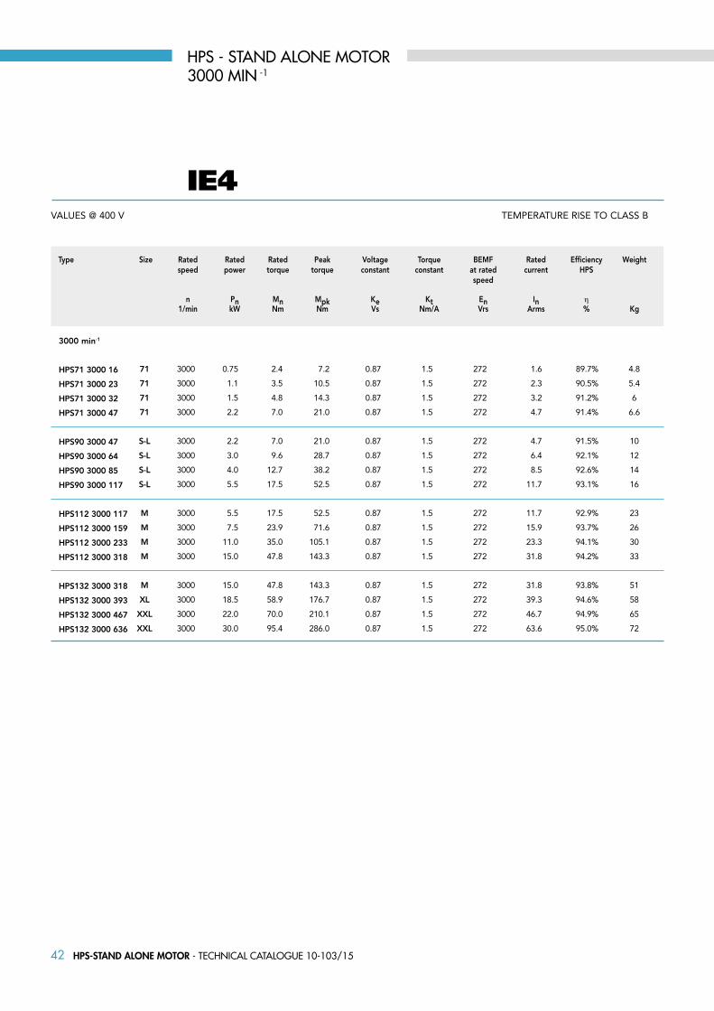
42 HPS-STAND ALONE MOTOR - Technical caTalogue 10-103/15
TEMPERATURE RISE TO CLASS B
3000 min-1
HPS71 3000 16
HPS71 3000 23
HPS71 3000 32
HPS71 3000 47
HPS90 3000 47
HPS90 3000 64
HPS90 3000 85
HPS90 3000 117
HPS112 3000 117
HPS112 3000 159
HPS112 3000 233
HPS112 3000 318
HPS132 3000 318
HPS132 3000 393
HPS132 3000 467
HPS132 3000 636
71 3000 0.75 2.4 7.2 0.87 1.5 272 1.6 89.7% 4.8
71 3000 1.1 3.5 10.5 0.87 1.5 272 2.3 90.5% 5.4
71 3000 1.5 4.8 14.3 0.87 1.5 272 3.2 91.2% 6
71 3000 2.2 7.0 21.0 0.87 1.5 272 4.7 91.4% 6.6
S-L 3000 2.2 7.0 21.0 0.87 1.5 272 4.7 91.5% 10
S-L 3000 3.0 9.6 28.7 0.87 1.5 272 6.4 92.1% 12
S-L 3000 4.0 12.7 38.2 0.87 1.5 272 8.5 92.6% 14
S-L 3000 5.5 17.5 52.5 0.87 1.5 272 11.7 93.1% 16
M 3000 5.5 17.5 52.5 0.87 1.5 272 11.7 92.9% 23
M 3000 7.5 23.9 71.6 0.87 1.5 272 15.9 93.7% 26
M 3000 11.0 35.0 105.1 0.87 1.5 272 23.3 94.1% 30
M 3000 15.0 47.8 143.3 0.87 1.5 272 31.8 94.2% 33
M 3000 15.0 47.8 143.3 0.87 1.5 272 31.8 93.8% 51
XL 3000 18.5 58.9 176.7 0.87 1.5 272 39.3 94.6% 58
XXL 3000 22.0 70.0 210.1 0.87 1.5 272 46.7 94.9% 65
XXL 3000 30.0 95.4 286.0 0.87 1.5 272 63.6 95.0% 72
Type Size Rated Rated Rated Peak Voltage Torque BEMF Rated Efficiency Weight speed power torque torque constant constant at rated current HPS speed n Pn Mn Mpk Ke Kt En In η 1/min kW Nm Nm Vs Nm/A Vrs Arms % Kg
HPS - STAND ALONE MOTOR3000 MIN -1
VALUES @ 400 V
IE4
43HPS-STAND ALONE MOTOR - Technical caTalogue 10-103/15
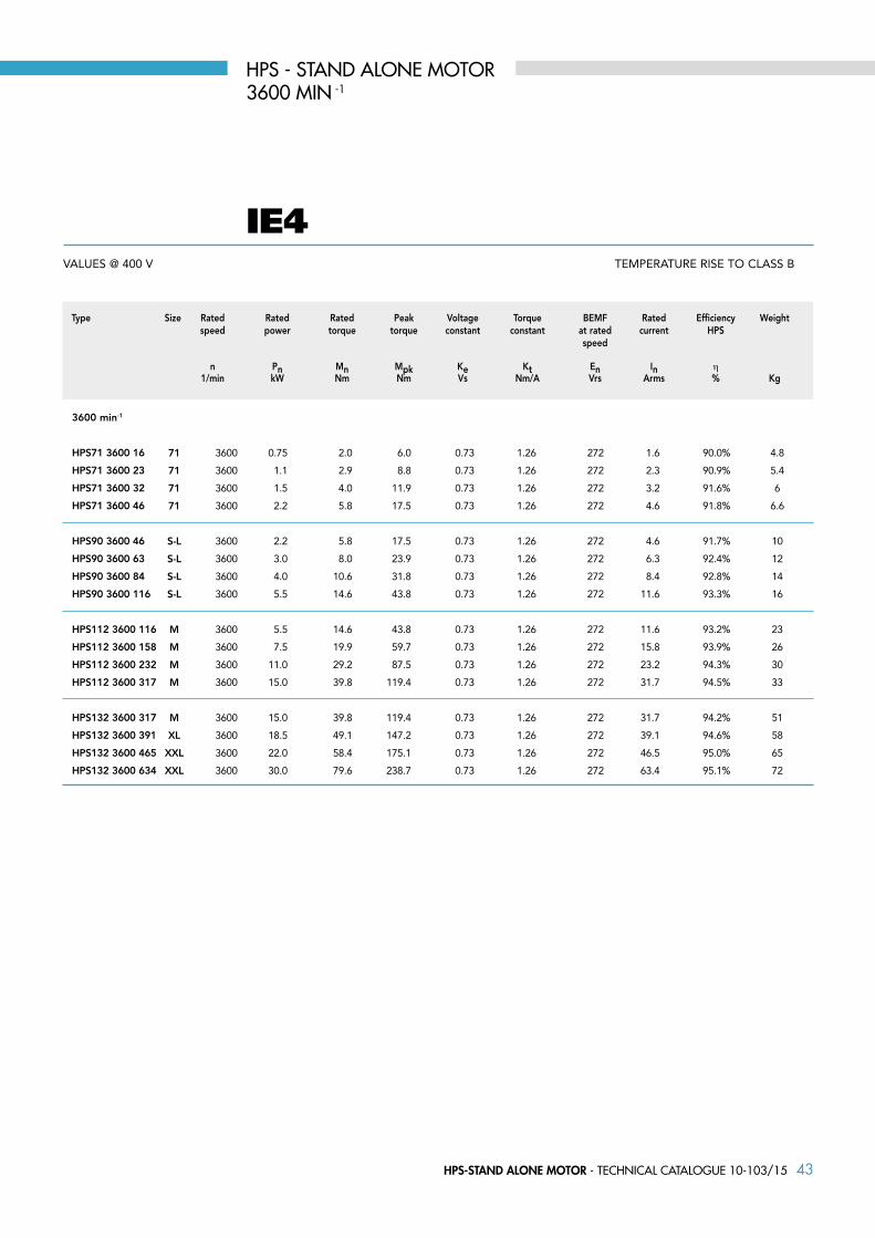
TEMPERATURE RISE TO CLASS B
3600 min-1
HPS71 3600 16
HPS71 3600 23
HPS71 3600 32
HPS71 3600 46
HPS90 3600 46
HPS90 3600 63
HPS90 3600 84
HPS90 3600 116
HPS112 3600 116
HPS112 3600 158
HPS112 3600 232
HPS112 3600 317
HPS132 3600 317
HPS132 3600 391
HPS132 3600 465
HPS132 3600 634
71 3600 0.75 2.0 6.0 0.73 1.26 272 1.6 90.0% 4.8
71 3600 1.1 2.9 8.8 0.73 1.26 272 2.3 90.9% 5.4
71 3600 1.5 4.0 11.9 0.73 1.26 272 3.2 91.6% 6
71 3600 2.2 5.8 17.5 0.73 1.26 272 4.6 91.8% 6.6
S-L 3600 2.2 5.8 17.5 0.73 1.26 272 4.6 91.7% 10
S-L 3600 3.0 8.0 23.9 0.73 1.26 272 6.3 92.4% 12
S-L 3600 4.0 10.6 31.8 0.73 1.26 272 8.4 92.8% 14
S-L 3600 5.5 14.6 43.8 0.73 1.26 272 11.6 93.3% 16
M 3600 5.5 14.6 43.8 0.73 1.26 272 11.6 93.2% 23
M 3600 7.5 19.9 59.7 0.73 1.26 272 15.8 93.9% 26
M 3600 11.0 29.2 87.5 0.73 1.26 272 23.2 94.3% 30
M 3600 15.0 39.8 119.4 0.73 1.26 272 31.7 94.5% 33
M 3600 15.0 39.8 119.4 0.73 1.26 272 31.7 94.2% 51
XL 3600 18.5 49.1 147.2 0.73 1.26 272 39.1 94.6% 58
XXL 3600 22.0 58.4 175.1 0.73 1.26 272 46.5 95.0% 65
XXL 3600 30.0 79.6 238.7 0.73 1.26 272 63.4 95.1% 72
Type Size Rated Rated Rated Peak Voltage Torque BEMF Rated Efficiency Weight speed power torque torque constant constant at rated current HPS speed n Pn Mn Mpk Ke Kt En In η 1/min kW Nm Nm Vs Nm/A Vrs Arms % Kg
HPS - STAND ALONE MOTOR3600 MIN -1
IE4VALUES @ 400 V
44 HPS-STAND ALONE MOTOR - Technical caTalogue 10-103/15
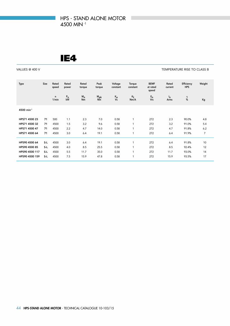
TEMPERATURE RISE TO CLASS B
4500 min-1
HPS71 4500 23
HPS71 4500 32
HPS71 4500 47
HPS71 4500 64
HPS90 4500 64
HPS90 4500 85
HPS90 4500 117
HPS90 4500 159
71 500 1.1 2.3 7.0 0.58 1 272 2.3 90.0% 4.8
71 4500 1.5 3.2 9.6 0.58 1 272 3.2 91.0% 5.4
71 4500 2.2 4.7 14.0 0.58 1 272 4.7 91.8% 6.2
71 4500 3.0 6.4 19.1 0.58 1 272 6.4 91.9% 7
S-L 4500 3.0 6.4 19.1 0.58 1 272 6.4 91.8% 10
S-L 4500 4.0 8.5 25.5 0.58 1 272 8.5 92.4% 12
S-L 4500 5.5 11.7 35.0 0.58 1 272 11.7 93.0% 14
S-L 4500 7.5 15.9 47.8 0.58 1 272 15.9 93.5% 17
Type Size Rated Rated Rated Peak Voltage Torque BEMF Rated Efficiency Weight speed power torque torque constant constant at rated current HPS speed n Pn Mn Mpk Ke Kt En In η 1/min kW Nm Nm Vs Nm/A Vrs Arms % Kg
HPS - STAND ALONE MOTOR4500 MIN -1
VALUES @ 400 V
IE4

45HPS-STAND ALONE MOTOR - Technical caTalogue 10-103/15
1) Clearance hole for screw2) Maximum dimension3) Centering holes in shaft extensions to DIN 332 part 2
IEC H A B C K1) AB BB AD2) HD2) AC HC HA
71 71 112 90 45 8 135 108 114 185 142 142 9
90S 90 140 100 56 10 170 150 148 238 177 181 1190L 90 140 125 56 10 170 150 148 238 177 181 11
112M 112 190 140 70 12.5 220 176 171 283 225 226 15112XL 112 190 140 70 12.5 220 176 171 283 225 226 15
IEC K1 L LB AL AF BA AA D E F GD GA DB 3)
71 17 245 215 75 93 22 30 19 40 6 6 22 M6
90S 15 317 267 85 110 28/53 37 24 50 8 7 27 M890L 15 317 267 85 110 28/53 37 24 50 8 7 27 M8
112M 19 388 328 92 110 46 48 28 60 8 7 31 M10112XL 19 410 350 92 110 46 48 28 60 8 7 31 M10
HPS fRAME SIzE 71 - 90 - 112 IM B3ALUMINIUM ALLOY fRAME
ONLy FOR SIZE 90L

46 HPS-STAND ALONE MOTOR - Technical caTalogue 10-103/15
??DISEGNO DOPPIO FORO DA INSERIRE
1) Clearance hole for screw2) Maximum dimension3) Centering holes in shaft extensions to DIN 332 part 2
IEC H A B C K1) AB BB AD2) HD2) AC HC HA
132M 132 216 178 89 12 256 218 195 327 248 261 17132XL 132 216 178 89 12 256 218 195 327 248 261 17132XXL 132 216 178 89 12 256 218 195 327 248 261 17
IEC K1 L LB AL AF BA AA D E F GD GA DB 3)
132M 20 485 405 122 133 45 59 38 80 10 8 41 M12132XL 20 505 425 122 133 45 59 38 80 10 8 41 M12132XXL 20 556 476 122 133 45 59 38 80 10 8 41 M12
HPS fRAME SIzE 132 IM B3ALUMINIUM ALLOY fRAME

47HPS-STAND ALONE MOTOR - Technical caTalogue 10-103/15
IM b5IM b14
IEC P N LA M T S1) P N LA M T S1) M N P T LA S1)
71 105 70 11 85 2.5 M6 140 95 8 115 2.5 M8 130 110 160 3.5 10 M8
90S-L 140 95 10 115 3 M8 160 110 9 130 3.5 M8 165 130 200 3.5 12 M10
112M-XL 160 110 10 130 3.5 M8 200 130 12 165 3.5 M10 215 180 250 4 14 M12
132M-XL-XXL 200 130 30 165 3.5 M10 250 180 12 215 4 M12 265 230 300 4 14 M12
1) Clearence hole for screw
SMALL FLANGE B14 LARGE FLANGE B14 FLANGE B5
IEC D E F h9 GD GA DB EG EB ED
71 19 j6 40 6 6 22 M6 16 30 4
90S-L 24 j6 50 8 7 27 M8 19 40 4 112M-XL 28 j6 60 8 7 31 M10 22 50 4
132M-XL-XXL 38 k6 80 10 8 41 M12 28 70 5
1) Centering holes in shaft extension to DIN 332 part 2
HPS fRAME SIzE 71 - 90 - 112 - 132 IM B14, IM B5ALUMINIUM ALLOY fRAME

All technical data, outputs, dimensions and weights stated in this catalogue are subject to change without prior notice.
The illustrations are not binding.
Printed in March 2015.

TECHNICAL CATALOGUE MKTG-10-103/15Branches & Partners
Lafert GmbH Olgastraße 34/1 D - 73728 Esslingen - Germany Phone +49 / (0) 711 540 3095 + 7 Fax +49 / (0) 711 540 3098 [email protected]
Lafert Electric Motors Ltd. Unit 17 Orion Way Crewe, Cheshire CW1 6NGUnited Kingdom Phone +44 / (0) 1270 270 022 Fax +44 / (0) 1270 270 [email protected]
Lafert Moteurs S.A.S. L’Isle d’Abeau Parc de Chesnes 75, rue de Malacombe F - 38070 St. Quentin-Fallavier France Phone +33 / 474 95 41 01 Fax +33 / 474 94 52 28 [email protected]
Lafert Motores Eléctricos, S.L.Polígono Pignatelli, Nave 27 E - 50410 Cuarte de Huerva (Zaragoza) - SpainPhone +34 / 976 503 822 Fax +34 / 976 504 199 [email protected]
Lafert N.A. (North America)5620 Kennedy Road - Mississauga Ontario L4Z 2A9 - Canada Phone +1 / 800/661 6413 - 905/629 1939Fax +1 / 905/629 2852 [email protected]
Lafert Electric Motors (Australia)Factory 3, 117-123 Abbott Road,Hallam - VIC 3803 - AustraliaPhone +61 / (0)3 95 46 75 15Fax +61 / (0)3 95 47 93 [email protected]
Lafert Singapore Pte Ltd48 Hillview Terrace #02-08 Hillview Building - Singapore 669269 Phone +65 / 67630400 - 67620400Fax +65 / [email protected]
Lafert (Suzhou) Co., Ltd.No.3 Industrial Plant Building Yue Xi Phase 3,Tian E Dang Lu 2011, 15104 Wu ZhongEconomic Development Zone, Suzhou, ChinaPhone +86 / 512 6687 0618Fax +86 / 512 6687 [email protected]
brAKE MOTOrs
sErVO MOTOrs & DrIVEs
LIFT MOTOrs
AC MOTOrs - IE3, IE2
HIGH PErFOrMANCE MOTOrs - IE4
MKTG
-10-10
3/15
www.lafert.com
TECHNICAL CATALOGUE 2015
Lafert S.p.A. Via J. F. Kennedy, 43I-30027 San Donà di Piave (Venice), ItalyTel. +39 / 0421 229 611 | Fax +39 / 0421 222 [email protected]
TE
CH
NIC
AL
CA
TALO
GU
E 2
01
5 -
Hig
h P
erf
orm
an
ce M
oto
rs
IE4
HIGH PERFORMANCE MOTORSINTEGRAL DRIVE (HPI RANGE)
STAND ALONE MOTOR (HPS RANGE)
HP SERIES