laminar flow ceiling diffuser steel • non-critical
TRANSCRIPT

SCHEDULE TYPE:PROJECT:ENGINEER:CONTRACTOR:
DATE B SERIES SUPERSEDES DRAWING NO.
6 - 7 - 16 9200 10 - 28 - 15 92LFD
LAMINAR FLOW CEILING DIFFUSERSTEEL • NON-CRITICAL APPLICATIONSLOW CAPACITY DESIGNMODEL: 92LFD
Nailor Industries Inc. reserves the right to change any information concerning product or pricing without notice.
Dimensions are in inches (mm).
CONSTRUCTION:1. Extruded aluminum frame and steel perforated face with3/32" (2.4) dia. holes on 60 degree 1/4" (6) staggeredcenters (13% free area). The face plate is removable forcleaning and is secured by 1/4 turn fasteners.
2. Corrosion resistant steel backpan, perforated inlet deflectorring and disk type damper. Damper adjustment throughremovable face plug.
3. Standard safety cables prevent accidental dropping ofremovable face.
4. Standard finish is AW Appliance White.OPTIONS:� EX External foil-back insulation (installed) – R-4.2.Finish:
� SP Special ________________ .
DESCRIPTION:The Model 92LFD Laminar Flow Diffuser is a lowcapacity/airflow range design and produces a non-aspirating,low velocity vertical air pattern. Recommended face velocityrange is 20 – 60 cfm/sq. ft.The steel construction 92LFD is designed to meet budgetaryneeds. Located above the work area, they provide a controlledlow velocity downward projection "piston" of conditioned supplyair.The only significant amount of room air entrainment occurs atthe outer boundary of the laminar flow mass, outside theconfines of the operating table.Applications include low invasive/minor surgical procedureoperating rooms and clean rooms such as research laboratories, animal labs, food processing, pharmaceutical labsand computer rooms where localized heavy cooling loadspresent a problem.
Imperial Modules (inches) 48 x 12 60 x 12 72 x 12 24 x 24 36 x 24 48 x 24 60 x 24 72 x 24L x WMetric Modules (mm) 1200 x 300 1500 x 300 1800 x 300 600 x 600 900 x 600 1200 x 600 1500 x 600 1800 x 600
6, 7, 6, 7, 6, 7, 6, 7, 6, 7, 8 7, 8, 8, 10, 8, 10,Duct (inches)
8 8 8 8, 10 10, 12 10, 12 12 12Size 152, 178, 152, 178, 152, 178, 152, 178, 152, 178, 203 178, 203, 203, 254, 203, 254,D (mm)
203 203 203 203, 254 254, 305 254, 305 305 305
D - 1/8" (3)
L - 1/4" (6)
CEILING MODULE LENGTH L
L - 3 1/2" (89)
6" (1
52)
3 1/4" (83)
W -
1/4"
(6)
PERFORATEDDEFLECTOR
REMOVABLEPLUG FOR
SCREWDRIVERACCESS
PERFORATED DIFFUSION DAMPER
13% FREE AREAPERFORATED FACE
STANDARDSAFETYCABLE
13% FREE AREAEQUALIZATION
BAFFLE
HANGERTABS (QTY. 4)
Ceiling Module Sizes L x W & Nominal Round Duct Sizes D
� TYPE S Surface MountDetail
� TYPE L* Lay-in T-Bar Detail
CEILING MODULE
CM - 1/4" (6)
CEILING OPENING= CM - 2" (51)
#8 PAN HEAD S. M. SCREWS
CEILING MODULE
CM - 1/4" (6)
*Compatible with all T-Bars up to 2" (51) wide.

SCHEDULE TYPE:PROJECT:ENGINEER:CONTRACTOR:
DATE B SERIES SUPERSEDES DRAWING NO.
10 - 28 - 15 9200 9 - 15 - 10 92LFD–AL
LAMINAR FLOW CEILING DIFFUSERALUMINUM • DUAL CHAMBER CRITICAL ENVIRONMENT APPLICATIONS LOW CAPACITY DESIGNMODEL: 92LFD-AL
Nailor Industries Inc. reserves the right to change any information concerning product or pricing without notice.
Dimensions are in inches (mm).
CONSTRUCTION:1. Extruded aluminum frame and aluminum perforated facewith 3/32" (2.4) dia. holes on 60 degree 1/4" (6) staggeredcenters (13% free area). The face plate is removable forcleaning and is secured by 1/4 turn fasteners.
2. Corrosion resistant steel backpan, perforated inlet deflectorring and disk type damper. Damper adjustment throughremovable face plug.
3. Standard safety cables prevent accidental dropping ofremovable face.
4. Standard finish is AW Appliance White.OPTIONS:� AB Aluminum backpan, deflector and damper.� EX External foil-back insulation (installed) – R-4.2.Finish:
� SP Special ________________ .
DESCRIPTION:The Model 92LFD-AL Laminar Flow Diffuser is a low capacity/airflowrange design and produces a non-aspirating, low velocity vertical airpattern. Recommended face velocity range is 20 – 60 cfm/sq. ft.Installed above the operating table in a hospital operating room, the'clean' conditioned air flows over the operating table so helping to protectand effectively isolate the patient from contaminated air. The "dual chamber" design and internal baffles provide improved airdistribution across the perforated diffuser face resulting in superiorperformance.The only significant amount of room air entrainment occurs at theouter boundary of the laminar flow mass, outside the confines of theoperating table.Other applications include clean rooms such as research laboratories, animal labs, food processing, pharmaceutical labs andcomputer rooms where localized heavy cooling loads present a problem.
D - 1/8" (3)
L - 1/4" (6)
CEILING MODULE LENGTH L
L - 3 1/2" (89)
6" (1
52)
3 1/4" (83)
W -
1/4"
(6)
PERFORATEDDEFLECTOR
REMOVABLEPLUG FOR
SCREWDRIVERACCESS
PERFORATED DIFFUSION DAMPER
13% FREE AREAPERFORATED FACE
13% FREE AREAEQUALIZATION
BAFFLE
STANDARDSAFETYCABLE
HANGERTABS (QTY. 4)
� TYPE S Surface MountDetail
� TYPE L* Lay-in T-Bar Detail
CEILING MODULE
CM - 1/4" (6)
CEILING OPENING= CM - 2" (51)
#8 PAN HEAD S. M. SCREWS
CEILING MODULE
CM - 1/4" (6)
*Compatible with all T-Bars up to 2" (51) wide.Ceiling Module Sizes L x W & Nominal Round Duct Sizes DImperial Modules (inches) 48 x 12 60 x 12 72 x 12 24 x 24 36 x 24 48 x 24 60 x 24 72 x 24L x WMetric Modules (mm) 1200 x 300 1500 x 300 1800 x 300 600 x 600 900 x 600 1200 x 600 1500 x 600 1800 x 600
6, 7, 6, 7, 6, 7, 6, 7, 6, 7, 8 7, 8, 8, 10, 8, 10,Duct (inches)
8 8 8 8, 10 10, 12 10, 12 12 12Size 152, 178, 152, 178, 152, 178, 152, 178, 152, 178, 203 178, 203, 203, 254, 203, 254,D (mm)
203 203 203 203, 254 254, 305 254, 305 305 305
L x W
Imperial Modules (inches) 48 x 12 60 x 12 24 x 24 36 x 24 48 x 24 60 x 24
Metric Modules (mm) 1200 x 300 1500 x 300 600 x 600 900 x 600 1200 x 600 1500 x 600
DuctSize
D
(inches) 6 6 6, 7, 8 6, 7, 8, 10 7, 8, 10, 12 10, 12
(mm) 152 152152, 178,
203152, 178,203, 254
178, 203,254, 305
254, 305
Ceiling Module Sizes L x W & Nominal Round Duct Sizes D
SCHEDULE TYPE PROJECT ENGINEER CONTRACTOR
DATE B SERIES SUPERSEDES DRAWING NO.
7 - 11 - 19 9200 6 - 27 - 19 92LFDF–AL
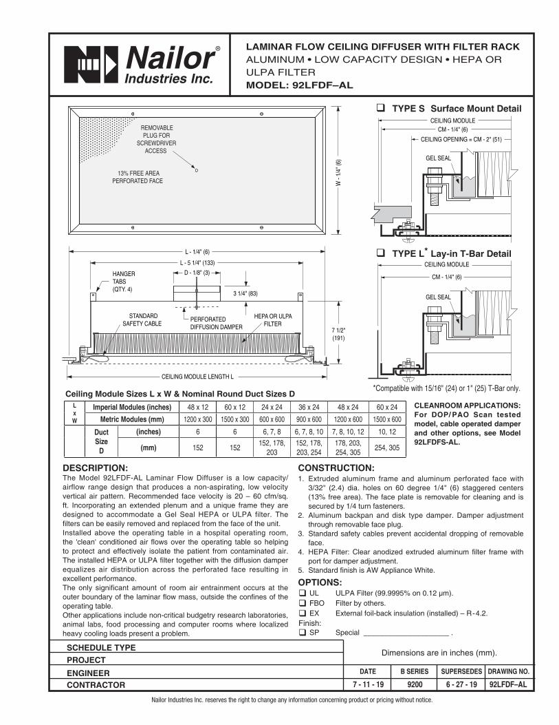
LAMINAR FLOW CEILING DIFFUSER WITH FILTER RACKALUMINUM • LOW CAPACITY DESIGN • HEPA OR ULPA FILTERMODEL: 92LFDF–AL
Nailor Industries Inc. reserves the right to change any information concerning product or pricing without notice.
Dimensions are in inches (mm).
q TYPE S Surface Mount Detail
q TYPE L* Lay-in T-Bar Detail
DESCRIPTION:The Model 92LFDF-AL Laminar Flow Diffuser is a low capacity/ airflow range design that produces a non-aspirating, low velocity vertical air pattern. Recommended face velocity is 20 – 60 cfm/sq. ft. Incorporating an extended plenum and a unique frame they are designed to accommodate a Gel Seal HEPA or ULPA filter. The filters can be easily removed and replaced from the face of the unit.Installed above the operating table in a hospital operating room, the 'clean' conditioned air flows over the operating table so helping to protect and effectively isolate the patient from contaminated air. The installed HEPA or ULPA filter together with the diffusion damper equalizes air distribution across the perforated face resulting in excellent performance.The only significant amount of room air entrainment occurs at the outer boundary of the laminar flow mass, outside the confines of the operating table.Other applications include non-critical budgetry research laboratories, animal labs, food processing and computer rooms where localized heavy cooling loads present a problem.
CONSTRUCTION:1. Extruded aluminum frame and aluminum perforated face with
3/32" (2.4) dia. holes on 60 degree 1/4" (6) staggered centers (13% free area). The face plate is removable for cleaning and is secured by 1/4 turn fasteners.
2. Aluminum backpan and disk type damper. Damper adjustment through removable face plug.
3. Standard safety cables prevent accidental dropping of removable face.
4. HEPA Filter: Clear anodized extruded aluminum filter frame with port for damper adjustment.
5. Standard finish is AW Appliance White.
OPTIONS:q UL ULPA Filter (99.9995% on 0.12 µm).q FBO Filter by others.q EX External foil-back insulation (installed) – R-4.2.Finish:q SP Special _____________________ .
D - 1/8" (3)
3 1/4" (83)
L - 1/4" (6)
CEILING MODULE LENGTH L
L - 5 1/4" (133)
7 1/2"(191)
STANDARDSAFETY CABLE
W -
1/4"
(6)
HEPA OR ULPAFILTER
PERFORATEDDIFFUSION DAMPER
HANGERTABS(QTY. 4)
REMOVABLEPLUG FOR
SCREWDRIVERACCESS
13% FREE AREAPERFORATED FACE
CEILING MODULECM - 1/4" (6)
CEILING OPENING = CM - 2" (51)
GEL SEAL
CEILING MODULE
CM - 1/4" (6)
GEL SEAL
*Compatible with 15/16" (24) or 1" (25) T-Bar only.
CLEANROOM APPLICATIONS:For DOP/ PAO Scan tested model, cable operated damper and other options, see Model 92LFDFS-AL.

SCHEDULE TYPE:PROJECT:ENGINEER:CONTRACTOR:
DATE B SERIES SUPERSEDES DRAWING NO.
7 - 17 - 17 9200 1 - 5 - 16 92LFDFS-AL
LAMINAR FLOW CEILING DIFFUSERALUMINUM HYBRID • CRITICAL ENVIRONMENT APPLICATIONS • LOW CAPACITY DESIGNHEPA OR ULPA FILTER • DOP SCAN TESTEDMODEL: 92LFDFS-AL
Nailor Industries Inc. reserves the right to change any information concerning product or pricing without notice.
Dimensions are in inches (mm).
CONSTRUCTION:1. 304 stainless steel frame and aluminum perforated face with 3/32" (2.4)
dia. holes on 60 degree 1/4" (6) staggered centers (13% free area). Theface plate is removable for cleaning and is secured by 1/4 turn fasteners.
2. 304 stainless steel fully welded plenum and face operated disc type damper.3. Standard safety cables prevent accidental dropping of removable face.4. HEPA Filter: Clear anodized extruded aluminum filter frame with port for
damper adjustment.5. Standard finish is AW Appliance White.OPTIONS AND ACCESSORIES:� UL ULPA Filter (99.9995% on 0.12 µm).� FBO Filter by others.� BDS Butterfly damper, Stainless Steel (face operated).� BDSR Butterfly damper, Stainless Steel with remote cable operator.� RDS Radial opposed blade damper, Stainless Steel (face operated).� RDSR Radial OBD, Stainless Steel with remote cable operator.� EX External foil-back insulation (installed) – R-4.2.� SPP Static pressure test /DOP port.� CPM DOP/PAO Challenge Port and Manifold.� LFI LED Loaded Filter Indicator.� STC Scan Testing Certificate.� SP Special Finish _____________________ .� PDB Perforated Diffusion Basket.
DESCRIPTION:The Model 92LFDFS-AL Laminar Flow Diffuser is a low capacity/airflow range design that produces a non-aspirating, low velocityvertical air pattern. Recommended face velocity is 20 – 60 cfm/sq. ft.Incorporating an extended plenum and a unique frame they aredesigned to accommodate a Gel Seal HEPA or ULPA filter. Thefilters can be easily removed and replaced from the face of the unit.Installed above the operating table in a hospital operating room,the 'clean' conditioned air flows over the operating table so helpingto protect and effectively isolate the patient from contaminated air.The installed HEPA or ULPA filter equalizes air distribution acrossthe perforated face resulting in excellent performance.The plenum is factory DOP scan tested for leaks in accordancewith Standard IEST-RP-CCO34.3.The only significant amount of room air entrainment occurs at theouter boundary of the laminar flow mass, outside the confines ofthe operating table.Other applications include clean rooms such as researchlaboratories, animal labs, food processing, pharmaceutical labsand computer rooms where localized heavy cooling loads presenta problem.
W –
1/4
" (6)
13% FREE AREAPERFORATED FACE
2 1/2" (64)
STANDARD SAFETY CABLE
D – 1/8" (3) L – 2 3/4" (70)
L – 1/4" (6)
CEILING MODULE LENGTH L
HANGERTABS
(QTY. 4)
OPTIONALDAMPERWITHREMOTE CABLEOPERATOR
9 1/
4" (2
35)HEPA FILTER
(STANDARD)
REMOVABLE PLUG FORSCREWDRIVER ACCESS
TO STANDARDDISC TYPE DAMPER
Ceiling Module Sizes L x W & Nominal Round Duct Sizes D
L x WImperial Modules (inches) 48 x 12 60 x 12 24 x 24 36 x 24 48 x 24 60 x 24Metric Modules (mm) 1200 x 300 1500 x 300 600 x 600 900 x 600 1200 x 600 1500 x 600
Duct Size D(inches) 6, 7, 8 6, 7, 8 6, 7, 8 6, 7, 8, 10 7, 8, 10, 12 10, 12
(mm) 152, 178,203
152, 178,203
152, 178,203
152, 178,203, 254
178, 203,254, 305 254, 305
GELSEAL
CEILING OPENING= CM – 1 1/4" (32)
CM – 1/4" (6)
KNIFEEDGE
GELSEAL
CEILING MODULE
CM - 1/4" (6)
* COMPATIBLE WITH T-BARS UP TO 1 1/2" (38) WIDE
KNIFEEDGE
GELSEAL
KNIFEEDGE
STATICPRESSUREPORT
PORTCAP
� TYPE S Surface Mount Detail
� TYPE L* Lay-in T-Bar Detail
Optional Static Pressure Port

SCHEDULE TYPE:PROJECT:ENGINEER:CONTRACTOR:
DATE B SERIES SUPERSEDES DRAWING NO.
8 - 1 - 17 9200 9 - 2 - 16 92LFDF-SS
LAMINAR FLOW CEILING DIFFUSERSTAINLESS STEEL • CRITICAL ENVIRONMENT APPLICATIONS • LOW CAPACITY DESIGNHEPA OR ULPA FILTER • DOP SCAN TESTEDMODEL: 92LFDF-SS
Nailor Industries Inc. reserves the right to change any information concerning product or pricing without notice.
Dimensions are in inches (mm).
CONSTRUCTION:1. 304 stainless steel frame and perforated face with 3/32" (2.4) dia. holes on 60degree 1/4" (6) staggered centers (13% free area). The face plate isremovable for cleaning and is secured by 1/4 turn fasteners.
2. 304 stainless steel fully welded plenum and face operated disc type damper.3. Standard safety cables prevent accidental dropping of removable face.4. HEPA Filter: Clear anodized extruded aluminum filter frame with port fordamper adjustment.
5. Standard finish is #4 Brushed Satin Polished.
DESCRIPTION:The Model 92LFDF-SS Laminar Flow Diffuser is a lowcapacity/airflow range design that produces a non-aspirating,low velocity vertical air pattern. Recommended face velocityis 20 – 60 cfm/sq. ft. Incorporating an extended plenum anda unique frame they are designed to accommodate a GelSeal HEPA or ULPA filter. The filters can be easily removedand replaced from the face of the unit.Installed above the operating table in a hospital operatingroom, the 'clean' conditioned air flows over the operatingtable so helping to protect and effectively isolate the patientfrom contaminated air. The installed HEPA or ULPA filterequalizes air distribution across the perforated face resultingin excellent performance.The plenum is factory DOP scan tested for leaks inaccordance with Standard IEST-RP-CCO34.3.The only significant amount of room air entrainment occursat the outer boundary of the laminar flow mass, outside theconfines of the operating table.Other applications include clean rooms such as researchlaboratories, animal labs, food processing, pharmaceuticallabs and computer rooms where localized heavy coolingloads present a problem.
W –
1/4
" (6)
13% FREE AREAPERFORATED FACE
2 1/2" (64)
STANDARD SAFETY CABLE
D – 1/8" (3) L – 2 3/4" (70)
L – 1/4" (6)
CEILING MODULE LENGTH L
HANGERTABS
(QTY. 4)
OPTIONALDAMPERWITHREMOTE CABLEOPERATOR
9 1/
4" (2
35)HEPA FILTER
(STANDARD)
REMOVABLE PLUG FORSCREWDRIVER ACCESS
TO STANDARDDISC TYPE DAMPER
GELSEAL
CEILING OPENING= CM – 1 1/4" (32)
CM – 1/4" (6)
KNIFEEDGE
GELSEAL
CEILING MODULE
CM - 1/4" (6)
* COMPATIBLE WITH T-BARS UP TO 1 1/2" (38) WIDE
KNIFEEDGE
GELSEAL
KNIFEEDGE
STATICPRESSUREPORT
PORTCAP
� TYPE S Surface Mount Detail
� TYPE L* Lay-in T-Bar Detail
Optional Static Pressure Port
Ceiling Module Sizes L x W & Nominal Round Duct Sizes D
L x WImperial Modules (inches) 24 x 12 48 x 12 60 x 12 24 x 24 36 x 24 48 x 24 60 x 24Metric Modules (mm) 600 x 300 1200 x 300 1500 x 300 600 x 600 900 x 600 1200 x 600 1500 x 600
Duct Size D(inches) 6, 7, 8 6, 7, 8 6, 7, 8 6, 7, 8 6, 7, 8, 10 7, 8, 10, 12 10, 12
(mm) 152, 178,203
152, 178,203
152, 178,203
152, 178,203
152, 178,203, 254
178, 203,254, 305 254, 305
OPTIONS AND ACCESSORIES:� 316 Stainless Steel construction.� UL ULPA Filter
(99.9995% on 0.12 µm).� FBO Filter by others.� BDS Butterfly damper, Stainless Steel (face operated).� BDSR Butterfly damper w/remote cable operator, Stainless Steel.� RDS Radial opposed blade damper, Stainless Steel (face operated).� RDSR Radial opposed blade damper, Stainless Steel w/remote cable operator.� EX External foil-back insulation (installed) – R-4.2.� SPP Static pressure test /DOP port.� CPM DOP/PAO Challenge Port and Manifold.� LFI LED Loaded Filter Indicator.� PDB Perforated Diffusion Basket.� STC Scan Testing Certificate.
Finish:� AW Appliance White. � BW British White.

SCHEDULE TYPE:PROJECT:ENGINEER:CONTRACTOR:
DATE B SERIES SUPERSEDES DRAWING NO.
10 - 29 - 15 9200 1 - 10 - 11 92LFDM–AL
LAMINAR FLOW CEILING DIFFUSERALUMINUM • DUAL CHAMBER CRITICAL ENVIRONMENT APPLICATIONSMEDIUM CAPACITY DESIGNMODEL: 92LFDM-AL
Nailor Industries Inc. reserves the right to change any information concerning product or pricing without notice.
Dimensions are in inches (mm).
CONSTRUCTION:1. Extruded aluminum frame, aluminum perforated face andequalization baffle with 3/32" (2.4) dia. holes on 60 degree 3/16"(5) staggered centers (23% free area). The face plate isremovable for cleaning and is secured by 1/4 turn fasteners.
2. Corrosion resistant steel backpan, perforated inlet deflector ringand disk type damper. Damper adjustment through removableface plug.
3. Standard safety cables prevent accidental dropping of removableface.
4. Standard finish is AW Appliance White.OPTIONS:� AB Aluminum backpan, equalization baffle, deflector and damper.� EX External foil-back insulation (installed) – R-4.2.Finish:
� SP Special ________________ .
DESCRIPTION:The Model 92LFDM-AL Laminar Flow Diffuser is a mediumcapacity/airflow range design and produces a non-aspirating,low velocity vertical air pattern. Recommended face velocityrange is 50 – 90 cfm/sq. ft.Located above the work area they provide a controlled lowvelocity downward projection "piston" of conditioned supply air.The "dual chamber" design and internal baffles provideimproved air distribution across the perforated diffuser faceresulting in superior performance.The only significant amount of room air entrainment occurs atthe outer boundary of the laminar flow mass.Applications include clean rooms such as research laboratories, animal labs, food processing, pharmaceuticallabs and computer rooms where localized heavy coolingloads present a problem.
Ceiling Module Sizes L x W & Nominal Round Duct Sizes D
D - 1/8" (3)
L - 1/4" (6)
CEILING MODULE LENGTH L
L - 3 1/2" (89)
6" (1
52)
STANDARDSAFETYCABLE 3 1/4" (83)
W -
1/4"
(6)
PERFORATEDDEFLECTOR
23% FREE AREAEQUALIZATION
BAFFLE
REMOVABLEPLUG FOR
SCREWDRIVERACCESS
PERFORATED DIFFUSION DAMPER
23% FREE AREAPERFORATED FACE
HANGERTABS (QTY. 4)
Imperial Modules (inches) 48 x 12 60 x 12 72 x 12 24 x 24 36 x 24 48 x 24 60 x 24 72 x 24L x WMetric Modules (mm) 1200 x 300 1500 x 300 1800 x 300 600 x 600 900 x 600 1200 x 600 1500 x 600 1800 x 600
Duct (inches) 8 10 10 8, 10, 12 10, 12, 14 10, 12, 14 12, 14, 16 14, 16, 18
Size 203, 254, 254, 305, 254, 305, 305, 356, 356, 406,D (mm) 203 254 254
305 356 356 406 457
� TYPE S Surface Mount Detail
� TYPE L* Lay-in T-Bar Detail
*Compatible with all T-Bars up to 2" (51) wide.
CEILING MODULE
CM - 1/4" (6)
CEILING OPENING= CM - 2" (51)
#8 PAN HEAD S. M. SCREWS
CEILING MODULE
CM - 1/4" (6)

L x W
Imperial Modules (inches) 24 x 24 36 x 24 48 x 24 60 x 24
Metric Modules (mm) 600 x 600 900 x 600 1200 x 600 1500 x 600
DuctSize
D
(inches) 8, 10, 12 10, 12, 14 10, 12, 14 12, 14, 16
(mm) 203, 254,305
254, 305,356
254, 305,356
305, 356,406
SCHEDULE TYPE: PROJECT: ENGINEER: CONTRACTOR:
DATE B SERIES SUPERSEDES DRAWING NO.
7 - 11 - 19 9200 11 - 2 - 15 92LFDMF-AL
LAMINAR FLOW CEILING DIFFUSER WITH FILTER RACKALUMINUM • MEDIUM CAPACITY DESIGN • HEPA OR ULPA FILTERMODEL: 92LFDMF-AL
Nailor Industries Inc. reserves the right to change any information concerning product or pricing without notice.
Dimensions are in inches (mm).
CONSTRUCTION:1. Extruded aluminum frame and aluminum perforated face with
3/32" (2.4) dia. holes on 60 degree 3/16" (5) staggered centers (23% free area). The face plate is removable for cleaning and is secured by 1/4 turn fasteners.
2. Aluminum backpan and perforated disc type damper. Damper adjustment through removable face plug.
3. Standard safety cables prevent accidental dropping of removable face.
4. HEPA Filter: Clear anodized extruded aluminum filter frame with port for damper adjustment.
5. Standard finish is AW Appliance White.OPTIONS:q UL ULPA Filter (99.9995% on 0.12 µm).q FBO Filter by others.q EX External foil-back insulation (installed) – R-4.2.Finish:q SP Special _____________________ .
DESCRIPTION:The Model 92LFDMF-AL Laminar Flow Diffuser is a medium capacity/airflow range design that produces a non-aspirating, low velocity vertical air pattern. Recommended face velocity is 50 – 90 cfm/sq. ft. Incorporating an extended plenum and a unique frame they are designed to accommodate a Gel Seal HEPA or ULPA filter. The filters can be easily removed and replaced from the face of the unit. Located above the work area, they provide a controlled low velocity downward projection "piston" of conditioned supply air. The installed HEPA or ULPA filter together with the diffusion damper equalizes air distribution across the perforated face resulting in excellent performance. The only significant amount of room entrainment occurs at the outer boundary of the laminar flow mass.Applications include non-critical research laboratories, animal labs, food processing and computer rooms where localized heavy cooling loads present a problem.
Ceiling Module Sizes L x W & Nominal Round Duct Sizes D
D - 1/8" (3)
3 1/4" (83)
L - 1/4" (6)
CEILING MODULE LENGTH L
L - 5 1/4" (133)
7 1/2"(191)
STANDARDSAFETY CABLE
W -
1/4"
(6)
HEPA OR ULPAFILTER
PERFORATEDDIFFUSION DAMPER
HANGERTABS(QTY. 4)
REMOVABLEPLUG FOR
SCREWDRIVERACCESS
23% FREE AREAPERFORATED FACE
CEILING MODULECM - 1/4" (6)
CEILING OPENING = CM - 2" (51)
GEL SEAL
q TYPE S Surface Mount Detail
q TYPE L* Lay-in T-Bar Detail
CEILING MODULE
CM - 1/4" (6)
GEL SEAL
*Compatible with 15/16" (24) or 1" (25) T-Bar only.
CLEANROOM APPLICATIONS:For DOP/PAO Scan tested model, cable operated damper and other options, see Model 92LFDMF-SS.

SCHEDULE TYPE:PROJECT:ENGINEER:CONTRACTOR:
DATE B SERIES SUPERSEDES DRAWING NO.
8 - 1 - 17 9200 9 - 2 - 16 92LFDMF-SS
LAMINAR FLOW CEILING DIFFUSERSTAINLESS STEEL • CRITICAL ENVIRONMENT APPLICATIONS • MEDIUM CAPACITY DESIGNDOP SCAN TESTED • HEPA OR ULPA FILTERMODEL: 92LFDMF-SS
Nailor Industries Inc. reserves the right to change any information concerning product or pricing without notice.
Dimensions are in inches (mm).
CONSTRUCTION:1. 304 stainless steel frame and perforated face with 3/32" (2.4) dia. holes on 60
degree 3/16" (5) staggered centers (23% free area). The face plate isremovable for cleaning and is secured by 1/4 turn fasteners.
2. 304 stainless steel fully welded plenum and perforated disc type damper.3. Standard safety cables prevent accidental dropping of removable face.4. HEPA Filter: Clear anodized extruded aluminum filter frame with port for
damper adjustment.5. Standard finish is #4 Brushed Satin Polished.
DESCRIPTION:The Model 92LFDMF-SS Laminar Flow Diffuser is amedium capacity/airflow range design that produces a non-aspirating, low velocity vertical air pattern. Recommendedface velocity is 50 – 90 cfm/sq. ft. Incorporating an extendedplenum and a unique frame they are designed toaccommodate a Gel Seal HEPA or ULPA filter. The filters canbe easily removed and replaced from the face of the unit.Located above the work area, they provide a controlled lowvelocity downward projection "piston" of conditioned supply air.The "dual chamber" design and internal baffles provideimproved air distribution across the perforated diffuser faceresulting in superior performance.The only significant amount of room entrainment occurs atthe outer boundary of the laminar flow mass.The plenum is factory DOP scan tested for leaks inaccordance with Standard IEST-RP-CCO34.3.Applications include clean rooms such as researchlaboratories, animal labs, food processing, pharmaceuticallabs and computer rooms where localized heavy coolingloads present a problem.
W –
1/4
" (6)
23% FREE AREAPERFORATED FACE
2 1/2" (64)
STANDARD SAFETY CABLE
D – 1/8" (3) L – 2 3/4" (70)
L – 1/4" (6)
CEILING MODULE LENGTH L
HANGERTABS
(QTY. 4)
OPTIONALDAMPERWITHREMOTE CABLEOPERATOR
9 1/
4" (2
35)HEPA FILTER
(STANDARD)
REMOVABLEPLUG FOR
SCREWDRIVERACCESS
GELSEAL
CEILING OPENING= CM – 1 1/4" (32)
CM – 1/4" (6)
KNIFEEDGE
GELSEAL
CEILING MODULE
CM - 1/4" (6)
* COMPATIBLE WITH T-BARS UP TO 1 1/2" (38) WIDE
KNIFEEDGE
GELSEAL
KNIFEEDGE
STATICPRESSUREPORT
PORTCAP
� TYPE S Surface Mount Detail
� TYPE L* Lay-in T-Bar Detail
Optional Static Pressure Port
OPTIONS AND ACCESSORIES:� 316 Stainless Steel construction.� UL ULPA Filter
(99.9995% on 0.12 µm).� FBO Filter by others.� BDS Butterfly damper, Stainless Steel (face operated).� BDSR Butterfly damper w/remote cable operator, Stainless Steel.� RDS Radial opposed blade damper, Stainless Steel (face operated).� RDSR Radial opposed blade damper, Stainless Steel w/remote cable operator.� EX External foil-back insulation (installed) – R-4.2.� SPP Static pressure test /DOP port.� CPM DOP/PAO Challenge Port and Manifold.� LFI LED Loaded Filter Indicator.� PDB Perforated Diffusion Basket.� STC Scan Testing Certificate.
Finish:� AW Appliance White. � BW British White.
Ceiling Module Sizes L x W & Nominal Round Duct Sizes D
L x WImperial Modules (inches) 48 x 12 60 x 12 24 x 24 36 x 24 48 x 24 60 x 24Metric Modules (mm) 1200 x 300 1500 x 300 600 x 600 900 x 600 1200 x 600 1500 x 600
Duct Size D(inches) 8 10 8, 10, 12 10, 12, 14 10, 12, 14 12, 14, 16
(mm) 203 254 203, 254,305
254, 305,356
254, 305,356
305, 356,406
SCHEDULE TYPE: PROJECT: ENGINEER: CONTRACTOR:
DATE B SERIES SUPERSEDES DRAWING NO.
5 - 10 - 21 9200 9 - 2 - 16 92LFDM-SS
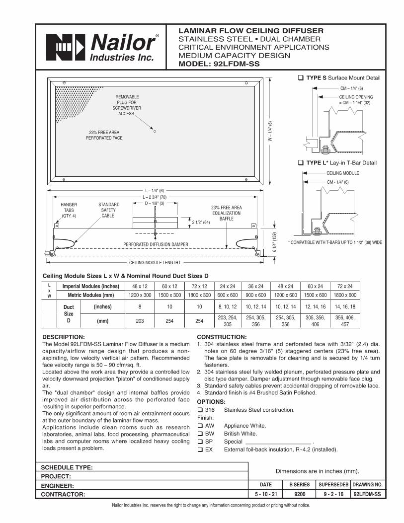
LAMINAR FLOW CEILING DIFFUSERSTAINLESS STEEL • DUAL CHAMBERCRITICAL ENVIRONMENT APPLICATIONSMEDIUM CAPACITY DESIGN MODEL: 92LFDM-SS
Nailor Industries Inc. reserves the right to change any information concerning product or pricing without notice.
Dimensions are in inches (mm).
CONSTRUCTION:1. 304 stainless steel frame and perforated face with 3/32" (2.4) dia.
holes on 60 degree 3/16" (5) staggered centers (23% free area). The face plate is removable for cleaning and is secured by 1/4 turn fasteners.
2. 304 stainless steel fully welded plenum, perforated pressure plate and disc type damper. Damper adjustment through removable face plug.
3. Standard safety cables prevent accidental dropping of removable face.4. Standard finish is #4 Brushed Satin Polished.
OPTIONS:q 316 Stainless Steel construction.Finish:q AW Appliance White. q BW British White. q SP Special _____________________ .q EX External foil-back insulation, R-4.2 (installed).
DESCRIPTION:The Model 92LFDM-SS Laminar Flow Diffuser is a medium capacity/airflow range design that produces a non-aspirating, low velocity vertical air pattern. Recommended face velocity range is 50 – 90 cfm/sq. ft.Located above the work area they provide a controlled low velocity downward projection "piston" of conditioned supply air. The "dual chamber" design and internal baffles provide improved air distribution across the perforated face resulting in superior performance.The only significant amount of room air entrainment occurs at the outer boundary of the laminar flow mass.Applications include clean rooms such as research laboratories, animal labs, food processing, pharmaceutical labs and computer rooms where localized heavy cooling loads present a problem.
W –
1/4
" (6)
23% FREE AREAPERFORATED FACE
2 1/2" (64)
D – 1/8" (3) L – 2 3/4" (70)
L – 1/4" (6)
CEILING MODULE LENGTH L
HANGERTABS
(QTY. 4)
6 1/
4" (1
59)
REMOVABLEPLUG FOR
SCREWDRIVERACCESS
PERFORATED DIFFUSION DAMPER
STANDARDSAFETYCABLE
23% FREE AREAEQUALIZATION
BAFFLE
Ceiling Module Sizes L x W & Nominal Round Duct Sizes D
CEILING OPENING= CM – 1 1/4" (32)
CM – 1/4" (6)
CEILING MODULE
CM - 1/4" (6)
* COMPATIBLE WITH T-BARS UP TO 1 1/2" (38) WIDE
q TYPE S Surface Mount Detail
q TYPE L* Lay-in T-Bar Detail
L x W
Imperial Modules (inches) 48 x 12 60 x 12 72 x 12 24 x 24 36 x 24 48 x 24 60 x 24 72 x 24
Metric Modules (mm) 1200 x 300 1500 x 300 1800 x 300 600 x 600 900 x 600 1200 x 600 1500 x 600 1800 x 600
DuctSize
D
(inches) 8 10 10 8, 10, 12 10, 12, 14 10, 12, 14 12, 14, 16 14, 16, 18
(mm) 203 254 254203, 254,
305254, 305,
356254, 305,
356305, 356,
406356, 406,
457

SCHEDULE TYPE: PROJECT: ENGINEER: CONTRACTOR:
DATE B SERIES SUPERSEDES DRAWING NO.
5 - 6 - 21 9200 9 - 2 - 16 92LFD-SS
LAMINAR FLOW CEILING DIFFUSERSTAINLESS STEEL • DUAL CHAMBERCRITICAL ENVIRONMENT APPLICATIONSLOW CAPACITY DESIGN MODEL: 92LFD-SS
Nailor Industries Inc. reserves the right to change any information concerning product or pricing without notice.
Dimensions are in inches (mm).
CONSTRUCTION:1. 304 stainless steel frame and perforated face with 3/32" (2.4) dia.
holes on 60 degree 1/4" (6) staggered centers (13% free area). The face plate is removable for cleaning and is secured by 1/4 turn fasteners.
2. 304 stainless steel fully welded plenum, perforated pressure plate and disc type damper. Damper adjustment through removable face plug.
3. Standard safety cables prevent accidental dropping of removable face.4. Standard finish is #4 Brushed Satin Polished.
OPTIONS:q 316 Stainless Steel construction.Finish:q AW Appliance White. q BW British White. q SP Special _____________________ .q EX External foil-back insulation, R-4.2 (installed).
DESCRIPTION:The Model 92LFD-SS Laminar Flow Diffuser is a low capacity/airflow range design that produces a non-aspirating, low velocity vertical air pattern. Recommended face velocity range is 20 – 60 cfm/sq. ft.Installed above the operating table in a hospital operating room, the 'clean' conditioned air flows over the operating table so helping to protect and effectively isolate the patient from contaminated air. The "dual chamber" design and internal baffles provide improved air distribution across the perforated face resulting in superior performance.The only significant amount of room air entrainment occurs at the outer boundary of the laminar flow mass, outside the confines of the operating table.Other applications include clean rooms such as research laboratories, animal labs, food processing, pharmaceutical labs and computer rooms where localized heavy cooling loads present a problem.
W –
1/4
" (6)
13% FREE AREAPERFORATED FACE
2 1/2" (64)
D – 1/8" (3) L – 2 3/4" (70)
L – 1/4" (6)
CEILING MODULE LENGTH L
HANGERTABS
(QTY. 4)
6 1/
4" (1
59)
REMOVABLEPLUG FOR
SCREWDRIVERACCESS
PERFORATED DIFFUSION DAMPER
STANDARDSAFETYCABLE
13% FREE AREAEQUALIZATION
BAFFLE
Ceiling Module Sizes L x W & Nominal Round Duct Sizes DL x W
Imperial Modules (inches) 24 x 12 48 x 12 60 x 12 72 x 12 24 x 24 36 x 24 48 x 24 60 x 24 72 x 24
Metric Modules (mm) 600 x 300 1200 x 300 1500 x 300 1800 x 300 600 x 600 900 x 600 1200 x 600 1500 x 600 1800 x 600
Duct Size D(inches) 6, 7, 8 6, 7, 8 6, 7, 8 6, 7, 8 6, 7, 8, 10 6, 7, 8, 10, 12 7, 8, 10, 12 8, 10, 12 8, 10, 12
(mm) 152, 178, 203
152, 178, 203
152, 178, 203
152, 178, 203
152, 178, 203, 254
152, 178, 203, 254, 305
178, 203, 254, 305
203, 254,305
203, 254,305
CEILING OPENING= CM – 1 1/4" (32)
CM – 1/4" (6)
CEILING MODULE
CM - 1/4" (6)
* COMPATIBLE WITH T-BARS UP TO 1 1/2" (38) WIDE
q TYPE S Surface Mount Detail
q TYPE L* Lay-in T-Bar Detail
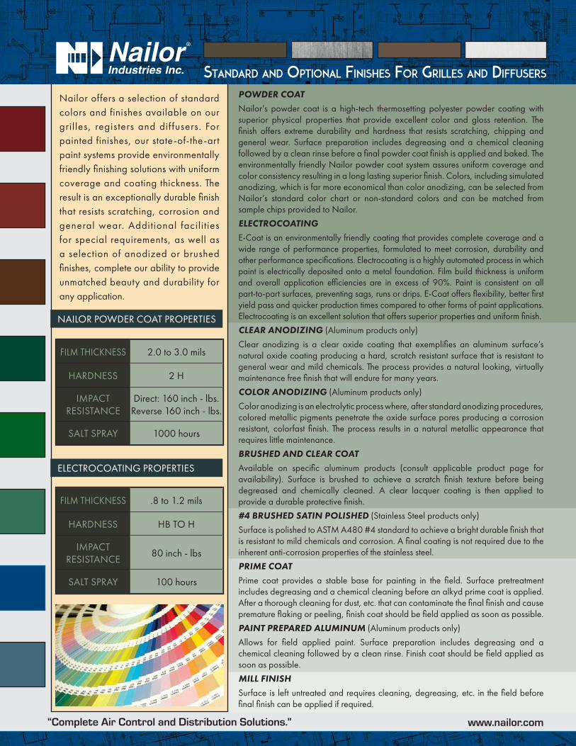
Standard and OptiOnal FiniSheS FOr GrilleS and diFFuSerS
Nailor offers a selection of standard colors and finishes available on our gril les, registers and dif fusers. For painted finishes, our state-of-the-art paint systems provide environmentally friendly finishing solutions with uniform coverage and coating thickness. The result is an exceptionally durable finish that resists scratching, corrosion and general wear. Additional facili t ies for special requirements, as well as a selection of anodized or brushed finishes, complete our ability to provide unmatched beauty and durability for any application.
POWDER COATNailor’s powder coat is a high-tech thermosetting polyester powder coating with superior physical properties that provide excellent color and gloss retention. The finish offers extreme durability and hardness that resists scratching, chipping and general wear. Surface preparation includes degreasing and a chemical cleaning followed by a clean rinse before a final powder coat finish is applied and baked. The environmentally friendly Nailor powder coat system assures uniform coverage and color consistency resulting in a long lasting superior finish. Colors, including simulated anodizing, which is far more economical than color anodizing, can be selected from Nailor’s standard color chart or non-standard colors and can be matched from sample chips provided to Nailor.
ELECTROCOATINGE-Coat is an environmentally friendly coating that provides complete coverage and a wide range of performance properties, formulated to meet corrosion, durability and other performance specifications. Electrocoating is a highly automated process in which paint is electrically deposited onto a metal foundation. Film build thickness is uniform and overall application efficiencies are in excess of 90%. Paint is consistent on all part-to-part surfaces, preventing sags, runs or drips. E-Coat offers flexibility, better first yield pass and quicker production times compared to other forms of paint applications. Electrocoating is an excellent solution that offers superior properties and uniform finish.
CLEAR ANODIZING (Aluminum products only)
Clear anodizing is a clear oxide coating that exemplifies an aluminum surface’s natural oxide coating producing a hard, scratch resistant surface that is resistant to general wear and mild chemicals. The process provides a natural looking, virtually maintenance free finish that will endure for many years.
COLOR ANODIZING (Aluminum products only)
Color anodizing is an electrolytic process where, after standard anodizing procedures, colored metallic pigments penetrate the oxide surface pores producing a corrosion resistant, colorfast finish. The process results in a natural metallic appearance that requires little maintenance.
BRUSHED AND CLEAR COATAvailable on specific aluminum products (consult applicable product page for availability). Surface is brushed to achieve a scratch finish texture before being degreased and chemically cleaned. A clear lacquer coating is then applied to provide a durable protective finish.
#4 BRUSHED SATIN POLISHED (Stainless Steel products only)
Surface is polished to ASTM A480 #4 standard to achieve a bright durable finish that is resistant to mild chemicals and corrosion. A final coating is not required due to the inherent anti-corrosion properties of the stainless steel.
PRIME COATPrime coat provides a stable base for painting in the field. Surface pretreatment includes degreasing and a chemical cleaning before an alkyd prime coat is applied. After a thorough cleaning for dust, etc. that can contaminate the final finish and cause premature flaking or peeling, finish coat should be field applied as soon as possible.
PAINT PREPARED ALUMINUM (Aluminum products only)
Allows for field applied paint. Surface preparation includes degreasing and a chemical cleaning followed by a clean rinse. Finish coat should be field applied as soon as possible.
MILL FINISHSurface is left untreated and requires cleaning, degreasing, etc. in the field before final finish can be applied if required.
NAILOR POWDER COAT PROPERTIES
ELECTROCOATING PROPERTIES
FILM THICKNESS 2.0 to 3.0 mils
HARDNESS 2 H
IMPACT RESISTANCE
Direct: 160 inch - lbs.Reverse 160 inch - lbs.
SALT SPRAY 1000 hours
FILM THICKNESS .8 to 1.2 mils
HARDNESS HB TO H
IMPACT RESISTANCE
80 inch - lbs
SALT SPRAY 100 hours
“Complete Air Control and Distribution Solutions.” www.nailor.com

Standard and OptiOnal FiniSheS FOr GrilleS and diFFuSerS
The following standard colors and finishes are available on applicable Nailor air distribution products. Consult individual product pages for availability
The pictured finishes have been represented as best as possible within printing limitations. However, actual finish may vary. Contact your Nailor representative for a color chip sample on the material specified for a more accurate representation.
DBK - Black (for registers ordered with factory mounted dampers) - BA - Perforated Diffusers (4300 series only) Appliance White (AW) face with black back pan and pattern controllers.
WGDSOF2015“Complete Air Control and Distribution Solutions.” www.nailor.com

Airflow, CFM 100 120 140 160 180 200 220 240 260 280 30048" x 12" Total Pressure .030 .043 .058 .076 .096 .119 .144 .172 .201 .233 .268
or NC — 17 19 22 25 27 29 31 34 35 371200 mm x 300 mm Throw .5-1-2 .5-1-3 1-1.5-4 1.5-2-4 1.5-2.5-5 2-3.5-5 2.5-4-6 3-4.5-7 3-4.5-7.5 4-5.5-8 4.5-6-9
60" x 12" Total Pressure .028 .040 .055 .072 .091 .112 .136 .161 .189 .220 .252or NC — 16 18 21 24 25 28 30 33 34 36
1500 mm x 300 mm Throw .5-1-2 1-1-3 1-1.5-4 1-2-4 1-2.5-4.5 2-3.5-5 2-4-5.5 3-4-6.5 3-5-7 4-5-8 4-6-8.572" x 12" Total Pressure .026 .037 .050 .066 .083 .103 .125 .148 .174 .202 .232
or NC — 16 18 21 23 26 27 30 32 33 351800 mm x 300 mm Throw .5-1-2 1-1-3 1-1.5-4 1-2-4 1-2.5-4.5 2-3.5-5 2-4.5-5 3-4-6.5 3-4.5-7 4-5-8 4-6-8.5
Module Size
PDAD92LFD-AL-SS
HOSPITAL/CLEANROOM DIFFUSERS
E
HO
SPIT
AL/
CLE
AN
RO
OM
DIF
FUSE
RS
8" (203 mm) dia. Inlet
10" (254 mm) dia. Inlet
12" (305 mm) dia. Inlet
6" (152 mm) dia. InletModule Size Airflow, CFM 80 100 120 140 160 180 200 220 240
24" x 24" Total Pressure, Pt 0.047 0.067 0.097 0.131 0.172 0.218 0.269 0.325 0.387
or Static Pressure, Ps 0.036 0.051 0.073 0.100 0.130 0.165 0.204 0.247 0.294
600 mm x 600 mm NC 22 26 30 35 38 41 43 45 47Throw, T .5-1-1 .5-1-2 .5-1-3 1-1.5-4 1.5-2-4 1.5-2.5-5 2-3.5-6 2.5-4-6 3-4.5-7
36" x 24" Total Pressure, Pt 0.036 0.056 0.081 0.111 0.144 0.183 0.226 0.273 0.325
or Static Pressure, Ps 0.026 0.040 0.058 0.079 0.103 0.130 0.161 0.195 0.232
900 mm x 600 mm NC 23 27 31 34 37 40 42 44 46Throw, T 0-1-1 0-1-1.5 0-1-2 0-1-3 1-2-3.5 1-2-4.5 2-3-5 2-3-5.5 2-3.5-6
4-6-10
Module Size Airflow, CFM 100 120 140 160 180 200 220 240 260 280 30024" x 24" Total Pressure .030 .043 .058 .076 .096 .119 .144 .172 .201 .233 .268
or NC — 17 19 22 25 27 29 31 34 35 37600 mm x 600 mm Throw .5-1-2 .5-1-3 1-1.5-4 1.5-2-4 1.5-2.5-5 2-3.5-6 2.5-4-6 3-4.5-7 3-4.5-7.5 4-5.5-8 4.5-6-9
36" x 24" Total Pressure .026 .037 .050 .066 .083 .103 .125 .148 .174 .202 .232or NC — 15 18 21 24 26 28 30 33 34 36
900 mm x 600 mm Throw 0-1-1.5 0-1-2 0-1-3 1-2-3.5 1-2-4.5 2-3-5 2-3-5.5 2-3.5-6 2.5-4.5-7 3-5-8 3-5-848" x 24" Total Pressure .023 .034 .046 .060 .075 .093 .113 .134 .158 .183 .210
or NC — — 17 20 23 25 27 30 32 33 351200 mm x 600 mm Throw 0-.5-1.5 .5-1-2 .5-1-2.5 1-1.5-3 1-2-4 1-2-5 1.5-2.5-5 2-3-6 2-4-6.5 2-4.5-7 3-5-7
Module Size Airflow, CFM 160 180 200 220 240 260 280 300 320 340 36048" x 24" Total Pressure .022 .028 .035 .042 .050 .059 .069 .079 .090 .113 .140
or NC — 15 18 19 22 25 27 29 31 33 351200 mm x 600 mm Throw 1-1-3 1-2-4 1-2-5 1.5-2.5-5 2-3-6 2-4-6.5 2-4.5-7 3-5-7 3-5-8 4-6-8.5 5-7-9
60" x 24" Total Pressure .021 .027 .033 .040 .048 .056 .065 .074 .084 .107 .132or NC — — 17 19 22 24 27 29 31 33 35
1500 mm x 600 mm Throw 1-1-3 1-2-4 1-2-5 1.5-2.5-5 2-3-6 2-4-6.5 2-4.5-7 3-5-7 3-5-8 4-6-8.5 5-7-972" x 24" Total Pressure .021 .027 .033 .036 .043 .050 .058 .066 .076 .096 .118
or NC — — 17 19 22 24 27 29 31 32 341800 mm x 600 mm Throw 1-1-3 1-1-4 1-2-4.5 1-2-5 1.5-2.5-6 2-3-6 2-4-7 2.5-4-7 3-4.5-7.5 3.5-5-8 4.5-6-9
Module Size Airflow, CFM 230 260 290 315 345 375 400 430 460 490 52048" x 24" Total Pressure .036 .046 .057 .068 .081 .096 .109 .126 .144 .163 .184
or NC 15 18 21 22 25 28 30 32 35 38 421200 mm x 600 mm Throw 1-2-6 1.5-3-6.5 2-4-7 3-5-8 4-5.5-8 4.5-6-8.5 5-7-9.5 5.5-7.5-10 6-8-11 6.5-8.5-11.5 7-9-12
60" x 24" Total Pressure .031 .040 .049 .058 .070 .083 .094 .108 .124 .141 .159or NC 15 18 21 22 25 28 30 32 35 38 42
1500 mm x 600 mm Throw 1-2-6 2-3-6 2-4-7 3-5-8 4-5.5-7.5 4.5-6-8.5 5-6.5-9 5.5-7.5-9.5 6-8-10.5 6-8.5-11 6.5-8.5-11.572" x 24" Total Pressure .028 .036 .045 .053 .063 .075 .085 .099 .113 .128 .144
or NC 14 17 20 21 24 27 29 31 34 37 411800 mm x 600 mm Throw 1-2-5 1.5-2.5-6 2-4-6.5 3-4.5-7 4-5-7 4-5.5-8 5-6-8.5 5-7-9 5.5-7.5-10 6-8-10.5 6-8-11
Imperial Units
Performance DataModels 92LFD-AL, 92LFD, 92LFD-SS
CFM - cubic feet per minuteFPM - feet per minute velocityTP - total pressure - inches w.g.T - throw in feetNC - Noise Criteria (values) based on
10 dB room absorption, re 10-12
watts. Damper fully open.
Performance Notes:1. Throws are the average vertical
distance in feet to terminal velocities of100, 75 and 50 fpm. Based upon acooling ΔT of 10°F. 9 ft. ceiling.
2. Data derived from tests conducted inaccordance with ANSI/ASHRAEStandard 70 – 1991.

PDAD92LFDF-AL-SS
LAMINAR FLOW DIFFUSERS WITH FILTERS
8" (203 mm) dia. InletModule Size Airflow, CFM 100 120 140 160 180 200 220 240 260 280 290
48" x 12" Total Pressure, Pt 0.17 0.24 0.33 0.43 0.55 0.68 0.82 0.98 1.14 1.33 1.42
or Static Pressure, Ps 0.16 0.24 0.32 0.42 0.53 0.66 0.79 0.94 1.11 1.28 1.38
1200 mm x 300 mm NC — 17 19 22 25 27 29 31 34 35 37Throw, T .5-1-2 .5-1-3 1-1.5-4 1.5-2-4 1.5-2.5-5 2-3.5-5 2.5-4-6 3-4.5-7 3-4.5-7.5 4-5.5-8 4.5-6-9
60" x 12" Total Pressure, Pt 0.11 0.16 0.22 0.28 0.36 0.44 0.54 0.64 0.75 0.87 0.93
or Static Pressure, Ps 0.11 0.15 0.21 0.27 0.34 0.42 0.51 0.61 0.71 0.83 0.89
1500 mm x 300 mm NC — 16 18 21 24 25 28 30 33 34 36Throw, T .5-1-2 1-1-3 1-1.5-4 1-2-4 1-2.5-4.5 2-3.5-5 2-4-5.5 3-4-6.5 3-5-7 4-5-8 4-6-8.5
10" (254 mm) dia. Inlet
12" (305 mm) dia. Inlet
Module Size Airflow, CFM 100 120 140 160 180 200 220 240 260 280 295
24" x 24" Total Pressure, Pt 0.17 0.24 0.32 0.42 0.54 0.66 0.80 0.95 1.12 1.30 1.44
or Static Pressure, Ps 0.16 0.23 0.31 0.41 0.52 0.64 0.77 0.92 1.08 1.25 1.39
600 mm x 600 mm NC — 17 19 22 25 27 29 31 34 35 37Throw, T .5-1-2 .5-1-3 1-1.5-4 1.5-2-4 1.5-2.5-5 2-3.5-6 2.5-4-6 3-4.5-7 3-4.5-7.5 4-5.5-8 4.5-6-9
36" x 24" Total Pressure, Pt 0.07 0.10 0.14 0.18 0.23 0.29 0.35 0.41 0.48 0.56 0.62
or Static Pressure, Ps 0.07 0.10 0.13 0.17 0.21 0.26 0.32 0.38 0.45 0.52 0.58
900 mm x 600 mm NC — 15 18 21 24 26 28 30 33 34 36Throw, T 0-1-1.5 0-1-2 0-1-3 1-2-3.5 1-2-4.5 2-3-5 2-3-5.5 2-3.5-6 2.5-4.5-7 3-5-8 3-5-8
48" x 24" Total Pressure, Pt 0.05 0.07 0.09 0.12 0.15 0.18 0.22 0.27 0.31 0.36 0.40
or Static Pressure, Ps 0.04 0.06 0.08 0.10 0.13 0.16 0.20 0.24 0.28 0.32 0.36
1200 mm x 600 mm NC — — 17 20 23 25 27 30 32 33 35Throw, T 0-.5-1.5 .5-1-2 .5-1-2.5 1-1.5-3 1-2-4 1-2-5 1.5-2.5-5 2-3-6 2-4-6.5 2-4.5-7 3-5-7
Module Size Airflow, CFM 160 180 200 220 240 260 280 300 320 340 360
36" x 24" Total Pressure, Pt 0.14 0.18 0.22 0.27 0.32 0.37 0.43 0.50 0.56 0.64 0.71
or Static Pressure, Ps 0.14 0.17 0.21 0.26 0.30 0.36 0.41 0.48 0.54 0.61 0.69
900 mm x 600 mm NC 15 18 20 21 23 26 28 30 32 34 36Throw, T 1-2-3.5 1-2-4.5 2-3-5 2-3-5.5 2-3.5-6 2.5-4-7 3-5-8 3-5-8 4-5.5-8.5 4-6-9 5-7-9.5
48" x 24" Total Pressure, Pt 0.08 0.10 0.13 0.15 0.18 0.21 0.25 0.28 0.32 0.37 0.41
or Static Pressure, Ps 0.08 0.10 0.12 0.14 0.17 0.20 0.23 0.27 0.30 0.34 0.38
1200 mm x 600 mm NC — 15 18 19 22 25 27 29 31 33 35Throw, T 1-1-3 1-2-4 1-2-5 1.5-2.5-5 2-3-6 2-4-6.5 2-4.5-7 3-5-7 3-5-8 4-6-8.5 5-7-9
60" x 24" Total Pressure, Pt 0.06 0.07 0.09 0.11 0.13 0.15 0.17 0.20 0.22 0.25 0.28
or Static Pressure, Ps 0.05 0.06 0.08 0.10 0.11 0.13 0.15 0.18 0.20 0.23 0.26
1500 mm x 600 mm NC — — 17 19 22 24 27 29 31 33 35Throw, T 1-1-3 1-2-4 1-2-5 1.5-2.5-5 2-3-6 2-4-6.5 2-4.5-7 3-5-7 3-5-8 4-6-8.5 5-7-9
Module Size Airflow, CFM 230 260 290 315 345 375 400 430 460 490 520
48" x 24" Total Pressure, Pt 0.16 0.20 0.25 0.29 0.35 0.42 0.48 0.55 0.63 0.71 0.80
or Static Pressure, Ps 0.15 0.19 0.24 0.28 0.34 0.40 0.46 0.53 0.61 0.69 0.78
1200 mm x 600 mm NC 15 18 20 22 23 25 26 28 30 32 33Throw, T 1-2-6 1.5-3-6.5 2-4-7 3-5-8 4-5.5-8 4.5-6-8.5 5-7-9.5 5.5-7.5-10 6-8-11 6.5-8.5-11.5 7-9-12
60" x 24" Total Pressure, Pt 0.10 0.13 0.16 0.19 0.23 0.27 0.31 0.36 0.41 0.47 0.53
or Static Pressure, Ps 0.10 0.12 0.16 0.18 0.22 0.26 0.30 0.34 0.39 0.44 0.50
1500 mm x 600 mm NC 15 18 20 22 23 25 26 28 30 32 33Throw, T 1-2-6 2-3-6 2-4-7 3-5-8 4-5.5-7.5 4.5-6-8.5 5-6.5-9 5.5-7.5-9.5 6-8-10.5 6-8.5-11 6.5-8.5-11.5
*
* E
HO
SPITA
L/CLEA
NRO
OM
DIFFU
SERS
6" (152 mm) dia. InletModule Size Airflow, CFM 80 100 120 140 160 180 200 220 240
24" x 24" Total Pressure, Pt 0.13 0.20 0.29 0.38 0.52 0.65 0.81 0.98 1.17
or Static Pressure, Ps 0.12 0.18 0.26 0.36 0.47 0.60 0.74 0.90 1.07
600 mm x 600 mm NC 22 26 30 35 38 41 43 45 47Throw, T .5-1-1 .5-1-2 .5-1-3 1-1.5-4 1.5-2-4 1.5-2.5-5 2-3.5-6 2.5-4-6 3-4.5-7
36" x 24" Total Pressure, Pt 0.09 0.11 0.16 0.21 0.27 0.34 0.43 0.52 0.61
or Static Pressure, Ps 0.08 0.09 0.13 0.18 0.23 0.29 0.36 0.44 0.52
900 mm x 600 mm NC 23 27 31 34 37 40 42 44 46Throw, T 0-1-1 0-1-1.5 0-1-2 0-1-3 1-2-3.5 1-2-4.5 2-3-5 2-3-5.5 2-3.5-6
Imperial Units
Performance DataModel 92LFDF-AL, 92LFDF-SSWith HEPA Filter • 99.99% Minimum Removal Efficiency on 0.30 Micrometer Particle Size
For Performance Notes, please see Air Distribution Products catalog page E57.
4-1-10
E57
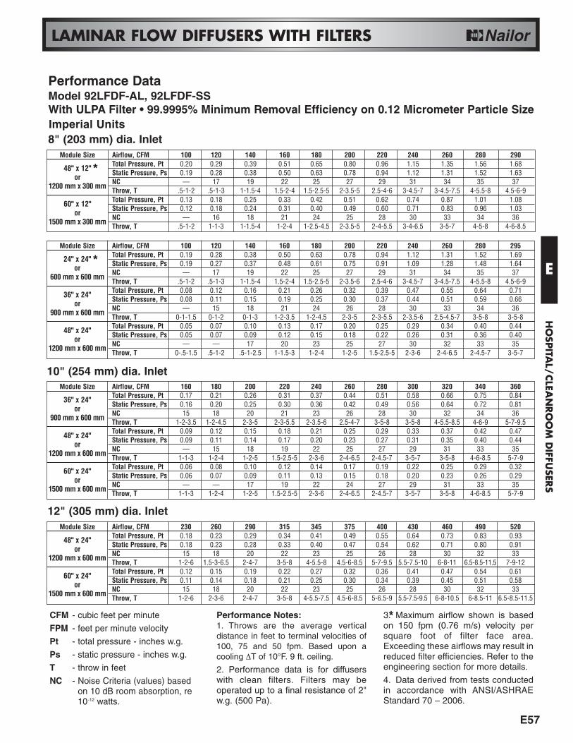
LAMINAR FLOW DIFFUSERS WITH FILTERS
8" (203 mm) dia. InletModule Size Airflow, CFM 100 120 140 160 180 200 220 240 260 280 290
48" x 12" Total Pressure, Pt 0.20 0.29 0.39 0.51 0.65 0.80 0.96 1.15 1.35 1.56 1.68
or Static Pressure, Ps 0.19 0.28 0.38 0.50 0.63 0.78 0.94 1.12 1.31 1.52 1.63
1200 mm x 300 mm NC — 17 19 22 25 27 29 31 34 35 37Throw, T .5-1-2 .5-1-3 1-1.5-4 1.5-2-4 1.5-2.5-5 2-3.5-5 2.5-4-6 3-4.5-7 3-4.5-7.5 4-5.5-8 4.5-6-9
60" x 12" Total Pressure, Pt 0.13 0.18 0.25 0.33 0.42 0.51 0.62 0.74 0.87 1.01 1.08
or Static Pressure, Ps 0.12 0.18 0.24 0.31 0.40 0.49 0.60 0.71 0.83 0.96 1.03
1500 mm x 300 mm NC — 16 18 21 24 25 28 30 33 34 36Throw, T .5-1-2 1-1-3 1-1.5-4 1-2-4 1-2.5-4.5 2-3.5-5 2-4-5.5 3-4-6.5 3-5-7 4-5-8 4-6-8.5
10" (254 mm) dia. Inlet
12" (305 mm) dia. Inlet
CFM - cubic feet per minute
FPM - feet per minute velocity
Pt - total pressure - inches w.g.
Ps - static pressure - inches w.g.
T - throw in feet
NC - Noise Criteria (values) based on 10 dB room absorption, re 10-12 watts.
Performance Notes:1. Throws are the average verticaldistance in feet to terminal velocities of100, 75 and 50 fpm. Based upon acooling ∆T of 10°F. 9 ft. ceiling.
2. Performance data is for diffuserswith clean filters. Filters may beoperated up to a final resistance of 2"w.g. (500 Pa).
3. Maximum airflow shown is basedon 150 fpm (0.76 m/s) velocity persquare foot of filter face area.Exceeding these airflows may result inreduced filter efficiencies. Refer to theengineering section for more details.
4. Data derived from tests conductedin accordance with ANSI/ASHRAEStandard 70 – 2006.
*
Module Size Airflow, CFM 100 120 140 160 180 200 220 240 260 280 295
24" x 24" Total Pressure, Pt 0.19 0.28 0.38 0.50 0.63 0.78 0.94 1.12 1.31 1.52 1.69
or Static Pressure, Ps 0.19 0.27 0.37 0.48 0.61 0.75 0.91 1.09 1.28 1.48 1.64
600 mm x 600 mm NC — 17 19 22 25 27 29 31 34 35 37Throw, T .5-1-2 .5-1-3 1-1.5-4 1.5-2-4 1.5-2.5-5 2-3.5-6 2.5-4-6 3-4.5-7 3-4.5-7.5 4-5.5-8 4.5-6-9
36" x 24" Total Pressure, Pt 0.08 0.12 0.16 0.21 0.26 0.32 0.39 0.47 0.55 0.64 0.71
or Static Pressure, Ps 0.08 0.11 0.15 0.19 0.25 0.30 0.37 0.44 0.51 0.59 0.66
900 mm x 600 mm NC — 15 18 21 24 26 28 30 33 34 36Throw, T 0-1-1.5 0-1-2 0-1-3 1-2-3.5 1-2-4.5 2-3-5 2-3-5.5 2-3.5-6 2.5-4.5-7 3-5-8 3-5-8
48" x 24" Total Pressure, Pt 0.05 0.07 0.10 0.13 0.17 0.20 0.25 0.29 0.34 0.40 0.44
or Static Pressure, Ps 0.05 0.07 0.09 0.12 0.15 0.18 0.22 0.26 0.31 0.36 0.40
1200 mm x 600 mm NC — — 17 20 23 25 27 30 32 33 35Throw, T 0-.5-1.5 .5-1-2 .5-1-2.5 1-1.5-3 1-2-4 1-2-5 1.5-2.5-5 2-3-6 2-4-6.5 2-4.5-7 3-5-7
Module Size Airflow, CFM 160 180 200 220 240 260 280 300 320 340 360
36" x 24" Total Pressure, Pt 0.17 0.21 0.26 0.31 0.37 0.44 0.51 0.58 0.66 0.75 0.84
or Static Pressure, Ps 0.16 0.20 0.25 0.30 0.36 0.42 0.49 0.56 0.64 0.72 0.81
900 mm x 600 mm NC 15 18 20 21 23 26 28 30 32 34 36Throw, T 1-2-3.5 1-2-4.5 2-3-5 2-3-5.5 2-3.5-6 2.5-4-7 3-5-8 3-5-8 4-5.5-8.5 4-6-9 5-7-9.5
48" x 24" Total Pressure, Pt 0.09 0.12 0.15 0.18 0.21 0.25 0.29 0.33 0.37 0.42 0.47
or Static Pressure, Ps 0.09 0.11 0.14 0.17 0.20 0.23 0.27 0.31 0.35 0.40 0.44
1200 mm x 600 mm NC — 15 18 19 22 25 27 29 31 33 35Throw, T 1-1-3 1-2-4 1-2-5 1.5-2.5-5 2-3-6 2-4-6.5 2-4.5-7 3-5-7 3-5-8 4-6-8.5 5-7-9
60" x 24" Total Pressure, Pt 0.06 0.08 0.10 0.12 0.14 0.17 0.19 0.22 0.25 0.29 0.32
or Static Pressure, Ps 0.06 0.07 0.09 0.11 0.13 0.15 0.18 0.20 0.23 0.26 0.29
1500 mm x 600 mm NC — — 17 19 22 24 27 29 31 33 35Throw, T 1-1-3 1-2-4 1-2-5 1.5-2.5-5 2-3-6 2-4-6.5 2-4.5-7 3-5-7 3-5-8 4-6-8.5 5-7-9
Module Size Airflow, CFM 230 260 290 315 345 375 400 430 460 490 520
48" x 24" Total Pressure, Pt 0.18 0.23 0.29 0.34 0.41 0.49 0.55 0.64 0.73 0.83 0.93
or Static Pressure, Ps 0.18 0.23 0.28 0.33 0.40 0.47 0.54 0.62 0.71 0.80 0.91
1200 mm x 600 mm NC 15 18 20 22 23 25 26 28 30 32 33Throw, T 1-2-6 1.5-3-6.5 2-4-7 3-5-8 4-5.5-8 4.5-6-8.5 5-7-9.5 5.5-7.5-10 6-8-11 6.5-8.5-11.5 7-9-12
60" x 24" Total Pressure, Pt 0.12 0.15 0.19 0.22 0.27 0.32 0.36 0.41 0.47 0.54 0.61
or Static Pressure, Ps 0.11 0.14 0.18 0.21 0.25 0.30 0.34 0.39 0.45 0.51 0.58
1500 mm x 600 mm NC 15 18 20 22 23 25 26 28 30 32 33Throw, T 1-2-6 2-3-6 2-4-7 3-5-8 4-5.5-7.5 4.5-6-8.5 5-6.5-9 5.5-7.5-9.5 6-8-10.5 6-8.5-11 6.5-8.5-11.5
*
*
Imperial Units
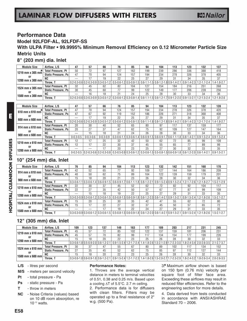
Performance DataModel 92LFDF-AL, 92LFDF-SSWith ULPA Filter • 99.9995% Minimum Removal Efficiency on 0.12 Micrometer Particle Size
E
HO
SPITA
L/CLEA
NRO
OM
DIFFU
SERS
E58
LAMINAR FLOW DIFFUSERS WITH FILTERS
L/S - litres per second
M/S - meters per second velocity
Pt - total pressure - Pa
Ps - static pressure - Pa
T - throw in meters
NC - Noise Criteria (values) based on 10 dB room absorption, re 10-12 watts.
Performance Notes:1. Throws are the average verticaldistance in meters to terminal velocitiesof 0.51, 0.38 and 0.25 m/s. Based upona cooling ∆T of 5.5°C. 2.7 m ceiling.2. Performance data is for diffuserswith clean filters. Filters may beoperated up to a final resistance of 2"w.g. (500 Pa).
3. Maximum airflow shown is basedon 150 fpm (0.76 m/s) velocity persquare foot of filter face area.Exceeding these airflows may result inreduced filter efficiencies. Refer to theengineering section for more details.
4. Data derived from tests conductedin accordance with ANSI/ASHRAEStandard 70 – 2006.
*
Metric Units8" (203 mm) dia. Inlet
Module Size Airflow, L/S 47 57 66 76 85 94 104 113 123 132 137
1219 mm x 305 mm Total Pressure, Pt 50 72 97 127 162 199 239 286 336 388 418
or Static Pressure, Ps 47 70 94 124 157 194 234 278 326 378 405
1200 mm x 300 mm NC — 17 19 22 25 27 29 31 34 35 37Throw, T 0.2-0.3-0.6 0.2-0.3-0.9 0.3-0.5-1.2 0.5-0.6-1.2 0.5-0.8-1.5 0.6-1.1-1.5 0.8-1.2-1.8 0.9-1.4-2.1 0.9-1.4-2.3 1.2-1.7-2.4 1.4-1.8-2.7
1524 mm x 305 mm Total Pressure, Pt 32 45 62 82 104 127 154 184 216 251 268
or Static Pressure, Ps 30 45 60 77 99 122 149 177 206 239 256
1500 mm x 300 mm NC — 16 18 21 24 25 28 30 33 34 36Throw, T 0.2-0.3-0.6 0.3-0.3-0.9 0.3-0.5-1.2 0.3-0.6-1.2 0.3-0.8-1.4 0.6-1.1-1.5 0.6-1.2-1.7 0.9-1.2-2.0 0.9-1.5-2.1 1.2-1.5-2.4 1.2-1.8-2.6
10" (254 mm) dia. Inlet
12" (305 mm) dia. Inlet
Module Size Airflow, L/S 47 57 66 76 85 94 104 113 123 132 139
610 mm x 610 mm Total Pressure, Pt 47 70 94 124 157 194 234 278 326 378 420
or Static Pressure, Ps 47 67 92 119 152 186 226 271 318 368 408
600 mm x 600 mm NC — 17 19 22 25 27 29 31 34 35 37Throw, T 0.2-0.3-0.6 0.2-0.3-0.9 0.3-0.5-1.2 0.5-0.6-1.2 0.5-0.8-1.5 0.6-1.1-1.8 0.8-1.2-1.8 0.9-1.4-2.1 0.9-1.4-2.3 1.2-1.7-2.4 1.4-1.8-2.7
914 mm x 610 mm Total Pressure, Pt 20 30 40 52 65 80 97 117 137 159 177
or Static Pressure, Ps 20 27 37 47 62 75 92 109 127 147 164
900 mm x 600 mm NC — 15 18 21 24 26 28 30 33 34 36Throw, T 0-0.3-0.5 0-0.3-0.6 0-0.3-0.9 0.3-0.6-1.1 0.3-0.6-1.4 0.6-0.9-1.5 0.6-0.9-1.7 0.6-1.1-1.8 0.8-1.4-2.1 0.9-1.5-2.4 0.9-1.5-2.4
1219 mm x 610 mm Total Pressure, Pt 12 17 25 32 42 50 62 72 85 99 109
or Static Pressure, Ps 12 17 22 30 37 45 55 65 77 89 99
1200 mm x 600 mm NC — — 17 20 23 25 27 30 32 33 35Throw, T 0-0.2-0.5 0.2-0.3-0.6 0.2-0.3-0.8 0.3-0.5-0.9 0.3-0.6-1.2 0.3-0.6-1.5 0.5-0.8-1.5 0.6-0.9-1.8 0.6-1.2-2.0 0.6-1.4-2.1 0.9-1.5-2.1
Module Size Airflow, L/S 76 85 94 104 113 123 132 142 151 160 170
914 mm x 610 mm Total Pressure, Pt 42 52 65 77 92 109 127 144 164 186 209
or Static Pressure, Ps 40 50 62 75 89 104 122 139 159 179 201
900 mm x 600 mm NC 15 18 20 21 23 26 28 30 32 34 36Throw, T 0.3-0.6-1.1 0.3-0.6-1.4 0.6-0.9-1.5 0.6-0.9-1.7 0.6-1.1-1.8 0.8-1.2-2.1 0.9-1.5-2.4 0.9-1.5-2.4 1.2-1.7-2.6 1.2-1.8-2.7 1.5-2.1-2.9
1219 mm x 610 mm Total Pressure, Pt 22 30 37 45 52 62 72 82 92 104 117
or Static Pressure, Ps 22 27 35 42 50 57 67 77 87 99 109
1200 mm x 600 mm NC — 15 18 19 22 25 27 29 31 33 35Throw, T 0.3-0.3-0.9 0.3-0.6-1.2 0.3-0.6-1.5 0.5-0.8-1.5 0.6-0.9-1.8 0.6-1.2-2.0 0.6-1.4-2.1 0.9-1.5-2.1 0.9-1.5-2.4 1.2-1.8-2.6 1.5-2.1-2.7
1524 mm x 610 mm Total Pressure, Pt 15 20 25 30 35 42 47 55 62 72 80
or Static Pressure, Ps 15 17 22 27 32 37 45 50 57 65 72
1500 mm x 600 mm NC — — 17 19 22 24 27 29 31 33 35Throw, T 0.3-0.3-0.9 0.3-0.6-1.2 0.3-0.6-1.5 0.5-0.8-1.5 0.6-0.9-1.8 0.6-1.2-2.0 0.6-1.4-2.1 0.9-1.5-2.1 0.9-1.5-2.4 1.2-1.8-2.6 1.5-2.1-2.7
Module Size Airflow, L/S 109 123 137 149 163 177 189 203 217 231 245
1219 mm x 610 mm Total Pressure, Pt 45 57 72 85 102 122 137 159 181 206 231
or Static Pressure, Ps 45 57 70 82 99 117 134 154 177 199 226
1200 mm x 600 mm NC 15 18 20 22 23 25 26 28 30 32 33Throw, T 0.3-0.6-1.8 0.5-0.9-2.0 0.6-1.2-2.1 0.9-1.5-2.4 1.2-1.7-2.4 1.4-1.8-2.6 1.5-2.1-2.9 1.7-2.3-3.0 1.8-2.4-3.4 2.0-2.6-3.5 2.1-2.7-3.7
1524 mm x 610 mm Total Pressure, Pt 30 37 47 55 67 80 89 102 117 134 152
or Static Pressure, Ps 27 35 45 52 62 75 85 97 112 127 144
1500 mm x 600 mm NC 15 18 20 22 23 25 26 28 30 32 33Throw, T 0.3-0.6-1.8 0.6-0.9-1.8 0.6-1.2-2.1 0.9-1.5-2.4 1.2-1.7-2.3 1.4-1.8-2.6 1.5-2.0-2.7 1.7-2.3-2.9 1.8-2.4-3.2 1.8-2.6-3.4 2.0-2.6-3.5
*
*
Performance DataModel 92LFDF-AL, 92LFDF-SSWith ULPA Filter • 99.9995% Minimum Removal Efficiency on 0.12 Micrometer Particle Size
E
HO
SPIT
AL/
CLE
AN
RO
OM
DIF
FUSE
RS

LAMINAR FLOW DIFFUSERS
Performance Notes:1. CFM = Airflow in cubic feet per minute.
2. Pt = Total pressure, inches w.g.
3. Ps = Static pressure, inches w.g.
4. NC (Noise Criteria) values are based upon 10dB roomabsorption, re 10-12 watts. Blank (-) indicates NC of below 15.
5. Face velocities and average velocities are in feet perminute.
6. Average velocities are measured below the face of the dif-fuser with a cooling ∆T of 5°F.
7. Average velocity is based on one diffuser handling thespecified air volume.
8. Data derived from tests conducted in accordance withANSI/ASHRAE Standard 70 – 2006.
Performance DataModels 92LFDM-AL, 92LFDM-SS • Medium Capacity • Dual ChamberImperial Units
TotalCFM
Face Velocity/cfm/sq. ft.
8" Inlet 10" Inlet 12" InletAverage Velocity
Distance Below Diffuser Face (ft)Pt Ps NC Pt Ps NC Pt Ps NC 1 2 3 4 5 6 7
200 50 .08 .06 16 .04 .03 - .03 .03 - 81 70 62 59 54 48 45240 60 .11 .09 21 .06 .04 - .05 .04 - 93 80 70 64 57 51 48280 70 .16 .12 27 .08 .06 19 .06 .06 - 105 90 77 70 61 54 50320 80 .20 .15 29 .10 .08 21 .08 .07 - 116 96 83 75 64 56 53360 90 .26 .20 33 .13 .10 25 .11 .09 18 128 101 89 80 68 59 55400 100 .32 .24 37 .16 .13 29 .13 .11 22 145 109 95 86 71 60 56
24" x 24" Module
TotalCFM
Face Velocity/cfm/sq. ft.
10" Inlet 12" Inlet 14" InletAverage Velocity
Distance Below Diffuser Face (ft)Pt Ps NC Pt Ps NC Pt Ps NC 1 2 3 4 5 6 7
400 50 .09 .06 26 .05 .03 20 .03 .02 - 92 79 70 67 61 55 51480 60 .13 .09 31 .07 .05 25 .05 .03 19 106 91 79 73 65 58 54560 70 .18 .12 37 .10 .07 31 .06 .05 25 119 102 87 79 69 61 57640 80 .24 .15 39 .13 .09 33 .08 .06 27 132 109 94 85 73 64 60720 90 .30 .20 43 .16 .11 37 .11 .08 31 145 115 101 91 77 67 63800 100 .37 .24 47 .20 .14 41 .13 .10 35 165 124 108 98 81 68 64
24" x 48" Module
TotalCFM
Face Velocity/cfm/sq. ft.
12" Inlet 14" Inlet 16" InletAverage Velocity
Distance Below Diffuser Face (ft)Pt Ps NC Pt Ps NC Pt Ps NC 1 2 3 4 5 6 7
500 50 .07 .04 25 .04 .03 19 .03 .02 - 97 83 74 70 64 58 54600 60 .09 .06 30 .06 .04 24 .04 .02 18 111 96 83 77 68 61 57700 70 .13 .08 36 .08 .05 30 .05 .03 24 125 107 91 83 72 64 60800 80 .17 .10 38 .10 .07 32 .06 .04 26 139 114 99 89 77 67 63900 90 .21 .13 42 .13 .09 36 .08 .06 30 152 121 106 96 81 70 661000 100 .26 .16 45 .16 .11 40 .10 .07 34 173 130 113 103 85 71 67
24" x 60" Module
PDHC92LFDM 3-21-11
TotalCFM
Face Velocity/cfm/sq. ft.
10" Inlet 12" Inlet 14" InletAverage Velocity
Distance Below Diffuser Face (ft)Pt Ps NC Pt Ps NC Pt Ps NC 1 2 3 4 5 6 7
300 50 .06 .04 19 .03 .03 - .02 .02 - 86 74 66 63 57 52 48360 60 .09 .06 24 .05 .04 18 .03 .02 - 100 86 74 69 61 55 51420 70 .12 .08 30 .07 .05 24 .04 .03 18 112 96 82 74 65 57 54480 80 .16 .11 32 .09 .06 26 .05 .04 20 124 102 88 80 69 60 56540 90 .20 .14 36 .11 .08 30 .06 .05 24 136 108 95 86 72 63 59600 100 .25 .17 40 .14 .10 34 .08 .06 28 155 117 102 92 76 64 60
24" x 36" Module
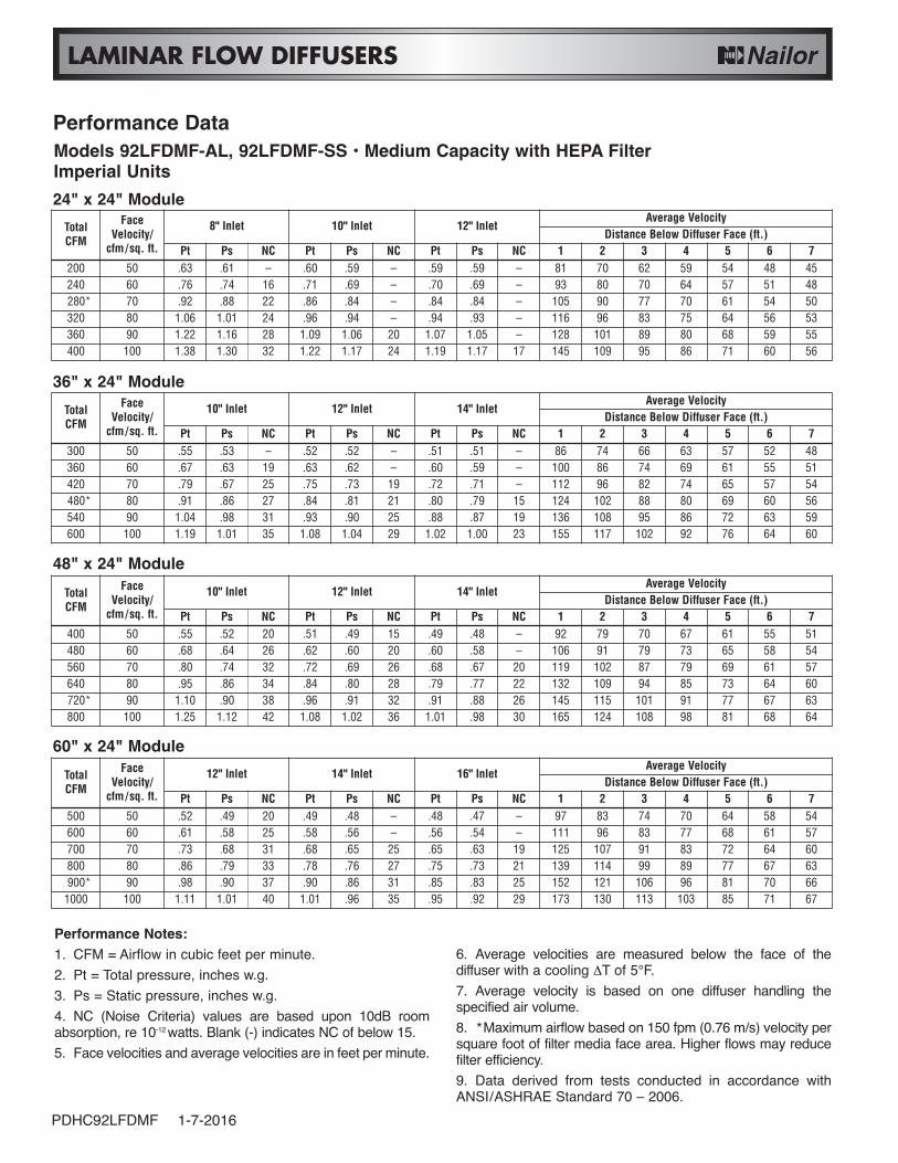
LAMINAR FLOW DIFFUSERS
Performance Notes:1. CFM = Airflow in cubic feet per minute.2. Pt = Total pressure, inches w.g.3. Ps = Static pressure, inches w.g.4. NC (Noise Criteria) values are based upon 10dB roomabsorption, re 10-12 watts. Blank (-) indicates NC of below 15.5. Face velocities and average velocities are in feet per minute.
6. Average velocities are measured below the face of thediffuser with a cooling ΔT of 5°F.7. Average velocity is based on one diffuser handling thespecified air volume.8. *Maximum airflow based on 150 fpm (0.76 m/s) velocity persquare foot of filter media face area. Higher flows may reducefilter efficiency.9. Data derived from tests conducted in accordance withANSI/ASHRAE Standard 70 – 2006.
Performance DataModels 92LFDMF-AL, 92LFDMF-SS • Medium Capacity with HEPA FilterImperial Units24" x 24" Module
48" x 24" Module
60" x 24" Module
PDHC92LFDMF 1-7-2016
36" x 24" Module
TotalCFM
FaceVelocity/
cfm/sq. ft.
8" Inlet 10" Inlet 12" InletAverage Velocity
Distance Below Diffuser Face (ft.)Pt Ps NC Pt Ps NC Pt Ps NC 1 2 3 4 5 6 7
200 50 .63 .61 – .60 .59 – .59 .59 – 81 70 62 59 54 48 45240 60 .76 .74 16 .71 .69 – .70 .69 – 93 80 70 64 57 51 48280* 70 .92 .88 22 .86 .84 – .84 .84 – 105 90 77 70 61 54 50320 80 1.06 1.01 24 .96 .94 – .94 .93 – 116 96 83 75 64 56 53360 90 1.22 1.16 28 1.09 1.06 20 1.07 1.05 – 128 101 89 80 68 59 55400 100 1.38 1.30 32 1.22 1.17 24 1.19 1.17 17 145 109 95 86 71 60 56
TotalCFM
FaceVelocity/
cfm/sq. ft.
10" Inlet 12" Inlet 14" InletAverage Velocity
Distance Below Diffuser Face (ft.)Pt Ps NC Pt Ps NC Pt Ps NC 1 2 3 4 5 6 7
300 50 .55 .53 – .52 .52 – .51 .51 – 86 74 66 63 57 52 48360 60 .67 .63 19 .63 .62 – .60 .59 – 100 86 74 69 61 55 51420 70 .79 .67 25 .75 .73 19 .72 .71 – 112 96 82 74 65 57 54480* 80 .91 .86 27 .84 .81 21 .80 .79 15 124 102 88 80 69 60 56540 90 1.04 .98 31 .93 .90 25 .88 .87 19 136 108 95 86 72 63 59600 100 1.19 1.01 35 1.08 1.04 29 1.02 1.00 23 155 117 102 92 76 64 60
TotalCFM
FaceVelocity/
cfm/sq. ft.
10" Inlet 12" Inlet 14" InletAverage Velocity
Distance Below Diffuser Face (ft.)Pt Ps NC Pt Ps NC Pt Ps NC 1 2 3 4 5 6 7
400 50 .55 .52 20 .51 .49 15 .49 .48 – 92 79 70 67 61 55 51480 60 .68 .64 26 .62 .60 20 .60 .58 – 106 91 79 73 65 58 54560 70 .80 .74 32 .72 .69 26 .68 .67 20 119 102 87 79 69 61 57640 80 .95 .86 34 .84 .80 28 .79 .77 22 132 109 94 85 73 64 60720* 90 1.10 .90 38 .96 .91 32 .91 .88 26 145 115 101 91 77 67 63800 100 1.25 1.12 42 1.08 1.02 36 1.01 .98 30 165 124 108 98 81 68 64
TotalCFM
FaceVelocity/
cfm/sq. ft.
12" Inlet 14" Inlet 16" InletAverage Velocity
Distance Below Diffuser Face (ft.)Pt Ps NC Pt Ps NC Pt Ps NC 1 2 3 4 5 6 7
500 50 .52 .49 20 .49 .48 – .48 .47 – 97 83 74 70 64 58 54600 60 .61 .58 25 .58 .56 – .56 .54 – 111 96 83 77 68 61 57700 70 .73 .68 31 .68 .65 25 .65 .63 19 125 107 91 83 72 64 60800 80 .86 .79 33 .78 .76 27 .75 .73 21 139 114 99 89 77 67 63900* 90 .98 .90 37 .90 .86 31 .85 .83 25 152 121 106 96 81 70 66
1000 100 1.11 1.01 40 1.01 .96 35 .95 .92 29 173 130 113 103 85 71 67