laser doppler anemometry - purdue engineeringaae520/ldv-lecture-rev3.pdf · laser doppler...
TRANSCRIPT
AAE 520 Experimental Aerodynamics
Purdue University - School of Aeronautics and Astronautics
Laser Doppler AnemometryIntroduction to principles and applications
adapted from DANTEC literature by John Sullivan, Purdue AAE.Edited by S.P. Schneider, Purdue AAE.

AAE 520 Experimental Aerodynamics
Purdue University - School of Aeronautics and Astronautics
Why Measure?
• Almost all industrial flows are turbulent.• Almost all naturally occurring flows on earth, in oceans,
and atmosphere are turbulent.
Turbulent motion is 3-D, vortical, and diffusive governing Navier-Stokes equations are very hard(or impossible) to solve.
Measurements are easier (easy?)
ρ∂τ∂
ρ ∂∂
DuDt X
f pX
i ij
ji
j
= + −

AAE 520 Experimental Aerodynamics
Purdue University - School of Aeronautics and Astronautics
Characteristics of LDA
• Invented by Yeh and Cummins in 1964• Velocity measurements in Fluid Dynamics (gas, liquid)• Up to 3 velocity components• Non-intrusive measurements (optical technique)• Absolute measurement technique (no calibration
required)• Very high accuracy• Very high spatial resolution due to small measurement
volume• Tracer particles are required
AAE 520 Experimental Aerodynamics
Purdue University - School of Aeronautics and Astronautics
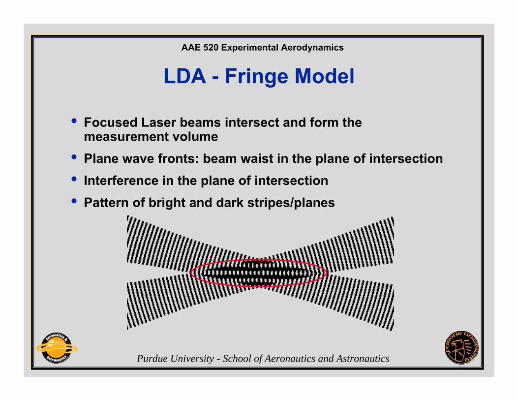
LDA - Fringe Model
• Focused Laser beams intersect and form the measurement volume
• Plane wave fronts: beam waist in the plane of intersection• Interference in the plane of intersection• Pattern of bright and dark stripes/planes

AAE 520 Experimental Aerodynamics
Purdue University - School of Aeronautics and Astronautics
Flow with particles
d (known)
Velocity = distance/time
t (measured)
Signal
Time
LaserBraggCell backscattered light
measuring volume
Detector
Processor

AAE 520 Experimental Aerodynamics
Purdue University - School of Aeronautics and Astronautics
LDA - Fringe Model• The fringe model
assumes as a way of visualization that the two intersecting beams form a fringe pattern of high and low intensity.
• When the particle traverses this fringe pattern the scattered light fluctuates in intensity with a frequency equal to the velocity of the particle divided by the fringe spacing.
f=frequencyv=particle velocityθ=angle between laser beamsλ=wavelength of laser lightSee Adrian paper in Goldstein
AAE 520 Experimental Aerodynamics
Purdue University - School of Aeronautics and Astronautics
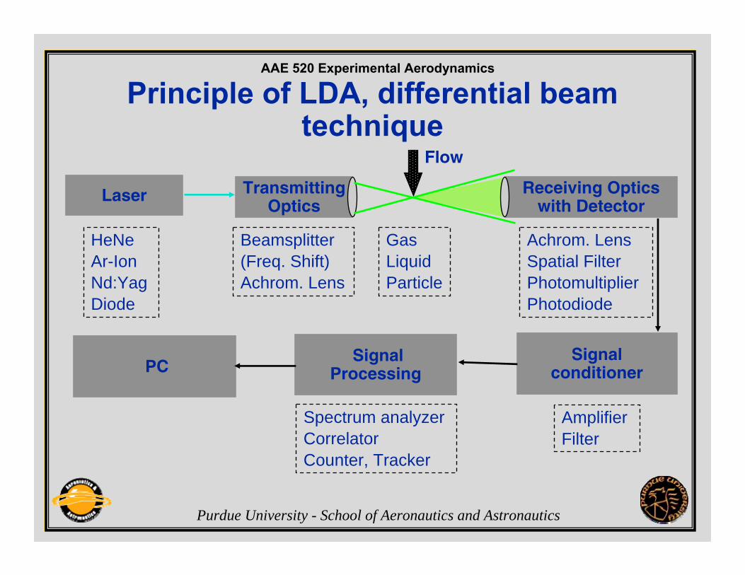
Principle of LDA, differential beam technique
Laser
SignalProcessing
TransmittingOptics
Receiving Opticswith Detector
Signalconditioner
Flow
HeNeAr-IonNd:YagDiode
Beamsplitter(Freq. Shift)Achrom. Lens
GasLiquidParticle
Achrom. LensSpatial FilterPhotomultiplierPhotodiode
Spectrum analyzerCorrelatorCounter, Tracker
AmplifierFilter
PC

AAE 520 Experimental Aerodynamics
Purdue University - School of Aeronautics and Astronautics
Laser, Characteristics and Requirements
• Monochrome• Coherent• Linearly polarized• Low divergence
(collimator)
• Gaussian intensity distribution
Laser
L-Diode collimator
Laser
AAE 520 Experimental Aerodynamics
Purdue University - School of Aeronautics and Astronautics
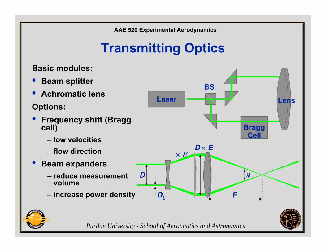
Transmitting OpticsBasic modules:• Beam splitter• Achromatic lensOptions: • Frequency shift (Bragg
cell)– low velocities– flow direction
• Beam expanders– reduce measurement
volume– increase power density
Laser
BraggCell
BS
F
D × E
ϑ
× Ε
D
DL
Lens

AAE 520 Experimental Aerodynamics
Purdue University - School of Aeronautics and Astronautics
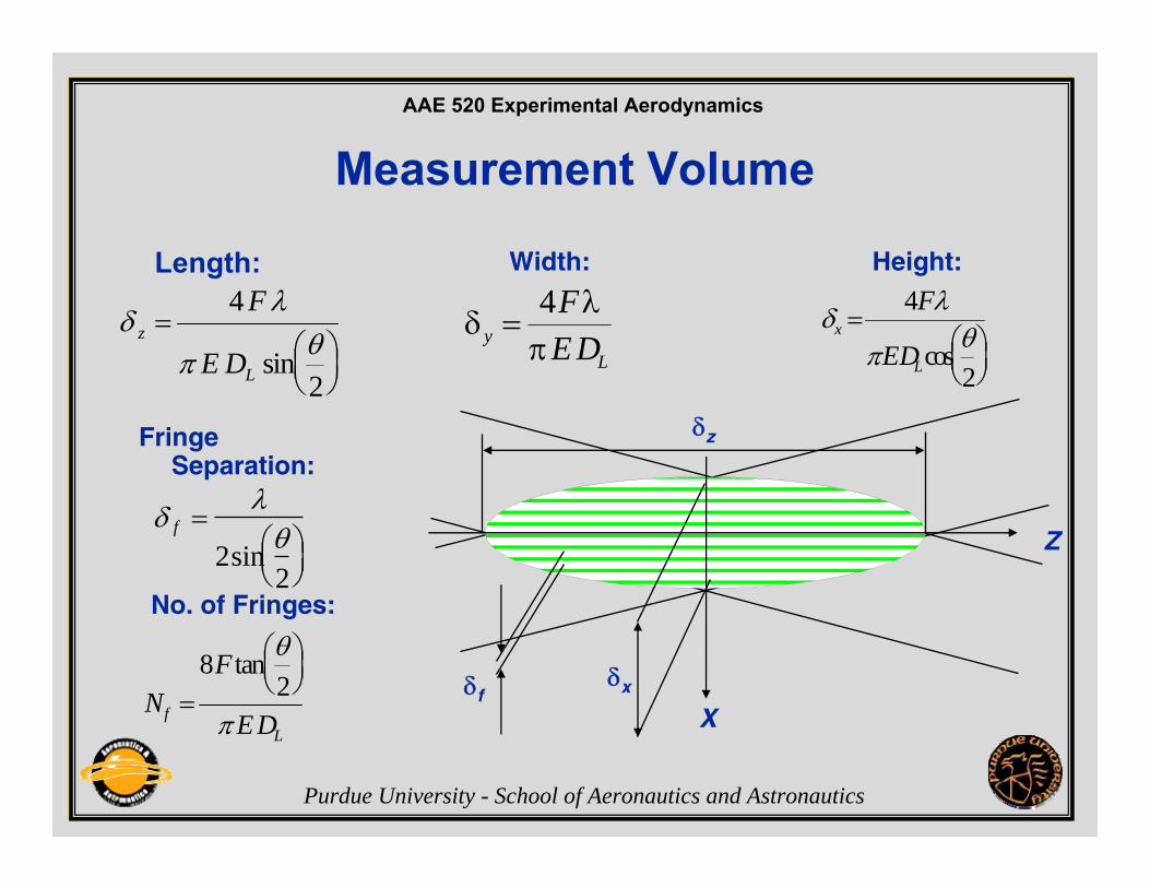
Measurement Volume
• The transmitting system generates the measurement volume
• The measurement volume has a Gaussian intensity distribution in all 3 dimensions
• The measurement volume is an ellipsoid
• Dimensions/diameters δx, δy and δz are given by the 1/e2 intensity points
F
θDL
Y
Z
X
TransmittingSystem
MeasurementVolume
IntensityDistribution
0 1/e 21
δz
δx
δy X
Z
Y
AAE 520 Experimental Aerodynamics
Purdue University - School of Aeronautics and Astronautics
Measurement Volume
Length:
ϑ
Width: Height:
No. of Fringes:
δλ
π θz
L
F
E D=
⎛⎝⎜
⎞⎠⎟
4
2sin
δλ
πyL
FE D
=4 δ
λ
πθx
L
F
ED=
⎛⎝⎜
⎞⎠⎟
4
2cos
NF
EDfL
=
⎛⎝⎜
⎞⎠⎟
82
tan θ
π
δz
δx
X
Z
δf
Fringe Separation:
δ λθf =
⎛⎝⎜
⎞⎠⎟
22
sin

AAE 520 Experimental Aerodynamics
Purdue University - School of Aeronautics and Astronautics
Lenses
Interferencefiltre
Photomultiplier
Receiving Systems
• Receiving Optics– Receiving optics– Multimode fibre
acting as spatial filtre
– Interference filtre• Detector
– Photomultiplier– Photodiode
Multimodefibre

AAE 520 Experimental Aerodynamics
Purdue University - School of Aeronautics and Astronautics
System ConfigurationsForward scatterand side scatter(off-axis)• Difficult to align,• vibration
sensitive
Backscatter• Easy to align• User friendly
Receiving Opticswith Detector
TransmittingOptics
Flow Receiving Optics
with Detector
FlowLaser
BraggCell
Detector Transmitting and Receiving Optics

AAE 520 Experimental Aerodynamics
Purdue University - School of Aeronautics and Astronautics
Backscatter Configuration
Laser BraggCell
Coloursplitter
PM
PM
Fibre manipulators
Single mode polarisationpreserving fibres
Flow
Back scattered light
Multimodefibre
Multimodefibre
Interferencefiltres
Coloursplitter
Single modefibres

AAE 520 Experimental Aerodynamics
Purdue University - School of Aeronautics and Astronautics
• Particles moving in either the forward or reverse direction willproduce identical signals and frequencies.
Directional Ambiguity / Frequency Shift
fmax
fshiftfmin
f
uumin umax
umin umax• With frequency shift in one beam relative to the other, the
interference fringes appear to move at the shift frequency. • With frequency shifting, negative velocities can be distinguished.
no shift shift

AAE 520 Experimental Aerodynamics
Purdue University - School of Aeronautics and Astronautics
Frequency Shift / Bragg Cell
• Acousto-optical Modulator• Bragg cell requires a signal
generator (typically: 40 MHz)• Frequency of laser light is
increased by the shift frequency
• Beam correction by means of additional prisms
PiezoelectricTransducer
fs = 40 MHz
Absorber
wave front
Laser ϕΒ
fL
fL + fS
AAE 520 Experimental Aerodynamics
Purdue University - School of Aeronautics and Astronautics
3-D LDA Applications
• Measurements of boundary layer separation in wind tunnels
• Turbulent mixing and flame investigations in combustors• Studies of boundary layer-wake interactions and
instabilities in turbines• Investigations of flow structure, heat transfer, and
instabilities in heat exchangers• Studies of convection and forced cooling in nuclear
reactor models • Measurements around ship models in towing tanks
AAE 520 Experimental Aerodynamics
Purdue University - School of Aeronautics and Astronautics
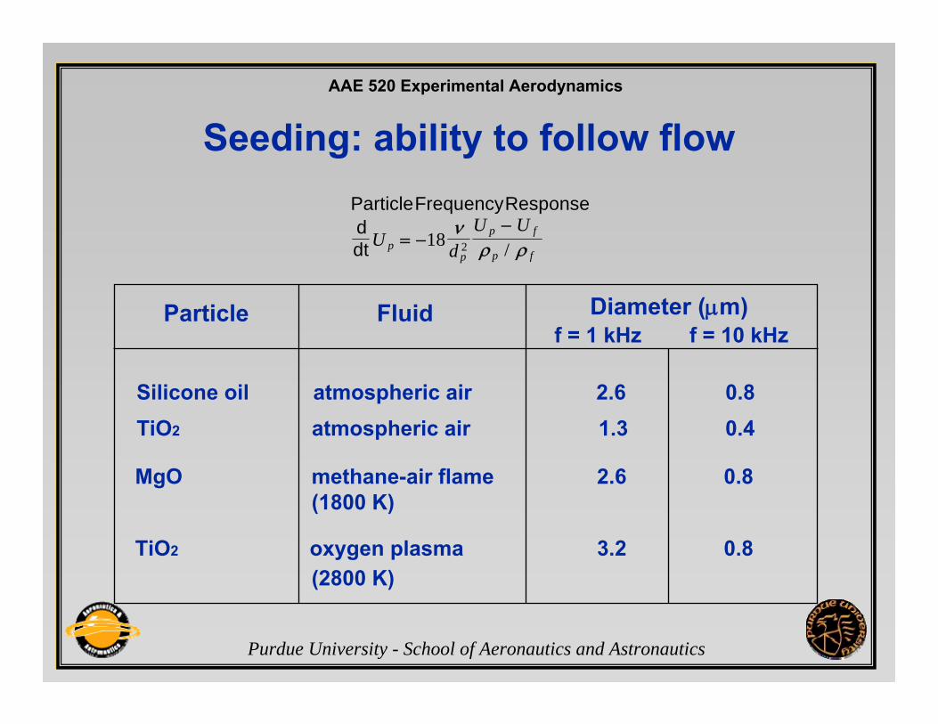
Seeding: ability to follow flowParticleFrequencyResponseddt U d
U Up
p
p f
p f= −
−18 2
νρ ρ/
Particle Fluid Diameter (μm)f = 1 kHz f = 10 kHz
Silicone oil atmospheric air 2.6 0.8TiO2 atmospheric air 1.3 0.4
TiO2 oxygen plasma 3.2 0.8(2800 K)
MgO methane-air flame 2.6 0.8(1800 K)
AAE 520 Experimental Aerodynamics
Purdue University - School of Aeronautics and Astronautics
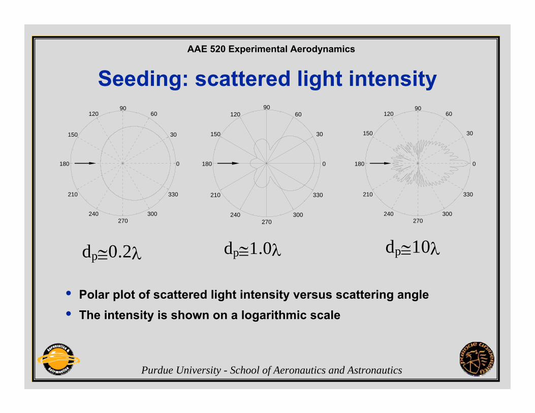
Seeding: scattered light intensity
180 0
90
270
210
150
240
120
300
60
330
30
180 0
330210
240 300270
150
12090
60
30
180 0
210
150
240
120
270
9060
300
30
330
dp≅0.2λ dp≅1.0λ dp≅10λ
• Polar plot of scattered light intensity versus scattering angle • The intensity is shown on a logarithmic scale

AAE 520 Experimental Aerodynamics
Purdue University - School of Aeronautics and Astronautics
Signal Characteristics
• Sources of noise in the LDA signal:– Photodetection shot noise.– Secondary electronic noise, thermal noise from preamplifier circuit– Higher order laser modes (optical noise).– Light scattered from outside the measurement volume, dirt, scratched
windows, ambient light, multiple particles, etc.– Unwanted reflections (windows, lenses, mirrors, etc).
• Goal: Select laser power, seeding, optical parameters, etc. to maximize the SNR.

AAE 520 Experimental Aerodynamics
Purdue University - School of Aeronautics and Astronautics
Measurement of air flow around ahelicopter rotor model in a wind tunnel
Photo courtesy of University of Bristol, UK

AAE 520 Experimental Aerodynamics
Purdue University - School of Aeronautics and Astronautics
Measurement of flow field around a 1:5 scale car model in a wind tunnel
Photo courtesy of Mercedes-Benz, Germany
AAE 520 Experimental Aerodynamics
Purdue University - School of Aeronautics and Astronautics
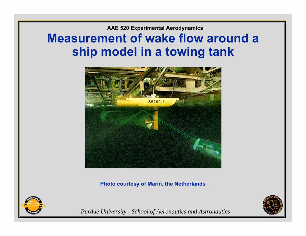
Measurement of wake flow around a ship model in a towing tank
Photo courtesy of Marin, the Netherlands

AAE 520 Experimental Aerodynamics
Purdue University - School of Aeronautics and Astronautics
Measurement of air flow field around a ship model in a wind tunnel
Photo courtesy of University of Bristol, UK

AAE 520 Experimental Aerodynamics
Purdue University - School of Aeronautics and Astronautics
Wake flow field behind hangar

AAE 520 Experimental Aerodynamics
Purdue University - School of Aeronautics and Astronautics
Measurement of flow around a ship propeller in a cavitation tank
AAE 520 Experimental Aerodynamics
Purdue University - School of Aeronautics and Astronautics
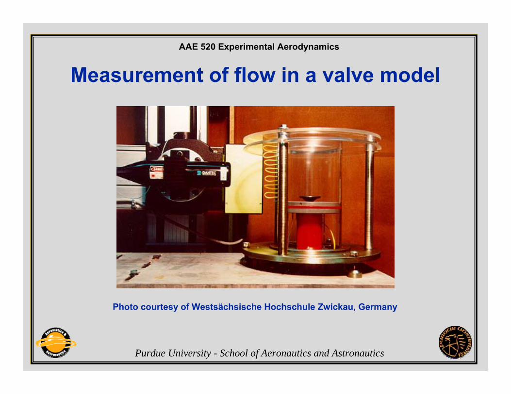
Measurement of flow in a valve model
Photo courtesy of Westsächsische Hochschule Zwickau, Germany

AAE 520 Experimental Aerodynamics
Purdue University - School of Aeronautics and Astronautics
Comparison of EFD and CFD results