aerial sonic anemometry - preliminary results
TRANSCRIPT
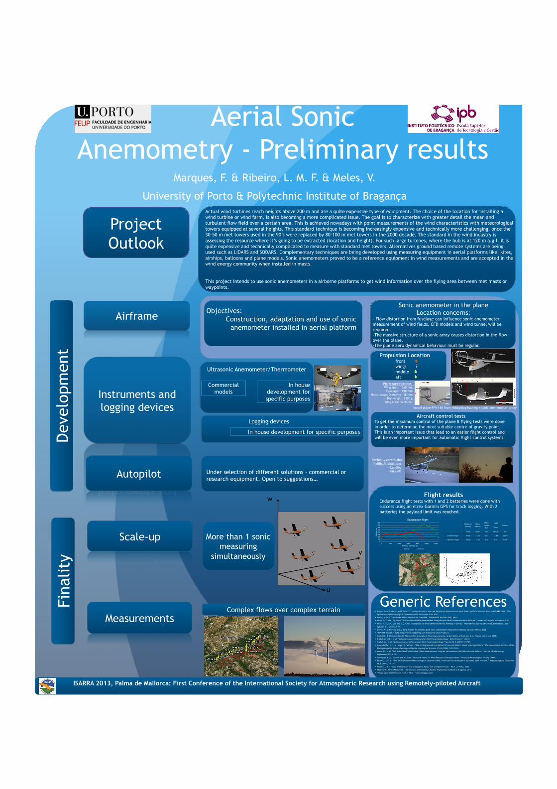
Aerial Sonic Anemometry - Preliminary results
Marques, F. & Ribeiro, L. M. F. & Meles, V.
University of Porto & Polytechnic Institute of Bragança
Airframe
Instruments and logging devices
Scale-up
Measurements
Autopilot
Dev
elop
men
t Fi
nalit
y
Project Outlook
u
v
w
More than 1 sonic measuring
simultaneously
Generic References
Complex flows over complex terrain
Actual wind turbines reach heights above 200 m and are a quite expensive type of equipment. The choice of the location for installing a wind turbine or wind farm, is also becoming a more complicated issue. The goal is to characterize with greater detail the mean and turbulent flow field over a certain area. This is achieved nowadays with point measurements of the wind characteristics with meteorological towers equipped at several heights. This standard technique is becoming increasingly expensive and technically more challenging, once the 30–50 m met towers used in the 90’s were replaced by 80-100 m met towers in the 2000 decade. The standard in the wind industry is assessing the resource where it’s going to be extracted (location and height). For such large turbines, where the hub is at 120 m a.g.l. it is quite expensive and technically complicated to measure with standard met towers. Alternatives ground based remote systems are being used such as LIDARS and SODARS. Complementary techniques are being developed using measuring equipment in aerial platforms like: kites, airships, balloons and plane models. Sonic anemometers proved to be a reference equipment in wind measurements and are accepted in the wind energy community when installed in masts. This project intends to use sonic anemometers in a airborne platforms to get wind information over the flying area between met masts or waypoints.
Ultrasonic Anemometer/Thermometer Commercial
models In house
development for specific purposes
Logging devices In house development for specific purposes
Under selection of different solutions – commercial or research equipment. Open to suggestions…
Objectives: Construction, adaptation and use of sonic
anemometer installed in aerial platform
• Bange, Jens, S. Martin and F. Beyrich. “Comparison of in situ UAV Turbulence Measurements with Tower and Scintillometer Data in LITFASS-2009.” 15th
Symposium on Meteorological Observation and Instrumentation 2010.
• Bento, M. D. F. “Unmanned Aerial Vehicles: An Overview.” InsideGNSS Jan/Feb 2008: 54-61.
• Chao, H. Y. and Y. Q. Chen. “Surface Wind Profile Measurement Using Multiple Small Unmanned Aerial Vehicles.” American Control Conference. 2010.
• Chao, H. Y., Y. C. Cao and Y. Q. Chen. “Autopilots for Small Unmanned Aerial Vehicles: A Survey.” International Journal of Control, Automation, and
Systems 8(1) (n.d.): 36-44.
• Cueva, A., J. Navarro and A. Sanz-Andrés. On multiple-path sonic anemometer measurement theory. Springer-Verlag, 2003.
• “FPV 168 Aircraft.” 2012. http://www.hobbyking.com/hobbyking/store/index.rc.
• Garibaldi, O. Unmanned Aerial Platform For Atmospheric Flux Measurements. United States of America: M.Sc. Purdue University, 2009.
• Giebel, G. (ed.), et al. “Autonomous Aerial Sensors for Wind Power Meteorology - A Pre-Project.” (2012).
• Giebel, G., et al. “Autonomous Aerial Sensors for Wind Power Meteorology.” System 32.2 (2009): 573-585.
• Grenzdörffer, G. J., A. Engel, B. Teichert. “The photogrammetric potential of low-cost UAVs in forestry and agriculture.” The International Archives of the
Photogrammetry, Remote Sensing and Spatial Information Sciences 31.B3 (2008): 1207-1214.
• Kocer, G., et al. “Full-Scale Wind Turbine Near-Wake Measurements Using an Instrumented Uninhabited Aerial Vehicle.” Journal of solar energy
engineering 133.4 (2011).
• Lundquist, K., S. Schreck and W. Shaw. “Research Needs for Wind Resource Characterization.” American Meterological Society (2009).
• Reuder, J., et al. “The Small Unmanned Meteorological Observer SUMO: A new tool for atmospheric boundary layer research.” Meteorologische Zeitschrift
18.2 (2009): 141-147.
• Ribeiro, L.M.F. “Sonic Anemometer and Atmospheric Flows over Complex Terrain.” Ph.d. U. Porto, 2004.
• Steinvorth, Harold Steinvorth. “Aerial Sonic Anemometry.” Master. Polytechnic Institute of Bragança, 2012.
• “Young sonic anemometers.” 2012. http://www.youngusa.com.
Sonic anemometer in the plane Location concerns:
- Flow distortion from fuselage can influence sonic anemometer measurement of wind fields. CFD models and wind tunnel will be required. - The massive structure of a sonic array causes distortion in the flow over the plane. - The plane aero dynamical behaviour must be regular.
Propulsion Location front D wings ? middle C aft C
Flying plan
Aircraft control tests To get the maximum control of the plane 8 flying tests were done in order to determine the most suitable centre of gravity point. This is an important issue that lead to an easier flight control and will be even more important for automatic flight control systems.
Perfectly controlable in dificult situations:
- Landing; -Take off.
Maximum Velocity
Mean Velocity
Mean Sample Rate
Flight
Time Distance
(m/s) (m/s) (Hz) (min:s) (m)
1 BaAery Flight 27,18 17,66 0,41 11:48 12663
2 BaAeries Flight 23,56 15,80 0,39 9:38 9209 0
50
100
150
200
250
300
350
400
0 2000 4000 6000 8000 10000 12000
Alt
itud
e (m
)
Distance travelled (m)
Endurance flight
1 Battery 2 Batteries
Model plane FPV-168 from Hobbyking hauling a sonic anemometer proxy
Flight results Endurance flight tests with 1 and 2 batteries were done with success using an etrex Garmin GPS for track logging. With 2 batteries the payload limit was reached.
Plane specifications: Wing Span: 1660 mm
Fuselage: 1190 mm Motor Mount Diameter: 58 mm
Dry weight: 1300 g Wing Area: 3210 cm2
ISARRA 2013, Palma de Mallorca: First Conference of the International Society for Atmospheric Research using Remotely-piloted Aircraft