laser-induced forward transfer of functional materials ... · jlmn-journal of laser micro ......
TRANSCRIPT
JLMN-Journal of Laser Micro/Nanoengineering Vol. 9, No. 3, 2014
192
Laser-Induced Forward Transfer of Functional Materials: Advances and Future Directions
Alberto Piqué and Heungsoo Kim
Materials Science & Technology Division, Naval Research Laboratory, Washington, DC, USA E-mail: [email protected]
Laser direct-write (LDW) techniques based on laser-induced forward transfer (LIFT) of func-tional materials offer unique advantages and capabilities for the rapid prototyping of electronic, op-tical and sensor elements as opposed to other digital printing processes like inkjet. LIFT processes have been applied to the fabrication of a wide variety of microelectronic elements such as intercon-nects, passive components, antennas, sensors, power sources and embedded circuits. Overall, LDW techniques are highly adaptable digital microfabrication processes in terms of materials versatility, substrate compatibility and range of writing speed, scale and resolution. This article will describe the unique advantages and capabilities of LIFT-based processes when used in conjunction with flu-ids and nanopastes, discuss their applications and consider their future for printing electronics.
Keywords: laser induced forward transfer, LIFT, laser direct-write, laser printing, printed electron-ics, nanoinks
1. Introduction Direct-write processes are evolving into viable tech-
niques for printing functional materials over diverse types of surfaces for the digital fabrication of microelectronic devices. These simple, relatively fast, low cost and envi-ronmentally friendly alternatives to traditional photolitho-graphic processes have the potential of completely chang-ing the way microelectronics are presently fabricated. The use of laser direct-write techniques based on the laser-induced forward transfer, or LIFT process has grown sig-nificantly since the first reports of patterned copper deposi-tion with LIFT made by Bohandy and coworkers over 25 years ago [1].
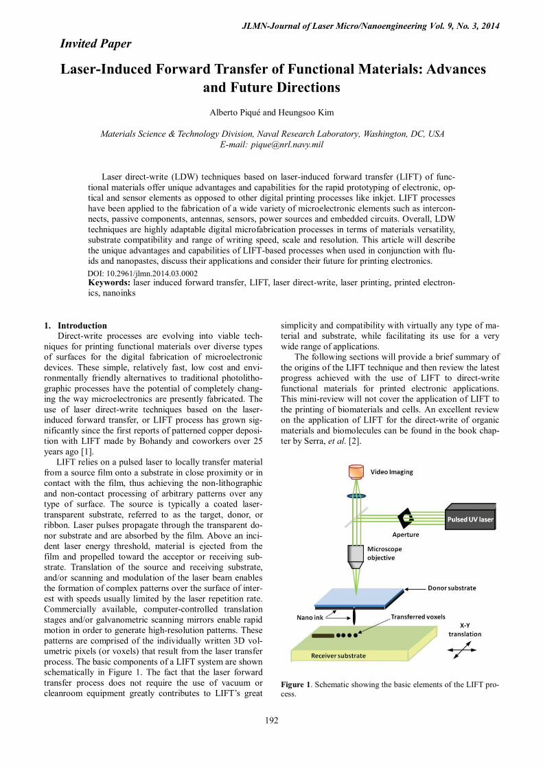
LIFT relies on a pulsed laser to locally transfer material from a source film onto a substrate in close proximity or in contact with the film, thus achieving the non-lithographic and non-contact processing of arbitrary patterns over any type of surface. The source is typically a coated laser-transparent substrate, referred to as the target, donor, or ribbon. Laser pulses propagate through the transparent do-nor substrate and are absorbed by the film. Above an inci-dent laser energy threshold, material is ejected from the film and propelled toward the acceptor or receiving sub-strate. Translation of the source and receiving substrate, and/or scanning and modulation of the laser beam enables the formation of complex patterns over the surface of inter-est with speeds usually limited by the laser repetition rate. Commercially available, computer-controlled translation stages and/or galvanometric scanning mirrors enable rapid motion in order to generate high-resolution patterns. These patterns are comprised of the individually written 3D vol-umetric pixels (or voxels) that result from the laser transfer process. The basic components of a LIFT system are shown schematically in Figure 1. The fact that the laser forward transfer process does not require the use of vacuum or cleanroom equipment greatly contributes to LIFT’s great
simplicity and compatibility with virtually any type of ma-terial and substrate, while facilitating its use for a very wide range of applications.
The following sections will provide a brief summary of the origins of the LIFT technique and then review the latest progress achieved with the use of LIFT to direct-write functional materials for printed electronic applications. This mini-review will not cover the application of LIFT to the printing of biomaterials and cells. An excellent review on the application of LIFT for the direct-write of organic materials and biomolecules can be found in the book chap-ter by Serra, et al. [2].
Figure 1. Schematic showing the basic elements of the LIFT pro-cess.
Invited Paper
DOI: 10.2961/jlmn.2014.03.0002

JLMN-Journal of Laser Micro/Nanoengineering Vol. 9, No. 3, 2014
193
2. Origin of the LIFT Technique The earliest report of laser-induced forward transfer of
material across an air gap can be found in the work per-formed by Levene et al. back in 1970 [3]. The material transferred consisted of black ink from a polyethylene backed typewriter ribbon and colored dies from a Mylar substrate across gaps up to 100 μm wide using a Nd:YAG laser (λ = 1.06 μm). Although the authors motivation was to develop a laser-based printing or marking process (the authors referred to it as recording), their work was presci-ent in highlighting the simplicity and high writing speed of the technique, while proposing a simple model based on the melting and vaporization of the transferred material as a function of the laser pulse energy. Unfortunately the au-thors did not apply their technique to any other types of materials and their work went unnoticed until the late 1990’s when their article began being cited within the printing and image science community.
Fifteen years later, the laser-induced forward transfer process was rediscovered, this time with metals. In 1986 Bohandy, et al. reported the deposition of copper metal patterns via laser forward transfer inside a vacuum chamber [1]. Excimer laser pulses (λ = 193 nm, 15 ns) were focused with a cylindrical lens to a 25 mm long by 50 μm wide line on a donor substrate containing a thin copper film. The Cu was transferred to silicon and fused silica substrates, where further examination revealed resistivities ranging between 3 to 50 times the value for bulk copper and adhesion that survived the tape test.
Bohandy’s group coined the term laser-induced forward transfer (LIFT) to denote the process and proposed a model more detailed but similar to Levene’s to describe the pro-cess. According to this model; (1) the laser pulse heats the interface of the film at the donor substrate; (2) a resulting melt front propagates through the film until it reaches the free surface; (3) at about this time, the material at the inter-face is superheated beyond its boiling point until, (4) the resulting vapor induced pressure at the interface propels the molten film forward towards the acceptor substrate [4]. The same group then demonstrated that this process could be carried out in air, i.e. under atmospheric conditions, with-out the need for a vacuum [5]. Since then, the LIFT tech-nique has been applied to the transfer of numerous types of materials. For more information on the application of LIFT with metals, ceramics and other material systems, the read-er should consult several previously published reviews such as the one by Arnold, el al. [6] and the one by Piqué, et al. [7].
3. Evolution of LIFT
Traditional LIFT processes rely in the melting and, de-pending on the laser pulse energy, vaporization of the mate-rial being transferred. As the transferred voxel material undergoes melting and solidification during LIFT, the for-mation of interfaces between adjacent voxels cannot be avoided leading to degradation of the electrical, thermal and mechanical properties of the printed structures. As a result, several variations of the LIFT process were devel-oped to reduce or eliminate excessive heating of the mate-rial undergoing transfer, thus avoiding their degradation and loss of functionality. The two most successful LIFT
variants are (1) LIFT using a susceptor sacrificial layer and (2) LIFT of fluids or suspensions.
LIFT with a susceptor film, known as a dynamic re-lease layer or DRL was first reported by Tolbert, et al. in 1993 [8]. Early applications were directed towards the transfer of non-laser absorbing materials and relied on me-tallic DRLs. Later on, polymer DRLs that readily vaporize at lower laser ablation thresholds were demonstrated, sig-nificantly minimizing heating of the transferred material [9].
The second LIFT variant relies on the interaction of the laser pulse with fluids in the donor substrate, rather than solids. In this case, the transfer takes place directly from a liquid donor film, whereby the laser pulse, absorbed at the solid-liquid interface, vaporizes a small fraction of the fluid resulting in the formation of a high-pressure bubble whose expansion propels the remaining fluid away from the donor substrate. The fluid in question might be a simple liquid or a more complex rheological system with solids suspended in a solvent, such as ink [10]. In the case of inks, the mate-rial to be transferred moves with the propelled fluid and ultimately reaches the receiving substrate. There it forms a voxel, in a process very similar to inkjet printing. A sche-matic of the steps leading to LIFT of liquid films is provid-ed in Figure 2.
Figure 2. Schematic representation of the steps involved in LIFT of liquid films. (i) The laser pulse is absorbed at the ribbon/fluid interface. (ii) The absorption of the laser pulse heats the solvent forming a bubble. (iii) A droplet or voxel of fluid is ejected away from the donor substrate towards the receiving substrate. (iv) The ejected material is collected on the receiving substrate.
The uniqueness of the laser transfer of rheological sys-tems resides in the fact that it represents a totally new ap-proach to LIFT based on the non-phase transforming for-ward transfer of complex suspensions, inks or pastes. This is made possible by the reduced shear forces required to dislodge and release the portion of the coating in the donor substrate illuminated by the laser pulse. As result, transfers
JLMN-Journal of Laser Micro/Nanoengineering Vol. 9, No. 3, 2014
194
can take place at lower laser fluences, thus eliminating any laser-induced damage to the transferred material. Given the diverse nature and large number of parameters affecting the laser transfer process for rheological systems, a simple schematic as the one provided in Figure 2 does not entirely describe the behavior of LIFT with fluids. However, under most conditions, this simple inkjet-like jetting transfer is what is observed. Numerous studies of LIFT of liquids and inks with and without the use of DRLs, have been conduct-ed by several groups, and while is not possible to list them all in this short review, the reader is directed to the works by the groups at the University of Barcelona [11], and at Princeton University [12] for more details.
In general, the dimensions of the jetted droplets can be varied by adjusting the laser pulse energy density or flu-ence. Below a certain fluence threshold, no transfer takes place. Once the fluence transfer threshold is reached, well-defined spherical droplets are formed as they travel away from the donor substrate. If the fluence is increased further, irregular droplets are generated and droplet variation from one laser pulse to the next leads to irregular voxels and satellite droplets. To obtain good control on the size of transferred voxels, both the laser pulse energy and the laser beam spot dimensions must be optimized first. Once opti-mized though, LIFT of fluids can operate with a wide range of solutions and suspensions no matter what their chemistry or viscosity is, and its voxel resolution can be adjusted within a range of tens of microns. Such features are not possible with inkjet, where the nozzle fixes the voxel size and severely limits, due to clogging, the viscosity and chemical reactivity of the fluids that can be printed.
4. Industrial applications of LIFT
In order to implement LIFT processes in large-scale in-dustrial applications, such as roll-to-roll (R2R) printing, very high writing speeds (in excess of m/s) must be achieved. Furthermore, uniform voxel size must be main-tained during transfers, combined with precise voxel placement onto the receiving substrate. To this end, DI Pro-jekt AG, in conjunction with Aurentum GmbH, has devel-oped the Lasersonic® technique to demonstrate record high writing speeds with LIFT. The name Lasersonic® is a reg-istered trademark of Aurentum GmbH, Germany.
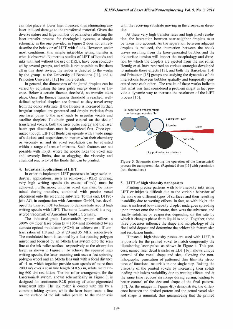
The industrial-grade Lasersonic® system utilizes a 300W cw fiber laser beam (λ = 1064 nm) modulated by an acousto-optical modulator (AOM) to achieve on-off con-trast ratios of 1:8 and 1:5 at 20 and 35 MHz, respectively The modulated beam is scanned by a fast rotating polygon mirror and focused by an f-theta lens system onto the scan line at the ink roller surface, respectively at the absorption layer, as shown in Figure 3. To achieve the required high writing speeds, the laser scanning unit uses a fast spinning polygon wheel and an f-theta lens unit with a focal distance of ~1 m, which together provide scan speeds of more than 2000 m/s over a scan line length of 0.53 m, while maintain-ing 600 dpi resolution. The ink roller arrangement for the Lasersonic® system, shown schematically in Figure 3, is designed for continuous R2R printing of color pigmented transparent inks. The ink roller is coated with ink by a common inking system, while the laser beam scans a line on the surface of the ink roller parallel to the roller axis
with the receiving substrate moving in the cross-scan direc-tion.
At these very high transfer rates and high pixel resolu-tion, the interaction between near-neighbor droplets must be taken into account. As the separation between adjacent droplets is reduced, the interaction between the shock waves resulting from the laser-generated bubbles and the ink surface tension will impact the morphology and direc-tion by which the droplets are ejected from the ink roller. Hennig et al. have reported on various strategies developed to mitigate these effects [13], and both the Barcelona [14] and Princeton [15] groups are studying the dynamics of the interactions between bubbles spatially and temporally gen-erated near each other. The results of these works indicate that what was first considered a problem might in fact pro-vide a dynamic way to increase the resolution of the LIFT process [15].
Figure 3. Schematic showing the operation of the Lasersonic® process for transparent inks. (Reprinted from [13] with permission from the authors.)
5. LIFT of high viscosity nanopastes Printing precise patterns with low-viscosity inks using
LIFT or inkjet is difficult due to the variable behavior of the inks over different types of surfaces and their resulting instability due to wetting effects. In fact, as with inkjet, the laser transferred low-viscosity droplet undergoes spreading upon impact onto the substrate, then wets the substrate, and finally solidifies or evaporates depending on the rate by which it changes phase from liquid to solid. Together, these three processes influence the shape and morphology of the final solid deposit and determine the achievable feature size and resolution limits.
If instead, high-viscosity pastes are used with LIFT, it is possible for the printed voxel to match congruently the illuminating laser pulse, as shown in Figure 4. This pro-cess, named laser decal transfer or LDT [16], allows unique control of the voxel shape and size, allowing the non-lithographic generation of patterned thin film-like struc-tures of functional materials in one single step. Raising the viscosity of the printed voxels by increasing their solids loading minimizes variability due to wetting effects and at the same time reduces shrinkage during curing, leading to better control of the size and shape of the final patterns [17]. As the images in Figure 4(b) demonstrate, the differ-ence between the desired pattern and the actual voxel size and shape is minimal, thus guaranteeing that the printed
JLMN-Journal of Laser Micro/Nanoengineering Vol. 9, No. 3, 2014
195
structures will match the design. This is in fact one of the great attributes of the LDT process.
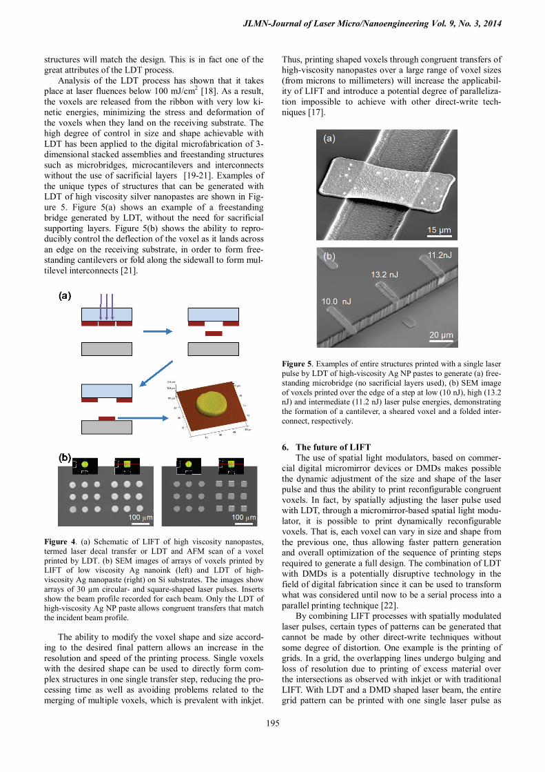
Analysis of the LDT process has shown that it takes place at laser fluences below 100 mJ/cm2 [18]. As a result, the voxels are released from the ribbon with very low ki-netic energies, minimizing the stress and deformation of the voxels when they land on the receiving substrate. The high degree of control in size and shape achievable with LDT has been applied to the digital microfabrication of 3-dimensional stacked assemblies and freestanding structures such as microbridges, microcantilevers and interconnects without the use of sacrificial layers [19-21]. Examples of the unique types of structures that can be generated with LDT of high viscosity silver nanopastes are shown in Fig-ure 5. Figure 5(a) shows an example of a freestanding bridge generated by LDT, without the need for sacrificial supporting layers. Figure 5(b) shows the ability to repro-ducibly control the deflection of the voxel as it lands across an edge on the receiving substrate, in order to form free-standing cantilevers or fold along the sidewall to form mul-tilevel interconnects [21].
Figure 4. (a) Schematic of LIFT of high viscosity nanopastes, termed laser decal transfer or LDT and AFM scan of a voxel printed by LDT. (b) SEM images of arrays of voxels printed by LIFT of low viscosity Ag nanoink (left) and LDT of high-viscosity Ag nanopaste (right) on Si substrates. The images show arrays of 30 µm circular- and square-shaped laser pulses. Inserts show the beam profile recorded for each beam. Only the LDT of high-viscosity Ag NP paste allows congruent transfers that match the incident beam profile.
The ability to modify the voxel shape and size accord-
ing to the desired final pattern allows an increase in the resolution and speed of the printing process. Single voxels with the desired shape can be used to directly form com-plex structures in one single transfer step, reducing the pro-cessing time as well as avoiding problems related to the merging of multiple voxels, which is prevalent with inkjet.
Thus, printing shaped voxels through congruent transfers of high-viscosity nanopastes over a large range of voxel sizes (from microns to millimeters) will increase the applicabil-ity of LIFT and introduce a potential degree of paralleliza-tion impossible to achieve with other direct-write tech-niques [17].
Figure 5. Examples of entire structures printed with a single laser pulse by LDT of high-viscosity Ag NP pastes to generate (a) free-standing microbridge (no sacrificial layers used), (b) SEM image of voxels printed over the edge of a step at low (10 nJ), high (13.2 nJ) and intermediate (11.2 nJ) laser pulse energies, demonstrating the formation of a cantilever, a sheared voxel and a folded inter-connect, respectively.
6. The future of LIFT The use of spatial light modulators, based on commer-
cial digital micromirror devices or DMDs makes possible the dynamic adjustment of the size and shape of the laser pulse and thus the ability to print reconfigurable congruent voxels. In fact, by spatially adjusting the laser pulse used with LDT, through a micromirror-based spatial light modu-lator, it is possible to print dynamically reconfigurable voxels. That is, each voxel can vary in size and shape from the previous one, thus allowing faster pattern generation and overall optimization of the sequence of printing steps required to generate a full design. The combination of LDT with DMDs is a potentially disruptive technology in the field of digital fabrication since it can be used to transform what was considered until now to be a serial process into a parallel printing technique [22].
By combining LIFT processes with spatially modulated laser pulses, certain types of patterns can be generated that cannot be made by other direct-write techniques without some degree of distortion. One example is the printing of grids. In a grid, the overlapping lines undergo bulging and loss of resolution due to printing of excess material over the intersections as observed with inkjet or with traditional LIFT. With LDT and a DMD shaped laser beam, the entire grid pattern can be printed with one single laser pulse as

JLMN-Journal of Laser Micro/Nanoengineering Vol. 9, No. 3, 2014
196
shown in Figure 6(a). With the DMD the laser pulse is spa-tially configured to form the grid while the congruent na-ture of the voxels generated by LDT guarantees that the shape and pattern of the laser pulse is not lost. Furthermore, as long as the energy distribution across the laser spot is uniform and over the transfer threshold, LDT can be used to print voxels of arbitrarily large area. This is shown in the pattern in Figure 6(b), which extends over 1 mm in one direction with the NRL oval seal generated by the DMD image and printed with a single laser pulse. Note that a printed linewidth of < 25 µm can be maintained over a 1 mm2 area. This pattern, which represents a variation in printed area of over 3 orders of magnitude from the ≈ 1x103 mm2 square voxels shown in Figure 4(b), illustrates the large dynamic range in printable area achievable with LDT. From an applications perspective, these congruent LDT examples combined with the high writing speeds achievable with the Lasersonic® process illustrate the fu-ture applications for LIFT in printed electronics, device interconnects, and circuit repairs, all of which become highly relevant when combined with the printing of a wide range of functional inks and pastes.
Figure 6. Examples of full patterns printed with a single laser pulse by LDT of high-viscosity Ag NP pastes with the laser pulse spatially shaped by a digital micromirror device (DMD). (a) Ex-ample of a square grid generated by the DMD. Note the sharp corner features and fine lines. (b) Arbitrary pattern over large area (NRL logo is over 1 mm long) with high feature resolution.
7. Summary LIFT techniques are ideally suited for digital microfab-
rication applications and offer opportunities for the genera-tion of patterns, structures and devices not possible with traditional photolithographic tools. Because they are non-lithographic digital microfabrication processes, laser-induced forward transfer techniques can be used for nu-merous rapid prototyping applications, allowing the design, fabrication and testing of a given structure to be completed in a very short time. Examples of where the LIFT tech-
nique might lead in the future are demonstrated by the re-cent work demonstrating LIFT at very high writing speeds for R2R applications and by the development of congruent laser printing with reconfigurable voxels by combining laser decal transfer with digital micromirror devices. Acknowledgments
This work was funded by the Office of Naval Research (ONR) through the Naval Research Laboratory Basic Re-search Program. The authors would like to thank Dr. Guido Hennig of DI Projekt AG, for providing valuable details on the Lasersonic® process.
References [1] J. Bohandy, B. Kim, F.J. Adrian: J. Appl. Phys. 60,
(1986) 15386. [2] P. Serra, M. Duocastella, J.M. Fernández-Pradas, J.L.
Morenza: “Laser-Induced Forward Transfer: A Laser-Based Technique for Biomolecules Printing” in Cell and Organ Printing, ed. by B.R. Ringeisen, B.J. Spargo and P.K. Wu, (Springer, Heidelberg, 2010) p.53.
[3] M.L. Levene, R.D. Scott, B.W. Siryj: Appl. Optics 9, (1970) 2260.
[4] F. J. Adrian, J. Bohandy, B. F. Kim, A. N. Jette, P. Thompson: J. Vac. Sci. and Techno l. B5, (1987) 1490.
[5] J. Bohandy, B. Kim, F. J. Adrian, A. N. Jette: J. Appl. Phys. 63, (1988) 1158.
[6] C. B. Arnold, P. Serra, A. Piqué: MRS Bulletin 32, (2007) 23.
[7] A. Piqué: “Laser Transfer Techniques for Digital Mi-crofabrication” in Laser Precision Microfabrication, ed. by K. Sugioka, M. Meunier and A. Piqué, (Spring-er, Heidelberg, 2010) p.259.
[8] W.A. Tolbert, I.Y.S. Lee, M.M. Doxtader, E.W. Ellis, D.D. Dlott: Journal of Imaging Science and Technolo-gy 37, (1993) 411.
[9] R. Fardel, M. Nagel, F.A. Nüesch, T. Lippert A. Wokaun: Appl. Surf. Sci. 254, (2007) 1322.
[10] A. Piqué, J. Fitz-Gerald, D.B. Chrisey, R.C.Y. Auyeung, H.D. Wu, S. Lakeou, R.A. McGill: Proc. SPIE, 3933, (2000) 105.
[11] M. Colina, M. Duocastella, J. M. Ferna ́ndez-Pradas, P. Serra, J. L. Morenza: J. of Appl. Phys. 99, (2006) 84909.
[12] N. T. Kattamis, P. E. Purnick, R. Weiss, C. B. Arnold: Appl. Phys. Lett. 91, (2007) 171120.
[13] G. Hennig, T. Baldermann, C. Nussbaum, M. Rossier, A. Brockelt, L. Schuler, G. Hochstein: J. Laser Mi-cro/Nanoeng. 7, (2012) 299.
[14] A. Patrascioiu, J.M. Fernández-Pradas, J.L. Morenza, P. Serra: Appl. Surf. Sci. 302 (2014) 303.
[15] C.F. Brasz, J.H. Yang, C.B. Arnold: Proc. LPM2014, paper# Fr1-O-11 (2014) p. 183.
[16] A. Piqué, R. C. Y. Auyeung, H. Kim, K. M. Metkus, S. A. Mathews: J. Laser Micro/Nanoeng 3, (2008) 163.
[17] A. Piqué, H. Kim, R. C .Y. Auyeung, A. Smith: J. Im-aging Sci. Techno. 57, (2013) 040404-1.
[18] S.A. Mathews, R.C.Y. Auyeung, H. Kim, N.A. Cha-ripar, A. Piqué: J. Appl. Phys. 114, (2013) 64910.

JLMN-Journal of Laser Micro/Nanoengineering Vol. 9, No. 3, 2014
197
[19] R.C.Y. Auyeung, H. Kim, A.J. Birnbaum, M. Zalalutdinov, S.A. Mathews, A. Piqué: Appl. Phys. A: Materials Science and Processing 97, (2009) 513.
[20] J. Wang, R.C.Y. Auyeung, H. Kim, N.A. Charipar, A. Piqué: Advanced Materials 22, (2010) 4462.
[21] H. Kim, M. Duocastella, K. M. Charipar, R. C. Y. Auyeung, A. Piqué: Appl. Phys. A: Materials Science and Processing 113, (2013) 5.
[22] A. Piqué, R.C.Y. Auyeung, A.T. Smith, H. Kim, S.A. Mathews, N.A. Charipar, M.A. Kirleis: Proc. SPIE, 8608, (2013) 86080K.
(Received: June 18, 2014, Accepted: September 26, 2014)