laser surveys · sketchup (skp) the functionality of the model will depend on format in which the...
TRANSCRIPT
Laser Surveys BIM ready models
© P a g e | 1
LASER SURVEYS
BIM Ready Models
A guide for our Clients

Laser Surveys BIM ready models
© P a g e | 2
Introduction - the purpose of this guide:
Survey information for the construction industry has a long-established
tradition and is generally well understood by both Clients and Surveyors.
The advent of BIM has led to presenting information in different formats
and this document attempts to clarify what can, and cannot, be delivered.
With an understanding of what is intended to be issued, a Client can adjust
their order to ensure that the model will meet their needs.
The Company: Laser Surveys was established in the Midlands in 1975 with our London office
opening in 1988. We carry out all types of survey work throughout the
mainland UK with our team of over 60 employees.
Our Services: Topographical surveys, building surveys and underground services surveys
are just part of what we do.
We also supply digital datasets and reports, OS mapping, 3D Models, UAV
surveys, historical mapping, geological and borehole information, and we
have been providing BIM ready models since 2015.
Experience: Over forty years of providing surveys using the latest surveying techniques.
BIM Team: We have a team of dedicated Revit modellers in both our London and
Worcester offices, allowing the size of the project team to be expanded to
suit the workload.

Laser Surveys BIM ready models
© P a g e | 3
Essential information for creating a BIM ready model:
To meet our client’s requirements we need to understand the
following:
1. Which “Grade of Detail” of the Revit Model is required for the site,
the building exterior and the building interior.
If you want Phasing applied to the model.
2. If any 2D CAD drawings are also required.
3. If the Point Cloud data is required.
4. If the Survey is to be located on a local Datum and Grid or to the
OS Datum and National Grid coordinate system.
And as a Client you should also be aware of:
5. That the extent of the model is dependent upon the access that
the surveyors are given.
These items are identified on the “Revit Deliverables” part of our order
form where our clients can select options and add comments or specific
requirements.
Each of these items is explained in more detail in the following sections.

Laser Surveys BIM ready models
© P a g e | 4
1a-buildings GRADES OF DETAIL FOR BUILDINGS AND STRUCTURES
Our simplified order form has four “Grades of Detail” for
buildings and structures.
GRADE B4 – High Detail.
Laser Surveys project specific families of doors, windows, stairs, ramps
and balustrades.
Project specific families based upon more detailed dimensions for
fixtures, fittings, materials and architectural features.
GRADE B3 – Standard Detail.
Laser Surveys generic families of doors, windows, stairs, ramps and
balustrades.
Generic families based upon overall dimensions for fixtures, fittings, and
architectural features.
GRADE B2 – Outline Model.
Overall shape of major walls, columns, floors, ceilings and roofs, with
openings.
GRADE B1 – Massing Model.
Overall shape of external building envelope.

Laser Surveys BIM ready models
© P a g e | 5
ITEMS TO CONSIDER FOR GRADES OF DETAIL FOR
BUILDINGS AND STRUCTURES
Different “grades of detail” can be applied to the interior and the exterior,
or to different buildings, or parts of buildings on the site.
For example, on a refurbishment project the model may require a high
grade of detail (B4) for the exterior, which is to be retained, but only an
outline grade (B2) for the interior, which is to be stripped out.
Consideration for grades B2, B3 and B4 should be identified for:
• Walls
• Cornices
• Dados
• Skirtings
• Floors
• Structural Columns and Beams
• Secondary Structural elements
• Ceilings and ceiling features
• Bulkheads
• Roofs, gutters and fascia’s
• Windows and Curtain walling
• Doors and screens
• Stairs and handrailing
• Lifts and escalators
• Fixed furniture and fire surrounds
• Pipework and sanitaryware
• Building services
Please identify on the order form if extra detailing to any of these is
required.
Where no specific requirements are identified for these then Laser Surveys
standard modelling techniques will be used.
A Revit phase of “Existing” can be applied. We do not normally do this
unless a Client requests it. Phasing can make items appear, disappear and
change colour, so unless it is used on a project we do not normally apply it.
Often it is only practical to survey one side of an element (for example a
ceiling) but a thickness is required to create an object in Revit.
Where this is necessary the object properties will be named
“Wall/Floor/Ceiling/Roof of unknown thickness”.
Laser Surveys generic families are created in accordance with NBS BIM
Object Standards in terms of geometry, behaviour and presentation.
Metadata within the Laser Surveys generic families is compliant with the
requirements for generic objects as specified within the BIM Object
Standards.
Clients can thus add in their own metadata, as information becomes
available during the project, and the survey model would comply with the
requirements for a COBie data drop.

Laser Surveys BIM ready models
© P a g e | 6
1b-site GRADES OF DETAIL FOR TOPOGRAPHY
The order form has a further three “Grades of Detail” for Site
Topography.
GRADE S3 – Revit Toposurface with sub-regions and site
features.
Revit “toposurface” based on site level data points, and then divided into
sub-regions to identify surface finishes.
Site features such as steps, street furniture, barriers, retaining walls, and
trees also modelled as Revit objects.
GRADE S2 – Revit Toposurface with sub-regions
Revit “toposurface” based on site level data points, and then divided into
sub-regions to identify surface finishes.
GRADE S1 – Revit Toposurface only
Revit “toposurface” based on site level data points.

Laser Surveys BIM ready models
© P a g e | 7
ITEMS TO CONSIDER FOR GRADES OF DETAIL FOR SITES
AND TOPOGRAPHY
Different grades can be applied to distinct parts of the site, for example
stairs and ramps directly connected to a building may be required.
Revit “toposurfaces” do not happily run vertically or fold back on
themselves. It is often better to split surfaces at the top and bottom of
kerbs.
If this is not done, then Revit tries to join alternate top and bottom points
giving a diamond shape to the edges. Kerbs are not modelled as Revit
objects.
Revit representations of trees and bushes are generic and only represent
the approximate overall position, height and spread. The Point Cloud should
be used as a data source for more exact geometry of such items.
OTHER MODEL OUTPUT FORMATS –
AUTOCAD, IFC, MICROSTATION and SKETCHUP
3D models can by issued in a variety of formats including:
Revit (RVT and RFA)
AutoCAD 3D files (DWG)
IFC files (for use with Vectorworks etc.)
Microstation (DGN)
SketchUp (SKP)
The functionality of the model will depend on format in which the model is
issued.
RIGHTS OF LIGHT SURVEYS
We regularly carry out “Rights of Light” surveys of specialist consultants
where large areas are surveyed, in outline form, with door and window
openings.
These are far more accurate than the off the shelf data that is sometimes
(but should not be) used.
We can also produce this information with “polylines” around all openings
allowing it to be used in the specialist analytical software used by “Rights
of Light” Surveyors.

Laser Surveys BIM ready models
© P a g e | 8
1c-above ground services GRADES OF DETAIL FOR ABOVE GROUND SERVICES
We currently offer only one “grade of detail” for above ground
services.
GRADE A2 – Services geometry modelled
We will only model the overall size (including insulation) and position of
above ground services, which will not contain the intelligent information
usually incorporated into a BIM object.
Support brackets and structures can be modelled, and generic valves and
fittings can be included.

Laser Surveys BIM ready models
© P a g e | 9
1d-below ground services GRADES OF DETAIL FOR BELOW GROUND SERVICS
We offer only one “grade of detail” for below ground services
GRADE B2 – Services geometry modelled
We will only model the approximate overall size and position of below
ground services, which will not contain the intelligent information usually
incorporated into a BIM object.
Models include a “zone of uncertainty” which represents the limitation of
accuracy of the detection equipment. Some assumptions are also made in
order to make Revit objects, such as the thicknesses of buried walls and
slabs.
Not all underground services are detectable from surface scans. Modelling
them in Revit does not improve the accuracy of what was surveyed with
detection equipment.
Where underground services are accessible we do offer a surveying and
scanning service. Our surveyors have confined space training and we can
arrange traffic management and escape teams for such works.

Laser Surveys BIM ready models
© P a g e | 10
2-CAD output IN ADDITION TO THE REVIT MODEL WE CAN ALSO OFFER 2D
CAD DRAWINGS IN DWG & DXF FORMATS
2D CAD 1:100
We can produce traditionally annotated 2D plans, ceiling plans, sections and
elevations from the model for an additional cost. The annotation will
include figured dimensions for ceiling heights, floor levels, window cill and
head heights and door head heights. Beams and ceiling features will be
shown as dotted lines.
A client’s linestyles and layering conventions can also be incorporated.
Unannotated plans, sections and elevations can also be created at no extra
cost.
Laser Surveys BIM ready models
© P a g e | 11
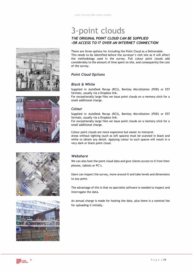
3-point clouds THE ORIGINAL POINT CLOUD CAN BE SUPPLIED
-OR ACCESS TO IT OVER AN INTERNET CONNECTION
There are three options for including the Point Cloud as a Deliverable.
This needs to be identified before the surveyor’s visit site as it will affect
the methodology used in the survey. Full colour point clouds add
considerably to the amount of time spent on site, and consequently the cost
of the survey.
Point Cloud Options
Black & White
Supplied in AutoDesk Recap (RCS), Bentley MicroStation (POD) or E57
formats, usually via a Dropbox link.
For exceptionally large files we issue point clouds on a memory stick for a
small additional charge.
Colour
Supplied in AutoDesk Recap (RCS), Bentley MicroStation (POD) or E57
formats, usually via a Dropbox link.
For exceptionally large files we issue point clouds on a memory stick for a
small additional charge.
Colour point clouds are more expensive but easier to interpret.
Areas without lighting (such as loft spaces) must be scanned in black and
white to obtain any detail. Applying colour to such spaces will result in a
very dark or black point cloud.
Webshare
We can also host the point cloud data and give clients access to it from their
phones, tablets or PC’s.
Users can inspect the survey, move around it and take levels and dimensions
to any point.
The advantage of this is that no specialist software is needed to inspect and
interrogate the data.
An annual charge is made for hosting the data, plus there is a nominal fee
for uploading it initially.

Laser Surveys BIM ready models
© P a g e | 12
4-positioning WHERE COLLABORATION IS IMPORTANT, AS IT IS WITH ALL
BIM PROJECTS, A SHARED SURVEY POINT NEEDS TO BE
AGREED
A Datum, in surveying terms, refers to the vertical height (the z value) of
a point.
A Grid is established in plan view and refers to the vertical and horizontal
positions (x and y values) of a point.
Local Datum and Grid by Surveyor
Our surveyors will establish a local datum and grid point for the survey and
mark it on site and on the survey deliverables.
Construction sites do often damage or obliterate such points, so they should
not be relied upon to be there for the whole duration of the project.
Local Datum and Grid by Client
We can work from a defined point identified by Client, providing this can
be identified to the surveyor upon their first visit to site.
Ordnance Survey Datum and OS Grid.
Many projects use the OS datum and OS Grid coordinates that cover the
whole of the UK.
These are usually annotated as Northings and Eastings for example:
529990E,169990N for gridlines or E384581.299, N255359.262 for individual
points.
Benchmarks are no longer verified or checked by the Ordnance Survey and
are therefore rarely used as they may have moved. We use a satellite system
to establish both Datum and Grid.
Hybrid systems are also available e.g. an OS Datum can be used with a local
Grid. We can accommodate these if we know our Clients requirements
before we commence the survey works.

Laser Surveys BIM ready models
© P a g e | 13
Revit “True North” and “Project North”.
Revit has way of rotating a model without actually rotating it !
It has options for displaying “Project North” and “True North”.
True North in our models will depend upon which “Positioning” option has
been selected earlier in this section, i.e.” Local datum and grid by
surveyor”, “Local datum and grid by client” or “OS datum and OS grid”.
Revit “True North” will align with the survey, which will align with
whichever of those options has been chosen.
Revit “Project North” can apparently rotate the model. This is useful where
buildings are slightly askew, either to the vertical or horizontal planes. It
can be apparently rotated, making drawing new walls much simpler.
Rotating “Project North” does not alter the underlying coordinate system,
which will still read correctly.
It is important to establish this before modelling commences as moving or
rotating a model afterwards, although not impossible, can be problematic.
Please be aware that selecting “True North” in Revit will only orientate
your view to OS North if you have told us that that is the way you wanted
site surveyed, i.e.” OS Datum and OS Grid”.
We include this on our order form and if left unanswered take the view that
Revit “Project North” will be decided by the Surveyor, unless it has
previously agreed with the Client or the Clients Architect.
Using large coordinates
Revit has problems with large coordinate numbers, but our surveys can be
set up to OS Datum and Grid and other Revit files can then simply “Acquire”
the coordinates from our survey.

Laser Surveys BIM ready models
© P a g e | 14
Other Positioning Issues
Repositioning a model after completion can be problematic as the point
cloud and model are set to the same coordinate system before modelling
commences.
Projects are often initiated with an OS Mastermap plan or Title Deed
information from the Land Registry. The latter relies on the former for its
information, and the “absolute accuracy” of an OS Mastermap is:
Scale RMSE* 95%
confidence
level
99%
confidence
level
1:1250 (urban) <±0.5m <±0.8m <±0.9m
1:2500 (rural) (resurvey or reformed) <±1.1m <±1.9m <±2.4m
1:2500 (rural) <±2.8m <±4.7m <±5.8m
1:10 000 (mountain and moorland) <±4.1m <±7.1m <±8.8m
We discuss the accuracy of the survey in our “Client guide to accuracy”
document and generally achieve better than ±25mm. Deed plans and OS
maps are ±800mm in urban areas and ±1900mm in rural areas for a 95%
confidence level.
Hopefully this demonstrates the need for an accurate survey from a
company such as ourselves at as early a stage as possible in the project.
We cannot determine in law a boundary position, but we can accurately
locate certain physical features to enable legal professionals to progress
matters in the appropriate way.

Laser Surveys BIM ready models
© P a g e | 15
5 - access Remember – if you cannot see something from where you
are standing (such as hidden pipework, columns or
beams), it is likely that we cannot survey it.
Survey as found
The standard for most of our surveys.
Areas cleared by client prior to survey.
Existing items are removed and replaced by the client, for example ceiling
tiles, if the structural floor depth needs to be measured.
Specialist access equipment provided by client.
If surveys are needed where safe access is not normally available, for
example lift shafts, then the client may provide safe facilities to allow our
surveyors to carry out their work.
We also publish “BIM Ready Models – Client Guide to Accuracy” should you
wish to know more about the accuracy standards of our models.
If you have any questions or comments about anything in
this document, then please contact us.
This document is copyright of Laser Surveys Ltd. and may not be reproduced in any
form, in part or as a whole, without the written permission of Laser Surveys Ltd.
t: +44 (0)1886833173
Issue B – 16/04/2018