lateral calculations for lines 4 & c riverside #3 4/sta… · lateral calculations for lines 4...
TRANSCRIPT
Lateral Calculations for Lines 4 & C For
Riverside #3 Ada County, Idaho
Prepared by
1102 N Franklin Nampa, Idaho 83687
(208) 475-0040 Fax (208) 475-0044
2015-02595
November 10, 2015
1/12
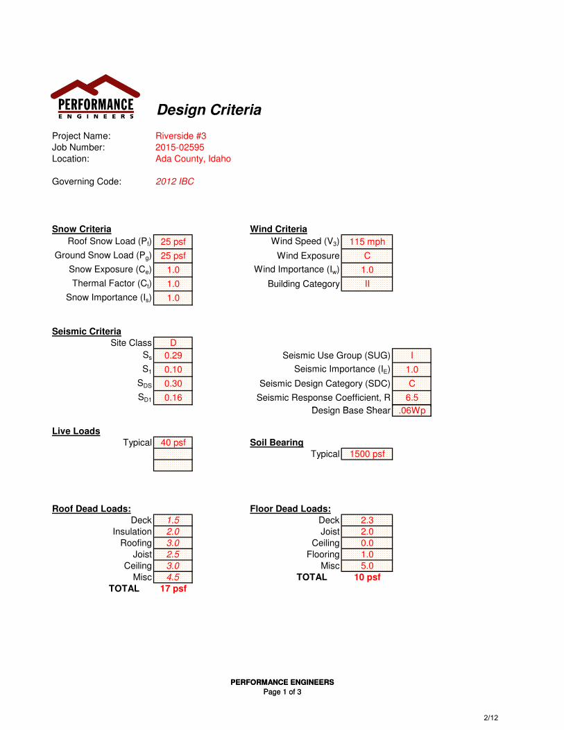
Design Criteria
Project Name: Riverside #3
Job Number: 2015-02595
Location: Ada County, Idaho
Governing Code: 2012 IBC
Snow Criteria Wind Criteria
Roof Snow Load (Pf) 25 psf Wind Speed (V3) 115 mph
Ground Snow Load (Pg) 25 psf Wind Exposure C
Snow Exposure (Ce) 1.0 Wind Importance (Iw) 1.0
Thermal Factor (Ct) 1.0 Building Category II
Snow Importance (Is) 1.0
Seismic Criteria
Site Class D
Ss 0.29 Seismic Use Group (SUG) I
S1 0.10 Seismic Importance (IE) 1.0
SDS 0.30 Seismic Design Category (SDC) C
SD1 0.16 Seismic Response Coefficient, R 6.5
Design Base Shear .06Wp
PERFORMANCE ENGINEERS
Page 1 of 3
Design Base Shear .06Wp
Live Loads
Typical 40 psf Soil Bearing
Typical 1500 psf
Roof Dead Loads: Floor Dead Loads:
Deck 1.5 Deck 2.3
Insulation 2.0 Joist 2.0
Roofing 3.0 Ceiling 0.0
Joist 2.5 Flooring 1.0
Ceiling 3.0 Misc 5.0
Misc 4.5 TOTAL 10 psf
TOTAL 17 psf
PERFORMANCE ENGINEERS
Page 1 of 3 2/12
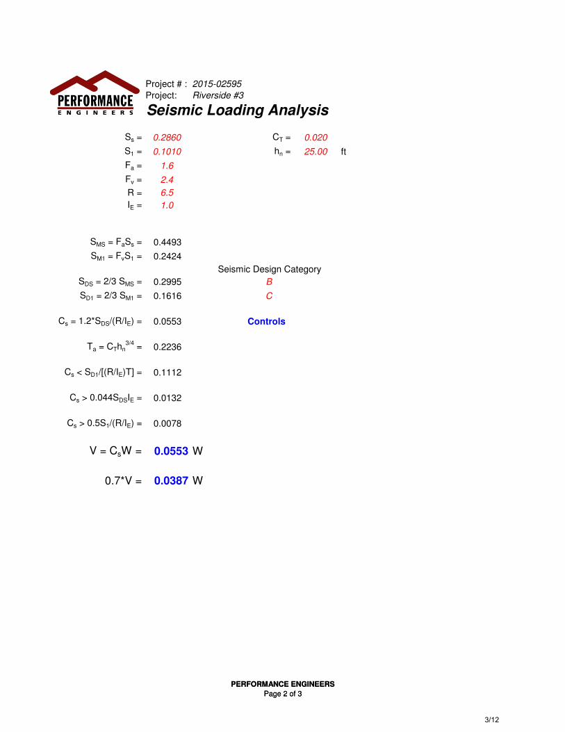
Project # : 2015-02595
Project: Riverside #3
Seismic Loading Analysis
Ss = 0.2860 CT = 0.020
S1 = 0.1010 hn = 25.00 ft
Fa = 1.6
Fv = 2.4
R = 6.5
IE = 1.0
SMS = FaSs = 0.4493
SM1 = FvS1 = 0.2424
Seismic Design Category
SDS = 2/3 SMS = 0.2995 B
SD1 = 2/3 SM1 = 0.1616 C
Cs = 1.2*SDS/(R/IE) = 0.0553 Controls
Ta = CThn3/4
= 0.2236
Cs < SD1/[(R/IE)T] = 0.1112
Cs > 0.044SDSIE = 0.0132
PERFORMANCE ENGINEERS
Page 2 of 3
Cs > 0.5S1/(R/IE) = 0.0078
V = CsW = 0.0553 W
0.7*V = 0.0387 W
PERFORMANCE ENGINEERS
Page 2 of 3 3/12
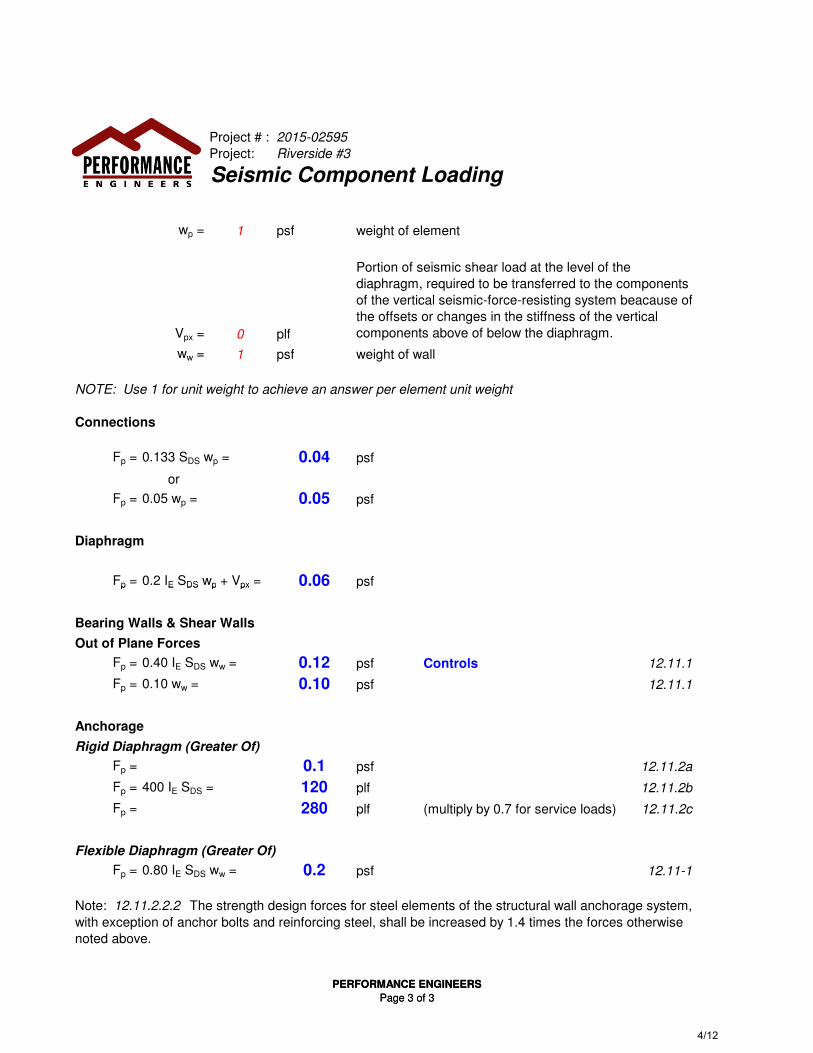
Project # : 2015-02595
Project: Riverside #3
Seismic Component Loading
wp = 1 psf weight of element
Vpx = 0 plf
ww = 1 psf weight of wall
NOTE: Use 1 for unit weight to achieve an answer per element unit weight
Connections
Fp = 0.133 SDS wp = 0.04 psf
or
Fp = 0.05 wp = 0.05 psf
Diaphragm
Fp = 0.2 IE SDS wp + Vpx = 0.06 psf
Portion of seismic shear load at the level of the
diaphragm, required to be transferred to the components
of the vertical seismic-force-resisting system beacause of
the offsets or changes in the stiffness of the vertical
components above of below the diaphragm.
PERFORMANCE ENGINEERS
Page 3 of 3
Fp = 0.2 IE SDS wp + Vpx = 0.06 psf
Bearing Walls & Shear Walls
Out of Plane Forces
Fp = 0.40 IE SDS ww = 0.12 psf Controls 12.11.1
Fp = 0.10 ww = 0.10 psf 12.11.1
Anchorage
Rigid Diaphragm (Greater Of)
Fp = 0.1 psf 12.11.2a
Fp = 400 IE SDS = 120 plf 12.11.2b
Fp = 280 plf (multiply by 0.7 for service loads) 12.11.2c
Flexible Diaphragm (Greater Of)
Fp = 0.80 IE SDS ww = 0.2 psf 12.11-1
Note: 12.11.2.2.2 The strength design forces for steel elements of the structural wall anchorage system,
with exception of anchor bolts and reinforcing steel, shall be increased by 1.4 times the forces otherwise
noted above.
PERFORMANCE ENGINEERS
Page 3 of 3 4/12
"ASCE710W.xls" ProgramVersion 1.0
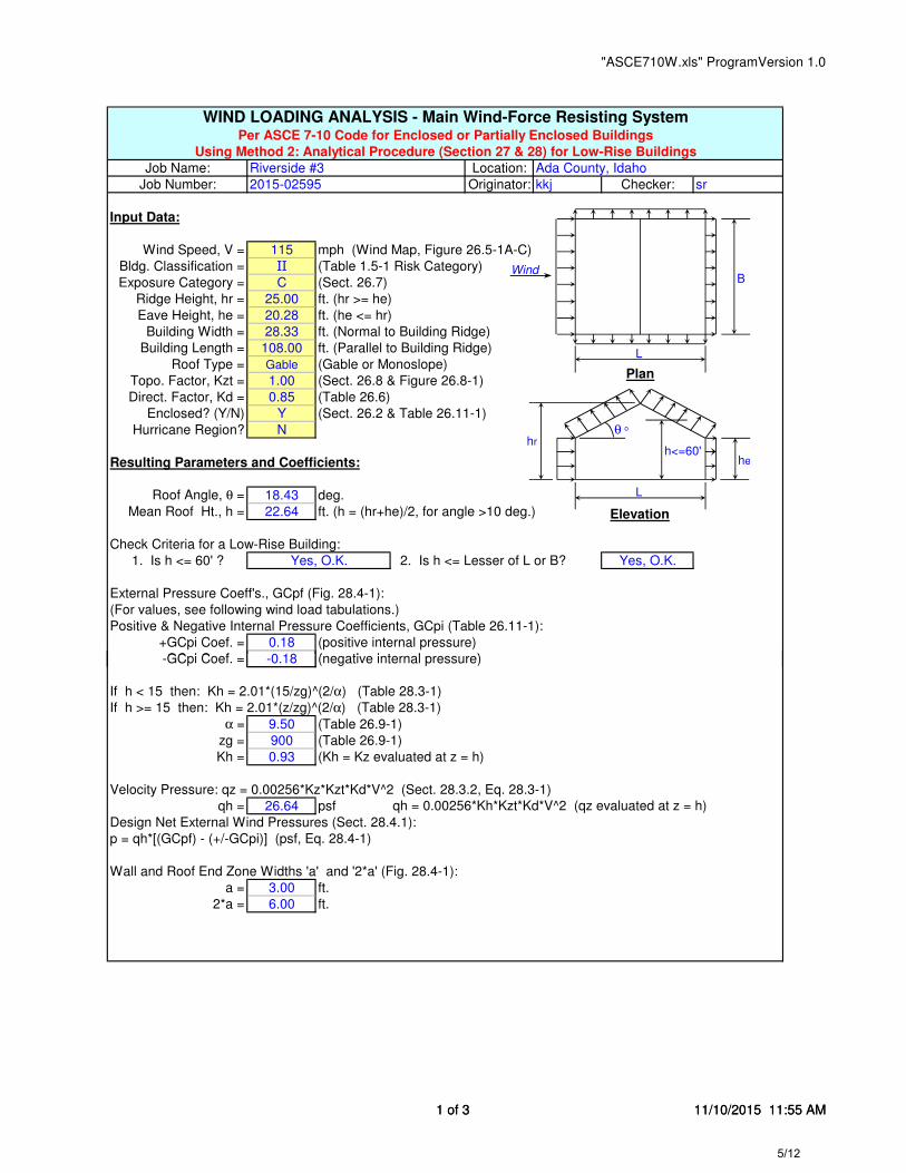
WIND LOADING ANALYSIS - Main Wind-Force Resisting SystemPer ASCE 7-10 Code for Enclosed or Partially Enclosed Buildings
Using Method 2: Analytical Procedure (Section 27 & 28) for Low-Rise Buildings
Job Name: Riverside #3 Location: Ada County, Idaho
Job Number: 2015-02595 Originator: kkj Checker: sr
Input Data:
Wind Speed, V = 115 mph (Wind Map, Figure 26.5-1A-C)
Bldg. Classification = II (Table 1.5-1 Risk Category)
Exposure Category = C (Sect. 26.7)
Ridge Height, hr = 25.00 ft. (hr >= he)
Eave Height, he = 20.28 ft. (he <= hr)
Building Width = 28.33 ft. (Normal to Building Ridge)
Building Length = 108.00 ft. (Parallel to Building Ridge)
Roof Type = Gable (Gable or Monoslope)
Topo. Factor, Kzt = 1.00 (Sect. 26.8 & Figure 26.8-1)
Direct. Factor, Kd = 0.85 (Table 26.6)
Enclosed? (Y/N) Y (Sect. 26.2 & Table 26.11-1)
Hurricane Region? N
Resulting Parameters and Coefficients:
Roof Angle, θ = 18.43 deg.
Mean Roof Ht., h = 22.64 ft. (h = (hr+he)/2, for angle >10 deg.)
Check Criteria for a Low-Rise Building:
1. Is h <= 60' ? Yes, O.K. 2. Is h <= Lesser of L or B? Yes, O.K.
External Pressure Coeff's., GCpf (Fig. 28.4-1):
(For values, see following wind load tabulations.)
Positive & Negative Internal Pressure Coefficients, GCpi (Table 26.11-1):
+GCpi Coef. = 0.18 (positive internal pressure)
-GCpi Coef. = -0.18 (negative internal pressure)
θ o
L
B
hr
heh<=60'
Wind
Plan
Elevation
L
1 of 3 11/10/2015 11:55 AM
-GCpi Coef. = -0.18 (negative internal pressure)
If h < 15 then: Kh = 2.01*(15/zg)^(2/α) (Table 28.3-1)
If h >= 15 then: Kh = 2.01*(z/zg)^(2/α) (Table 28.3-1)
α = 9.50 (Table 26.9-1)
zg = 900 (Table 26.9-1)
Kh = 0.93 (Kh = Kz evaluated at z = h)
Velocity Pressure: qz = 0.00256*Kz*Kzt*Kd*V^2 (Sect. 28.3.2, Eq. 28.3-1)
qh = 26.64 psf qh = 0.00256*Kh*Kzt*Kd*V^2 (qz evaluated at z = h)
Design Net External Wind Pressures (Sect. 28.4.1):
p = qh*[(GCpf) - (+/-GCpi)] (psf, Eq. 28.4-1)
Wall and Roof End Zone Widths 'a' and '2*a' (Fig. 28.4-1):
a = 3.00 ft.
2*a = 6.00 ft.
1 of 3 11/10/2015 11:55 AM 5/12
"ASCE710W.xls" ProgramVersion 1.0
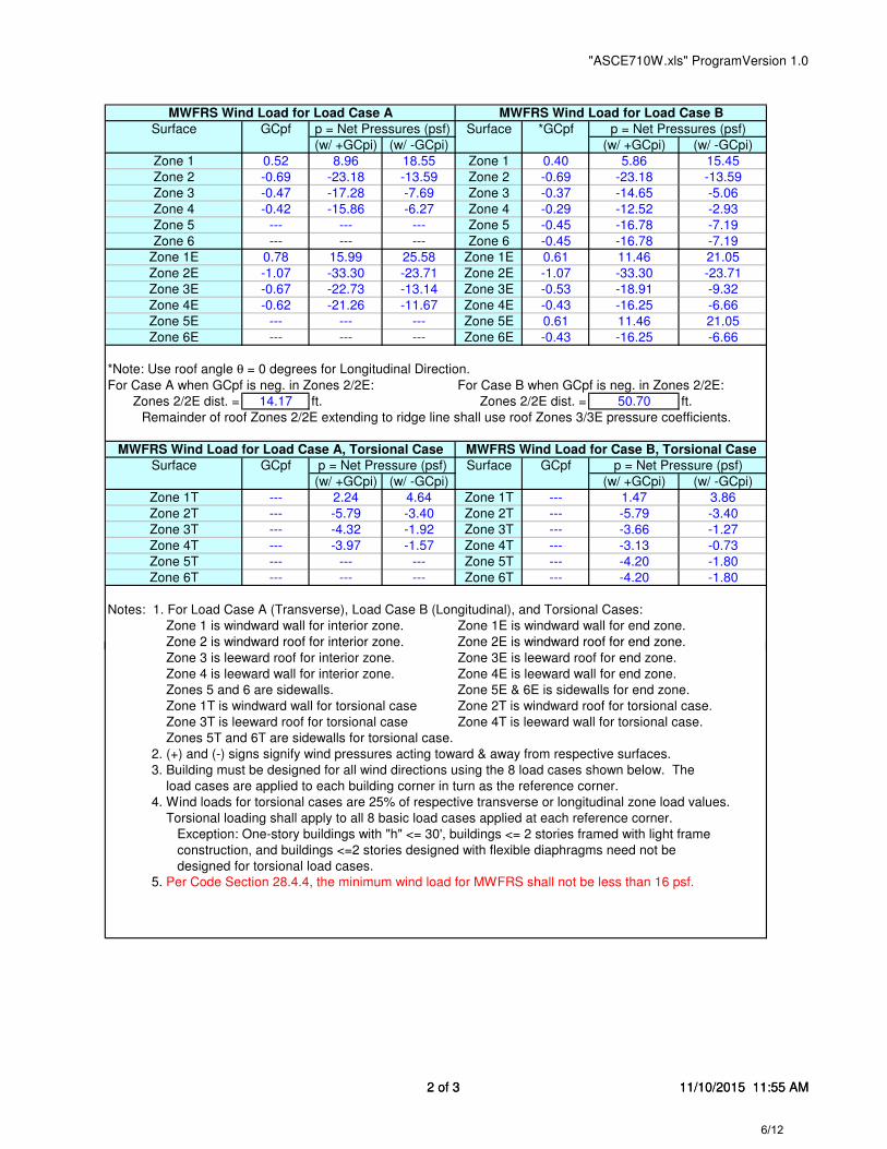
MWFRS Wind Load for Load Case A MWFRS Wind Load for Load Case B
Surface GCpf p = Net Pressures (psf) Surface *GCpf p = Net Pressures (psf)
(w/ +GCpi) (w/ -GCpi) (w/ +GCpi) (w/ -GCpi)
Zone 1 0.52 8.96 18.55 Zone 1 0.40 5.86 15.45
Zone 2 -0.69 -23.18 -13.59 Zone 2 -0.69 -23.18 -13.59
Zone 3 -0.47 -17.28 -7.69 Zone 3 -0.37 -14.65 -5.06
Zone 4 -0.42 -15.86 -6.27 Zone 4 -0.29 -12.52 -2.93
Zone 5 --- --- --- Zone 5 -0.45 -16.78 -7.19
Zone 6 --- --- --- Zone 6 -0.45 -16.78 -7.19
Zone 1E 0.78 15.99 25.58 Zone 1E 0.61 11.46 21.05
Zone 2E -1.07 -33.30 -23.71 Zone 2E -1.07 -33.30 -23.71
Zone 3E -0.67 -22.73 -13.14 Zone 3E -0.53 -18.91 -9.32
Zone 4E -0.62 -21.26 -11.67 Zone 4E -0.43 -16.25 -6.66
Zone 5E --- --- --- Zone 5E 0.61 11.46 21.05
Zone 6E --- --- --- Zone 6E -0.43 -16.25 -6.66
*Note: Use roof angle θ = 0 degrees for Longitudinal Direction.
For Case A when GCpf is neg. in Zones 2/2E: For Case B when GCpf is neg. in Zones 2/2E:
Zones 2/2E dist. = 14.17 ft. Zones 2/2E dist. = 50.70 ft.
Remainder of roof Zones 2/2E extending to ridge line shall use roof Zones 3/3E pressure coefficients.
MWFRS Wind Load for Load Case A, Torsional Case MWFRS Wind Load for Case B, Torsional Case
Surface GCpf p = Net Pressure (psf) Surface GCpf p = Net Pressure (psf)
(w/ +GCpi) (w/ -GCpi) (w/ +GCpi) (w/ -GCpi)
Zone 1T --- 2.24 4.64 Zone 1T --- 1.47 3.86
Zone 2T --- -5.79 -3.40 Zone 2T --- -5.79 -3.40
Zone 3T --- -4.32 -1.92 Zone 3T --- -3.66 -1.27
Zone 4T --- -3.97 -1.57 Zone 4T --- -3.13 -0.73
Zone 5T --- --- --- Zone 5T --- -4.20 -1.80
Zone 6T --- --- --- Zone 6T --- -4.20 -1.80
Notes: 1. For Load Case A (Transverse), Load Case B (Longitudinal), and Torsional Cases:
Zone 1 is windward wall for interior zone. Zone 1E is windward wall for end zone.
Zone 2 is windward roof for interior zone. Zone 2E is windward roof for end zone.
2 of 3 11/10/2015 11:55 AM
Zone 2 is windward roof for interior zone. Zone 2E is windward roof for end zone.
Zone 3 is leeward roof for interior zone. Zone 3E is leeward roof for end zone.
Zone 4 is leeward wall for interior zone. Zone 4E is leeward wall for end zone.
Zones 5 and 6 are sidewalls. Zone 5E & 6E is sidewalls for end zone.
Zone 1T is windward wall for torsional case Zone 2T is windward roof for torsional case.
Zone 3T is leeward roof for torsional case Zone 4T is leeward wall for torsional case.
Zones 5T and 6T are sidewalls for torsional case.
2. (+) and (-) signs signify wind pressures acting toward & away from respective surfaces.
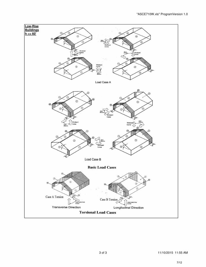
3. Building must be designed for all wind directions using the 8 load cases shown below. The
load cases are applied to each building corner in turn as the reference corner.
4. Wind loads for torsional cases are 25% of respective transverse or longitudinal zone load values.
Torsional loading shall apply to all 8 basic load cases applied at each reference corner.
Exception: One-story buildings with "h" <= 30', buildings <= 2 stories framed with light frame
construction, and buildings <=2 stories designed with flexible diaphragms need not be
designed for torsional load cases.
5. Per Code Section 28.4.4, the minimum wind load for MWFRS shall not be less than 16 psf.
2 of 3 11/10/2015 11:55 AM 6/12
"ASCE710W.xls" ProgramVersion 1.0
Low-Rise
Buildings
h <= 60'
3 of 3 11/10/2015 11:55 AM 7/12

Ada County, Idaho
2015-02595
RIVERSIDE #3
KKJ
Wind Shear Force CalculationsFrom 'ASCE 7-10 Wind Loading Analysis':
a = 3.00 feet 2a = 6.00 feet a = 3.00 feet 2a = 6.00 feet
Z1 = 8.96 psf Z1E = 15.99 psf Z1 = 5.86 psf Z1E = 11.46 psf
Z2 = -23.18 psf Z2E = -33.30 psf Z2 = -23.18 psf Z2E = -33.30 psf
Z3 = -17.28 psf Z3E = -22.73 psf Z3 = -14.65 psf Z3E = -18.91 psfZ4 = -15.86 psf Z4E = -21.26 psf Z4 = -12.52 psf Z4E = -16.25 psf
0.6*Wr
0.6*WrE
0.6*Ww
0.6*WwE
Wall
Line
Wind
Force
(psf)
Wall ht
(ft)
Truss
trib.
(ft)
wall line
dist. (ft) +
Wind
Force
(psf)
wall
ht (ft)
truss
trib (ft)
wall line
dist (ft) +
Shear,
Upper
(#) =
Wind
Force
(kips)
4 16.21 10 8 34 + 9.60 5 34 + = 4.40
Ww, WwE
= (Z2 + Z3) * 0.6 =
= (Z2E + Z3E) * 0.6 =
= (Z1 + Z4) * 0.6 =
= (Z1E + Z4E) * 0.6 =
3.5 psf
6.3 psf
14.9 psf
22.4 psf
LOAD CASE 'B'
'A' FACTORED LOADS
Wr, WrE
Location:
Project # :
Project:
Engineer:
LOAD CASE 'A'
4 16.21 10 8 34 + 9.60 5 34 + = 4.40
C 15.98 10 8 41 + 9.60 5 41 + = 5.24
8/12
Shear Wall (4) 11/10/2015
12:17 PMLocation: Ada County, Idaho
Project # : 2015-02595
Project: RIVERSIDE #3
Engineer: KKJ
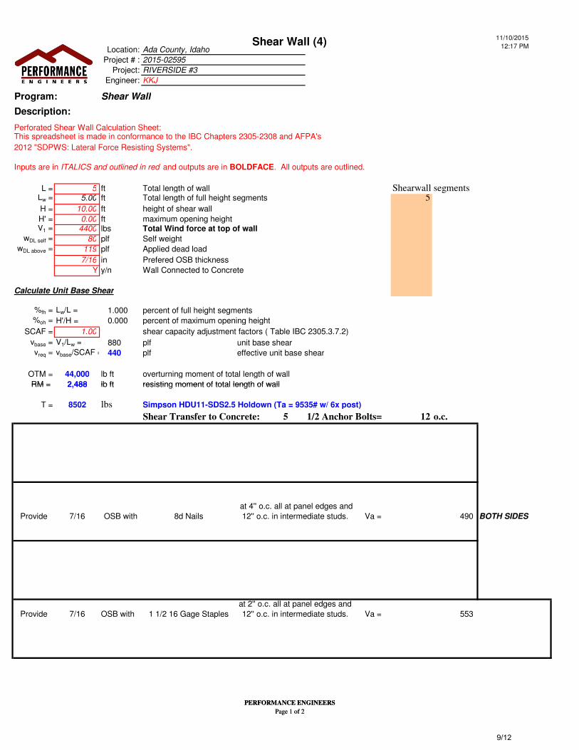
Program: Shear Wall
Description:
Perforated Shear Wall Calculation Sheet:This spreadsheet is made in conformance to the IBC Chapters 2305-2308 and AFPA's
2012 "SDPWS: Lateral Force Resisting Systems".
Inputs are in ITALICS and outlined in red and outputs are in BOLDFACE. All outputs are outlined.
L = 5 ft Total length of wall Shearwall segmentsLw = 5.00 ft Total length of full height segments 5H = 10.00 ft height of shear wall
H' = 0.00 ft maximum opening height V1 = 4400 lbs
wDL self = 80 plf Self weightwDL above = 119 plf Applied dead load
7/16 in Prefered OSB thickness
Y y/n Wall Connected to Concrete
Calculate Unit Base Shear
%fh = Lw/L = 1.000 percent of full height segments%oh = H'/H = 0.000 percent of maximum opening height
SCAF = 1.00 shear capacity adjustment factors ( Table IBC 2305.3.7.2)
vbase = V1/Lw = 880 plf unit base shearvreq = vbase/SCAF = 440 plf effective unit base shear
OTM = 44,000 lb ft overturning moment of total length of wall
RM = 2,488 lb ft resisting moment of total length of wall
Total Wind force at top of wall
PERFORMANCE ENGINEERS
Page 1 of 2
RM = 2,488 lb ft resisting moment of total length of wall
T = 8502 lbs
5 12 o.c.
0 0 0 0 0 - -
- - - - - - -
- - - - - - -
0 - 0 0 0 - -
Provide 7/16 OSB with 8d Nails Va = - 490 BOTH SIDES
- - - - - - -
0 0 0 0 0 - -
- - - - - - -
- - - - - - -
Provide 7/16 OSB with 1 1/2 16 Gage Staples Va = - 553
- - - - - - - 0
- - - - - - - 0 -
-
0
-
-
-
0 at 4'' o.c. all at panel edges and
12'' o.c. in intermediate studs.
at 2'' o.c. all at panel edges and
12'' o.c. in intermediate studs.
-
0
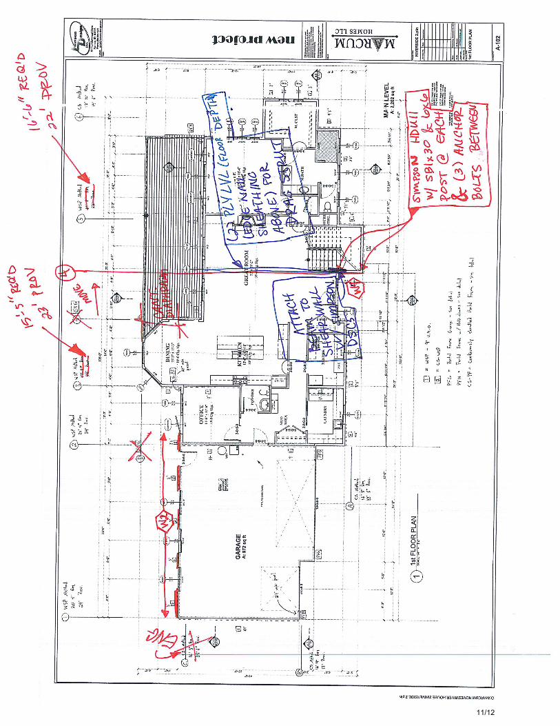
Simpson HDU11-SDS2.5 Holdown (Ta = 9535# w/ 6x post)
Shear Transfer to Concrete: 1/2 Anchor Bolts=
-
PERFORMANCE ENGINEERS
Page 1 of 2
9/12
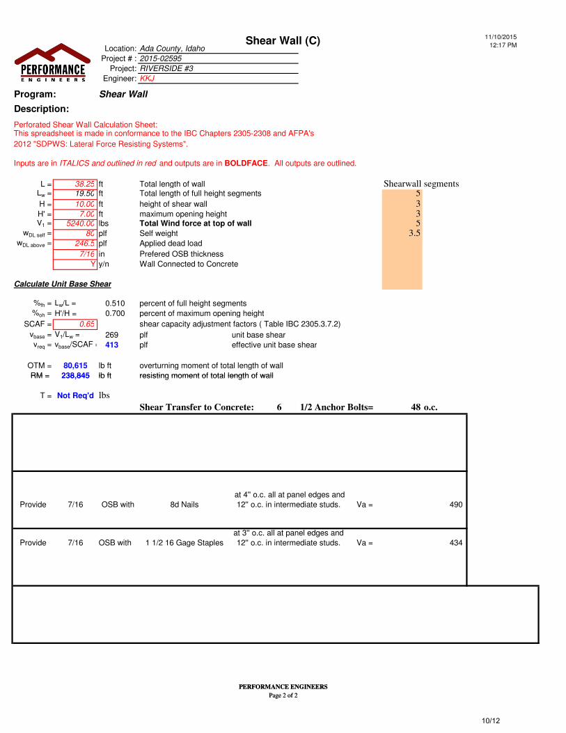
Shear Wall (C) 11/10/2015
12:17 PMLocation: Ada County, Idaho
Project # : 2015-02595
Project: RIVERSIDE #3
Engineer: KKJ
Program: Shear Wall
Description:
Perforated Shear Wall Calculation Sheet:This spreadsheet is made in conformance to the IBC Chapters 2305-2308 and AFPA's
2012 "SDPWS: Lateral Force Resisting Systems".
Inputs are in ITALICS and outlined in red and outputs are in BOLDFACE. All outputs are outlined.
L = 38.25 ft Total length of wall Shearwall segmentsLw = 19.50 ft Total length of full height segments 5H = 10.00 ft height of shear wall 3H' = 7.00 ft maximum opening height 3V1 = 5240.00 lbs 5
wDL self = 80 plf Self weight 3.5wDL above = 246.5 plf Applied dead load
7/16 in Prefered OSB thickness
Y y/n Wall Connected to Concrete
Calculate Unit Base Shear
%fh = Lw/L = 0.510 percent of full height segments%oh = H'/H = 0.700 percent of maximum opening height
SCAF = 0.65 shear capacity adjustment factors ( Table IBC 2305.3.7.2)
vbase = V1/Lw = 269 plf unit base shearvreq = vbase/SCAF = 413 plf effective unit base shear
OTM = 80,615 lb ft overturning moment of total length of wall
RM = 238,845 lb ft resisting moment of total length of wall
Total Wind force at top of wall
PERFORMANCE ENGINEERS
Page 2 of 2
RM = 238,845 lb ft resisting moment of total length of wall
T = Not Req'd lbs
6 48 o.c.
0 0 0 0 0 - -
- - - - - - -
- - - - - - -
0 - 0 0 0 - -
Provide 7/16 OSB with 8d Nails Va = - 490
- - - - - - -
Provide 7/16 OSB with 1 1/2 16 Gage Staples Va = - 434
- - - - - - -
- - - - - - -
0 0 0 0 0 - -
- - - - - - - 0
- - - - - - - 0 -
-
-
0 at 4'' o.c. all at panel edges and
12'' o.c. in intermediate studs.
-
at 3'' o.c. all at panel edges and
12'' o.c. in intermediate studs.
-
-
0
-
0
Shear Transfer to Concrete: 1/2 Anchor Bolts=
PERFORMANCE ENGINEERS
Page 2 of 2
10/12
11/12
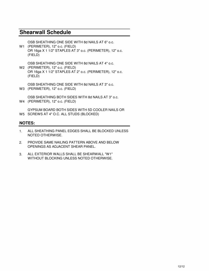
Shearwall Schedule
W1
OSB SHEATHING ONE SIDE WITH 8d NAILS AT 6" o.c.
(PERIMETER), 12" o.c. (FIELD)
OR 16ga X 1 1/2" STAPLES AT 3" o.c. (PERIMETER), 12" o.c.
(FIELD)
W2
OSB SHEATHING ONE SIDE WITH 8d NAILS AT 4" o.c.
(PERIMETER), 12" o.c. (FIELD)
OR 16ga X 1 1/2" STAPLES AT 2" o.c. (PERIMETER), 12" o.c.
(FIELD)
W3
OSB SHEATHING ONE SIDE WITH 8d NAILS AT 3" o.c.
(PERIMETER), 12" o.c. (FIELD)
W4
OSB SHEATHING BOTH SIDES WITH 8d NAILS AT 3" o.c.
(PERIMETER), 12" o.c. (FIELD)
W5
GYPSUM BOARD BOTH SIDES WITH 5D COOLER NAILS OR
SCREWS AT 4" O.C. ALL STUDS (BLOCKED)
NOTES:
1. ALL SHEATHING PANEL EDGES SHALL BE BLOCKED UNLESS
NOTED OTHERWISE.
2. PROVIDE SAME NAILING PATTERN ABOVE AND BELOW
OPENINGS AS ADJACENT SHEAR PANEL.
3. ALL EXTERIOR WALLS SHALL BE SHEARWALL "W1"
WITHOUT BLOCKING UNLESS NOTED OTHERWISE.
12/12