layaway procedures for u.s. army facilities, volume 1. decision
TRANSCRIPT
USACERL Technical Report M-91/23, Vol IJuly 1991
US Army Corpsof Engineers
Costruction Engineeiring AD-A240 054Research Laboratory ii hIiIlh i
Layaway Procedures forU.S, Army Facilities, Volume 1:Decision Criteria and Economics
by
D.R. Uzarski S.D. FoltzR.E. Rundus R.W. HarrisD.M. Bailey V.F. HockM.J. Binder O.S. MarshallD.E. Brotherson J.H. MyersC.S. Cartwright J.R. MyersN.M. Demetroulis K. PiskinR. Drozd V.L. Van BlaricumD.E. Ellsworth H.H. ZaghloulJ.E. Field
This two-volume report describes facility layaway pro-cedures for U.S. Army facilities, with an emphasis on FortDix, New Jersey,
Volume I focuses on decision criteria and the economicsof facility layaway. Decision matrices for choosing cost-behind differing maintenance and repair (M&R) standards ELECTeEare addressed. Strategies for both short- and long-term S 0 .5 199FUlayaway periods are described. The influence of theallowed reactivation period on M&R strategies is alsodescribed. Deactivation, periodic M&R, and reactivationfor buildings and utilities are discussed, as are environ-mental and security concerns.
Volume II addresses the specific inspection and mainte-nance and repair items associated with all of the differentsystems and components for buildings and utilities.These items are presented in a checklist format. A briefexplanatory section precedes each checklist.
Approved for public release; distribution Is unlimited, 9 1.09"96
91. :ý 1. )r"I

DI CLAI RE/o NO
THIS DOCUMENT IS BESTQUALITY AVAILABLE. TJt COPY
FURNISHED TO DTIC CONTAINEDA SIGNIFICANT NUMBER OF
`ES 3 -WHICH DO NOT
REPRODUCED FROMBEST AVAILABLE COPY

The contents of this report are not to be used for advertising, publication,or promotional purposes. Citation of trade names does not constitute anofficial indorsement or approval of the use of such commercial products.The findings of this report are not to be construed as an official Depart-ment of the Army position, unless so designated by other authorizeddocuments.
DESTROY THIS REPORT WHEN IT IS NO LONGER NEEDED
DO NOT RETURN IT TO THE ORIGINATOR
USER EVALUATION OF REPORT
REFERENCE: USACERL TR M-91/23, Layaway Procedures for U.S. Army Facilities, Voitone 1:Decision Criteria and Economics
Please take a few minutes to answer the questions below, tear out this sheet, and return it to USACERI..As user of this report, your customer comments will provide USACERL with information essential forimproving future reports.
1. Does this report satisfy a need? (Comment on purpose, related project, or other area of intcrest borwhich report will be used.)
2. How, specifically, is the report being used? (Information source, design data or proccdure,management procedure, source of ideas, etc.)
3. Has the information in this report led to any quantitative savings as far as manhours/contract dollarssaved, operating costs avoided, efficiencies achieved, etc.? If so, please elaborate.
4. What is your evaluation of this report in the following areas?
a. Presentation:
b. Completeness:
c. Easy to Understand:
d. Easy to Implement:
e. Adequate Reference Material:
f. Relates to Area of Interest:
g. Did the report meet your expectations?
h. Does the report raise unanswered (juestions?

i. General Comments. (Indicate what you think should be changed to make this report and futurereports of this type more responsive to your needs, more usable, improve readability, etc.)
5. If you would like to be contacted by the personnel who prepared this report to raise specific questions
or discuss the topic, please fill in the following information.
Name:
Telephone Number:
Organization Address:
6. Please mail the completed form to:
Department of the ArmyCONSTRUCTION ENGINEERING RESEARCH LABORATORYATTN: CECER-IMTP.O. Box 9005Champaign, IL 61826-9005

REPORT DOCUMENTATION PAGE F0m AWov~dOMB No. 0704-018Pub& reportng burden foe thi ooelon d InfomU1iofl Is *mi. to eartige I hour per reepona. Irnl•ding the tOe for reviewing instructons, searching exioting dta souwrce.gathering and nmintaining the d"a needed, and ooeplitrng and rwttdng the oolediton o informailon. Send comwrTWt regarding this burden etimate or any cther *@pd of thi
colection of infomation, including aug"lgom fot redujdng thi burden, to Waahngton Heedquettem Serv•o. Direcoo-de for Information Operations and Reports, 1215 JeWferon
Davi Htgiwemy, Suie 1204, Arlington, VA 22=-4302. wad to the Office of Manegeentm and Budget. Paperwork Reduction Prolect (0704-0188), Washington, DC 20503.
1. AGENCY USE ONLY (Leave Blsank) 2. REP.RT DATE 3. REPORT TYPE AND DATES COVEREDI July 1991 Final
4. TITLE AND SUBTITLE 5. FUNDING NUMBERS
Layaway Procedures for U.S. Ain-y Facilities, Volume 1: Decision Criteriaand Economics IAO EFC9Rl80 dated
September 19896. AUTHOR(S)
D.R. Uzarski, R.E. Rundus, D.M. Bailey, MJ. Binder, D.E. Brotherson. C.S. Carwright,N.M. Demetroulis. R. Drozd, D.E. Ellsworth, J.E. Field. S.D. Foltz, R.W. Harris, V.F. Hock,O.S. Marshall, J.H. Myers, J.R. Myers, K. Piskin, V.L. Van Blaricum, and H.H. Zaghloul
7. PERFORMING ORGANIZATION NAME(S) AND ADORESS(ES) 8. PERFORMING ORGANIZATIONREPORT NUMBER
USACERLPO Box 9005 USACERL TR M-91123,Champaign, IL 61826-9005 Vol I
9. SPONSORING(MONITORING AGENCY NAME(S) AND ADORESS(ES) 10. SPONSORING/MONITOP;NGAGENCY REPORT NUMBER
TRADOCATTN: ATEN-FEFort Monroe, VA 23651-5000
11. SUPM-MICNTAnY NOTES
Copies are available from the National Technical Information Service, 5285 Port Royal Road,Springfield, VA 22161.
12a. DISTRIBUTION/AVAILABILITY STATEMENT 12b. DISTRIBUTION CODE
Approved for public release; distribution is unlimited.
13. ABSTRACT (Maximum 200 words)
This two-volume report describes facility layaway procedures for U.S. Army f.,cilities. with an emphasis on Fort Dix, NJ.
Volume I focuses on decision criteria and the economics of facility layaway. Decision matrices for choosing cost-effectivelayaway strategies are presented. The concepts behind differing maintenance and repair (M&R) standards are addressed.Strategies for both short- and long-term layaway periods are described. The influence of the allowed reactivation period onM&R strategies is also described, Deactivation, periodic M&R, and reacivation for buildings and utilities are discussed, asare environmental and security concerns. The report conclude, that facility layaway is technically feasible at an affordableCost.
Volume 11 addresses the specific inspection and M&R itcms associated with all of the different systems and components forbuildings and utilities. These items are presented in a checklist format. A brief explanatory section precedes each checklist.
14, SUBJECT TERMS 15. NUMBER OF PAGES
facility layaway 146Fort Dix, NJ 16. PRIcE CODE
base closure base realigunment17. SECURITY cLASSlFICATION 18. SECURITY CL.ASSIFICATION 19. SECURITY CLASSIFICATION 20. LIMITATION OF ABSTRACT
OF REPORT OF THIS PAGE OF ABSTRACT
Unclassified Unclassified Unclassified SAR
NSN 7540-01-280-5500 Sm do Form 298 ft.m. 2-89)Preceti I/y ANSI S1 23e-182Ie-102
FOREWORD
This research was conducted for the U.S. Army Training and Doctrine Command (TRADOC) under
Intra-Anny Order (IAO) EFC9R180, dated September 1989. The TRADOC technical monitor was
Gregory Capra, ATEN-FE. His support is very much appreciated.
The work was conducted by the Engineering and Materials Division (EM), the Energy Systems and
Utilities Division (ES), and the Environmental Division (EN) of the U.S. Army Construction Engineering
Research Laboratory (USACERL). Dr. Paul HowdysheU is Chief of USACERL-EM, Dr. Gilbert
Williamson is Chief of USACERL-ES, and Dr. Edward W. Novak is the Acting Chief of USACERL-EN.
The USACERL technical editor was Gordon L. Cohen, Information Management Office.
Donald Brotherson is a member of the Small Homes Council - Building Research Council,
University of Illinois. John H. Myers is the Assistant Dean for Research of the Center for Architectural
Conservation, College of Architecture, Georgia Institute of Technology. James R. Myers is from JRM
Associates, Franklin, Ohio. Nicholas M. Demetroulis is from NMD & Associates, Alexandria, Virginia.
The authors gratefully acknowledge contributions of Ed Tuckey, U.S. Army Materiel Command
(AMC); the many TRADOC personnel who contributed to the in-progress-review meetings and in
reviewing the draft submittals including COL Tadahiko Ono, LTC Michael E. Stovall, Ray Spunzo, Steve
Mason, Conrad Browe, Phil Prisco, Ron Walkup, Ken Ycager, Bill Dancy, Mr. George Evans, James Day,
and Philip Columbus; the FORSCOM personnel who reviewed the initial submittal including Bill
Timmerman and Don Turner, the numerous individuals from Fort Dix including LTC Donnie Henley, Joe
Buerster, Al Snyder, Bill Eger, Jean Johnson, Leo Fontaine, Joe Price, B.J. Forsten, Steve Whitmore,
Richard Dann, Malcolm Knighton, Joe Haug, Jerry Munko, Richard Ameigh, Ray Ortega, Fire Chief J.
Sweeney, and Russ Freeborn; Teresa Pin, Dale Cover, Larry Windingland, Edgar Neely, and Bill Wang
from USACERL; Ken Zandlcr, USAEHSC; and Ed Perry, English Brothers Construction Company,
Champaign, IL.
COL Everett R. Thomas is Commander and Director of USACERL, and Dr. L.R. Shaffer is
Technical Director.
Alessltb torOTI'S GRA&I"" TIc T'ABUnairnounced 03 ust~fic"atio
Dtstributlont
Availability Codes
lAval2. anid/orDistt ISpeolal
2

CONTENTS
SF 298FOREWORD 2LIST OF FIGURES AND TABLES S
INTRODUCTION ..................................................... 9BackgroundObjectiveApproachScopeMode of Technology Transfer
2 DECISION MATRIX DEVELOPMENT AND USE ........................... 11VariablesDecision MatrixGeneral Recommendation for Army Facility Layaway Decisions
3 FACILITY INSPECTION REQUIREMENTS ............................... 22Inspection PurposesPreferred Approach versus Minimal ApproachInspection ScheduleInspection EffortInspector Judgment
4 BUILDING SYSTEMS ................................................. 25Building ComponentsVentilation RequirementsFurniture and Bedding IssuesDo-Nothing Facilities
5 UTILITY SYSTEMS .................................................. 35Steam Heating System ModelingSteam Heating SystemsGas Distribution SystemPetroleum Products Storage SystemsSanitary SystemsElectrical Distribution SystemBuilding Monitoring System
6 ECONOMIC ANALYSIS AND BUDGETS ................................. 44Economic Analysis MethodVariablesM&R CostsEUAC CalculationRelationship to Decision MatrixBudget DeterminationPrioritizing M&R Requirements
3

CONTENTS (Cont'd)
7 ENVIRONMENTAL ASPECTS AND CONSIDERATIONS ........................ 62Major IssuesSummary of Environmental Considerations
8 SECURITY ISSUES .................................................. 64
9 CONCLUSIONS AND RECOMMENDATIONS .............................. 66ConclusionsRecommendations
METRIC CONVERSION TABLE 68
REFERENCES 68
APPENDIX A: Fort Dix Building Ventilation Plan 71APPENDIX B: Fort Dix Bedding Plan 80APPENDIX C: Fort Dix Do-Nothing Facility Listing 81APPENDIC D: Steam Heating System Modeling 82APPENDIX E: Procedure for Computing Costs for Steam Distribution System 97APPENDIX F: UST Costs 103APPENDIX G: Fort Dix UST Issues 106APPENDIX H: Fort Dix Sanitary System Issues 109APPENDIX I: Building Monitoring Systems 111APPENDIX J: Layaway Unit Costs 114APPENDIX K: Equivalent Uniform Annual Cost (EUAC) Summaries 118
LIST OF ABBREVIATIONS 142
DISTRIBUTION
4

FIGURES
Number Page
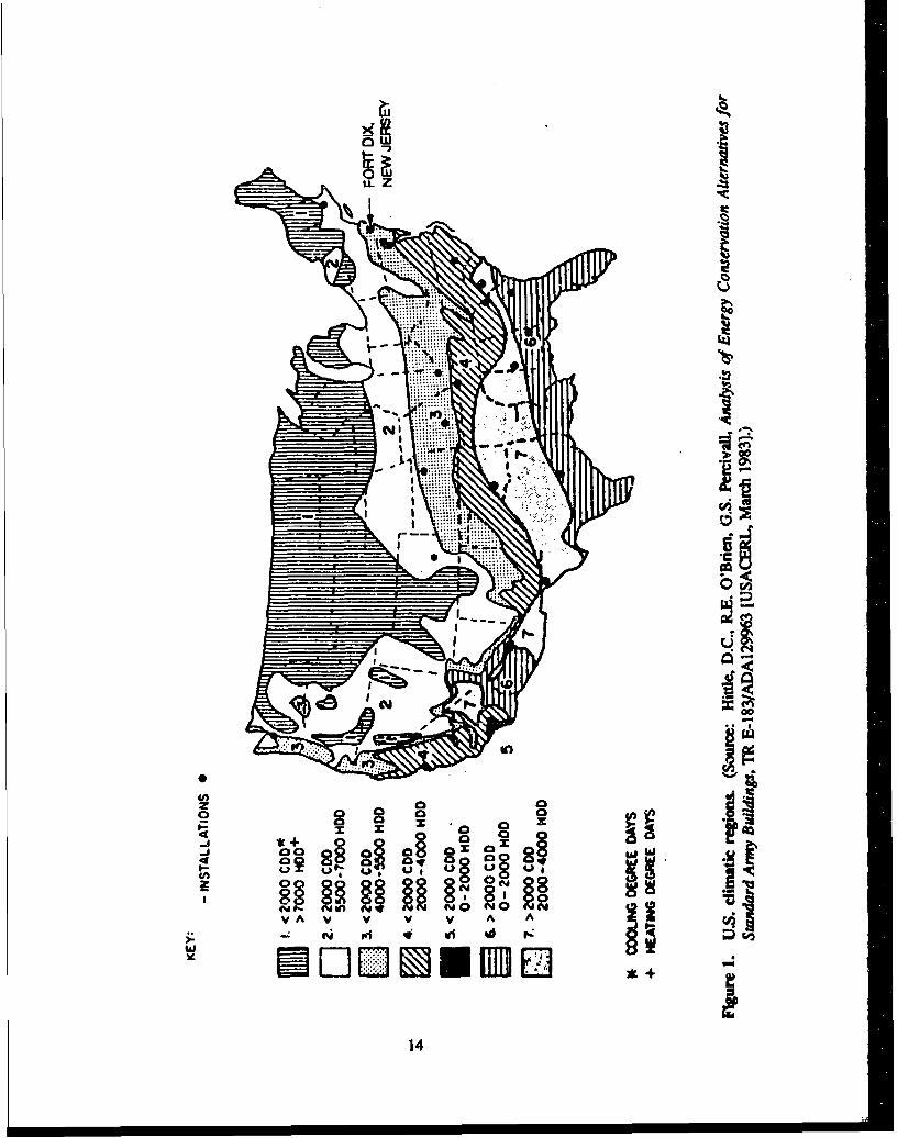
I U.S. Climatic Regions 14
2 Maintenance Standard Concept 16
3 Decision Matrix Concept 17
4 Decision Matrix for Buildings 18
5 Decision Matrix for Underground Steam Heat Distribution System 18
6 Decision Matrix for Electrical Distribution System 19
7 Decision Matrix for Underground Storage Tanks 19
8 Decision Matrix for Sanitary Systems 20
9 Example Inspection and M&R Checklist 21
10 Comparison of Alternatives Through EUAC 44
11 Decision Matrix Example With EUACs 50
12 Deactivation Budgets for Differing M&R Strategies 51
13 Periodic M&R Budgets (Annual) for Differing M&R Strategies 53
14 Reactivation Budgets for Differing M&R Strategies 53
15 Total M&R Budgets for Differing M&R Strategies 54
16 Budget Comparisons to PRV for Layaway Period Greater Than 1 Year 55
17 Budget Comparisons to PRV for Layaway Period Less Than 1 Year 56
18 Comparison to Existing Budgets for Preferred M&R Standard 57
19 Comparison to Existing Budgets for Minimal M&R Standard 58
Dl Fort Dix Steam Heating Distribution System 83
D2 Actual Steam Produced v. SHDP Output (Building 5881 and HRI) 88
I1 Radio Commmunications System Architecture 112
5

TABLES
Number Page
I Recommended Inspection Frequencies 23
2 Component Layaway Costs for Rolling Pin Barracks 46
3 Example Computation of Budget for Entire Layaway 52
4 Recommended Priority List for Facility Deactivation 60
5 Recommended Priority List for Periodic M&R 61
Dl Fort Dix Boiler Information 82
D2 Fort Dix Steam Production 84
D3 HEATLOAD Building Categories and Energy Consumption Equations 86
D4 Fort Dix Steam Demand (November 1988 - October 1989) 87
D5 Fort Dix Steam Demand (65 "F Base Temperature) 90
D6 Fort Dix Steam Demand (45 °F Base Temperature) 91
D7 SHDP Annual Steam Demand and Cost, Scenario 1 93
D8 SHDP Annual Steam Demand and Cost, Scenario 2 93
D9 SHDP Annual Steam Demand and Cost, Scenario 3 93
DIO SHDP Annual Steam Demand and Cost, Scenario 4 94
D1I SHDP Annual Steam Demand and Cost, Scenario 5 94
D12 SHDP Annual Steam Demand and Cost, Scenario 6 94
D13 SHDP Annual Steam Demand and Cost, Scenario 7 95
D14 SHDP Annual Steam Demand and Cost, Scenario 8 95
El Costs for Preferred Warm/Hot Steam Distribution System Procedures 98
E2 Costs for Prcferred Cold Stcam Distribution System Procedures 99
E3 Costs for Minimal Warm/Hot Steam Distribution System Procedures 100
E4 Costs for Minimal Cold Steam Distribution System Procedures 101
6
TABLES (Cont'd)
Number Page
E5 Cost Per Linear Foot of Steam Piping 102
Fl UST Closure Costs 103
F2 Costs for UST Closure-Related Field Work 104
F3 UST Installation-Related Costs 105
GI Affected Petroleum Products Storage Tanks 107
I1 Radio Alarm System Costs 113
7

LAYAWAY PROCEDURES FOR U.S. ARMY FACILITIES,VOLUME I: DECISION CRITERIA AND ECONOMICS
1 INTRODUCTION
Background
Base closure and realignment' is causing significant changes in mission and population at severalArmy installations. Within the U.S. Army Training and Doctrine Command (TRADOC), severg.l forts arebeing affected, but the greatest mission change is occurring at Fort Dix, NJ. There, the mission has beenchanged to primarily support Army Reserves and provide a site for mobilization training capabilities. Thisnew mission is leaving vacant many facilities that have been regularly occupied. TRADOC plans to usethese facilities intennittently to accommodate surges of Reserve component training each year. Otherfacilities must be maintained for occupancy on short notice as mobilization training requirements developmonths or years from now. This affects hundreds of thousands of square feet of building space. Existingregulations' address some procedures, but do not provide comprehensive guidance for layaway(deactivation, periodic maintenance and repair, and reactivation) of specific buildings or building groupswith their related utility networks and grounds for the lowest life-cycle cost in maintaining and operatingthose facilities. Neither do any other Army documents provide the necessary guidance.
The U.S. Army Construction Engineering Research Laboratory (USACERL) was tasked byTRADOC to develop layaway procedures on a life-cycle cost basis, with an emphasis on the facilities atFort Dix.
Objective
The objective of this study is to develop procedural facility layaway guidelines, based on the lowestlife-cycle cost, for individual buildings, building groups, related utility networks or subnetworks, andsurrounding grounds.
Volume I describes the decision criteria and economic considerations involved in developing theguidelines. Volume II presents the procedures and checklists for each facility component.
Approach
Background information on the problem was gathered, although there was little available. A varietyof Fort Dix site-specific facility information was reviewed, site visits were made to Fort Dix, and allavailable technical literature was studied. This included literature from equipment manufacturers, materialsuppliers, government agencies, and appropriate trade journals. Organizations known to be involved withfacility layaway were contacted and interviewed, These organizations included U.S. Army Materiel
' Base Realignments and Closures: Report of the Defense Secretary's Commission (Department of Defense, December 1988),2 Army Regulation (AR) 210-17, Inactivation of Installations (Headquarters, Department of the Army [HQDA], January 1967).
9

Command (AMC), the U.S. Navy, the National Park Service (NPS), the National Aeronautics and SpaceAdministration (NASA), and others. Finally, studies performed by other government laboratories werereviewed.
A checklist of procedures was identilied for each different type of facility component and material.The approach taken divided the facilities into two distinct groups: buildings and utility systems. Then,each group was further divided into specific components. The intent was to make the component check-lists as generic as possible to facilitate use at other installations. However, since the focus of the studywas Fort Dix, components and/or materials present at other installations but not subject to layaway at FortDix are not included. These checkiists incorporate existing state-of-the-art technologies for facilitylayaway. This project did not include research into new and innovative methods.
A matrix approach was integrated with the checklists. The matrix incorporated the decision vari-ables of length of the layaway period, allowed reactivation time, and three levels of maintenance andrepair (M&R) activity. The life-cycle cost analyses were based on those variables. The specific costsused in the analyses pertain to Fort Dix. Geographical and climatic variables, outside of those applicableto Fort Dix, were not considered in developing the checklists.
Facility issues specifically or uniquely applicable to Fort Dix were studied to provide a completeanalysis necessary for a proper layaway plan.
Scope
This report addresses the procedures for the layaway of U.S. Army facilities. These include tasksassociated with deactivation, periodic M&R, and reactivation. The procedures are applicable to the varietyof facilities scheduled for layaway at Fort Dix, and to facilities at other locations with similar climate.The procedures are supplemented and supported with cost analyses. Where appropriate, explanations aregiven on the assumptions used and the methods employed.
Because of the complexity of developing the needed guidelines and the short timeframe specifiedby TRADOC, this study should be considered a Phase I effort that identifies and consolidates existingtechnologies into a single package, with main emphasis on Foit Dix.
Mode of Technology Transfer
This report has been prepared in two volumes to assist in the technology transfer process. VolumeI is intended primarily for installation and Major Command (MACOM) managers and budgeteers in devel-oping strategies and deciding "big picture" issues. Volume II is intended for facility inspectors, planners,cstimators, and others in identifying specific work items, preparing work orders, and preparing contracts.Some topics in Volume I should also be of interest to those same people.
Since this report is not comprehensive in terms of facility and component types addressed, tech-nology transfer through a Department of the Army Technical Manual or Pamphlet, or through a similarMACOM publication, is not recommended. If and when layaway procedures are developed for additionalkinds of facilities and locations representative of the Army as a whole, incorporation into a technicalmanual or pamphlet would be recommended.
10

2 DECISION MATRIX DEVELOPMENT AND USE
The procedures that should be employed to properly lay away a facility on a cost-effective basisdepend on a number of variables. A method is needed that allows the decisionmaker to consider thosevariables when planning an M&R strategy over the layaway period. A simple decision matrix providesthat method. A proposed matrix is given at the end of this chapter, after a discussion of the variables thatmust go into the matrix.
Variables
The kcy variables considered in this study are:
"* Deactivation period
"• Reactivation period
"* "Heat" and "no heat" alternatives
"* Facility type and use
"* Material and equipment inventory
"* Climate
"* Maintenance standards
"• Life-cycle costs.
Each of these is discussed below.
Deactivation Period
The length of time that a facility will lay dormant is a key factor in developing M&R strategies.This is due to the cyclic nature of M&R activities. Generally, performed M&R will serve its intendedpurpose for a minimum of 1 year. Beyond that, however, effectiveness diminishes, resulting in the needto perform it again. The frequency of a given M&R application depends on the facility, component, mate-rial, initial condition, level of M&R performed, quality, climate, and a host of other factors. If thatfrequency is less than the specified deactivation period, the need for the M&R activity becomes ques-tionable. Activities needed to preserve the facility clearly must be done, but the necessity of othersbecomes a subjective judgment. M&R frequency factors, when coupled to a variable or unknown reactiva-tion period, lead to the nearly impossible task of developing M&R strategies tied to any specific intervalof time. If, however, strategies are considered on a more general basis, the task becomes manageable.When the facilities are considered in terms of "short" and "long" layaway periods, practical and usablestrategies can be developed.
A short layaway period is defined to be 1 year or less. The basis for this definition is to accommo-date the annual scheduling of reservists occupying a portion of the deactivated facilities. A short layaway
II

period can be used to provide a planned rotation of deactivation and reactivation procedures to enhancethe longevity of the facilities through appropriate M&R investment.
Long-term layaway is considered to be greater than 1 year. Since "long-term" becomes open endedby that definition, a 10-year target was used as the benchmark to plan M&R needs and budgets. Ten yearsis a practical definition because no one really knows when the facilities, if ever, will be needed, and manycomponents exposed to the elements will reach the end of their expected lives at that time. If, toward theend of that period, it appears that the facilities will continue to stand idle, then a complete condition andM&R strategy evaluation should be undertaken to map out the needs for the next decade.
Both the short- and long-term layaway scenarios require scheduled M&R to combat anticipated
annual deterioration of the facilities' components.
Reactivation Period
The reactivation period is also a critical variable. This relates to the required readiness state of thefacility and level of IM&R needed to sustain that readiness. The shorter the reactivation period desired,the higher the sustained readiness state must be because of the shortage of time available to performdeferred M&R. A higher readiness state requires performing more periodic M&R during layaway anddeferring less to the reactivation phase.
A critical factor in selecting appropriate periods for which to establish M&R strategies is the needto supply steam to the various buildings for heat and other purposes. Once boiler plants are deactivated,a minimum of 45 days is needed to restore them to an operational condition. This 45-day juncture thenserves as a logical division point for M&R strategies.
In general, it was found that if the required reactivation period was less than 45 days, a commonstrategy could be devised. The exception to this less-than-45-day strategy would be if the reactivationperiod is so short that there is insufficient time for reactivation. For this case, inactive facilities must betreated as if they were active. If a reactivation time of greater than 45 days were acceptable, a commonstrategy could also be devised.
"Heat" and "No Heat" Alternatives
These alternatives are considered in conjunction with the decision about the reactivation period dis-cussed above. Since the 45-day division point is due largely to the requirements of laying away boilers,it is assumed that the facility will not be heated if the reactivation period is greater than 45 days. If thereactivation period is less than 45 days, heating may or may not be viable. The boilers could remainactive, but steam does not necessarily need to be distributed to the buildings.
The impact of "heat" versus "no heat" affects some facility components much more so than others.Primarily, the components that receive or transmit steam or condensate are the ones most affected. Thesecomponents generally have very specific M&R procedural requirements directly tied to use.
It should be noted that the heating scenario used in this study assumes a 45 OF* building interiortcmperature during the heating season. This temperature was chosen for fuel economy. However, sincemaintaining that temperature can be difficult due to mechanical breakdown or other factors, and since
"U.S. standard units of measure are used in this report. A metric conversion table is printed on page 69.
12

temperature variations within a building can occur, it is further assumed that the plumbing systems in allbuildings will be drained and weatherproofed even if the buildings are to be heated.
The decision to heat or not to heat should stem from economics. For facilities to be heated, the costof that heat must be amortized through a reduction in the specific M&R costs that would result from not
heating. As cost analysis will show (see Chapter 6), heating is not economical if the facility is properlydeactivated and maintained as per the recommended guidelines.
If proper deactivation procedures are carried out, the condition of facility components will bemaintained at an acceptable level of serviceability commensurate with reactivation time. Past performanceof several building components at Fort Dix has revealed a tendency for buildings to deteriorate when theyare not heated. While heat is a factor in some deterioration modes, it is not the only factor, or even themost critical one. The U.S. Park Service, countless individuals, and others winterize buildings in coldclimates without the use of heat. Humidity control through ventilation is a much more critical parameter,and is addressed in Chapter 4.
Facility Type and Use
Logically, facility type and use should be factors in developing M&R strategies. For example, anadministration building would be expected to have different M&R needs than a warehouse. Initially, itwas thought that the various facility types and uses could be distinguished through the applicable categorycodes at Fort Dix. Realignment activities at Fort Dix encompass 28 category cndes that include eightdifferent construction types. In theory, different checklists should be developed for each. Because thatapproach would have resulted in large numbers of lists with considerable amounts of technical materialbeing duplicated, the idea was dropped in favor of establishing the checklists by component type. Withfacility components (e.g., roofs, electrical systems) as the basis for the checklists, inspectors and otherusers can simply apply the appropriate component checklists to any building, thus making the product ofthis study easier to implement and use. As displayed in Chapters 4 and 5, each component checklist pro-vides for four differing strategies based on the variables of deactivation period, reactivation period, andheat/no heat discussed previously. This approach also provides for a more generic application of theseprocedures to other installations.
Subcomponerts and Materials
Although facility components make a logical basis for developing checklists, a further breakdownis required for many. This is because a facility component may consist of a variety of subcomponents,and different materials may be in place. For example, the exterior component of a building includes assubcomponents exterior cladding, windows, and doors. Each has its own M&R needs. Also, the differentpossible materials used in these subcomponents have different M&R needs. For example, windows withwood frames need to be painted, but vinyl-coated windows do not.
The layaway procedures developed here incorporate the subcomponents and materials found at Fort Dixas well as some of the more common types not found there. Again, this approach was taken to promotemore generic application of the procedures.
Climate
Fort Dix is located in a temperate climate. Figure I shows the climatic region associated with NewJersey and those for the rest of the United States. The installation is subject to severe freeze-thaw cyclesand high humidity. Both of these factors have been accounted for in developing the layaway procedures.
13
...... ....
tnv
o0 0 M
oil 1000 oxo ox4 00 0 CY
I
14

Conceivably, in terms of climate, the procedures are applicable to other installations in the same region
as Fort Dix. Application to installations outside that region should be considered with caution, however.
Maintenance Standards
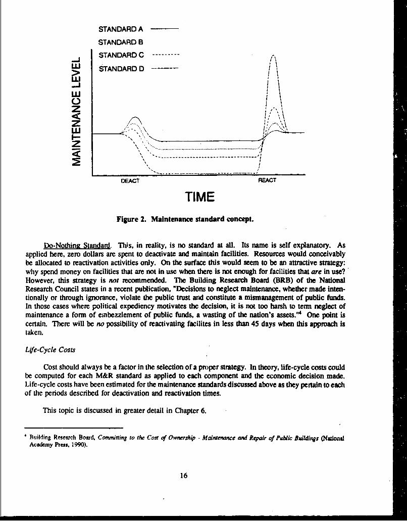
A maintenance standard could be defined as the level of maintenance necessary to sustain a facilityat a desired or given condition level. Each condition level would presumably enhance or detract from themission-readiness of a facility. As Figure 2 illustrates, a large number of maintenance standards couldbe created for a given facility. Unfortunately, while this concept poses an interesting relationship fortheorists, very little has ever been accomplished in developing practical standards that actually relate tolevel of condition. Condition-rating parameters are generally only in an embryonic state and then for onlycertain components. Also, actual M&R efforts needed to sustain a given condition level have beenbarely researched.
This study attempts to define various levels of maintenance that would be both meaningful andpractical for facility layaway. Two levels of standards resulted: "Preferred" and "Minimal." Each isdescribed below. Each was developed using life-cycle costs and mission-driven requirements as primecriteria. A third standard, which requires doing nothing, is also discussed. These would correspondroughly to standards B, C, and D, respectively, in Figure 2.
Preferred Standard. This standard was created to reflect the professional engineering judgment ofUSACERL in-house and contracted professionals. The primary issues include life-safety, serviceability,and overall component integrity. The focus is on preventive maintenance and early detection andcorrection of deficiencies that, if left alone, will accelerate facility degradation and lead to higherreactivation costs. By implementing the Preferred standard, a facility can remain in satisfactory conditionthroughout a layaway period with reactivation and life cycle costs held to a minimum.
When a building to be closed is on the National Register of Historic Places or is eligible for theNational Register, it is recommended that the Preferred approach be followed. The Preferred approachshould provide for the appropriate stabilization of all buildings by minimizing intervention and reducingthe rate of deterioration to the maximum extent possible. National Historic Landmarks or structures ofexceptional significance should have layaway plans reviewed individually by cultural resource specialists.
Minimal Standard. This was developed as an absolute minimum level of effort that must beexpended if the facilities are ever to be used again. Some M&R must be accomplished or else extremedeterioration will eventually result, rendering the facility unusable, perhaps even beyond a condition fromwhich it could be economically corrected at the reactivation phase. Thus, cost factors are a premiumconsideration in implementing the Minimal standard. Alternate schemes for periodic M&R wereincorporated to prolong component integrity without incurring the cost of a Preferred maintenancestandard. Using a building exterior closure component as an example, the Preferred standard to repair abroken window would be to reglaze the affected area with new material. Alternately, the Minimalstandard that requires the opening be covered with plywood and scaled with caulk. The Minimal strategyprovides a necessary solution and is more economical in the short run, but results in higher costs atreactivation. This example illustrates how costs can be deferred until reactivation. The clichd, "you canpay me now or you can pay me later" is pertinent.
M.Y. Shahin, D.M. Railey, D.E. Brothcr'on, Acnmbrane and Flashing Condition Indexesfor Built Up Roofs: Vol 1: Developmentof the Procedure. Technical Report (TR) M-87/13/ADA190367 (USACERL. September 1987); M.Y. Shahin, D.M. Bailey, D.E.Brotherson. Membrane and Flashing Condition Indexesfor Built. Up Roofs: Vol i/: Inspection and Distress Manual, TR M-87/13/ADA190368 (USACERL, September 1987).
15
STANDARD A
STANDARD B
STANDARD C-------- %'J I,> STANDARD D>uJ_
Z %
" . . .. ............... ......................................S,~~ ......................... -
DEACT REACT
TIME
Figure 2. Maintenance standard concept.
Do-Nothing Standard. This, in reality, is no standard at all. Its name is self explanatory. Asapplied here, zero dollars are spent to deactivate and maintain facilities. Resources would conceivablybe allocated to reactivation activities only. On the surface this would seem to be an attractive strategy:why spend money on facilities that are not in use when there is not enough for facilities that are in use?However, this strategy is not recommended. The Building Research Board (BRB) of the NationalResearch Council states in a recent publication. "Decisions to neglect maintenance, whether made inten-tionally or through ignorance, violate the public trust and constitute a mismanagement of public funds.In those cases where political expediency motivates the decision, it is not too harsh to term neglect ofmaintenance a form of embezzlement of public funds, a wasting of the nation's assets.'"4 One point iscertain. There will be no possibility of reactivating facilites in less than 45 days when this approach istaken.
Life-Cycle Costs
Cost should always be a factor in the selection of a proper strategy. In theory, life-cycle costs couldbe computed for each M&R standard as applied to each component and the economic decision made.Life-cycle costs have been estimated for the maintenance standards discussed above as they pertain to eachof the periods described for deactivation and reactivation times.
This topic is discussed in greater detail in Chapter 6.
Building Research Board, Committing to the Cost of Ownership - Maintenance and Repair of Public Buildings (NationalAcademy Press, 1990).
16

Decision Matrix
Figure 3 illustrates the decision matrix as described in this chapter. Figures 4 through 8 providethe matrices for buildings and the various utility systems as they pertain to Fort Dix. It should be notedthat two systems do not have decision matrices: natural gas systems and boilers. For gas, safety is suchan overwhelming consideration that there is but one correct approach--valves must be sec-. ed, vents madeoperational, and leaks repaired. Due to the unique boiler plant arrangements at Fort Dix, the only recom-mended approach is to do a dry layup of the boilers. The boilers are discussed in detail in Chapter 5.
Included in the decision matrix, either directly or indirectly, are all the variables previouslydescribed. To use the matrix, policy decisions must be made about the allowed reactivation time and thelength of time the facilities will be laid away. These decisions, which are expected to be made outsideof the engineer's domain, are a product of operations planning and can pertain to certain or all facilities.
The operational decisions related to facility layaway determine which quadrant of the matrix willbe used. Each quadrant has associated with it a choice of maintenance standard. Each standard, in turn,has specified procedures (see Figure 9, for example) applicable to all facility components that are to belaid away. The choice of standard can be de' I though the application of a life-cycle cost analysis. Adiscussion on the development of the procdures checklists follows in the next two chapters. A key tohow to interpret and use the checklists is provided in Volume II, Appendix A.
DEACTIVATION PERIOD (YEARS)REACT.PERIOD LESS THAN 1 YEAR GREATER THAN 1 YEAR(DAYS)-
PREFSR. MINIMAL DO NOTH PREFER. MINIMAL DO NOTH
LESS HEAT LCC - C, LCC m C4 LCC - C, LCC - C,, LCC - C1, LCC - C,.THAN
45 NOHE-T LCC- C" LCC - C, LCC - C,I LCC - C,, LCC - C,,DAYS H4EAT
GREATERTHAN
LCC - C, LCC -C, LCC - C, LCC - C,, LCC- C, LCC -C,,
DAYS
Figure 3. Decision matrix concept.
17
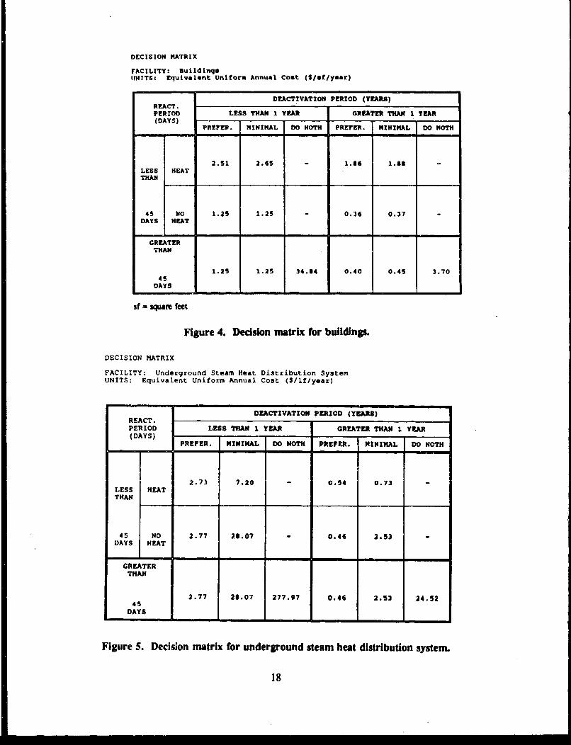
DECISION MATRIX
FACILITY: suildinqsNInTS: Equivalent Uniform Annual Cost (S/mt/year)
DEACTIVATION PERIOD (YEARS)REACT.PERIOD LESS THAN I YEAR GREATER THAN I TEAR(DAYS)
PREFlZER. MINIMAL DO MOTH PREFER. MINIMAL DO MOTH
2.51 2.65 1.36 1.88LESS HEAT
THAN
45 NO 1.25 1.25 0.036 0.37DAYS HEAT
GREATERTHAN
1.25 1.25 34.84 0.40 0.45 3.7045
DAYS
sf = squa feet
Figure 4. Decision matrix for buildings.
DECISION MATRIX
FACILITY: Underground Steam Heat Distribution SystemUNITS: Equivalent Uniform Annual Cost ($/if/year)
DEACTIVATION PERIOD (YEARS)REACT.PERIOD LESS THAN I YEAR GREATER THAN 1 YEAR(DAYS)
PREFER. MINIMAL DO MOTH PREFER. MINIMAL DO MOTH
2.73 7.20 - 0.54 0.73LESS HEATTHAN
45 NO 2.77 28.07 - 0.46 2.53DAYS HEAT
GREATERTHAN
2.77 23.07 277.97 0.46 2.53 24.5245
DAYS
Figure 5. Decision matrix for underground steam heat distribution system.
18

DECISION MATRIX
FACIITTY : Electrical SystemUNITS: Equivalent Uniform Annual Cost ($/year/for whole system)
DEACTIVATION PERIOD (YEARS)REACT.PERIOD LESS THAN 1 YEAR GREATER THAN I YEAR(DAYS)
PREFERRED MINIMUM PREFERRED MINIMUM
LESST11AN 10700 12700 3300 5800
45
DAYS
GREATER
THAN10700 12700 3300 5800
45DAYS
Figure 6. Decision matrix for electrical distribution system.
DECISI"ll MATRIX
FACILITY: Underground Storage TanksUNITS: Equivalent Uniform Annual Cost (S/standard tank/year)
EACT... .. .DEACTIVATION PERIOD (YEARS)REACT . . . ..PERIOD LESS THAN 1 YEAR GREATER THAN 1 YEAR(PAYSe) . ,PERM DISPOSE STORE PERM DISPOSE STORE
TEMP IN 6 A RE- IN & & RE-PLACE REPLACE INSTALL PLACE REPLACE INSTALL
LESSTHAN
9800 36000 4700 3500 4000
45DAYS
GREATERT1IAN
9800 36000 30100 30100 4700 3500 4000
Figure 7. Decision matrix for underground storage tanks.
19

DECISION MATRIX
FACILITY: Sanitary SystemUNITS: Equivalent Uniform Annual Cost (S/year/for whole system)
DEACTIVATION PERIOD (YEARS)REACT. *PERIOD LESS THAN 1 YEAR GREATER THAN 1 YEAR(DAYS)
PREFERRED MINIMUM* PREFERRED MINIMUM*
LESSTHAN
191400 160100 62500 4890045
DAYS
GREATERTHAN
191400 160100 62500 4890045
DAYS
* Some capital deterioration may occur with minimal maintenance. Largecapital expenditures may be required upon reactivation.
Figure 8. Decision matrix for sanitary systems.
When the chosen matrix quadrant and M&R standard are combined, an M&R strategy results. Forexample, buildings could be considered for long-term (greater than 1 year) layaway with a long (greaterthan 45 day) reactivation period. The life-cycle costs for the different maintenance standards indicate thatthe Preferred standard is most economical (Figure 4). Then, the aprofpeate procedures meeting thosecriteria found on the various building checklists should be used.
If economics, instead of mission, becomes the primary facto in det.loping an appropriate M&Rstrategy, the maintenance standard/decision matrix quadrant combinaion that yields the lowest life-cyclecost should be chosen. This M&R strategy may, however, be incompatible with mission.
General Recommendation for Army Facility Layaway Decisions
From an economics perspective, it would be most beneficial to the Army to put applicable facilitiesin a long-term (greater than 1 year) deactivation perid and allow a reactivation period of more than 45days. The Preferred M&R standard should also be implemented.
20

I I ID(IyrID\Iyr IO<lyrlD>lyrII BR IC K MASONRY UNITS IPf r I Min I I I I I
I I IR<45dlR(45dIR>45dIR>45d1
llnspect for:I IIIII
er'ack- & holec, ID/P RI X IX X XI[) RI X Ij X I
IChi PG & QOn*Žs SnP/~ I XI I
I I RI X I x . X
Fi-~oken or, rnl-.c~ing unlu/ 0P/RI X I X I X I X
IM&R activities as reqUired:I
IRepair- crack': & holes ID/P/RI X IX IX IXI
I I D/P/RI X IX I
IRepair- chips & gOUgeS ID/P/RI I X I X I I II RI X I X I
IRepl ace broken oi- missing ID/P /RI X IX IX IXII un it C I) RI X II X II
I I ID/P/RI X II X I
Figure 9. Example Inspection and M&R checklist.
21

3 FACILITY INSPECTION REQUIREMENTS
A facility layaway cycle consists of deactivation, periodic M&R, and reactivation phases. Eachphase requires an aggressive facility inspection program no matter how long the deactivation period maybe and regardless of whether the Preferred or Minimal standard is implemented. An inspection programreplaces, in part, the reliance on building managers and others who report problems with active facilities.
Inspection Purposes
During Deactivation
Inspection at this phase of the facility layaway cycle serves to identify critical M&R needs that mustbe corrected before the facility stands vacant for any period of time. Generally, the defects to be notedfor correction are those that, if left alone, would lead to worse, accelerated, or additional facilitydegradation. During periods of short layaway or when a short reactivation period is needed to meetmission needs, this inspection also serves to identify M&R needs that would preserve the facility in ahiicr state of readiness than one where the layaway period or reactivation period is relatively long.Essentially, this inspection is the first of the periodic inspections.
Periodic
These inspections serve the same purpose as the deactivation inspection, but are conducted atspecified intervals while a facility is vacant.
During Reactivation
Inspection at this phase of the facility layaway cycle serves to identify defects that should becorrected to ensure that the facility attains a maximum degree of functionality, including quality of life.
Preferred Approach versus Minimal Approach
There are two differences between the Preferred and Minimal inspection approaches. First, thePreferred approach calls for inspection at more frequent intervals than the Minimal. Second, dependingon the planned reactivation time of the faeilty, the Preferred inspection approach would generally be morethorough than a Minimal one. For either approach there is a direct correlation between the inspectionitems and the required M&R activities.
Inspection Schedule
Table 1 lists the periodic inspection frequencies recommended for most facilities.
22

Table 1
Recommended Inspection Frequencies
Layaway Period/ Preferred Minimal
Reactivation Period Approach Approach
<*1 year / < 45 days Quarterly None
<*1 year/ > 45 days Semiannual None
>*1 year / < 45 days Semiannual Annual
> 1 year / > 45 days Semiannual Annual
The recommended Preferred frequencies are based on the philosophy that early defect detection andcorrection helps to sustain facility readiness and deter further degradation. The nrcoumner.ded Minimalfrequencies are based on the philosophy that the maximum interval that any facility, system, or componentshould go uninspected is 1 year. The risk of rapid facility deterioration resulting from defects goingundetected for more than 1 year will rise as will any associated costs for the requi•rd restoration.
Certain facility types, systems, or components require varying inspection frequencies. These resultfrom manufacturers' recommendations on preservation, expected deterioration rates, or safetyconsiderations. These are briefly listed below:
" Heat Distribution System. All Preferred approach inspection frequencies are quarterly and allMinimal approach inspection frequencies are semiannual for each layaway and reactivationperiod.
" Sanitary Systems. Varying inspection intervals pertain. Further detail is provided in Chapter5.
" Roofs. The semiannual roof inspections consist of two separate functions, each performedannually. The first is for noting specific roof defects needing correction. The second is foridentifying debris, branches, etc., for removal from the roof and rain gutters, and for clearingclogged drains and scuppers.
Inspection Effort
A team approach is desirable for building inspections, with a two.-person crew being optimal. Onemember should be well versed in civil/architectural/structural matters and the other member well versedin electrical/mechanical matters. For roofing inspection, it is recommended that one of the inspectors bewell versed in inspection procedures for ROOFER, 5 an engineered management system, (EMS) for built-up roofs. Utility system inspections also require specialized knowledge in the particular area.
'M.Y. Shahin, D.M. Bailey, and D.E. Brotherson, Membrane and Flashing Condition Indexes for Built-Up Roofs, Vol I andVol 11.
23

For the approximately 170 facilities scheduled for layaway at Fort Dix, with their estimated 3.6million square feet of building area and related utilities, an estimated 1400 man-hours are needed for theMinimal inspection effort per deactivation/reactivation cycle. A Preferred inspection effort is estimatedat 1800 man-hours. The difference is duc to the thoroughness of the inspection. This inspection effortexcludes roofing, which is estimated at 300 man-hours for both Preferred and minimal approaches percycle.
The above estimated hours include travel time, actual inspection time, and administrative time forwriting the inspection report. Any detailed planning and estimating is excludz.
Inspector Judgment
The inspection checklists found in Volume II of this report are not intended to be all-encompassingdocuments. Deficiencies may be founa that are not on the lists.
Also, defects may be found that would normally be deferred until reactivation, but, due to theirseverity, require rapid attention. The inspector's judgment on the reporting of those deficiencies forcorrective action must prevail.
24

4 BUILDING SYSTEMS
As discussed in Chapter 2, it was originally thought that separate checklists would be developed foreach of the different building types and uses. Once that effort was initiated, it was found that the numberof individual lists would have been quite large and that the vast majority of information provided wouldbe duplicated from list to list. Also, since there were significant differences in material, even within thesame building type, the checklists began to grow to cover the diverse materials used. If that approachwere continued to completion, the final product would have been intimidating and difficult to use simplydue to sheer volume.
The solution to this problem was to base the checklists on building components, with eachaddressing different subcomponent and material needs as necessary. The result is a streamlined productthat can be applied to a large variety of buildings on a generic basis.
The reader should note that Appendix A of Volume II provides an explanation of how to interpretand use the checklists.
Building Components
Buildings were divided into logical components and subcomponents based on the criteria used inthe BUILDER engineered management system currently under development at USACERL.6 Twomodifications of that division were made for this study: (1) structural and painting issues were combinedinto both the exterior closure and interior construction components, as required, and (2) refrigeration units,air-handling units, and mess hall equipment were addressed separately.
A discussion on the development of the specific checklists, by component, follows.
Roofing
Maintaining the roof is important for preserving the building. The major function of a roof is toprotect the building from the deteriorating effects of moisture intrusion. Roof leaks can cause damage tothe building structural system, exterior closure, interior construction, and furnishings. Also, to protect theroof itself, it is important to minimize roof membrane leaks. The accumulation of moisture in the roofingsystem increases degradation of the membrane, reduces the effectiveness of insulation, adds weight to thestructural system, and causes other problems such as rotting of wood decks, corrosion of fasteners or metaldecks, and loss of membrane or substrate adherence.
The checklists prepared for the roofing component (Volume II, Appendix B) were based on theinspection guidelines for ROOFER,7 an EMS for built-up roofs (BUR). The BUR distress checklist wasbased on the existing distress manual.8 The single-ply and shingle checklists were extracted from distresslists currently being developed for addition to the ROOFER system.
6 DR. Uzarski, E.D. Lawson, M.Y. Shahin, D.E. Brotherson, Development of the BUILDER Engineered Management System for
Building Maintenance.- Initial Decision and Concept Report, TR M-90/19/ADA225950 (USACERL, Juy 1990)."D.M. Bailey, D.E. Brotherson. W. Tobiasson, A. Knehmns, ROOFER: An Engineered Management System (EMS)for Bituminous
Built-Up Roofs, USACERL TR M-90/04/ADA218529 (USACERL, December 1989).M.Y. Shahin, D.M. Bailey, and D.E. Brotherson, Vol II.
25

The checklists contain two different severity levels. A medium-severity distress indicates noticeabledeterioration. A high-severity distress indicates excessive deterioration with a high risk to the integrityof the roofing system. Only high-severity distresses are recorded during the visual inspection, except forthe deactivation inspection for the Preferred approach, in which both medium- and high-severity distressesare recorded.
To alleviate water-entry problems, temporary repairs should be accomplished immediately for allrecorded high-severity distresses. Permanent repair of all recorded distresses and replacement of all wetinsulation should be accomplished du~ng the next maintenance cycle except for the periodic inspectionfor the Minimal option, in which only temporary repairs are performed.
General repair procedures for each of the distresses are also included in the checklists. Thisinformation can be supplemented with other literature,'
Exterior Closure
The exterior closure component consists of the architectural and structural elements of the buildingenvelope, plus the exterior elements immediately adjacent to the building. Its subcomponents are: exteriorperimeter, exterior wall, windows and louvers, and doors.
The inspection and M&R procedures are designed to locate and identify expected deterioration ofarchitectural, structural, and civil components associated with the building exterior and surroundinggrounds. The main emphasis is on the preservation of the building envelope. The intent is to keep water,snow, animals, insects, and unauthorized personnel out of the buildings. Preferred action procedures aredesigned to sustain a facility at a relatively high condition level throughout its layaway period. Minimalaction procedures will allow the building to degrade to a lower condition level, but allow for restorationupon reactivation. For instance, if a periodic inspection reveals cracked, broken, loose, or crumblingmortar, Preferred procedures call for affected joints to be cleaned and tuckpointed, whereas Minimal M&Ronly requires that affected joints are caulked. Both approaches will keep water from damaging thebuilding and its contents, but the Preferred approach is a permanent solution and results in a highercondition level.
If breaches in the building envelope are found during the course of the routine inspections orthrough other sources, such as the Provost Marshall, repair should be accomplished as soon as possible.This is due to the seriousness of the problem, which will lead to accelerated deterioration if not corrected.Other items on the checklist that may be discovered can be accomplished through scheduled routine M&R.
Another emphasis is on the correction of safety defects that may result in injury to inspectors,security personnel, and others who need to work or pass through the area.
The installation of window vents, discussed later in this chapter, is necessary to assist in thepreservation of the building interiors.
SCagter Doyle, Wayne Dillner, Myer J. Rosenfield, Handbook for Repairing Noncnventional Roofing Systems, TR M-89/04/ADA205990 (USACERL, December 1988); Manual of Roof Maintenance and Roof Repair (National Roofing Contractors Asso-ciation [NRCA] and Asphatt Roofing Manufacturers Association [ARMA], January 1981.)
26

Upon reactivation of a facility, certain habitability (quality-of-life) tasks related to the exteriorclosure component should be accomplished. These include the washing of windows, repairing safetydefects, and other items that would "spruce up" the area.
Distress such as cracking in an exterior envelope component may be symptomatic of other majorproblems, such as structural deterioration due to differential settlement of the foundation. When there issufficient evidence to justify it, inspection and analysis should extend beyond the superficial symptom todetermine the cause and provide a proper solution. The inspection and M&R procedures, along with theassociated cost estimates (discussed in Chapter 6), do not include major repairs such as differentialfoundation settlement because it is impossible to predict the likelihood of such occurrences.
The exterior closure inspection and M&R checklists are found in Volume II, Appendix C.
Interior Construction
The interior construction component consists of the architectural and structural elements containedwithin the building envelope. Its subcomponents are walls, floors and bases, ceilings, doors, specialties,and exposed structural elements. This component does not include furniture, furnishings, and equipment.
This component includes painting and structural items located within the building interior. Withthe exception of structural distresses that may occur, the vast majority of interior items are directly relatedto habitability (quality of life). Since the buildings are not occupied, very little interior work should beaccomplished periodically. The majority of the work needed to bring interior construction up to thosedesired levels will be accomplished upon reactivation. The longer the layaway, the more work will berequired. Proper maintenance of the roof and exterior closure will minimize the need for interior repair,as will the installation of vents (discussed later in this chapter). The cleaning of building interiors willbe required in all cases.
The structural and painting issues addressed for the exterior closure component are applicable to theinterior construction component, as well.
The interior construction inspection and M&R checklists are found in Volume II, Appendix D.
Interior Electrical
The interior electrical component includes all electrical circuits and associated hardware requiredto provide safe and adequate power to operate electrical appliances and equipment within the facility. Thesubcomponents include transformers, circuit breakers and fuse panels for safety disconnect, all interiorwiring, receptacles, electrical fixtures, motor control centers, and other electrical circuitry required topower the facility. Even though many of the circuits will be inactive during the deactivation period,proper maintenance of the electrical system is essential to ensure continued operation of essential safety,security, and fire- and flood-control equipment. Impi-oper maintenance could result in an increased riskof fire and a significant life-safety hazard to personnel in or around the facility.
The checklists developed for the building electrical component (Volume II, Appendix E) were basedon inspection and maintenance guidelines used by industry and the Army for occupied facilities. These
27

documents included current Army regulations,*0 Electric Power Research Institute (EPRI) reports," and
manufacturer maintenance handbooks.12 Procedures were modified to compensate for extremes intemperature and humidity that may be encountered in deactivated facilities.
The Preferred deactivation and periodic maintenance procedures are designed to ensure the greatestlife expectancy and reliability for the equipment. Painting, enclosure heating, lubrication, and inspectionhelp to avoid premature failure, corrosion, or potential life-safety concerns. The Minimal approach couldresult in early system failure or unreliable operation due to corrosion of critical components. The Minimalprocedures still recommend sealing of electrical enclosures to reduce moisture or pest damage and to avoidpotential life-safety hazards.
Emergency and security systems should be provided with uninterrupted power. These systemsinclude fire alarms, security lights, sump pumps, and the energy monitoring and control system (EMCS).Inspection should be carried out by a qualified electrician and/or adequately trained electrical technician(familiar with the specific systems) to ensure that security, fire alarm, and flood control systems areoperational. The electrical technician may be required for adequate inspection of many of these systemsdue to their increase knowledge of the specific monitoring and alarm systems. These inspections can alsoidentify system degradation before it becomes too costly or presents a threat to the entire facility orpersonnel. In addition to scheduled visits to the buildings, inspection of the electrical systems should beperformed after major rains and thunderstorms. The integrity and proper operation of all critical buildingcircuits should be checked after major disruptions of the electrical distribution system resulting fromsurges, outages, or repairs. If inspections during deactivation or periodic maintenance indicate failure orsignificant degradation of any electrical equipment which will not be repaired at the time of inspection,the equipment should be tagged with an abbreviated description of the problem. These maintenancerequirements should also be recorded on a standard form or other reporting system which are maintainedat the DEH office or other central location where maintenance and operations are coordinated.
If the Preferred scenario for deactivation and periodic maintenance is followed, reactivation of theelectrical systems will be relatively inexpensive and quick. A qualified electrician will be required formost tasks, which include checking all circuits for corrosion or other degradation, then individuallyswitching each load on. Inspection of any transformers and required maintenance should be performedbefore facility circuits are energized. Motors should be tested using a megohmmeter of high-voltage DCto determine adequate winding insulation resistance and safe operation before being brought back intoservice. Fuse and circuit breaker panels and any electrical '.omponents with dissimilar metals need to beinspected for corrosion. If the mission of the facility, or equipment to be used in it, differs from thatwhich was used before deactivation, a load survey should be performed to ensure that all circuits(including breakers and transformation equipment) are well matched to the new system loads.
Plumbing
Plumbing refers to the pipes used to convey potable water from the service line throughout thebuilding, the fixtures at which the water is used, and the building water heater or hot water storage tank.Fixtures in typical buildings (such as barracks) include shower, lavatories, bathtubs, water closets, urinals,drinking fountains, service sinks, laundry trays, and washing machines. Dining halls include additional
IC AR 210-17.
"Guidelines: Long-Term Layup of Fossil Plants, Final Report EPRI CS-5112 (Elecizic Power Research Institute [EPRI], April1987).
1 Westinghouse Electrical Maintenance Hints (Westinghouse Electric Corp., September 1976).
28

fixtures such as dishwashers, vegetable peelers, can washers, pot sinks, cook sinks, scullery sinks, and
coffee stations. Refer to the section Mess Hall Equipment found on page 33 for further discussion.
It is assumed that the plumbing system is in good condition at the time of deactivation and thatminimal deterioration will occur to the system during the deactivation period. Thus, only minimalamounts of replumbing will need to be done at reactivation (aside from replacing deteriorated washers andp,,Acking on fixtures).
The problems that needed to be addressed in the selection of layaway methods were internalcorrosion/deterioration of the system, freezing of the lines, and water damage to the building. The onlyalternative for deactivation that will eliminate all of these problems is the complete draining and dryingof the system. Flushing and/or fIlling of the system with a suitable corrosion-inhibiting solution wasconsidered at the beginning of the project. However, such a procedure would require frequent monitoringto maintain correct chemical concentrations, and most corrosion inhibitors suitable for use in potable watersystems are not effective unless the water is flowing.
Inspection will amount to a very small part of the plumbing layaway procedure. The vast majorityof actions for plumbing revolve around draining the system at deactivation and filling it at reactivation.The procedures are basically the same for both long- and short-term layaway periods.
Development of a Minimal procedure for plumbing was difficult because the only steps that couldbe eliminated from the Preferred deactivation procedure were the disassembly of flushometers and showervalves at the time of deactivation. However, if the plumbing system is deactivated for 6 months or longer,the valve packing and washers in these component- should be replaced at the time of reactivation becausethe material will age and lose its resiliency in a dry system. Therefore, for the Minimal procedure, thevalves will have to be disassembled at the time of reactivation so valve packing and washers can bereplaced. In the Preferred procedure, the valves would have been disassembled at the time of deactivation,so the labor cost for reactivation will be less if the Preferred approach is taken. Also, over more than 2or 3 years, any valves left in place will tend to deteriorate more quickly than valves that are disassembledand stored in bags (mainly because a small amount of water will remain inside them). If valves are notdisassembled, more of them will need to be replaced entirely at reactivation time.
Another issue in the development of the Minimal procedure for plumbing was periodic inspectionand maintenance. Under the Minimal procedure, verification that the traps still contain enough propyleneglycol, and replenishing it as necessary, are eliminated entirely. The consequence of this is that sewer gasmay seep into the buildings during the layaway period. Sewer gas is hazardous to people and may causeaccelerated deterioration of paint and metallic components.
The Do-Nothing strategy assumes total plumbing system replacement. This is reasonable because,if the plumbing system is left undrained, it is very likely that the pipes will freeze and burst during thewinter. The piping system would also experience accelerated corrosion during the deactivated period.
The plumbing inspection and M&R checklists are found in Volume II, Appendix F.
Heating Systems
Building heating systems refers to all equipment within a building associated with the heating bysteam generated at a central boiler plant. It does not include the steam distribution system outside thebuilding, but does include such components as pressure-reducing stations, steam-to-hot-water converters,
29

flash and expansion tanks, condensate and hot water circulation pumps, condensate receivers, etc.Differences in procedures for the deactivation, periodic maintenance, and reactivation of building heatingsystems primarily depend on whether heat will be supplied to the building or will not be supplied to thebuilding.
Deactivation procedures for the case in which the building will not be heated involve draining anddrying the b'ilding heating system components. Under such conditions, periodic inspection and mainte-nance procedures are very minimal, involving essentially only walk-through inspection for signs ofexternal sweating and corrosion of varous components (and any appropriate corrective action). Whereheat is provided to the buildings, a fairly rigorous preventive maintenance program is recommended.Costs of such maintenance should be easily recovered in savings in boiler fuel costs that would otherwisebe spent to compensate for live steam leaks, faulty steam traps, and inoperative condensate return systems.
The heating inspection and M&R checklists are found in Volume It, Appendix G.
Air-Handler Units
Different types of air-handler units (AHU) may be present in the facilities being deactivated. Theyinclude central air handlers for providing heated and/or cooled air to the normally occupied zones, roof-and wall-mounted axial ventilation fans for bathrooms, laundry facilities and mechanical rooms, andvarious other forced air units to control temperature or humidity within the buildings. Most of thesesystems consist of some combination of an axial or centrifugal fan driven by an electric motor, dampers,filters, cooling or heating coils, pulleys, bearings, motor control center, ducting, and a control system.
Unless the building requires forced air ventilation, failure of these components during the deactivatedperiod does not put the rest of the facility at risk of accelerated deterioration. However, the cost ofcomplete replacement or major repair of the equipment at reactivation is much greater than the cost ofappropriate preservation and periodic maintenance. Some AHUs at Fort Dix have openings to the buildingexterior through a roof or wall. If these openings are not properly maintained or sealed, significantbuilding damage can occur from water or pest intrusion.
Proper preservation of unused motors includes placing them in an air-tight enclosure to prevent dirtand humidity from degrading the motor insulation. If the insulation is degraded during deactivation, extratime and effort are required io disassemble and "bake out" the motor. Some motors may have to berewound, dipped, and baked-even replaced. Manual rotation of motors and fans should be a part of theperiodic maintenance to ensure adequate lubrication and smooth rotation. If deficiencies are found, thePreferred approach is to diagnose the problem and perform the required repairs and preservation.
Since periods of high humidity will recur in the facilities, it is important that air-handler equipmentbe cleaned, painted, and properly lubricated to prevent high corrosion rates to bearings, shafts, and othercomponents susceptible to oxidation. Filter media, dampers, coils, and other items that could provide agood growth medium for mold. mildew, bacteria, and other microbial contamination should be cleanedor replaced. This will help avoid indoor air quality (IAQ) problems in the facility when it is reactivated.
Where AHU systems include fire dampers, these fire-control components need to be properlymaintained and periodically inspected to ensure that they can control the spread of a fire throughout thebuilding, if one should occur while the facility is unoccupied.
30

For facilities where forced air ventilation will be used to help control humidity, all AHU componentsnccd to be maintaincd as they normally would be if the facility wcre fully occupied. If thc equipment wasonly maintained when it had failed, a periodic inspection and maintenance program as outlined in thechecklists (Volume II, Appendix H) should be adopted to ensure reliable operation. Since the buildingsare unoccupied, failure of an AHU could go unnoticed for significant periods of time, resulting insignificant moisture damage to other building components.
Reactivation procedures ensure that all rotating equipment is properly lubricated, balanced, andoperating efficiently. Fan belts should be replaced as required and properly tensioned. Dampers and otheropenings to the outside should be cleared of debris or sealing materials. Filter media should be replacedwith clean filters that are free of moisture, mold, or other potential respiratory irritants that could causeIAQ problems. All systems should be checked to ensure that they are efficiently delivering (orexhausting) the required quantity of air. If the building occupant or equipment heating/cooling load isdifferent from that experienced before deactivation, air-handler system capacities should be checkedagainst existing American Society of Heating, Refrigeration, and Air-Conditioning Engineers (ASHRAE)standards (and others that apply) to ensure that the system can deliver adequate ventilation andconditioning to building zones.
Refrigeration Systems
The building refrigeration systems consist of space air conditioning only. They do not includerefrigeration equipment for food storage or other mess hall activities. (That equipment is handledseparately in the mess hall section of the building equipment.) Most of the refrigeration equipment forthe facilities to be deactivated at Fort Dix consists of packaged (pad-mounted or rooftop) direct expansion(DX) units with capacities between 10 and 50 tons. These units use R-22 as the refrigerant for anelectrically driven reciprocating compressor. The motors are polyphase and hermetically sealed withinthe compressor unit. Air-cooled condenser coils with forced draft axial fans are exclusively used on theseunits. There are a few built-up electrically driven reciprocating chillers and a steam driven absorptionchiller with cooling towers that are affected by the post realignment. The main subcomponents for therefrigeration systems include air- and water-cooled condensers, evaporator coils, reciprocating orabsorption chillers, refrigerant plumbing, cooling water loop pumps and plumbing, controls, andrefrigerant.
The deactivation procedures are similar to the standard winterization that the installation performsannually to ensure that the refrigeration system sustains no major damage, including corrosion, refrigerantloss, motor degradation, or moisture ingestion. Additional care must be taken to clean, paint, or otherwiseprotect all exposed surfaces susceptible to corrosion. All water-side plumbing should be drained toprevent freeze or corrosion damage. Dielectric couplings should be inspected, installed, or renewedbetween all dissimilar metal components in the plumbing loops. Pumps and motors should be lubricatedand protected from the elements.
Rcfrigerntn: should be pumped down into the receiver. Any excess refrigerant must be properlyrecovered and reprocessed. Refrigerants should not be purged into the atmosphere to avoid ozonedepletion and violation of any standards governing the release of chlorofluorocarbons (CFCs) into theatmosphere. Receiver connections and all valves should be checked for leaks, and replaced or repairedtc avoid refrigerant loss during layaway. The compressor crankcase should be filled with the normaloperating oil to cover ile seals and main bearings to avoid seal degradation or internal corrosion. Thesesiecially treated compressors need to be appropriately tagged to prevent operation until the excess oil hasbeen r-mov.d. The compressor valve plate and housing should be flooded with the same oil.
31

The electrical service should be disconnected from all deactivated chiller systems and the mainequipment switchgear should be appropriately tagged. Switchgear should be sealed and preserved usingprocedures similar to those outlined for the interior electrical component earlier in this chapter.
Periodic inspection of all refrigeration equipment is necessary to identify and correct any significantdeterioration caused by animals, moisture, vandalism, or preservation failure. Nests and other debrisshould be removed. Equipment should be retreated where the preservation measures are not adequate.Any other degradation should be logged to ensure that it is considered when the post is scheduling tasksand material requirements for facility reactivation.
When the equipment is being reactivated, care must be taken to ensure that all protective coatingsand coil, fan, or opening covers are removed. The electrical connections, valves, pumps, fans, and coilsshould be checked for cormsion and proper operation. Excess oil must be properly drained from thecompressor crankcase. Any defective components, including refrigerant seals, belts, valves, etc., shouldbe repaired or replaced before operating the units. When the refrigerant is fully recharged, all componentsand controls should be tested for adequate and reliable operation. Leak tests should be repeated to ensurethat the compressor is maintaining its charge. Stringent requirements for avoiding CFC leaks duringchiller servicing and operation will most likely be required by State or Federal law at the time ofreactivation.
The refrigeration systems inspection and M&R checklists are found in Volume II, Appendix I.
Mess Hall Equipment
There are some special procedures that must be followed for dining halls because of the equipmentused for the preparation, preservation, and serving of food. In addition to the plumbing fixtures thatwould be found in typical buildings, dining halls include several unique fixtures. These includedishwashers, vegetable peelers, can washers, pot sinks, cook sinks, scullery sinks, and coffee stations.Dining halls also include gas-fired appliances and refrigeration equipment as well as miscellaneousequipment (e.g., steam tables) that must be properly preserved. These special procedures are to be usedin addition to the general guidance presented for plumbing, gas systems, and refrigeration equipmentdiscussed elsewhere in the report. The procedures are based on the assumption that the components arein good operational condition at the time of deactivation.
The checklists (Volume II, Appendix J) were developed by examining standard Governmentprocedures for plumbing, gas system, and refrigeration equipment layaway, by consulting with governmentand industry experts, and by consulting with a plumbing contractor who has extensive experience withplumbing system layaway. Additional plumbing components and refrigeration equipment unique to dininghalls were identified and procedures were developed. The procedures recommend completely drainingand drying the plumbing system to minimize damage from corrosion, freezing, and leakage. "Ibe gassystem is deactivated by closing the gas valve to the building and relieving pressure on all gas-firedappliances. More detailed discussions can be found in the plumbing and gas distribution sections.Refrigeration equipment will be left in place. Preservation will be performed to ensure equipment integrityduring the deactivation period, to prevent corrosion, and to avoid refrigerant leakage or compressordamage.
Plumbing and refrigeration issues related to mess hall equipment are the same as for plumbing andrefrigeration systems, in general, which were discussed earlier in this chapter.
32

The checklists and guidelines given for mess hall equipment supplement the lists given for generalbuilding types to provide a complete procedure for the deactivation of dining facilities.
Ventilation Requirements
Proper building ventilation will prevent fungal growth and the occurrence of condensation. Bothof the-e phenomenon, if present, will lead to accelerated deterioration of building interiors and, dependingon the structure, structural degradation. The National Park Service has found that good air movementwithin a building and greater equilibrium between interior and exterior humidity levels and temperatureswill preserve plaster and interior finishes.3 Musty odors can also be eliminated.
Ventilation of confined spaces is not a new concept. Crawl-space areas of house have beenventilated for decades by vents provided for that purpose. This concept is already in use at Fort Dix inmany of the buildings that are to be de- .tivated. For example, the crawlspace areas of the rolling pinbarracks are ventilated. When in active use, the buildings are ventilated through the use of mechanicalsystems designed for that purpose, and through the opening and closing of windows and doors.
Expansion of the ventilation concept to the remaining portions of the buildings during layaway isproposed. Depending on the building, either mechanical or passive procedures can be used. Mechanicalmethods would incorporate the use of existing air-handler equipment. Passive procedures would takeadvantage of natural air flow.
Most of the buildings set for layaway at Fort Dix would require the use of passive ventilation. Thiswould require the installation of louvers in windows so they would function as vents while keeping outrainwater, insects, and birds. They would also provide security on the lower floors. Simply openingwindows would not provide protection from the elements, animals, or unauthorized people. Louvers couldbe affixed so the windows could operate normally, and could be closed in the winter if the buildings areheated. These louvers could also remain in place if the buildings were only to be reopened for shortperiods. If the buildings are not to be heated, the windows would remain open all year.
Appendix A provides a building ventilation plan for Fort Dix facilities.
Furniture and Bedding Issues
Since the affected buildings at Fort Dix are intended for reactivation, it is recommended that thefurniture remain in place. This will eliminate transportation and storage costs. Damage from movementwill also be eliminated.
Bedding (i.e., mattresses and pillows) must be given some attention, however. Care must be takento keep bedding clean and mildew free. This will be difficult because the building ventilation scheme willallow dirt into the rooms. Also, since used bedding has an inherently high moisture level, losses due todegradation can be expectcd-especially over long periods of time. Ideally, it would be best if the bedding
" C.E. Fisher and T.A. Vitana, 'Temporary Window Vents in Unoccupied Historic Buildings," Preservation Tech Notes (NationalPark Service, U.S. Department of the Interior, 1985).
33

could be used at other locations during the layaway period. Upon reactivation, new or used bedding couldbe obtained.
If it is desi'ed to keep the existing bedding on hand, Appendix B provides a bedding plan for FortDix, depending on the overall deactivation strategy. This plan takes advantage of existing dehumidifica-tion capabilities by using the mess halls for storage. Any buildings that have air conditioning ordehumidification mechanical systems would also suffice. Clearly, prior to storage, each mattress andpillow should be inspected. Those failing to meet desired standards for cleanliness, wear, or damageshould be cleaned, repaired, or disposed of before storing.
Do-Nothing Facilities
Due to the relatively low value of certain facilities or the nature of their construction, it may notbe worthwhile to spend money to deactivate and periodically maintain them during a layaway period.Upon reactivation, such facilities could be brought up to the desired standard or demolished and recon-structed, depending on the facility.
Decisions of this type must be made on a case-by-case basis. Appendix C provides a recommendedlist of Do-Nothing facilities for Fort Dix.
34

5 UTILITY SYSTEMS
Utility systems are an essential element of the safe and proper operation of any community,including an Army installation. They provide a variety of services to all occupied facilities. Some ofthese services, including electricity and water, will continue to be operational whether the unoccupiedbuildings are heated or not.
Undike many of the building components, the condition of the utility systems is not always easilydetermined without detailed inspections or specific testing. The water, gas, steam, and parts of theelectrical system are buried and susceptible to accelerated corrosion or complete failure. These couldpresent a major safety risk if not properly monitored and maintained during any inactive period. Above-ground equipment such as electrical power poles and lines, gas line hardware, and aboveground storagetanks are exposed to the extremes of weather and could suffer catastrophic failure. If these systems wereto fail they could become a major health-, fire-, or general safety risk to the immediate area. Additionally,local failure of utility systems could cause disruption of water, gas, steam, or electric service to customerson active portions of an installation as well as surrounding communities.
Deterioration rates, maintenance, and failure intervals are fairly well understood for some of thesesystems when normally loaded. However, inactive or lightly loaded utility systems may have degradationrates and other problems that are not well understood.
Some utility components, such as underground storage tanks, are governed by very strictrequirements for their layaway or disposal. For these systems, there is no option for choosing a Minimalor Preferred scenario. Federal, State, and local laws and codes must be followed.
This chapter and the associated appendices in Volume II of the report attempt to address the issuesthat affect the reliability, maintainability, and associated costs for deactivation, periodic maintenance, andpotential reactivation of the utility systems serving the deactivated portions of an installation. The uniqueaspects of Fort Dix are specifically addressed.
Steam Heating System Modeling
An extensive modeling procedure was conducted to help arrive at decisions about whether or notto heat particular buildings at Fort Dix. The decision not to heat or heat to a certain temperature has adirect bearing on what to do to the boiler plants. This discussion is detailed in Appendix D.
Steam Heating Systems
Boiler Plants
Information about procedures to be followed for boiler layup was obtained through a DIALOGliterature search, review of pertinent Department of Defense (DOD) documents, review of pertinentprofessional societies' codes and standards, boiler manufacturers' recommendations, and discussions withindividuals having industrial experience and expertise in boiler operation and maintenance. While therewere considerable differences among the various sources about how long a boiler could be placed in "wet"storage (water remaining within the boiler) without damage, virtually none of the sources recommended
35

"wet" layup for longer than 6 months. Thus, the dry storage method described here is recommended forboiler layup at Fort Dix. Procedures for the deactivation, periodic maintenance, and reactivation of boilersand the associated auxiliary equipment are given in Volume II, Appendix K. It should be noted that theformat in which these procedures appear differs from the nomial matrix format used for most of the otherFort Dix components. The recommended "dry" layup method and the time requirements associated withthe reactivation of a dry laid up boiler limit such application to using the Preferred approach withdeactivation longer than 1 year and reactivation of longer than 45 days permitted. Therefore, the standardmatrix format was considered inappropriate for illustrating the decisionmaking process for boiler plantlayup.
Costs associated with the deactivation and periodic maintenance of the boilers and associatedauxiliary equipment in buildings 5252, 5426, and 5881 are estimated by using proposal costs for layawayof similar boilers and associated auxiliary equipment at the Indiana Army Ammunition Plant and addinga 10 percent contingency factor. Reactivation costs are estimated by doubling the Indiana ArmyAmmunition Plant deactivation cost and again adding a 10 percent contingency factor. In the layawayand subsequent reactivation of electrical power boilers, it is generally assumed that reactivation costs aredouble deactivation costs because reactivation requires undoing all of the procedures of the deactivationprocess as well as inspecting and testing all equipment for proper operation. Total costs associated withdeactivation, periodic maintenance, and reactivation of a boiler plant may be determined by multiplyingthese per-boiler costs by the number of boilers that are to be inactivated. Do-Nothing costs are based ontotal replacement of the boiler and associated auxiliary equipment.
Total costs associated with the deactivation of the Fort Dix heat-recovery incinerator (HRI) havebeen provided by the operating contractor, North American Resource Recovery Corporation. Periodicmaintenance costs have been estimated as one-seventh of the maintenance costs of the larger boilers (toaccount for the difference in boiler size) per boiler, multiplied by four to account for all four boilers inthe HRI.
Underground Heat Distribution
The steam distribution system includes the steam supply and condensate return lines that begin atthe boiler plant and end at the entrance to each individual building. The manholes and building entry pitsin a typical system contain components such as steam traps, drains, valves, and sump pumps.
It is important to note that certain assumptions were made in the development of the reactivationcosts, particularly for the Minimal and Do-Nothing options. Reactivation costs were extremely difficultto develop because of the wide range of deactivated times possible and because a detailed system surveywas not performed. Thus, the costs given represent average behavior assuming the system is in goodcondition when it is deactivated. Reactivation costs for the Steam On, Preferred option are assumed tobe $0 because the system is not deactivated under that scenario. Reactivation costs for the Steam Off,Preferred option are assumed to involve only the standard startup procedures and minor repairs to thesystem. Reactivation costs for the Steam On, Minimal option are based on an assumed replacement of2.5 percent of the system. Reactivation costs for the Steam Off, Minimal option are based on an assumedreplacement of 10 percent of the system. The replacement percentage for Steam Off, Minimal is largerthan the percentage for Steam On, Minimal because (1) the heat carrier pipe and casing can corrode whenthe system is cold and (2) problems are more difficult to detect when the system is cold because telltalesigns such as steaming at vents do not occur in a cold system. These. estimates of the percentage of thesystem to be replaced are based upon experience and expert opinion. The estimates are consideredreasonable for a deactivated period of 2 to 5 years. A shorter deactivated period will result in a lower
36

percentage of the system to be replaced while a longer deactivated period will result in accelerateddeterioration and a higher percentage of the system needing to be replace. Costs for the Do-Nothingoption were based on total system replacement. Obviously, this option will not be used for shortdeactivated periods.
The inspection and maintenance checklists (Volume II, Appendix K) were developed by examiningstandard Army procedures for operation of steam distribution systems and by consulting with experts whohave up to 30 years experience with Army heat distribution systems.
One of the chief concerns in the maintenance of a heat distribution system is making sure that thesystem remains properly drained. Accumulation of moisture in the manholes or conduit will result inaccelerated deterioration and corrosion of the system. The pipe insulation will become soaked with water.If the system is operating, the insulation will be "boiled" and corrosion-induced leaks will develop in thecasing and carrier pipe. If the system is shut down, the insulation will eventually rot away, andaccelerated corrosion will also occur.
Another concern, particularly in the case of a system that remains in operation, is the thermalefficiency of the system. If moisture is allowed to accumulate in the system as described above, thesystem will lose thermal efficiency as the insulation becomes saturated and deteriorates. In addition, itis essential that steam traps and valves remain in proper operating condition to prevent thermal losses atthese points.
Safety hazards such as deteriorated or corroded manhole tops and access ladders must be givenimmediate attention in any scenario.
The Preferred procedure was developed with the intent of providing maximum operational andthermal efficiency during the deactivated period as well as after reactivation. Deterioration of the systemwill be minimized if the Preferred procedure is used, If the Minimal procedure is used, operational andthermal efficiency will be reduced and deterioration of the system will proceed more rapidly.
Since very little published cost information is available on steam distribution systems, the costsgiven here are based on expert opinion and experience. Costs for the steam distribution system basicallyfit into two categories: (I) inspection and maintenance of the manhole internals and (2) inspection for,and repair of, leaks in the carrier pipe and conduit. Inspection times and costs were estimated. Thenumber of each type of repair action needed (e.g., replace leaky valve packing, replace trap, etc.) as apercentage of the number of manholes and the total system length was estimated based on expertexperience. Costs were developed for the repair actions. To determine the cost per linear foot, all ofthese costs were tabulated and divided by the length of the system. Costs were developed according tothe assumptions given above. Appendix E provides a procedure for estimating the costs per linear foot,
The inspection and maintenance procedures for the steam distribution system are presented in aslightly different format than the rest of the checklists. The procedures are more dependent upon whether'he steam is on or off than upon the various time frames given. The Heat Off scenario does notnecessarily mean that the steam lines will be devoid of steam since steam may be supplied to any activebuildings in the doughboy loop.* For this reason, procedures are given for Steam On arid Steam Off
"The geographic area of Fort Dix that is to be deactivated.
37

instead of for the standard scenarios used throughout this report. The Steam On and Steam Off proceduresmay be used for any of the deactivation and reactivation time periods.
The inspection frequency should be quarterly for the Preferred option (all time periods) andserniannuaily for the Minimal option (all time periods).
The Fort Dix system does not have sump pumps or electrical service to the manholes. The Preferredoption recommends the installation of sump pumps. This will significantly reduce the deterioration rateof the system because the manholes will be kept dry. The Pre ferred periodic inspection prcgcedure assumes•at pumps have been installed at deactivation.
. 'le procedures presented here provide standard guidance for maintenance of the steam distributionsystem under Steqaw On and Steam Off conditions. It is critical that these procedures are followed becausethe heat distribution system is one of the most costly systems to replace at an installation. In addition,
: :significarnt .ncrgy losses will occur if it is operated in a deteriorated (i.e., leaking or uninsulated)condition. Adherence to the given procedures, particularly the Preferred procedures, will result in efficientoperation and a minimum of deterioration.
Gas Distribution System
The gas disuibution system includes the pipes (mains, laterals, and service lines) and associated"( regulating devices (e.f,., valves) that convey natural gas to the buildings. The piping is underground.
According to the information collected at Fort Dix, the gas mains are owned by Public Service ofNew Jersey. The i/rmy is only responsible for the laterals and service lines. None of the latter arecathodica~ly protected.
It is assumed that the distribution system is in good condition,. It is also assumed that there is noneed to install a cathodic protection system.
"Tie liecklist (Volume II, Appendix L) was developed by examining standard procedures for theoperation and maintenance of gas distribution systems and by consulting with experts in the area ofunderground corrosion and gas d'stribution systems. The main concerns in deactiv,'ting the system werethe eliminatimn of safety hazards and the preservation of the system. Since t'.e system is not cathodicallyprotected, there ii. no need to conduct routine pipe-to-soil potential Surveys or to perform othermaintenance that would be associated with catholic protection systems. 'li'he laterals well not be shutdown; gas will be turned off at the building.
It should be noted that there are other acceptable methods for securing the gas lines at each buildir-p.It is acceptable to do one ,f the folloeing:"
1. A mechanical dev!"e or fitting that will pre. ent the/l,'w qf gcs must be installed in the serviceline or meter assembly.
2. The piping must be physically disconnect I from the ,as supply and the open end sealed.
1'"rM 5-654, Gas Distribution Systems Operaliois a.. I Maintenance Manual (HODA, December 1989). "
38

Since every task on the checklist must be performed for safety, the Preferred and Minimal alterna-tives are identical. There is no Do-Nothing scenario for gas service due to the safety hazard involved withleaving the gas on in unoccupied buildings.
It would be convenient to perform the periodic inspection of the gas distribution system when thebuildings are inspected for exterior painting.
The only procedure for laying away the gas distribution system is to shut off the gas at the buildingand relieve pressure on the gas-fired units in the building as described in the checklist. For the safetyreasons previously noted, there is no Do-Nothing alternative.
Petroleum Products Storage Systems
The closure of abovegrourid tanks is very straightforward. The tanks should have the productremoved and be thorougYly cleaned if they are to be left in place. Tanks associated with boiler plantsscheduled for deactivation should be left in place. The majority of the other aboveground tanks are smalltanks associated with individual building heating units for World War II-era facilities scheduled fordeactivation. The tanks associated with buildings scheduled for eventual reactivation should be left inplace if they are in usable condition. Tanks associated with buildings scheduled for demolition shouldbe removed as part of the demolition process,
The closure of underground storage tanks (USTs) is a much more involved issue. As undergroundtanks pose the danger of soil and groundwater contamination due to tank leakage, UST design, operation,and removal are governed by strict Federal and State Environmental Protection Agency (EPA) regulations.
U.S. EPA UST Program
With the passage of the 1976 Resource Conservation and Recovery Act (RCRA) and the Hazardousand Solid Waste Amendments (HSWA) in 1984, the U.S. EPA was directed to develop a UST program.This program includes rules and regulations for both existing and new USTs, including technical standardsfor tank design, installation and operation, and requirements for leak detection and prevention. It alsoincludes requirements for finiancial responsibility and necessary corrective action for all USTs containingregulated substances. The U.S. EPA finalized these UST regulations in September 1988. These new rulesimpose as minimum requirements for each UST system (tank and piping) that it is equipped with a leakdetection device, protected from corrosion, and has a protective device to prevent spills and overfills.
State of New Jerscy UST Regulation
On 3 September 1986 the New Jersey Underground Storage of Hazardous Substances Act, wassigned into law. This State law authorizes the adoption of a regulatory program for the prevention andcontxol of unauthorized discharge of hazardous substances caused by releases from UST systems. ThisAut is primarily based on the Federal HSWA of 1984. On 21 December 1987 the New Jersey Departmentof Environmental Protection (NJDEP) adopted an Administration Code which covers UST registrationrequirements and fee rules. Subsequently, on 7 August 1989, the NJDEP proposed to amend Subehapters1, 2, and 3, covering general information, registration requirements and procedures, and fees. The NJDEPrepealed Subchapter 4 and proposed updated penalty provisions in Subchapter 12. The new rules inSubchapters 4 through 11 and Subchapter 15 set out the NJDEP's performance and design standards fornew and existing USTs. The new rules establish minimum construction standards for all new USTs and
39

for upgrading existing USTs, along with establishing technical requirements for installing, closing, andremoving UST systems. The new rules also establish requirements for permitting of any replacement,installation, expansion, or substantial modification of a facility, : id corrective action for treating soil andgroundwater contaminated by hazardous substances released fron UST systems. The proposed rules werefinalized in September 1990.
USACERL UST Survey Database
In 1987 USACERL developed au installation-usable UST database with dBASE III Plus® softwarefor DOS-compatible microcomputers. This database includes tank characteristics and soil aggressivenessinformation corresponding to each tank location documented. In addition to providing ready access totank information (age, capacity, substance, status, etc.), the database also provides a Leak Potential Index(LPI) in order to prioritize an installation's USTs according to potential for leakage. LPI ratings arecategorized as very low, low, medium, high, and very high. Recently, USACERL updated this USTinformation by collecting more recent data from Army installations. These new data, complying with the1988 EPA regulations, were entered into the database to improve data management and analysis processes.
UST Closure Procedures
A tank and its site can be closed temporarily or permanently, depending on the situation.Temporary closure procedures are restricted to cases in which the tank will not be in use for 12 monthsor less, unless an exception has been obtained from the regulatory authorities. Permanent closure proce-dures apply in all other cases. For permanent closure, the tank may either be left in place or removed.Tank removal is the preferred method unless future reactivation of the tank is anticipated. Procedures forthe temporary and permanent closure of an UST are given in Volume II, Appendix M. These proceduresare in accord with the recent Federal UST regulations. It should be noted that the format of theprocedures given in Appendix M of Volume II differs from the normal matrix format used for most ofthe other Fort Dix components. This is because the regulations governing UST tank closure are of sucha restrictive nature that the decision-matrix format was considered inappropriate.
When a UST is temporarily closed, leak detection and corrosion protection must continue to operate.However, leak detection is not necessary as long as the tank is empty (no more than 1 inch of residue,or less than 0.3 percent by weight of the total capacity of the UST system, remain in the system).
If a UST system is permanently closed, the tank must be emptied and cleaned by removing allliquids and accumulated sludges. The tank must also be removed from the ground or filled with inertmaterial.
For tanks in which an explosive atmosphere exists, dry ice should be placed into the tank to replacethe oxygen inside with an inert CO2 atmosphere. When reactivating the tank, CO2 will be displaced bythe liquid filling.
' The periodic inspection program for any release of residual product for tanks left in place duringpermanent closure is usually done through the monitoring well system, and the records are kept for 3years. Periodic inspection as part of maintenance in temporarily closed tanks consists mainly of checkingthe corrosion protection system. This process is basically easy to operate, and the cost should benegligible unless there is a need for repair or replacement of the temporarily closed tank system.
40

Reactivation of a Tank and Compliance Cost
If a fiberglass reinforced plastic (FRP) tank is reactivated, it is necessary to check the compatibilityof the tank and the new substance to be stored in the tank. Under any circumstances, it is necessary toclean the tank before reactivation. An integrity test must be performed on the tank and piping. Afterrefilling, a vigorous inventory program should be initiated. Tank gauging and vapor, groundwater, andinterstitial monitoring systems should be put in operation immediately after the tank has been returned toservice.
NJDEP estimates for the cost of compliance with the Department's proposed rules for retrofittingexisting tanks depend on the size of tank and the condition of the surroundings. These cost estimates pertank range from $2000 to $10,000 for monitoring systems, $5000 to $7500 for zorrosion protectionsystems, and $1500 to $5000 for spill and overfill prevention systems.
Generic Tank Closure Cost
Since several factors affect costs within each closure category, UST closure costs can vary over awide range. Upper and lower levels of UST closure costs are presented in Appendix F for a generic tankwith a capacity of 10,000 gallons. It should be noted that the cost ranges for permanent closure areidentical whether the tanks remain in place or are removed. This is because the additional costs of tankremoval are offset by the savings from not needing periodic inspection after tank removal. Fieldworkconnected with tank closure may be completed within a range of several hours to several days, dependingon the size of the tank and other complications. Costs for UST closure-related fieldwork are also inAppendix F.
Tank Replacement and Installation Costs
Costs associated with the installation of a new UST or replacement of an existing UST depend onthe type and capacity of the tank, and on the installation procedures. The range of costs for installationof various types of tanks and auxiliary equipment is given in Appendix F for a generic tank having acapacity of 10,000 gallons.
Fort Dix Issues
Specific issues concerning the USTs at Fort Dix can be found in Appendix (.
Sanitary Systems
The potable water system, wastewater system, and fire protection system are the constituents of thesanitary system,
One assumption made for these three systems was that a layaway of more than 1 year and areactivation period of more than 45 days seems most applicable. This seems like a reasonable assumptionbecause these systems are buried and protected under the ground and are sheltered from the elements ofnature. Therelore, the 1-year deterioration rate for any of these systems would be almost immeasurablysmall. In addition, any serious upgrade or rehabilitation work for these systems always requires aspecialized contractor with more than 45 days lead time. Consequently, most of the work recommendedfor these systems was based on the assumptions cited above.
41

Since sanitary system services must be maintained to other parts of the installation through the loop,and to any occupied building within the loop itself, no shutdown of services or closing of valves wasrecommended for these systems. Therefore, the Do-Nothing scenario is essentially the system's usual stateof operation.
The cost estimates are the best guesses of experts in this field based on system size, configuration,and typical Army maintenance and operation practices. No capital or major project expenditures wereincorporated in the cost estimates. Only estimates for manpower required to conduct normal duties forinspection, repair, and maintenance were considered.
Checklists for the sanitary system components can be found in Volume II, Appendices N throughP. Appendix H of this volume discusses issues specific to Fort Dix.
Electrical Distribution System
The proposed deactivation strategy assumes that the electrical system will stay energized in theinactive portion of the post. This strategy ensures that reliable power will be maintained to all safety andsecurity systems, including the EMCS, sump pumps, fire and security alarms, security lighting, streetlighting, and any active ventilation required in selected buildings. Since Fort Dix is an open post withwell traveled state roads passing through the deactivated areas, it is essential that security systems andstreet lighting be operational to reduce vandalism and accidents. Additional care must be taken to ensurethat the electrical grid is maintained and operated such that it does not prsent a life-safety hazard to thegenerad public. Routine inspection and maintenance is essential to prevent the failure of poles, conductors,transformers, and other components.
The checklist (Volume II, Appendix Q) provides suggested inspection and maintenance proceduresthat should be performed when installation deactivation occurs. Any deferred M&R of the electricalsystem should be performed at this time to ensure safe and reliable operation during the inactive period.It is essential that the inspection and required maintenance be performed by qualified electricians familiarwith the distribution system. These personnel should be familiar with the system design and performancehistory to ensure that all elements are brought up to good operating condition. Deteriorated wood polesand structures, insulators, bushings, and connectors should all be repaired or replaced at this time to helpavoid downed aerial lines. All grounding and disconnect hardware would also be tested for properoperation. The inspection and maintenance activities should conform with all applicable codes, includingNational Electric Code (NEC), state and local code as well as American National Standard Institute(ANSI), the National Electrical Manufacturers Association (NEMA), and the Irstitute of Electrical andElectronic Engineers (IEEE) standards. The primary source of information on recommended practices andfrequency for maintenance should be the manufacturers literature. This information must be maintainedin a central location and be properly updated. The National Fire Protection Association Code, NFPA 70B"Recommended Practice for Electrical Equipment Maintenance" should be used, where applicable, as aguide for determining frequency and practices required to perform adequate maintenance of the electricalsystems. "Westinghouse Electrical Maintenance Hints" is another good source of information whichshould be used when planning maintenance activities.
The electrical system should not be deenergized or resizcd for the reduced system loads.Consequently, there is no difference between deactivation procedures for short and long deactivationperiods. There is also no difference between activities required for reactivation whether longer or shorterthan 45 days,
42

Since the system is not downsized for the reduced electrical load, it is anticipated that the failureof components will be reduced since they will be significantly oversized for the load occurring duringlayaway. This may result in a very poor power factor and increased utility bill penalty charges. If thesecharges are significant, power factor correction hardware should be evaluated to determine whether itcould be cost effectively installed during the inactive period.
Most of the periodic maintenance activities in the checklist will not be required for a deactivationperiod of less than one year. Some preventive maintenance (PM) costs were included in the short deacti-vation period to cover anticipated storm and animal damage as well as normal deterioration of wood struc-tures and other components. Although PM may not be scheduled during the first year of facility layaway,it is essential that the entire electrical system be routinely visually inspected by properly trained personnel.Since portions of the post will remain active and tied to the same grid, these routine inspections must beperformed. This procedure will help avoid major component failure (e.g., downed lines or multiple polefailures) and their resulting long power interruptions and high maintenance costs.
The checklist Preferred scenario assumes that PM is performed before major component or systemfailure occurs. The Minimal scenario assumes that equipment is repaired or replaced after failure. Theinitial cost of deactivation and periodic maintenance following the Minimal scenario is lower, but the costof totally replacing multiple wood structures or a badly damaged transformer (resulting from poor mainte-nance) will result in a higher life-cycle cost.
Properly trained personnel are essential to the safe and smooth operation of the electrical distributionsystem. They must be properly equipped and staffed to perform safe and adequate inspection,maintenance, and repair of this system to ensure reliable power is delivered to fire, life-safety, floodcontrol, and security systems in the deactivated areas of the installation.
Building Monitoring System
An effective program for monitoring utilities (and facilities in general) is a crucial component ofthe overall layaway plan. Appendix I contains a discussion of potential use of the Fort Dix energymonitoring and control system (EMCS) during the layaway period.
43

6 ECONOMIC ANALYSIS AND BUDGETS
It was stated in Chapter 2 that cost is a variable in deciding an appropriate M&R strategy for facilitylayaway. Costs are divided into three categories: deactivation costs, periodic M&R costs, and reactivationcosts. These costs will vary depending on the maintenance standard selected, the specific quadrant of thedecision matrix that applies, and the facility component chosen. To fairly compare the various strategies,an economic analysis is required.
Economic Analysis Method
The economic analysis method used in this study for performing the life-cycle cost analysis is theEquivalent Uniform Annual Cost (EUAC) method.1 ' This approach places all costs on an annual basisfor a given unit of measure. Thus, the costs of different alternatives can be compared from a commonperspective (Figure 10). As an example, Figure 10 shows two alternatives. Both have differing costs fordeactivation, periodic M&R, and reactivation. Alternative 1 has the lowest EUAC.
DEACT REACT
PERIODIC
ALT 1 _
EQUIVALENT ANNUAL COST
DEACT HEACT
PERIODIC
ALT 2
EQUIVALENT ANNUAL COST
Figure 10. Comparison of alternatives through EUAC.
,D.D. Meredith, K.W. Wong, R.W. Woodhead, and R.H. Wortmm, Design & Planning of EngineeringsSystes, Second Edidon(Prentice-Hl,. Inc., 1985).
44

Variables
Several variables are used in any given EUAC analysis. These include:
"* Deactivation cost
"* Periodic M&R cost
"* Reactivation cost
"* Interest rate
"* Inflation rate
"• Period under study.
Each is described briefly.
Deactivation Cost
These costs are a function of the facility component under study, the maintenance standard chosen,and the desired quadrant of the decision matrix. They involve all costs necessary to place a facility intoa deactivated state at the desired condition level.
Periodic M&R Cost
These costs are also a function of the facility component under study, the maintenance standardchosen, and the desired quadrant of the decision matrix. They involve all costs necessary to maintain afacility in the desired condition level during the period of deactivation.
Reactivation Cost
These costs, too, are a function of the facility component under study, the maintenance standardchosen, and the desired quadrant of the decision matrix. _They involve all costs necessary to restore afacility to the desired condition upon reactivation.
Interest Rate
This is a percentage that determines the profit derived from money lent. The value provided byTRADOC is 10 percent.
Inflation Rate
This is a percentage that reflects the increase in prices for goods and services. The value providedby TRADOC is 4.5 percent.
45

Period Under Study
This is the length of time, in ycars, for which an analysis is made. For the portion of the decision
matrix representing a deactivation time of less than 1 year, I year was used in all of the analyses. For
the portion of the decision matrix representing a deactivation time of more than 1 year, a period of 10
years was used in all analyses, as explaincd in Chapter 2.
M&R Costs
As previously stated, the M&R costs associated with facility layaway are categorized in terms ofdeactivation, periodic M&R, and reactivation costs. To perform economic analyses, an estimate of thesecosts is needed for each of the components under study, for each maintenance standard, and for each ofthe four decision matrix quadrants. For accounting purposes, these belong to the "K" account(maintenance of real property). This is illustrated in Table 2 using buildings as an example.
Determination of M&R Needs
For costs to be deternined, an estimate of the expected M&R activities must first be established.This is no simple task. Two major parameters must be satisfied: (1) determining the existing baselinecondition of the various facilities and (2) predicting the M&R requirements associated with the variousmaintenance standards under study.
The scope of this study did not include a detailed inspection of the facilities, so an accuratecondition baseline could not be established. Generalized conditions, however, were determined by walk-through in-crections of representative buildings and utility system components.
Table 2
Component Layaway Costs for Rolling Pin Barracks ($/GSF)
<1 year <4S Days
Component Deactivation Period Reactivation Total
Structure 0.000 0.000 0.027 0.027
Roofing 0.057 0.000 0.027 0.084
Exterior const. 0.340 0.005 0.057 0.403
Minimum Interior const. 0.027 0.000 0.257 0.283
Elec & mech eqp. 0.011 0.000 0.052 0.063
Plumbing 0.025 0.000 0.259 0.285
Heating systems 0.043 0.000 .Q=. 0
Total 0.503 0.005 0.743 1.251
46

The prediction of M&R needs posed a much more difficult challenge. Although USACERL is in
the process of developing condition indexes for building components," none is completed. If they were
completed, such analyses could be made in a similar manner as they are for pavements." Since such
indices are not now available, USACERL combined a variety of other means to predict M&R needs and
dollar resources. These are discussed below.
Maintenance Resource Prediction Model."9 The Maintenance Resource Prediction Model (MRPM)
is a USACERL-developed tool to help plan and program resources based on the anticipated M&R
requirements of the actual facilities at an installation. MRPM is a multiyear cost-estimating system for
determining maintenance resources. Specific installation material, labor, and equipment costs are coupled
to existing facility components, materials, and inventory quantities in this model. Applicable repair tasks
may be selected for which future M&R quantity and cost figures are generated.
MRPM was developed to determine requirements for active facilities and uses criteria based on
expected component life in a full-use environment. These criteria are not applicable to deactivated
facilities, however, so major database modifications were made so MRPM could be used in this research.
Even then, its main usefulness came in aiding in the determination of dollar resources at the macro level.
Unless specific information was available, the various facility components were assumed to be
approximately halfway through their useful lives, based on MRPM data for average frequency of periodic
maintenance and replacement.
Reference Material. An extensive literature search was conducted to determine what informationis available regarding facility layaway, prediction of M&R needs, and facility component deteriorationrates. The results were disappointing, but not unexpectcd. Although bits and pieces of information couldbe found, only a few references were truly helpful." The Navy maintenance and operation (MO) serieswas particularly useful for its inspection procedures. Information provided by equipment manufacturersalso proved to be very useful. MIl of this was primarily used to determine the kinds of M&R that wouldbe expected.
Expert Opinion. Opinion was sought from numerous individuals known to be experts in areasgermane to this study. Sources included people from academia, business, and Government service. Theinformation gathered formed the basis for the development of maintenance standards and specificdeactivation procedures. As in the use of the reference material, this helped to determine M&R needs.
Experience. People known to have been involved with facility layaway were contacted to determinelessons learned. NPS and AMC provided particularly useful information. AMC has been maintaining
'• Uzarski, Lawson. Shahin, and Brotherson.
"M.Y. Shahin and J.A. Walther, Pavement Maintenance Management for Roads and Streets Using the PAVER Systemr TR M-
90/05/ADA227464 (USACERL, July 1990)."E.S. Neely. R.D. Neathammer, and J.R. Stim, Maintenance Resource Prediction Model (MRPM): User's Manual, Automatic
Data Processing (ADP) Report P-91/12/ADA232019 (USACERL., January 1991).2 U.S. Army Materiel Command (AMC)-P 235-1, Maintenance and Layaway of Government-Owned, Contractor.Operated
Facilities (AMC, July 1990); AR 210-17; Harland Bartholomew & Associates, The Development of Standards and the Analysisof Costs Related to the Mothballing of World War !1 Facilities (Harlard Bartholomew & Associates, Inc., August 1989); NavalFacilities Engineering Command (NAVFAC) MO-300, Inactivation, Caretaker Maintenance, and Reactivation of Shore
Facilities (NAVFAC, Septembef 1980); NAVFAC MO-323, Inspection Maintenance and Operations Manual for NavalReserve
Centers (NCR) (NAVFAC, April 1986); Naval Facilities Engineering Command, Preventive Maintenance Inspection .Development and Implementation Guide for Facility Managers (NAVFAC-Chesapeake Division, September 1990); NAVFACMO-322, Inspection of Shore Facilities: Vol 1 (NAVFAC, July 1987).
47

various ammunition plants for years in a deactivated state and the NPS lays away a variety of facilitieson a seasonal basis.
Various facilities at Fort Dix had been laid away on a piecemeal basis in the past. That experiencealso proved useful in this study.
These sources provided a "feel" for expected budget levels and also helped determine M&R needs.
Timeframes
The timeframes used for M&R prediction match those in the decision matrix, which were discussedin Chapter 2. For a deactivation period of greater than 1 year, a 10-year target was used.
Cost Determination
Once the required M&R activities were determined, the task of estimating the costs of performingthose tasks remained. The estimation features of MRPM--estimating guides, supplier information, andprevious project costs-all contributed !o the estimation. The expected unit costs for buildings and thevarious utility systems are listed in Appendix J.
Generally, the M&R needs and costs for facility deactivation were fairly straightforward since manyof the systems and components require specific tasks to be accomplished. The same is true for mechanicalsystems at reactivation. For example, for plumbing costs were developed through experience andconsultation with experts. Time and material estimates were developed for each of the activities for thevarious fixtures in the deactivation, periodic, and reactivation procedures. The quantities of each type offixture in a rolling pin barracks (typical building) were counted. Using the number of fixtures and thetime and material estimates, total numbers of hours and materials required for deactivation, periodic, andreactivation procedures were tabulated. The number of hours was multiplied by the Fort Dix or contractorlabor rates to obtain total labor costs. The material cost was added and the total was divided by the areaof the building to arrive at a cost per square foot for each procedure.
Periodic M&R and the accumulation of deferred M&R that must be accomplished at reactivationwas much more difficult because the estimation of quantities for M&R is rough, at best--especially sincea baseline inspection was not conducted.
As discussed above, many sources were used to help determine M&R needs and costs. As a resultthere is a high level of confidence in the total costs estimated and in the kinds of M&R that will beexpected, Lacking, however, are estimates of specific M&R needs in some future year (e.g., lineal feetof Iroof base flashing that will need to be repaired in 1999).
The deactivation and reactivation costs were based on the assumption that they would beaccomplished with contractor labor. All periodic M&R was assumed to be accomplished with in-houselabor. The estimated contract costs were determined by taking the basic Fort Dix labor rate and inflatingit by an average of 55 percent to match local contractor wage rates. (This 55 percent multiplier wasprovided by the Philadelphia District of the Corps of Engineers.) Assuming a 40/60 split between materialand labor costs, a net upward adjustment of 33 percent was made to the estimated in-house costs toestimate contractor costs.
48

Representative Facilities
Due to the large variety of building types and uses at Fort Dix (eight construction types and 28category codes) the rolling pin and "T" barracks were used as the primary facilities for which M&R costswere determined. These barracks account for 48 of the 154 buildings to be laid away and 70 percent ofthe total building square footage in the study. Thus, these buildings were a logical choice to serve as therepresentative or average facility to be laid away at Fort Dix. Other building types will require more orless M&R than these barracks.
The various utility systems were studied in their entirety.
Level of Accuracy
From a total perspective, the estimated cost provide a reasonable expectation of anticipated needs.However, M&R needs and their associated costs will vary from building to building and between differentportions of a given utility system. The level of accuracy is sufficient to estimate reasonable budgets. Theperiodic inspections are intended, in part, to determine specifically where the budgeted money should bespent.
Naturally, the further into the future the projections are made, the less accurate they become. Ten-year projections represent the limit of time for which M&R projections can be made with any semblanceof accuracy.
EUAC Calculation
The economics analysis module of the USACERL MicroPAVER engineered management system21
was used to compute the EUACs. A number of computerized packages could have been used since themodel is generic; the MicroPAVER version was used for convenience. The EUAC report summaries arecompiled in Appendix K.
Relationship to Decision Matrix
As was discussed in Chapter 2, EUACs are used as a basis for selecting the most cost-effectivemaintenance standard. For example, Figure 11 illustrates that the Preferred standard is more economical,on a life-cycle cost basis, than either the Minimal or Do-Nothing standards for the building matrix shown.
The various decision matrices in Chapter 2 display the EUACs for the different maintenancestandards.
21 M.Y. Shahin, MicroPAVER Concept and Development Airport Pavenent Management System, TR M-87/12/ADA187360
(USACERL, July 1987).
49

Budget Determination
The economic analyses provide a basis for selecting maintenance standards and overall M&Rstrategies. Unit costs were used to provide an equal perspective for comparison. To translate thesef'indings into needed budget levels, some additional calculations were required.
DECISION MATRIX
FACILITY: BuildingsUNITS: Equivalent Uniform Annual Cost ($/sf/year)
REACT. DEACTIVATION PERIOD (YEARS)PERIOD I(DAYS) LESS THAN 1 YEAR GREATER THAN 1 YEAR
PREFER. MINIMAL DO NOTH PREFER. MINIMAL DO NOTH
2.51 2.50 1.86 1.88LESS HEAT
THAN
45 NO 1.25 1.25 0.40 0.43DAYS HEAT
GREATERTHAN
1.25 1.25 34.84 0.40 0.45 3.7045
DAYS
Figure 11. Decision matrix example with EUACs.
Method
For utilities,"budgeting was a matter of simply multiplying the unit costs by the system size. The budgetfor buildings, however, used this same approach modified for building present replacement value (PRV).The equation used was:
BUDGET - x PRVt do Eq ]PRV
[SF ] Rolling Phi and "T" Barracks
50

Present Replacement Value
The U.S. Army Engineering and Housing Support Center (USAEHSC) provided PRV information forthe various facilities located at Fort Dix. Both of the barracks types have replacement values of $65/sqft ($65.00 for rolling pin barracks and $65.20 for "T" barracks). The total PRV for all buildings plannedfor deactivation is $242M.
Budget Requirements
Figures 12 through 15 summarize the budget ("K" account) figures for the various no-heat M&Rstrategies associated with the decision matrix. Table 3 provides an example computation for one of thosestrategies.
The "J" account (operation of utilities) requirements associated with the layaway are very small andrelate to operating the chillers and AHUs in support of the ventilation scheme discussed in Chapter 4.This amounts to an annual budget requirement of approximately $40,000. Appendix A describes thisfurther.
Budget Relationship to PRV
The Building Research Board (BRB) of the National Research Council recently completed a study onthe maintenance and repair of public buildings, including military facilities. That report concluded thatan appropriate annual budget allocation for routine M&R for a substantial inventory of facilities willtypically be in the range of 2 to 4 percent of the aggregate replacement value.27 An underlying
DEACTIVATION BUDGET (IN THOUSANDS)FACILITY: ENTIRE LAYAWAY
REACT. DEACTIVATION PERIOD (YEARS)PERIOD .....(DAYS) LESS THAN I YEAR GREATER THAN 1 YEAR
PREFERRED MINIMUM PREFERRED MINIMUM
LESSTHAN 4280 2970 3880 3040
45DAYS
GREATERTHAN 4280 2970 3880 3040
45DAYS
Figure 12. Deactivation budgets for differing M&R strategies.
"2 Building Research Board, Committing to the Cost of Ownership - Maintenance and Repair of Public Buildings (NationalAcademy Press, 1990).
51

./
* / ,Table 3
Example Cornpu~ation oi a Budget for Entire Layaway
Deactivation< I Year Layaway Peo1 I< 45 lays Reactivation NoticeMinimum MairntenanceNo Heat
UTILITY SYSTEM;
Syqem Units Unit Cost Quantity Cost*
Boilers Standard $120670 8.57" $1034000Boiler
Underground LF $0.213 80000 $17000Heat Distribution
Gas Distribution Each $44 20 $1000Building
Sanitary and System $59850 1 $60000Potable Water
Underground Standard $4490 19.83"" $89000Storage Tanks Tank
Electrical System $3000 1 $3000Distribution
UTILITY TOTAL $1204000BUILDINGS
CSFBUDGET -- F x PRSF] dxoy
PRV tiduhyS Rolling Pin and "T" Barracks
For: Cost/SF = $ 0.473PRV/SF = $65.00
PRV = $242 MillionBUILDING TOTAL $1761000
GRAND TOTAL $2965000
*Rounded to nearest $1K."See discussion on p 37.
"'See discussion on pp 106-108,
52

PERIODIC BUDGET (IN THOUSANDS)
FACILITY: ENTIRE LAYAWAY
REACT. DEACTIVATION PERIOD (YEARS)PERIOD(DAYS) LESS THAN 1 YEAR GREATER THAN 1 YEAR
PREFERRED MINIMUM PREFERRED MINIMUM
LESSTHAN 440 70 460 310
45DAYS
GREATERTHAN 440 70 380 260
45
DAYS
Figure 13. Periodic M&R budgets (annual) for differing M&R strategies.
REACTIVATION BUDGET (IN THOUSANDS)
FACILITY: ENTIRE LAYAWAY
REACT. DEACTIVATION PERIOD (YEARS)PERIOD(DAYS) LESS THAN 1 YEAR GREATER THAN 1 YEAR
PREFERRED MINIMUM PREFERRED MINIMUM
LESSTHAN 3260 6940 9930 16050
45DAYS
GREATERTHAN 3260 6940 10760 17290
45DAYS
Figure 14. Reactivation budgets for differing M&R strategies.
53

TOTAL BUDGET (IN THOUSANDS)
FACILITY: ENTIRE LAYAWAY
REACT. DEACTIVATION PERIOD (YEARS)PERIOD .. .PERIOD LESS THAN 1 YEAR GREATER THAN 1 YEAR
PREFERRED MINIMUM PREFERRED TMINIMUMLESS
THAN 7980 9980 18410 2219045
DAYS
GREATERTHAN 7940 9980 18440 22930
45DAYS
Figure 15. Total M&R budgets for differing M&R strategies.
assumption was that these percentages are for active, not inactive, buildings. No study has been made thatattempts to correlate M&R budgets with the replacement values for deactivated buildings. So, while the2 to 4 percent figure is probably too high for deactivated buildings, it does represent a logical upper limitfor determining and analyzing M&R budgets.
Budget Analysis
For analysis purposes, the budget scenario figures presented in Figures 12 to 15 were compared to theupper limit BRB recommendations, Army average "K" account figures, Fort Dix "K" account figures, andestimated doughboy loop "K" account figures over the recent past. These are presented visually as Figures16 through 19. The historical data were tabulated from "Red Book" information.23
z Facility Engineering and Housing Annual Summary of Operation.: Vol iH! (USAEHSC, 1985); Facility Engineering andHousing Annual 'ummary of Operations: Vol IIl (USAEHSC. 1987); Facility Engineering and Housing Annual Summary ofOperations: Vol III (USAEHSC, 1988); Facility Engineering and Housing Annual Summary of Operations: Vol I (USAEHSC,1989); Facility Engineering and Housing Annual Summary of Operations: Vol III (USAEHSC, 1989).
54
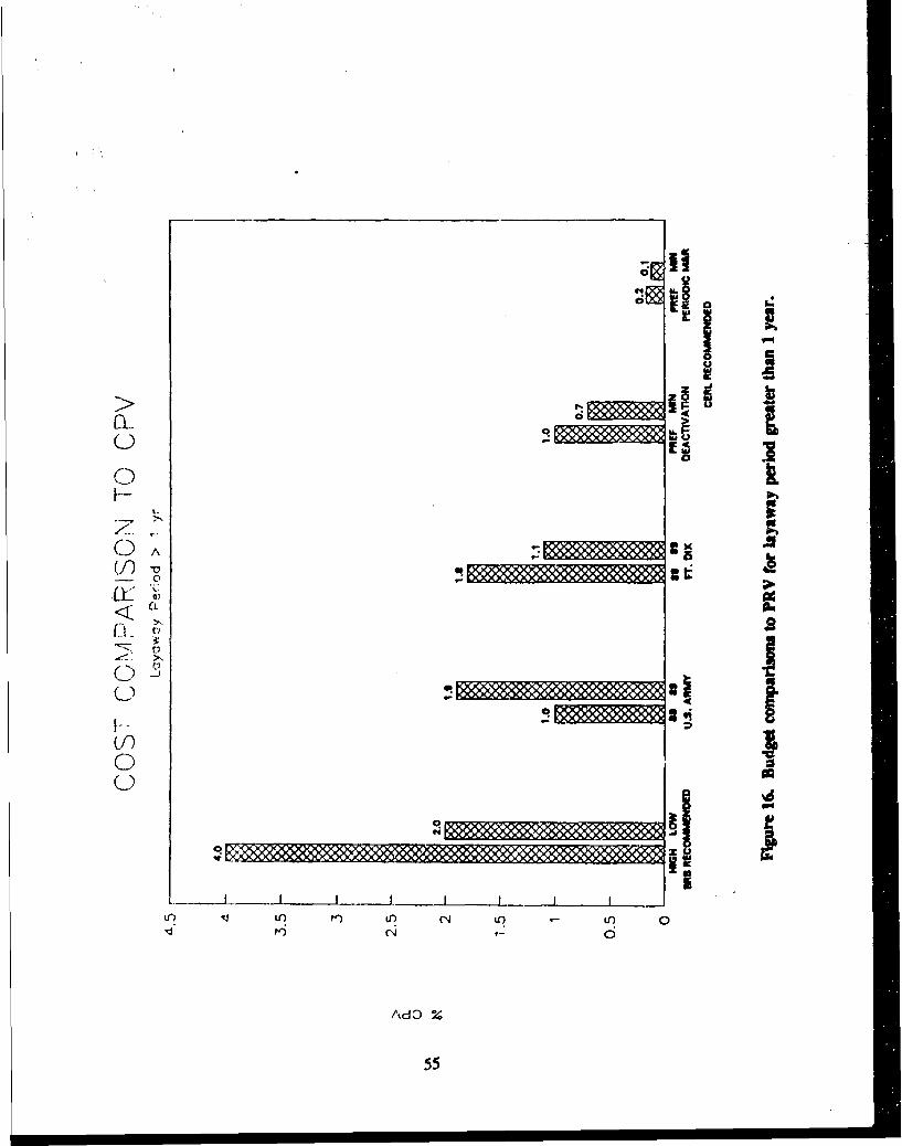
; II
as'ItS
06
mOC f
AdO

q
ft
tMEs
IA
FL. IC)C) lb
-it- *- .9ov L
tf) aCL�ci �' Au
m o U3 9-U
-C >�
C) 8I.-. I(.1-I
C) 0
(--)
II'I
in .4 in K) in (N iL�) .- in aIt) C'4 7- 6
AdD %
56

C',
I- 0Li;
(J)(A4)
4
'~- >
0) 4) - nt
Us~orin 3nLO~cX
457

SIM
01 a
-r A0 r t r
1-O--1A s8iCN3X
Li58

Several items of interest should be noted and understood from the above figures.
1. The existing expenditures for the doughboy loop are estimated assuming an equitable distributionof funds to PRV.
2. Both the deactivation and reactivation costs represent a combination of "one-time" itemsassociated with actually deactivating and reactivating a facility and routine M&R. These one-time costsare above and beyond the costs normally associated with 'K" account items and BRB guidelines.
3. The analysis for less than I-year deactivation period includes deactivation, periodic, andreactivation costs (Figures 18 and 19). Those are compared to existing annual budgets. As expected,those costs are higher than existing costs.
4. The first-year annual cost for a greater-than-l-year scenario is a total of deactivation and periodiccosts. This is lower than existing budgets for both Preferred and Minimal M&R standards.
5. The periodic (routine) M&R costs for the Preferred standard are below existing M&R costs. Aswas shown earlier, the Preferred standard is most economical in terms of life-cycle cost.
6. The periodic (routine) M&R costs for the Minimal standard are also below existing M&R costs.While use of this standard may appear attractive in terms of an annual fiscal expenditure, it is not the mosteconomical overall.
7. The Army as a whole and Fort Dix in particular historically have been underfunding M&R incomparison to the BRB recommendations.
Prioritizing M&R Requirements
A final issue that remains is the question of what should be done if the allocated M&R budgets areless than those needed for execution of a Minimal strategy. Two possibilities exist; reduce M&R orreduce facilities.
Prioritizing Facility Components and Systems
One approach for reducing M&R costs is to prioritize the various facility components and systems.When coupled to a given budget, M&R is executed in a priority fashion until the funds run out. Thisapproach really employs a concept of sub-Minimal maintenance standards. Every conceivable budget levelwould have a corresponding standard associated with it. The items listed in the appendices in VolumeII for the Minimal standard would apply, but in prioritized fashion. Tables 4 and 5 show therecommended priorities and cumulative budget requirements for deactivation and periodic M&Rrespectively. Combinations of regulatory requirements, risk, safety, accelerating effects, and level of effortwere all factors in priority determinations. The budgets assume that the Minimal M&R standard will beincorporated.
59

Table 4
Recommended Priority List for Facility Deactivation(Assumes Minimal M&R Standard)
Total Budget (in $K)
Priority D<ly D<ly D>ly D>ly(l=highest) Item R<45d R>4$d R<4Sd R>45d
1 Petroleum Products Storage 89 89 297 297
2 Boiler Plants 90 90 298 298
3 Fire Protection System 103 103 311 311
4 Steam Distribution System 197 197 405 405
5 Electrical Distribution System 247 247 454 454
6 Roofing 1280 1280 1487 1487
7 Building Exterior Closure 1297 1297 1504 1504
8 Potable Water System 1300 1300 1507 1507
9 Interior Construction 1513 1513 1720 1720
10 Refrigeration Units 2785 2785 2840 2840
11 Building Electrical 2812 2812 2867 2867
12 Gas Distribution System 2826 2826 2884 2884
13 Plumbing in Buildings 2834 2834 2894 2894
14 Heating System in Buildings 2848 2848 2911 2911
15 Air-Handier Units 2852 2852 2916 2916
16 Mess Hall Equipment 2953 2953 3017 3017
17 Wastewater System 2974 2974 3038 3038
Facility Reductions
The other possibility for executing an M&R program at reduced funding levels is to reduce thenumber of facilities. The aim of this concept is to apply no less than the Minimal M&R storidard to asmany facilities as the budget will allow.
Working With Inadequate Funding
If budget levels shrink below what is necessary to at least deactivate and periodically maintain allaffected facilities at the Minimal standard, it is recommended that the M&R activities to any facility do
60

not drop below the Minimal standard described in this report. The Minimal standard was developed asthe lower limit to which facilities should be maintained so they can retain their value and be used againin the future. Maintaining to a level below that will invite rapid deterioration (although less than Do-Nothing), and it is quite possible that the facilities may not be able to be reactivated without major repairsor reconstruction. It would be more prudent to maintain as many facilities as possible at the Minimal leveland do nothing (other than drain water lines and lock the doors) to the rest. Those Do-Nothing facilitieswould then await demolition or transfer to another user. This approach would be more prudent than tryingto equally distribute inadequate funds and perhaps lose them all. In the absence of adequate funding, thechoice of which facilities to maintain or not to maintain should be based on projected mission needs.
Table 5
Recommended Priority List for Periodic M&R(Assumes Minimal M&R Standard)
Total Budget (in $K)
Priority D<ly D<ly D>ly D>ly(1=highest) Item R<45d R>4$d R<45d R>45d
1 Petroleum Products Storage 4 4 0 0
2 Gas Distribution System 7 7 3 3
3 Fire Protection System 14 14 10 10
4 Plumbing in Buildings 17 17 13 13
5 Heating System in Buildings 18 18 16 16
6 Boiler Plants 18 18 181 131
7 Steam Distribution System 38 38 193 143
8 Electrical Distribution System 50 50 193 143
9 Roofing 50 50 268 218
10 Building Exterior Closure 50 50 272 222
11 Potable Water System 50 50 274 224
12 Refrigeration Units 50 50 274 224
13 Building Electrical 50 50 274 224
14 Air-Handler Units 50 50 282 232
15 Mess Hall Equipment 50 50 286 236
16 Interior Construction 50 50 287 237
17 Wastewater System 67 67 304 254
61

7 ENVIRONMENTAL ASPECTS AND CONSIDERATIONS
Many issues and concerns must be considered when planning or assessing the environmental impactsof facility layaway. Some of these will require further consideration and continued efforts throughout thedeactivation period of the facilities. The list below highlights the major environmental aspects ofdeactivation and some of the problems that could occur. The topics listed below are not exclusive to FortDix, and are commonly found at any Army installation that undergoes deactivation.
Major Issues
Drinking Water Taste t d Odor Problems
The prolonged reduction for water demand, triggered by a sharp decrease of population, willconsiderably enhance the potential for foul taste and odor formation within the water distribution system.This problem is addressed in more detail in the discussion of sanitary systems. In general, a distribution-flushing system (i.e., opening and flushing fire hydrants) in addition to a constant water quality monitoringprogram should provide ample latitude for operational personnel to control any taste and odor problems.
Underground Storage Tanks
Leaks of stored petroleum products from tanks within the deactivated area present a potentialproblem, One of the main guidelines for USTs calls for a thorough cleaning before deactivation.Furthermore, RCRA guidance calls for tanks 25 years or older to be tested or taken out of use by the endof 1990. Rules and regulations governing the testing procedures can be obtained from local, State, and/orFederal environmental agencies. Field personnel and contractors should be acutely aware of theprocedures for product inventory and testing for active USTs. Operational problems in spell control andvapor recovery should also be emphasized.
Asbestos Construction Materials in Existing Buildings
An important environmental threat presented by some existing buildings is the friability' of asbestosconstruction materials with time. This friable asbestos or asbestos containing material (ACM), has beenlinked to several asbestos-related diseases. In order to determine whether or not ACM is present, acomplete review, inspection, sampling, and written documentation of existing buildings must be done.Fort Dix recently conducted an asbestos survey, and its findings should be used as a baseline to assessthe environmental hazard of asbestos now and later. It was found in this survey that approximately 80percent of the asbestos in the area cited for 1ýactivation has been removed. The mechanical rooms werethe problem. Asbestos floor tiling in the doughboy area, which comprises the remaining asbestos problem,will be left intact. Some structures with asbestos problems are planned for removal and others are not.To ascertain that the areas not destined for asbestos removal are safe for reactivation, it is necessary tomonitor those areas on an ongoing basis, making sure that the constant friability of the ACM is known.Regulatory requirements (U.S. EPA, Occupational Safety and Health Administration (OSHA), State andLocal governments) for asbestos management and abatement must be heeded.
The tendency to crumnble or disintegrate under hand pressure.
62

Electric Transformers Containing PCBs
Transformers in the area of Fort Dix targeted for deactivation have been checked, and there, are noPCBs present. This will make the area much easier to reactivate. If transformers or other electricalsystem equipment is found to be filled with PCBs or PCB-contaminated oil, the EPA has specificregulations for labeling, handling, record keeping and disposal which must be followed. Compliance withall local and federal regulations regarding PCBs is mandatory.
Solid WastelHeat Recovery Facilities
The prolonged reduction in solid waste volume on the installation can adversely affect the operationand efficiency of the HRI at Fort Dix. The HRI is currently built around four rotating kilns. At presentthe solid waste volumes are sufficient to operate two or three units. Long-term plans for operating thisfacility with reduced loads and/or out-of-post wastes should be considered during the deactivation period.
Lead- and Chromate-Based Paint
The age of the buildings at Fort Dix suggests that lead might have been added to paint used there.When lead is accumulated in the body it can cause lead poisoning, which affects the brain, nervoussystem, blood, and digestive system. Environmental sources of lead contamination include paint peelingfrom walls, window sills, ceilings, floors, and banisters as well as from soil around old buildings that haveshed exterior paint over the years. A paint survey should be performed to determine the presence of leador chromate in any of the buildings to be deactivated, and what degree of primer degradation can beallowed (based on the local EPA limits).
The possible presence of lead and chromate in some of the paint currently in place was not takeninto account in estimating the M&R costs. Paints containing lead and chromate are considered hazardouswaste by the EPA, and the handling and disposal of any paint residues (i.e., chips and dust removedduring surface preparation or fall-off due to paint film breakdown or aging) may require special permitsand safety equipment. M&R of lead- or chromate-based paint systems can cost two or three times asmuch as normal paint M&R. Any metal painted surfaces that were not factory primed probably use a leador chromate primer. In addition, some factory-finished aluminum may still contain chromate.
Summary of Environmental Considerations
Certain environmental issues and concerns must be raised anytime facilities are to be laid away forpossible reactivation at a future time or if they are to be disposed. Asbestos, paint, PCBs, and USTsrepresent common areas where problems may occur. Generally, specific testing is required to determinethe extent of any suspected problem. If a problem exists, rectifying it may be very costly. This study didnot call for a sampling and testing program, but the findings from existing surveys, however, have beenincluded in the inspection and M&R checklists, costs, and budgets. However, any additional costs thatmay arise from further testing have not been included in the analysis.
63

8 SECURITY ISSUES
There are three types of threats to deactivated areas that must be considered: vandalism, vagrancy,and theft. The threat levels from vandalism are considered low to medium; the threat from vagrancy islow; and the threat from theft is considered low to medium. However, if some deactivated buildings areused to store the excess contents of other buildings, the probability of theft from those buildings may behigher.
The buildings included in this study are located in the main cantonment areas on Fort Dix. Thislocation allows easy access for the Military Police patrols that will still be needed within the area.
Minimum Measures
The key to minimizing damage or losses is to keep unauthorized individuals out of the area. Asa minimum, it is recommended that street barricades be placed on the access roads into the area to bedeactivated and signs erected designating the area off limits. Police patrols should check the buildingsfor signs of forced entry, vandalism, or vagrancy approximately three times per shift. The ladders leadingto the roof, roof hatches and openings, utility openings, and fire escapes all should be secured with anapproved locking mechanism. If material and equipment are relocated and stored in other buildings, itshould be stored in a neat, uniform manner so the guards may readily observe and detect any disarray ata glance. These measures are the most economical and should provide adequate protection of thedeactivated area.
The costs for accomplishing these measures (less security forces) are included in the budgetsdiscussed in Chapter 6.
Additional Measures
If the above measures prove ineffective, some additional protective measures that should beconsidered include, but are not limited to the following:
"* Install a fence along the outside perimeter of the area that runs parallel to the highway. This mayserve as a detenent for the casual intruder.
"* Install additional lighting around the buildings and the perimeter of the area. This measure isalso a deterring factor and promotes better visual assessment by guards.
"* Install balanced magnetic switches on the doors and windows, and motion sensors in the commonareas of the buildings. These detection measures can be tied in to the existing EMCS system,and would allow immediate notification of unauthorized entry into a building.
"* Entry through windows can be impeded permanently by replacing window glass with apenetration-resistant polycarbonate, or temporarily by covering the opening with plywood.
"• Unauthorized vehicle access can further be denied by installing a barrier cable across entryroadways.
The costs for these additional measures are not included in the budget sumnmaries addressed earlier.
64

It must be recognized that Fort Dix is an open installation and that some of the recommendationspresented above may be contrary to current policies. They are nonetheless included as examples ofpotential solutions. It should also be recognized that there can never be 100 percent security; the levelof security provided must be related to the amount of risk and loss that the installation is willing to accept.
65

9 CONCLUSV)NS AND RECOMMENDATIONS
Conclusions
The approach taken in this study was to consolidate existing technologies into a single package of
facility layaway procedures. No innovative research was attempted. In consolidating those technologiesa variety of major conclusions were made and are summarized below.
1. Both the short- and long-term layaway scenarios require scheduled M&R to combat anticipatedannual deterioration of the facilities' components. Facilities cannot simply be "locked up" until needed.Whether or not the facilities are in use, the forces of deterioration will continue to demand correctionthrough maintenance and repair.
2. Application of the procedures described in this report to installations outside the Fort Dixclimatic region should be considered with caution. These procedures were developed taking into accountthe climatic factors of central New Jersey. Deterioration modes and rates for certain distress types willdiffer in other climatic regions.
3. The decision to heat buildings or not should stem from economics. As the cost analysisrevealed, heating is not economical if the facility is properly deactivated and maintained as per therecommended guidelines.
4. Humidity control through ventilation is a much more critical parametcr than heat in minimizingbuilding interior deterioration.
5. Life-cycle cost should always be a major factor in the selection of proper layaway strategy.
6. If the Preferred procedures are carried out, the condition of facility components will be main-tained at an acceptable level of serviceability commensurate with the desired reactivation time.
7. The Minimal M&R standard provides a necessary solution and is more economical in the shortrun, but results in higher costs at reactivation. The Minimal standard was developed as the lower limitto which facilities should be maintained so that they can retain their value and be used again in the future.Maintaining to a level below that will invite rapid deterioration and the strong possibility exists that thefacilities may not be able to be reactivated without major repairs or reconstruction.
8. Policy decisions must be made about the allowed reactivation time and the length of time thatthe facilities will be laid away. These decisions are expected to be made outside the engineers' domain.They will be a product of operations planning and can pertain to certain or all facilities.
9, Both the deactivation and reactivation costs represent a combination of both "one-time" itemsassociated with actually deactivating and reactivating a facility, and routine M&R. These one-time costsare above and beyond the costs normally associated with "K" account items and the BRB guidelines.
10. The Army as a whole and Fort Dix in particular have been historically underfunding M&R asper the BRB recommendations.
66

11. Both the preferred and minimal periodic budget costs are below those recommended for activebuildings.
Recommendations
The following recommendations are made concerning facility layaway:
1. Installation personnel should follow the procedures as described.
2. The Preferred M&R standard should be used because it results in the lowest life-cycle cost tothe U.S. Army.
3. The Do-Nothing approach should not be pursued with any facility that is to be reactivated.
4. If operations guidance is lacking, all facilities should be placed in long-term layaway with a longreactivation period, because this is the most economical way to handle an underdefined layaway scenario.
5. If budget levels shrink below what is necessary to at least deactivate and periodically maintainfacilities to the Minimal maintenance standard, it is recommended that the M&R activities for any facilitynot drop below the Minimal standard provided in this report. It would be better to maintain as manyfacilities as possible at the Minimal level and let the others stand idle to await demolition or transfer thanto try to equally distribute inadequate funds and risk losing all facilities. The choice of which facilitiesshould be maintained and which should not must be made based on projected mission needs.
6. A complete condition and M&R strategy evaluation should be planned for the late 1990s to mapout the facility M&R requirements for the next decade.
7. The initiation of a periodic facility inspection program as described in Chapter 3 shouldcommence as soon as possible.
8. The procedures described in this report should be field-validated through a scientifically designedand administered field test. This test should consist of inspection and monitoring of facility componentsto determine modes and rates of deterioration. The periodic M&R and required reactivation needs shouldbe compared with those expected and the planned budgets. This test should be conducted at Fort Dix andother appropriate sites. It would constitute a portion of a Phase II effort to quantify and generalize theresults of this research.
9. A Phase II research effort should also include study of facilities and climatic regimes differentfrom those at Fort Dix. These results should then be consolidated with the findings of this study tocompile a more universally applicable methodology for facility layaway.
10. Publish the findings of this entire body of research as a Department of the Army technicalmanual.
11. The checklist procedure should be computerized incorporating a database manager. This wouldallow users the capability of extracting only the germane portions (M&R standard1, layaway period,reactivation period, system, and component) of Volume II that are specifically needed at a particular time.This would make the Volume II checklists easier to use.
67

12. The decision matrix should be computerized to facilitate universal application. Throughcomputerization, the value of each variable can be adjusted easily and analyzed through an economicanalysis model.
METRIC CONVERSION TABLE
lin. = -25.4mmSft. = 0.305m
1 psi = 6.89kPaIgal = 3.78L
"°F = (*C + 17.78) x 1.8
CITED REFERENCES
Army Regulation (AR) 210-17, Inactivation of Installations (Headquarters, Department of the Army [HQDA], January 1967).
Bailey, D.M., D.E. Brotherson, W. Tobiasson, and A. Knehans. ROOFER: An Engineered Management System (EMS) forBituminous Built-Up Roofs. USACERL Technical Report (FR) M-90/04/ADA218529 (U.3. Army Construction Engi-neering Research Laboratory [USACERL], December 1989).
Base Realignments and Closures: Report of the Defense Secretary's Commission (U.S. Department of LA'fse [DOD], December1988).
Building Research Board, Committing to the Cost of Ownership-Maintenance and Repair of Public Buildings (National AcademyPress, 1990).
The Development of Standards and the Analysis of Costs Related to the Moshballing of World War H! Facilities (HarlandBartholomew & Associates, Inc., August 1989).
Doyle, Caner, Wayne Dillner, and Myer J. Rosenfield, Handbook for Repairing Nonconventional Roofing Systems, TR M-89/04/ADA205990 (USACERL, Deccmber 1988).
Facility Engineering and Housing Annual Summary of Operations: Vol I11 (U.S. Army Engineering and Housing Support Center[USAEHSCJ, 1985).
Facility Enginee-ing and Housing Annual Summary of Operations: Vol III (USAEHSC, 1987).
Facility Engineering and Housing Annual Summary Cf Operations: Vol I11 (USAEHSC, 1988).
Facility Engineering and Housing Annual Summary of Operations: Vol I (USAEHSC, 1985).
Facility Engineering and Housing Annma" Summary of Operations: Vol III (USAEHSC, 1989).
Fisher, C.E., and T.A. Vitana, 'Temporary Window Vents in Unoccupied Histmic Buildbigs," Preservation Tech Notes (U.S.Department of the Interior, National Park Service, 1985).
Guidelines: Long-Term Layup of Fossil Plants, Final Report EPRI CS-5112 (Electric Power Rcsearch Institute, April 1987).
Hittle, D.C., R.E. O'Brien, and G.S. Percivall, Analysis of Energy Conservation Alternatives for Standard Army Buildings, TRE-183/ADA129963 (USACERL, March 1983).
Manual of Roof Maintenance and Roof Repair (National Roofing Contractors Association [NRCA] and Asphalt RoofingManufacturers Association LARMA], January 1981).
68

Meredith, D.D.. K.W. Wong, R.W. Woodhead, mid R.H. Wortinan, Design & Planning of Engineering Systems. 2nd edition(Prentice-Hall. Inc., 1985).
NAVFAC Maintenance and. Operation Manual (MQ)-300, Inactivation, Caretaker Maintenance, and Reactivation of ShoreFacilities (NAVFAC, September 1980).
NAVFAC MO-322, Inspection of Shore Facilities: Vol I (NAVFAC, July 1987).
NAVFAC MO-323, Inspection Maint enance and Operations Manualfor Naval Reserve Centers (NCR) (NAVFAC. April 1986).
Neely, E.S., R.D. Neathamnmer, and J.R. Stirn, Maintenance Resource Prediction Model (MRPM): User's Manuial, AutomaticData Processing (ADP) Report P-91/121ADA232019 (USACERL January 1991).
Preventive Maintenance Inspection-Developmeni and Implementation Guide for Facility Managers (Naval Facilities EngineeringCommand [NAVFACI - Chesapeake Divisiont, September 1990).
Shahin, M.Y., D.M. Bailey, and D.E. Brotherson, Membrane and Flashing Condition Indexes for Built-Up Roofs, Vol 1:Development of the Procedure, TR M-87/13/ADA190367 (USACERL, September 1987).
Shahir, M.Y., D.M. Bailey, and D.E. Brotherson, Memrab vne and Flashing Condition Inderes for Bailt-Up Roofs; Vol 17;Inspection and Distress Manual, TR M-87/13/ADA190368 (USACERL September 1987),
Shahin, M.Y., and J.A. Walther, Pavement Maintenance Managemnent for Roads and Streets Using the PAVER System, TR M-90P)5/ADA227464 (USACERL, July 1990).
Shahin, M.Y.. MicroPAVER Concept and Development Airport Pavement Management System, TR M-87/12/ADA187360(USACERL, July 1987).
Sliwin-ki, BTI and E. Elischer, Analysis of Facilities' Energy Use Patterns, USACERL TR E-186/ADA132527 (USACERL,August 1983).
TM 5-654, Gas Distribution Systems Operations and Maintenance Manual (HQDA,, December 1989).
U.S. Army Materiel Command (AMC)-P 235-1, Maintenance and Layaway of Government-Owned, Contractor-OperatedFacilities (AMC, July 1990).
UzaxskI, D.R., E.D. Lawson, M.Y. Shahin, and D.E. Brotherson. Development of the BUILDER Engineered Management Systemfor Building Maintenance: Initial Decision and Concept Report, TR M-90/191ADA225950 (USACERL, July 1990).
Westinghouse Electrical Maintenance Hints (Westinghouse Electric Corp., September 1976).
IJNCITED REFERENCES
American National Standard Institute (ANSI)IEEE St( 242-1986, 2nd edition, IEEE Recommiended Practice for Protection andCoordination of Industrial and Commercial Power Systems (ANSI, 1986).
ANSI/IEEE Std 493-1980, IEEE Recommended Praciice for Design of Reliable Indust~rial and ComimerCial Power Systems (ANSI,1980).
IE Informationi Notice No. 85-86: Inadequate Environmental Control for Components and Systems in Extended Storage or Layup(U.S. Nuclear Regulatory Comnmission Office of Inspection and Enforcement, 15 July 1985).
Liska, R.W., Means Facilities Maintenance Standards (R.S. Means Company, Inc., 1988).
Meier, H.W,, Construction Spci~fication~s Hlandbook, 3rd edition (Prentice-I iall Inc., 1983).
69

Prevservation, Storage and Preventive Mantenance of Seabrook II Equipment Materials & Structures, ASP-6, Revisim 2 (New
Hampshire Yankee/Seabrook Project, May 1988).
Rosen. HJ., Construction Specification Writing, Principles and Procedures, 2nd edition (John Wiley & Sons, 1981).
Technical Specification SP-1302-12-201, Revision 3. Lay-up of Mechanical Equipment For Planned Outages (GPU Nuclear
Corporation. October 1985).
The Development of Standards and the Analysis of Costs Related to the Mothballing of World War ! Facilities, Study Preliminary
Submittal (Harland Bartholomew & Associates. Inc., August 1989).
70

APPENDIX A:
FORT DIX BUILDING VENTILATION PLAN
This ventilation plan is applicable for both the Minimal and Preferred maintenance standards. Theprocedures offered below represent a minimum approach for ventilation. More elaborate procedures couldbe incorporated, but would not be as economical.
Explanation of Procedures
Each building type listed uses one of two distinct ventilation procedures:
"* Mechanical ventilation
"* Passive ventilation
Mechanical Ventilation
This approach uses the existing mechanical systems with some modifications to the control strategy.The AHU fans will be run to minimize the relative humidity within the building. The present controlsfor determining fan operation, based on interior temperature or time of day, should be replaced withcomponents that sense and compare interior and outside relative humidity. The control system will ensurethat the fan does not deliver outside air that is above 70 percent RH. The control strategy will also ensurethat the AHU is providing fresh air to the building if the inside relative humidity is above 90 percent andthe outside air is below 70 percent. For proper operation of this strategy, it is very important that theindoor humidistat be located in a space that tends to have the highest humidity within the building. Thiswill help ensure that moisture related damage to the building and its contents is minimized. Even if theoutside air is above the acceptable level for delivery to the building, it may be necessary to run the AHUto mix air within the building and to help eliminate any zones with unacceptably high humidity. Costsfor humidistats and annual electrical energy requirements for fan operation are provided in the listing foreach building type. It is imperative that the humidistats be recalibrated at least semiannually to ensurethat the system operates properly.
Mechanical ventilation is necessary when there is insufficient window area to permit installation oflouvers or where the building layout would not allow for adequate natural air flow removal of moisturefrom critical spaces. The exception is mess halls, which is discussed below.
Passive Ventilation
This approach requires the installation of louvers in strategic locations throughout the building. Thedimensions of the existing window frame openings must be field-verified before order, manufacture, andinstallation of the louv.rs.
Louvers are to placed on each floor on opposite sides of the building. All interior room doors areto be wedged in a fully opened position. Where applicable, exit stairwell fire doors are to remain in aclosed position. To calculate the number of louvers required per building, the following data were used:
71
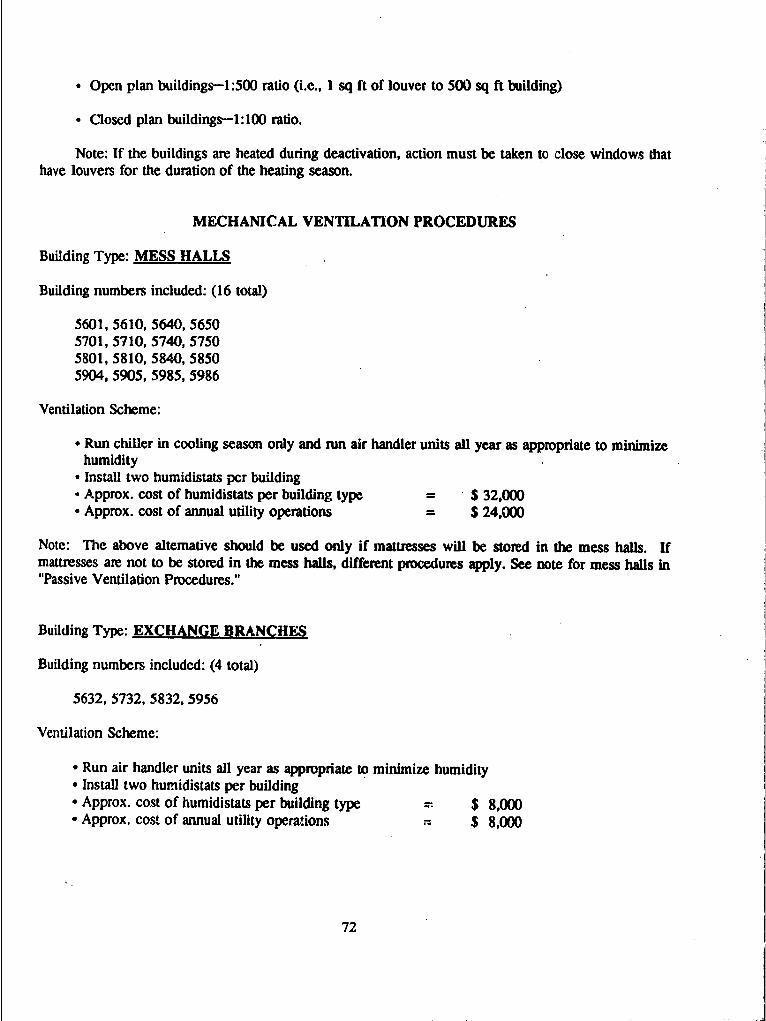
"* Open plan buildings--1:500 ratio (i.e., I sq ft of louver to 500 sq ft building)
"• Closed plan buildings-l:lO0 ratio.
Note: If the buildings are heated during deactivation, action must be taken to close windows thathave louvers for the duration of the heating season.
MECHANICAL VENTILATION PROCEDURES
Building Type: MESS HALLS
Building numbers included: (16 total)
5601, 5610, 5640, 56505701, 5710, 5740, 57505801, 5810, 5840, 58505904, 5905, 5985, 5986
Ventilation Scheme:
• Run chiller in cooling season only and run air handler units all year as appropriate to minimizehumidity
* Install two humidistats per building• Approx. cost of humidistats per building type = $ 32,000* Approx. cost of annual utility operations - $ 24,000
Note: The above alternative should be used only if mattresses will be stored in the mess halls. Ifmattresses are not to be stored in the mess halls, different procedures apply. See note for mess halls in"Passive Ventilation Procedures."
Building Type: EXCHANGE BRANCHES
Building numbers included: (4 total)
5632, 5732, 5832, 5956
Ventilation Scheme:
• Run air handler units all year as appropriate to minimize humidity• Install two hurnidistats per building• Approx. cost of humidistats per building type $ 8,000* Approx. cost of annual utility operations 7- $ 8,000
72

Building Type: RECEPTION FACILITY
Building number. 5656
Ventilation Scheme:
"* Run air handler tuits all year as appropriate to minimize humidity"* Install two humidistats"* Approx. cost of humidistats - $ 2,000* Approx. cost of annual utility operations = $ 8,000
Building Type: THEATER BUILDING
Building number: 5755
Ventilation Scheme:
"* Run air handler units all year as appropriate to minimize humidity"* Install two humidistats"* Approx. cost of humidistats t • 2,000"• Approx. cost of annual utility operations $ 9,000
PASSIVE VENTILATION PROCEDURES
Building Type: ROLLING PIN BARRACKS
Building numbers included: (43 total)
5602, 5603, 5606, 5611, 5612, 5641,5642 5645, 5646, 5651, 56525702, 5703, 5706, 5707, 5711, 5712,5741, 5742, 5745, 5751, 57525802, 5803, 5806, 5807, 5811, 5812,5841, 5842, 5845, 5851, 58525910, 5911, 5912, 5913, 5951, 5952,5989, 5990, 5991, 5992
Ventilation Scheme:
"* Number of louvers per building = 66"* Number of louvers per floor - 22"* Total number per building type - 2,838"* Approx. cost of louvers per building = $8,250"• Approx. total cost per building type = $355,000
73

Building Type: T-BARRACKS
Building numbers included. (5 total)
Building numbers not specified in study.
Ventilation Scheme:
"* Number of louvers per building - 66"* Number of louvers per floor = 20"* Number of louvers per mess hail - 6"* Total number per building type - 330"* Approx. cost of louvers per building - $8,250"* Approx. total cost per building type - $ 41,000
Building Type: MESS HALLS
Building numbers included: (16 total)
5601, 5610, 5640, 56505701, 5710, 5740, 57505801, 5810, 5840, 58505904, 5905, 5985, 5986
Ventilation Scheme:
"* Number of louvers per building - 4"• Total number per building type = 64"* Approx. cost of louvers per building = $500"* Approx. total cost per building type = $8,000
Note: This procedure should only be used if mattresses are not stored in the mess halls.
Building Type: ADMINISTRATION & SUPPLY BUILDINGS
Building numbers included: (11 total)
5604, 5643, 565357045804, 5813, 58535917, 5954, 5958, 5996
Ventilation Scheme:
"* Number of louvers per building = 4"* Total number per building type - 44
74

"• Approx. cost of louvers per building - $500"* Approx. total cost per building type = $6,000
Building Type: UNIT CHAPELS
Building numbers included: (4 total)
5635, 5735, 5835, 5950
Ventilation Scheme:
"* Number of louvers per building - 6"* Total number per building type = 24"• Approx. cost of louvers per building - $1,000"• Approx. total cost per building type = $ 4,000
Note: Two louvers shall be placed in the sanctuary and the remaining four placed in the administrativewing.
Building Type: CLINIC WITH BEDS
Building numbers included: (4 total)
5633, 5733, 5833, 5955
Ventilation Scheme:
"• Number of louvers per building = 6"* Total number per building type = 24"* Approx. cost of louvers per building = $750"* Approx. total cost per building type = $ 3,000
Building Type: CLASSROOM & BN HEADQUARTERS
Building numbers included: (12 total)
5605, 5644, 56545705, 5744, 57545805, 58545918, 5919, 5994, 5995
Ventilation Scheme:
"* Numher of louvers per building - 2"* Total number per building type = 24
75

"* Approx. cost of louvers per building = $250"* Approx. total cost per building type = $ 3,000
Building Type: REGIMENTAL HEADOUARTERS BUILDINGS
Building numbers included: (4 total)
5634, 5734, 5834, 5957
Ventilation Scheme:
"• Number of louvers per building 24"• Number of louvers per floor 8"* Total number per building type 96"* Approx. cost of louvers per building - $3,000"* Approx. total cost per building type $ 12,000
Building Type: GENERAL INSTRUCTION BUILDINGS
Building numbers included: (10 total)
5748, 6504, 6520, 6621, 6622,6741, 6749, 6884, 6896, 6898
Ventilation Scheme:
"• Approx. number of louvers per building = 5"* Total number per building type 50" Approx. cost of louvers per building (see note)"* Approx. total cost per building type = $ 6,000
Note: The 10 buildings of this building type have varying square footages. The rule of thumb to followis one louver (2 ft x 3 ft) for evt,.-y 600 sq ft of building.
Building Type: APPLIED INSTRUCTION BUILDINGS
Building numbers included: (10 total)
5720, 5924, 6510, 6523, 6555,6574, 6735, 6736, 6737, 6738
Ventilation Scheme:
"* Number of louvers (5720 & 5924) 2/bldg. 4"* Number of louvers (6510 - 6738) 2/bldg. = 16
76

"* Total number per building type = 20"* Approx. total cost per building type = $ 3,000
Building Type: BN CLASSROOM I
Building number: 5920
Ventilation Scheme:
"* Number of louvers = 4"* Approx. cost per building $1,000
Building Type: VEHICLE MAINTENANCE SHOPS
Building numbers included: (4 total)
5880, 5921, 5922, 5923
Ventilation Scheme:
"* Number of louvers per building - 2"* Total number per building type = 8"* Approx. cost of louvers per building = $500"* Approx. total cost per building type $ 2,000
Building Type: ELECTRONIC EOUIPMENT BUILDING
Building number: 6885
Ventilation Scheme:
"* Number of louvers - 4"* Approx. cost = $1,000
Building Type: GENERAL STOREHOUSE BUILDINGS
Building numbers included: (2 total)
6521, 6704
Ventilation Scheme:
"* Number of louvers per building - 2"* Total number per building type - 4
77

* Approx. cost of louvers per building $500* Approx. total cost per building type = $1,000
Building Type: DENTAL CLINIC BUILDING
Building number: 5660
Ventilation Scheme:
"* Number of louvers 16"* Approx. cost = $2,000
Building Type: PM ADMINISTRATION BUILDING
Building number: 6734
Ventilation Scheme:
"• Number of louvers 12"* Approx. cost = $2,000
Building Type: ADMINISTRATION GENERAL PURPOSE
Building numbers included: (2 total)
6518, 6608
Ventilation Scheme:
. Number of louvers per building 2- Total number per building type 4* Approx. cost of louvers per building - $250* Approx. total cost per building type $ 1,000
Building Type: GYMNASIUMS
Building numbers included: (4 total)
5631, 5731, 5831, 5953
Ventilation Scheme:
* Number of louvers per building 6* Total number per building type 24
78

* Approx. cost of louvers per building = $1,000* Approx. total cost per building type = $ 4,000
NO VENTILATION
Some buildings do not require any ventilation due to their low value. These are:
5722 Gas Station5882 Gas Station5926 Gas Station5723 Oil Storage5930 Oil Storage6897 Lavatory Building5721 Dispatch Building5887 Dispatch Building5925 Dispatch Building
79

APPENDIX B:
FORT DIX BEDDING PLAN
REACT. LAYAWAY PERIODPERIOD -
LESS THAN I YEAR GREATER THAN 1 YEAR
MINIMAL & PREFERRED: PREFERRED:All mattresses to remain in Transport all mattresses tocurrent rooms. Place designated block mess halls.individual mattressec into Remove and store dining roomstorage bags. Stack on edge tables and chairs in centralagainst wall centrally location within mess hall.located within room. Place individual mattresses
LESS into storage bags. Stack onTHAN edge no more than two
45 mattresses high.DAYS
MINIMAL:All mattresses to remainin current rooms. Placeindividual mattresses intostorage bags. Stack on edgeagainst wall centrallylocated within room.
PRIFERRED: MINIMAL & PREFERRED:Transport all mattresses to Transport all mattresses todesignated block mess halls. designated block mess halls.Remove and store dining room Remove and store dining roomtables and chairs in central tables and chairs in centrallocation within mess hall, location within mess hall,Place individual mattresses Place individual mattresses
GREATER into storage bags. Stack on into storage bags. Stack onTHAN edge no more than two edge no more than two
45 mattresses high. mattresses high.DAYS
MINIMAL:All mattresses to remain incurrent rooms. Placeindividual mattresses intostorage bags. Stack on edgeagainst wall centrallylocated within room.
80

APPENDIX C:
FORT DIX DO-NOTHING FACILITY LISTING
Cat Code Buildingi # I riotion
123-10 6739 Gas Station
872-35 6740 Dispatch Building
179-90 5717 Training Classroom Str.
730-55 5747 Waiting Shelter
214-50 5724 Grease Rack"if 5883 I
"it 5947 "
"it 5948 "
"to 5949 of
214-54 5729 Wash Platform"of 5730 "
"it 5885 "
"to 5886 "
"It 5941 o
"of 5942 "
"o 5943 of
"it 5944 to
"U; 5945 ""it 5946
81

APPENDIX D:
STEAM HEATING SYSTEM MODELING
Introduction
The steam heating system at Fort Dix consists of boiler plants located in buildings 5252, 5426, and5881, and a heat recovery incinerator (HRI) located in building 5891. All of the boilers in the boilerplants are oil-fired, and those in the HRI are fired with solid waste with natural gas used as an auxiliaryfuel. Boiler manufacturers and capacities for the boiler plants and the HRI are given in Table Dl. Thesteam distribution system is a direct-burial stece R.iewil system with supply and return lines in separateconduits. It is approximately 20 years old. Plastic condensate return lines were replaced with metalliclines in recent years. The system is not cathodically protected. In addition, there are no sump pumps in,er electrical service to, any of the approximately 60 manholes and building entry pits.
The boiler plant in building 5881 and the HRI serve the 5700, 5800, and 5900 block areas of thedoughboy loop while the boiler plants in buildings 5252 and 5426 serve the remainder of the Fort Dixhigh-pressure steam requirements (except for the laundry facility, which has its own steam generationplant. A diagram of the Fort Dix steam heating system is given in Figure D1. A project that was recentlycompleted provides a steamline link. between the 5600 and 5700 block areas of the doughboy loop.Theoretically, the entire high-pressure steam heating systeir will be interconnected so steam generated atany of the boiler plants or the HRI can be received at any location within the network. This is importantas it means that a single boiler plant may be able to supply all of thic kligh-pressure steam heatingrequirements under realignment conditions if the total demand is reduced sufficiently. The remainingboiler plants could then be deactivated to reduce required operation -and maintenance costs. Values foractual steam production, as reported in the boiler logs for each of the boiler plants and the HRI fromNovember 1988 to October 1989 ;.re given in Table D2.
Table D1
Fort Dix Boiler Information
Building Quantity Manufacturer Unit Capacity (lb/hr)
5252 3 The Bigelow Co. 40,000
5426 3 Erie City Iron Works 55,000
1 E. Keeler Co. 50,000
5881 4 E. Keeler Co. 50,000
5891 4 Energy Recovery Inc. 7,000
82

ftPaMOO MO
AptY
*400
BLOCK
BLOCKK
-/-.j
,ENA~0e~ hEWIM(RLDGW~) 310M ILOL
Fiur DI-otDxsemhaivgdsrbto yt
83*T
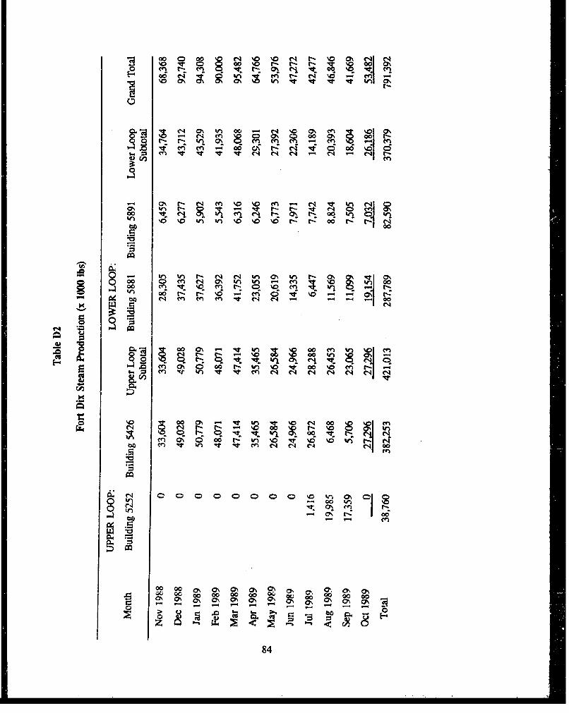
-4 00 000 N 'o 'D N t, 'o Ih NNO C) 00 %0~ r- 1- (4 0 0
00
-q 0% tn o
m'en c 00 A t- C4 "i d~ 00 c;
en %D~ enO-N (1 e 0 4V0 ;ý g 0ItrnUl
in 0 \0 'tl Il %0 MD \0 rl- o r-: 004
0 - In~ tn t- N~ C4 tn M% in - 0IoQo 00 Q en(4 0ý%n U 8 -4 M : sI 00
tn 00 t- t- \0 - n N' O %D
ba ~ ~ ~ -C-4 en m n V -40
0 000 ChW 0en ' %
"" n 0% o 0 00 oc - Wn \0 '0 \0 en rv V) 14 I CV) C1 4 C4 C
\0 0 0ý n C- 00 enC'4 ~ ~ ~ (1 -ý r- \0o
00) 00 W) 00 \0 \0 Rb 4 m 4 W) It -e -4 -4 - 1 - 0
.5i I~d484

Techdata costs database data for Fiscal Year (FY) 1989 show total expenditure for operation of alloil-fired high-pressure boiler plants (J account) to have been $4,224,310. The corresponding maintenanceexpenditures for these boiler plants (K Account) for FY 1989 was $2687. Thus the total operation andmaintenance cost for these boiler plants for FY 1989 was $4,226,997. The total steam production reportedin the Techdata database for FY 1989 was 638,126 MBtu. Thus the cost of steam production in FY 1989averaged $6.62/MBtu of steam produced. For 110 (psig) steam, this becomes $7.88/1000 lb of steamproduced. It should be noted that the figures reported in the Techdata database do not include the steamproduced and the associated expenses for the HRI, but do include the steam produced and the associatedexpenses for the two boilers at the laundry facility boiler plant (building 5324). Also, the steamproduction reported in the Techdata database is considerably lower than that reported in the boiler logsfor buildings 5252, 5426, and 5881 alone. The source of this discrepancy is unknown, but it is assumedthat the costs reported in the Techdata database are based on the same rationale as the reported steamproduction. Therefore, the figure of $7.88/1000 lb of steam produced can be used to arrive at a reasonableestimate of the cost for heating a given building once that building's steam requirements have beendetermined. It should be noted that the Techdata costs database data have been used only to obtain a unitcost for steam production. For all other purposes in this report, actual boiler log steam production datahave been used. The determination of building steam requirements for any particular building type willbe discussed in the following section.
Modeling Process
Modeling of the steam heating system allows a determination to be made of the total steamproduction requirements and the zssociated costs for a varicty of realignment scenarios. This knowledgeis important because it allows a determination to be made of the total number of boilers required to meetthe steam demand for each of these scenarios and, hence, the feasibility of deactivating individual boilerplants. It can also provide guidance on the relative merits of maintaining some degree of heat todeactivated buildings, and in the best selectinn of those buildings which are to remain occupied.
Modeling of the steam heating system is a two-step process. The first step involves the use of amicrocomputer-based program called HEAThOAD to determine the amount of steam that must bedelivered to any individual building to meet that particular building's heating requirements. Thisdetermination is made based on a number of linear regression equations that relate daily heating energyconsumption for individual building ca'wgories to the number of daily heating degree days. Theseequations were obtained as a result of a study (the Fixed Facilities Energy Consumption Investigation)performed by USACERL at several Anny installations in 1979.' The particular building categories andtheir respective linear regression equations are given in Table D3. Outputs from the HEATLOADprogram include the maximum and average heat loads (in MBtV/hr) by building category on a monthlyand an annual basis for the particular weather data used ?s input to the program. All weather data usedin modeling the Fort Dix steam heating system was obtained from the U.S. Air Force EnvironmentalTechnical Applications Center (ETAC) at Scott Air Force Base, IL, and is based on weather data fromMcGuire Air Force Base, NJ.
JB.J. Sliwinski, E. Elischer, Analysis of Facilities' Energy Use Patterns, USACERL TR E-186/ADA132527 (USACERL, August1983).
85

The second step in the steam heating system modeling process involves the use of the HEATLOADoutput as input to the Steam Heat Distribution Program (SHDP). SHDP is a microcomputer-basedpressure-flow thermal efficiency program developed through the joint efforts of the Naval CivilEngineering Laboratory (NCEL), the Naval Postgraduate School, and Oak Ridge (TN) NationalLaboratory. Its purpose is to accurately model large steam heat distribution systems. Inputs to SHDPinclude distribution line nodes, line diameters and lengths, boiler plant supply pressure, and trap leakagedata, as well as the individual building loads calculated by HEATLOAD. SHDP uses an iterative solutiortto determine the total steam output required from the boiler plant, with a breakdown of the distributionlosses and a determination of the distribution efficiency.
Before SHDP can be used with confidence to model the Fort Dix steam heating system for a varietyof realignment scenarios, it is necessary to verify the model with existing data. This has been done usingboiler log and weather data for the lower doughboy loop (5700, 5800, and 5900 blocks) for November1988 to October 1989. For the purposes of modeling the lower loop, it has been assumed that the HRIproduces 10,000 lb of steam per hour, with the remainder of the steam demand produced by the boilerplant in Building 5881. All buildings in the lower loop are assumed to be maintained at 65 F. Averagemonthly building steam requirements, as determined by HEATLOAD based on weather data for the periodNovember 1988 to October 1989, are shown in Table D4. The corresponding SHDP predictions ofmonthly steam demand and the sum of the actual monthly boiler log data for Building 5881 and the HRIare plotted in Figure D2. While there are a number of factors that can influence actual steam consumptionand demand, it can be seen from this figure that SHDP provides a reasonable approximation of the actualmonthly steam demand. When summed to provide actual and predicted steam consumption values on anannual basis, the SHDP predictions and actual boiler log data differ by less than 5 percent. It is thusassumed that HEATLOAD and SHDP may be used with confidence to provide estimates of steamproduction requirements under a variety of deactivation scenarios.
Table D3
HEATLOAD Building Categories and Energy Consumption Equations
Building Category EneMy Consumption Eauatzon
Troop Housing Barracks F. = 130.50 + (15.99 x HDDJ)
Troop Housing Barracks (after 1966) E4 = 81.91 + ( 7,40 x HDDd)
Troop Housing Barracks (modular) F = 295.90 + (34.21 x HDDd)
Dining Facilities E_4 = 231.80 + (12.42 x HDDd)
Family Housing E = 105.60 + (20.02 x HDD4)
Administration/Training Eh = 76.71 + (18.97 x HDD4)
Mcdical/Dcntal E4 = 254.40 + (24.31 x HDDd)
Storage Eh = 35.70 + (36.10 x HDDd)
Production/Maintenancc Eh = 138.40 + (35.73 x HDDI)
Fieldhouses/Gymnasiums Eh = 73.69 + (32.40 x HDDd)
where Eb = Daily Heating Energy
and HDDd = Daily Heating Degree Days
86

4Ctor- on ev f-.knh- 4 wW f- en Ce w-n 10& in in r ma a &- win 04 inca
4w i
CL . - x.
~ a.in in r Inn in - o "A in w a - v in i nme - r-s wn inn n-Cd. .d . .in in . . in . . . 4.0.
en
w a 45In 0m r c m-nmnn-uu u--u cm. in a% 44r T=4 n at a
-,cj e "c ý. 0Inr l r4 rt iý G n ftr
45(4
42 C ' 4 In iP rcn 4D0 04 - -en
.. ,E _ 4 In -f ipm4 mZn n w 04 cma t% n w - -
p.- M-m4 z-0
~ outr-a v Cinina -. 4- in i nu naC nt ni
t4 Wl4.i Wir .4 N n .-i
000 4 Awe in a' in e" in wia in n mw' Cd c4tCN
in u n O. a% P4 u--n a -r - C-
4A in 04 c ý,%ow" r- -4 cn v 044ý Soo a41j in Nr i e - -
in~~~I caxr In-a cm
to N4- 0t an nec u-c GD no -c -a a u.40nSti ~
wD w~m -w = in -IDS m Cd
i~rn at -mr-n i4n~ e - 0eru cm -n u-e to oi tCew, a -4. .- C 0-4 .-.- vda ~oai '4 %o.. 4
'lil .. - ý r.r ý
".. a, C y m ft au, r- - -in0 0 - tti 4.Z-a in - in q in c, to 0404 C t-
4~~,-i~ in am - C n t u i- - min a- e - mcrft ~ ~ ~ ~ ~ ~ I Cd o- .-.. i -n Ingr 4 .. 4 e e C,
w)4 to W I
p.- '87

0
I�i�* 4 4 - --* 4 4 4 4 4* 4 4 4 4
* 4 4 S 4 4* 4 4 4 S -�
* 4 4 4 4 Id
* 4 4 4 4'. 4* 4 4 4 4 . 4 4
* S 4 4 * 4 4* 4 5 4 4 4 4 4
* S 4 4 * S S* 4 4 4 4 44 4 4
* 4 4 4 4 5 5* 4 4 4 4 4 4 4
* 4 4 4 4 4 4* 4 0 4 5 4* 4 4 4 4 4 4
* 4 4 4 4 4 4 4* 4 5 5 4 4 4* 5 4 4 4 4 4 4
* 4 4 4 4 4 4* 4 4 4 4 4 5 4* 4 4 4 4 4 4 4* 4 4 4 4 4 4* 4 4 4 S ** 4 * ' 4 4 4* 4 4 4 5 4 4* 4 4 4 4 4 5 4* 4 4 4 4 4 4 4 r�.* 4 4 4 4 4 4 4* 4 4 4 4 4 5 4* 4 4 4 4 4 4 4
* 4 A 4 4 5 4
* 5 4 4 4 5 £ 4�.* 4 4 S 4 4 4 =* A 4 5 4 .4 4 5 47* 4 4 A 4* 4 4 4 4 * 4 0* 4 4 4 4 4 A .* 4 4 4 4 4 4* 4 4 4 4 4 5* S 4 4 4 4 4
* S S *A e 4 44 4 4
* 4A A.
* 2
* 2 1* I
44 4 4* 5 4 4 4 4
'S 4 5 4 44 4 4 4
* 4 4 4* 4 4 4
A * 4 5 4�4 4 4 45 4 4 5* 4 0
* 4 4
* 4* 4* 5* 5 54� S
4�*4.4.
* 4 4* 4 4 4* 4 4 4* 4 4 4
4 4 4* 2 1 ** 4
A I A I(sqp�) pt3O'j we�j�
88
Modeling Scenarios
As a means of facilitating the modeling of the various deactivation scenarios and the interpretationof the results, the Fort Dix steam heating system was broken down into six separate steam loops that wereanalyzed individually. The interdependence of the various loops was preserved in the SHDP models. Theindividual loop designators and the corresponding Fort Dix areas are as follows: Loop A - 5900 block;Loop B - 5800 block; Loop C - 5700 block; Loop D - 5600 block; Loop E - 5500 block; and Loop F -5200 and 5400 blocks. Current understanding of the Fort Dix realignment plans calls for no buildingsto remain occupied in Loop A and only a very few buildings in Loops B, C, and D to remain occupied.There is a possibility that some of the T-barracks in Loops E and F may be deactivated as well, althoughno definite plans exist at this time. Fcr modeling purposes, it is assumed that the lower doughboy loop(Loops A, B, and C) is served by the HRI at 10,000 lb steam per hour with the remainder of the steamdemand supplied by the boiler plant in Building 5881. It is assumed that the upper doughboy loop (LoopsD, E, and F) is supplied steam from the central boiler plant in Building 5426. The boiler plant in Building5252 (the Hospital Boiler Plant) was not considered in the modeling process as it currently produces onlya small amount of the total steam used by the upper dougnboy loop and is not used concurrently with thecentral boiler plant in building 5426.
Buildings in the doughboy loop are modeled as being heated to 65 TF(normal occupied status),heated to 45 *F(heated unoccupied status), or not heated. All HEATLOAD steam supply requirementsfor the deactivation scenarios are based on 30-year average weather data. The average and maximumannual steam demand by building category as determined by HEATLOAD for the 30-year average weatherdata are given in Table D5 for a 65 OF base temperature and in Table D6 for a 45 OF base temperature.It might be noted that this data can be used to estimate the costs of heating any individual building type.As an example, consider a rolling pin barracks (pre-1966). HEATLOAD predicts an average annual steamdemand of 501.7 lb/hr for heating to 65 oF(Table D5). Over a year this comes to a total demand of4,394,892 lb steam. Using the figure previously quoted for steam cost ($7.88 per 1000 lb steam) providesfor an annual cost of approximately $34,630. This figure represents the cost for the steam actually usedby the building. The amount of steam required from the boiler plant to satisfy the steam demand of anindividual rolling pin barracks will be greater than the building demand by a factor inversely proportionalto the distribution efficiency. Distribution efficiencies for the realignment scenarios modeled here rangefrom approximately 13 percent to 51 percent. Hence the total estimated cost for heating a single rollingpin barracks to 65 OF ranges from approximately $67,900 to $266,380.
A total of eight different deactivation scenarios have been modeled. The conditions for thesedifferent realignment scenarios are as follows:
"* Scenario I - All buildings in all loops are heated to 65 TF. Individual building steamdemands are given by the HEATLOAD average annual demands. This scenario is indicativeof normal current operation and is provided as a basis for comparison with the otherscenarios.
" Scenario 2 - All buildings in all loops are heated to 45 TF. Individual building steamdemands are given by the HEATLOAD average annual demands. The use of the 45 *F build-ing temperature for the E and F loops is intended to provide some approximation to theprobability that some of these buildings may be deactivated while the majority will remainoccupied. At this time there is not sufficient knowledge of the realignment plans for thesetwo loops to make more a precise estimate of steam demand in these areas.
89

Table DS
Fort Dix Steam Demand (65 *F Base Temperature)*
Average Maximumlb/hr Steam lb/hr Steam
Building Type Sq Ft (@ 120 psia) (@120 psla)
Mess Hall 11,323 207.6 722.7Barrarcks (Pre-1966) 40,653 501.7 1415.1Adniin HQ 9,840 116.8 379.0Admin/Storage 12,194 145.4 469.7Motor Pool 4,787 105.9 346.2Gym 20,648 427.7 1132.8Dispensary 3,707 52.1 116.8Px 4,800 89.9 333.6Brig HQ 6,137 73.1 237.0Chapel 7,762 92.4 299.2Dental Clinic 10,875 153.8 343.7Theater 17,437 361.3 957.1Child Care/EMSC 27,578 327.7 1063.0Reception Center 131,000 1558.8 5050.4Bldg 5219 5,338 63.9 205.9Bldg 5240 31,130 644.5 1708.4Hospital 427,165 6043.7 13498.3Bldg 5256 15,486 190.8 538.7Bldg 5257 11,360 140.3 395.0Bldg 5275 27,137 175.6 457.1Bldg 5407 2,578 31.1 99.2Bldg 5408 3,800 45.4 146.2Bldg 5411 30,479 363.0 1174.8Bldg 5418 97,838 1163.9 3772.3Bldg 5429 4,640 65.5 146.2Bldg 5441 39,770 490.8 1384.0Bldg 5513 9,230 110.1 355.5Bldg 5523 29,758 353.8 1147.1T-Type Barracks 39,770 481.5 1377.3
"ýBased on 30..year average weather data.
90

Table D6
Fort Dix Steam Demand (45 *F Base Temperature)*
Average Maximum
lb/hr Steam lb/hr SteamBuilding Type Sq Ft (@ 120 psia) (@ 120 psla)
Mess Hall 11,323 142.0 465.5Barracks (Pre-1966) 40,653 385.7 959.7Admin HQ 9,840 84.0 248.7Admin/Storage 12,194 104.2 308.4Motor Pool 4,787 75.6 226.9Gym 20,648 338.7 781.5Dispensary 3,707 44.5 84.9Px 4,800 59.7 212.6Brig HQ 6,137 52.1 155.5Chapel 7,762 66.4 195.8Dental Clinic 10,875 130.3 248.7Theater 17,437 285.7 659.7Child Care/EMSC 27,578 235.3 696.6Reception Center 131,000 1116.8 3310.1Bldg 5219 5,338 45.4 135.3Bldg 5240 31,130 510.1 1178.2Hospital 427,165 5100.0 9783.2Bldg 5256 15,486 147.1 365.5Bldg 5257 11,360 107.6 268.1Bldg 5275 27,137 139.5 316.8Bldg 5407 2,578 21.8 65.5Bldg 5408 3,800 32.8 95.8Bldg 5411 30,479 259.7 770.6Bldg 5418 97,838 834.5 2472.3Bldg 5429 4,640 55.5 105.9Bldg 5441 39,770 377.3 938.7Bldg 5513 9,230 79.0 233.6Bldg 5523 29,758 253.8 752.1T-Type Barracks 39,770 376.5 934.5
"Based on 30-year average weather data.
91

"* Scenario 3 - All unoccupied buildings in Loops A, B, C, and D are heated to 45 OF. Allother buildings in these loops and all the buildings in Loops E and F are heated to 65 OF.Individual building steam demands are given by the HEATLOAD average annual demands.
"* Scenario 4 - All unoccupied buildings in Loops A, B, C, and D are unheated. All otherbuildings in these loops and all the buildings in Loops E and F are heated to 65 TF.Individual building steam demands are given by the HEATLOAD average annual demands.
Scenario 5 - Same cenditions as Scenario I except that individual building steam demandsare given by the HEATLOAD maximum annual demands.
"* Scenario 6 - Same conditions as Scenario 2 except that individual building steam demandsare given by the HEATLOAD maximum annual demands.
"* Scenario 7 - Same conditions as Scenario 3 except that individual building steam demandsare given by the HEATLOAD maximum annual demands.
Scenario 8 - Same conditions as Scenario 4 except that individual building steam demandsare given by the HEATLOAD maximum annual demands.
Modeling Results
Total steam requirements and individual loop steam requirements (in pounds of steam per hour), andthe associated annual costs (based on $7.88 per 1000 lb steam), are shown in Tables D7 through D14 foreach of the eight scenarios modeled. Additional scenarios can be approximated from this data bysumming individual loop totals from the appropriate existing scenarios. As an example, to approximatethe annual average steam production requirements for a scenario in which all unoccupied buildings inLoops A, B, C, and D are unheated, all occupied buildings in these loops and all buildings in Loop F ameheated to 65 OF, and all buildings in Loop E are heated to 45 *F, one need simply add the Loop E resultsfrom Scenario 2 to the results of Loojis A, B, C, D, and F from Scenario 4.
As can be seen from the results given in Tables D7 through D14, the total steam demand could bemet for all cases (with the exception of Scenario 5) by the central boiler plant (Building 5426) alone,provided that the ongoing project to link the 5600 and 5700 block areas is completed. Scenario 5corresponds to a maximum load condition with all buildings being occupied, and as such, is not pertinentto any realistic realignment scenario. A more realistic realignment scenario would produce a total steamdemand ranging from the conditions of Scenario 4 (66,869 lb/hr) to the conditions of Scenario 8 (112,450lb/hr). Under these conditions, the total steam demand could be met by steady use of two boilers in thecentral boiler plant with a third boiler on standby for peak load conditions.
It should be noted that the distribution efficiency of a steam heating distribution system depends notonly on the distance the steam must travel to reach the load, but also on the density of the load in the areabeing served. To illustrate this point, consider the difference in lower doughboy loop steam distributionefficiencies between Scenario 1 and Scenario 4. In Scenario I all buildings are heated to 65 OF. SHDPgives a value of steam distribution efficiency of 50.7 percent under these conditions. That is, for every100 lb of steam produced by the boiler plant, 50.7 lb is actually used to satisfy the heating requirements.The energy contained in the remaining 49.3 lb is lost within the distribution system. In Scenario 4, only
92

Table D7
SHDP Annual Steam Demand and Cost, Scenario 1
Steam DemandLoop (lb/hr) Cost ($)
A 14,727 1,016,587B 14,349 990,494C 18,594 1,283,522D 17,448 1,204,415E 15,220 1,050,618F 26.401 1.822.429
TOTAL 106,739 7,368A;65
Table D8
SHDP Annual Steam Demand and Cost, Scenario 2
Steam DemandLoop (lb/hr) Cost ($)
A 12,758 880,669B 12,183 840,978C 16,574 1,144,083D 15,091 1,041,714E 12,771 881,567F 231224 1.603.125
TOTAL 92,601 6,392,136
Table D9
SHDP Annual Steam Demand and Cost, Scenario 3
Steam DemandLoop (lb/hr) Cost ($)
A 12,758 880,669B 12,381 854,646C 16,728 1,154,714D 15,164 1,046,753E 15,220 1,050,618F 2AQJ 1.822.429
TOTAL 98.652 6,809,829
93

Table DIO
SHDP Annual Steam Demand and Cost, Scenario 4
Steam DemandLoop (lb/hr) Cost ($)
A 0 0B 6,260 432,120C 10,962 756,694D 8,026 554,025E 15,220 1,050,618F 26.401 1,822,429
TOTAL 66,869 4,615,886
Table D1I
SHDP Annual Steam Demand and Cost, Scenario 5
Steam DemandLoop (lb/hr) Cost ($)
A 30,189 2,083,910B 31,346 2,163,777C 34,386 2,373,624D 26,717 1,844,242E 33,300 2,298,659F 50.524 3,487.611
TOTAL 206,462 14,251,823
Table D12
SIIDP Annual Steam Demand and Cost, Scenario 6
Steam DemandLoop (lb/hr) Cost ($)
A 22,508 1,553,700B 22,898 1,580,621C 26,549 1,832,646D 26,717 1,844,242E 24,360 1,681,542F 39.215 2,706.964
TOTAL 162,247 11,199,715
94

Table D13
SHDP Annual Steam Demand and Cost, Senarlo 7
Steam DemandLoop (lb/hr) Cost ($)
A 22,508 1,553,700B 23,671 1,633,981C 27,149 1,874,063D 27,004 1,864,054E 33,300 2,298,659F -0ý524 3,487,611
TOTAL 184,156 12,712,068
Table D14
SHDP Annual Steam Demand and Cost, Scenario 8
Steam DemandLoop (lb/hr) Cost ($)
A 0 0B 7,831 540,565C 12,185 841,116D 8,610 594,338E 33,300 2,298,659F 50.524 3.487.611
TOTAL 112,450 7,762,289
the few buildings remaining occupied in the lower doughboy loop are heated to 65 OF. The remainingbuildings in the lower doughboy loop arc unheated. Hence, the load density (i.e., the number of heatedbuildings in the given area) is considerably lower than in Scenario 1. The lower doughboy loop steamdistribution efficiency for Scenario 4 is given by SHDP to be 12.8 percent. That is, for every 100 lb ofsteam produced by the boiler plant, only 12.8 lb is actually used to satisfy the heating requirements. Theenergy contained in the remaining 87.2 lb is lost within the distribution system. Thus it is advisable toposition the heating load as close as possible to the steam source, and to provide the greatest load densityas possible.
Steam Heating System Recommendations
It is recommended that the basic realignment heating scenario correspond to that of Scenario 4.That is, no hcat is to be provided to UDOCcupied buildings. It is also recommended that the ongoingproject to provide a steamline link between the 5600 and 5700 block areas of the doughboy loop becompleted as soon as possible. This will allow all steam heating demands to be met by the central boiler
95

plant. It is recommended that all boilers in buildings 5252 and 5881 be placed in a dry layup status asdescribed in Chapter 5 under "Boiler Plants." Also, one boiler in the central heating plant (Building 5426)should be placed in dry layup. The particular boiler in the central heating plant to be layed up in a drystatus should be the one in the worst condition. Two of the boilers in the central heating plant should bekept in active use. The remaining boiler may be kept in a standby status to meet peak load requirements.This may be accomplished by circulating treated feedwater heated in a tube-in-shell heat exchanger bysteam drawn from one of the active boiiers. The requisite plumbing modifications and associated costswill depend on the particular physical layout and features of the particular boilers involved. This servesthe purpose of preventing corrosion in the standby boiler as well as keeping the boiler refractory warmto prevent refractory damage due to thermal stresses when the boiler is brought on line. The three boilersnot in dry layup should be rotated on an annual basis so no boiler remains in standby status for more than1 year at a time. Since the total steam demand can be met by the central boiler plant, there is no needfor steam to be produced by the HRI. It could be placed in dry layup as far as steam demand isconcerned. If it is deemed necessary to maintain operation of the HRI to meet community solid wastemanagement needs, then it is recommended that a steamline link be provided between the 5900 and 5200blocks. This would shorten the distance that the steam produced at the HRI would have to travel to reacha heating load, and thus would increase the steam distribution efficiency.
Long-range (1993-1994) Fort Dix realignment plans call for the activities left on the doughboy loopto be moved north of 8th Street. This would decrease the distance from the central heating plant to thethermal load that these activities present. and would place them in a higher heating-load-density area.These two effects would serve to greatly increase overall steam distribution efficiency. In the interim,thought should be given to moving these activities as close as possible to the central heating plant,possibly by consolidating them in the 5600 block area. Installation of stand-alone heating units in thosefew buildings remaining open is not considered a feasible option given the relatively short time before theactivities associated with these buildings move north of 8th street.
96

APPENDIX E:
PROCEDURE FOR COMPUTING COSTS FOR STEAM DISTRIBUTION SYSTEM
Since pipe sizes and numbers of manholes will vary throughout the system, the cost per linear footmay vary throughout the system. To develop costs for specific sections of the steam distribution system:
1. Determine the number of manholes (N) and number of linear feet of piping (L), including supplyand return in the section to be analyzed.
2. Decide which criteria to use. For Preferred Warm/Hot, use Table El. For Preferred Cold, useTable E2. For Minimal Warm/Hot, use Table E3. For Minimal Cold, use Table E4.
3. Follow the table to calculate costs for deactivation, periodic M&R, and reactivation procedures.
97

Table El
Costs for Preferred Warm/Hot SteamDistribution System Procedures
Variables used:
N = Number of manholes in section to be analyzedL = Number of linear feet of piping (incl. supply and return) in section to be analyzedRC = Replacement cost of section of system (from Table E5)
DEACTIVATION
ACTIVITY N OR % ACTIVITY TOTALL FACTOR COST(S) COST
Manhole Inspection N * 1.0 * 175.00 =Lab/pressure tests N * 1/10 * 300.00 =Install power & pumps N * 1.0 * 1200.00 =Replace gaskets/packing N * 1/3 * 100.00 =Replace corr. internals N * 1/6 * 150.00 =fiCaulk wall penetrations N * 1/3 * 40.00 =Repair pipe/casing leak N * 1/15 * 3000.M'; =Replace conduit system 0.0025 * RC =
TOTAL DEACTIVATIONCOST (ADD UP THE =ABOVE COSTS)
PERIODIC M&R (ANNUAL COST)
ACTIVITY N OR % ACTIVITY TOTALL FACTOR COST ($) COST
Manhole Inspection 4N * 1.0 * 40.00 =(4x per year)
Incidental M&R 4N * 1/10 * 100.00 =
TOTAL PERIODICCOST (ADD UP THE =ABOVE COSTS)
REACTIVATION COST $0.00
98

Table E2
Costs for Preferred ColdSteam Distribution System Procedures
Variables used:
N = Number of manholes in section to be analyzedL - Number of linear feet of piping (incl. supply and return) in section to be analyzedRC = Replacement cost of section of system (from Table E5)
DEACTIVATION
ACTIVITY N OR % ACTIVITY TOTALL FACTOR COST COST
Manhole Inspection N * 1.0 * 175.00 =Lab/pressure tests N * 1/10 * 300.00 =Install power & pumps N * 1.0 * 1200.00 =Replace gaskets/packing N * 1/3 * 100.00 =Replace cerr. internals N * 1/6 * 150.00 =Caulk wall penetrations N * 1/3 * 40.00 =Repair pipe/casing leak N * 1/15 * 3000.00 =Replace conduit system 0.0025 * RC =Shut down/drain lines L * 1.0 * 0.0375 =
TOTAL DEACTIVATIONCOST (ADD UP THE =ABOVE COSTS)
PERIODIC M&R (ANNUAL COST)
ACTIVITY N OR % ACTIVITY TOTALL FACTOR COST COST
Manhole Inspection 4N * 1.0 20.00 =Incidental M&R 4N * 1/30 * 100.00 =
TOTAL PERIODICCOST (ADD UP THE =ABOVE COSTS)
REACTIVATION COST = L * $0.0625
99

Table E3
Costs for Minimal Warm/HotSteam Distribution System Procedures
Variables used:
N = Number of manholes in section to be analyzedL = Number of linear feet of piping (incl. supply and return) in section to be analyzedRC = Replacement cost of section of system (from Table E5)
DEACTIVATION
ACTIVITY N OR % ACTIVITY TOTALL FACTOR COST ($) COST
Manhole Inspection N 1.0 * 100.00 =Replace gaskets/packing N * 1/3 * 100.00 =Replace corr. internals N * 1/6 * 150.00 =
TOTAL DEACTIVATIONCOST (ADD UP THE ffiABOVE COSTS)
PERIODIC M&R (ANNUAL COST)
ACTIVITY N OR % ACTIVITY TOTALL FACTOR COST(S) COST
Manhole Inspection 2N * 1.0 * 40.00 =(2X per year)
Incidental M&R 2N * 1/10 * 100.00 =
TOTAL PERIODICCOST (ADD UP THE =ABOVE COSTS)
REACTIVATION COST = RC * 0,025
100

Table E4
Costs for Minimal ColdSteam Distribution System Procedures
Variables used:
N = Number of manholes in section to be analyzedL = Number of linear feet of piping (incl. supply and return) in section to be analyzedRC = Replacement cost of section of system (from Table E5)
DEACTIVATION
N OR % ACTIVITY TOTALL FACTOR COST($) COST
Manhole Inspection N * 1.0 * 100.00 =Replace gaskets/packing N * 1/3 * 100.00 =Replace corr. internals N * 1/6 * 150.00 =Shut down/ drain lines L * 1.0 * 0.0375 =
TOTAL DEACTIVATIONCOST (ADD UP THE =ABOVE COSTS)
PERIODIC M&R (ANNUAL COST)
ACTIVITY N OR % ACTIVITY TOTALL FACTOR COST ($) COST
Manhole Inspection 2N * 1.0 * 40.00 =(2x per year)
Incidental M&R 2N * 1/30 * 100.00 =
TOTAL PERIODICCOST (ADD UP THE =ABOVE COSTS)
REACTIVATION COST = RC * 0.10
101
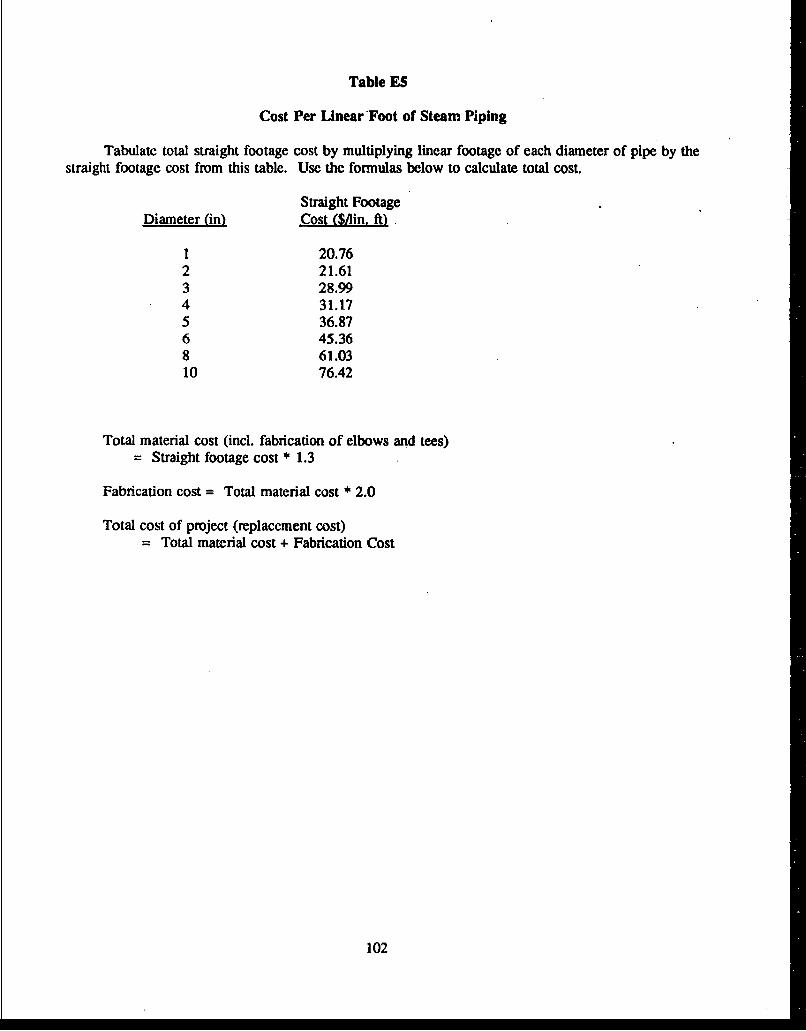
Table ES
Cost Per Linear Foot of Steam Piping
Tabulate total straight footage cost by multiplying linear footage of each diameter of pipe by thestraight footage cost from this table. Use the formulas below to calculate total cost.
Straight FootageDiameter (in) Cost (SAin, ft)
1 20.762 21.613 28.994 31.175 36.876 45.368 61.0310 76.42
Total material cost (incl. fabrication of elbows and tees)
= Straight footage cost * 1.3
Fabrication cost = Total material cost * 2.0
Total cost of project (replacement cost)= Total material cost + Fabrication Cost
102

APPENDIX F:
UST COSTS
Table F1
UST Closure Costs
Temporary closure: --------------------------------------------------------------------------------- $3000-$6000
Includes tank emptying, cleaning, capping lines, and periodic inspection.
Permanent closure - in place: --------------------------------------------------------------- $10,000-$20,000
Includes $2000-$5000 for construction management, removal of product, excavation to top of tank,disconnection and removal of associated tank lines, capping and isolation of associated equipment, tankcleaning, filling with inert material, restoration of tank area, and periodic inspection.
Permanent closure - tank removal: ------------------------------------------------------- $10,000-$20,000
Includes $2000-$5000 for construction management, removal of product, disconnection and removal ofassociated tank lines, tank cleaning, rinsing, tank excavation and removal, tank transport and disposal,backfilling and restoration of tank area.
Small Tank Closing: ------------------------------------------------------------------------------- $4000-$8000.This cost applies to small capacity USTs (1000 gallons or less), whether left in place or removed.
103

Table F2
Costs for UST Closure-Related Field Work
Hydrogeologic site study: -------------------------------------------------------------------------- $1000-$2000
Includes $50-$100/hour for a hydrologist. The higher rates are expected for a more experienced or
certified professional.
Preliminary investigation of suspected leak ------------------------------------------------- $4000-$10,000
Includes $150-$200/hour for backhoe and operator, $2000-$2500/day for excavation equipment withoperators, $1000-$1500/day for drilling equipment, and $50-$100/hour for management.
Testing tank integrity ------------------------------------------------------------------------------- $2000-$3000
Includes $40-$70/hour for engineering oversight, $900-$1500/day for test contractors, $300-$800 per tanktest, $75-$150 per line test and leak detector test.
104

Table F3
UST Installation-Related Costs
Tank Cost:
Single-walled steel tank, asphalt-
and epoxy-coated with sacrificial anodes --------------------------------------------------------- $3000-$4500
Single-wallcd steel tank, fiberglass-coated ------------------------------------------------------ $6000-$7000
Single-walled fiberglass reinforced plastic ------------------------------------------------------- $5500-$7000
The price of a double-walled tank is approximately 90 - 100 percent more than the cost of a single-walledtank.
Installation:
Includes handling, excavation, testing for leaks,anchoring when necessary, bedding and backfilling,piping connections, monitoring, and cathodicprotection systems, etc.----------------------------------------------------------------------------- $5000-$8000
Cost of Other Items:
Sensor system, between-wall tank/pipe --------------------------------------------------------------- $400-$1800
Electronic inventory control for multiple tanks -------------------------------------------------- $4500-$7500
Contractor-supplied tank test -------------------------------------------------------------------------- $400-$1300
Drilling cost for each monitoring well ---------------------------------------------------------------- $400-$700
Electronic monitoring system for wells ------------------------------------------------------------- $900-$1200
Electronic gas and petroleum sensor for well ------------------------------------------------------- $700-$2500
105

APPENDIX G:
FORT DIX UST ISSUES
Affected Tanks
The Fort Dix petroleum products storage system consists of a number of aboveground and under-ground storage tanks of various sizes holding several fiuel types, including No. 2 and No. 6 fuel oil,gasoline, and diesel fuel. A listing of the petroleum products storage tanks in the area affected by therealignment is given in Table G1. These tanks are either associated directly with a building scheduledfor deactivation or are associated with a boiler plant that may be deactivated due to reduced steam heatingdemand under various realignment scenarios. Tanks listed in Table GI having an ID number beginningwith the letter "A" afe currently not in use, whereas tanks having an ID number beginning with the letter"E" are currently in use. Tanks whose ID number contains a number following the "A" or "E" (firstcharacter) refer to UST for which information is contained in the USACERL UST survey database. Theseare, in general, large UST having capacities greater than 1000 gallons.
As can be seen from the ID number information in Table G1, data is available in the USACERLUST database for 13 of the UST in the affected area. According to the database, all of these tanks aremade of steel and are of single-wall construction. All of them are painted externally and some of the themare lined internally. The leak potential index (LPI) ratings for these tanks range from 2.5 to 3.2, placingthem all in the medium-potential-for-leakage category. The tanks range from 18 to 49 years old. Ten ofthese tanks are currently in use. Tank A71 has not been used since 1975 and apparently still containsabout 305 gallons of motor gasoline (MOGAS). The other two inactive tanks, A57 and A72, have beenempty since 1981 and 1975, respectively.
Cost of UST Closure
According to the New Jersey Department of Enviroranental Protection (NJDEP), tank decommission-ing costs range from $4000 to $9000, while costs for tank site assessment vary from $2000 to $10,000.Since these figures are compatible with the cost ranges given in Appendix F, the tank closure costs forFort Dix have been based on the figures in Table Fl.
These costs do not irnclude environmental cleanup costs, which are estimated to be about $50,000to over $1,000,000 per tank site, depending on the site's contamination complexity.
Discussion in this section will be limited to the 13 large USTs in the affected area for which dataexist in the USACERL UST database.
Tank size and the number of tanks at a site are important factors in determining closure cost. Largertanks cost more to close in general than do smaller ones. Also, if a site contains more than one tank, thecost for closure on a per-tank basis is less than for a single tank site. Tanks A71 and A72, and tanks E38,E39, and E40, are located at buildings 6739 and 5252, respectively. The other eight tanks are located atindividual sites. Therefore, a total of 10 UST sites must be evaluated.
As can be seen froin Table Fl, the cost for permanent closure of a 10,000 gallon tank located ona single-tank site ranges from $10,000 to $20,000. A tank with a capacity less than 10,000 gallons (butgreater than 1000 gallons) should cost somewhat less than this range. To account for this difference, a
106

Table GI
Affected Petro, leum Products Storage Tanks
Location Above/Underground ID Number Contents Capacity
5252-1 Underground E38 #6 Fuel Oil 25,0005252-2 Underground E39 #6 Fuel Oil 25,0005252-3 Underground E40 #6 Fuel Oil 25,0005426-1 Aboveground E-#6 Fuel Oil 760.0005426-2 Aboveground E-- #6 Fuel Oil 300.0005706 Underground E56 Diesel Fuel 2,0005720 Underground A57 Gasoline 5,0005876-1 Aboveground E-- #2 Fuel Oil 2755876-2 Aboveground E-- #2 Fuel Oil 2755876.3 Aboveground E-- #2 Fuel Oil 5505880 Underground E58 Unleaded Gas 5,0005881 Underground E59 Diesel Fuel 5.0005881 Aboveground E-- 46 Fuel Oil 300.0005882 Underground E60 Gasoline 5,0005901 Underground E61 #2 Fuel Oil 6,0005920-1 Aboveground E-- #2 Fuel Oil 2755920-2 Aboveground E-- #2 Fuel Oil 2755926 Underground E62 Unleaded Gas 5,0005927 Underground E63 Diesel Fuel 5,0005940-1 Aboveground E-- #2 Fuel Oil 2755940-2 Aboveground E-- #2 Fuel Oil 2756504-1 Aboveground E-- #2 Fuel Ohl 2906504-2 Aboveground E-- #2 Fuel Oil 2906510 Underground E-- #2 Fuel Oil 1.0006518 Underground E-- #2 Fuel Oil 1,0006520-1 Aboveground E-- #2 Fuel Oil 2756520-2 Aboveground E-- #2 Fuel Oil 2756521-1 Aboveground E-- #2 Fuel Oil 2756521-2 Aboveground E-- #2 Fuel Oil 2756523 Underground E-- #2 Fuel Oil 5506555 Aboveground A-- #2 Fuel Oil 2756574 Aboveground E-- #2 Fuel Oil 5506608 UndergrouiA E-- #2 Fuel Oil 5506621 Underground A-- #2 Fuel Oil 2756622-1 Underground E-- #2 Fuel Oil 1,0006622-2 Aboveground E.- #2 Fuel Oil 2756734 Aboveground E-- #2 Fuel Oil 3006735 Aboveground E-- #2 Fuel Oil 5506736 Aboveground E-- #2 Fuel Oil 5506737 Underground E-- #2 Fuel Oil 5506738 Underground E-- #2 Fuel Oil 5506739 Underground A71 Mo-Gas 5,0006739 Underground A72 Mo-gas 5,0006741 Underground E-- #2 Fuel Oil 1,0006749 Underground E-- #2 Fuel Oil 1,0006884-1 Aboveground E-- #2 Fuel Oil 2756884-2 Aboveground E-- #2 Fuel Oil 2756885-1 Aboveground E-- #2 Fuel Oil 2756885-2 Aboveground E-- #2 Fuel Oil 2756897 Aboveground E-- #2 Fuel Oil 5506898 Abovcgrourid E-- #2 Fuel Oil 550
107

cost reduction ratio of 15 percent has been chosen to determine closing costs for this range of tank size.Thus, thil range of costs for permanent closure of a tank in the 1000 to 10,000 gallon range that occupiesa single tank site, is $8500 to $17,000. Tanks A57. E56, E58, E59, E60, E61, E62, and E63 fall into thiscategory, having capacities from 2000 to 6000 gallons. Therefore, the closing costs for these 8 tanks willrange from $68,000 to $136,000.
If a site contains more than one tank, and each is less than 10,000 gallons, the cost of closing thefirst tank can be calculated on the basis of the single-tank closure cost ($8500 - $17,000). Each additionaltank at the site would contribute an additional one-third of the single-tank closure cost toward the totalsite closure cost. This factor for estimating costs for closure of a multiple-tank site is commonly used asa rule of thumb by tank closure contractors in determining UST closure costs. This cost estimationmethod can be applied to tanks A71 and A72 since both are less than 10,000 gallons and located at asingle site. This provides a range of closure costs for these two tanks as $11,333 to $22,667.
Closure costs for tanks having a capacity greater than 10,000 gallons may be estimated by addinga 15 percent increment to the closing costs of a single 10,000-gallon tank. Thus, the cost range forpermanent closure of a tank of capacity greater than 10,000 gallons is $11,500 to $23,000. Tanks E38,E39, and E40 are all 25,000 gallons and located at a single site (Building 5252). Therefore, the cost rangefor closure of this site may be determined by applying the one-third ratio rule to the single-tank closingcost range ($11,500 to $23,000). The resulting range of closure costs for this site is $19,166 to $38,334.
Average closing cost for each tank buried at a single site (A57, E56, E58, E59, E60, E61, E62, andE63) is $12,750. Therefore, the average total cost for closure of these eight tanks is thus $102,000. Theaverage closing cost for tanks A71 and A72, located at a single site, is $17,000. The average closing costfor tanks E38, E39, and FAO, located at a single site, is $28,750. Thus, the average grand total closingcost for all 13 USTs located in the affected area (for which data are available in the USACERL USTdatabase) is $147,750.
Calculated closure costs are modest figures and do not include clean up costs of soil or groundwater,In case of discovery of a leak in the environment, additional funds ($50,000 to over $1,000,000 per tanksite) are needed for the cleanup.
108

APPENDIX H:
FORT DIX SANITARY SYSTEM ISSUES
Potable Water System
The raw water source is a mixture of surface- and groundwater. Normally it is a 50-50 mix, butin the summer surface water may account for almost 66 percent of total withdrawals. The plant designcapacity is 9 million gallons per day (mgd), with a summer and winter average output of 7 mgd and 3mgd, respectively. The treatment plant uses lime softening all year and a dose of phosphate polymer onan as-needed basis depending on the raw-water quality. Current treatment practices may be impacted bythe reduced demand during the deactivation period. Before reactivation, the treatment capability of theplant may have to be analyzed to predict the effect of increased demand. The analysis should selectprocesses to be reinstated, upgraded, or expanded.
From a total of six groundwater wells, two wells are equipped with iron-removal capabilities andthe rest are being used as standby resources due to the relatively high iron content in the groundwater atFort Dix (about 4 mg/1). The standby wells are used mainly for fire flows and flushing mains, based ontheir proximity to demand location. Before deactivation, wells to be placed on standby status should beidentified. Before reactivation, wells should be selectively used to provide enough pressure in areas wherepressure-operated flush valves have caused line pressure drops in the past.
The Fort Dix water distribution system crew follows a lightly structured hydrant flushing program,whereby they flush a certain number of critical hydrants twice a year (spring and fall). A more structuredhydrant flushing program should be implemented during the reactivation period. Extended monitoringprograms for water quality are also recommended during the deactivation period to safeguard againstdeterioration of water bacteriological quality. Problems of taste and odor are common aspects of systemsunder low-flow conditions for extended periods.
Wastewater
The Fort Dix collection system comprises gravity lines and 14 lift stations. The collection systemis apparently exhibiting some infiltration/inflow (1/1) problems; a moderate to heavy rainfall can increasethe flows into the system from 5 mgd to more than 10 mgd, resectively. The average operatingconditions are 3 mgd, so a heavy storm could conceivably cause flows that would push the indicatorreading over the chart maximum limit of 10 mgd.
The lift stations' current performance needs certain improvements prior to deactivation. Inspectionof lines in the vicinity of lift stations for deposits of solids, grit, and sand prior to deactivation isrecommended. Some replacement projects are currently being considered for old and critical lift stations(e.g., lift station D). Updating the sanitary sewers map and the benefits of consolidating some small liftstations into one large station for the ease of operation and maintenance should be strongly considered asrecommended activities during the deactivation period.
The familiarity and participation of the current wastewater treatment plant staff with the new FortDix/Fort McGuire tertiary wastewater treatment plant project should be emphasized through more technicaltraining and/or continuing education courses, Mitigation of low-flow condition and flow fluctuationimpact on both the current and new wastewater treatment plant is an issue of major importance.
109

Operational changes to improve plant efficiency should include increased recirculation, flow equalization,and longer settling periods.
Fire Protection
The fire crew maintains a map with hydrant-flow tests for Fort Dix. Flow in the doughboy loopranges between 2200 and 3200 gallons per minute (gpm), which seems to be ample capacity for presentneeds.
Selected portions of the water distribution system mains were relined by a contractor during thesummer of 1989. The contractor used a 3/16 in. Portland Cement liner which is reported to be veryeffective in increasing flows through the rehabilitated part of the water distribution system. Furtherconsideration and budgeting should be allowed to continue the water distribution line rehabilitationscheme. The need for such projects could be easily assessed through either hydrant tests or, moreextensively, through hydraulic modeling. Periodic assessment of carrying capacity through calibratedhydraulic models could prove to be the best safeguard against firefighting water shortages.
110
APPENDIX I:
BUILDING MONITORING SYSTEMS
A critical consideration for temporarily inactive building and utility systems is to implement aneffective monitoring program. This will help to ensure that deactivated buildings and systems will notbe allowed to deteriorate significantly or fall victim to unnecessary damage by human or natural forces.Relying exclusively on personnel to perform inspections and spot checks may be quite expensive but notcompletely effective since inspectors cannot devote full time to observing any specific facility. Acombination of periodic facility site visits by Directorate of Engineering and Housing (DEH) staff andpolice combined with some sort of automated monitoring system appears to be the most effective meansof providing real-time data on building conditions and reporting fire, flooding, and security problems.
The HSQTm energy monitoring and control system is installed in nearly all buildings in thedoughboy loop affected by the base realignment. This system uses a central station (minicomputer)located in the DEH offices. The EMCS is connected to all Fort Dix facilities by a dedicated hardwirednetwork. The condition of this network must be routinely inspected and maintained during the deactivatedperiod to ensure system integrity. The EMCS is probably the least expensive way for installationpersonnel to monitor buildings for flooding, intrusion, power failure, interior temperature, humidity, failedsump pumps, or other critical components. This system will not remove the necessity for periodic visualinspection of facilities, but it can reduce inspection frequency for certain problems while still providingimmediate alarm notification for critical problems such as fire, flooding, or intrusion.
The EMCS has field interface devices (FIDs) located in each building being monitored or controlled.The enclosures of these devices are not sealed against moisture intrusion. It is recommended that theexisting FID enclosures be upgraded with a moisture seal (rubber gasket) on the access door, and that allother openings to the boxes for wires and power be sealed to prevent moisture and pest intrusion. Allelectronics and EMCS enclosures purchased for replacement or expansion of existing equipment shouldbe specified to meet the appropriate NEMA watertight or weatherproof enclosure specifications to ensureproper operation of the enclosed equipment during the layaway period. Inspection of FIDs for moistureand pest intrusion should be a part of the standard inspection of interior electrical equipment. The EMCScomponents should be inspected for damage, including corrosion, loose connections, power loss, and pestdamage. A desiccant should be put in all sealed enclosures and replaced during inspections to preventmoisture damage to electrical components, and to ensure reliable operation.
The EMCS can be modified to provide on/off control of the AHU fans, pumps, and air conditioningcompressors used for humidity control, and forced ventilation in selected facilities. Appropriate facilitiesinclude the gymnasiums (for floor preservation), mess halls (if used for mattress storage), reception station,the post exchange (PX), and the theater. The proposed humidity control system (using humidistats insideand outside) can also be tied into the EMCS for easy monitoring of building humidity control by DEHstaff.
If adequate staffing, spare parts, and support are provided to appropriately modify, maintain, anduse the EMCS, it can be an invaluable tool for ensuring the continued integrity of the deactivated systemsand facilities in the doughboy loop and other affected areas of the post.
If a building no longer has electrical service, telephone access, or a tie into the EMCS, then a radiocommunications package may be an appopriate altemative. For buildings with continued electrical serviceand an EMCS, alarm sensors can be integrated directly into the EMCS, precluding the need for radiobroadcast of alarm conditions.
I11

The architecture of a radio communications system designed for remote-site building monitoring isshown in Figure Il. The major components of the system include alarm sensors, a dual-tonemultifrequency (DTMF) radio digital encoder linked to a high power transmitter (between 2 and 5 Watts),and one base station receiver.
When the system alarm condition is active, an encoded message is transmitted from the remote siteto the base receiver. The base receiver is integrated with the appropriate decoder and printer, whichprovides a hardcopy printout indicating time, date, and message. The message is expressed as a numberstring that identifies the building and the alarm condition.
The costs for this alarm system, presented in Table I1, do not include any installation expenses. Thiscost will vary greatly depending on the number of sensors and their locations in the building relative tothe radio transmitter. For any particular installation, decisions will have to be made about which alarmconditions are most critical and where to place the sensors. If the sensors are placed in only one locationin the building, installation time is reduced but the level of coverage may be inadequate-particularly forsmoke detection. It may be reasonable to simply install a few smoke detectors along main corridors.(This approach assumes that these corridors are open to most building spaces and the sensors would detectthe smoke shortly after a fire began.) The transmitter should be located to minimize the wiring requiredbetween all sensors and the antenna. The antenna should be mounted on a high enough location on thebuilding or facility to ensure reliable reception.
The radio equipment recommended for this application will operate at only one frequency. Thisfrequency must be assigned by the base frequency use manager. In the event that multiple buildings aremonitored, signal jamming can be a problem if transmissions are taking place simultaneously. This prob-lem can be avoided by using a timing circuit that delays the transmission of an alarm condition. Thesystems in different buildings are each governed by different timing delays, which are designed to preventan overlap of transmitter broadcasts. The timing circuit can generally be provided by the manufacturerof the DTMF encoder. When considering a radio system for alarm condition broadcast, obstacles betweenthe buildings and the base receiver must be evaluated to ensure proper transmission of alarm conditions.Certain frequencies are more susceptible to communication degradation (or failure) due to land masses,distance, weather conditions, buildings, or other obstructions between the transmitter and receiver.
If a deactivated building has electrical power and an operational EMCS, then the appropriate sensorscan be interfaced directly with the EMCS. The circuitry required depends on the type of EMCS.
Sensors High-Power Transmitterw/ Digital Encoder
I _Base Station Receiver]
Figure 11. Radio communications system architecture.
112

Table I1
Radio Alarm System Costs
Sensor and Transmitter Parts List Cost
($)
2-Watt Utilities Data System transmitter 422.00
Yagi directional antenna 50.00
Gell cell battery with solar charger 100.00
Eight-input digital encoder with timing circuit 129.95
Humidity sensor 300.00
Float switch 20.00
Smoke detector 50.00
Low temperature sensor
Sensor Subtotal 1076.95
Receiver Parts List
2-Watt Receiver 497.00
Omnidirectional antenna 80.00
Digital decoder with printer 848.00
Receiver Station Subtotal 1425.00
System Total 2501.95
113

APPENDIX J:
LAYAWAY UNIT COSTS
POLLING Pld BARRACKS - COMPONENT COSTS ($/GSF) (RISULTS IN CURRENT D0O.LARS) (PEgo I of 2)
4 1 YEAR 4 45 DAYS I 1 YEAR -c 4 DAYSS................. ......... . ...... .......... ......... .. .................. .- ..o...... ....I..... .o........ ......... * -
C ONENT DEACT PERIOD REACT TOTAL COMPONENT OEACT PERIOD* REACT TOTAL.................. ........ . ......... .......... o .... ...... ......... ........ .. o .... o -- - - -- -. -- -............ . . . .
STI¢TUCIE 0.000 0.000 0.02? 0.027 STRUCTURE 0.000 0.000 0.027 0.027ROOFING 0.037 0.000 0.02? 0.066 ROOFING 0.057 0.110 0.279 0.446EXTERIOR CONST. 0.340 O.Oos 0.05? 0.403 EXTERIOR CONST. 0. 29 0.330 0.346 0.97S
MINIMUM INTERIOR CONST. 0.027 0.000 0.25? 0.283 INTERIOR CONST. 0.027 0.200 1. 29 1.522ELEC a MECH EG. 0.011 0.000 0.052 0.063 CLEC I NECH EOP. 0.013 0.030 0.093 0.136PLUMBING 0.025 0.000 0.2S9 0.285 PLUMI NG 0.025 0.000 0.259 4.20•5HEATING SYSTEPIS 0.043 0.000 0.065 0.108 HEATING SYSTEMS 0.043 0.317 0.005 0.365*t.......... RN.t .. . . . .... wn......aa
TOTALS 0.503 I0.005: 0.743 1.251 TOTALS 0.444 0 .Wa7 2.305 3.756ln~miW i S ltDlil Sa*ti**SmW USSS*S*Si matS*SS*U*S 2WE 91 NNili~fl ..it...i.. .- a... ads.... as
HEAT
COMPONENT IMEACT PERIOD REACT TOTAL CUPNNT DEACT KIM100 REACT TOTAL
STRUCTURE 0.013 0.010 0.013 0.037 STRUCTURE 0.013 0.010 0.013 0.037ROOF I NG 0. 06 0.002 0.024 0.110 ROOFING 0.064 0.180 0.037 0.301EXiERIOR CONS?. 0.350 0.0 0.013 0.437 EXTERIO CONST. O.3S8 0.540 0.2Z35 1.133
PREFERRED INTERIOR CONST. 0.19 0.015 0.013 0.210 INTERIOR CONS?. 0.027 0.200 1.0?3 1.300ELEC & MECH EOP. 0.021 0.004 0.04S 0.070 ELEC 4 *CH EaP, 0.021 0.070 0.045 0.136PLUMBING 0.032 0.002 0.116 0.150 PLUMB ING 0.032 0.020 0.116 0.168HEATING SYSTIEMS 0.044 0.031 0.003 0.079 HEATING SYSTEMS 0.044 0.317 0.003 0.364
..... ........ a... .. .G ..... .... . N.. .... .. . ..... .......... .0. 0 ."1T. -a u ;. g... a a ... ..... .TOTALS 0.742 0.130, 0.227, 1.100 TOTALS 0.579 1.337 I 1.52230 3.38'sai...S.a........ 9sl. ... wasa.* ....... S....a...mqlSa. Nmi ..... a ....... . iN a. .. ....... 6***0***2**US
........................ .. 0 ... a ....*..6 .....s. uS..S.....t...S..86.8.8ms... sam5**Sg .... 6.8 ... onS*S3 .... S~
4 1 YEAR t 4S DAYS , 1 YEAR (• 4S DAYS.. ............... ......... ......... ......... • .......... .................. ......... ......... . ..................COMPONENT DEACT PERI0O REACT TOTAL COMPONNT DEACT PERIOD* REACT TOTAL
STRUCTURE 0.000 0.000 0.007 0.027 STRUCTURE 0.000 0.000 0.027 0.027ROOFING 0.057 0.000 0.027 0.064 ROOFING 0.057 0.110 0.279 0.446EXTERIOR CONST. 0.340 0.005 0.057 0.403 EXTERIOR CONST. 0. 29 0.330 0.34 0.975
MINIIMUM INTERIOR CONST. 0.627 0.000 0.25? 0.2 INTERIOR CONST. 0.027 0.200 1.295 1522ELEC ' NECH EOP. 0.011 0.000 0:052 0.063 ELEC & NECH fOP. 0.013 0.030 0.093 0.136PLUMBING 0.029 0.00 0.259 0.285 PLUMSING 0.025 0.000 0.259 0.265HEATING STITEMS 0.013 0.000 0.1S2 0.165 HEATING SYSTEMS 0.013 0.021 0.130 0.15
..... f.S...... .5g.. 5 a .. .. 60.......5..........5 wev555S*3 . *5...... !!.'. !;.!! .. 12t55, S... !.TOTALS 0.473 0.005 0.30 1. TOTALS 0.435 0.691 2.30 3.sS6
.. . . . ... .. . . . .. ... . . . 5.. . . . ... . . .. . . ..... .S . .. .. . .. . . . . . . .. . . . . ... .. . .. .. . .... .. . . ..HO HAT
COMPONENT DEACT PERIOD REACT TOTAL COMPONENT MACT PERIOD* REACT TOTALS................. . . . ........... . . ... . ......... ................. ......... .........( ......... ... I .....
STRUCTURE 0.013 0.010 0.013 0.03? STRUCTURE O.Ot3 0.010 M.oil 0.037ROING 0.08 0.002 0.024 0.110 ROOFING 0.064 0.160 0.037 0.301EXTERIOR CORST. 0.358 0. 06 0.013 0.437 EXTERIOR CONST. 0.358 0.540 0.235 1.133
PREFERRED INTERIOR CONST. 0.190 0.015 0.013 0.21S INTERIOR CONST. 0.027 0.200 1.073 1.300ELEC & NEC COP. 0.021 0.004 0.045 0.070 ELEC & NECH ECP. 0.021 0.070 0.045 0.136PLUMBING 0.032 0.002 0.116 0.1S0 PLUMBING 0.032 0.020 0.116 0.10HEATING SYSTEMS 0.073 0.002 0.056 0.131 HEATING SYSTEMS 0.073 0.021 0.040 0.154S..........Ta, (....................... .!.T1 . 10 001 .1 0 ;...... ' ..... ...... !.!!.I.. ......... 1.0111' ......TOTALS 1 0.771 01 0... 1 1.3 TOTALS .0 1.061 1.560 3.229
.... of...9.9...........5O555553530..55S. *S5......53U53oneUS5-----------UU5.fl-3 ---
(') TOTAL COST OVER 10 YEAR PERIOD
114

ROLLING PIN AND T BARRACKS - COMPONFNT COSTS (I/GSF) (RESULTS IN CURRENT DOLLARS] (page 2 o0 2)
c I YEAR > 45 OATS I ) I YEAR > 45 DAYS----- I---- I ----------- I ---------- I-----------I --------------..--... I --.--.-- I - --------- . I----I
ICOMPONENT OCACT I PERIOD I REACT I TOTAL I I COMPONENT I OEACT I PERIOOD I REACT I TOTAL IS........ ... .... I-*.**----.--,----I .. . -. .... I- -I.. .. -
STRUCTURE 1 0.000 1 0.000 1 0.027 0.027 1 1 STRUCTURE 1 0.000 I 0.000 I 0.027 1 0.027I ROOrING 1 0.057 1 0.000 1 0.027 0.004 1 1 ROOFING 1 0.007 I 0.110 I 0.279 1 0.445 11 EXTERIOR CONST. 1 0.340 1 0.003 1 0.057 0.403 1 1 1 EXTERIOR CONST. 0.299 1 0.190 : 0.67? 1.176 1
MINIMUM I INTERIOR CONS?. 1 0.027 1 0.000 0.2571 0.282 1 1 1 INTERIOR CONST. 0.127 I 0.200 l 1.900 1 2.1871ILEC & MECH 0QF.I 0.011 1 0.000 1 0.052 1 0.063 1 1 1 CLEr A HECH EQCP. 0.013 I 0.030 : 0.093 1 0.136 I
1 PLUMBING 1 0.025 1 0.000 1 0.124 1 0.149 1 1 PLUING 1 0.025 I 0.000 I 0.259 1 0.295 1I 4CATING SYSTEM q1 0.013 1 0.000 1 0.152 1 0.165 1 1 1 HEATING SYSTEMS I 0.013 I 0.021 I 0.130 1 0.145"-------I---------------- ----. I I I .. I I . .I.. ... I.....I TOTALS 0.473 I 0.005 1 0.495 1.174 1 TOTALS 1 0.435 I. 0.559 1 3.427 1 4.421 1
I I .... . I .. i.. . . . . ................. I ......... I I .. . . ...I I.0 HEAT
COMPONENT I DEACT I PERIOD I REACT I TOTAL I I I COMPONENT I DOACT I PERIOO* I REACT I TOTAL I
;STRUCTIRt I 0.013 0.310 : 0.013 ; 0.037 : I STRUCTURE 0.013 0.010 0.013 0.037 Ii aoortNG 0.064 1 0.002 1 0.024 1 0.110 i i i RooriNG 1 0.084 1 0.160 1 0.037 1 0.301 I
PREFERREDI EXTERIOR CONST. 1 0.356 1 0.346 1 0.013 1 0.437 1 1 1 EXTERIOR CONST. 1 0.358 0.330 1 0.456 1.144I INTERIOR CONST. I 0.190 1 0.11S 1 0.013 1 0.216 1 1 1 INTERIOR CONST. 1 0.027 1 0.200 1 1.516 1 1.744 I
;LEC & MCCH £OP.1 0.021 1 0.304 1 0.045 1 0.070 1 1 1 ELEC & 4ECH EOP.) 0.021 1 0.070 1 0.045 1 0.136 Ii PLU4BING I 0.032 1 0.302 1 0.116 1 0.130 I I I PLUMBING 1 0.032 1 0.020 1 0.116 1 0.168 Ii HCATI.G SYSTEMS 1 0.373 1 0.002 1 0.056 1 0.131 1 1 HEATING SYSTEMS 1 0.073 1 0.021 0.040 1 0.154 1
ITOTALS I 0.771 I 0.101 I 0.291 I 1.153 ITOTALS I 0.608 I O.831 I 2.245 I 3.684I----------------- - - - - I - - - - - ---. I.-.-l--.- I-------------- ---------- --- 7";--I 1 ------;------------------------------ -
11 TOTAL COST OVER 10 YEAR PERIOD
FORT DIX - BOILER COSTS (S/ROILER) (RESULTS IN CURRENT DOLLARS)
A 1 YEAR I 1 YEAR
COMPONENT DEACT PERIMD REACT TOTAL I COMPONENT DEACT IPERIOD" REACT TOTAL.. ..
........... ...... ...... .........c ..... ........ .... ..... ............ ......... ,OO.OT.,.0 ................. ......... I ......... ..... .. . - * ------- - -------- I ---------STANDARD BZOILERS 1206710 2030 239400 362100 *BOILERS 120'6'70 203'00 239400 380370................. ...... ......... ........ ................. .......... ........ ...00NTIN OLES0 0 1280100 1280100 BOILERS 0 0 1280100 180100
5553S553* .... maxsswisssampong . .ss MORIsss 5555s.~ss ss ..~sss.... .5..... flws..
"TOTAL FOR 10 YEAR PERIOD
FORT DIX - GAS DIST. SYSTEM COSTS ($/UUILDING) (RESULTS IN CURRENT DOLLARS)
< 1 YEAR
STANDARD GAS DIST. SYS. 43 18.000 70.490 132.380 GAS DIST. SYS. 43. 70sss•s[sf" ........ ,,ss 5...........5.......s~s 55555555 5 ......... 25........ 53..........5..
* TOTAL FOR 10 YEAR PERIOD
115
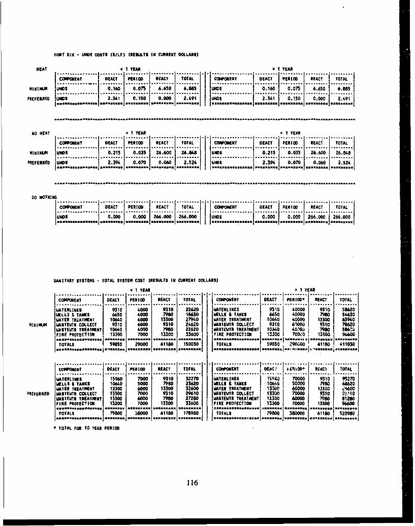
FORT DIXN UNDS COSTS (S/LF) IRESULTS IN CURRENT DOLLARS)
HEAT 'c I YEAR I YEAR
CGOMENT DEACT PERIOD REACT TOTAL COMPONENT DEACT PERIMD REACT ITOTAL......... ... ...... ... --
MINI MUM I)S 0.160 0.075 6.650 6.885 UNDS 0.160 0.075 6.650 6.885
PREFERRED UNDS ---------2.341' 0-.150' -0.000 2o491 AIDS 2.341 0.150 0.000 2.491*,SSUSUU*USUCSS *SSUS*S*U *U**U**** u*R sU ... S~ axesSflUS um%28nm us numu~ng samuassuu sas.S... *ss..j
No HEAT -cI YEAR j-1 YEAR
COMPONENT DEACT PERIOD REACT TOTAL COMPONENT DEACT PERIOD REACT TOTAL
pgIgINj WIMS 0.213 0.035 26.600 26.1148 UNDS 0.213l 0.035 26.600 26.848
PREFERRED UNOS 2.391 0.070 0.060 2.524 UNDS 2.394 0.070 0.060 Am2.524j.. ~f~a~fSUinamassaflU mennsUsUSfflSS ... m.62.9 SSUUWUUUSSUSS *CSaugus= 0USUS ... fM~ Masn ss .... suU
00 NOTHING
~WN T DCT PRO REACT TOTAL COMPOMNT DEACT PER IOD ' REACT: . TOTAL..
NMOS 0.000 0.000 266.000 266.000 UNDS 0.000 0 .000 266.000 266.000
SANITARY SYSTEMS TOTAL SYSTEM COST [RESULTS IN CURRENT DOLLARSS
,(1 YEAR 1 YEARI...............................I...............................---------------- ---- I ............... I......1COMPONENT DUACT PERIOD REACT TOTAL COMPONENT DUACT I PERIM* REACT TOTAL
WATERLINE$ 9310 4000 9310 22620 WATERLINES 9310 40000 9310 58620WEL I TANKS 6650 4000 7980 1863 WELLS & TANKS 6650 40000 798 54630WATER TREATMENT 10640 4000 13300 27940 WATER TREATMENT 10640 4G000 130I34
MIMI"J UASTEWTR COL.LECT 9310 6000 9310 24620 WASTEWTR COLLECT 9310 6100 9310 78620UASTEWTR TREATMENT 10640 4000 7980 22620 WASTEWTR TREATMENT 1 0640 "-IOU0 7980 S867.4
IF l * R E P R OT EC T I O N . 1 1 3 3 0 0 7 0 0 0 1 3 3 0 0 3 3 6 0 0 F I R E M S T E C T I O N 13 3 0 5C. 01 0 0 1 . 9 6 6 0
"TTASS95 29000 61180 150030 TOTALS "SO5 '9NOiO 61180 411030
.. U33uSUS~. 935fl*sss .s.... .... ..... 3SslU~~saSS.~S~]WA3Swjb,..SS lS4S
COPOEN EACT PERIOD REACT TOTAL COMPNENT OEC IW) EC TOTAL~~~..................... ........ ......... ......... .. I ...... ......................... ......... ......
WATERLINES 15960 70010 9310 32270 WATERLINES i5VE" 70000 9310 95270WELLS & TANKS 10640 5000 798 23620 WELLS & TANKS 10(64 50000 7980 68620WATER TREATMENT 13300 6000 13300 32600 WATER TREATMENT IM~0 60000 13300 C%600
PREFERRED WASTEWTR COLLECT 13300 7000 9310 29610 WASTEWTR COLLECT 13300 70000 9310 72140WASTEIJYR TREATMENT 13300 6000 7980 27280 UASTEWTR TREAINENT MO30 60000 798 81230FIRE PROTECTION 13300 7000 13300 33600 FIRE PROTECTION 13300 70000 13300 96600
TOAL19800- ... 8O000 61180 1788 TOTLS 79800 j OD 38"so 18 508
STOTAL FOR 10 YEAR PERIOD
116

FORT DIX - UNDERGRUO.ND STORAGE TANK COSTS ($/STANDARD TANK) (RESULTS IN CURRENT DOLLARS]"41 YEAR 4 45 DAYS 3,1 YEAR -c 45 DAYS
............................. ......... ......... ......... ............... ......... ..............COMPONENT DEACT PERIOD REACT TOTAL COPNT DEACT PERIOD REC TOA
TEMPORARY UST 41.90 200 4490 9180 UST N/A N/A M/A N/At------------.-.-------.-.-------.-.-------.-.------- ..... 0................... .......... . ....... ..I....
PERM IN PLAC UiST 19510 400 13500 33410 UST 19510 400 13500 I 33410
DISPOSE/REPL UST N/A N/A N/A N/A UST 149800 100I 290STORE/REINST UST N/A N/A N/A N/A UST 19510 200 8020 27730
4 1 YEAR > 45 DAYS ý, 1 YEAR >45 DAYS
COMPONENT DEACT PERIOD REACT TOTAL COMPONENT --- -DEACT PERIOD - 'REACT- _TOTAL:
TEMPORARY ------T-- 4490 .... 200. 44.90 .. 9`180. . UST ....... N/A .... N/A N/ ..MA .... N/A--------....--....---..o.. -............................. ......... ......... ....................-
PERM IN PLAC UST 195101 400 13500 33-410 UST 19510 400 13500 j 33410
(JISPOSE/REPL US 14980 0 1301 27990 UST 14980 0 13010 27990
STORE/REINST? .. US .... 195-10. 200 8020 2773 UST 19510 200. 8020 --- 7730.....mos.s~~ ss uma.l..us .... ...... 0.1 .... ....... .. ..... ** znsa
FORT DIX -ELECTRICAL DIST. SYSTEM COSTS (SFOR WHOLE SYSTEM) (RESULTS IN CURRENT DOLLARS)
4 1 YEAR ), 1 YEAR
COMPONENT DEACT PERIOD REACT TOTAL CMOET IDAT IPRO EC OAI DEC PEI O RECIOA
MINIMUM ELECT."SYSTEM- 3000 1000 8000 12000 ELECT. SYSTEM 3000 -3000 -- 20000- _ 26000
IL I....I......!0.0.100.400PREERRD EECT SYTEM 500 100 400 10000 ELECT. SYSTEM 1 7000 I 1000 1000 90
117

APPENDIX K:
EQUIVALENT UNIFORM ANNUAL COST (EUAC) SUMMARIES
DATE:= NOV/26/1990 PROJECTED COST ANALYSIS (DETAIL)
SECTION ID:=R-PINALTERNATIVE:= LT1_LT45_MIN HEATLIFE OF ALTERNATIVE:= 1 INTEREST RATE:= 10.0 INFLATION RATE:= 4.5
M&R ACTIVITY YEAR COST(S) PRESENT VALUE(S)DEACTIVATION 1990 .50 .50
PERIODIC M&R 1991 .00 .00HEAT 1991 1.26 1.20REACTIVATION 1991 .61 .58
ANNUAL TOTAL:= 1.87 1.78
INITIAL COST(S):= .50PRESENT VALUE(S):= 2.28EQUIVALENT UNIFORM ANNUAL COST(S).:= 2.50EUAC PER SQ. FT. ($):- 2.50
118

DATE:= NOV/26/1990 PROJECTED COST ANALYSIS (DETAIL)
SECTION ID:=R-PINALTERNATIVE:= GT1 LT45 MIN HEATLIFE OF ALTERNATIVE:= 11 INTEREST RATE:- 10.0 INFLATION RATE:- 4.5
M&R ACTIVITY YEAR COST(S) PRESENT VALUE($)
DEACTIVATION 1990 .46 .46
PERIODIC M&R 1991 .10 .09
HEAT 1991 1.26 1,20ANNUAL TOTAL:= 1.36 1.29
PERIODIC M&R 1992 .10 .09HEAT 1992 1.26 1.14
ANNUAL TOTAL:= 1.36 1.23
PERIODIC M&R 1993 .10 .08HEAT 1993 1.26 1.08
ANNUAL TOTAL:= 1.36 1.16
PERIODIC M&R 1994 .10 .08HEAT 1994 1.26 1.03
ANNUAL TOTAL:= 1.36 1.11
PERIODIC M&R 1995 .10 .08HEAT 1995 1.26 .97
ANNUAL TOTAL:- 1.36 1.05
PERIODIC M&R 1996 .10 .07HEAT 1996 1.26 .93
ANNUAL TOTAL:- 1.36 1.00
PERIODIC M&R 1997 .10 .07HEAT 1997 1.26 .88
ANNUAL TOTAL:- 1.36 .95
PERIODIC M&R 1998 .10 .07HEAT 1998 1.26 .84
ANNUAL TOTAL:= 1.36 .90
PERIODIC M&R 1999 .10 .06HEAT 1999 1.26 .79
ANNUAL TOTAL:- 1.36 .86
PERIODIC M&R 2000 .10 .06HEAT 2000 1.26 .75REACTIVATION 2000 2,31 1.38
ANNUAL TOTAL:- 3.66 2.19
INITIAL COST(S):- .46.PRESENT VALUE(S):- 12.20EQUIVALENT UNIFORM ANNUAL COST($):= 1.88EUAC PER SQ. FT. ($):= 1.88
119

DATE:- NOV/26/1990 PROJECTED COST ANALYSZS (DETAIL)
SECTION ID:-R-PINALTERNATIVE:- LTI LT45 PRF HEATLIFE OF ALTERNATIVE:- -1 IRTEREST RATE:- 10.0 7NFLATION RATE:- 4.5
K&R ACTiIVITY YEAR COST(S) PRESENT VALUE($)DEACTIVATION 1990 .74 .74
PERIODIC M&R 1991 .13 .12HEAT 1991 1.26 1.20REACTIVATION 1991 .23 .22
ANNUAL TOTAL:- 1.62 1.54
INITIAL COST($):- .74PRESENT VALUE($):- 2.28EQUIVALENT UNIFORM ANNUAL COST($):- 2.51EUAC PER SQ. FT. ($):- 12.51
120

DATE:= NOV/26/1990 PROJECTED COST ANALYSIS (DETAIL)
SECTION ID:=R-PINALTERNATIVE:- GTI LT45 PRF HEATLIFE OF ALTERNATIVE:- 11 INTEREST RATE:- 10.0 INFLATION RATE:- 4.5
M&R ACTIVITY YEAR COST(S) PRESENT VALUE($)DEACTIVATION 1990 .58 .58
PERIODIC M&R 1991 .13 .12HEAT 1991 1.26 1.20
ANNUAL TOTAL:- 1.39 1.32
PERIODIC M&R 1992 .13 .12HEAT 1992 1.26 1.14
ANNUAL TOTAL:- 1.39 1.25
PERIODIC M&R 1993 .13 .11HEAT 1993 1.26 1.08
ANNUAL TOTAL:= 1.39 1.19
PERIODIC M&R 1994 .13 .11HEAT 1994 1.26 1.03
ANNUAL TOTAL:= 1.39 1.13
PERIODIC M&R 1995 .13 .10HEAT 1995 1.26 .97
ANNUAL TOTAL:- 1.39 1.08
PERIODIC M&R 1996 .13 .10HEAT 1996 1.26 .93
ANNUAL TOTAL:- 1.39 1.02
PERIODIC M&R 1997 .13 .09HEAT 1997 1.26 .88
ANNUAL TOTAL:- 1.39 .97
PERIODIC M&R 1998 .13 .09HEAT 1998 1.26 .84
ANNUAL TOTAL:- 1.39 .92
PERIODIC M&R 1999 .13 .08HEAT 1999 1.26 .79
ANNUAL TOTAL:- 1.39 .88
PERIODIC M&R 2000 .13 .08HEAT 2000 1.26 .75REACTIVATION 2000 1.52 .91
ANNUAL TOTAL:- 2.91 1.74
INITIAL COST($):- .58PRESENT VALUE($):- 12.09EQUIVALENT UNIFORM ANNUAL COST($)--= 1.86EUAC PER SQ. FT. ($):- 1.86
121

DATE:= NOV/26/1990 PROJECTED COST ANALYSIS (DETAIL)
SECTION ID:=R-PINALTERNATIVE:= LT1 LT45 MIN NOHEATLIFE OF AT,,TERNATIVE: -1 INTEREST RATE:- 10.0 INFLATION RATE:- 4.5
M&R ACTIVITY YEAR COST(S) PRESENT VALUE($)DEACTIVATION 1990 .47 A7
PERIODIC M&R 1991 .00 .00REACTIVATION 1991 .70 .66
ANNUAL TOTAL:= .70 .66
INITIAL COST($):= .47PRESENT VALUE(S):= 1.13EQUIVALENT UNIFORM ANNUAL COST(S):= 1.25EUAC PER SQ. FT. ($):= 1.25
DATE:= DEC/04/1990 PROJECTED COST ANALYSIS (DETAIL)
SECTION ID:=R-PINALTERNATIVE:- GT1 LT45_KIN NOHEATLIFE OF ALTERNATIVE:- 11 INTEREST RATE:- 10.0 INFLATION RATE:- 4.5
M&R ACTIVITY YEAR COST(S) PRESENT VALUE($)DEACTIVATION 1990 .44 .44PERIODIC M&R 1991 .07 .07PERIODIC M&R 1992 .07 .06PERIODIC M&R 19S3 .07 .06PERIODIC M&R 1.994 .07 .06PERIODIC H&R 1995 .07 ý05PERIODIC M&R 1996 .07 .05PERIODIC M&R 1997 .07 .05PERIODIC M&R 1998 .07 .05PERIODIC M&R 1999 .07 .04
PERIODIC M&R 2000 .07 .04REACTIVATION 2000 3.10 1,85
ANNUAL TOTAL:= 3.16 1.89
INITIAL COST($) :- .44PRESENT VALUE(S):- 2.81EQUIVALENT UNIFORM ANNUAL COST(S);= .43EUAC PER SQ. FT. ($):- .43
122

DATE:- DEC/04/1990 PROJECTED COST ANALYSIS (DETAIL)
SECTION ID:-R-PINALTERNATIVE:= LT1_LT45_PRF NOHEATLIFE OF ALTERNATIVE:- 1 INTEREST RATE:- 10.0 INFLATION RATE:- 4.5
M&R ACTIVITY YEAR COST(S) PRESENT VALUE($)DEACTIVATION 1990 .77 .77
PERIODIC M&R 1991 .10 .10REACTIVATION 1991 .28 .27
ANNUAL TOTAL:= .38 .36
INITIAL COST(S):- .77PRESENT VALUE(S):- 1.13EQUIVALENT UNIFORM ANNUAL COST(S):- 1.25EUAC PER SQ. FT. ($):- 1.25
DATE:= DEC/04/1990 PROJECTED COST ANALYSIS (DETAIL)
SECTION ID:=R-PINALTERNATIVE:- GT1_LT45_PRF NOHEATLIFE OF ALTERNATIVE:- 11 INTEREST RATE:- 10.0 INFLATION RATE:- 4.5
M&R ACTIVITY YEAR COST(S) PRESENT VALUE(S)DEACTIVATION 1990 .61 .61PERIODIC M&R 1991 .10 .10PERIODIC M&R 1992 .10 .09PERIODIC M&R 1993 .10 .09PERIODIC M&R 1994 .10 .08PERIODIC M&R 1995 .10 .08PERIODIC M&R 1996 .10 .08PERIODIC M&R 1997 .10 .07PERIODIC M&R 1998 .10 .07PERIODIC M&R 1999 .10 .07
PERIODIC M&R 2000 .10 .06REACTIVATION 2000 2.02 1.21
ANNUAL TOTAL:- 2.13 1.27
INITIAL COST($):- .61PRESENT VALUE($):%. 2.61EQUIVALENT UNIFORM ANNUAL COST(S):- .40EUAC PER SQ, FT. ($):- .40
123

DATE:= NOV/26/1990 PROJECTED COST ANALYSIS (DETAIL)
SECTTON ID:=R-PINALTERNATIVE:= LTI GT45_MINNOHEATLIFE OF ALTERNA7IVE:- 1 TNTEREST RATE:- 10.0 INFLATION RATE:= 4.5
M&R ACTIVITY YEAR COST(S) PRESENT VALUE(S)DEACTIVATION 1990 .47 .47
PERIODIC M&R 1991 .00 .00REACTIVATION 1991 .70 .66
ANNUAL TOTAL:- .70 .66
INITIAL COST($):= .47PRESENT VALUE($):= 1.13EQUIVALENT UNIFORM ANNUAL COST(S):= 1.25EUAC PER SQ. FT. ($):- 1.25
DATE:- NOV/26/1990 PROJECTED COST ANALYSIS (DETAIL)
SECTION ID:-R-PINALTERNATIVE:- LTIGT45_MIN NOHEATLIFE OF ALTERNATIVE:- I INTEREST RATE:- 10.0 INFLATION RATE:- 4.5
M&R ACTIVITY YEAR COST(S) PRESENT VALUE(S)DEACTIVATION 1990 .47 .47
PERIODIC M&R 1991 .00 .00REACTIVATION 1991 .83 .79
ANNUAL TOTAL;- .83 .79
INITIAL COST(S):- .47PRESENT VALUE(S):- 1.27EQUIVALENT UNIFORM MNNUAL COST(S):= 1.39EUAC PER SQ. FT. ($):- 1.39
124

DATE:- NOV/26/1990 PROJECTED COST ANALYSIS (DETAIL)
SECTION ID:-R-PINALTERNATIVE:- GT1 GT45_KIN NOHEATLIFE OF ALTERNATIVE:- 11 INTEREST RATE:- 10.0 INFLATION RATE:- 4.5
M&R ACTIVITY YEAR COST(S) PRESENT VALUE($JDEACTIVATION 1990 .44 .44PERIODIC M&R 1991 .06 .05PERIODIC M&R 1992 .06 .05PERIODIC M&R 1993 .06 .05PERIODIC MAR 1994 .06 .05PERIODIC M&R 1995 .06 .04PERIODIC M&R 1996 .06 .04PERIODIC MAR 1997 .06 .04PERIODIC M&R 1998 .06 .04PERIODIC M&R 1999 .06 .04
PERIODIC M&R 2000 .06 .03REACTIVATION 2000 3.43 2.05
ANNUAL TOTAL-.- 3.48 2.09
INITIAL COST(S):- .44PRESENT VALUE(S):- 2.91EQUIVALENT UNIFORM ANNUAL COST(S):- .45EUAC PER SQ. FT. ($):- .45
DA.TZ:- NOV/26/1990 PROJECTED COST ANALYSIS (DETAIL)
SECTION ID:-R-PINALTERNATIVE: - LTI GT45_PIKF NOHEATLIFE OF ALTERNATIVE:- I INTEREST RATE:- 10.0 INFLATION RATE:- 4.5
M&R ACTIVITY YEAR COST(S) PRESENT VALUE($)DEACTIVATION 1990 .77 .77
PERIODIC M&R 1991 .3]0 .10REACTIVATION 1991 .28 .27
ANNUAL TOTAL:- .38 .36
INITIAL COST(S):- .77PRESENT VALUE($):- 1.13EQUIVALENT UNIFORM ANNUAL COST(S):- 1.25EUAC PER SQ. FT. ($):- 1.25
125

DATE:= NOV/26/1990 PROJECTED COST ANALYSIS (DETAIL)
SECTION ID:-R-PINALTERNATIVE:- GT1 GT45 PRF NOREATLIFE OF ALTERNATIVE:- 11 IRTEREST RATE:- 10.0 INFLATION RATE:- 4.5
MAR ACTIVITY YEAR COST(S) PRESENT VALUE($)
DEACTIVATION 1990 .61 .61
PERIODIC MAR 1991 .08 .08
PERIODIC MAR 1992 .08 .07
PERIODIC MAR 1993 .08 .07
PERIODIC MAR 1994 .08 .07
PERIODIC MAR 1995 .08 .06
PERIODIC MAR 1996 .08 .06
PERIODIC MAR 1997 .08 .06
PERIODIC MAR 1998 .08 .06
PERIODIC MAR 1999 .08 .05
PERIODIC MAR 2000 .08 .05
REACTIVATION 2000 2.24 1.34ANNUAL TOTAL:- 2.33 1.39
INITIAL COST($):- .61PRESENT VALUE($):- 2.59EQUIVALENT UNIFORM ANNUAL COST($):- .40EUAC PER SQ. FT. .40
DATE:- NOV/26/1990 PROJECTED COST ANALYSIS (DETAIL)
SECTION ID:-R-PINALTERNATIVE:- LT1_D0 NOTHINGLIFE OF ALTERNATIVE:- 1 INTEREST RATE:- 10.0 INFLATION RATE:- 4.5
MAR ACTIVITY YEAR COST(S) PRESENT VALUE($)DEACTIVATION 1990 .00 .00
PERIODIC MAR 1991 .00 .00REACTIVATION 1991 33.34 31.67
ANNUAL TOTAL:- 33.34 31.67
INITIAL COST($):- .00PRESENT VALUE($):- 31.67EQUIVALENT UNIFORM ANNUAL COST($):- 34.84EUAC PER SQ. FT. ($):- 34.84
126

DATE:- NOV/26/1990 PROJECTED COST ANALYSIS (DETAIL)
SECTION ID:-R-PINALTERNATIVE:- GT1_.DO NOTHINGLIFE OF ALTERNATIVE:- 11 INTEREST RATE:- 10.0 INFLATION RATE:- 4.5
M&R ACTIVITY YEAR COST(S) PRESENT VALUE($)DEACTIVATION 1990 .00 .00PERIODIC M&R 1991 .00 .00PERIODXC M&R 1992 .00 .00PERIODIC M&R 1993 .00 .00PERIODIC M&R 1994 .00 .00PERIODIC M&R 1995 .00 .00PERIODIC M&R 1996 .00 .00PERIODIC M&R 1997 .00 .00PERIODIC M&R 1998 .00 .00PERIODIC M&R 1999 .00 .00
PERIODIC M&R 2000 .00 .00REACTIVATION 2000 40.11 24.02
ANNUAL TOTAL:- 40.11 24.02
INITIAL COST(S):- .00PRESENT VALUE(S):- 24.02EQUIVALENT UNIFORM ANNUAL COST(S):- 3.70EUAC PER SQ. FT. ($):- 3.70
DATE:- NOV/26/1990 PROJECTED COST ANALYSIS (DETAIL)
SECTION ID:-UHDSALTERNATIVE:- LT1_MINHEATLIFE OF ALTERNATIVE:- I INTEREST RATE:- 10.0 INFLATION RATE:- 4.5
M&R ACTIVITY YEAR COST(S) PRESENT VALUE($)DEACTIVATION 1990 .16 .16
PERIODIC M&R 1991 .08 .07REACTIVATION 1991 6.65 6.32
ANNUAL TOTAL:- 6.72 6.39
INITIAL COST(S):- .16PRESENT VALUE(S):= 6.55EQUIVALENT UNIFORM ANNUAL COST($):-m 7.20EUAC PER L.F. ($):- 7.20
127

DATE:- NOV/26/1990 PROJECTED COST ANALYSIS (DETAIL)
SECTION ID:-UHDSALTERNATIVE:- GTI MIN HEATLIFE OF ALTERNATIVE:- 11 INTEREST RATE:- 10.0 INFLATION RATE:- 4.5
M&R ACTIVITY YEAR COST(S) PRESENT VALUE($)DEACTIVATION 1990 .16 .16PERIODIC M&R 1991 .08 .07PERIODIC M&R 1992 .08 .07PERIODIC M&R 1993 .08 .06PERIODIC M&R 1994 .08 .06PERIODIC M&R 1995 .08 .06PERIODIC M&R 1996 .08 .06PERIODIC M&R 1997 .08 .05PERIODIC M&R 1998 .08 .05PERIODIC M&R 1999 .08 .05
PERIODIC M&R 2000 .08 .04REACTIVATION 2000 6.65 3.98
ANNUAL TOTAL:- 6.72 4.03
INITIAL COST(S):- .16PRESENT VALUE(S):- 4.71EQUIVALENT UNIFORM ANNUAL COST(S):- .73EUAC PER L.F. ($):- .73
DATE:- NOV/26/1990 PROJECTED COST ANALYSIS (DETAIL)
SECTION ID:-UHDS
ALTERNATIVE:- LTIPRF HEATLIFE OF ALTERNATIVE:- 1 INTEREST RATE:- 10.0 INFLATION RATE:- 4.5
M&R ACTIVITY YEAR COST(S) PRESENT VALUE($)DEACTIVATION 1990 2.34 2.34
PERIODIC M&R 1991 .15 .14REACTIVATION 1991 .00 .00
ANNUAL TOTAL:- .15 .14
INITIAL COST(S):- 2.34PRESENT VALUE($):- 2.48EQUIVALENT UNIFORM ANNUAL COST(S):- 2.73EUAC PER L.F. ($):= 2.73
128

DATE:- NOV/26/1990 PROJECTED COST ANALYSIS (DETAIL)
SECTION ID:-UHDSALTERNATIVE:- GT1 PRF HEATLIFE OF ALTERNATIVE:--II1 INTEREST RATE:- 10.0 INFLATION RATE:- 4.5
M&R ACTIVITY YEAR COST(S) PRESENT VALUE(S)
DEACTIVATION 1990 2.34 2.34
PERIODIC M&R 1991 .15 .14
PERIODIC M&R 1992 .15 .14
PERIOrr-= M&R 1993 .15 .13
PERIODIC M&R 1994 .15 .12
PERIODIC M&R 1995 .15 .12
PERIODIC M&R 1996 .15 .11
PERIODIC M&R 1997 .15 .10
PERIODIC M&R 1998 .15 .10
PERIODIC M&R 1999 .15 .09
PERIODIC M&R 2000 .15 .09
REACTIVATION 2000 .00 .00
ANNUAL TOTAL:- .15 .09
INITIAL COST(S) :- 2.34
PRESENT VALUE(S):- 3.48
EQUIVALENT UNIFORM ANNUAL COST(S) :- .54
EUAC PER L.F. (S):- .54
DATE:- NOV/26/1990 PROJECTED COST ANALYSIS (DETAIL)
SECTION ID:-UHDSALTERNATIVE:- LT1_MINNOHEATLIFE OF ALTERNATIVE:- 1 INTEREST RATE;- 10.0 INFLATION RATE:- 4.5
M&R ACTIVITY YEAR COST(S) PRESENT VALUE($)
DEACTIVATION 1990 .21 .21
PERIODIC M&R 1991 .04 .03
REACTIVATION 1991 26.60 25.27ANNUAL TOTAL:- 26.64 25.30
INITIAL COST(S):- .21PRESENT VALUE(S):- 25.52EQUIVALENT UNIFORM ANNUAL COST(S):- 28.07EUAC PER L.F. ($):- 28.07
129

DATE:- NOV/26/1990 PROJECTED COST ANALYSIS (DETAIL)
SECTION ID:-UHDSALTERNATIVE:- GT1_MINNOHEATLIFE OF ALTERNATIVE:- 11 INTEREST RATE:- 10.0 INFLATION RATE:- 4.5
M&R ACTIVITY YEAR COST(S) PRESENT VALUE($)
DEACTIVATION 1990 .21 .21
PERIODIC M&R 1991 .04 .03
PERIODIC M&R 1992 .04 .03
PERIODIC M&R 1993 .04 .03
PERIODIC M&R 1994 .04 .03
PERIODIC M&R 1995 .04 .03
PERIODIC M&R 1996 .04 .03
PERIODIC M&R 1997 .04 .02
PERIODIC M&R 1998 .04 .02
PERIODIC M&R 1999 .04 .02
PERIODIC M&R 2000 .04 1,:02
REACTIVATION 2000 26.60 93
ANNUAL TOTAL:- 26.64 15.95
INITIAL COST($):: .21PRESENT VALUE($):- 16.41
EQUIVAT.ENT UNIFORM ANNUAL COST($):- 2.53EUAC PER L.F. ($):- 2.53
DATE:- NOV/26/1990 PROJECTED COST ANALYSIS (DETAIL)
SECTION ID:-UHDSALTERNATIVE:- LTi-PRF-NOHEATLIFE OF ALTERNATIVE:- 1 INTEREST RATE:- 10.0 INFLATION RATE:- 4.5
M&R ACTIVITY YEAR COST(S) PRESENT VALUE($)DEACTIVATION 1990 2.39 2.39
PERIODIC M&R 1991 .07 .07REACTIVATION 1991 .06 .06
ANNUAL TOTAL:- .13 .12
INITIAL COST($):- 2.39PRESENT VALUE($):- 2.52EQUIVALENT UNIFORM ANNUAL COST($):- 2.77EUAC PER L.F. ($):- 2.77
130

DATE:- NOV/26/1990 PROJECTED COST ANALYSIS (DETAIL)
SECTION ID:-UHDSALTERNATIVE:- GT1_PRFNOHEATLIFE OF ALTERNATIVE:- 11 INTEREST RATE:- 10.0 INFLATION RATE:- 4.5
M&R ACTIVITY YEAR COST(S) PRESENT VALUE($)DEACTIVATION 1990 2.39 2.39PERIODIC M&R 1991 .07 .07PERIODIC M&R 1992 .07 .06PERIODIC M&R 1993 .07 .06PERIODIC M&R 1994 .07 .06PERIODIC M&R 1995 .07 .05PERIODIC M&R 1996 .07 .05PERIODIC M&R 1997 .07 .05PERIODIC M&R 1998 .07 .05PERIODIC M&R 1999 .07 .04
PERIODIC M&R 2000 .07 .04REACTIVATION 2000 .06 .04
ANNUAL TOTAL:- .13 .08
INITIAL COST(S):- 2.39PRESENT VALUE(S):- 2.96EQUIVALENT UNIFORM ANNUAL COST(S):- .46EUAC PER L.F. ($):- .46
DATE:- NOV/26/1990 PROJECTED COST ANALYSIS (DETAIL)
SECTION ID:-UHDSALTERNATIVE:- LTI.DO NOTHINGLIFE OF ALTERNATIVE:- 1 INTEREST RATE:- 10.0 INFLATION RATE:- 4.5
M&R ACTIVITY YEAR COST(S) PRESENT VALUE($)DEACTIVATION 1990 .00 .00
PERIODIC H&R 1991 .00 .00REACTIVATION 1991 266.00 252.70
ANNUAL TOTAL:- 266.00 252.70
INITIAL COST(S):- .00PRESENT VALUE(S):- 252.70EQUIVALENT UNIFORM ANNUAL COST($):- 277.97EUAC PER L.F. ($):- 277.97
131

DATE:= NOV/26/1990 PROJECTED COST ANALYSIS (DETAIL)
SECTION ID:-UHDSALTERNATIVE:- GT1 DO NOTHINGLIFE OF ALTERNATIVE:- 11 INTEREST RATE:- 10.0 INFLATION RATE:- 4.5
M&R ACTIVITY YEAR COST(S) PRESENT VALUE(S)DEACTIVATION 1990 .00 .00PERIODIC M&R 1991 .00 .00PERIODIC M&R 1992 .00 .00PERT..ýIC M&R 1993 .00 .00PERIODIC M&R 1994 .00 .00PERIODIC M&R 1995 .00 .00PERIODIC M&R 1996 .00 .00PERIODIC M&R 1997 .00 .00PERIODIC M&R 1998 .00 .00PERIODIC M&R 1999 .00 .00
PERIODIC M&R 2000 .00 .00REACTIVATION 2000 266.00 159.26
ANNUAL TOTAL:- 266.00 159.26
INITIAL COST(S):= .00PRESENT VALUE(S):- 159.26EQUIVALENT UNIFORM ANNUAL COST(S):- 24.52EUAC PER L.F. ($):- 24.52
DATE:- NOV/26/1990 PROJECTED COST ANALYSIS (DETAIL)
SECTION ID:-USTALTERNATIVE:- LT1 TEMPLIFE OF ALTERNATIVE:m 1 INTEREST RATE:= 10.0 INFLATION RATE:- 4.5
M&R ACTIVITY YEAR COST(S) PRESENT VALUE(S)DEACTIVATION 1990 4490.00 4490.00
PERIODIC M&R 1991 200.00 190.00REACTIVATION 1991 4490.00 4265.50
ANNUAL TOTAL:- 4690.00 4455.50
INITIAL COST(S):- 4490.00PRESENT VALUE(S):- 8945.50EQUIVALENT UNIFORM ANNUAL COST($):= 9840.05EUAC PER TANK (5):- 9840.05
132

DATE:- NOV/27/1990 PROJECTED COST ANALYSIS (DETAIL)
SECTION ID:-USTALTERNATIVE:- LT1_PERM IN PLACELIFE OF ALTERNATIVE:- 1 INTEREST RATE:- 10.0 INFLATION RATE:- 4.5
M&R ACTIVITY YEAR COST(S) PRESENT VALUE(S)DEACTIVATION 1990 19510.00 19510.00
PERIODIC M&R 1991 400.00 380.00REACTIVATION 1991 13500.00 12825.00
ANNUAL TOTAL:- 13900.00 13205.00
INITIAL COST(S):- 19510.00PRESENT VALUE(S):- 32715.00EQUIVALENT UNIFORM ANNUAL COST(S):- 35986.49EUAC PER TANK ($):- 35986.49
DATE:- NOV/27/1990 PROJECTED COST ANALYSIS (DETAIL)
SECTION ID:-USTALTERNATIVE:- GT1 PERM IN PLACELIFE OF ALTERNATIVE:- 11 INTEREST RATE:= 10.0 INFLATION RATE:- 4.5
M&R ACTIVITY YEAR COST(S) PRESENT VALUE(S)DEACTIVATION 1990 19510.00 19510.00PERIODIC MAR 1991 400.00 380.00PERIODIC M&R 1992 400.00 361.00PERIODIC M&R 1993 400.00 342.95PERIODIC M&R 1994 400.00 325.80PERIODIC M&R 1995 400.00 309.51PERIODIC M&R 1996 400.00 294.04PERIODIC M&R 1997 400.00 279.33PERIODIC M&R 1998 400.00 265.37PERIODIC M&R 1999 400.00 252.10
PERIODIC M&R 2000 400.00 239.49REACTIVATION 2000 13500.00 8082.94
ANNUAL TOTAL:- 13900.00 8322.44
INITIAL COST($):- 19510.00PRESENT VALUE(S):- 30642.54EQUIVALENT UNIFORM ANNUAL COST(S):- 4717.82EUAC PER TANK ($):- 4717.82
133

DATE:= NOV/27/1990 PROJECTED COST ANALYSIS (DETAIL)
SECTION ID:-USTALTERNATIVE:- LT1..DISPOSE/REPLACELIFE OF ALTERNATIVE:- 1 INTEREST RATE:- 10.0 INFLATION RATE:- 4.5
M&R ACTIVITY YEAR COST(S) PRESENT VALUE($)DEACTIVATION 1990 14980.00 14980.00
PERIODIC M&R 1991 .00 .00REACTIVATION 1991 13010.00 12359.50
ANNUAL TOTAL:= 13010.00 12359.50
INITIAL COST(S):- 14980.00PRESENT VALUE(S)-= 27339.50EQUIVALENT UNIFORM ANNUAL COST($):= 30073.44EUAC PER TANK ($):= 30073.44
DATE:- NOV/26/1990 PROJECTED COST ANALYSIS (DETAIL)
SECTION ID:-USTALTERNATIVE:- GT1_DISPOSE/REPLACELIFE OF ALTERNATIVE:- 11 INTEREST RATE:- 10.0 INFLATION RATE:- 4.5
M&R ACTIVITY YEAR COST(S) PRESENT VALUE($)DEACTIVATION 1990 14980.00 14980.00PERIODIC M&R 1991 .00 .00PERIODIC M&R 1992 .00 .00PERIODIC M&R 1993 .00 .00PERIODIC M&R 1994 .00 .00PERIODIC M&R 1995 .00 .00PERIODIC M&R 1996 .00 .00PERIODIC M&R 1997 .00 .00PERIODIC M&R 1998 .00 .00PERIODIC M&R 1999 .00 .00
PERIODIC M&R 2000 .00 .00REACTIVATION 2000 13010.00 7789.56
ANNUAL TOTAL:- 13010.00 7789.56
INITIAL COST(S):- 14980.00PRESENT VALUE($):- 22769.56EQUIVALENT UNIFORM ANNUAL COST(S):- 3505.67EUAC PER TANK ($):- 3505.67
134

DATE:- NOV/27/1990 PROJECTED COST ANALYSIS (DETAIL)
SECTION 1D:-USTALTERNATIVE:- LT1_STORE/REINSTALLLIFE OF ALTERNATIVE:- I INTEREST RATE:- 10.0 INFLATION RATE:- 4.5
M&R ACTIVITY YEAR COST(S) PRESENT VALUE(S)DEACTIVATION 1990 19510.00 19510.00
PERIODIC M&R 1991 200.00 190.00REACTIVATION 1991 8020.00 7619.00
ANNUAL TOTAL:- 8220.00 7809.00
INITIAL COST(S):- 19510.00PRESENT VALUE($):- 27319.00EQUIVALENT UNIFORM ANNUAL COST(S):= 30050.89EUAC PER TANK ($):- 30050.89
DATE:- NOV/26/1990 PROJECTED COST ANALYSIS (DETAIL)
SECTION ID:-USTALTERNATIVE:- GT1 STORE/REINSTALLLIFE OF ALTERNATIVE:- 11 INTEREST RATE:- 10.0 INFLATION RATE:- 4.5
M&R ACTIVITY YEAR COST(S) PRESENT VALUE(S)DEACTIVATION 1990 19510.00 19510.00PERIODIC M&R 1991 200.00 190.00PERIODIC M&R 1992 200.00 180.50PERIODIC M&R 1993 200.00 171.47PERIODIC M&R 1994 200.00 162.90PERIODIC M&R 1995 200.00 154.76PERIODIC M&R 1996 200.00 147.02PERIODIC M&R 1997 200.00 139.67PERIODIC M&R 1998 200.00 132.68PERIODIC M&R 1999 200.00 126.05
PERIODIC M&R 2000 200.00 119.75REACTIVATION 2000 8020.00 4801.87
ANNUAL TOTAL:- 8220.00 4921.61
INITIAL COST($):- 19510.00PRESENT VALUE(S):- 25836.67EQUIVALENT UNIFORM ANNUAL COST(S):- 3977.89EUAC PER TANK ($):- 3977.89
135

DATE:- NOV/26/1990 PROJECTED COST ANALYSIS (DETAIL)
SECTION ID:-SANITARYALTERNATIVE:- LT1 MINLIFE OF ALTERNATIVE:- 1 INTEREST RATE:- 10.0 INFLATION RATE:- 4.5
M&R ACTIVITY YEAR COST(S) PRESENT VALUE(S)DEACTIVATION 1990 59850.00 59850.00
PERIODIC M&R 1991 29000.00 27550.00REACTIVATION 1991 61180.00 58121.00
ANNUAL TOTAL:- 90180.00 85670.99
INITIAL COST(S:- 59350.00PRESENT VALUE($):- 145521.00EQUIVALENT UNIFORM ANNUAL COST(S):- 160073.10EUAC FOR SYSTEM ($):- 160073.10
DATE:- NOV/26/1990 PROJECTED COST ANALYSIS (DETAIL)
SECTION ID:-SNITARYALTERNATIVE:- GT1IMINLIFE OF ALTERNATIVE:- 11 INTEREST RATE:- 10.0 INFLATION RATE:- 4.5
M&R ACTIVITY YEAR COST(S) PRESENT VALUE($)DEACTIVATION 1990 59850.00 59850.00PERIODIC M&R 1991 29000.00 27550.00PERIODIC M&R 1992 29000.00 26172.50PERIODIC M&R 1993 29000.00 24863.87PERIODIC M&R 1994 29000.00 23620.67PERIODIC M&R 1995 29000.00 22439.64PERIODIC M&R 1996 29000.00 21317.66PERIODIC M&R 1997 29000.00 20251.77PERIODIC M&R 3,998 29000.00 19239.18PERIODIC M&R 1999 29000.00 18277.22
PERIODIC M&R 2000 29000.00 17363.36REACTIVATION 2000 61180.00 36630.70
ANNUAL TOTAL:- 90180.00 53994.06
INITIAL COST(S):- 59850.00PRESENT VALUE(S):- 317576.60EQUIVALENT UNIFORM ANNUAL COST(S):- 48895.08EUAC FOR SYSTEM ($):- 48895.08
136

DATE:- NOV/26/1990 PROJECTED COST ANALYSIS (DETAIL)
SECTION ID:-SANITARYALTERNATIVE:- LT1_PRFLIFE OF ALTERNATIVE:- 1 INTEREST RATE:- 10.0 INFLATION RATE:- 4.5
M&R ACTIVITY YEAR COST(S) PRESENT VALUE(S)DEACTIVATION 1990 79800.00 79800.00
PERIODIC M&R 1991 38000.00 36100.00RFACTIVATXON 1991 61180.00 58121.00
AýNUAL TOTAL:- 99180.00 94220.99
INITIAL COST(%j:- 79800.00PRESENT VALUE($):- 174021.00EQUIV&LENT UIIFORM ANNUAL COST(S):" 191423.10EUAC FOR SVSTEM ($):- 191423.10
DATE:= NOV/2611990 FROJECTED COST ANALYSIS (DETAIL)
SECTION ID:-SANITARYALTERNATIVE:- GTI PRULIFE OF ALTERNATIVE:- 11 XNTEREST RATE:- 10.0 INFLATION RATE:- 4.5
M&R ACTIVITY YFAR COST(S) PRESENT VALUE(S)DEACTIVATION 1i90 79800.00 79800.00PERIODIC M&R 1991 38000.00 36100.00PERIODIC M&R 1992 38000.00 34295.00PERIODIC M&R 1993 38000.00 32580.24PERIODIC M&R 1994 38000.00 30951.23PERIODIC M&R 1995 38000.00 29403.67PERIODIC M&R 1996 38000.00 27933.48PERIODIC M&R 1997 38000.00 26536.81PERIODIC M&R 1998 38000.00 25209.96PERIODIC M&R 1999 38000.00 23949.46
PERIODIC M&R 2000 38000.00 22751.99REACTIVATION 2000 61180.00 36630.70
ANNUAL TOTAL:- 99180.00 59382.69
INITIAL COST(S):- 79800.00PRESENT VALUE($) :- 406142 . 60EQUIVALENT UNIFORM ANNUAL COST(S):- 62530.98EUAC FOR SYSTEM ($):- 62530.98
137

DATL:= NOV/27/1990 PROJECTED COST ANALYSIS (DETAIL)
SECTION ID:-ELECTRICAL DIST.ALTERNATIVE:- LT1 MINLIFE OF ALTERNATIVE:- 1 INTEREST RATE:- 10.0 INFLATION RATE:- 4.5
M&R ACTIVITY YEAR COST(S) PRESENT VALUE(S)DEACTIVATION 1990 3000.00 3000.00
PERIODIC M&R 1991 1000.00 950.00REACTIVATION 1991 8000.00 7600.00
ANNUAL TOTAL:- 9000.00 8550.00
INITIAL COST(S):= 3000.00PRESENT VALUE(S):- 11550.00EQUIVALENT UNIFORM ANNUAL COST(S):- 12705.00EUAC FOR SYSTEM ($):- 12705.00
DATE:= NOV/27/1990 PROJECTED COST ANALYSIS (DETAIL)
SECTION ID:-ELECTRICAL DIST.ALTERNATIVE:= GTI YINLIFE OF ALTERNATIVE:- 11 INTEREST RATE:- 10.0 INFLATION RATE:- 4.5
M&R ACTIVITY YEAR COST(S) PRESENT VALUE(S)DEACTIVATION 1990 3000.00 3000.00PERIODIC M&R 1991 3000.00 2850.00PERIODIC M&R 1992 3000.00 2707.50PERIODIC M&R 1993 3000.00 2572.12PERIODIC M&R 1994 3000.00 2443.52PERIODIC M&R 1995 3000.00 2321.34PERIODIC M&R 1996 3000.00 2205.27PERIODIC M&R 1997 3000.00 2095.01PERIODIC M&R 1998 3000.00 1990.26PERIODIC M&R 1999 3000.00 1890.75
PERIODIC M&R 2000 3000.00 1796.21REACTIVATION 2000 20000.00 11974.73
ANNUAL TOTAL:- 23000.00 13770.94
INITIAL COST(S):- 3000.00PRESFNT VALUE(S):- 37846.72EQUIVALENT UNIFORM ANNUAL COST(S):- 5827.00EUAC FOR SYSTEM ($):- 5827.00
138

DATE:- NOV/27/1990 PROJECTED COST ANALYSIS (DETAIL)
SECTION ID:FELECTRICAL DIST.ALTERNATIVE:- LT1" PRFLIFE OF ALTERNATIVE:- 1 INTEREST RATE:- 10.0 INFLATION RATE:- 4.5
M&R ACTIVITY YEAR COST(S) PRESENT VALUE($)DEACTIVATION 1990 5000.00 5000.00
PERIODIC M&R 1991 1000.00 950.00REACTIVATION 1991 4000.00 3800.00
ANNUAL TOTAL:- 5000.00 4750.00
INITIAL COST($):- 5000.00PRESENT VALUE(S):- 9750.00EQUIVALENT UNIFORM ANNUAL COST($):- 10725.00EUAC FOR SYSTEM (5):- 10725.00
DATE:- NOV/27/1990 PROJECTED COST ANALYSIS (DETAIL)
SECTION ID:-ELECTRICAL DIST.ALTERNATIVE:- GT1_PRFLIFE OF ALTERNATIVE:= 11 INTEREST RATE:- 10.0 INFLATION RATE:- 4.5
M&R ACTIVITY YEAR COST(S) PRESENT VALUE($)DEACTIVATION 1990 7000.00 7000.00PERIODIC M&R 1991 1000.00 950.00PERIODIC M&R 1992 1000.00 902.50PERIODIC M&R 1993 1000.00 857.37PERIODIC M&R 1994 1000.00 814.51PERIODIC M&R 1995 1000.00 773.78PERIODIC M&R 1996 1000.00 735.09PERIODIC M&R 1997 1000.00 698.34PERIODIC M&R 1998 1000.00 663.42PERIODIC MNR 1999 1000.00 630.25
PERIODIC M&R 2000 1000.00 598.74REACTIVATION 2000 11000.00 6586.10
ANNUAL TOTAL:- 12000.00 7184.84
INITIAL COST(S):- 7000.00PRESENT VALUE(S):- 21210.10EQUIVALENT UNIFORM ANNUAL COST($):- 3265.57EUAC FOR SYSTEM ($):- 3265.57
139

DATE:= NOV/26/1990 PROJECTED COST ANALYSIS (DETAIL)
SECTION ID:-BOILERSALTERNATIVE:- LT1 STANDARDLIFE OF ALTERNATIVE:- I INTEREST RATE:- 10.0 INFLATION RATE:- 4.5
M&R ACTIVITY YEAR COST(S) PRESENT VALUE($)DEACTIVATION 1990 120670.00 120670.00
PERIODIC M&R 1991 2030.00 1928.50REACTIVATION 1991 239400.00 227430.00
ANNUAL TOTAL:- 241430.00 229358.50
INITIAL COST(S):- 120670.00PRESENT VALUE(S):- 350028.50EQUIVALENT UNIFORM ANNUAL COST(S):- 385031.30EUAC PER BOILER ($):- 385031.30
DATE:- NOV/26/1990 PROJECTLD COST ANALYSIS (DETAIL)
SECTION ID:-BOILERSALTERNATIVE:- GT1 STANDARDLIFE OF ALTERNATIVE:- 11 INTEREST RATE:- 10.0 INFLATION RATE:- 4.5
M&R ACTIVITY YEAR COST(S) PRESENT VALUE($)DEACTIVATION 1990 120670.00 120670.00PERIODIC M&R 1991 2030.00 1928.50PERIODIC M&R 1992 2030.00 1832.07PERIODIC M&R 1993 2030.00 1740.47PERIODIC M&R 1994 2030.00 1653.45PERIODIC M&R 1995 2030.00 1570.77PERIODIC MAR 1996 2030.00 1492.24PERIODIC M&R 1997 2030.00 1417.62PERIODIC M&R 1,998 2030.00 1346.74PERIODIC M&R 1999 2030.00 1279.41
PERIODIC MAR 2000 2030.00 1215.44REACTIVATION 2000 239400.00 143337.50
ANNUAL TOTAL:- 241430.00 144553.00
INITIAL COST(S):- 120670.00PRESENT VALUE(S):- 279484.30EQUIVALENT UNIFORM ANNUAL COST(S):- 43030.27EUAC PER BOILER ($):- 43030.27
140
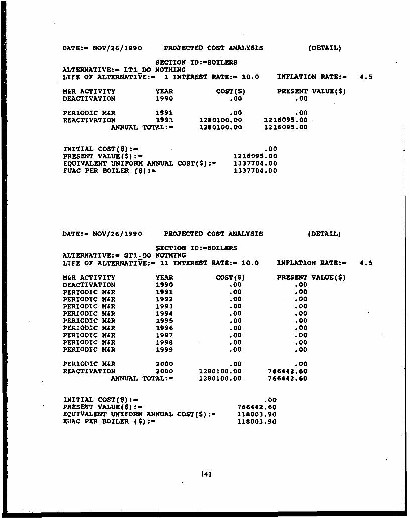
DATE:- NOV/26/1990 PROJECTED COST ANALYSIS (DETAIL)
SECTION ID:-BOILERSALTERNATIVE:- LT1_DO NOTHINGLIFE OF ALTERNATIVE:- 1 INTEREST RATE:- 10.0 INFLATION RATE:- 4.5
M&R ACTIVITY YEAR COST(S) PRESENT VALUE($)DEACTIVATION 1990 .00 .00
PERIODIC M&R 1991 .00 .00REACTIVATION 1991 1280100.00 1216095.00
ANNUAL TOTAL:- 1280100.00 1216095.00
INITIAL COST(S):- .00
PRESENT VALUE(S):- 1216095.00EQUIVALENT UNIFORM ANNUAL COST(S):- 1337704.00EUAC PER BOILER ($):- 1337704.00
DATE:- NOV/26/1990 PROJECTED COST ANALYSIS (DETAIL)
SECTION ID:-BOILERSALTTERNATIVE:- GT1.DO NOTHINGLIFE OF ALTERNATIVE:- 11 INTEREST RATE:- 10.0 INFLATION RATE:- 4.5
M&R ACTIVITY YEAR COST(S) PRESENT VALUE(S)DEACTIVATION 1990 .00 .00PERIODIC M&R 1991 .00 .00PERIODIC M&R 1992 .00 .00PERIODIC M&R 1993 .00 .00PERIODIC M&R 1994 .00 .00PERIODIC M&R 1995 .00 .00PERIODIC M&R 1996 .00 .00PERIODIC M&R 1997 .00 .00PERIODIC M&R 1998 .00 .00PERIODIC f&R 1999 .00 .00
PERIODIC M&R 2000 .00 .00REACTIVATION 2000 1280100.00 766442.60
ANNUAL TOTAL:- 1280100.00 766442.60
INITIAL COST(S):- .00PRESENT VALUE(S):- 766442.60EQUIVALENT UNIFORM ANNUAL COST(S):- 118003.90EUAC PER BOILER (5):- 118003.90
141

ABBREVIATIONS
A/E architectural/engineers
ADP automatic data processing
AHU air-handler unit
AMC U.S. Army Materiel Command
ANSI American National Standards Institute
AR Army Regulation
ARMA Asphalt Roofing Manufacturers Association
ASHRAE American Society of Heating, Refrigerating and Air-Conditioning Engineers
BUR built-up roof
CFC chlorofluorocarbon
DEH Directorate of Engineering and Housing
DOD Department of Defense
DTMF dual-tone multifrequency
DX direct expansion
EMCS emergency monitoring and control system
EMS .agineered management system
EPA Environmental Protection Agency
EPDM ethylene-propylene-diene monomer
EPRI Electrical Power Research Institute
ETAC U.S. Force Environmental Technical Applications Center
EUAC Equivalent Uniform Annual Cost
Fed Spec Federal Specification
FID field interface device
FRP fiberglass-reinforced plastic
GPM gallons pcr minute
HSWA Hazardous Solid Waste Amendments
I/I infiltration/inflow
IAQ indoor air quality
IEEE Institute of Electrical and Electronic Engineers
LPI Leak Potential Index
M&R Maintenance and Repair
142

ABBREVIATIONS (Cont'd)
MACOM Major Army Command
MIL Military Specification
MOGAS motor gasoline
MRPM Maintenance Resource Prediction Model
NASA National Aeronatics and Space Administration
NCEL Naval Civil Engineering Laboratory
NEC National Electric Code
NEMA National Electrical Manufacturers Association
NJDEP New Jersey Department of Environmental Protection
NPS National Park Service
NRCA National Roofing Contractors Association
OSHA Occupational Safety and Health Administration
PM preventive maintenance
RCRA Resource Conservation and Recovery Act
SHDP Steam Heat Distribution Program
TM technical manual
TR technical report
TRADOC U.S. Army Training and Doctrine Command
USACERL U.S. Army Construction Engineering Research Laboratory
USAEHSC U.S. Army Engineering and Housing Support Center
UST underground storage tank
143