layout 1 (page 1)corrosioncoatings.com/catalog/pdf/psi/link_seal_selection_guide.pdf · iso quality...
TRANSCRIPT


FeaturesSaves time and money...
Link-Seal modular seals install in up to 75% less time
compared to lead-oakum joints, hand fitted flashings,
mastics or casing boots.
Positive hydrostatic seal...
Link-Seal modular seals are rated at 20 psig (40 feet of
head), which exceeds the performance requirements of
most applications.
Long seal life...
Link-Seal modular seals are designed for use as a
permanent seal. Seal elements are specially compound-
ed to resist aging and attack from ozone, sunlight, water
and a wide range of chemicals.
Maximum protection against corrosion...
Standard fasteners have a two-part zinc dichromate and
proprietary corrosion inhibiting coating. Corrosion
resistant 316 stainless steel available for maximum corro-
sion protection.
Certification/Approvals...
Factory Mutual Fire Approvals. Also a wide variety of
approvals from various Federal agencies, associations,
code groups, laboratories and organizations.
ISO Quality Assurance...
Link-Seal modular seals are manufactured in an ISO
9001:2000 certified facility.
Configure a Link-Seal modular seal to match your
application...
Color coded EPDM, Nitrile, & Silicone elastomers may
be used with various hardware options to match
performance characteristics with service conditions.
A combination of Century-Line® Sleeves and Link-Seal® Modular Sealsperform a “No Leak Solution” for this pump room application.
Page 1
Certificate No. NACB7895 Certificate No. 10125
Link-Seal®
modular seals are
considered to be
the premier
method for perma-
nently sealing pipes of
any size passing through
walls, floors and ceilings. In
fact, any cylindrical object may be quickly,
easily and permanently sealed, as they
pass through barriers, by the patented
Link-Seal modular seal design.
Ductile iron, concrete, metal as well as
plastic pipes may be hydrostatically sealed
within walls to hold up to 20 psig (40 feet
of static head).
Electrical or telecommunications cable
may be sealed within conduit as they enter
vaults or manholes. The annular space
between carrier pipes passing through cas-
ings may be sealed against the entry of
water, soil or backfill material.
With a wide variety of hardware/
elastomer combinations, Link-Seal
modular seals are easily configured to
achieve the best possible match for
service conditions encountered. High tem-
perature seals, fire seals (Factory Mutual
Approved) and oil resistant seals may be
ordered to meet special or unique service
applications.
For the system approach, metal or non-
conductive Century-Line® sleeves with
water stops may be ordered with Link-Seal
modular seals to ensure correct positioning
and a water tight seal of the
installation within poured concrete walls.
This brochure focuses on standard size
Link-Seal modular seals for use with
Century-Line® Model CS sleeves, Model
WS (Steel) sleeves or core drilled holes.
Link-Seal modular seals are also available
for a wide variety of special applications,
temperature extremes, exotic chemical
combinations and for “out of round” or
non-centered applications.
Please contact factory for
your special application.

Model “C or L” Link-Seal Modular Seals
Suitable for use in water, direct ground burial and
atmospheric conditions. Provides electrical isola-
tion where cathodic protection is required.
Type: Standard
Seal Element: EPDM (Black) or EPDM (Blue)
Pressure Plates: Reinforced Nylon Polymer
Bolts & Nuts: Steel with 2-part Zinc Dichromate
& proprietary corrosion inhibiting coating.
Temp. Range: -40 to +250ºF (-40 to +121ºC)*
Model “S-316” Link-Seal Modular Seals
For chemical processing & waste water treat-
ment. EPDM rubber is resistant to most inorganic
acids and alkalis, some organic chemicals (ace-
tone, alcohol, ketones).
Type: Stainless
Seal Element: EPDM (Black) or EPDM (Blue)
Pressure Plates: Reinforced Nylon Polymer
Bolts & Nuts: 316 Stainless Steel
Temp. Range: -40 to +250ºF (-40 to +121ºC)*
Model “O” Link-Seal Modular Seals
Nitrile rubber is resistant to oils, fuel and many
solvents (gasoline, motor oil, kerosene, methane,
jet fuel, hydraulic fluid, water, etc.)
Type: Oil Resistant
Seal Element: Nitrile (Green) Note: Not U.V. resistant.
Pressure Plates: Reinforced Nylon Polymer
Bolts & Nuts: Steel with 2-part Zinc Dichromate
& proprietary corrosion inhibiting coating.
Temp. Range: -40 to +210ºF (-40 to +99ºC)*
Model “OS-316” Link-Seal Modular Seals
Combination of oil resistant rubber and stainless
steel hardware.
Type: Oil Resistant
Seal Element: Nitrile (Green) Note: Not U.V. resistant.
Pressure Plates: Reinforced Nylon Polymer
Bolts & Nuts: 316 Stainless Steel
Temp. Range: -40 to +210 ºF (-40 to +99ºC)*
Model “T” Link-Seal Modular Seals
Silicone rubber is ideal for temperature
extremes. “T” model is one-hour Factory Mutual
approved.
Type: High/Low Temperature
Seal Element: Silicone (Grey)
Pressure Plates: Steel Zinc Dichromate
Bolts: Steel with 2-part Zinc Dichromate
& proprietary corrosion inhibiting coating.
Temp. Range: -67 to +400ºF (-55 to +204ºC)*
Model “FD/FS” Link-Seal Modular Seals
Double seal for added protection.
Type: Fire Seals
Seal Element: Silicone (Grey)
Pressure Plates: Steel Zinc Dichromate
Bolts: Steel with 2-part Zinc Dichromate
& proprietary corrosion inhibiting coating.
Temp. Range: -67 to +400ºF (-55 to +204ºC)*
Century-Line® Model CS Sleeves are idealfor poured wall construction. Made of HDPEthermoplastic, they are lightweight and easy tohandle. Molded-in waterstop and reinforcingribs serve to anchor the sleeve in the wall andresist pour forces. Nailer end caps are providedto make placement in forms simple and accu-rate. Sleeves are available in 16 diameters, upto 25”, and any length. In the event of a fieldchange they can be shortened with ordinaryhand tools.
Model WS Steel Sleeves are made fromheavy-wall welded or seamless pipe. A full cir-cle waterstop plate acts as positive water sealand anchor to prevent thrust movement. The 2”collar (water-stop) is continuously welded onboth sides. Model WS is available in a widerange of diameters and any length. Sleevesare protected by a coating of red primer. Hotdip galvanizing is available on request.
Link-Seal Modular Seals are also commonlyinstalled in cored wall openings or pre-castopenings such as those formed by use of Cell-Cast® Disks for pipe penetration hole forms.See Cell-Cast Disk (page 4) or contact PSI formore information.
Link-Seal® Modular Seal Options Sleeve Options
with EPDM Seal Elements
with Nitrile Seal Elements
with Silicone Seal Elements
Page 2
*Note: Sustains a constant temp. of 325ºF.
(163ºC.) = Sustained operation near temperature
limits may affect life expectancy.
* = Sustained operation near temperature limits may affect lifeexpectancy.
* = Sustained operation near temperature limits may affect lifeexpectancy.
Silicone (Grey)
Nitrile (Green)
EPDM (Black Seal
Elements)
EPDM (Blue Seal Elements)
Note: Model “L” (Blue) is a lowdurometer EPDM rubber for thin
walled pipe applications

Century-Line® SleevesModel CS (16” length)
Weights and Dimensional DataMODEL I.D. (In.) I.D. (mm) lbs. Kg.
CS-2 1.98 50.3 0.70 0.32
CS-3 2.94 74.7 1.30 0.59
CS-3-1/2 3.38 85.9 1.50 0.68
CS-4 4.03 102.4 2.00 0.90
CS-5 5.14 130.6 2.80 1.27
CS-6 6.14 156.0 3.60 1.63
CS-8 8.21 208.5 4.80 2.18
CS-10 10.19 258.8 6.40 2.90
CS-12 12.26 311.4 7.20 3.27
CS-14 14.14 359.2 11.20 5.08
CS-16 16.18 411.0 12.00 5.44
CS-18 17.45 443.2 15.50 7.03
CS-20 19.12 485.6 17.50 7.94
CS-22 20.32 516.1 21.00 9.53
CS-24 22.76 578.1 22.00 9.98
CS-25 24.81 630.2 23.00 10.43
Century-Line® Pipe Penetration Sleevesare used to create circular sleeved holes in concrete poured
barriers including; walls, floors, ceilings, structural supports
and tank footings. Molded from non-conductive, high impact
resistant HDPE, Century-Line® sleeves are lightweight and
easily installed by one construction worker. They are available
in 16 diameters ranging from 2” to 25” and shipped,
from stock, in any desired length.
Features16 sizes
2” to 25” in diameter.In the event of a field or engineering
change, sleeves may be cut shorter at
the job site using ordinary hand tools
(See page 9). Standard sleeves are
16” (40.6mm) in length. Longer length models may
also be quickly fabricated as a custom ordered item.
1/8 the weight of steel.Century-Line sleeves are light enough for one worker to install with-
out a crane, hoist or helper which reduces installation time and
costs. Century-Line sleeves are easy to stock and store and far less
expensive to ship, when compared to steel sleeves.
Resists water migration.The 2” (50.8mm) water stop collar not only anchors the sleeve in
position but creates a long tortuous path against the migration of
water around the outside of the sleeve.
Adjusts to wall thickness.Century-Line sleeves’ unique hollow water stop collar acts like an
expansion joint, adjusting (up to 1/2” - 12.7mm) to the thickness of
the wall. This compressive force reacts against the forms like a
spring, creating a prevailing tension which maintains proper sleeve
location within the form.
Nailer end caps position sleeve precisely in form.Specially designed end caps provide an ideal method for attaching
Century-Line sleeves to the concrete forms. The end caps assure
that the sleeve holds its circular configuration during the pour. In
addition to keeping out wet concrete, they also prevent dirt
from entering the sleeve during backfill operations or the
interim construction period.
Tough high density polyethylene
(HDPE) construction.High impact-resistant HDPE also provides excellent
resistance to acids, alkalis and other organic sol-
vents. Ideal for cathodic protection sys-
tems, these non-conductive sleeves will
neither rust, corrode or degrade. Low-
temperature properties are such that they
may be installed under any weather con-
ditions suitable for pouring concrete. High
temperature application limit is 150º F. (66º
C.). The sleeve is molded with a texture on
the outside surface to assure a better bond,
than most other plastics, to concrete interfaces.
The system is the solutionCentury-Line® sleeves are engineered to
mate with Link-Seal® modular mechanical
seals for a lifetime of leak-proof perform-
ance.
PSI/Thunderline/Link-Seal® is your one-
stop source for everything you need to
effectively seal the annular space
between pipes and concrete
barriers through which they
pass. Charts on the follow-
ing pages provide Century-
Line® sleeve model numbers
for standard size pipe along with
corresponding Link-Seal® modular
seal model numbers.
Nailer End Cap
Water Stop Collar
Reinforcing Ribs
Nailer End Cap
Page 3
Note: Swimming pool and floor applications, please specify exact lenghts
when ordering. Typically, a form is not installed on the top of a pool or floor,
the CS sleeve water stop will not compress in these applications.

Cell-Cast® Hole Forming Disks
FeaturesEconomy
• Reduces material costs by 30% to 50%.
• Cuts labor costs by 50% - 70%.
• Minimizes freight and handling charges.
Quality
• Consistently produces dimensionally
accurate openings.
• Sized to work with Link-Seal Modular Seals.
• Avoids potential leak path between sleeve and
concrete.
Installation
• Lightweight - 1/8 the weight of steel pipe sleeves.
• Complete assembly accomplished in minutes.
• Easily installed by one construction worker.
Availability
• Cell-Cast® Disks are stocked in a variety of diameters up
to 64.75” (164cm) and available for immediate delivery.
• Larger sizes are available by special order.
Flexibility
• Cell-Cast® Disks are produced in 3” and 4” thicknesses
and can be assembled to fit virtually any wall.
For example:
• Combine two 3” cells and one 4” cell for 10” walls.
• Combine two 4” cells and one 3” cell for 11” walls.
• Combine three 4” cells for 12” walls.
Cell-Cast® Hole Forming Disks - Model CC
Weights and Dimensional DataCELL-CAST® HOLE 3” THICKNESS 4” THICKNESSMODEL NO. I.D. lbs. KG lbs. KG
CC-30 29.25 10.0 4.53 10.4 4.71
CC-32 31.13 10.8 4.89 11.2 5.08
CC-36 34.75 12.6 5.71 13.1 5.94
CC-38 37.25 13.9 6.30 14.4 6.53
CC-42 41.38 16.3 7.39 16.8 7.62
CC-44 43.75 17.7 8.02 18.3 8.30
CC-48 47.25 20.0 9.07 20.7 9.38
CC-50 50.00 22.0 9.97 22.6 10.25
CC-54 52.63 23.9 10.84 24.6 11.15
CC-56 56.00 26.5 12.02 27.3 12.38
CC-60 59.25 29.2 13.24 30.0 13.60
CC-64 62.75 32.2 14.60 33.1 15.01
CC-66 64.75 34.0 15.42 34.9 15.83
Cell-Cast® Hole Forming Disks are
designed to produce large diameter holes
in poured concrete structures. Molded
from HDPE plastic, Cell-Cast®
disks are lightweight and may be installed
by one construction worker. They are available
in a wide variety of diameters.
Disks are either 3” or 4” thick allowing one to
form a hole in 3” walls or thicker (except 5”).
Page 4
WS Steel Wall SleevesModel WS (12” length)
MODEL I.D. lbs. Kg.
WS-2-21-S-12 1.94 5.90 2.67
WS-2-15-S-12 2.07 5.53 2.51
WS-2-1/2-27-S-12 2.32 9.78 4.43
WS-2-1/2-20-S-12 2.47 7.91 3.58
WS-3-30-S-12 2.90 12.60 5.71
WS-3-21-S-12 3.07 9.93 4.51
WS-3-1/2-22-S-12 3.55 11.70 5.31
WS-4-23-S-12 4.03 13.61 6.17
WS-5-25-S-12 5.05 17.91 8.12
WS-6-28-S-12 6.07 22.73 10.31
ws-6-18-S-12 6.25 14.82 6.72
WS-8-32-S-12 7.98 33.55 15.22
ws-8-18-S-12 8.25 21.94 9.95
WS-10-36-S-12 10.02 46.12 20.92
ws-10-25-S-12 10.25 33.67 15.27
WS-12-37-S-12 12.00 60.14 27.28
WS-14-37-S-12 13.25 62.04 28.14
WS-16-37-S-12 15.25 71.04 32.22
WS-18-37-S-12 17.25 79.98 36.28
WS-20-37-S-12 19.25 90.00 40.82
WS-22-37-S-12 21.25 98.00 44.45
WS-24-37-S-12 23.25 107.00 48.53
WS Wall Sleeves are constructed
from steel and available in
a wide range of diameters
and lengths.
They are an excellent
choice for installations where
the Link-Seal® Modular Seal
and WS sleeve assembly would
be subject to extremely high temperatures
or where fire seals are specified.Note: WS sizes thru. 10” are schedule 40.
WS sizes 12” and up have a standard .375”
wall thickness. ws rolled sleeves (6” & 8”) =
.1875” wall thickness; (10”) = .25” wall thickness.
How To Order
Please see Page 5 for ordering information
on Link-Seal® modular seals and WS Steel
Sleeves. For diameters larger than 24”,
2” Steel Water Stop.
Continous Weld-Bead
on both sides.
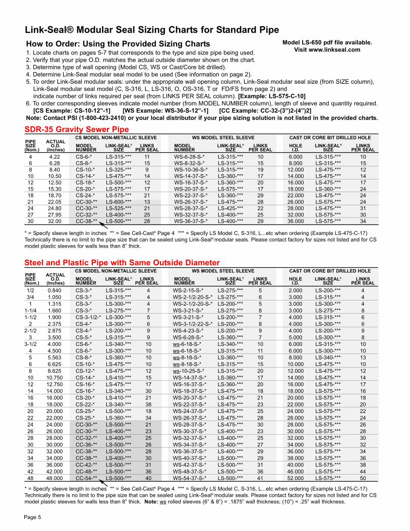
How to Order: Using the Provided Sizing Charts1. Locate charts on pages 5-7 that corresponds to the type and size pipe being used.
2. Verify that your pipe O.D. matches the actual outside diameter shown on the chart.
3. Determine type of wall opening (Model CS, WS or Cast/Core bit drilled).
4. Determine Link-Seal modular seal model to be used (See information on page 2).
5. To order Link-Seal modular seals: under the appropriate wall opening column, Link-Seal modular seal size (from SIZE column),
Link-Seal modular seal model (C, S-316, L, LS-316, O, OS-316, T or FD/FS from page 2) and
indicate number of links required per seal (from LINKS PER SEAL column). [Example: LS-575-C-10]
6. To order corresponding sleeves indicate model number (from MODEL NUMBER column), length of sleeve and quantity required.
[CS Example: CS-10-12”-1] [WS Example: WS-36-S-12”-1] [CC Example: CC-32-(3”)2-(4”)2]
Note: Contact PSI (1-800-423-2410) or your local distributor if your pipe sizing solution is not listed in the provided charts.
Link-Seal® Modular Seal Sizing Charts for Standard Pipe
Page 5
Steel and Plastic Pipe with Same Outside DiameterCS MODEL NON-METALLIC SLEEVE WS MODEL STEEL SLEEVE CAST OR CORE BIT DRILLED HOLE
PIPE ACTUALSIZE O.D. MODEL LINK-SEAL® LINKS MODEL LINK-SEAL® LINKS HOLE LINK-SEAL® LINKS(Nom.) (Inches) NUMBER SIZE PER SEAL NUMBER SIZE PER SEAL I.D. SIZE PER SEAL
1/2 0.840 CS-3-* LS-315-*** 4 WS-2-15-S-* LS-275-*** 5 2.000 LS-200-*** 4
3/4 1.050 CS-3-* LS-315-*** 4 WS-2-1/2-20-S-* LS-275-*** 6 3.000 LS-315-*** 4
1 1.315 CS-3-* LS-300-*** 4 WS-2-1/2-20-S-* LS-200-*** 5 3.000 LS-300-*** 4
1-1/4 1.660 CS-3-* LS-275-*** 7 WS-3-21-S-* LS-275-*** 8 3.000 LS-275-*** 8
1-1/2 1.900 CS-3-1/2-* LS-300-*** 5 WS-3-21-S-* LS-200-*** 7 4.000 LS-315-*** 6
2 2.375 CS-4-* LS-300-*** 6 WS-3-1/2-22-S-* LS-200-*** 8 4.000 LS-300-*** 6
2-1/2 2.875 CS-4-* LS-200-*** 9 WS-4-23-S-* LS-200-*** 9 4.000 LS-200-*** 9
3 3.500 CS-5-* LS-315-*** 9 WS-6-28-S-* LS-360-*** 7 5.000 LS-300-*** 8
3-1/2 4.000 CS-6-* LS-340-*** 10 ws-6-18-S-* LS-340-*** 10 6.000 LS-315-*** 10
4 4.500 CS-6-* LS-300-*** 10 ws-6-18-S-* LS-315-*** 11 6.000 LS-300-*** 10
5 5.563 CS-8-* LS-360-*** 10 ws-8-18-S-* LS-360-*** 10 8.000 LS-340-*** 13
6 6.625 CS-10-* LS-475-*** 10 ws-8-18-S-* LS-315-*** 15 10.000 LS-475-*** 10
8 8.625 CS-12-* LS-475-*** 12 ws-10-25-S-* LS-315-*** 20 12.000 LS-475-*** 12
10 10.750 CS-14-* LS-410-*** 15 WS-14-37-S-* LS-360-*** 17 14.000 LS-475-*** 14
12 12.750 CS-16-* LS-475-*** 17 WS-16-37-S-* LS-360-*** 20 16.000 LS-475-*** 17
14 14.000 CS-16-* LS-340-*** 30 WS-18-37-S-* LS-475-*** 18 18.000 LS-575-*** 16
16 16.000 CS-20-* LS-410-*** 21 WS-20-37-S-* LS-475-*** 21 20.000 LS-575-*** 18
18 18.000 CS-22-* LS-340-*** 38 WS-22-37-S-* LS-475-*** 23 22.000 LS-575-*** 20
20 20.000 CS-25-* LS-500-*** 18 WS-24-37-S-* LS-475-*** 25 24.000 LS-575-*** 22
22 22.000 CS-25-* LS-360-*** 34 WS-26-37-S-* LS-475-*** 28 26.000 LS-575-*** 24
24 24.000 CC-30-** LS-500-*** 21 WS-28-37-S-* LS-475-*** 30 28.000 LS-575-*** 26
26 26.000 CC-30-** LS-400-*** 23 WS-30-37-S-* LS-400-*** 23 30.000 LS-575-*** 28
28 28.000 CC-32-** LS-400-*** 25 WS-32-37-S-* LS-400-*** 25 32.000 LS-575-*** 30
30 30.000 CC-36-** LS-500-*** 26 WS-34-37-S-* LS-400-*** 27 34.000 LS-575-*** 32
32 32.000 CC-38-** LS-500-*** 28 WS-36-37-S-* LS-400-*** 29 36.000 LS-575-*** 34
34 34.000 CC-38-** LS-400-*** 30 WS-40-37-S-* LS-500-*** 29 38.000 LS-575-*** 36
36 36.000 CC-42-** LS-500-*** 31 WS-42-37-S-* LS-500-*** 31 40.000 LS-575-*** 38
42 42.000 CC-48-** LS-500-*** 36 WS-48-37-S-* LS-500-*** 36 46.000 LS-575-*** 44
48 48.000 CC-54-** LS-500-*** 40 WS-54-37-S-* LS-500-*** 41 52.000 LS-575-*** 50
SDR-35 Gravity Sewer PipeCS MODEL NON-METALLIC SLEEVE WS MODEL STEEL SLEEVE CAST OR CORE BIT DRILLED HOLE
PIPE ACTUALSIZE O.D. MODEL LINK-SEAL® LINKS MODEL LINK-SEAL® LINKS HOLE LINK-SEAL® LINKS(Nom.) (Inches) NUMBER SIZE PER SEAL NUMBER SIZE PER SEAL I.D. SIZE PER SEAL
4 4.22 CS-6-* LS-315-*** 11 WS-6-28-S-* LS-315-*** 10 6.000 LS-315-*** 10
6 6.28 CS-8-* LS-315-*** 15 WS-8-32-S-* LS-315-*** 15 8.000 LS-315-*** 15
8 8.40 CS-10-* LS-325-*** 9 WS-10-36-S-* LS-315-*** 19 12.000 LS-475-*** 12
10 10.50 CS-14-* LS-475-*** 14 WS-14-37-S-* LS-360-*** 17 14.000 LS-475-*** 14
12 12.50 CS-18-* LS-500-*** 12 WS-16-37-S-* LS-360-*** 20 16.000 LS-475-*** 17
15 15.30 CS-20-* LS-575-*** 17 WS-20-37-S-* LS-575-*** 17 18.000 LS-360-*** 24
18 18.70 CS-24-* LS-575-*** 21 WS-22-37-S-* LS-360-*** 29 22.000 LS-475-*** 24
21 22.05 CC-30-** LS-600-*** 13 WS-26-37-S-* LS-475-*** 28 26.000 LS-575-*** 24
24 24.80 CC-30-** LS-525-*** 21 WS-28-37-S-* LS-425-*** 22 28.000 LS-475-*** 31
27 27.95 CC-32-** LS-400-*** 25 WS-32-37-S-* LS-400-*** 25 32.000 LS-575-*** 30
30 32.00 CC-38-** LS-500-*** 28 WS-36-37-S-* LS-400-*** 29 36.000 LS-575-*** 34
* = Specify sleeve length in inches ** = See Cell-Cast® Page 4 *** = Specify LS Model C, S-316, L...etc when ordering (Example LS-475-C-17)
Technically there is no limit to the pipe size that can be sealed using Link-Seal® modular seals. Please contact factory for sizes not listed and for CS
model plastic sleeves for walls less than 8” thick.
* = Specify sleeve length in inches ** = See Cell-Cast® Page 4 *** = Specify LS Model C, S-316, L...etc when ordering (Example LS-475-C-17)
Technically there is no limit to the pipe size that can be sealed using Link-Seal® modular seals. Please contact factory for sizes not listed and for CS
model plastic sleeves for walls less than 8” thick. Note: ws rolled sleeves (6” & 8”) = .1875” wall thickness; (10”) = .25” wall thickness.
Model LS-650 pdf file available.
Visit www.linkseal.com

Page 6
* = Specify sleeve length in inches *** = Specify LS Model C, S-316, L...etc when ordering (Example LS-475-C-17). Technically there is no limit to
the pipe size that can be sealed using Link-Seal® modular seals. Please contact factory for sizes
not listed and for CS model plastic sleeves for walls less than 8” thick.
Note: ws rolled sleeves (6” & 8”) = .1875” wall thickness; (10”) = .25” wall thickness.
Copper TubingCS MODEL NON-METALLIC SLEEVE WS MODEL STEEL SLEEVE CAST OR CORE BIT DRILLED HOLE
PIPE ACTUALSIZE) O.D. MODEL LINK-SEAL® LINKS MODEL LINK-SEAL® LINKS HOLE LINK-SEAL® LINKS
(Nom.) (Inches) NUMBER SIZE PER SEAL NUMBER SIZE PER SEAL I.D. SIZE PER SEAL
1/2 0.625 CS-2-* LS-275-*** 4 WS-2-15-S-* LS-275-*** 5 2.000 LS-275-*** 4
3/4 0.875 CS-3-* LS-315-*** 4 WS-2-1/2-20-S-* LS-275-*** 6 2.000 LS-200-*** 4
1 1.125 CS-3-* LS-314-*** 4 WS-2-1/2-20-S-* LS-275-*** 6 3.000 LS-315-*** 4
1-1/4 1.375 CS-3-* LS-275-*** 8 WS-2-1/2-20-S-* LS-200-*** 5 3.000 LS-300-*** 4
1-1/2 1.625 CS-3-* LS-275-*** 8 WS-3-21-S-* LS-275-*** 8 3.000 LS-275-*** 8
2 2.125 CS-4-* LS-315-*** 6 WS-3-1/2-22-S-* LS-275-*** 10 4.000 LS-315-*** 6
2-1/2 2.625 CS-4-* LS-275-*** 12 WS-4-23-S-* LS-275-*** 11 4.000 LS-275-*** 11
3 3.125 CS-5-* LS-340-*** 8 WS-5-25-S-* LS-315-*** 8 5.000 LS-315-*** 8
4 4.125 CS-5-* LS-200-*** 12 ws-6-18-S-* LS-340-*** 10 6.000 LS-315-*** 10
6 6.125 CS-8-* LS-340-*** 14 ws-8-18-S-* LS-340-*** 14 8.000 LS-315-*** 15
8 8.125 CS-12-* LS-575-*** 10 ws-10-25-S-* LS-340-*** 18 12.000 LS-575-*** 10
10 10.125 CS-12-* LS-340-*** 22 WS-14-37-S-* LS-410-*** 14 14.000 LS-575-*** 12
12 12.125 CS-16-* LS-575-*** 14 WS-16-37-S-* LS-410-*** 16 16.000 LS-575-*** 14
Cast Iron Soil Pipe (Extra Heavy)CS MODEL NON-METALLIC SLEEVE WS MODEL STEEL SLEEVE CAST OR CORE BIT DRILLED HOLE
PIPE ACTUALSIZE O.D. MODEL LINK-SEAL® LINKS MODEL LINK-SEAL® LINKS HOLE LINK-SEAL® LINKS
(Nom.) (Inches) NUMBER SIZE PER SEAL NUMBER SIZE PER SEAL I.D. SIZE PER SEAL
2 2.380 CS-4-* LS-300-*** 6 WS-3-1/2-22-S-* LS-200-*** 8 4.000 LS-300-*** 6
3 3.500 CS-5-* LS-315-*** 9 WS-6-28-S-* LS-360-*** 7 5.000 LS-300-*** 8
4 4.500 CS-6-* LS-300-*** 10 ws-6-18-S-* LS-315-*** 11 6.000 LS-300-*** 10
5 5.500 CS-8-* LS-360-*** 10 ws-8-18-S-* LS-360-*** 10 8.000 LS-340-*** 13
6 6.500 CS-8-* LS-315-*** 15 ws-8-18-S-* LS-315-*** 15 10.000 LS-475-*** 10
8 8.620 CS-12-* LS-475-*** 12 ws-10-25-S-* LS-315-*** 20 12.000 LS-475-*** 12
10 10.750 CS-14-* LS-410-*** 15 WS-14-37-S-* LS-360-*** 17 14.000 LS-475-*** 14
12 12.750 CS-16-* LS-475-*** 17 WS-16-37-S-* LS-360-*** 20 16.000 LS-475-*** 17
15 15.880 CS-20-* LS-410-*** 21 WS-20-37-S-* LS-475-*** 20 18.000 LS-340-*** 33
Ductile Iron Pipe (AWWA-C900, AWWA-C905, PVC Water Pipe)CS MODEL NON-METALLIC SLEEVE WS MODEL STEEL SLEEVE CAST OR CORE BIT DRILLED HOLE
PIPE ACTUALSIZE O.D. MODEL LINK-SEAL® LINKS MODEL LINK-SEAL® LINKS HOLE LINK-SEAL® LINKS(Nom.) (Inches) NUMBER SIZE PER SEAL NUMBER SIZE PER SEAL I.D. SIZE PER SEAL
2 2.500 CS-4-* LS-300-*** 6 WS-3-1/2-22-S-* LS-200-*** 8 4.000 LS-300-*** 6
2-1/4 2.750 CS-4-* LS-275-*** 10 WS-4-23-S-* LS-200-*** 9 4.000 LS-200-*** 9
3 3.960 CS-6-* LS-340-*** 10 ws-6-18-S-* LS-340-*** 10 6.000 LS-315-*** 10
4 4.800 CS-8-* LS-475-*** 8 ws-8-18-S-* LS-475-*** 8 8.000 LS-410-*** 7
6 6.900 CS-10-* LS-475-*** 10 WS-10-36-S-* LS-410-*** 10 10.000 LS-410-*** 10
8 9.050 CS-12-* LS-400-*** 9 WS-12-37-S-* LS-400-*** 9 12.000 LS-400-*** 9
10 11.100 CS-14-* LS-410-*** 15 WS-14-37-S-* LS-340-*** 24 14.000 LS-410-*** 15
12 13.200 CS-18-* LS-575-*** 15 WS-16-37-S-* LS-340-*** 28 16.000 LS-400-*** 12
14 15.300 CS-20-* LS-575-*** 17 WS-20-37-S-* LS-575-*** 17 18.000 LS-360-*** 24
16 17.400 CS-22-* LS-360-*** 28 WS-22-37-S-* LS-575-*** 19 20.000 LS-360-*** 27
18 19.500 CS-24-* LS-410-*** 25 WS-24-37-S-* LS-575-*** 21 22.000 LS-360-*** 30
20 21.600 CS-25-* LS-400-*** 20 WS-26-37-S-* LS-575-*** 23 26.000 LS-525-*** 19
24 25.800 CC-30-** LS-400-*** 23 WS-30-37-S-* LS-400-*** 23 28.000 LS-425-*** 23
30 32.000 CC-38-** LS-500-*** 28 WS-36-37-S-* LS-400-*** 29 36.000 LS-575-*** 34
36 38.300 CC-44-** LS-500-*** 33 WS-44-1/2-37-S-* LS-500-*** 33 43.000 LS-500-*** 33
42 44.500 CC-50-** LS-500-*** 38 WS-50-37-S-* LS-500-*** 38 49.000 LS-525-*** 38
48 50.800 CC-56-** LS-500-*** 43 WS-57-37-S-* LS-500-*** 43 56.000 LS-500-*** 43
* = Specify sleeve length in inches ** = See Cell-Cast® Page 4 *** = Specify LS Model C, S-316, L...etc when ordering (Example LS-475-C-17)
Technically there is no limit to the pipe size that can be sealed using Link-Seal® modular seals. Please contact factory for sizes not listed and for CS
model plastic sleeves for walls less than 8” thick. Note: ws rolled sleeves (6” & 8”) = .1875” wall thickness; (10”) = .25” wall thickness.
Cast Iron Soil Pipe (Service Weight)CS MODEL NON-METALLIC SLEEVE WS MODEL STEEL SLEEVE CAST OR CORE BIT DRILLED HOLE
PIPE ACTUALSIZE O.D. MODEL LINK-SEAL® LINKS MODEL LINK-SEAL® LINKS HOLE LINK-SEAL® LINKS
(Nom.) (Inches) NUMBER SIZE PER SEAL NUMBER SIZE PER SEAL I.D. SIZE PER SEAL
2 2.300 CS-4-* LS-315-*** 6 WS-4-23-S-* LS-315-*** 6 4.000 LS-315-*** 6
3 3.300 CS-5-* LS-315-*** 9 WS-6-28-S-* LS-360-*** 7 5.000 LS-315-*** 8
4 4.300 CS-6-* LS-315-*** 11 WS-6-28-S-* LS-315-*** 10 6.000 LS-315-*** 10
5 5.300 CS-8-* LS-410-*** 8 ws-8-18-S-* LS-410-*** 8 8.000 LS-360-*** 9
6 6.300 CS-8-* LS-315-*** 15 WS-8-32-S-* LS-315-*** 15 8.000 LS-315-*** 15
8 8.380 CS-10-* LS-325-*** 9 WS-10-36-S-* LS-315-*** 19 10.000 LS-315-*** 19
10 10.500 CS-14-* LS-475-*** 14 WS-14-37-S-* LS-360-*** 17 14.000 LS-475-*** 14
12 12.500 CS-18-* LS-500-*** 12 WS-16-37-S-* LS-360-*** 20 16.000 LS-475-*** 17
15 15.620 CS-20-* LS-475-*** 20 WS-20-37-S-* LS-475-*** 20 18.000 LS-425-*** 14
* = Specify sleeve length in inches *** = Specify LS Model C, S-316, L...etc when ordering (Example LS-475-C-17)
* = Specify sleeve length in inches *** = Specify LS Model C, S-316, L...etc when ordering (Example LS-475-C-17)

Frequently Asked Questions1) Q - Can Link-Seal modular seals
withstand pressures greater than 20
psi?
A - Yes, where pressure exceeds 20
psi, key factors to consider are: pipe
surface, sleeve surface, seal com-
pression, and proper installation tech-
niques. Contact PSI for more informa-
tion.
2) Q - How much angular pipe move-
ment will Link-Seal modular seals
allow and still maintain a seal?
A - Link-Seal modular seals may allow
angular pipe movement or misalign-
ment depending on the ratio of annu-
lar space of the penetration to the
expanded range of the Link-Seal
model sized for the penetration.
Please call PSI for more information.
3) Q - Is it necessary to use WS
or CS sleeves when installing
Link-Seal modular seals?
A - WS model steel and CS model
plastic sleeves are specially designed
for use with Link-Seal modular seals.
When installed with Link-Seal modular
seals these sleeves provide the best
possible assurance of a quality wall
penetration system.
4) Q - Sometimes when installing a
belt of Link-Seal modular seals, it
hangs loose on the pipe even though
all my sizing calculations are correct.
Why does it appear that I have too
many links?
A - Link-Seal modular seals are basi-
cally sized to fit the opening, not the
pipe. Use the assemblies suggested
by the charts or calculation. It may not
look right, but it will fit.
5) Q - Can Link-Seal modular seals be
used for penetrations where the pipe is
off-center to the opening?
A - Centering is very important.
Contact PSI for more information.
6) Q - Is it necessary to use riser
clamps, pipe saddles and hanger sup-
ports with Link-Seal modular seals?
A - Designed as a penetration seaI,
Link-Seal modular seals are not
intended to be a structural support.
Standard pipe hanger practice should
always be applied.
7) Q - What tools are required to install
Link-Seal modular seals?
A - A socket or offset wrench with
5/16”, 1/2”, 3/8”, 9/16”, 3/4” & 1-3/16”
sockets will handle all installations. A
low speed (450 RPM or less) power
tool is suggested for multiple installa-
tions to increase efficiency. (see next
question)
8) Q - Can I use power tools when
installing Link-Seal modular seals with
316 stainless steel bolts?
A - No, please see suggested
installation techniques.
Page 7
Minimum Wall Thickness Required for
Link-Seal® Modular SealsMODEL NO. MINIMUM
WALL THICKNESS
LS-200/LS-275 2.25”
LS-300/LS-315 3.00”
LS-325/LS-340/LS-360 4.00”
LS-400/LS-410/LS-425/LS-475 5.00”
LS-500/LS-525/LS-575 5.00”
LS-600 6.00”
Rigid (RSC), Aluminum (ASC), Galvanized (GSC), Non-Metallic Conduit (NRC)CS MODEL NON-METALLIC SLEEVE WS MODEL STEEL SLEEVE CAST OR CORE BIT DRILLED HOLE
Conduit ACTUALSIZE O.D. MODEL LINK-SEAL® LINKS MODEL LINK-SEAL® LINKS HOLE LINK-SEAL® LINKS
(Nom.) (Inches) NUMBER SIZE PER SEAL NUMBER SIZE PER SEAL I.D. SIZE PER SEAL
1/2 0.840 CS-3-* LS-315-*** 4 WS-2-15-S-* LS-275-*** 5 2.000 LS-200-*** 4
3/4 1.050 CS-3-* LS-315-*** 4 WS-2-1/2-20-S-* LS-275-*** 6 3.000 LS-315-*** 4
1 1.315 CS-3-* LS-300-*** 4 WS-2-1/2-20-S-* LS-200-*** 5 3.000 LS-300-*** 4
1-1/4 1.660 CS-3-* LS-275-*** 7 WS-3-21-S-* LS-275-** 8 3.000 LS-275-*** 8
1-1/2 1.900 CS-3-1/2-* LS-300-*** 5 WS-3-21-S-* LS-200-*** 7 4.000 LS-315-*** 6
2 2.375 CS-4-* LS-300-*** 6 WS-3-1/2-22-S-* LS-200-** 8 4.000 LS-300-*** 6
2-1/2 2.875 CS-4-* LS-200-*** 9 WS-4-23-S-* LS-200-*** 9 4.000 LS-200-*** 9
3 3.500 CS-5-* LS-315-*** 9 WS-6-28-S-* LS-360-*** 7 5.000 LS-300-*** 8
3-1/2 4.000 CS-6-* LS-340-*** 10 ws-6-18-S-* LS-340-*** 10 6.000 LS-315-*** 10
4 4.500 CS-6-* LS-300-*** 10 ws-6-18-S-* LS-315-*** 11 6.000 LS-300-*** 10
5 5.563 CS-8-* LS-360-*** 10 ws-8-18-S-* LS-360-*** 10 8.000 LS-340-*** 13
6 6.625 CS-10-* LS-475-*** 10 ws-8-18-S-* LS-315-*** 15 10.000 LS-475-*** 10
Electrical Metallic Tubing (EMT) Thin WallCS MODEL NON-METALLIC SLEEVE WS MODEL STEEL SLEEVE CAST OR CORE BIT DRILLED HOLE
Conduit ACTUALSIZE O.D. MODEL LINK-SEAL® LINKS MODEL LINK-SEAL® LINKS HOLE LINK-SEAL® LINKS
(Nom.) (Inches) NUMBER SIZE PER SEAL NUMBER SIZE PER SEAL I.D. SIZE PER SEAL
1/2 0.706 CS-2-* LS-275-*** 4 WS-2-15-S-* LS-275-*** 5 2.000 LS-275-*** 4
3/4 0.922 CS-3-* LS-315-*** 4 WS-2-1/2-20-S-* LS-275-*** 6 2.000 LS-200-*** 4
1 1.163 CS-3-* LS-315-*** 4 WS-2-1/2-20-S-* LS-275-*** 6 3.000 LS-315-*** 4
1-1/4 1.510 CS-3-* LS-275-*** 8 WS-3-30-S-* LS-275-*** 7 3.000 LS-275-*** 8
1-1/2 1.740 CS-3-1/2-* LS-300-*** 5 WS-3-21-S-* LS-275-*** 8 3.000 LS-200-*** 6
2 2.197 CS-4-* LS-315-*** 6 WS-3-1/2-22-S-* LS-275-*** 10 4.000 LS-315-*** 6
2-1/2 2.875 CS-4-* LS-200-*** 9 WS-4-23-S-* LS-200-*** 9 4.000 LS-200-*** 9
3 3.500 CS-5-* LS-315-*** 9 WS-6-28-S-* LS-360-*** 7 5.000 LS-300-*** 8
4 4.500 CS-6-* LS-300-*** 10 ws-6-18-S-* LS-315-*** 11 6.000 LS-300-*** 10
Technically there is no limit to the conduit or pipe size that can be sealed using Link-Seal® modular seals.
Please contact factory for sizes not listed and for CS model plastic sleeves for walls less than 8” thick.
Note: ws rolled sleeves (6” & 8”) = .1875” wall thickness; (10”) = .25” wall thickness.
Intermediate Metal Conduit (IMC)CS MODEL NON-METALLIC SLEEVE WS MODEL STEEL SLEEVE CAST OR CORE BIT DRILLED HOLE
Conduit ACTUALSIZE O.D. MODEL LINK-SEAL® LINKS MODEL LINK-SEAL® LINKS HOLE LINK-SEAL® LINKS
(Nom.) (Inches) NUMBER SIZE PER SEAL NUMBER SIZE PER SEAL I.D. SIZE PER SEAL
1/2 0.815 CS-3-* LS-315-*** 4 WS-2-15-S-* LS-275-*** 5 2.000 LS-200-*** 4
3/4 1.029 CS-3-* LS-315-*** 4 WS-2-1/2-20-S-* LS-275-*** 6 3.000 LS-315-*** 4
1 1.290 CS-3-1/2-* LS-315-*** 5 WS-2-1/2-20-S-* LS-200-*** 5 3.000 LS-300-*** 4
1-1/4 1.638 CS-3-* LS-275-*** 8 WS-3-21-S-* LS-275-*** 8 3.000 LS-275-*** 8
1-1/2 1.883 CS-3-1/2-* LS-300-*** 5 WS-3-21-S-* LS-200-*** 7 4.000 LS-315-*** 6
2 2.360 CS-4-* LS-300-*** 6 WS-3-1/2-22-S-* LS-200-*** 8 4.000 LS-300-*** 6
2-1/2 2.857 CS-4-* LS-200-*** 9 WS-4-23-S-* LS-200-*** 9 4.000 LS-200-*** 9
3 3.476 CS-5-* LS-315-*** 9 WS-6-28-S-* LS-360-*** 7 5.000 LS-300-*** 8
3-1/2 3.970 CS-6-* LS-340-*** 10 ws-6-18-S* LS-340-*** 10 6.000 LS-315-*** 10
4 4.466 CS-6-* LS-315-*** 11 ws-6-18-S-* LS-315-*** 11 6.000 LS-300-*** 10
* = Specify sleeve length in inches *** = Specify LS Model C, S-316, L...etc when ordering (Example LS-475-C-17)
* = Specify sleeve length in inches *** = Specify LS Model C, S-316, L...etc when ordering (Example LS-475-C-17)
If the seal doesn’t appear to be correct using the techniques provided, Call PSI at 713-747-6948 or 800-423-2410.
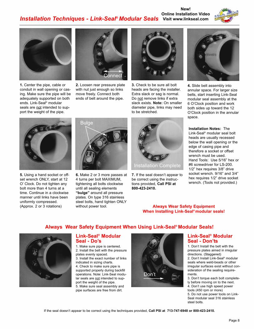
Installation Techniques - Link-Seal® Modular Seals
Installation Notes: The
Link-Seal® modular seal bolt
heads are usually recessed
below the wall opening or the
edge of casing pipe and
therefore a socket or offset
wrench must be used.
Hand Tools: Use 5/16” hex or
#6 screwdriver for LS-200.
1/2” hex requires 3/8” drive
socket wrench. 9/16” and 3/4”
hex requires 1/2” drive socket
wrench. (Tools not provided.)
1. Center the pipe, cable or
conduit in wall opening or cas-
ing. Make sure the pipe will be
adequately supported on both
ends. Link-Seal® modular
seals are not intended to sup-
port the weight of the pipe.
2. Loosen rear pressure plate
with nut just enough so links
move freely. Connect both
ends of belt around the pipe.
3. Check to be sure all bolt
heads are facing the installer.
Extra slack or sag is normal.
Do not remove links if extra
slack exists. Note: On smaller
diameter pipe, links may need
to be stretched.
4. Slide belt assembly into
annular space. For larger size
belts, start inserting Link-Seal
modular seal assembly at the
6 O’Clock position and work
both sides up toward the 12
O’Clock position in the annular
space.
5. Using a hand socket or off-
set wrench ONLY, start at 12
O’ Clock. Do not tighten any
bolt more than 4 turns at a
time. Continue in a clockwise
manner until links have been
uniformly compressed.
(Approx. 2 or 3 rotations)
6. Make 2 or 3 more passes at
4 turns per bolt MAXIMUM,
tightening all bolts clockwise
until all sealing elements
“bulge” around all pressure
plates. On type 316 stainless
steel bolts, hand tighten ONLY
without power tool.
7. If the seal doesn’t appear to
be correct using the instruc-
tions provided, Call PSI at
800-423-2410.
Link-Seal® ModularSeal - Do’s
Link-Seal® ModularSeal - Don’ts
1. Make sure pipe is centered.
2. Install the belt with the pressure
plates evenly spaced.
3. Install the exact number of links
indicated in sizing charts.
4. Check to make sure pipe is
supported properly during backfill
operations. Note: Link-Seal modu-
lar seals are not intended to sup-
port the weight of the pipe.
5. Make sure seal assembly and
pipe surfaces are free from dirt.
1. Don’t Install the belt with the
pressure plates aimed in irregular
directions. (Staggered)
2. Don’t Install Link-Seal® modular
seals where weld-beads or other
irregular surfaces exist without con-
sideration of the sealing require-
ments.
3. Don’t torque each bolt complete-
ly before moving on to the next.
4. Don’t use high speed power
tools (450 rpm or more)
5. Do not use power tools on Link-
Seal modular seal 316 stainless
steel bolts.
Don’t
Always Wear Safety Equipment When Using Link-Seal® Modular Seals!
Always Wear Safety Equipment
When Installing Link-Seal® modular seals!
Connect
Bulge
Installation Complete
Page 8
New!
Online Installation Video
Visit www.linkseal.com

1. Measure the center line to
position Century-Line® Sleeve
end cap.
2. Nail one of the end caps at
the marked center line.
3. Place the Century-Line®
Sleeve on the end cap. The
sleeve and endcaps total
length should be one-fourth
longer than the width of the
wall. Cut with a hand or power
saw. Note: To insure minimum watermigration, center the water stopin wall by cutting equal lengthsfrom each end of the sleeve,except as noted below.
Century-Line® Sleeves are thermoplastic wall or floor pipe penetration sleeves. One person
working alone can usually install a Century-Line® Sleeve regardless of the size.
4. Place second end cap on
sleeve. Check to determine
that the cap is properly insert-
ed.
5. For additional stability, it’s
necessary to secure the
sleeve with wire to the rebar.
Inset the other end cap firmly
and check that second end
cap is positioned correctly and
close the form.
6. After the concrete is poured
and cured, remove end caps
with screw driver or crow bar.
End caps may be replaced to
protect sleeve until pipe pene-
tration is made.
After nailing end cap to form,
drive (threaded rod*) through
the end plate and form and
(thread nut*) on other side.
Note: Remember to measure
the (threaded rod*) to match
the length of the sleeve.
Place the sleeve over the end
cap nailed to the form.
* = Not Provided byPSI.
Place second cap on the
sleeve and use a (block of
wood*) and (wing nut*) to
tighten unit in place. Make
certain sleeve is plumb.
Installation Techniques - Century-Line® Sleeves
Alternative Technique Using Threaded Rod
Wall Cut From Dimension Cut From DimensionThickness Left End A Right End B
16” 0.0” 7.125” 0.0” 7.125”
14” 1.875” 6.125” 1.875” 6.125”
12” 1.875” 5.125” 1.875” 5.125”
10” 2.375” 4.625” 3.375” 3.625”
8” 2.375” 4.625” 5.375” 1.625”
EndCap1/2”
EndCap1/2”
CenterWater Stop
1”A B
Notes:
1. Example: To convert 16” to 12”,
cut 2” off each end.
2. Endcaps leave 1/2” depression
in face of concrete.
3. On sleeves under 12” length,
install Link-Seal® modular seal on
the “long side” of the waterstop.
(a) For Link-Seal® modular seals
models LS-200, LS-275, LS-300,
LS-315, LS-340 and LS-360 -
install with pressure plates flush
with outer edge of the sleeve.
(b) For Link-Seal® modular seals
models LS-325, LS-400, LS-410,
LS-425 and LS-475 - install with
presure plates partially inserted
into the sleeve. When tightened,
the pressure plates will “pull” into
the sleeve.
(c) For Link-Seal® modular seals
models LS-500, LS-525, LS-575
and LS-600 - the minimum sleeve
length is 10”. Follow the instruc-
tions in 3 above.
1/2”
Depression in face of the con-
crete formed by the endcaps.
If you should have questions
using the techniques provided,
Call PSI at 713-747-6948 or
800-423-2410.
Always Wear Safety Equipment When Using
Century-Line Sleeves & Link-Seal Modular Seals!
Always install Link-Sealmodular seals on side A
Page 9
New!
Online Installation Video
Visit www.linkseal.com

Installation Techniques - Cell-Cast® Disks
1. Locate center line where
the hole is desired. This loca-
tion will be used as a guide for
the threaded centering assist
rod.
2. A 2x4 wood nailer is includ-
ed. Fasten it along with the
threaded rod directly to the
concrete form. This provides
support and helps center the
complete Cell-Cast® disk
assembly.
4. Secure the edges of the cell
to the form using the provided
steel spikes.
3. Slide the first Cell-Cast®
disk over the threaded rod.
6. Guide the 1” wood block
over the threaded rod and
secure the assembly with the
wing nut provided.
8. After wall cures, wall forms
are removed. The Cell-Cast®
disk assembly is now ready for
removal.
9. Chip excess concrete from
the edge of the Cell-Cast® disk
assembly and wall.
7. Wrap each seam with one
wrap of 2” wide tape to bridge
any possible gaps. Note: Tape
not included. Finish installing
concrete forms and pour con-
crete.
10. Remove disks by break-
ing out the entire assembly.
11. Inspect the installation. A
smooth opening is important
for a proper Link-Seal®
modular seal installation.
Repair voids and grind
smooth any ridges.
Always Wear Safety Equipment When Using Cell-Cast® Disks!
5. Additional disks are inter-
locked to accommodate fin-
ished wall thickness. Verify
thickness is the same as wall.
If you should have questions
using the techniques provided,
Call PSI at 713-747-6948 or
800-423-2410.
Page 10

Warranty and Conditions of SaleThe seller warrants that all goods furnished under this order will be
free from defects in material and workmanship and will conform to
Pipeline Seal & Insulator, Inc. published specifications.
The limit of PSI’s liability for failure of any of our products to meet
the foregoing warranty, or for breach of any other warranty, express,
implied or statutory, shall be to supply an equivalent amount of product
for any materials returned to us within 12 months of shipment and
found to be defective by PSI.
Due to the widely varying conditions under which our products are
used or installed, PSI offers no warranty as to their merchantability,
length of service or suitability for any particular purpose, express or
implied, other than described above.
The Purchaser accepts full responsibility for installation of all goods
furnished under this order and for any defects or damage suffered as a
result of defective installation of such goods. No instructions, advice, or
aid relative to installation given by the Seller to the Purchaser shall be
construed as a warranty as to the accuracy or utility of such instruc-
tions, advice, or aid, but only as an accommodation to the Purchaser
and an opinion of the Seller.
The foregoing conditions of sale shall not be modified or affected in
any way whatsoever by reason of Seller’s receipt or acknowledgement
of Buyer’s purchase order or any other related instrument of paper con-
taining additional or different conditions and, to the extent there may be
any terms or provisions in such a purchase order, etc. which may be in
conflict with or modification of the foregoing, such terms and provisions
of such purchase order, etc. shall be deemed to have no force or effect.
Page 11
Pipeline Seal & Insulator, Inc.6525 Goforth Street, Houston, TX 77021 U.S.A.
Telephone: 713-747-6948, Facsimile: 713-747-6029
Toll Free: 800-423-2410
www.linkseal.com, e-mail: [email protected]©2006, Pipeline Seal & Insulator, Inc.
Link-Seal®, Century-Line® and Cell-Cast® are registered trademarks of PSI.
PSI-LSCLCC-8/06
Modular/Mechanical Seal and Sleeve SpecificationTypical Specification
1.0 Penetration Seals
Use a modular, mechanical seal, consisting of rubber links shaped to
continuously fill the annular space between the pipe and the wall open-
ing. Link-Seal® pressure plates shall be molded of glass reinforced
nylon. Hardware shall be mild steel with a 60,000 psi minimum tensile
strength and 2-part Zinc Dichromate coating per ASTM B-633 and
Organic Coating, tested in accordance with ASTM B-117 to pass a
1,500-hour salt spray test (or 316 Stainless Steel). Coloration shall be
throughout elastomer for positive field inspection. Each link shall have
permanent identification of the size and manufacturer's name molded
into the pressure plate and sealing element. The Contractor will submit
to verify the modular seals are domestically manufactured at a plant with
a current ISO-9001:2000 registration. Copy of ISO-9001:2000 registra-
tions shall be a submittal item. PSI-Thunderline/ Link-Seal® Modular
Seal as manufactured by Pipeline Seal & Insulator, Inc, Houston, TX, or
pre-approved equal.
2.0 Sleeves and Wall Openings
A. For diameters up to 24.81" install molded non-metallic high densi-
ty polyethylene sleeves (HDPE) with integral hollow, molded water-stop
ring four inches larger than the outside diameter of the sleeve itself. End
caps and reinforcing ribs, domestically manufactured in an approved
ISO-9001:2000 facility. Century-Line® Sleeve as manufactured by
Pipeline Seal & Insulator, Inc, Houston, TX., or engineered pre-approved
equal.
B. For openings from 29.25" to 64.74" in diameter, use a modular
hole-forming system consisting of interlocking HDPE plastic discs,
domestically manufactured in an ISO-9001:2000 facility. The system
shall provide a round hole in conformance with Link Seal® Modular Seal
sizing data. Cell-Cast® Hole Forming Discs as manufactured by Pipeline
Seal & Insulator, Inc, Houston, TX, or engineer pre-approved equal.
Consideration of brands other than mentioned above shall be submit-
ted to the Engineer for evaluation at least 10 days prior to bid due date
and shall include evidence of a minimum of 25 years of successful in-
service application of the mechanical seal, as well as current ISO-
9001:2000 registration.
316 StainlessSteel Bolt/Nut
Century-Line®Sleeve (HDPE)
Link-Seal®LS-325-C
Century-Line®Sleeve Nailer
End Caps
Water Stop Collar(Weep Ring)
LS-200-C
Carbon Steel-Zinc Dichromate
ProprietaryCoating Bolt/Nut
Steel-ZincDichromateHigh-Temp
Pressure Plate
ReinforcedNylon PolymerPressure Plate
Silicone
Nitrile
LS-400-T
LS-400-O LS-400-C
LS-400-L
EPDM
EPDM(Low Durometer)
Seal Elements