lcd rear projection television operating guide for...
TRANSCRIPT

LCD REAR PROJECTION TELEVISION
Operating Guide for 50V525E, 60V525E
IMPORTANT SAFETY INSTRUCTIONS ................................................................................ 2-3
FIRST TIME USE .................................................................................................................. 4-19
THE REMOTE CONTROL .................................................................................................. 20-33
ON-SCREEN DISPLAY........................................................................................................ 34-61
LAMP REPLACEMENT ...................................................................................................... 62-65
CARE OF YOUR HITACHI TV & REMOTE CONTROL ............................................................ 66
RECEPTION PROBLEMS ........................................................................................................ 67
USEFUL INFORMATION / INDEX ...................................................................................... 68-72
As an ENERGY STAR® Partner, Hitachi, Ltd. has determined that thisproduct meets the ENERGY STAR® guidelines for energy efficiency.

IMPORTANT SAFETY INSTRUCTIONS
2
SAFETY POINTS YOU SHOULD KNOW ABOUT YOUR HITACHI LCD REAR PROJECTION TELEVISION
Our reputation has been built on the quality, performance, and ease of service of HITACHI televisions.
Safety is also foremost in our minds in the design of these units. To help you operate these products properly, this sec-tion illustrates safety tips which will be of benefit to you. Please read it carefully and apply the knowledge you obtainfrom it to the proper operation of your HITACHI television.
Please fill out your warranty card and mail it to HITACHI. This will enable HITACHI to notify you promptly in the improb-able event that a safety problem should be discovered in your product model.
Follow all warnings and instructions marked on this television.
CAUTIONRISK OF ELECTRIC SHOCK
DO NOT OPEN
CAUTION: TO REDUCE THE RISK OF ELECTRIC SHOCK,
DO NOT REMOVE COVER (OR BACK).
NO USER SERVICEABLE PARTS INSIDE.
REFER SERVICING TO QUALIFIED SERVICE PERSONNEL.
The lightning flash with arrowhead symbol, within an equilateral tri-angle, is intended to alert the user to the presence of uninsulated“dangerous voltage” within the product’s enclosure that may be of asufficient magnitude to constitute a risk of electric shock to persons.
The exclamation point within an equilateral triangle, is intended toalert the user to the presence of important operating and mainte-nance (servicing) instructions in the literature accompanying theappliance.
NOTE: • There are no user serviceable parts inside the television.• Model and serial numbers are indicated on back side of the television.
POWER SOURCE
THIS TELEVISION IS DESIGNED TO OPERATE ON 120 VOLTS 60Hz, AC CURRENT. INSERT THEPOWER CORD INTO A 120 VOLT 60Hz OUTLET.
TO PREVENT ELECTRIC SHOCK, DO NOT USE THE TELEVISION’S (POLARIZED) PLUG WITH ANEXTENSION CORD, RECEPTACLE, OR OTHER OUTLET UNLESS THE BLADES AND GROUND TERMINALCAN BE FULLY INSERTED TO PREVENT BLADE EXPOSURE.
NEVER CONNECT THE TELEVISION TO 50Hz, DIRECT CURRENT, OR ANYTHING OTHER THAN THESPECIFIED VOLTAGE.
CAUTION: Never remove the back cover of the television as this can expose you to very high voltages and other haz-ards. If the television does not operate properly, unplug the television and call your authorized dealer orservice center.
NOTE: This television receiver will display television closed captioning, ( or ), in accordance withparagraph 15.119 of the FCC rules.
CAUTION: Adjust only those controls that are covered in the instructions, as improper changes or modifications not expressly approved by HITACHI could void the user’s authority to operate the television.
MODIFICATIONS: The FCC requires the user to be notified that any changes or modifications made to this device thatare not expressly approved by Hitachi America, Ltd. Home Electronics Division may void the user’sauthority to operate the equipment.
WARNING: • TO REDUCE THE RISK OF FIRE OR ELECTRIC SHOCK, DO NOT EXPOSE THIS APPARATUS TO RAIN OR MOISTURE.
• THE TELEVISION SHOULD NOT BE EXPOSED TO DRIPPING OR SPLASHING AND OBJECTS FILLED WITH LIQUIDS, SUCH AS VASES, SHOULD NOT BE PLACED ON THE TELEVISION.

IMPORTANT SAFETY INSTRUCTIONS
3
Read before operating equipmentFollow all warnings and instructions marked on this television.1. Read these instructions.2. Keep these instructions.3. Heed all warnings.4. Follow all instructions.5. Do not use this apparatus near water.6. Clean only with a dry cloth.7. Do not block any ventilation openings. Install in accordance
with the manufacturer’s instructions.8. Do not install near any heat sources such as radiators, heat
registers, stoves, or other apparatus (including amplifiers)that produce heat.
9. Do not defeat the safety purpose of the polarized or ground-ing-type plug. A polarized plug has two blades with onewider than the other. A grounding type plug has two bladesand a third grounding prong. The wide blade or the thirdprong are provided for your safety. If the provided plug doesnot fit into your outlet, consult an electrician for replacementof the obsolete outlet.
10. Protect the power cord from being walked on or pinched par-ticularly at plugs, convenience receptacles, and the pointwhere they exit from the apparatus.
11. Only use the attachments/accessories specified by the man-ufacturer.
12. Use only with the cart, stand, tripod, brack-et, or table specified by the manufacturer, orsold with the apparatus. When a cart isused, use caution when moving thecart/apparatus combination to avoid injuryfrom tip-over.
13. Unplug this apparatus during lightning storms or whenunused for long periods of time.
14. Refer all servicing to qualified service personnel. Servicingis required when the apparatus has been damaged in anyway, such as power-supply cord or plug is damaged, liquidhas been spilled or objects have fallen into apparatus, theapparatus has been exposed to rain or moisture, does notoperate normally, or has been dropped.
15. Televisions are designed to comply with the recommendedsafety standards for tilt and stability.Do not apply excessive pulling force to the front, or top, of thecabinet which could cause the product to overturn resultingin product damage and/or personal injury.
16. Follow instructions for wall, shelf or ceiling mounting as rec-ommended by the manufacturer.
17. An outdoor antenna should not be located in the vicinity ofoverhead power lines or other electrical circuits.
18. If an outside antenna is connected to the receiver be sure theantenna system is grounded so as to provide some protec-tion against voltage surges and built up static charges.Section 810 of the National Electric Code, ANSI/NFPA No.70-1984, provides information with respect to proper ground-ing for the mast and supporting structure, grounding of thelead-in wire to an antenna discharge unit, size of groundingconnectors, location of antenna-discharge unit, connection togrounding electrodes and requirements for the groundingelectrode.
Note to the CATV system installer: This reminder is providedto call the CATV system installer’s attention to Article 820-40of the NEC that provides guidelines for proper groundingand, in particular, specifies that the cable ground shall beconnected to the grounding system of the building, as closeto the point of cable entry as practical.
• This product incorporates copyright protection technology that is protected by U.S. patents and other intellectual property rights.Use of this copyright protection technology must be authorized by Macrovision Corporation, and is intended for home and other limited consumer uses only unless otherwise authorized by Macrovision. Reverse engineering or disassembly is prohibited.
PUBLIC VIEWING OF COPYRIGHTED MATERIALPublic viewing of programs broadcast by TV stations and cable companies, as well as programs from other sources, may requireprior authorization from the broadcaster or owner of the video program material.
• This product contains lead and a lamp that contains mercury. Dispose of this product and its lamp in accordance withapplicable environmental laws. For lamp recycling and disposal information, go to www.lamprecycle.org. For product recycling and disposal information, contact your local government agency or the Electronic Industries Alliance at www.eiae.org (in the US) or the Electronic Product Stewardship Canada at www.epsc.ca (in Canada).For more information, call “1-800-HITACHI.”
Do not place any objects on the top of the television which may fall or cause a child to climb to retrieve the objects.
ACCESSORIES
4
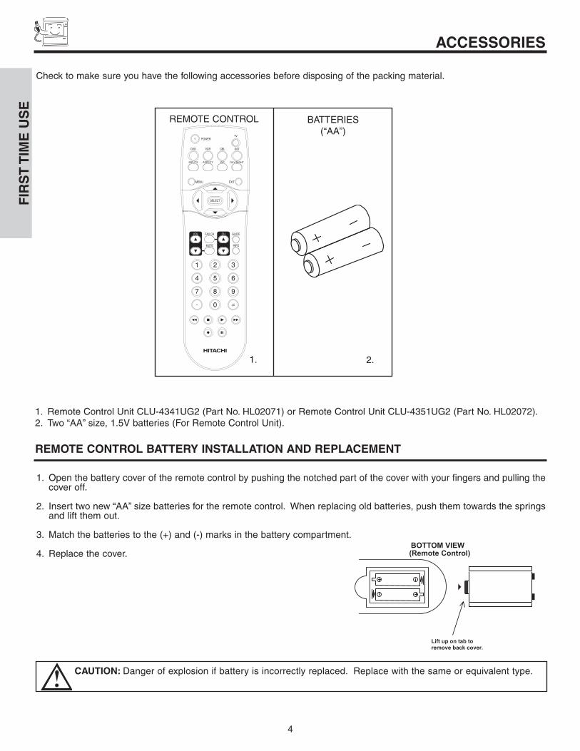
1. Remote Control Unit CLU-4341UG2 (Part No. HL02071) or Remote Control Unit CLU-4351UG2 (Part No. HL02072).2. Two “AA” size, 1.5V batteries (For Remote Control Unit).
REMOTE CONTROL BATTERY INSTALLATION AND REPLACEMENT
1. Open the battery cover of the remote control by pushing the notched part of the cover with your fingers and pulling thecover off.
2. Insert two new “AA” size batteries for the remote control. When replacing old batteries, push them towards the springsand lift them out.
3. Match the batteries to the (+) and (-) marks in the battery compartment.
4. Replace the cover.BOTTOM VIEW
Lift up on tab to remove back cover.
(Remote Control)
CAUTION: Danger of explosion if battery is incorrectly replaced. Replace with the same or equivalent type.
Check to make sure you have the following accessories before disposing of the packing material.
1. 2.
REMOTE CONTROL BATTERIES(“AA”)
FIR
ST
TIM
E U
SE

HOW TO SET UP YOUR NEW HITACHI LCD REAR PTV
5
ANTENNA
Unless your LCD Rear PTV is connected to a cable TV system or to a centralized antenna system, a good outdoor TV antenna isrecommended for best performance. However, if you are located in an exceptionally good signal area that is free from interference andmultiple image ghosts, an indoor antenna may be sufficient.
LOCATION
Select an area where sunlight or bright indoor illumination will not fall directly on the picture screen. Also, be sure that the locationselected allows a free flow of air to and from the perforated back cover of the set.
To avoid cabinet warping, cabinet color changes, and increased chance of set failure, do not place the TV where temperatures canbecome excessively hot, for example, in direct sunlight or near a heating appliance, etc.
When installing your LCD Rear PTV against a wall, keep it at least 10 cm (4 inches) from the wall.
VIEWING
The major benefit of the HITACHI LCD Rear PTV is its large viewing screen. To see this large screen at its best, test various locationsin the room to find the optimum spot for viewing.
The best picture is seen by sitting directly in front of the TV and about 10 to 18 feet from the screen. Picture brightness decreases asthe viewer moves to the left and right of the receiver.
During daylight hours, reflections from outside light may appear on the screen. If so, drapes or screens can be used to reduce thereflection or the TV can be located in a different section of the room.
If the TV’s audio output will be connected to a Hi-Fi system’s external speakers, the best audio performance will be obtained by placingthe speakers equidistant from each side of the receiver cabinet and as close as possible to the height of the picture screen center. Forbest stereo separation, place the external speakers at least four feet from the side of the TV, place the surround speakers to the side orbehind the viewing area. Differences in room sizes and acoustical environments will require some experimentation with speakerplacement for best performance.
IMPORTANT NOTES:1. Since LCD Rear PTV incorporates a high pressure lamp to display an image, it may take about one minute for the picture to
become stable, after the power has been turned on. After extended use, the picture may darken, the color may look unusual, or the lamp “goes out,” (burns out). You may hear a “pop” sound when the lamp “goes out.” These are common
characteristics of the lamp, and should not be considered defective.2. LCD Rear PTV incorporates an advanced cooling fan system to prevent from overheating. If you hear the cooling fan, it should
not be considered defective.3. If you hear a “cracking” sound from the TV cabinet, it is due to the TV’s cabinet expanding and contracting due to room
temperature changes. It has no effect on the TV’s functions.4. The LCD Rear PTV cabinet is constructed with all plastic. Make sure to place it on a flat surface. An uneven surface might
warp the cabinet and reduce the picture quality.
BEST VERTICAL VIEWING
ANGLE20
3'
0' 5' 10' 15' 20'
50
50
4" Minimum
4" Minimum
BESTHORIZONTAL
VIEWING ANGLE
5' 10' 15' 20'
S
SR
L
FIR
ST
TIM
E U
SE

HOOK-UP CABLES AND CONNECTORS
6
ANTENNA CONNECTIONS TO REAR JACK PANEL
VHF (75-Ohm) antenna/CATV (Cable TV)When using a 75-Ohm coaxial cable system, connect CATV coaxial cable to the ANTA (75-Ohm) terminal. If you have an antenna, connect the coaxial cable to the ANTB terminal.
VHF (300-Ohm) antenna/UHF antennaWhen using a 300-Ohm twin lead from an outdoor antenna, connect the VHF orUHF antenna leads to screws of the VHF or UHF adapter. Plug the adapter intothe antenna terminal on the TV.
When both VHF and UHF antennas are connectedAttach an optional antenna cable mixer to the TV antenna terminal, and connectthe cables to the antenna mixer. Consult your dealer or service store for theantenna mixer.
To outdoor antennaor CATV cable
To antenna
To outdoor VHFor UHF antenna
From UHF antenna
ANT A / ANT B From outdoorantenna orCATV System
Antenna Mixer
Most video/audio connections between components can be made with shielded video and audio cables that have phono connectors. Forbest performance, video cables should use 75-Ohm coaxial shielded wire. Cables can be purchased from most stores that sellaudio/video products. Below are illustrations and names of common connectors. Before purchasing any cables, be sure of the outputand input connector types required by the various components and the length of each cable.
300-Ohm Twin Lead ConnectorThis outdoor antenna cable must be connected to an antennaadapter (300-Ohm to 75-Ohm).
Phono ConnectorUsed on all standard video and audio cables which connect toinputs and outputs located on the television’s rear jack paneland front control panel.
“F”Type 75-Ohm Coaxial Antenna ConnectorFor connecting RF signals (antenna or cable TV) to the antennajack on the television.
S-Video (Super Video) ConnectorThis connector is used on camcorders, VCRs and laser- discplayers with an S-Video feature in place of the standard video cable to produce a high quality picture.
54321
9876
D-SUB MINI 9-Pin CableThis cable is used to connect to the RS232C input located onthe rear panel so you can control some of your TV functionsfrom an external home control system.
FIR
ST
TIM
E U
SE
HDMI CableThis cable is used to connect your external devices such as Set-Top-Boxes or DVD players equipped with an HDMI output con-nection to the TV’s HDMI input.

FRONT PANEL CONTROLS
7
�
� ���
INPUT 5
S-VIDEOEXIT
INPUT
CURSOR
SELECT
MENUVOL- VOL+ CH- CH+
� �
��� �
VIDEO
AUDIO
L/MONO R
PUSH
PUSH
� MENU/SELECT buttonThis button allows you to enter the MENU, making it possible to set TV features to your preference without using the remote. Thisbutton also serves as the SELECT button when in MENU mode.
� INPUT/EXIT buttonPress this button to display the input menu, Ant A/B, INPUT:1,2,3,4 or 5 . This button also serves as the EXIT button when in MENUmode.
� CHANNEL selectorPress these buttons until the desired channel appears in the top right corner of the TV screen. These buttons also serve asthe cursor down (�) and up (�) buttons when in MENU mode.
VOLUME levelPress these buttons for your desired sound level. The volume level will be displayed on the TV screen. These buttons also serveas the cursor left (�) and right (�) buttons when in MENU mode. When the TV power is turned OFF at a volume level 31 or greater,the volume level will default to 30 when the TV is turned ON. However, if it is set to a level 30 or less, the volume level will be at thelevel it was set when the TV is turned ON.
� FRONT INPUT JACKS (INPUT 5)Use these audio/video jacks for a quick hook-up from a camcorder or VCR to instantly view your favorite show or new recording.Press the INPUT/EXIT button on the front control panel until VIDEO: 5 appears in the top right corner of the TV screen. If you havemono sound, insert the audio cable into the left audio jack.
� IR RECEIVER sensorThe screen area acts as the IR receiver (remote sensor). When using the remote control, point it towards the screen for bestresponse.
POWER buttonPress this button to turn the TV on or off.
FIR
ST
TIM
E U
SE

FRONT PANEL CONTROLS
8
� POWER lightThis light is on during normal operation.Light Blinking Slowly (2 seconds): television lamp is cooling down. It takes 12-15 seconds to warm up and about 2 minutes to cooldown.
� TEMP indicatorThis light is off during normal operation.If this indicator is lit, the optic unit is too hot. If this indicator is blinking, the cooling fan has stopped. Please call service.
� LAMP indicator - NORMAL OPERATION INDICATOR IS OFFIf light is lit, the lamp has failed. See page 63-65 for lamp replacement procedure. Consult your Hitachi dealer for proper part.If light is blinking, lamp cover is not assembled securely after replacement.
NO LAMP LIGHTor BROKEN LAMP
WRONG LAMP UNITASSEMBLY / LAMPDOOR OPEN
Too hot inside theOPTIC unit
COOLING FAN STOPPED
NORMALOPERATION
COOL DOWN
COOL DOWN 3. 15~20 secs. Lamp is off. Power ON is available.
LIGHT ON
BLINKING
LIGHT ON
BLINKING
LIGHT ON
FAST BLINKING
SLOW BLINKING
INDICATOR INDICATION MEANING ACTION
LAMP LED
TEMPLED
POWER
Need to replace ifLAMP still does not light by“Power On” again.Check assembly condition ofLAMP UNIT
Call for Service
NOTES:
1.
2. If the LAMP, TEMP, and POWER LED are blinking in the order below, the television is warming up.
3. Your Hitachi LCD Rear Projection Television may appear to be OFF when it is set to input 1 ~ input 5 and the video signal is not received from the input jacks. Please make sure the Blue Power light indicator is not lit (OFF) whenyou are not watching for long lasting performance.
4. Your Hitachi LCD Rear Projection Television has an internal lamp that lights up the TV screen. Make sure to turn offthe Power when you do not watch the LCD Rear Projection Television for longer lamp life.
POWER TEMP LAMP
1. ~5 secs. Lamp is still on. Power ON is available.
2. 5~15 secs. Lamp is off. Power ON is not available.
IMPORTANT NOTES:A small number of missing, discolored, or lit all the time dots or pixels is characteristic of TFT LCD technology due to the manufacturing process irrespective of manufacturer.
FIR
ST
TIM
E U
SE
9
FRONT PANEL JACKS AND CONNECTORS
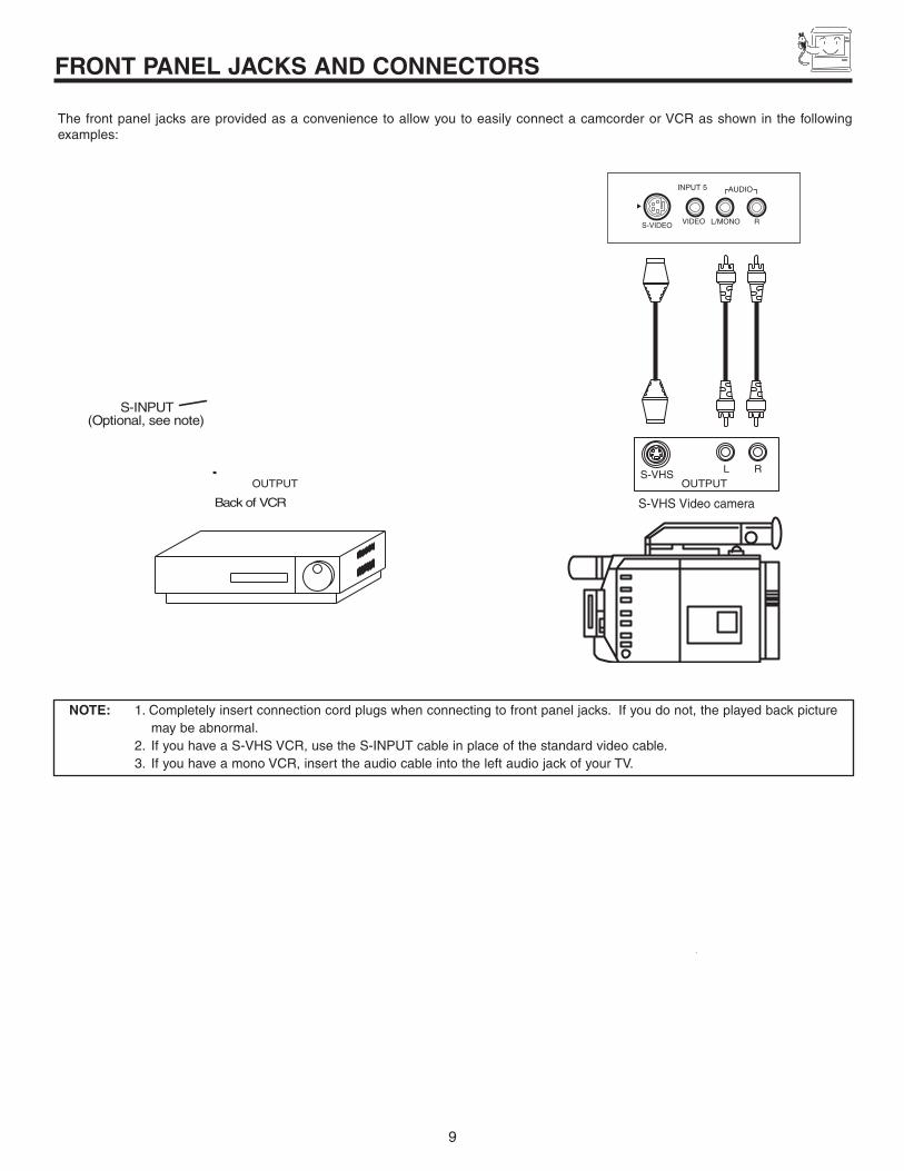
The front panel jacks are provided as a convenience to allow you to easily connect a camcorder or VCR as shown in the followingexamples:
NOTE: 1. Completely insert connection cord plugs when connecting to front panel jacks. If you do not, the played back picture may be abnormal.
2. If you have a S-VHS VCR, use the S-INPUT cable in place of the standard video cable.3. If you have a mono VCR, insert the audio cable into the left audio jack of your TV.
INPUT 5
S-VIDEO VIDEO
AUDIO
L/MONO R
INPUT 5S-VIDEOVIDEOAUDIOL / M O N O
R
FIRST TIME USE

10
REAR PANEL JACKS
� Antenna Input/OutputThe remote control allows you to switch between two separate 75-Ohm RF antenna inputs, ANT A and ANT B. ANT A input canbe displayed as a main picture or sub-picture. ANT B can only be displayed as a main picture. (ANT B cannot be displayed as asub-picture.) The antenna output labeled “TO CONVERTER” allows the ANT A connection to pass directly to a different sourcesuch as a cable box, only when ANT B is displayed as a main picture.
� Audio/Video Inputs 1, 2, 3 and 4By using the INPUTS button and CURSOR buttons of the remote control you can select each video source. Use the audio and videoinputs to connect external devices, such as VCRs, camcorders, laserdisc players, DVD players etc. (If you have mono sound, insertthe audio cable into the left audio jack.)
� MONITOR OUTThese jacks provide fixed or variable audio and video signals which are used for recording. Use the S-VIDEO Output for highquality video output (see page 65).
S-VIDEO Inputs 3 and 4Inputs 3 and 4 provide S-VIDEO (Super Video) jacks for connecting equipment with S-VIDEO output capability.
� Component: Y-PBPR InputsInputs 1 and 2 provide Y-PBPR jacks for connecting equipment with this capability, such as a DVD player or Set Top Box. You mayuse composite video signal for both inputs.
NOTE: You may use VIDEO or S-VIDEO inputs to connect to INPUT 3 and 4, but only one of these inputs may be used at atime.
�
�
�
�
�
TOCONVERTER
1 2 3 4 5
9876
�
ANT B
ANT A
S-VIDEO
R
L
VIDEO
AUDIO
(MONO) (MONO) (MONO) (MONO)
PR
PB
Y/VIDEO
Y/VIDEO
PR
PB
MONITOR OUT INPUT 4 INPUT 3
INPUT 2 INPUT 1
HDMI 1
RS232C
AUDIOTO HI-FI
TV AS CENTER
NOTES: 1. Do not connect composite VIDEO and S-VIDEO to Input 3, 4 or 5 at the same time. S-VIDEO has priority over VIDEO input.
2. Your component outputs may be labeled Y, B-Y, and R-Y. In this case, connect the components B-Y output to the TV’s PB input and the components R-Y output to the TV’s PR input.
3. Your component outputs may be labeled Y-CBCR. In this case, connect the component CB output to the TV’s PB input and the component CR output to the TV’s PR input.
4. It may be necessary to adjust TINT to obtain optimum picture quality when using the Y-PBPR inputs (see page 38).
5. To ensure no copyright infringement, the MONITOR OUT output will be abnormal, when using the Y-PBPR jacks.
6. Input 1 and Input 2 (Y/VIDEO) can be used for composite video and component video input.
FIR
ST
TIM
E U
SE

11
REAR PANEL JACKS
� HDMI1 (High Definition Multimedia Interface) (INPUT 1)About HDMIHDMI is the next-generation all digital interface for consumer electronics. HDMI enables the secure distribution of uncompressedhigh-definition video and multi-channel audio in a single cable. Because digital television (DTV) signals remain in digital format,HDMI assures that pristine high-definition images retain the highest video quality from the source all the way to your televisionscreen.
Use the HDMI input for your external devices such as Set-Top-Boxes or DVD players equipped with an HDMI output connection.
HDMI, the HDMI logo and High-Definition Multimedia Interface are trademarks or registered trademarks of HDMI Licensing LLC.
RS232C InputFor use with third party home Audio/Video control systems which are commercially available. Please see your dealer regardingthese “non Hitachi” home control systems (see page 61 to activate this input).
� TV AS CENTER (INPUTS 1-4)These jacks are for stereo amplifiers with center signal output capability. This feature allows the TV speakers to be used as a centerspeaker. The TV must be set as a center channel by selecting “TV as Center” on the Internal Speakers Settings of the Audio Menu(see page 42).
NOTES: 1. The HDMI input is not intended for use with personal computers.
2. Only DTV formats such as 1080i, 720p, 480i and 480p are available for HDMI input.
FIRST TIME USE

12
REAR PANEL CONNECTIONS
NOTES: 1. Connect only 1 component to each input jack.2. Follow connections that pertain to your personal entertainment system.3. Inputs 1 and 2 can accomodate Composite and Component video signals.4. Cables are not included with the purchase of this TV, except when noted as “provided”.
TOCONVERTER
1 2 3 4 5
9876
ANT B
ANT A
S-VIDEO
R
L
VIDEO
AUDIO
(MONO) (MONO) (MONO) (MONO)
PR
PB
Y/VIDEO
Y/VIDEO
PR
PB
MONITOR OUT INPUT 4 INPUT 3
INPUT 2 INPUT 1
HDMI 1
RS232C
AUDIOTO HI-FI
TV AS CENTER
VCR #2
Outside antenna ordigital cable
Laserdisc player, VCR,camcorder, etc.
VCR #1
DVD PlayerOUTPUT
Y PB/CB PR/CR L R
External DigitalComponent with
HDMI outputcapability
INPUT
S-VIDEO V L ROUTPUT
S-VIDEO V L ROUTPUT
S-VIDEO

13
TIPS ON REAR PANEL CONNECTIONS
• S-VIDEO, HDMI and component connections are provided for high performance laserdisc players, VCRs etc. that have this feature. Use these connections in place of the standard video connection if your device has this feature.
• If your device has only one audio output (mono sound), connect it to the left audio jack on the television.
• Refer to the operating guide of your other electronic equipment for additional information on connecting your hook-up cables.
• A single VCR can be used for VCR #1 and VCR #2, but note that a VCR cannot record its own video or line output (INPUT: 3 inthe example on page 12). Refer to your VCR operating guide for more information on line input-output connections.
• You may use VIDEO or S-VIDEO inputs to connect to Input 3, Input 4 or Input 5, but only one of these may be used at a time.
• Connect only 1 component (VCR, DVD player, camcorder, etc.) to each input jack.
• COMPONENT: Y-PBPR (Input 1 & 2) connections are provided for high performance components, such as DVD players and set-top-boxes. Use these connections in place of the standard video connection if your device has this feature. Input 1 and 2accepts both composite and component video signals.
• Your component outputs may be labeled Y, B-Y, and R-Y. In this case, connect the components B-Y output to the TV’s PB inputand the components R-Y output to the TV’s PR input.
• Your component outputs may be labeled Y-CBCR. In this case, connect the components CB output to the TV’s PB input and the components CR output to the TV’s PR input.
• You may use composite video signal for Input 1~Input 5.
• It may be necessary to adjust TINT to obtain optimum picture quality when using the Y-PBPR inputs. (See page 38)
• To ensure no copyright infringement, the MONITOR OUT output may be abnormal, when using the Y-PBPR jacks.
• When using HDMI or DVI input from a Set-Top-Box, it is recommended to use a 1080i or 720p input signal.
FIR
ST
TIM
E U
SE

14
CONNECTING EXTERNAL AUDIO DEVICES
CENTEROUT
Stereo System Amplifieror DVD Player
TOCONVERTER
1 2 3 4 5
9876
ANT B
ANT A
S-VIDEO
R
L
VIDEO
AUDIO
(MONO) (MONO) (MONO) (MONO)
PR
PB
Y/VIDEO
Y/VIDEO
PR
PB
MONITOR OUT INPUT 4 INPUT 3
INPUT 2 INPUT 1
HDMI 1
RS232C
AUDIOTO HI-FI
TV AS CENTER
REAR PANEL OF TELEVISION
NOTE: 1. See page 42 for AUDIO-Internal Speakers.
Match the numbers below to the diagram for speaker placement.
� The television’s internal speakers will act as center speaker (select Audio-Internal Speakers-TV as Center see page 42).
� These FRONT left and right speakers are connected to the FRONT output of a separate audio amplifier.
� These REAR left and right speakers are connected to the REAR output of a separate audio amplifier.
� This subwoofer is connected to the LFE/Sub Out output of a separate audio amplifier.
FIRST TIME USE


16
CONNECTING EXTERNAL VIDEO DEVICES
CONNECTING A STEREO SOURCE TO INPUT1~INPUT51. Connect the cable from the VIDEO OUT of the VCR or the laserdisc player to the INPUT (VIDEO) jack, as shown on the TV set
below.
2. Connect the cable from the AUDIO OUT R of the VCR or the laserdisc player to the INPUT (AUDIO/R) jack.
3. Connect the cable from the AUDIO OUT L of the VCR or the laserdisc player to the INPUT (AUDIO/L) jack.
4. Press the INPUTS button, then select INPUT 3 from the INPUTS menu to view the program from the VCR or laserdisc player.The VIDEO OSD label disappears automatically after approximately four seconds.
5. Select Antenna from the INPUTS menu to return to the previous channel.
NOTES: 1. Completely insert the connection cord plugs when connecting to rear panel jacks. The picture and sound that is played back will be abnormal if the connection is loose.
2. A single VCR can be used for VCR #1 and VCR #2 (see page 12), but note that a VCR cannot record its own video or line output. Refer to your VCR operating guide for more information on line input-output connections.
1 2 3 4 5
9876
RS232C
TOCONVERTER
ANT A
ANT B
S-VIDEO
R
L
VIDEO
AUDIO
(MONO) (MONO) (MONO) (MONO)
PR
PB
Y/VIDEO
Y/VIDEO
PR
PB
MONITOR OUT INPUT 4 INPUT 3
INPUT 2 INPUT 1
HDMI 1
VCR
OUTPUT
R L V
AUDIOTO HI-FI
TV AS CENTER
FIR
ST
TIM
E U
SE

17
CONNECTING EXTERNAL VIDEO DEVICES
CONNECTING AN S-VIDEO SOURCE TO INPUT 3, 4 AND 51. Connect the cable from the S-VIDEO OUT of the VCR or the laserdisc player to the INPUT (S-VIDEO) jack, as shown on the TV
set below.
2. Connect the cable from the AUDIO OUT R of the VCR or the laserdisc player to the INPUT (AUDIO/R) jack.
3. Connect the cable from the AUDIO OUT L of the VCR or the laserdisc player to the INPUT (AUDIO/L) jack.
4. Press the INPUTS button, then select INPUT 3 from the INPUTS menu to view the program from the VCR or laserdisc player.The VIDEO OSD label disappears automatically after approximately four seconds.
5. Select Antenna from the INPUTS menu to return to the previous channel.
NOTES: 1. Completely insert the connection cord plugs when connecting to rear panel jacks. The picture and sound that is played back will be abnormal if the connection is loose.
2. A single VCR can be used for VCR #1 and VCR #2 (see page 12), but note that a VCR cannot record its own video or line output. Refer to your VCR operating guide for more information on line input-output connections.
1 2 3 4 5
9876
RS232C
TOCONVERTER
ANT A
ANT B
S-VIDEO
R
L
VIDEO
AUDIO
(MONO) (MONO) (MONO) (MONO)
PR
PB
Y/VIDEO
Y/VIDEO
PR
PB
MONITOR OUT INPUT 4 INPUT 3
INPUT 2 INPUT 1
HDMI 1
VCR
R L VS-VIDEO
AUDIOTO HI-FI
TV AS CENTER
FIR
ST
TIM
E U
SE
18
CONNECTING EXTERNAL VIDEO DEVICES
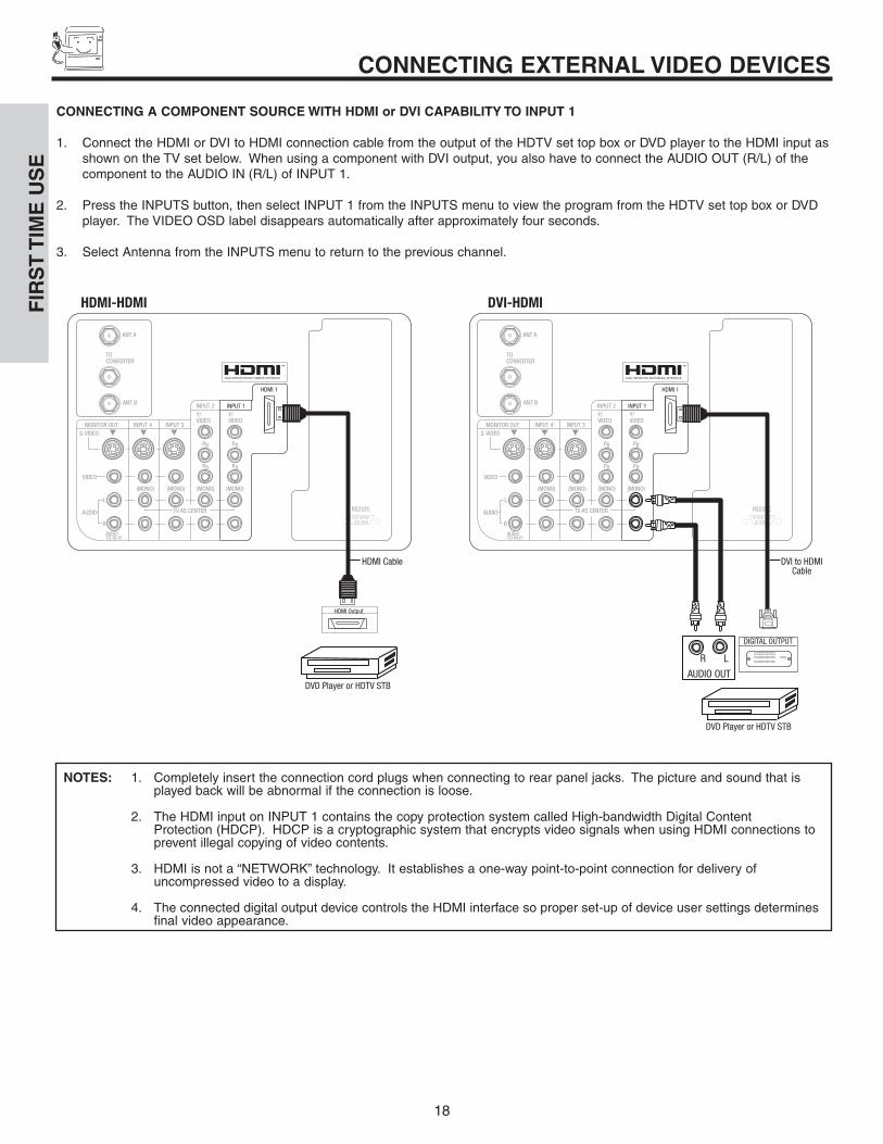
CONNECTING A COMPONENT SOURCE WITH HDMI or DVI CAPABILITY TO INPUT 1
1. Connect the HDMI or DVI to HDMI connection cable from the output of the HDTV set top box or DVD player to the HDMI input as shown on the TV set below. When using a component with DVI output, you also have to connect the AUDIO OUT (R/L) of the component to the AUDIO IN (R/L) of INPUT 1.
2. Press the INPUTS button, then select INPUT 1 from the INPUTS menu to view the program from the HDTV set top box or DVD player. The VIDEO OSD label disappears automatically after approximately four seconds.
3. Select Antenna from the INPUTS menu to return to the previous channel.
TOCONVERTER
ANT A
ANT B
1 2 3 4 5
9876
RS232C1 2 3 4 5
9876
RS232C
DVD Player or HDTV STB
R L
AUDIO OUT
DIGITAL OUTPUT
TOCONVERTER
ANT A
ANT B
S-VIDEO
R
L
VIDEO
AUDIO
(MONO) (MONO) (MONO) (MONO)
PR
PB
Y/VIDEO
Y/VIDEO
PR
PB
MONITOR OUT INPUT 4 INPUT 3
INPUT 2 INPUT 1
HDMI 1
HDMI Output
DVD Player or HDTV STB
HDMI Cable
AUDIOTO HI-FI
TV AS CENTER
HDMI-HDMI
S-VIDEO
R
L
VIDEO
AUDIO
(MONO) (MONO) (MONO) (MONO)
PR
PB
Y/VIDEO
Y/VIDEO
PR
PB
MONITOR OUT INPUT 4 INPUT 3
INPUT 2 INPUT 1
HDMI 1
DVI to HDMICable
AUDIOTO HI-FI
TV AS CENTER
DVI-HDMI
NOTES: 1. Completely insert the connection cord plugs when connecting to rear panel jacks. The picture and sound that is played back will be abnormal if the connection is loose.
2. The HDMI input on INPUT 1 contains the copy protection system called High-bandwidth Digital Content Protection (HDCP). HDCP is a cryptographic system that encrypts video signals when using HDMI connections to prevent illegal copying of video contents.
3. HDMI is not a “NETWORK” technology. It establishes a one-way point-to-point connection for delivery of uncompressed video to a display.
4. The connected digital output device controls the HDMI interface so proper set-up of device user settings determinesfinal video appearance.
FIR
ST
TIM
E U
SE
19
CONNECTING EXTERNAL VIDEO DEVICES
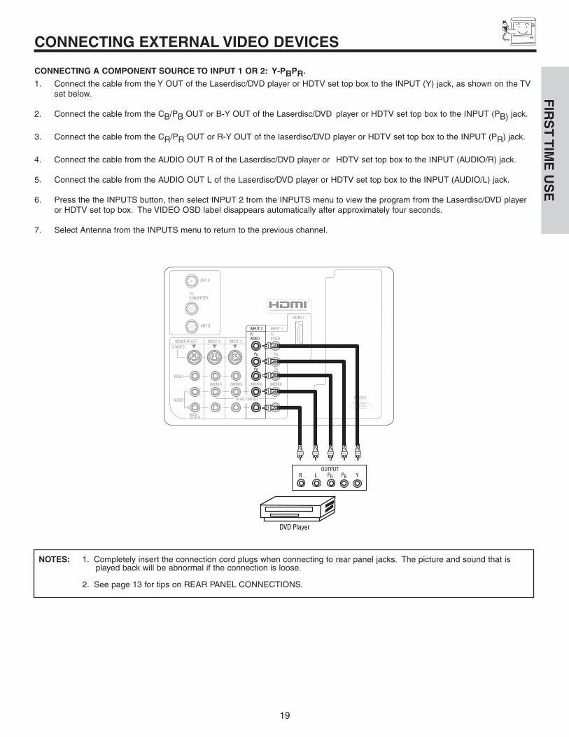
CONNECTING A COMPONENT SOURCE TO INPUT 1 OR 2: Y-PBPR.
1. Connect the cable from the Y OUT of the Laserdisc/DVD player or HDTV set top box to the INPUT (Y) jack, as shown on the TV set below.
2. Connect the cable from the CB/PB OUT or B-Y OUT of the Laserdisc/DVD player or HDTV set top box to the INPUT (PB) jack.
3. Connect the cable from the CR/PR OUT or R-Y OUT of the laserdisc/DVD player or HDTV set top box to the INPUT (PR) jack.
4. Connect the cable from the AUDIO OUT R of the Laserdisc/DVD player or HDTV set top box to the INPUT (AUDIO/R) jack.
5. Connect the cable from the AUDIO OUT L of the Laserdisc/DVD player or HDTV set top box to the INPUT (AUDIO/L) jack.
6. Press the the INPUTS button, then select INPUT 2 from the INPUTS menu to view the program from the Laserdisc/DVD player or HDTV set top box. The VIDEO OSD label disappears automatically after approximately four seconds.
7. Select Antenna from the INPUTS menu to return to the previous channel.
NOTES: 1. Completely insert the connection cord plugs when connecting to rear panel jacks. The picture and sound that is played back will be abnormal if the connection is loose.
2. See page 13 for tips on REAR PANEL CONNECTIONS.
DVD Player
1 2 3 4 5
9876
RS232C
TOCONVERTER
ANT A
ANT B
S-VIDEO
R
L
VIDEO
AUDIO
(MONO) (MONO) (MONO) (MONO)
PR
PB
Y/VIDEO
Y/VIDEO
PR
PB
MONITOR OUT INPUT 4 INPUT 3
INPUT 2 INPUT 1
HDMI 1
OUTPUTPR PB Y R L
AUDIOTO HI-FI
TV AS CENTER
FIR
ST
TIM
E U
SE
20
THE REMOTE CONTROLT
HE
RE
MO
TE
CO
NT
RO
L
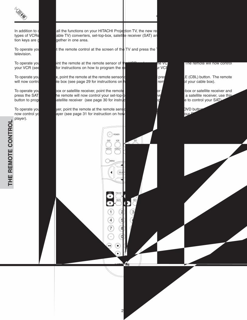
In addition to controlling all the functions on your HITACHI Projection TV, the new remote control is designed to operate differenttypes of VCRs, CATV (Cable TV) converters, set-top-box, satellite receiver (SAT) and DVD players with one touch. Basic opera-tion keys are grouped together in one area.
To operate your TV, point the remote control at the screen of the TV and press the TV button. The remote will now control yourtelevision.
To operate your VCR, point the remote at the remote sensor of the VCR and press the VCR button. The remote will now controlyour VCR (see page 32 for instructions on how to program the remote to control your VCR).
To operate your cable box, point the remote at the remote sensor of the cable box and press the CABLE (CBL) button. The remotewill now control your cable box (see page 29 for instructions on how to program the remote to control your cable box).
To operate your set-top-box or satellite receiver, point the remote at the remote sensor of the set-top-box or satellite receiver andpress the SAT button. The remote will now control your set-top-box or satellite receiver. If you have a satellite receiver, use thisbutton to program your satellite receiver (see page 30 for instructions on how to program the remote to control your SAT).
To operate your DVD player, point the remote at the remote sensor of the DVD player and press the DVD button. The remote willnow control your DVD player (see page 31 for instruction on how to program the remote to control your DVD player).
21
HOW TO USE THE REMOTE TOCONTROL YOUR LCD REAR PTV
TH
E R
EM
OT
E C
ON
TR
OL
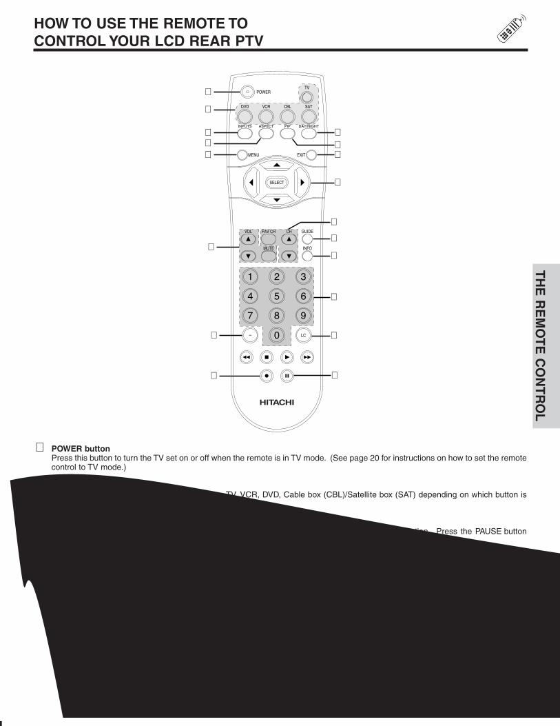
� POWER buttonPress this button to turn the TV set on or off when the remote is in TV mode. (See page 20 for instructions on how to set the remotecontrol to TV mode.)
� MODE buttonsThese buttons allow the remote to control your TV, VCR, DVD, Cable box (CBL)/Satellite box (SAT) depending on which button ispressed.
� PAUSE buttonPress the PAUSE button to freeze the picture. Press the EXIT button to return the picture to motion. Press the PAUSE buttonrepeatedly to cycle through the three different freeze modes (see page 28).
�
�
�
��
�
�
�
�
�
�
�
�
�
�
Freeze Freeze
Freeze
Freeze
Freeze
e

22
HOW TO USE THE REMOTE TOCONTROL YOUR LCD REAR PTV
� ASPECT buttonPress this button to quickly change the picture format ASPECT ratio.
Depending on the input signal format received, the picture format ratio allows you to adjust the images through the following options.
4:3 STANDARD Use this aspect mode to display conventional (4:3) images. Side panels (gray areas) are placed to theleft and right of the image to preserve the original aspect ratio of the source.
4:3 EXPANDED Use this aspect mode to display conventional (4:3) sources by linearly increasing image expansion fromthe center towards the edges of the display area in order to fill it.
4:3 Zoom1/Zoom2 Use these aspect modes to zoom in on conventional (4:3) sources.
16:9 STANDARD Use this aspect mode to display 16:9 sources like HDTV and DVD’s preserving the original 16:9 aspectratio.
16:9 Zoom Use this aspect to Zoom-in once while in 16:9 aspect.
(1) Antenna Analog Channels
(2) 480P Input
(3) HDMI/720P/1080i Input
4:3
INPUT 4:3 EXPANDED 4:3 ZOOM1
4:3 ZOOM216:9 STANDARD
4:3 STANDARD
INPUT 4:3 EXPANDED 4:3 ZOOM1
4:3 ZOOM216:9 STANDARD
4:3 STANDARD
INPUT
16:9
16:9 STANDARD 16:9 ZOOM
16:9 ZOOM
16:9 ZOOM
16:9
4:3 EXPANDED
NOTES: 1. The Aspect Style setting you select for an ANT input will automatically be set for the other ANT inputs. However, allfive video inputs have independent Aspect Style settings.
2. Vertical position adjustments are directly available when you choose 4:3 EXPANDED/ZOOM1/ZOOM2 or 16:9ZOOM aspect style (see also page 43).
TH
E R
EM
OT
E C
ON
TR
OL


24
HOW TO USE THE REMOTE TOCONTROL YOUR LCD REAR PTVT
HE
RE
MO
TE
CO
NT
RO
L
PICTURE-IN-PICTURE buttonSee separate section on pages 26-28 for a description.
� MENU buttonThe MENU button will start the On-Screen Display.
� GUIDE button [Cable Box (CBL), Satellite Receiver (SAT)/Set-Top-Box (STB) mode only]The use of this button is only applicable when the remote control is in (CBL) and (SAT/STB) mode. Press this button to access theChannel Guide of the (CBL), and (SAT/STB).
� EXIT buttonThis button will exit all On-Screen Displays.
� CURSOR buttons/SELECT buttonAll the On-Screen Display features can be set or adjusted by using the CURSOR buttons and the SELECT button, except fornumeric entries. Press the CURSOR buttons toward desired direction and press the SELECT button to select.
INFO buttonPress this button when you want to check the channel being received, the picture source, if the channel has stereo (ST) or secondaudio program (SAP), the time, CHANNEL ID and if the TIMER is set.
Main Picture SourceTime
AspectMode
Day/NightMode
ClosedCaptioning
Event Timer
3:32 PMAnt A 22ST Stereo
R
Day Off HD 1080i 4:3 Expanded --:-- AM --:-- PMView
CC
Audio BroadcastBroadcast Rating
INFO
When an S-VIDEOInput is connected toVIDEO: 3.
When a COMPONENTVIDEO: Y-PBPR Input isconnected to VIDEO: 1.
3:32 PMS-IN: 3
VID 3
3:32 PMYPBPR: 1
VID 1
INFO
INFO
NOTES: 1. The Sleep Timer info will show momentarily after releasing INFO button.2. Press the INFO button again or the EXIT button to return to normal viewing.
25
HOW TO USE THE REMOTE TOCONTROL YOUR LCD REAR PTV
TH
E R
EM
OT
E C
ON
TR
OL
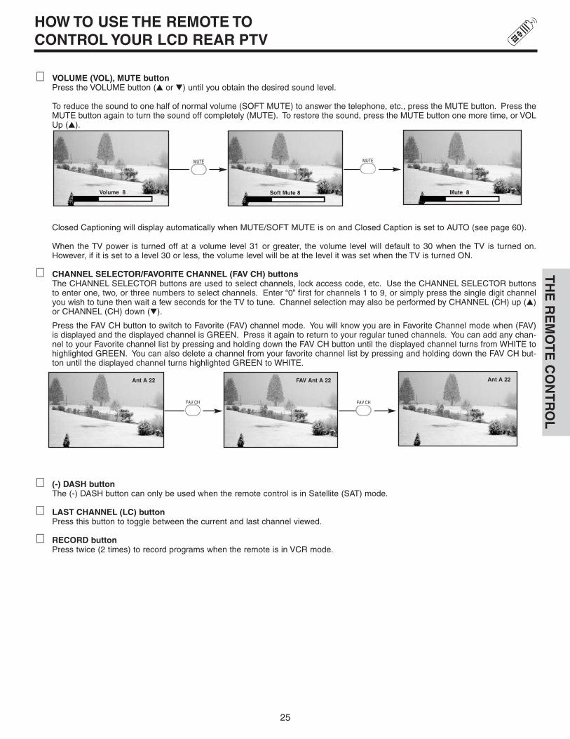
� VOLUME (VOL), MUTE buttonPress the VOLUME button (� or �) until you obtain the desired sound level.
To reduce the sound to one half of normal volume (SOFT MUTE) to answer the telephone, etc., press the MUTE button. Press theMUTE button again to turn the sound off completely (MUTE). To restore the sound, press the MUTE button one more time, or VOLUp (�).
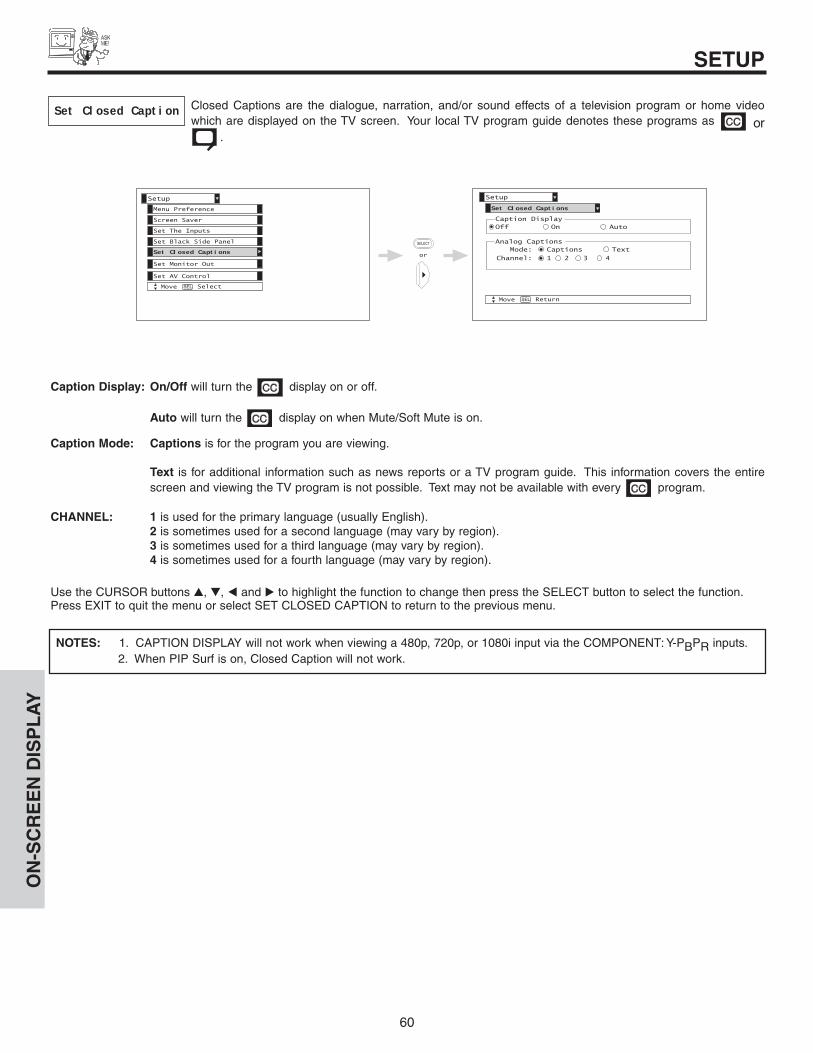
Closed Captioning will display automatically when MUTE/SOFT MUTE is on and Closed Caption is set to AUTO (see page 60).
When the TV power is turned off at a volume level 31 or greater, the volume level will default to 30 when the TV is turned on.However, if it is set to a level 30 or less, the volume level will be at the level it was set when the TV is turned ON.
� CHANNEL SELECTOR/FAVORITE CHANNEL (FAV CH) buttonsThe CHANNEL SELECTOR buttons are used to select channels, lock access code, etc. Use the CHANNEL SELECTOR buttonsto enter one, two, or three numbers to select channels. Enter “0” first for channels 1 to 9, or simply press the single digit channelyou wish to tune then wait a few seconds for the TV to tune. Channel selection may also be performed by CHANNEL (CH) up (�)or CHANNEL (CH) down (�).
Press the FAV CH button to switch to Favorite (FAV) channel mode. You will know you are in Favorite Channel mode when (FAV)is displayed and the displayed channel is GREEN. Press it again to return to your regular tuned channels. You can add any chan-nel to your Favorite channel list by pressing and holding down the FAV CH button until the displayed channel turns from WHITE tohighlighted GREEN. You can also delete a channel from your favorite channel list by pressing and holding down the FAV CH but-ton until the displayed channel turns highlighted GREEN to WHITE.
� (-) DASH buttonThe (-) DASH button can only be used when the remote control is in Satellite (SAT) mode.
� LAST CHANNEL (LC) buttonPress this button to toggle between the current and last channel viewed.
� RECORD buttonPress twice (2 times) to record programs when the remote is in VCR mode.
Volume 8 Mute 8Soft Mute 8
Ant A 22 FAV Ant A 22 Ant A 22

26
Use above connection to view VCR program as a sub-picture while viewing another program as main picture (ANT A, ANT B,INPUT:2, INPUT:3, INPUT:4, or INPUT:5). You may also view the VCR program as a main picture while viewing another programas a sub-picture (ANT A, INPUT:2, INPUT:3, INPUT:4 or INPUT:5).
� PIP buttonPress the PIP button and a sub-picture will appear in one of the four different modes (POP, PIP, SPLIT or SURF), depending on theINPUT signal. To change the PIP mode, use the PIP button to cycle through the four different modes. Press the EXIT button toreturn to normal viewing from any PIP mode.
POP MODE PICTURE-IN-PICTUREPOP Mode PIP displays the sub-picture outside of the main picture. Use the CURSOR button � or � to move the sub-picture. Thisfeature is not available with a 1080i component input or Digital signal 16x9 Format. Please refer to the PICTURE-IN-PICTUREMODES Table (see page 28).
NOTES: 1. PIP MODE Picture-in-Picture is only available with a 1080i component or digital signal 4x3 Format.2. Use the CURSOR button � or � to enable the sub-picture sound.
Main Picture
Sub Picture
Your HITACHI LCD Rear PTV incorporates Two Tuner technology designed for improved viewing enjoyment.This Two Tuner feature allowsyou to view antenna inputs on both the main picture and sub-picture simultaneously, with separate tuning control for each.
ANT A input can be viewed as both the main picture and the sub-picture simultaneously. ANT B can only be viewed as a main picture.To select between main picture and PIP sub-picture tuning, use the CURSOR buttons on the remote. The green highlighted channeldisplay will move with every press of the CURSOR button � or �.
The Picture-in-Picture feature is convenient when you want to watch more than one program at the same time. You can watch a TVprogram while viewing other programs from any of the video inputs.
PICTURE-IN-PICTURE (PIP)T
HE
RE
MO
TE
CO
NT
RO
L
�
�
OUTPUTAudio Video
VCR
1 2 3 4 5
9876
RS232C
ANT A
S-VIDEO
R
L
VIDEO
AUDIO
(MONO) (MONO) (MONO) (MONO)
PR
PB
Y/VIDEO
Y/VIDEO
PR
PB
MONITOR OUT INPUT 4 INPUT 3
INPUT 2 INPUT 1
HDMI 1
ANT B
AUDIOTO HI-FI
ToConverter
27
PICTURE-IN-PICTURE (PIP)T
HE
RE
MO
TE
CO
NT
RO
L
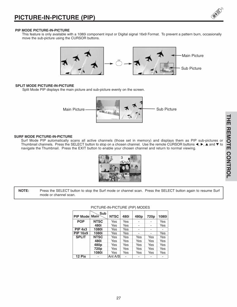
SPLIT MODE PICTURE-IN-PICTURESplit Mode PIP displays the main picture and sub-picture evenly on the screen.
Main Picture Sub Picture
SURF MODE PICTURE-IN-PICTURESurf Mode PIP automatically scans all active channels (those set in memory) and displays them as PIP sub-pictures orThumbnail channels. Press the SELECT button to stop on a chosen channel. Use the remote CURSOR buttons �, �, � and � tonavigate the Thumbnail. Press the EXIT button to enable your chosen channel and return to normal viewing.
PICTURE-IN-PICTURE (PIP) MODES
NTSC Yes Yes - - Yes480i Yes Yes - - Yes
1080i Yes Yes - - -1080i Yes Yes - - YesNTSC Yes Yes Yes Yes Yes480i Yes Yes Yes Yes Yes480p Yes Yes Yes Yes Yes720p Yes Yes Yes Yes Yes1080i Yes Yes Yes Yes Yes
- Ant A/B - - - -
NTSC 480i 480p 720p 1080iPIP ModePOP
PIP 4x3PIP 16x9
SPLIT
12 Pix
MainSub
1 2 3 4
5 6 7 8
9 10 11 12
PIP MODE PICTURE-IN-PICTUREThis feature is only available with a 1080i component input or Digital signal 16x9 Format. To prevent a pattern burn, occasionallymove the sub-picture using the CURSOR buttons.
NOTE: Press the SELECT button to stop the Surf mode or channel scan. Press the SELECT button again to resume Surfmode or channel scan.
Main Picture
Sub Picture

28
� PAUSE buttonIf you wish to freeze the sub-picture, press the PAUSE button. This is convenient when trying to write down the address for amail order company, recording statistics for a sporting event, etc. To return the picture to motion, press the EXIT button. Pressthe PAUSE button repeatedly to toggle between FREEZE modes (Main Freeze, SPLIT and STROBE).
MAIN FREEZEPress the PAUSE button to freeze one frame of the picture you are currently viewing and the frozen frame will show in the MainPicture. Press the EXIT button to return to normal viewing. This feature is useful for freezing a picture frame with addresses.
NOTES: 1. The default FREEZE mode is the MAIN freeze followed by the SPLIT freeze and then the STROBE freeze. The last Freeze mode you selected before you pressed the EXIT button will be the one that comes up after pressing the PAUSE button again.
2. Each freeze frame is delayed about 0.1 (1/10) second.3. Strobe Freeze is not available in 480p/720p/1080i inputs.
STROBE FREEZEPress the PAUSE button to freeze three frames of the picture you are currently viewing (only the 3 sub-pictures will freeze). Pressthe EXIT button to return to normal viewing. This feature is useful for viewing a moving picture that has many details, for example,a close play in a sporting event or a golf swing.
FREEZE FREEZE
SPLIT FREEZEPress the PAUSE button to freeze the picture you are currently viewing (only the right sub-picture will freeze). Press the EXIT buttonto return to normal viewing.
Main Picture Sub Picture
Hot Springs Clay MaskC/O John Doe
Run-Spa RetreatP.O. Box 55512
Any Town, USA 98765Check or
Money Order Only1-800-555-1212
Freeze Freeze
Freeze
Freeze
Freeze
PICTURE-IN-PICTURE (PIP)T
HE
RE
MO
TE
CO
NT
RO
L

29
USING THE REMOTE TO CONTROL CABLE BOX FUNCTIONST
HE
RE
MO
TE
CO
NT
RO
L
Operating the precoded function for your cable box.
This remote is designed to operate different types of cable boxes.You must first program the remote to match the remote system of yourcable box (refer to page 33 for pre-codes).
1. Turn ON your cable box.
2. Aim the remote control at the front of your cable box.
3. To switch to Cable (CBL) pre-coded mode, press and release the CABLE (CBL) button.
4. Hold down the CBL button on the remote and enter the two digit preset code that matches your cable box as shown on page 33.Release the CBL button.
5. Aim the remote at the cable box and press the POWER button. The remote will turn off your cable box when the correct two digitpreset code is entered. When this occurs, the remote control is programmed for your cable box. If the cable box does not turn off,try a different two digit preset code.
6. The remote will now control your Cable box.
NOTES:1. If your cable box cannot be operated after performing the
above procedures, your cable box code has not beenprecoded into the remote.
2. In the unlikely event that your cable box cannot beoperated after performing the above procedures, pleaseconsult your cable box operating guide.
3. The remote control will remember the codes you haveprogrammed until the batteries are removed from theremote control. After replacing the batteries repeat theentire programming procedure as stated above.
� CABLE (CBL) buttonThis button allows the remote to control your cable box bysetting it to CABLE mode.
� PRECODED CABLE BOX buttonsThese buttons transmit the chosen precoded cable codes.
� EXCLUSIVE TV buttonsThese buttons are for operating the TV.
�
�
�
�
�
�
MY CABLE BOX CODE IS:
NOTE: Refer to instruction manual of the Cable Box for operation of the buttons exclusively for the Cable Box.

30
USING THE REMOTE TO CONTROL SET-TOP-BOX/SATELLITE RECEIVER FUNCTIONS
TH
E R
EM
OT
E C
ON
TR
OL
Operating the precoded function for your set-top-box/satellite receiver.
This remote is designed to operate different types of set-top-box/satellite systems. You must first program the remote to match theremote system of your set-top-box/satellite systems (refer to page 33 for pre-codes).
1. Turn ON your set-top-box/satellite systems.
2. Aim the remote control at the front of your set-top-box/satellite systems.
3. To switch to set-top-box/satellite (STB) pre-coded mode, press and release the SAT button.
4. Hold down the SAT button on the remote and enter the two digit preset code that matches your set-top-box/satellite receiver asshown on page 33. Release the SAT button.
5. Aim the remote at the set-top-box/satellite receiver and press the POWER button. The remote will turn off your set-top-box/satel-lite receiver when the correct two digit preset code is entered. When this occurs, the remote control is programmed for your set-top-box/satellite receiver. If the set-top-box/satellite receiver does not turn off, try a different two digit preset code.
6. The remote will now control your set-top-box/satellite receiver.
NOTES:1. If your set-top-box/satellite receiver cannot be operated
after performing the above procedures, your set-top-box/satellite receiver code has not been precoded into theremote.
2. In the unlikely event that your set-top-box/satellitereceiver cannot be operated after performing the aboveprocedures, please consult your set-top-box/satellitereceiver operating guide.
3. The remote control will remember the codes you haveprogrammed until the batteries are removed from theremote control. After replacing the batteries repeat theentire programming procedure as stated above.
� SAT (Set-Top-Box/Satellite) buttonThis button allows the remote to control your set-top-box/satellite receiver by setting it to SET-TOP-BOX/SATEL-LITE mode.
� PRE-CODED SET-TOP-BOX/SATELLITE RECEIVER buttonsThese buttons transmit the chosen pre-coded set-top-box/satellite codes.
� EXCLUSIVE TV buttonsThese buttons are for operating the TV.
�
�
��
�
�NOTE: Refer to instruction manual of the set-top-box/satellite receiver for operation of the buttons exclusively for the set-top-
box/satellite receiver.

31
USING THE REMOTE TO CONTROL DVD FUNCTIONST
HE
RE
MO
TE
CO
NT
RO
L
Operating the precoded function for your DVD player.
This remote is designed to operate different types of DVD players. You must first program the remote to match the remote system ofyour DVD player (refer to page 33 for pre-codes).
1. Turn ON your DVD player.
2. Aim the remote control at the front of your DVD player.
3. To switch to DVD pre-coded mode, press and release the DVD button.
4. Hold down the DVD button on the remote and enter the two digit preset code that matches your DVD player, as shown on page 33.Release the DVD button.
5. Aim the remote at the DVD player and press the POWER button. The remote will turn off your DVD player when the correct twodigit preset code is entered. When this occurs, the remote control is programmed for your DVD player. If the DVD player does notturn off, try a different two digit preset code.
6. The remote will now control your DVD player.
7. You will need to set the display type of your DVD player to 16:9 widescreen.
NOTES:1. If your DVD player cannot be operated after performing
the above procedures, your DVD player’s code has notbeen precoded into the remote.
2. In the unlikely event that your DVD player cannot beoperated after performing the above procedures, pleaseconsult your DVD player operating guide.
3. The remote control will remember the codes you haveprogrammed until the batteries are removed from theremote control. After replacing the batteries repeat theentire programming procedure as stated above.
� DVD buttonThis button allows the remote to control your DVD player bysetting it to DVD mode.
� PRECODED DVD ButtonsThese buttons transmit the chosen precoded DVD codes.
� EXCLUSIVE TV ButtonsThese buttons are for operating the TV.
�
�
�
�
�
�
�
MY DVD PLAYER CODE IS:
NOTE: Refer to instruction manual of the DVD player for operation of the buttons exclusively for the DVD player.

32
USING YOUR REMOTETO CONTROL VCR FUNCTIONS
Operating the precoded function for your VCR.
This remote is designed to operate different types of VCRs. You must first program the remote to match the remote system of your VCR(refer to page 33 for pre-codes).
1. Turn ON your VCR.
2. Aim the remote control at the front of your VCR.
3. To switch to VCR pre-coded mode, press and release the VCR button.
4. Hold down the VCR button on the remote and enter the two digit preset code that matches your VCR, as shown on page 33.Release the VCR button.
5. Aim the remote at the VCR and press the POWER button. The remote will turn off your VCR when the correct two digit preset codeis entered. When this occurs, the remote control is programmed for your VCR. If the VCR does not turn off, try a different four digitpreset code.
6. The remote will now control your VCR.
NOTES:1. If your VCR cannot be operated after performing the
above procedures, your VCR’s code has not beenprecoded into the remote.
2. In the unlikely event that your VCR cannot be operatedafter performing the above procedures, please consultyour VCR operating guide.
3. The remote control will remember the codes you haveprogrammed until the batteries are removed from theremote control. After replacing the batteries repeat theentire programming procedure as stated above.
4. Press the Record button twice to record.
� VCR buttonThis button allows the remote to control your VCR player bysetting it to VCR mode.
� PRECODED VCR ButtonsThese buttons transmit the chosen precoded VCR codes.
� EXCLUSIVE TV ButtonsThese buttons are for operating the TV.
��
�
�
�
�
�
�
MY VCR CODE IS:
NOTE: Refer to instruction manual of the VCR for operation of the buttons exclusively for the VCR.
TH
E R
EM
OT
E C
ON
TR
OL

VCR, CABLE, SATELLITE, AND DVDREMOTE
33
VCR BRAND. . . . . . . . . . . . . CODEEMERSON . . . . . 20, 21, 22, 23 ,24FISHER . . . . . . . . . . . 34, 37, 38, 39HITACHI . 00, 01, 02, 03, 04, 05, 06JVC . . . . . . . . . . . . . . . . . 49, 50, 51MAGNAVOX. . . . . . . . . . . . . . 12, 13MITSUBISHI . . . . . . . 27, 28, 29, 30NEC . . . . . . . . . . . . . . . . . . . . 40, 41PANASONIC . . . . . . . . . . . . . 10, 11SAMSUNG. . . . . . . . . . . . . . . 25, 26SHARP . . . . . . . . . . . . . . . . . 31, 32SONY . . . . . . . . . . . . . . . 07, 08, 09
DVD BRAND. . . . . . . . . . . . . CODEAPEX . . . . . . . . . . . . . . . . . . . . . . 10GO VIDEO . . . . . . . . . . . . . . . . . . 09HITACHI . . . . . . . . . . . . . . . . . . . . 00KENWOOD . . . . . . . . . . . . . . . . . 11PANASONIC . . . . . . . . . . . . . . . . 02PIONEER. . . . . . . . . . . . . . . . . . . 03RCA . . . . . . . . . . . . . . . . . . . . . . . 04SAMSUNG. . . . . . . . . . . . . . . . . . 06SANYO. . . . . . . . . . . . . . . . . . . . . 07SONY. . . . . . . . . . . . . . . . . . . . . . 01TOSHIBA . . . . . . . . . . . . . . . . . . . 05
CABLE BRAND . . . . . . . . . . CODEHAMLIN. . . . . . . . . . . 22, 23, 24, 25JERROLD. . . . . . . . . 00, 01, 02, 03, . . . . . . . . . . . . . . . . . . 04, 05, 06, 07OAK . . . . . . . . . . . . . . . . . 26, 27, 28PANASONIC . . . . . . . . . . 18, 19, 20PIONEER. . . . . . . . . . . . . . . . 13, 14SCIENTIFIC ATLANTA . . 08, 09, 10TOCOM . . . . . . . . . . . . . . . . . 15, 16ZENITH . . . . . . . . . . . . . . . . . 11, 12
DIGITAL CABLE BRAND. . . CODEPIONEER. . . . . . . . . . . . . . . . . . . 29SCIENTIFIC ATLANTA . . . . . . . . 30
SATELLITE BRAND . . . . . . . CODEECOSTAR . . . . . . . . . . . . . . . . . . 03HITACHI . . . . . . . . . . . . . . . . . . . . 00HUGHES . . . . . . . . . . . . . . . . . . . 04RCA . . . . . . . . . . . . . . . . . . . . . . . 01SONY. . . . . . . . . . . . . . . . . . . . . . 02
SET TOP BOX BRAND. . . . . CODEPANASONIC . . . . . . . . . . . . . . . . 05RCA . . . . . . . . . . . . . . . . . . . . . . . 06SAMSUNG. . . . . . . . . . . . . . . . . . 07ZENITH . . . . . . . . . . . . . . . . . . . . 08
TH
E R
EM
OT
E C
ON
TR
OL


35
ON-SCREEN DISPLAY (OSD)
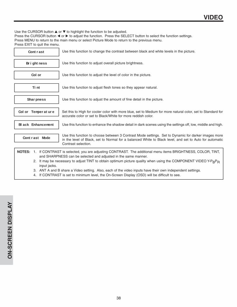
Picture Mode Select between the two picture modes; Day and Night.Contrast Adjust contrast.Brightness Adjust brightness.Color Adjust color.Tint Adjust tint.Sharpness Adjust sharpness.Color Temperature Set this to High for less intense color with more blue, set to Medium
for natural color, set to Standard for standard colors or Black and White for more reddish color.
Black Enhancement Adjust shadow detail in dark screens.Contrast Mode Choose between Dynamic for darker images more in the level of black,
Normal for a balanced white to black levels and Auto for automatic contrast selection.
Reset Video Settings Choose the Reset Video settings.Color Management Adjust and balance individual colors to make either deeper or more
pure according to preference.Color Decoding Adjust the percentage of Red, Green and Color according to preference.Auto Color The AUTO COLOR function automatically monitors and adjusts the
color to maintain constant color levels even after a program or channel changes. It also maintains natural flesh tones while preserving fidelity of background colors.
Noise Reduction Reduces conspicuous noise in the picture.Auto Movie Mode Turn ON/OFF the 3:2 Pulldown detection feature.
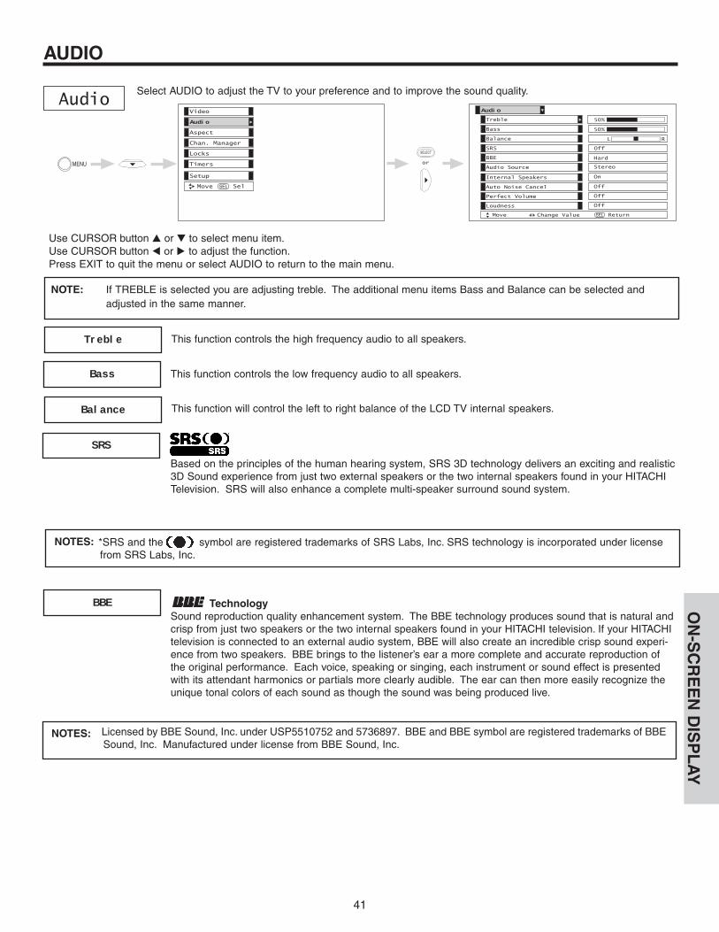
Treble Adjust the treble.Bass Adjust the bass.Balance Adjust the balance.SRS Select SRS settings (Off, Wide, Normal)BBE Select BBE settings (Off, Soft, Hard)Audio Source Select between three Audio Sources.Internal Speakers Select internal or external speakers.Auto Noise Cancel Eliminates the noise between stations.Perfect Volume Adjust volume in fixed setting.Loudness Adjust Loudness.
4:3 Standard4:3 Expanded4:3 Zoom 1
Choose the picture format aspect ratio.4:3 Zoom 216:9 Standard16:9 Zoom
Video
Audio
Aspect
ON
-SC
RE
EN
DIS
PL
AY

36
ON-SCREEN DISPLAY (OSD)
Ant A View/edit Channel ID, Scan, and Lock settings in antenna A.Ant B View/edit Channel ID, Scan, and Lock settings in antenna B.
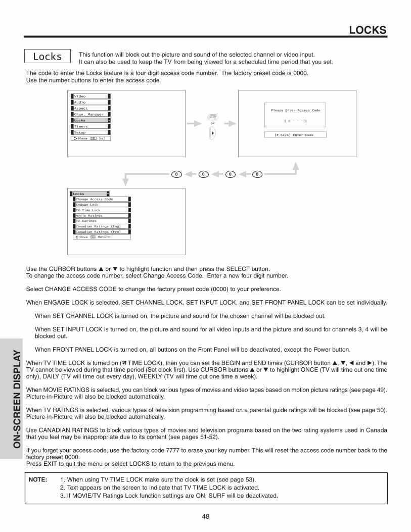
Change Access Code Change Lock access code.Engage Lock Choose to lock channel, video input, and/or front panel.TV Time Lock Set specific time to Lock TV.
Movie RatingsBlock various types of movies and video types based on motion picture ratings.
TV RatingsBlock various types of movies and television programming based on a parental guide ratings.
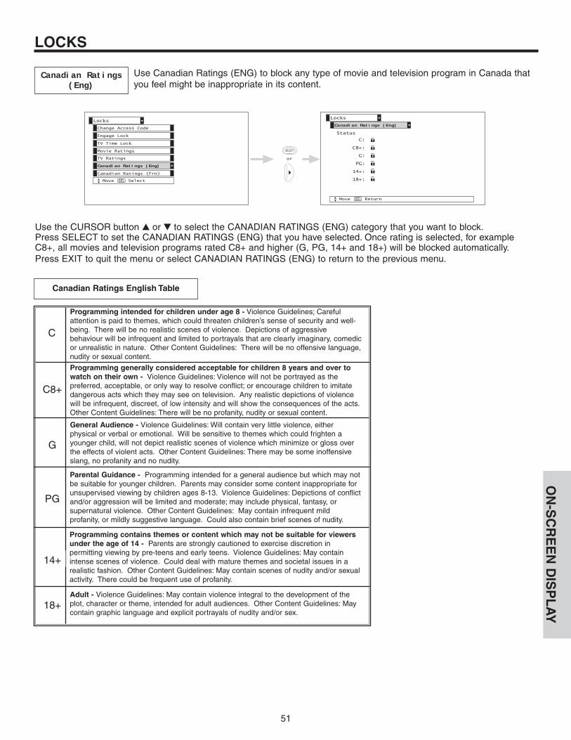
Canadian Ratings (ENG)Block various types of movies and television programming based on the Canadian ratings system.
Canadian Ratings (FRN)Block various types of movies and television programming based on the Canadian French ratings system.
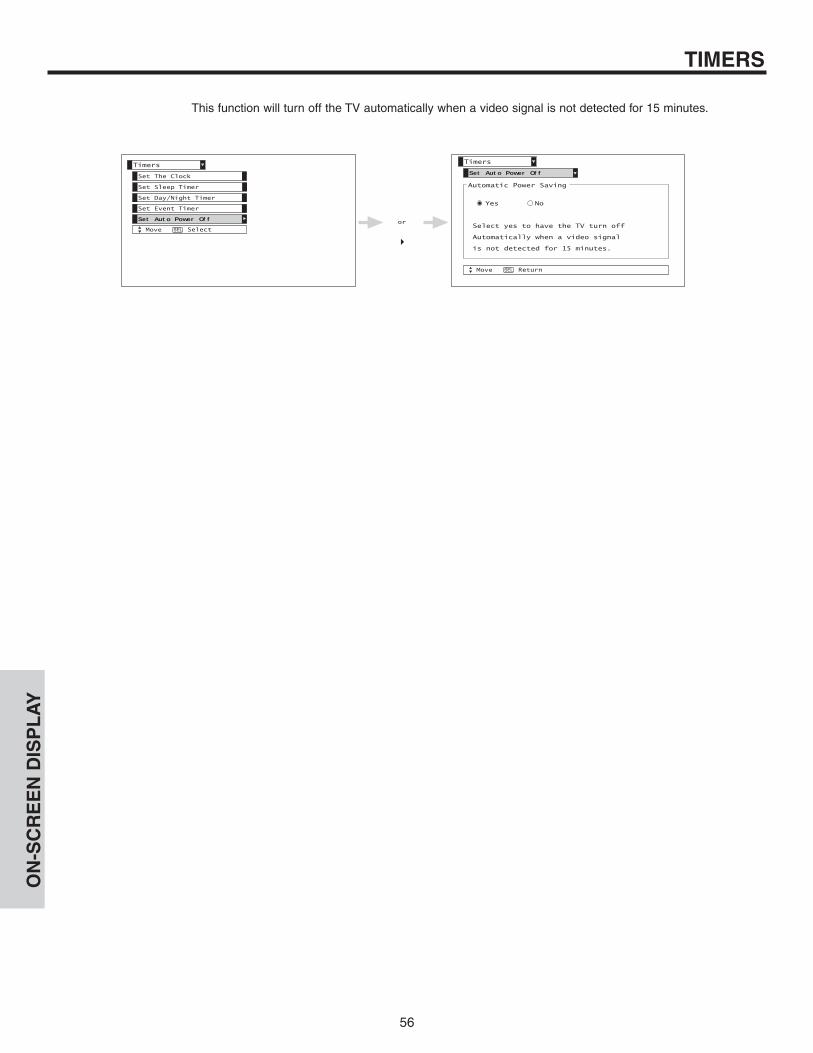
Set the Clock Set Clock Settings.Set Sleep Timer Set Sleep Timer intervals (30 min. intervals, 00:30-3:00).Set Day/Night Timer Set Day/Night picture mode settings.Set Event Timer Set viewing reservation for TV programs.Set Auto Power Off Set TV to turn off automatically when a video signal is not detected for 15
minutes.
Menu Preference Choose English, French, or Spanish text.Screen Saver Set the Screen Saver.Set The Inputs Label Video Inputs , VCR, DVD, etc.Set Black Side Panel Set the gray side bars on/off when watching 4:3 signals in standard mode.Set Closed Captions Feature to display dialogue/text.Set Monitor Out Set Monitor Out source.Set AV Control Select to set RS232C feature.
ChannelManager
Locks
Setup
Timers
ON
-SC
RE
EN
DIS
PL
AY


62
LAMP REPLACEMENT
Lamp ReplacementAfter extended use, if the TV picture turns dark, the color looks unusual or LAMP INDICATOR lightturns on, then it is time to replace the lamp with a new lamp.
Lamp LifeThe lamp life may vary based on usage of the LCD Rear PTV. Turning on and off frequently mayshorten the life of the lamp.
WARNING:The lamp gets very hot! The lamp may explode if improperly handled. To avoid injury, please observe the follow-ing precautions.
• Do not open lamp compartment or attempt to remove lamp assembly unless the lamp assembly is being replaced.• Unplug the product’s power cord from the AC outlet before attempting to replace the lamp assembly.• If the lamp is in use when failure occurs or if the lamp has exploded, wait at least 30-45 minutes for the lamp to
cool before opening the lamp compartment or touching the lamp assembly or any broken pieces.• Broken lamp pieces can cause injury. Handle with gloves to avoid cuts.• Do not place any foreign objects inside the lamp compartment.• When installing a new lamp, follow handling instruction included with the new lamp. Do not touch glass surface of
new lamp.• This product contains lead and a lamp that contains mercury. Dispose of this product and its lamp in accordance
with applicable environmental laws. For lamp recycling and disposal information, go to www.lamprecycle.org. Forproduct recycling and disposal information, contact your local government agency or the Electronic IndustriesAlliance at www.eiae.org (in the US) or the Electronic Product Stewardship Canada at www.epsc.ca (in Canada).For more information, call “1-800-HITACHI.”
CAUTION!
A ”LAMP” indicator will light when lamp becomes hot. Unplug product’s power cord from the AC outlet and allowlamp to cool for at least 30-45 minutes. If “LAMP” indicator is still lit, please contact your authorized service center (see page 70-71).
NOTES:• Contact your Hitachi dealer for a new lamp unit. Using other lamps may cause damage to the TV Set.
LAMP TYPE: LM500 / LAMP PART # UX21513• When replacing the lamp, let it cool down completely, for approximately 30 to 45 minutes after the power has
been switched off and A.C. cord has been unplugged.• Do not touch the glass of the new lamp or make it dirty which can shorten the life of the lamp and reduce the
picture quality.• Keep the lamp out of the reach of children and away from flammable materials.• Do not pour water onto the removed lamp or put any object inside the lamp.• Once the lamp is removed, do not put flammable materials and metal objects inside the lamp receptacle on
the TV set. Do not touch the receptacle.• Install the new lamp securely, otherwise the picture may become dark or it may cause severe overheating.• Install the lamp cover correctly, otherwise power will not come on.
LA
MP
RE
PL
AC
EM
EN
T

63
LAMP REPLACEMENT
120V
FRONT COVER
1. Turn off the power button and unplug the power cord.
CAUTION: THE LAMP IS VERY HOT AND MAY CAUSE FIRE OR SEVERE BURNS. WAIT AT LEAST 30~45MINUTES TO ALLOW THE LAMP TO COOL BEFORE PROCEEDING WITH LAMP REMOVAL.
LAMP COMPARTMENT
2. Remove the front cover from the TV set. This is held by a snap on. Pull the front cover outwards until the quick snap on disengages.
NOTE: This product contains lead and a lamp that contains mercury. Dispose of this product and its lamp in accordance withapplicable environmental laws. For lamp recycling and disposal information, go to www.lamprecycle.org. For productrecycling and disposal information, contact your local government agency or the Electronic Industries Alliance atwww.eiae.org (in the US) or the Electronic Product Stewardship Canada at www.epsc.ca (in Canada).For more information, call “1-800-HITACHI.”
LA
MP
RE
PL
AC
EM
EN
T

64
LAMP REPLACEMENT
SCREW
LAMP COVER
PHILLIP HEADSCREW DRIVER
3. Remove the screw securing the lamp cover with a Phillips head screw driver as shown. Remove the lamp cover.
HANDLEREMOVE SCREWS
HANDLE LAMP UNIT
4. Remove the two screws that hold the lamp in place. Remove the lamp unit by holding the lamp handle, then pulling outwards.Exercise caution when removing the lamp unit to avoid injury to your fingers.
NOTE: DO NOT PUT YOUR HAND IN THE LAMP STORAGE AREA AFTER THE LAMP UNIT ISREMOVED, YOU MAY GET BURNED.
5. Replace with the new lamp.Place the removed lamp into the empty box of the replacement lamp. Do not touch the front glass of the new lamp or its receptacle. This may shorten the life of the lamp and reduce the picture quality.• Push the lamp unit back to its original position.• Tighten the screws firmly on the lamp unit. If they are loose, the TV may not operate correctly.
HANDLE
LAMP UNIT
TIGHTEN THE SCREWS
HANDLE
CAUTION: THE LAMP IS VERY HOT AND MAY CAUSE FIRE OR SEVERE BURNS. WAIT AT LEAST 30~45MINUTES TO ALLOW THE LAMP TO COOL BEFORE PROCEEDING WITH LAMP REMOVAL.
LA
MP
RE
PL
AC
EM
EN
T

65
LAMP REPLACEMENT
6. Without installing the lamp cover, the power will be off and the Lamp Indicator will flash (see page 8). Be sure to install the lampcover by re-engaging the two clips and tighten the screws before turning the power on, otherwise it may cause unusual colors.
SCREW
LAMP COVER
PHILLIP HEADSCREW DRIVER
NOTE: IF POWER IS CONNECTED BEFORE THE LAMP COVER IS INSTALLED, THE POWER WILLBE OFF AND THE LAMP INDICATOR WILL FLASH (SEE PAGE 8 ).
7. Install the front cover as shown below. Put the front cover back in and align the snap on quick connect then push inwards holdingthe left and right side of the front cover until you hear a snap. Push the other snap on gently to make a good fit.
8. Plug power cord into AC outlet and turn on the power switch.
120V
NOTE: This product contains lead and a lamp that contains mercury. Dispose of this product and its lamp in accordance withapplicable environmental laws. For lamp recycling and disposal information, go to www.lamprecycle.org. For productrecycling and disposal information, contact your local government agency or the Electronic Industries Alliance atwww.eiae.org (in the US) or the Electronic Product Stewardship Canada at www.epsc.ca (in Canada).For more information, call “1-800-HITACHI.”
LA
MP
RE
PL
AC
EM
EN
T

66
CARE OF YOUR HITACHI TELEVISIONAND YOUR REMOTE CONTROL
DO
Dust the screen and cabinet with a soft cloth.
Clean the screen with a soft cloth moistened in warm water and dry with a soft cloth. A mild soap may be used ifthe screen is extremely dirty.
Place your Television away from extreme heat, humidity, and extremely dusty places.
Remove the plug from the wall outlet if your Television will not be used for a long period of time, for instances,when you go on vacation.
DO NOT
Do not clean your screen or cabinet with strong cleaners, polishes or a chemically treated cloth.
Do not place rubber or vinyl products or cellophane tape on your Television.
Do not touch the screen too often.
Do not subject the remote control to shocks such as dropping it on the floor, etc. Physical damage to the precisionparts may result.
Avoid placing the remote control in a high humidity place or getting it wet. Do not leave it on or near a heater.Excessive heat or moisture may cause the unit to cease operation.
When the batteries run down, remote control operation will become erratic or possibly stop altogether. Replace theold batteries with two new “AA” size batteries as soon as possible to preserve the remote control precodes that wereset for the devices. Pressing a remote control button with a “DEAD” battery might erase all precodes in memory. Donot use an old battery with a new battery.
Exposure of the viewing screen to prolonged direct sunlight or heat may cause the screen to permanently warp,resulting in a distorted picture.

67
RECEPTION PROBLEMS
• IGNITION NOISE:Black spots or horizontal streaks may appear, picture may flutter or drift.Usually caused by interference from automobile ignition systems, neonlamps, electrical drills, and other electrical appliances.
• GHOSTS:Ghosts are caused by the television signal following two paths. One is thedirect path and the other is reflected from tall buildings, hills or some otherobjects. Changing the direction or position of the antenna may improvereception. Ghosting may also be caused by defects in the antenna systemsuch as unshielded leads or connecting several sets to the same antennawithout using multiple antenna couplers.
• SNOW:If your receiver is located in the fringe area of a television station where thesignal is weak, your picture may be marred by the appearance of smalldots. When the signal is extremely weak, it may be necessary to install aspecial antenna to improve the picture.
• RADIO FREQUENCY INTERFERENCE:The interference produces moving ripples or diagonal streaks, and in somecases, causes loss of contrast in the picture.
N O T E : T h e T V s e t c a n g e n e r a t e s o u n d d i s t o r t i o n i n e x t e r n a l d e v i c e s s u c h a s a r a d i o . P l e a s e s e p a r a t e r a d i o e q u i p m e n t f r o m t h e T V s e t t o a c o n s i d e r a b l e d i s t a n c e .

USEFUL INFO
68
HITACHI Liquid Crystal Display incorporates advanced power surge protection technology designed to protect againstcomponent or circuit damage due to external or internal voltage power surges.
IF YOUR TELEVISION SHOULD APPEAR TO HAVE A LOSS OF POWER, PLEASE FOLLOW THIS PROCEDURE:
1. Press the power switch (ON/OFF switch) once.2. If there is still no power, wait 30 seconds and press the power switch again.3. If there is still no power, unplug the power cord from the wall.Wait 30 seconds and plug the power cord back in.
Press the power switch again.
This protective technology should provide for years of lasting entertainment from your HITACHI Liquid Crystal Display.
SYMPTOMS CH
EC
K T
HE
SE
ITE
MS
AN
D
TRY
THE
SE
AD
JUS
TME
NTS
No Picture, no sound
Sound OK, picture poor
Picture OK, sound poor
Picture blurred
Lines or streaks in picture
Poor reception on some channels
Picture rolls vertically
No color
Poor color
� � � � � � �
�
�
�
�
�
� � � � � � �
� � � � � �
� � � � �
� � � � �
� � � � �
� �
� � � �
� � � �
�
� �
Be
sure
ext
erna
l con
nect
ion
is c
orre
ct
Be
sure
pow
er c
ord
is p
lugg
ed in
Be
sure
TV
is s
witc
hed'
'ON
"
Try
anot
her c
hann
el (s
tatio
n tro
uble
)
Che
ck a
nten
na c
onne
ctio
ns (b
ack
of T
V)
Che
ck a
nten
na fo
r bro
ken
lead
-in w
ire
Che
ck fo
r loc
al in
terfe
renc
e
Che
ck o
utsi
de a
nten
naA
djus
t Con
trast
con
trol
Adj
ust B
right
ness
con
trol
Adj
ust C
olor
con
trol
Adj
ust T
int c
ontro
lA
djus
t Vol
ume
cont
rol
Rep
lace
Lam
p
Dark Picture ���

USEFUL INFO
69
Inputs:
• Power Input . . . . . . . . . . . . . .AC 120V, 60Hz
• Stand-by Power . . . . . . . . . . . . . . . . . . .0.6W• Power Consumption
- Refer to rear panel at the back of the T.V.• Antenna input impedance . . . . . . . . .75 Ohm• Channel coverage . . . . . . . . . . . . . . . .181ch.
VHF-Band . . . . . . . . . . . . . . . . . . . . . .2 ~ 13UHF-Band . . . . . . . . . . . . . . . . . . . . .14 ~ 69CATV Mid Band . . . . . . . . . . . . . . .A-5 ~ A-1
. . . . . . . . . . . . . . . . . . . . . . . . . . . .A-ISuper Band . . . . . . . . . . . . . . . . . . . . . .J-WHyper Band . . . . . . . . . . . . . . . .W+1 - W+28Ultra Band . . . . . . . . . . . . . . . .W+29 - W+84
• Video . . . . . . . . . . . . . . . . .1.0Vp-p, 75 Ohm
• S-VideoLuminance (Y) . . . . . . . . . . .1.0Vp-p, 75 OhmChrominance (C) . . . . . . .0.286Vp-p, 75 Ohm
• Component VideoLuminance (Y) . . . . . . . . . . . . . . .1.0Vp-p, 75 OhmChrominance (PB/PR) . . . . . . . . .0.7Vp-p, 75 Ohm
• Audio input Impedance . . . . . . . . . .47k Ohm
• Average input level . . . . . . . . . . . . . . . . .470mVrms• HDMI . . . . . . . . . . . . . . . . . . . . . . . . . . .HDMI 19pin
Dimensions:
50V525E 60V525E• Height (in.) 35 1/2 40 1/4
(mm) 901.0 1023.0
• Width (in.) 54 5/8 63 3/8(mm) 1387.0 1609.0
• Depth (in.) 16 3/8 20 1/2(mm) 415.0 520.0
• Weight (lbs.) 114.0 128.5(kg) 51.7 58.3
NOTE: Due to improvements, specifications in this operatingguide are subject to change without notice.
Outputs:
• Video . . . . . . . . . . . . . . . . . . . . . . . . . . . . . . . . . . .1.0Vp-p. 75 Ohm• Audio (Fixed) . . . . . . . . . . . . . . . . . . . . . . . . . . .470mVrms, 1k Ohm• S-Video
Luminance (Y) . . . . . . . . . . . . . . . . . . . . .1.0Vp-p, 75 OhmChrominance (C) . . . . . . . . . . . . . . . . .0.286Vp-p, 75 Ohm
• Six Aspect Modes• Closed Caption Decoder• 2-Tuner Picture in Picture• 2 Antenna Inputs (Either for Analog/Digital)• Video Input Sensor• 3 Dimensional Y/C Comb Filter• Compatible with 1080i, 720p, 480p and 480i input signals.• HDMI (High Definition Multimedia Interface) (High Bandwidth Digital Content Protection V1.1 compatible).• Technology.
*Licensed by BBE Sound, Inc. under USP5510752 and 5736897. BBE and BBE symbol are registered trademarks of BBE Sound, Inc. Manufactured under license from BBE Sound, Inc.
• Technology.*SRS and symbol are trademarks of SRS Labs, Inc. SRS technology is incorporated under license from SRS Labs, Inc.
• Technology
*HDMI, the HDMI logo and High-Definition Multimedia Interface are trademarks or registered trademarks of HDMI Licensing LLC.
Features:• Superfine Picture Quality
1280 Line Horizontal Resolution• Remote (Controls many PVR/VCR brands, cable boxes, satellite boxes, and other audio equipment).• New Easy-to-Use (3-Language) On-Screen Menu• Full Set of Input Jacks, including S-VIDEO• COMPONENT VIDEO: Y-PB/PR

USEFUL INFO
70
Hitachi America, LTD.Home Electronics DivisionHitachi has made every effort to assure you hours of trouble free operation from your unit. However, should you require service,a network of Hitachi Authorized Service Facilities has been established in all 50 states and Puerto Rico. Each facility will provideyou with convenient and expedient assistance. Our service hotline operator will direct you to the Hitachi Authorized Service Facilitynearest you. Just present proof of purchase and/or delivery receipts to the Hitachi Authorized Service Facility, and service will berendered in accordance with the terms of the limited warranty as stated on your warranty card or operating guide.
Should you have any questions regarding warranty, service, operation, or technical assistance, please contact:
To locate an authorizedHITACHI service facilityin the continental U.S.A.and Canada,
DIAL TOLL FREE7 days a week, 24 hours a day
(1-800-448-2244)
Hitachi America, LTD.Home Electronics Division
900 Hitachi WayChula Vista, CA 91914-3556

USEFUL INFO
71
In Canada:1-800-HITACHI
(1-800-448-2244)
Monday - Friday EST 9:00am - 7:00pmSaturday EST 9:00am - 5:00pm
Hitachi Canada, LTD.Digital Media Division
Should you have any questions regarding warranty, service, operation, or technical assistance, please contact:
Look for your French Manual on the outside of the box.If the manual is missing, call
for a copy.
1-800-HITACHI(1-800-448-2244)
Au Canada:1-800-HITACHI
(1-800-448-2244)
Lundi - Vendredi L’EST 9:00am - 7:00pmSamedi L’EST 9:00am - 5:00pm
Pour de plus amples renseignements sur le service durant la période couverte par la garantie, sur le fonction-nement ou pour de l’assistance technique communiquez avec:
La version français de votre manual se trouve a l’exterieur de la boîte.Si le manuel est manquant, coposez le
pour obenir votre copie.
1-800-HITACHI(1-800-448-2244)
HITACHI CANADA, LTD.6740 Campobello Road
Mississauga, ON L5N 2L8
72
INDEX
AAccessories . . . . . . . . . . . . . . . . . . . . . . . . . . . . . . . . . . . .4Antennas (Connecting) . . . . . . . . . . . . . . . . . . . . . . . . .5, 6Aspect Ratio . . . . . . . . . . . . . . . . . . . . . . . . . . . . . . .22, 43Audio (Sound Enhancement)
SRS . . . . . . . . . . . . . . . . . . . . . . . . . . . . . . . . . . . . .41BBE . . . . . . . . . . . . . . . . . . . . . . . . . . . . . . . . . . . . .41
Audio Settings . . . . . . . . . . . . . . . . . . . . . . . . . . . . . .41-42Audio Source . . . . . . . . . . . . . . . . . . . . . . . . . . . . . . . . .42Auto Color . . . . . . . . . . . . . . . . . . . . . . . . . . . . . . . . . . . .40Auto Noise Cancel . . . . . . . . . . . . . . . . . . . . . . . . . . . . .42
BBalance . . . . . . . . . . . . . . . . . . . . . . . . . . . . . . . . . . . . . .41Bass . . . . . . . . . . . . . . . . . . . . . . . . . . . . . . . . . . . . . . . .41Black Enhancement . . . . . . . . . . . . . . . . . . . . . . . . . . . .38Brightness . . . . . . . . . . . . . . . . . . . . . . . . . . . . . . . . . . . .38
CChannel Manager . . . . . . . . . . . . . . . . . . . . . . . . . . .44-47
Auto Channel Scan . . . . . . . . . . . . . . . . . . . . . . . . .45Channel Source . . . . . . . . . . . . . . . . . . . . . . . . . . . .44
ClockTime . . . . . . . . . . . . . . . . . . . . . . . . . . . . . . . . . . . . .53Date . . . . . . . . . . . . . . . . . . . . . . . . . . . . . . . . . . . . .53
Closed CaptionsAnalog Captions . . . . . . . . . . . . . . . . . . . . . . . . . . .60
Color Management . . . . . . . . . . . . . . . . . . . . . . . . . . . . .39Color Temperature . . . . . . . . . . . . . . . . . . . . . . . . . . . . .38Color . . . . . . . . . . . . . . . . . . . . . . . . . . . . . . . . . . . . . . . .38Contrast . . . . . . . . . . . . . . . . . . . . . . . . . . . . . . . . . . . . . .38
DDVI Input . . . . . . . . . . . . . . . . . . . . . . . . . . . . . . . .18
EEvent Timer . . . . . . . . . . . . . . . . . . . . . . . . . . . . . . . . . . .55
HHDMI . . . . . . . . . . . . . . . . . . . . . . . . . . . . . . . . . . . . .11, 18
IInput Setup . . . . . . . . . . . . . . . . . . . . . . . . . . . . . . . . . . .59Inputs Button . . . . . . . . . . . . . . . . . . . . . . . . . . . . . . . . . .23
LLamp
Lamp Indicator . . . . . . . . . . . . . . . . . . . . . . . . .8Lamp Replacement . . . . . . . . . . . . . . . . . .62-65
LanguageMenu Language . . . . . . . . . . . . . . . . . . . . . . . . . . . .57
LocksChange Access Code . . . . . . . . . . . . . . . . . . . . . . .48Channel Lock . . . . . . . . . . . . . . . . . . . . . . . . . . . . . .48Input Lock . . . . . . . . . . . . . . . . . . . . . . . . . . . . . . . .48Front Panel Lock . . . . . . . . . . . . . . . . . . . . . . . . . . .48TV Time Lock . . . . . . . . . . . . . . . . . . . . . . . . . . . . . .48Movie Ratings . . . . . . . . . . . . . . . . . . . . . . . . . . . . .49TV Ratings . . . . . . . . . . . . . . . . . . . . . . . . . . . . . . . .50TV Ratings (Canadian - English) . . . . . . . . . . . . . . .51
TV Ratings (Canadian - French) . . . . . . . . . . . . . . .52Loudness . . . . . . . . . . . . . . . . . . . . . . . . . . . . . . . . . . . .42
MMenu Preference
Language . . . . . . . . . . . . . . . . . . . . . . . . . . . . . . . . .57Background . . . . . . . . . . . . . . . . . . . . . . . . . . . . . . .58
Monitor Out . . . . . . . . . . . . . . . . . . . . . . . . . . . . . . . .10, 61
NNoise Reduction . . . . . . . . . . . . . . . . . . . . . . . . . . . . . . .40
PPerfect Volume . . . . . . . . . . . . . . . . . . . . . . . . . . . . . . . .42Picture Mode . . . . . . . . . . . . . . . . . . . . . . . . . . . . . . . . . .37Picture-in-Picture (PIP) . . . . . . . . . . . . . . . . . . . . . . .26-28Picture-outside-Picture (POP) . . . . . . . . . . . . . . . . . . . . .26Power Button . . . . . . . . . . . . . . . . . . . . . . . . . . . . . . . . . . .7Power Indicator . . . . . . . . . . . . . . . . . . . . . . . . . . . . . . . . .8
RRemote Control
Functions . . . . . . . . . . . . . . . . . . . . . . . . . . . . . .20-33Programming Codes . . . . . . . . . . . . . . . . . . . . . . . .33Installing Batteries . . . . . . . . . . . . . . . . . . . . . . . . . . .4
SSharpness . . . . . . . . . . . . . . . . . . . . . . . . . . . . . . . . . . . .38Speakers . . . . . . . . . . . . . . . . . . . . . . . . . . . . . . . . . . . . .42
Connecting External Speakers . . . . . . . . . . . . . .5, 14
TTemperature Indicator . . . . . . . . . . . . . . . . . . . . . . . . . . . .8Time . . . . . . . . . . . . . . . . . . . . . . . . . . . . . . . . . . . . . . . .53Timers . . . . . . . . . . . . . . . . . . . . . . . . . . . . . . . . . . . .53-56Tint . . . . . . . . . . . . . . . . . . . . . . . . . . . . . . . . . . . . . . . . .38Treble . . . . . . . . . . . . . . . . . . . . . . . . . . . . . . . . . . . . . . .41
VVertical Position . . . . . . . . . . . . . . . . . . . . . . . . . . . . . . . .43Video Settings . . . . . . . . . . . . . . . . . . . . . . . . . . . . . .37-40

73
NOTES

74
NOTES

75
NOTES

QR64311