lct08 - qbit-optronics.com file1 lct08 instruction manual notice the operation of the leak detector...
TRANSCRIPT
1
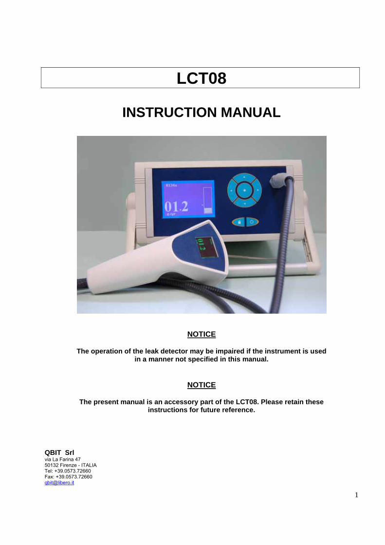
LCT08
INSTRUCTION MANUAL
NOTICE
The operation of the leak detector may be impaired if the instrument is used in a manner not specified in this manual.
NOTICE
The present manual is an accessory part of the LCT08. Please retain these instructions for future reference.
QBIT Srl via La Farina 47 50132 Firenze - ITALIA Tel: +39.0573.72660 Fax: +39.0573.72660 [email protected]

2
TABLE OF CONTENTS GENERAL NOTICES . . . . . . . . . . . . . . . . . . . . . . . . . . . . . . . . . . . . . . . . . . . . . . . . . . . . . . . . . . 5 FOREWARD. . . . . . . . . . . . . . . . . . . . . . . . . . . . . . . . . . . . . . . . . . . . . . . . . . . . . . . . . . . . . . . . . 5 1. UNPACKING AND INITIAL CHECKS. . . . . . . . . . . . . . . . . . . . . . . . . . . . . . . . . . . . . . . . . . . . 5 2. OPERATION ENVIRONMENT . . . . . . . . . . . . . . . . . . . . . . . . . . . . . . . . . . . . . . . . . . . . . . . . .5 3. LIABILITY. . . . . . . . . . . . . . . . . . . . . . . . . . . . . . . . . . . . . . . . . . . . . . . . . . . . . . . . . . . . . . . . . .5 4. WARRANTY. . . . . . . . . . . . . . . . . . . . . . . . . . . . . . . . . . . . . . . . . . . . . . . . . . . . . . . . . . . . . . . .6 CHAPTER I – SAFETY. . . . . . . . . . . . . . . . . . . . . . . . . . . . . . . . . . . . . . . . . . . . . . . . . . . . . . . . . 7 I.1. GENERAL SAFETY. . . . . . . . . . . . . . . . . . . . . . . . . . . . . . . . . . . . . . . . . . . . . . . . . . . . . . . . .7 I.2. SAFETY PRECAUTIONS. . . . . . . . . . . . . . . . . . . . . . . . . . . . . . . . . . . . . . . . . . . . . . . . . . . . 7 I.2.1. Instrument safe location . . . . . . . . . . . . . . . . . . . . . . . . . . . . . . . . . . . . . . . . . . . . . . . . . . . .7 I.2.2. AC power and grounding . . . . . . . . . . . . . . . . . . . . . . . . . . . . . . . . . . . . . . . . . . . . . . . . . . .7 I.2.3. Proper use . . . . . . . . . . . . . . . . . . . . . . . . . . . . . . . . . . . . . . . . . . . . . . . . . . . . . . . . . . . . . .7 I.2.4. In case of malfunction . . . . . . . . . . . . . . . . . . . . . . . . . . . . . . . . . . . . . . . . . . . . . . . . . . . . . 8 I.2.5. Cleaning. . . . . . . . . . . . . . . . . . . . . . . . . . . . . . . . . . . . . . . . . . . . . . . . . . . . . . . . . . . . . . . . 8 CHAPTER II – SPECIFICATIONS . . . . . . . . . . . . . . . . . . . . . . . . . . . . . . . . . . . . . . . . . . . . . . . . 9 II.1. MEASUREMENT SPECIFICATIONS . . . . . . . . . . . . . . . . . . . . . . . . . . . . . . . . . . . . . . . . . . 9 II.2. GENERAL SPECIFICATIONS. . . . . . . . . . . . . . . . . . . . . . . . . . . . . . . . . . . . . . . . . . . . . . . . 9 II.3. TECHNICAL TERMS . . . . . . . . . . . . . . . . . . . . . . . . . . . . . . . . . . . . . . . . . . . . . . . . . . . . . . 10 II.4. DISPOSAL . . . . . . . . . . . . . . . . . . . . . . . . . . . . . . . . . . . . . . . . . . . . . . . . . . . . . . . . . . . . . . 10 CHAPTER III – FUNCTIONAL OVERVIEW . . . . . . . . . . . . . . . . . . . . . . . . . . . . . . . . . . . . . . . . 11 III.1. REAR PANEL. . . . . . . . . . . . . . . . . . . . . . . . . . . . . . . . . . . . . . . . . . . . . . . . . . . . . . . . . . . .11 III.1.1 Main switch. . . . . . . . . . . . . . . . . . . . . . . . . . . . . . . . . . . . . . . . . . . . . . . . . . . . . . . . . . . . 11 III.1.2 Fuses. . . . . . . . . . . . . . . . . . . . . . . . . . . . . . . . . . . . . . . . . . . . . . . . . . . . . . . . . . . . . . . . . 11 III.1.3 USB connector. . . . . . . . . . . . . . . . . . . . . . . . . . . . . . . . . . . . . . . . . . . . . . . . . . . . . . . . . . 11 III.1.4 Sample gas exhaust . . . . . . . . . . . . . . . . . . . . . . . . . . . . . . . . . . . . . . . . . . . . . . . . . . . . . 11 III.1.5 External speakers connector. . . . . . . . . . . . . . . . . . . . . . . . . . . . . . . . . . . . . . . . . . . . . . . .11 III.2. CONTROL PANEL. . . . . . . . . . . . . . . . . . . . . . . . . . . . . . . . . . . . . . . . . . . . . . . . . . . . . . . . 12 III.2. 1. Liquid crystal display (LCD). . . . . . . . . . . . . . . . . . . . . . . . . . . . . . . . . . . . . . . . . . . . . . . 13 III.2. 2. Keypad. . . . . . . . . . . . . . . . . . . . . . . . . . . . . . . . . . . . . . . . . . . . . . . . . . . . . . . . . . . . . . . 13 III.3. CORD. . . . . . . . . . . . . . . . . . . . . . . . . . . . . . . . . . . . . . . . . . . . . . . . . . . . . . . . . . . . . . . . . . 13 III.4. HANDPIECE. . . . . . . . . . . . . . . . . . . . . . . . . . . . . . . . . . . . . . . . . . . . . . . . . . . . . . . . . . . . . 13 CHAPTER IV – PREPARING FOR OPERATION. . . . . . . . . . . . . . . . . . . . . . . . . . . . . . . . . . . . 14 IV.1. LOCATION . . . . . . . . . . . . . . . . . . . . . . . . . . . . . . . . . . . . . . . . . . . . . . . . . . . . . . . . . . . . . 14 IV.1. 1. Temperature fluctuations. . . . . . . . . . . . . . . . . . . . . . . . . . . . . . . . . . . . . . . . . . . . . . . . . 14 IV.2. INITIAL OPERATION. . . . . . . . . . . . . . . . . . . . . . . . . . . . . . . . . . . . . . . . . . . . . . . . . . . . . .14 CHAPTER V – SYSTEM FUNCTIONALITY. . . . . . . . . . . . . . . . . . . . . . . . . . . . . . . . . . . . . . . . .15 V.1. TURNING THE INSTRUMENT ON. . . . . . . . . . . . . . . . . . . . . . . . . . . . . . . . . . . . . . . . . . . .15 V.2. SYSTEM RESET. . . . . . . . . . . . . . . . . . . . . . . . . . . . . . . . . . . . . . . . . . . . . . . . . . . . . . . . . .15 V.3. AUTO ZERO. . . . . . . . . . . . . . . . . . . . . . . . . . . . . . . . . . . . . . . . . . . . . . . . . . . . . . . . . . . . . 15

3
V.4. MAIN MENU. . . . . . . . . . . . . . . . . . . . . . . . . . . . . . . . . . . . . . . . . . . . . . . . . . . . . . . . . . . . . 15 V.5. OPERATION MODES. . . . . . . . . . . . . . . . . . . . . . . . . . . . . . . . . . . . . . . . . . . . . . . . . . . . . .16 V.5. 1. “Continuous” mode. . . . . . . . . . . . . . . . . . . . . . . . . . . . . . . . . . . . . . . . . . . . . . . . . . . . . . 16 V.5. 2. “Sequence” mode. . . . . . . . . . . . . . . . . . . . . . . . . . . . . . . . . . . . . . . . . . . . . . . . . . . . . . . 16 V.5. 3. “Snapshot” mode. . . . . . . . . . . . . . . . . . . . . . . . . . . . . . . . . . . . . . . . . . . . . . . . . . . . . . . .18 V.6. GAS SETTING . . . . . . . . . . . . . . . . . . . . . . . . . . . . . . . . . . . . . . . . . . . . . . . . . . . . . . . . . . . 18 V.6. 1. Default calibration. . . . . . . . . . . . . . . . . . . . . . . . . . . . . . . . . . . . . . . . . . . . . . . . . . . . . . . 18 V.6. 2. Last calibration. . . . . . . . . . . . . . . . . . . . . . . . . . . . . . . . . . . . . . . . . . . . . . . . . . . . . . . . . .18 V.6. 3. Calibrate on leak. . . . . . . . . . . . . . . . . . . . . . . . . . . . . . . . . . . . . . . . . . . . . . . . . . . . . . . . 18 V.7. ALARM SETTING. . . . . . . . . . . . . ... . . . . . . . . . . . . . . . . . . . . . . . . . . . . . . . . . . . . . . . . . . 19 V.7. 1. Acoustic alarm. . . . . . . . . . . . . . . . . . . . . . . . . . . . . . . . . . . . . . . . . . . . . . . . . . . . . . . . . . 19 V.7. 2. Handpiece alarm. . . . . . . . . . . . . . . . . . . . . . . . . . . . . . . . . . . . . . . . . . . . . . . . . . . . . . . . .19 V.8. TEST SETTING. . . . . . . . . . . . . . . . . . . . . . . . . . . . . . . . . . . . . . . . . . . . . . . . . . . . . . . . . . . 19 V.8. 1. Flow test. . . . . . . . . . . . . . . . . . . . . . . . . . . . . . . . . . . . . . . . . . . . . . . . . . . . . . . . . . . . . . .20 V.8. 1. Temperature test. . . . . . . . . . . . . . . . . . . . . . . . . . . . . . . . . . . . . . . . . . . . . . . . . . . . . . . . 20 V.9. UTILITY SETTING. . . . . . . . . . . . . . . . . . . . . . . . . . . . . . . . . . . . . . . . . . . . . . . . . . . . . . . . . 20 V.9. 1. Units. . . . . . . . . . . . . . . . . . . . . . . . . . . . . . . . . . . . . . . . . . . . . . . . . . . . . . . . . . . . . . . . . . 20 V.9. 2. Warm-up. . . . . . . . . . . . . . . . . . . . . . . . . . . . . . . . . . . . . . . . . . . . . . . . . . . . . . . . . . . . . . .20 V.9. 3. Date. . . . . . . . . . . . . . . . . . . . . . . . . . . . . . . . . . . . . . . . . . . . . . . . . . . . . . . . . . . . . . . . . . 20 V.9. 4. Time. . . . . . . . . . . . . . . . . . . . . . . . . . . . . . . . . . . . . . . . . . . . . . . . . . . . . . . . . . . . . . . . . . 20 V.9. 5. Language. . . . . . . . . . . . . . . . . . . . . . . . . . . . . . . . . . . . . . . . . . . . . . . . . . . . . . . . . . . . . . 20 V.10. PC INTERFACING. . . . . . . . . . . . . . . . . . . . . . . . . . . . . . . . . . . . . . . . . . . . . . . . . . . . . . . . 20 V.10. 1. Memory management. . . . . . . . . . . . . . . . . . . . . . . . . . . . . . . . . . . . . . . . . . . . . . . . . . . . 21 V.10. 2. File name and format. . . . . . . . . . . . . . . . . . . . . . . . . . . . . . . . . . . . . . . . . . . . . . . . . . . . .21 V.10. 3. File management . . . . . . . . . . . . . . . . . . . . . . . . . . . . . . . . . . . . . . . . . . . . . . . . . . . . . . . 22 V.10. 4. Single file handling. . . . . . . . . . . . . . . . . . . . . . . . . . . . . . . . . . . . . . . . . . . . . . . . . . . . . . .22 V.11. SYSTEM TURN-OFF . . . . . . . . . . . . . . . . . . . . . . . . . . . . . . . . . . . . . . . . . . . . . . . . . . . . . . 22 CHAPTER VI – ERRORS AND TROUBLESHOOTING. . . . . . . . . . . . . . . . . . . . . . . . . . . . . . . . .23 VI.1. SYSTEM ERRORS AND MALFUNCTIONS . . . . . . . . . . . . . . . . . . . . . . . . . . . . . . . . . . . . .23 VI.2. ERROR AND MALFUNCTION DESCRIPTION. . . . . . . . . . . . . . . . . . . . . . . . . . . . . . . . . . .23 VI.2. 1. Flow. . . . . . . . . . . . . . . . . . . . . . . . . . . . . . . . . . . . . . . . . . . . . . . . . . . . . . . . . . . . . . . . . . 23 VI.2. 2. Temperature . . . . . . . . . . . . . . . . . . . . . . . . . . . . . . . . . . . . . . . . . . . . . . . . . . . . . . . . . . . 23 VI.2. 3. Infrared sensor not responding . . . . . . . . . . . . . . . . . . . . . . . . . . . . . . . . . . . . . . . . . . . . . 24 VI.2. 4. Infrared sensor needs revision. . . . . . . . . . . . . . . . . . . . . . . . . . . . . . . . . . . . . . . . . . . . . .24 VI.2. 5. Abnormal reference level. . . . . . . . . . . . . . . . . . . . . . . . . . . . . . . . . . . . . . . . . . . . . . . . . . 24 VI.3. TROUBLESHOOTING. . . . . . . . . . . . . . . . . . . . . . . . . . . . . . . . . . . . . . . . . . . . . . . . . . . . . . 24 VI.4. FUSE REPLACEMENT. . . . . . . . . . . . . . . . . . . . . . . . . . . . . . . . . . . . . . . . . . . . . . . . . . . . .25 CHAPTER VII – MAINTENANCE. . . . . . . . . . . . . . . . . . . . . . . . . . . . . . . . . . . . . . . . . . . . . . . . . .26 VII.1. USER MAINTENANCE. . . . . . . . . . . . . . . . . . . . . . . . . . . . . . . . . . . . . . . . . . . . . . . . . . . . .26 VII.1. 1. Cleaning suggestions. . . . . . . . . . . . . . . . . . . . . . . . . . . . . . . . . . . . . . . . . . . . . . . . . . . . 26 VII.1. 2. Paper filter replacement. . . . . . . . . . . . . . . . . . . . . . . . . . . . . . . . . . . . . . . . . . . . . . . . . . 26 VII.2. QUALIFIED PERSONNEL MAINTENANCE. . . . . . . . . . . . . . . . . . . . . . . . . . . . . . . . . . . . .27 CHAPTER VIII – ACCESSORY PARTS. . . . . . . . . . . . . . . . . . . . . . . . . . . . . . . . . . . . . . . . . . . . .28 VIII.1. SYSTEM ACCESSORY PARTS . . . . . . . . . . . . . . . . . . . . . . . . . . . . . . . . . . . . . . . . . . . . .28

4
FIGURE INDEX Fig. III.1 – Rear panel. . . . . . . . . . . . . . . . . . . . . . . . . . . . . . . . . . . . . . . . . . . . . . . . . . . . . . . . . . 12 Fig. III.2 – Control panel. . . . . . . . . . . . . . . . . . . . . . . . . . . . . . . . . . . . . . . . . . . . . . . . . . . . . . . . .12 Fig. III.3 – Handpiece . . . . . . . . . . . . . . . . . . . . . . . . . . . . . . . . . . . . . . . . . . . . . . . . . . . . . . . . . . 13 Fig. V.1 – Main menu. . . . . . . . . . . . . . . . . . . . . . . . . . . . . . . . . . . . . . . . . . . . . . . . . . . . . . . . . . .17 Fig. VII.1 – Paper filter replacement. . . . . . . . . . . . . . . . . . . . . . . . . . . . . . . . . . . . . . . . . . . . . . . .27 TABLE INDEX Table II.1 – Measurement specifications. . . . . . . . . . . . . . . . . . . . . . . . . . . . . . . . . . . . . . . . . . . . .9 Table II.2 – General specifications. . . . . . . . . . . . . . . . . . . . . . . . . . . . . . . . . . . . . . . . . . . . . . . . . 9 Table VI.1 – Troubleshooting . . . . . . . . . . . . . . . . . . . . . . . . . . . . . . . . . . . . . . . . . . . . . . . . . . . .24

5
GENERAL NOTICES QBIT s.r.l. is responsible of safety, reliability and performance only if: . the system is used according to the instructions reported in this manual – regarding both safety precautions and use; . any change, adjustment and maintenence operation is performed by qualified personnel duly authorized by QBIT s.r.l. ; . the leak detector is connected to an electrical system which is consistent with both IEC and local directions;
The system LCT08 is a refrigerant gas leak detector
for industrial use
FOREWARD The following instructions must be carefully read and observed in order to properly install the system and avoid any damage risk. 1. UNPACKING AND INITIAL CHECKS When you receive the instrument, please unpack it promptly and make a visual inspection to make sure that no damage has occurred during shipment and that all the ordered items have been received. If damage was found, immediately file a claim with the carrier. N.B.: by law, any good is shipped at buyer’s risk and, if not clearly stated, without insurance. QBIT is not responsible of any damage following dispatch, freight, unloading and unpacking. 2. OPERATION ENVIRONMENT The operation environment must be consistent with local directives regarding the electrical system and human working area. 3. LIABILITY QBIT warrants, as final seller, that the system is consistent with CE Council Directives N° 2004/108/EC (Electromagnetic Compatibility) and N° 2006/95/EC (Electrical safety of low voltage equipment). The responsibility of use, safety in the working area and any other action rests entirely with the employer, following local laws and European Directive N° 89/391/CEE. The only manufacturer responsibility is that stated by local laws and European Directives. The manufacturer is not responsible for any impairment due to installation, use and maintenance not consistent with the instructions reported in the present manual. The manufacturer is not responsible for the lack of any care and safety precaution necessary to avoid every damage or prejudice.

6
4. WARRANTY QBIT s.r.l. warrants that, at the time of delivery, this product is free from defects or malfunctions, and it conforms substantially to the specifications reported in the present manual. QBIT’s liability is limited to the repair or replacement, at QBIT’s option, of this product or parts thereof returned to seller and shown to QBIT’s reasonable satisfaction to have been defective; provided that written notice of the defect shall have been given by Buyer to QBIT within two (2) years after the date of delivery of this product by QBIT. The warranty does not apply to parts the instruction manual designates as having a limited shelf-life or as being expended in normal use (e.g. filters). Excepting those parts subject to maintenance, disassembly, change or modification to the instrument will void the warranty. Any control, adjustment or procedure different from those reported in the present manual will also void the warranty.

7
CHAPTER I
SAFETY
Safety is essential in the use and maintenance of the equipment. Therefore the present chapter provides important safety information concerning the operation and maintenance of the LCT08 system. I.1. GENERAL SAFETY The system LCT08 is consistent with the following directives: - CE Council Directive 2006/95/EC (Electrical safety of low voltage equipment); - CE Council Directive 2004/108/EC (Electromagnetic Compatibility). I.2. SAFETY PRECAUTIONS Even if the system has been produced in agreement with safety directives, a proper and careful use is very important for safe operation. IN ORDER TO CORRECTLY OPERATE THE SYSTEM, IT IS STRICTLY REQUESTED TO FOLLOW THE SPECIFICATIONS REPORTED IN THE NEXT PARAGRAPHS. I.2. 1. Instrument safe location: Locate the equipment on a flat surface, far from heat sources or strong air flows. For the best operation, the instrument should preferably work in standard clean air, with no refrigerant gas pollution. I.2. 2. AC power and grounding: The instrument is equipped with a power supply accepting 220 VAC, 50/60 Hz standard line input. UNDER NO CIRCUMSTANCES SHOULD THIS INSTRUMENT BE OPERATED WITHOUT CONNECTION TO A PROTECTIVE GROUND. DOING SO CREATES A POTENTIAL SHOCK HAZARD AND IS ALSO A VIOLATION OF ELECTRICAL SAFETY STANDARDS APPLICABLE TO THIS TYPE OF EQUIPMENT. I.2. 3. Proper use: Do not operate this instrument in the presence of flammable liquids, vapors or aerosols. Both when the equipment is working and when it is not in use, avoid to lean the handpiece and the cord on the floor, or anywhere they risk to be bent, crushed and thus damaged. During system operation avoid to obstruct the sniffer tip and the sample gas exhaust on the rear panel. CAREFULLY PREVENT ANY LIQUID TO BE SUCKED UP IN THE SNIFFER;THE INSTRUMENT MAY BE SERIOUSLY DAMAGED.

8
I.2. 4. In case of malfunction: Do not continue to use this equipment if there are any symptoms of malfunction or failure. In the case of such occurrence, unplug the AC power cord, refer to Chapter VI of the present manual and contact technical service. I.2. 5. Cleaning: Use a dry cloth to clean the outside of the case. Do not use soap and water. Do not use blast of compressed air. When the system is not in use, it is suggested to protect the sniffer tip with its plastic cap and set the equipment in a dry, dust free place.

9
CHAPTER II
SPECIFICATIONS
II.1. MEASUREMENT SPECIFICATIONS: The measurement specifications are reported in Table II.1. Table II.1 Detectable gases . . . . . . . . . Measuring head LS-1 . . . . . . . . . . .R134a, R407C Measuring head LS-2. . . . . . . . . . . .R22 Measuring head LS-3. . . . . . . . . . . .CO2 Measuring head LS-4. . . . . . . . . . . .R134a, R404A, R407C, R410A Measuring head LS-5. . . . . . . . . . . .R134a, R404A, R407C, R410A, R22 Measuring head LS-6. . . . . . . . . . . .600a, R290 Measuring head LS-7. . . . . . . . . . . .SF6 Measuring head LS-H. . . . . . . . . . .He, H2 Detection method. . . . . . . . . .Infrared cell Units. . . . . . . . . . . . . . . . . . . g/yr, oz/yr, mBar L/s, Pa M3/s Range. . . . . . . . . . . . . . . . . . 0.0 a 99.9 g/yr Operating modes. . . . . . . . . .Continuous: leak measurement Sequence: leak measurement and storage Snapshot: detection and location of leak Response time. . . . . . . . . . . .< 1 second Sensitivity. . . . . . . . . . . . . . . .0.3 g/yr for R134a Resolution. . . . . . . . . . . . . . . 0.1 g/yr II.2. GENERAL SPECIFICATIONS: The general specifications are reported in Table II.2. Table II.2 Calibration. . . . . . . . . . . . . . . Internal: with factory settings External: with external customer supplied calibrated leak Audio alarm. . . . . . . . . . . . . .At threshold, with frequency proportional to the leak Three levels of volume
Line-Out Mini Jack 3.5 mm for external speakers Flow rate. . . . . . . . . . . . . . . . 110÷130 sccm AC power. . . . . . . . . . . . . . . .220 VAC, 50/60 Hz Power consumption. . . . . . . .30 Watts Fuse. . . . . . . . . . . . . . . . . . . .F2.0AL (250V – 2.0A) X 2 Warm-up time. . . . . . . . . . . . .6 minutes for initial operation 30 minutes to meet specifications Workin temperature. . . . . . . .12°C to 40° C Storage temperature. . . . . . . –20°C to 80° C
10
Ambient humidity. . . . . . . . . . .10% to 80% RH, non-condensing Main screen. . . . . . . . . . . . . . White on blue, LCD 240 x128 pixels Handpiece screen. . . . . . . . . Color, OLED 160 x 128 pixels Case dimensions. . . . . . . . . . 260 x 250 x 120 mm (except adjustable handle bar) Cord length. . . . . . . . . . . . . . .2800 mm Handpiece dimensions. . . . . .180 x 86 x 45 mm Weight. . . . . . . . . . . . . . . . . . 4 kg II.3. TECHNICAL TERMS: MAIN UNIT: main case equipped with main screen, keypad, AC power connector, adjustable handle bar. CORD : flexible cable connecting the main unit with handpiece. HANDPIECE: gun-shaped probe, equipped with pushbutton, screen and stainless steel sniffer, connected with the main unit by the cord. SNIFFER: terminal fitting of the handpiece, consisting of a stainless steel capillary (3 mm external diameter). CALIBRATED LEAK: certified device reproducing a leak of known gas type and rate. II.4. DISPOSAL At the end of lifetime, the system is to be disposed as electronic material, following European Directives 2002/95/EC e 2003/108/EC. The Buyer will contact QBIT s.r.l. to get any instruction about disposal or return of the equipment.

11
CHAPTER III
FUNCTIONAL OVERVIEW
The system LCT08 is a refrigerant gas leak detector for industrial applications. It was studied to allow detection and measurement of very small leaks that may occur in any field or device where refrigerant gases are employed. The state-of-the-art detection method, based on infra-red light absorption, leads to high sensitivity, short response time, reduced ownership costs and long lifetime. The instrument consists of a main unit (with metallic enclosure) equipped with screen and keypad, a flexible cord (stainless steel with non-conductive sheathing) and a plastic handpiece with screen and pushbutton. It is possible to store measurement sequences and to download the corresponding files on a PC via the USB (Universal Serial Bus). An acoustic alarm (with connection for external speakers) is also present, that helps in leak detection and location. Moreover, since it is possible to include two infra-red cells, a large variety of gases can be detected with the same unit. The LCT08 leak detector is excellent for any application in mass production of refrigerators and air conditioners, and for installation and maintenance of large industrial plants. In these fields, the LCT08 leak detector allows production of goods with reduced gas emission, thus contributing to the control of environmental pollution. III.1. REAR PANEL The rear panel is shown in figure III.1. III.1.1. Main switch The AC power can be switched ON and OFF by means of the red switch located on the rear panel. III.1.2. Fuses The two fuses (F2.0AL, 250V - 2.0A) are contained in a compartment below the AC power receptacle. III.1.3. USB connector The USB connector allows to interface leak detector and computer. The measurements, are saved in the system memory and remain available for downloading by means of the application software described in Chapter V. III.1.4. Sample gas exhaust The pneumatic circuitry ends with the sample gas exhaust, consisting in a filtering brass fitting. III.1.5. External speakers connector This connector (Line-Out Mini Jack 3.5 mm) allows wiring of amplified external speakers that can be placed close to the working station.

12
Figure III.1: 1) USB connector, 2) Sample gas exhaust, 3) Fuse compartment, 4) Main switch, 5) External speakers connector. III.2. CONTROL PANEL The control panel (front view, figure III.2), contains a liquid crystal display (LCD) and a keypad with seven membrane pushbuttons.
Figure III.2: 1) LCD, 2) Keypad.
1 2

13
III.2. 1. Liquid crystal display (LCD) The 240 x 128 pixels white-on-blue LCD is used to display measurements, and to change parameters and settings. In case of malfunction, it also shows the user warning and error messages. III.2. 2. Keypad The keypad contains seven membrane pushbuttons; four arrow pushbuttons ( , , , ) surrounding the “enter” pushbutton ( ), the “zero” pushbutton (0) and the “Menu” pushbutton ( ). The detailed description of keypad functionality (depending on the instrument active setting) is reported in Chapter V. III.3. CORD The cord, 2.8 m long, connects the main case with the handpiece. It shields electrical cables and pneumatic circuitry. III.4. HANDPIECE The gun-shaped handpiece (figure III.3) is equipped with a color OLED screen (160 x 128 pixels) and a pushbutton with different functions depending on the instrument active setting (detailed description is reported in Chapter V). The handpiece ends in a stainless steel, 15 cm long, capillary probe (sniffer) with a protective plastic cap. The sniffer is fixed by means of a connector (that can be easily unscrewed) containing a paper filter.
Figure III.3: 1) Stainless steel capillary , 2) OLED color screen.

14
CHAPTER IV
PREPARING FOR OPERATION
NOTICE: ANY CONTROL, ADJUSTMENT OR PROCEDURE DIFFERENT FROM THOSE REPORTED IN THE PRESENT MANUAL MAY CAUSE ERRORS AND/OR INSTRUMENT IMPAIRMENT.
IV.1. LOCATION Locate the equipment on a flat surface, far from heat sources or strong air flows. For the best operation, the instrument should preferably work in standard clean air, with no refrigerant gas pollution. IV.1. 1. Temperature fluctuations Infra-red absorption measurements are, by their own nature, strongly influenced by environmental temperature. Temperature changes usually induce fluctuations in the measure of background concentration. Although the LCT08 has been studied and manufactured so that it has the best temperature stability, it is suggested to install the detector in a place whit minimum temperature variations.
IV.2. INITIAL OPERATION Unpack the leak detector and accessories. Check the presence of the fuse in the fuse compartment (rear panel). Connect the AC power cord to the instrument’s rear panel and then plug the power cord into a nearby AC line connector. UNDER NO CIRCUMSTANCES CAN THIS INSTRUMENT BE OPERATED WITHOUT CONNECTION TO A PROTECTIVE GROUND.
NOTICE Avoid to lean the handpiece and the cord on the floor, or anywhere they risk to be bent, crushed and thus damaged. During system operation avoid to obstruct the sniffer tip and the sample gas exhaust on the rear panel.

15
CHAPTER V
SYSTEM FUNCTIONALITY V.1. TURNING THE INSTRUMENT ON Remove the plastic cap of the sniffer probe. Turn ON the instrument by setting the power switch located on the rear panel. The instrument performs a self-diagnostic check (approximately 10 seconds), while displaying the instrument’s name “LCT08”. If self-diagnostic check is OK, the system gets ready to use and the data display screen appears. If any malfunction is detected, the corresponding error message (Chapter VI) is displayed on the screen. If the warm-up procedure is active (see Utility menu), the instrument enters its warm-up mode and a countdown from 360 seconds is displayed; during this time the keypad is not active. The default mode of operation initially selected at the factory is the Continuous Mode, in which the detected leak is continuously displayed (Figure V.1). On the right side of the screen a graphical display of the relative gas level is provided by a bar graph that moves up the screen with increasing gas level. In order to select another mode of operation it is necessary to enter the Main Menu (paragraph V.4). V.2. SYSTEM RESET The system reset can be activated by pressing at the same time the “zero“ key (0) and “Menu” key ( ) on the instrument front panel. V.3. AUTO-ZERO By pressing the “zero“ key (0) on the front panel, the instrument measures and stores the background concentration level which is to be subtracted by leak measurements, until next zero procedure. This function sets the instrument for a precise measurement of the leak level even in presence of polluted air. Since infra-red absorption measurements are, by their nature, influenced by temperature, the leak detector may present small fluctuations in the measure of background concentration during the first 30 minutes after turn on. In order to increase measurement precision, it is suggested to perform the zeroing procedure frequently. ATTENTION. DURING THE AUTO-ZERO PROCEDURE DO NOT PLACE THE SNIFFER CLOSE TO ANY POTENTIAL GAS LEAK OR SOURCE; THIS MAY RESULT IN A WRONG BACKGROUND CONCENTRATION MEASUREMENT. V.4. MAIN MENU The system functionality can be managed by means of a tree-structured menu. To enter and exit the menu press the “Menu” key ( ) on the front panel, whatever the active operation mode. The main menu gives access to five sub-menus, described in detail in the next paragraphs. Figure V.1 shows the complete tree-structured menu.

16
The different menu options can be visited by using the four arrow keys ( , , , ); the cursor position is evidenced by an arrow (→). Setting a choice is performed by pressing the “Enter” key ( ). The active setting is always indicated by reverse color. The system automatically exits the menu if arrow ( , , , ) or “Enter” ( ) keys remain idle for more than 20 seconds. The message “Menu setting” is displayed on the handpiece screen during menu operation. V.5. OPERATION MODES In order to choose the operation mode, press “Menu” ( ) and select the “Set Mode” sub-menu by pressing “Enter” ( ). The LCT08 leak detector can be set by the user in three different operation modes. Note that some of the front panel keys have functions which depend on the active operation mode. V.5. 1. “Continuous” mode When the “Continuous” mode is selected, the instrument continuously detects the presence of gas in the infra-red cell and displays the calculated leak rate. In order to allow precise leak detection also in case of polluted environment, it is suggested to perform the auto-zero procedure with a frequency of few minutes. In the “Continuous” mode, auto-zeroing can be performed either with the “zero” key (0) on the front panel or with the handpiece pushbutton. During auto-zero procedure, the sign “--.-“ is displayed on both screens; the instrument measures and stores the background level which is to be subtracted in leak measurements (until next auto-zero). V.5. 2. “Sequence” mode When the “Sequence” mode is selected, the instrument works as in “Continuous” mode, further allowing the user to store sets of measures, that will be available for downloading to PC (paragraph V.10). Select the “Sequence” mode by pressing “Enter” ( ); the sub-menu “Count number” will be displayed. The user can select the number of measures contained in each file by pressing the two arrow keys ( , ); the selected value N (1≤N≤30) is stored with “Enter” ( ). When the “Sequence” operation mode is active, two indicators “Counter” and “Sum” are also displayed on the screens. In this working mode, the user can store a measure by pressing the handpiece pushbutton; the stored value is displayed for three seconds (on the main screen together with the indication “Save“, while the handpiece screen changes color), the variable “Counter” is increased by one unit and the variable “Sum” is updated to the sum of all the measures already stored in the active file. In order to erase the last stored value it is sufficient to press the arrow key ( ). The whole active file can be deleted by pressing “Enter” ( ). When N data have been stored, the system automatically starts a new sequence to be stored in a new file. File storage is possible up to the memory filling (16 Mb); if N=30, the leak detector can store up to 4000 sequences. When the memory is 85% full, the following warning message is displayed: “WARNING. MEMORY 85% FULL. PLEASE ERASE”. The instrument memory can be erased only using the PC download software (paragraph V.10). .

17
Main Menu
Set Gas
Set Alarms
Set Test
Set Utility
Sequence
Snapshot
Count number
Gas 1 /..../ Gas N
Default calibration
Last calibration
Calibrate on leak
Acoustic
Handpiece
Leak level
Flow test
Temperature test
Units
Warm-up
Date
Time
Language
On
Off
Set Mode
Leak level
Volume
Figure V.1: main menu. Continuous

18
In “Sequence” mode, the auto-zero procedure can be executed by the “zero” key (0) on the front panel only. V.5. 3. “Snapshot” mode When the “Snapshot” mode is selected, the system is normally set in auto-zero state, and the indication “--.-“ is continuously displayed on both screens. Whenever the handpiece pushbutton is pressed, the detector switches to continuous mode until the button is loosened. This working mode is especially useful to detect and locate very small leaks. V.6. GAS SETTING In order to set the instrument for the measurement of one of the available gases (see Table II.1) press the “Menu” key ( ) and select by the “Enter” key ( ) the sub-menu “Set Gas”. Perform the gas choice by the two “Arrow” keys ( , ) and press “Enter” ( ). The leak detector is tested with suitable calibrated leaks by the manufacturer in standard temperature and humidity conditions; this, usually, makes further calibration unnecessary. Anyway, the instrument allows the user to perform a new external calibration for each available gas, provided a suitable calibrated leak is at hand. For a given gas, the new calibration is stored and used for next measurements, until resetting of the factory parameters or performance of a new calibration occurs. When the leak detector is turned on, it automatically selects the calibration parameters that were active before the last turn-off. V.6. 1. Default calibration If the menu “Default calibration” is selected by the “Enter” key ( ), the factory calibration parameters are activated. In case a customer external calibration was previously performed (“Calibrate on leak” menu), the corresponding parameters are not lost and can be reloaded by the user via the menu option described in the next paragraph V.6.2. V.6. 2. Last calibration If the menu “Last calibration” is selected by the “Enter” key ( ), the instrument activates the last set of calibration parameters obtained by the external calibration procedure (described in the next paragraph V.6.3). If no external calibration has been yet performed, the factory calibration parameters are selected. V.6. 3. Calibrate on leak Once the active gas is selected, the user is allowed to externally calibrate the instrument, provided a calibrated leak is available. ATTENTION: the external calibration procedure is to be performed in “g/yr” units. If the user supplied calibrated leak is expressed in any other unit, the conversion into “g/yr” is necessary. For example, if the calibrated leak value is 0.5 oz/yr a multiplication factor of 28.35 should be introduced, so that 0.5 oz/yr x 28.35=14.2 g/yr.
19
IMPORTANT NOTE: IT IS SUGGESTED TO EXTERNALLY CALIBRATE THE INSTRUMENT BY USING CALIBRATED LEAKS OF AT LEAST 3.0 g/yr; the smallest leak allowed for external calibration is 1.5 g/yr. If the menu “Calibrate on leak” is selected by the “Enter” key ( ), the external calibration procedure takes place. On the main screen the indication “Leak value = 3.0 g/yr” appears; this numerical value can be modified by the “Arrow” keys ( , ) to match the user supplied leak. Once the leak value is selected, press the “Enter” key ( ). On the main screen the following indication is displayed: “Please move the sniffer to a clean zone and press auto-zero”. Move the sniffer to a not polluted area and press the “Auto-zero“ key (0) on the front panel. After a few seconds the message “Auto-zero completed, please hold the sniffer on the sample leak and press enter” appears. Move the sniffer onto the calibrated leak and press the “Enter” key ( ). Maintain the sniffer tip on the leak until the message “Calibration completed” is displayed. The external calibration procedure for the active gas is concluded and the new parameters become active after exiting the menu. V.7. ALARM SETTING In order to choose the alarm parameters, press the “Menu” key ( ) and select the “Set alarms” sub-menu with the “Enter” key ( ). V.7. 1. Acoustic alarm If the menu “Acoustic” is selected by the “Enter” key ( ), it is possible to choose the acoustic alarm parameters. If the sub-menu “Leak level” is selected by the “Enter” key ( ), on the main screen the indication “3.0” (followed by units) is displayed. Use the “Arrow” ( , ) and “Enter” ( ) keys to modify and store the numerical value. In measuring mode, the acoustic alarm will start to beep whenever the selected leak value is exceeded. The beep frequency increases proportionally to the leak entity. If the sub-menu “Volume” is selected by the “Enter” key ( ), it is possible to choose among three volume levels, namely “LOW”, “MEDIUM” and “HIGH”. The volume level is stored by the “Enter” key ( ). V.7. 2. Handpiece alarm If the menu “Handpiece” is selected by the “Enter” key ( ), it is possible to choose the leak value at which the handpiece screen changes color. Select by the “Enter” key ( )the sub-menu “Leak level”. On the main screen the indication “3.0” (followed by units) is displayed. Use the “Arrow” ( , ) and “Enter” ( ) keys to modify and store the numerical value. In measuring mode, the handpiece screen will turn red whenever the selected leak value is exceeded.

20
V.8. TEST SETTING In order to access the available auxiliary tests, press the “Menu” key ( ) and select by the “Enter” key ( ) the sub-menu “Set test”. V.8. 1. Flow test If the sub-menu “Flow test” is selected by the “Enter” key ( ), the internal gas flow is displayed in SCCM (Standard Cubic Centimeter per Minute) units. This function can be used to verify the correct working condition of the pneumatic circuitry; for example, sniffer or filter clogging can be revealed. V.8. 2. Temperature test If the sub-menu “Temperature test” is selected by the “Enter” key ( ), the internal temperature is displayed in °C units. This function is useful to avoid dew formation (low temperatures) or overheating. V.9. UTILITY SETTING In order to access the instrument utility functions, press the “Menu” key ( ) and select by the “Enter” key ( ) the sub-menu “Set utility”. V.9. 1. Units If the sub-menu “Units” is selected by the “Enter” key ( ), the measuring units can be chosen. Four different units are available: g/yr, oz/yr, mBar L/s, Pa m3/s. Press the “Enter” key ( ) to activate the selected units. V.9. 2. Warm-up If the sub-menu “Warm-up” is selected by the “Enter” key ( ), it is possible to activate or deactivate the warm-up cycle (lasting 6 minutes). Press the “Enter” key ( ) to turn on or off the warm-up cycle. In order to avoid initial overheating of infrared cell, the warm-up cycle is never performed when the system remained off for less than 25 minutes. V.9. 3. Date If the sub-menu “Date” is selected by the “Enter” key ( ), it is possible to change the date (in the format dd/mm/yy). Use the “Arrow” keys ( , , , ) to set the new date and store it by the “Enter” key ( ). V.9. 4. Time If the sub-menu “Time” is selected by the “Enter” key ( ), it is possible to change the time (in the format hh:mm). Use the “Arrow” keys ( , , , ) to set the new time and store it by the “Enter” key ( ). V.9. 5. Language If the sub-menu “Language” is selected by the “Enter” key ( ), it is possible to change the language. Use the “Arrow” keys ( , ) to set the new language and store it by the “Enter” key ( ).

21
V.10. PC INTERFACING Whenever the “Sequence” operation mode is active, the leak detector allows the user to store set of measurements into files. Such files can be downloaded to PC by USB interface (rear panel connector). File storage is possible up to the memory filling (16 Mb). If 30 measures are saved in each file, the leak detector can store up to 4000 sequences. When the memory is 85% full, the following warning message is displayed: “WARNING. MEMORY 85% FULL. PLEASE ERASE”. After connecting the USB cable, run the interface program (LCT08_080714_Rev1.exe) recorded on the factory supplied CD. (Installation of .Net Framework 2.0 program would also be necessary in some systems). The interface program allows to easily manage the internal memory of the detector. At its first run, the interface program creates on PC two subdirectories; “Sessions” and “Sequences”. The “Sessions” subdirectory will contain data saved as working sessions (see paragraph V.10.3) while the “Sequences” subdirectory will contain data saved in individual files (see paragraph V.10.4). The interface program control panel presents four windows; “LCT08 memory” and “File management” (upper part of the panel) allow to operate on memory and files; “Measurements” (central part of the panel) displays the file information; the last window (lower part of the panel) is used to show the individual file content. When the leak detector is connected to a PC, both screens display the message “PC control”. V.10. 1. Memory management The control panel upper window “LCT08 memory” allows operation on the detector internal memory. All the files stored in the detector memory are downloaded by clicking the “Download memory” button. In the “Measurement” window the list of available files is displayed, and recorded data become ready for user operation. By clicking the “Erase memory” button all stored files are erased from the detector internal memory; no further data recovery will be possible. NOTE: it is suggested to always download the detector memory (“Download memory” button) before pressing “Erase memory”, in order to avoid any loss of relevant data. V.10. 2. File name and format The file names allow the user a simple and prompt identification via the storage date. For example “s00000001_270108.txt” is the first file saved in the memory, on the 27th January 2008. The files are in ASCII format and, once saved on the PC (paragraph V.10.4), may be viewed and handled by Notepad, Excel,.. etc. The file header consists of six lines; file progressive number, date, time, active gas, number of measures, units. Next the set of measured data is reported; the number of lines has been selected by the user through the “Count number” parameter (paragraph V.5.2). Measured data are organized in two columns: the first column contains the single measurements, the second column reports on each line the corresponding measurement sum-up. An example of file with Count number=6 is shown below. S00000001_270108.txt

22
Sequence number: s00000001 Date: 27/01/08 Time: 14:52:04 Gas type: Gas 1 Number of measures: 06 Units: g/yr Measure 01 = 1,1 g/yr Sum = 1,1 g/yr Measure 02 = 0,7 g/yr Sum = 1,8 g/yr Measure 03 = 0,2 g/yr Sum = 2,0 g/yr Measure 04 = 0,2 g/yr Sum = 2,2 g/yr Measure 05 = 0,1 g/yr Sum = 2,3 g/yr Measure 06 = 0,4 g/yr Sum = 2,7 g/yr The six stored measurements are reported in the first column; in column two, sixth line the total sum of the six detected leaks is printed. V.10. 3. File management The control panel upper window “File management” allows operation on the downloaded files. When the “Download memory” button is pressed, the set of files can be handled as a single working session. By pressing the “Save session” button, the whole set of previously downloaded files (whose names are show in the “Measurements” window) is saved on PC. Such sessions are recorded in the “Sessions” subdirectory with user defined name and .ssf extension. By pressing the “Load session” button it is possible to reload the entire session file in the application worksheet. V.10. 4. Single file handling The central “Measurements” window allows further operations on single data files. In order to help the user in file identification, the file header is displayed inside the window. Three options are available for each file: “View”, “Print” and “Delete”. Pressing “View”, the data contained in the corresponding file are displayed in the lower window. Pressing “Print”, the file is saved on PC in the “Sequences” subdirectory. The file (in ASCII format) can be viewed and handled by Notepad, Excel,.. etc. Pressing “Delete”, the file is deleted from the corresponding session. V.11. SYSTEM TURN-OFF Turn OFF the leak detector by setting the power switch located on the rear panel.

23
CHAPTER VI
ERRORS AND TROUBLESHOOTING
VI.1. SYSTEM ERRORS AND MALFUNCTIONS The system is equipped with auxiliary sensing devices to reveal errors and malfunction conditions. As soon as any malfunction occurs, the corresponding alarm message is displayed on the main screen, followed by an acoustic signal; the handpiece screen flashes. VI.2. ERROR AND MALFUNCTION DESCRIPTION VI.2. 1. Flow The correct air/gas flow needed for leak measurements is provided by a suitable pneumatic circuit; the flow is set during factory calibration tests. The flow sensor inside the instrument checks the flow value both at turn-on and continuously during working sessions. If the message “WARNING. Insufficient flowrate. Please replace filter. If the problem persists contact technical service” is displayed on the main screen, turn off the leak detector. Verify that the sniffer plastic cap has been removed. Verify also that the sample gas exhaust on the rear panel is not obstructed by any external object; do not unscrew the filtering brass fitting. If the problem persists, change the sniffer paper filter (see Chapter VII), checking also the stainless steel sniffer probe. If the problem still persists contact the technical service. NOTE: UNDER NO CIRCUMSTANCES SHOULD THE INSTRUMENT BE OPERATED WITHOUT THE SNIFFER PAPER FILTER. If the message “ERROR. Abnormal flowrate. Please contact technical service” is displayed on the main screen, verify that the sample gas exhaust on the rear panel is not obstructed by any external object; do not unscrew the filtering brass fitting. If the problem persists contact the technical service. VI.2. 2. Temperature In order to assure proper operation, an internal temperature sensor checks (both at turn-on and continuously during working sessions) that the upper and lower temperature thresholds are not crossed. If the message “WARNING. Temperature too high. A high temperature may damage the infrared sensor. Please turn off the unit and let it cool down” is displayed on the main screen, turn off the leak detector and wait at least 20 minutes to allow cooling. If the problem persists contact the technical service. If the message “WARNING. Temperature too low. The infrared sensor may be damaged below the dew point” is displayed on the main screen, turn off the leak detector. To avoid dew formation inside the infrared cell, increase the working place temperature or move the detector to a warmer location. If the problem persists contact the technical service.

24
VI.2. 3. Infrared sensor not responding If the message “ERROR. Infrared sensor not responding. Please contact technical service” is displayed on the main screen, a communication error with the infrared cell has occurred. Reset the system by pressing at the same time the “zero“ (0) and “Menu” ( ) keys on the instrument front panel. If the problem persists contact the technical service. VI.2. 4. Infrared sensor needs revision If the message “WARNING. Infrared sensor needs revision. Please contact technical service” is displayed on the main screen, a partial occlusion of the infrared cell optical channel has occurred. The leak detector is still working, but not all specifications are met; maintenance is required by the technical service. VI.2. 5. Abnormal reference level If the message “WARNING. Abnormal reference level. Please move the sniffer to a clean zone and repeat an auto-zero procedure” is displayed on the main screen, the last auto-zero procedure occurred in a polluted environment. Repeat the zero procedure, paying attention that the sniffer is placed in a clean, not polluted area. VI.3. TROUBLESHOOTING In Table VI.1, the most frequently occurring errors and malfunctions are reported, together with any user countermeasure: Table VI.1
Malfunction What to do
Turn-on fails Check that the power cord is connected and AC required specifications are met. Disconnect the power cord, wait three (3) minutes and check the fuses in the rear panel compartment.
Excessive flow Check that the sample gas exhaust on the rear panel is not obstructed by any external object. If the problem persists contact technical service.
Insufficient flow Turn off the system. Verify that the sniffer plastic cap has been removed and the sample gas exhaust on the rear panel is not obstructed by any external object. Change the sniffer paper filter. If the problem persists contact technical service.
Temperature too high Turn off the system and wait at least 20 minutes to allow cooling. Reduce the working place temperature or move the detector to a cooler location. If the problem persists contact technical service.

25
Temperature too low Turn off the system. To avoid dew inside the infrared cell, increase the working place temperature or move the detector to a warmer location. If the problem persists contact technical service
Infrared sensor not responding Reset the system. If the problem persists contact technical service
Infrared sensor needs revision Not all measurement specifications are met. Technical service for maintenance is required.
Abnormal reference level Repeat auto-zero, paying attention that the sniffer is placed in a clean, not polluted area.
VI.4. FUSE REPLACEMENT If it is not possible to turn on the instrument, check the fuses in the rear panel compartment.
ATTENTION ALWAYS DISCONNECT THE AC POWER CORD BEFORE CHECKING OR REPLACING THE FUSES. The fuses are contained in a compartment below the AC power receptacle (rear panel, Figure III.1). Behave as follows: - Turn off the instrument; - Disconnect the power cord and wait three (3) minutes; - Open the fuse compartment by using a small screwdriver; - Verify and change, if necessary, the fuses. BE SURE TO REPLACE DAMAGED FUSE WITH ONE HAVING THE SAME RATINGS: the leak detector is equipped with 2.0 A – 250V fuses. TURN ON THE SYSTEM. IF TURN-ON FAILS, CONTACT TECHNICAL SERVICE.

26
CHAPTER VII
MAINTENANCE
For a long and reliable operation of the LCT08 infrared detection system, a few maintenance operations are suggested to be performed by the user and by qualified personnel.
VII.1. USER MAINTENANCE VII.1.1. Cleaning suggestions Daily cleaning - remove dust and solid particles from the instrument; - do not use abrasive products; - wipe with soft and clean cloths. Precautions - avoid dust or grease get into the sniffer; - avoid moisture or liquids get into the sniffer; - when the system is not in use, protect the sniffer tip with its plastic cap; - avoid dust get into the main case apertures; - do not use chemical solvents and/or abrasive detergents; - do not use alcohol to clean the displays. ALWAYS DISCONNECT THE AC POWER BEFORE ANY MAINTENANCE OPERATION. When the system is not in use, it is suggested to set the equipment in a dry, dust free place. VII.1.2. Paper filter replacement This maintenance operation can be performed by the user, at time intervals which depend on working conditions and external environment. In any case, the paper filter should be replaced every 30 hours of system operation.

27
Figure VII.1: 1) Filter , 2) Handpiece, 3) Sniffer. Unscrew the sniffer by using 12 mm and 14 mm wrenches. Remove the filter placed in the sniffer connector (Figure VII.1). Verify that the stainless steel capillary is not obstructed and insert the new filter. Screw again the sniffer until gasket tightening. VII.2. QUALIFIED PERSONNEL MAINTENANCE IN ORDER TO ENSURE SYSTEM ACCURACY AND RELIABILITY, THE FOLLOWING MAINTENANCE OPERATIONS ARE TO BE PERFORMED BY QUALIFIED PERSONNEL AT REGULAR INTERVALS (PREFERABLY ONCE A YEAR): - internal filter replacement; - infrared sensor calibration; - flow calibration; - electric insulation check.
3
1
2

28
CHAPTER VIII
ACCESSORY PARTS VIII.1. SYSTEM ACCESSORY PARTS The leak detector is supplied with the following accessory parts: - n. 20 paper filters - AC power cord - USB cable - software CD - operation manual