ld - apps.dtic.mil
TRANSCRIPT
lD UTILIZING DYNAMIC STADILITY OF ORIENT PARTSCU)1/MASSACHUSETTS INST OF TECH CANDRIDGE ARTIFICIALINTELLIGENCE LAS N C SINGER ET AL. FEB S AI-N-1012
UNCLMIFIED NDON14-05-K-0494 F/S 13/ M
do
1.0.0
11111 l.25
MiCrflCOPY R S' WUT N TEST CHART
1963 A'
%P Z Z
% %
_ _ _ _ _ _ _ _%~~--
SV: ASs ~ a~ £S f34Q. or Y-t bact t*# Does E..e.d) FL OREPORT DOCUMENTATION PAGE EFRE COMTRUETINSOR7 1 REORT 04MOENZ. GOVT ACCESSION NO0. A. RECIP1IENT'S CATALOG I4umUER
4 TITLE l..d Sublii) S. TYPE 0F REPORT 6 PERIOD COvERCOED%
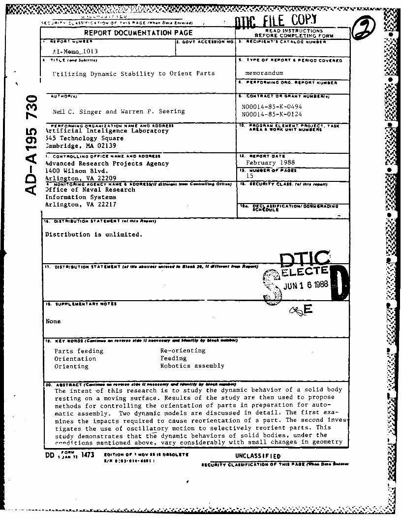
Utilizing Dynamic stability to Orient Parts memorandumSPERFORMING ONG. REPORT MUMOER
o AUTWO"(4J 11. CONTRACT OR GRAN4T NUMUER(aj
Neil C. Singer and Warren P. Seering NOOOI4-85-K-0494NOOO14-85-K-0124
PERFORMING ORGANIZATION NAME ANC ADDRESS 10. PROGRAM ELEMENT. PROJECT, TASKLfl krtificial Inteligence Laboratory ARA& OKUNT.U~R
5' 45 Technology Square '
Vol ambridge, MA 02139 1
SI. CONTROLLING OFFICE NAME AND ADDRESS It. REPORT DATE
kdvanced Research Projects Agency February 19881400 Wilson Blvd. 13 MUNGER Of PAGES00 rlington, VA 22209 15< £MONITORING AGENCY NAME II AOORIESS(1U e.,iifooi Eom Comsetfh,* Ofie*J 1S. SECURITY CLASS. (of (ti ropeff)
)ffice of Naval ResearchInformation SystemsArlington, VA 22217 1$*. OttASF CTO/OONRON
IS. OISTRISUTION STATEMENT (of #hie0 ROPSIj
Distribution is unlimited.
17. DISTRIOUTION STATEMENT (of We. o~oliacI onewed In steek 0 It il.ft.-tba 4400) 3o
( 7ELECTE
16. SUPPLEMENTARY NOTEtS
None N
It. KEY WORDS I'Cenflowe anf owovs Sie #i aeoeosy ON Ide"01l1 by Aleek woobst)
Parts feeding Re-orientingOrientation FeedingOrienting Robotics assembly
20. ANSTRItACT (GeMS..w an foime.el 84 It 4*o mi Ide"110F Or' Week .nbue
The intent of this research is to study the dynamic behavior of a solid bodyresting on a moving surface. Results of the study are then used to proposemethods for controlling the orientation of parts in preparation for auto-matic assembly. Two dynamic models are discussed in detail. The first exa-
tigates the use of oscillatory motion to selectively reorient parts. This
study demonstrates that thi dynamic behaviors of solid bodies, under the
r-nditions mentioned above, vary considerably with small changes in geometryDD 'O"'j 1473 ECTION, air I NOV es is OUSOLaTitNLSSFE
,A 5~~/N1 0102014-6601 INLSSFE
SECURITY CLASSIFICATION OP THIS PAGE (ften Does39m
- . p p . . .. . . *~ * ~ * . -''-p --

Block 20 cont.
or orientation.
4%
64-
% P..
P.
-v N
.%,IASSA('II(SETFTS INSTITFU'TE OF TECHNOLOGYARTIFI(IAL INTELLIGEN. E LABORATORY
A.I.Meino No. 1013 February, 1988
Accession For 7TIs - RA&I_
DTIC T',2"
Unannounced ElUtilizing Dynamic Stability Justioati on.
To Orient Parts
Distribution/Availability Codes
Neil C. Singer Avail and/or- "---!
Warren P. Seering B It Special
Abstract: The intent of this research is to study the dynamic behavior of a
solid body resting on a moving surface. Results of the study are then used to pro-
pose methods for controlling the orientation of parts in preparation for automatic
assembly. Two dynamic models are discussed in detail. The first examines the
impacts required to cause reorientation of a part. The second investigates the use
of oscillatory motion to selectively reorient parts. This study demonstrates that
the dynamic behaviors of solid bodies, under the conditions mentioned above, vary
considerably with small changes in geometry or orientation. .
Acknowledgements: The (iot author was sponsored by the Office of NayvResearch Graduate Fellowship Program. The research described in this paper was :
performed at the Massachusetts Institute of Technology Artificial Intelligence Lab-
oratory. The laboratory's research is funded in part by the Office of Naval Research
under ONR contract N00014-81-K-0494 and in part by the Defense Advanced Re-
search Projects Agency of the I nited States Department of Defense under ONR(onl .ract NO00 II-85- K-O 124.
c 1988 'lassachuscts Institute of Technology.
Irom .Journal of Applied Mechanics, December 1987, Vol. 54, pp. 961-6.
:%
88
1 Introduction and Problem Definition
-,Coriventionally, parts are oriented by bowl feeders. These machines vibrate andthereby convey parts through a series of lilters which reject all but a particular orientation.Rejected parts are returned to storage. Many researchers have examined the implemen-tation of programmable or adjustable filter stages, (Boothroyd, 1975) (Boothroyd and Ifo,1977) (Boothroyd and Murch. 1970) (Boothroyd et al., 1982) (Boothroyd et al. 1977)(Lozano-PNrez, 1986)(Murch, 1977) (Murch and Boothroyd, 1975) (Murch and Poli. 1977)(Redford et al., 1983a) (Redford et al., 19831) (Singer, 1985) (Suzuki and Kohno, 1981).These techniques are often successful for limited classes of parts. The scope of this paperis to present theoretical results which may be useful in feeder designs. It is hoped that amore detailed understanding of the dynamic behavior of bodies resting on a moving surfacewill facilitate the design of new types of programmable parts feedcrs. ,'5 "
.---... . . / , A' f' -K (
2 Impact ileorientation
In this section, we determine the conditions necessary to cause part reorientation. Apart starts in a stable orientation (a natural resting aspect (Boothroyd and Ho. 1977)) on aflat surface. It is then given an initial horizontal velocity after which it impacts a wall nearthe surface upon which it is resting (figure 1). The equations describing the impact arebased on conservation of angular momentum about the impact point. After impact, the
&1- principle of conservation of energy is applied in order to determine whether reorientationoccurs.
The part shown in figure 1 is a cylinder, but the analysis easily generalizes to anyobject. The important parameters are the mass., m of the part; the moment of inertia,1: and the constants, I and h. which locate the center of mass, cm, with respect to theimpact point. The expressions for angular momentum, Li, before and, Lf, after impactare (Klepner and Kolenkow, 1973):
1, rn V, h
Lf I, Vf (2.1)
SVh2 . 12
r,,r , s the speed of the center of nass prior to impact, Vf is its speed just after impact,and I,,. the inertia about tee impact point, is defined as
l. l, (h2 / 2)M
with I,. the inertia a, w I), ,. r . i ; ,ti energy just atter impact tothe change in polential energy which will cause the part to reorient yields
2j., -. "-1 r-g [(h - - h (2.2)2 1?2 !
Solving equations 2.1 for Vf, substituting int,)equation 2.2, and then solving the result,for the critical value of Vi yields
(2, ,2 1L/ -2 [ (h / (/)
which is an equation for the minimum initial horizontal velocity that will cause reorienta-tion. For cylinders, L. is ' + 12; for rectangular parts, L, is ,1(t- 12).
In order to test the ability of impact reorientation to discriminate among differentorientations, it is useful to consider a part which has two very similar orientations. Figure2a shows a rectangular solid part in two possible orientations. One edge is bb longerthan the other where - is expressed as a fraction less than one. As the part exchangesorientations, the center of mass location changes in both height and horizontal distancefrom the impact point by 6. The ratio of V-rn of orientations one and two (denoted by 'Iand V2) expanded in a power series in 6 is expressed as:
I *Jq
-I -+ 2.26 - 1.33b - (2.A)V1 J.
This equation illustrates that small differences in location of the center of mass result in-significant variations in impact reorientation velocity.
To verify the equations and to( get a measure of experimental error. tests were per-formed. Cylinders of different size were placed on a moving conveyor belt. The cylindersimpacted a steel wall .889 mrnm (.035 inch) high. Fifteen trials were made for each velocityset point and the number of pegs which reoriented was counted. The velocity of the beltwas monitored by a tachometer which was friction driven directly by the belt.
Several tests were performed. First, the lower threshold velocity, Vf 1 , was determinedby finding the maximum velocity at which no pegs fell over in fifteen trials. The upperthreshold velocity, Vfa11 , was determined similarly by finding the lowest velocity at whichall pegs fell over. The median velocity V ,j is simply the center of the velocity banddefined by 17- and Vfll. Finally, two percentages have been determined from this data.The percentage of error is calculated between the theoretical velocity, I"Try, and themedian experimental velocity, Vte,. The uncertainty band of the experiment is calculated 0,from V--- and Vj,,n; this band is represented as a percentage of v',,j.
R vulIts confirm that the system nio(lel adequately represents the experimental situ-ation. All tests performed had narrow uncertainty bands. This indicates that there is asharp cutoff between not having enough energy to cause reorientation and having enoughenergy to guarantee reorientation. In addit ion, the error percentages between V-rh,. , and
i .,. smill. Fur hermnorc, tIke scaiig ot the velocity agrees with the scaling predicted "-in equation 2.-3 Two pegs which vary greatly in size arid length to diameter ratio can havethe same reorientation "elocity. Table I gives typical results for two different cylinders.
The abilitv to discriminate between orientations, or to reorient one object while notreorienting another, depends heavily on the quality of the velocity source. Fortinately.
r . . -2
excellent velocity sources are inexpensive and easy to build. Figure 2b presents a velocityline with the reorientation velocities for the two parts shown in figure 2a. The dark sectionof the line identifies the desired operating velocity range. Within this range part 1 willalways be reoriented, while part 2 will never be reoriented. By cascading several of theseimpacts at different, velocities, a set of like parts, initially oriented randomly can all bedriven to the saine orientation.
3 Vibratory Reorientation
3.1 ModelingThe model for this section is an object in a gravity field. The table on which the
object rests oscillates vertically (Figure 3). The object is first given some initial angle, 0,).possibly by a sudden motion of the table. For a proper choice of X(t), the table drivingfunction, the given object can be maintained in a rocking mode of fixed amplitude. Thedriving function of the table can then be changed, causing an increase in the amplitude atwhich the object will continue rocking. Finally, the amplitude can be increased until theobject reorients.
Because of the discontinuity of motion as the part impacts the table. the solution tothe equations governing the system must be broken into regions. First. the region in whichthere is no impact will be examined. The equations of this motion may be generated using
*-, Lagrange's method. The potential energy function can be expressed as
V rmg(rsinep+ x) , (3.1)
where V is the potential energy, 7n is the part mass, r is the distance from the contactpoint to the center of mass., 0 is the angle between the horizontal and the vector r, and xis the vertical position of the table. The kinetic coenergy can be expressed as:
1 d& 2 [dx dO 1 m 1 F 1xc - - - -r-- -cos - - r-sink , (3.2)
2 ~dt 2 [dt dt 2 [dt Jwhere 1, is the moment of inertia of the part about the center of mass. These two termscan be used to form the Lagrangian which is then substituted into Lagrange's equation,yielding the two equations of motion for the system,
. n 2 d2 -mr cos¢ g + d 2X 0(x dr2) dot2 (3.3)
ft mr- cos - mr- sin 0 -mg = Fdt2 t dt
The first of the equations gives the basic inotion of the object, while the second equationis an expression for F, the contact force. These equations are valid in the conservative
regions without impact.
,' !1
The next step in formulating the model is to represent the impact of a part with thetable. At impact, the center of mass of the object has a vertical velocity which is reflectedwith a coefficient of restitution, c. In a perfectly elastic impact, ( is equal to one. Physical -
experiments were performed to determine the coefficient of restitution for aluminum partsrocking on an aluminum plate. The coefficient of restitution was determined to be betwee'n.7 mnd .75 for these tests. For all of the simulations in this paper, an c of .5 was used tobe conservative.
As a part hits the table, the impact will also affect the horizontal velocity. If the tableis frictionless, the part will slide. In this derivation the table was assumed to be roughenough so that the contact surface will not slide on the table and after impact the partwill continue to rock by rotating about the new contact point.
The next step in creating steady rocking motion was to determine table accelerationprofiles which would cause a part to oscillate at fixed amplitude. The amplitude of vibrationis coupled with the frequency of oscillation. As the part gains energy, both the amplitudeand the period of oscillation become greater. This response makes analysis difficult: fewtools are available for predicting the behavior of this type of system (Meirovitch, 1975).
An analytical solution to the system equations for the time required for passage froman initial to a final angle can be derived for the case in which the driving function, L+
remains constant. The derivation of this solution is based on conservation of energy inthe region without impact. For a constant table acceleration, the part can be consideredto be in a conservative field as shown in equation 3.3a. In this particular case the energybalance equation becomes
I (- m(g + -2)r sin 4.
2 d 2 d2x .
- (Ic mr) ! M(g -- t2 )rsirip , (3.si)
wheie 6 is the starting angle of the object, and 0 is some angle of interest. Note that thederivative of this expression is the result obtained in equation 3.3a. Equation 3.A can besolved for '10
cit
dO /2m(g - )L , r mr 2) d, 2
'U2 d 2
d( = ± m+-si\n (( - sine5 (3.5)dt , + Vrn r 2rng -a ,r .
This equation can in turn he sol ed by separation of variables and then once integrat-ing with respect to time. For convenience the constant A is defined as
A (V, t- rnr 2 2),10.A s1 2'in o , (3.6) I'
2rn(g + ) r
and the result is _ _
d6- +--)rdt (:.7) -
, / -sine I 1. 6 mr 2
? •1
-C,
w here a, is t he endJing angle of' interest Ti'lie righit side is a simiple ii erlthe Itk side is anelliptic integral. 'Ihel solution tI h is eq tat ion will be presented as a cotlblinaltiof of' ellipt i(*fi tict ionlS. Thllough el ip)titc finctions ca ntiirot be ex pressed in t ermrs oF elemnenta tr y funictions.hey are well iinderstonod an rid a N iesily% computed. Int order to show t hat equat ion 3.7 p
lbecOTTIVIe ar elliptic liitegraI. ia luange of vairiahles, must. be mtade. Let
so I (3.8
-iii 0 Cos if, . (3.9)
Mnd
(c0 o0106 sinl wdw (. 0
FromT theSe We get
sinl i.dw
\ coS 2 i1'
Sst itiirgequat ions :3.11 arnd 3.8 into the left. hand side of equiation 3.7 produces thefollowi rg expressionl
do ~ ~ ~A dw(3.12)
* In the cwse of i nijact
whlere 0~ is deffined as the angle between thle bottom of the part and the vector r fromthe Contact poin ito the (Center of' ma~ss. If' Owh integral is then rewritten as two integralsstart irig frorri zero, equation :3. 12 canr be (x presse1 in terms of the elliptic integral of thefirst, kind (Gradshteyu arid fRyzik, 1980):
dw
v, Cos itW Co 11
J 2('(x 1, k) I"(x,kr)I A < 1I3.3
([,'((x:,, k2 ) Fix.1, k2 )) A (313
The elliptic in tegraId of' thie fi rst. kind expressed in normral trigonometric form is
\ I Ak2sill
5'. p .
and the limits are
I si n 0,2 \ 1
0(1 /.
• 2 10', 'T
X 4 --2 1
k2
~ *Ain terms of the system parameters.
3.2 Choice of Driving Function
As mentioned previously, this analysis is correct only for constant values of Thefirst driving function to be considered was a periodic rectangular wave in acceleration (fig-ure 4). Four parameters must be selected to fully specify the waveform the accelerationupward, AXI; the acceleration downward. AX2: and the switch times. TI and T2. Theselection of these parameters is constrained by several relations. First, the areas A J andA2 must be equal in order for the table to return to its initial position and velocity aftereach cycle. Second, the part must start, and finish the cycle at the same angle (the sta-bility requirement). Lastly, the acceleration downward must never excee(l gravity. Thisconstraint is set so that the part does not lose con tact, with tile table.
Equations 3.13 and 3.15 were substituted into a nonlinear solution prograin whichcalculated accelerations and switch tirnes that brought, a chosen part back to its initialangle in exactly one cycle. Figure 5 shows a tine history of the acceleration of the table,12-, and of the angle 0 as determined by numerical simulation of equation 3.3 including the
model for impact. For this case, the rocking motion is stable. However, small parametervariations cause an instability. Figure 6 shows the rocking motion for an object given aslightly larger initial amplitude than that of figure 5. After the first impact, the peakamplitude is too low; after the second, it is too high. Eventually, the phasing betweeninput and output is lost and the part ceases to rock.
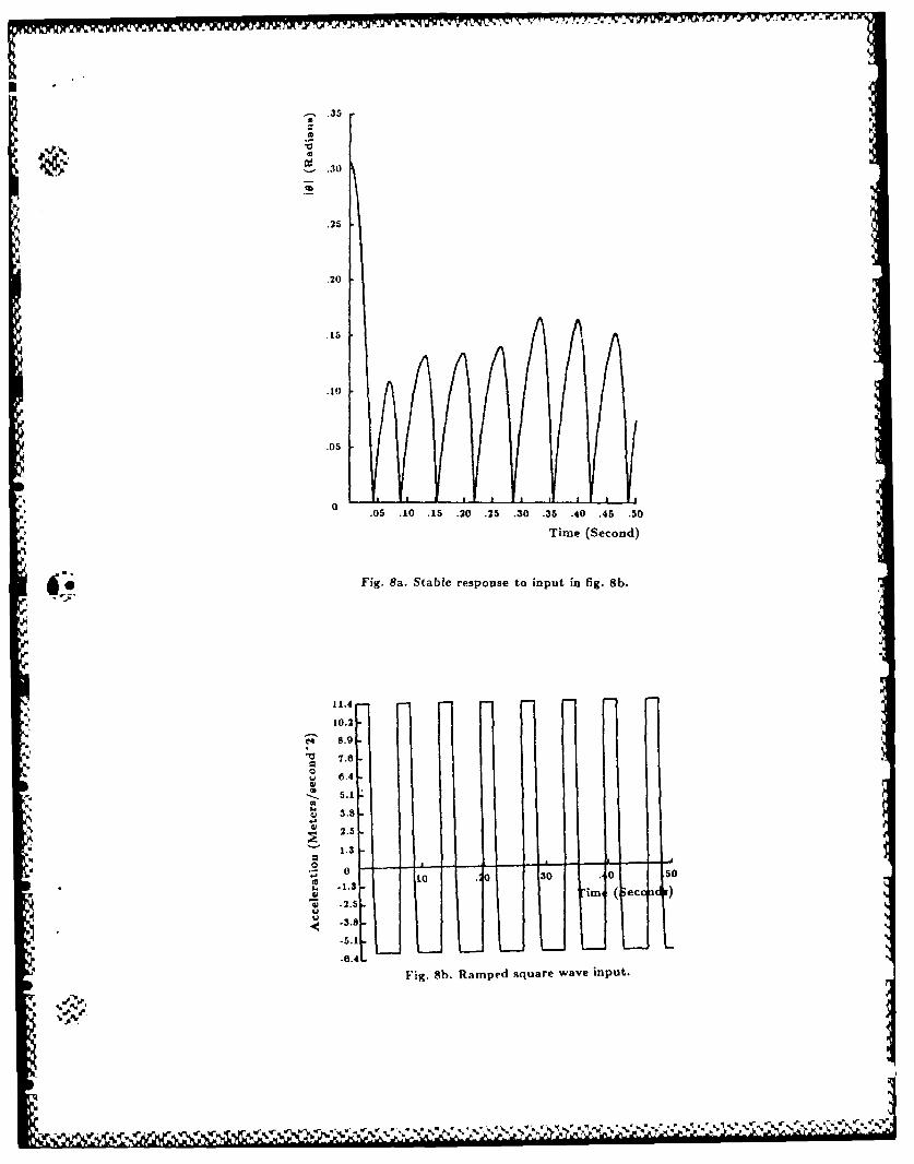
Because our goal is to bring parts to a stable rocking motion from a range of ini-tial conditions. the rectangular acceleration waveform will not do the job. A varietv ofwaveforms were tested. One which exhibited good performance is shown in figure 7. Thewaveform is simply the rectangular waveforrn with t lie edges sloped. Figure 8 shows results
from a numerical simulation using this forcing function as input. A part is started withan initial angle which is twice the steady state angle Yet it still reaches a stable equilb-,riumn motion. This suggests that, by using the proper waveform, a great range of initialconditions of the part can be tolerated.
6
d V.PV V V? I~ *~~' ~ .V - t-V-I'
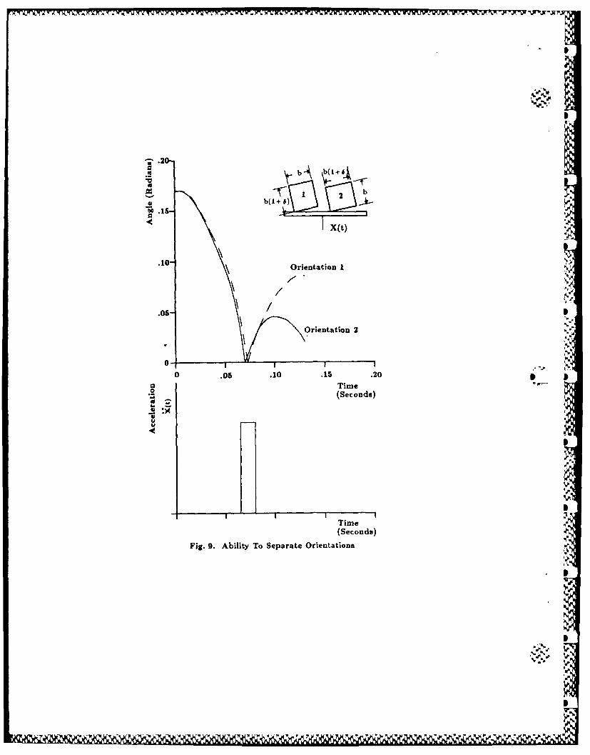
If hils ret hod is to be used to s(Cc tiye lv reorienit parts, dIifferen t 1)arts s honl e x hibhitsignific ant Ilv different res porises. F iglre 9 shbows vaitr IatIi iii res ponse for t xv( s ItiiIa r pa rtsgivern the same in itinal a ugle and( subl'ecltedi to the sarne acceleration profile. For Iessin iilat ions. upwardi accelerat ion vas set tC o ccuiir around1( t lhe I i trie of' imipact . Several
simu~ilat ions were execunte (1withi various leii-t w inW dows" of uipwa rd accelerailon. Theal)[ilt 'v to dIiscriiinate degraded as tOle wvintd~ow b~ecamre very large iii comnpa rion wvith the(differenlce in imtpact hies.
An att emnpt was mradle to design anl ex pen rimental apparat us for st udy of tbe behaviordIesc ri bed above. No) sat isfactIory configu rat ion coul1( be created at a reasonable cost . Tod1rive reasonably Inarge parts wvit h periods of'oscillation greater t hain .5 secondls wonId reqirea table xv tb a range, of mltion su bstaritinaIly greater thban that of available cdec tromnag net iCshakers. Hydraulic shakers are (lesignedi toC delixer large forces and have servo~ valves v i ic hare to() small to supply the floxv rates necessary to achieve the required ve~dwit es. Thel(idleal drii rig syst er Would( be a siniaI IdCiami et er bydranillic actunator) wit h a relatively largeservo) valve.
4 Conclusion
ibis studyV of part, rMitiCor has ClerllSt rated that. smrall variat ions in iniertial properties* ~fromn one( part to anot her onause sign ific ant differences in the dy namic behavior Cof t he twvo
* ~parts. Txwo example t ecn niques wvnich calpitiitize on t is property were presenltedl. Practicalimplementation of the first technique. impact reorientation. is feasible given current design4. i~lchnolng\.'. T'he SecondC tech niqtue. v ibratory reCorient at ion, willI require construction of
Cisc i lat In,, talesvi wt h perfonriiance chiaracterist ics available Cofl thbrough custoni des igni.
5 R eferences
Boot hrovd, G.. 1975, -Autorriat ic Hlandiling Cof Smrall Parts," Annals of the Interna-t ioi ial Inst ituite for Producwtion Engineering Research (Annl CIRP). Vol. 24.No. I . pp. 393-398.
Boo0th rovdl, G. and 11o, C.. 1977, '"Natural Resting Aspects Cof Parts for Automatic [Ian-dling," Transactions of the ASME. May. pp. 314-317.
B~oot hi roy d. G.. and MTutrchi. 1-1I'- 1970. "Performance of an Orientinug D~evice Emnployed inVib~ratory Bowl Feeders," Transactions of the ASME. August. pp. 694-698.
Booth l rC 'vd , Geoffrey: Poli. C'orrado: and Xl iirch . Laurence E., 1982. A utomatlic Assembly.Marcel Dek ker. [tic. New Yonrk.
[loot IiroW~. G.: P~oll. (XI?.: and XI irch, L.E1', 1977, "Handbook Of Feeding and OrientingTech iiiqiies fCor SmtrallI Part s.- Aiut omt0on IProjec t Department of Mec harnic al Kiigi-tiieenmg. 1*niversity of' Nassachuisettis, Amnherst. Ma.
( iiik li t c'~ , I.S.: I?vzli i k. 1. M.. los'O, (11)1: of (in'fc/ralls, Serz'es, anud I-rodiocts. AcademicP ress1 -N ew York. pplGO-16-1.
7 , - 5 ' 5* . ~ . % ,5' ~ % s % ~ ,'.- % .55
Klepner, Daniel; Kolenkow, Robert .J. 1973, l1it hInrodtielon, (o Alcchamrics Mc ( raw-1 I HB~ook Co., New York.
Lozano-P6rez, Tomis, 1986, "'Motion P Ia rr n iig itid tire designi of ( Orirri ng I )ex cv 1(rVibratory Parts Feeders."To be published ini IEEE .1oiirnal Of Robotics AridAuitoination. mIT A[ Laborator.
Meirov itch, Leonard, 1975, Elements of . ibrobri Anra/ysis. \1cGrav-Illill, hic, New York.
Murch, Laurence E., 1977, "Feeding anid Orienting Parts Automatically." SME TechniicalPaper, AD77-707.
* Murch, L.E., and Boo'hroyd, G., 1975. "Feedinrg Smrall Parts for Assemnbly.* ArriericariMachinist. October, pp. 106-110.
* ~Murch. L. E.. and Poli, C., 1977, "A nalysis of Vve ding arrd Orienting SN"StenS for Aut orna IAssembly. Part 2," Transactions of the ASME. May. pp. 308-313.
Redford. A. H.; Lo, E. K.: arid Killeen, P., 1983 . -Parts Feeder for A fuit i-Arni Asserri-bly Robot." Department of Aeronauticail anrid Mechanical Engineering. University ofSafford, U.K., (unpublished copy of' a manuscript presented at the 15th CIRP Inter-national Seminar on Manufacturing SYs terns, Amherst. Mlass. June 1983)
Redford, A. H.; Lo, E. K.; and Killeen. P.. 198Th, "Parts Presentation To A Mrt-riAssembly Robots." Department of Aeronautical arid Mechanical Ingineering. 1' ni-versi ty of Salford, U.K., (uinpublished copy of' a irnursc ript i lblislred ill r.he (,'If?[PAnnals Vol. 32, 1. Presented at the (:11? P eneral Assemnbly. Hlarrogate. Augut-I
Singer, Neil, 1985, "~Utilizing Dynamnic Awlu Static StabilitY v o Orient Parts." S)V1 Thiesis,Massachusetts Institute of Tfechnology.
Suzuki, T. and Kohno, M., 1981. "'The Flexible Parts FeedIer Whicir Helps A* Robot As-sernible Automatically.- Asserilbly Airorriatioti. IFebrrrary%. pp. 86-92.
- ~ ~ X 7.F 1j-v -v 7-V - .- -*
r
Fig. 1. Impact reorientation model.
b~b(1+6)
Fig. 2 a. Two similar parta.
V- v v V V V Vfall med fall Fall- med fall
0 2 2
Fig. 2b. Distinguishing the parts in Fig. 2a.
~ S ~ .,* S~* ~5 - 5 ~ ~j~5,' ~ ~~~S *~ *%
-T-1 -WK? Xi 'Mr
IMoment of Inertia
Mf Mass
r
#~19
Fig. S. Vibratory reorientation model
0 2
A d Transition Point
* AXI
Al
A 2
d AX2
-t Fig. 4. Square wave acceleration input. *~
0.18. desired level
S0.16
0.14
0.12
0.10
0.08
0.06
a? 0.04
0.02
0.0 0.2 0.4 0.6 0.8 1.0 12 1.4 1.6 1.8 2.0Time (seconds)
Fig. 5a. Response of a part to input in rig 5b.
S0.20
.. 0.15
.~0.0
0.00
.2] .2 6 08 .0 1 14 6 1 2.0
05 rme (se ds)
-0.10
Fig. 5b. Square wave input.
S0.25
41 0.20
desired level
0.15
0.10
0.05
0.0%1 z2 0.4 0.6 0.1 1.0 1.2 1.4 1.6 IT1 -- 2.0
Time (seconds)
Fig. 6. Unstable response for a part starting 6% above the desired level.
AXI
0
-AX2
Ti TZ TZ4
I..Fig.7. Rmpedsqure wve iput
.1----. , ,- --
0
,. .30
.25
.20
.15
.10
.05
.05 .10 .15 .20 .25 .30 .35 .40 .45 .50
Time (Second)
Fig. Sa. Stabie response to input in fig. 8b.
,!
11.4
10.2
e 8.9
" 6.4
*-. 5.1
e 3.82.5
0
-1.3
m4 (eco a. 2.5.
-3.8-
-5.1L L-6 .4 '
Fig. 8b. Ramped square wave input.
--rv5~ * .* ~ * ~.WW'\I ~ * *~
b(, 6)\brb
< ~x(t)'
.10" \ Orientation I
.05-
Orientation 2
0 .05 .10 .15 .20-
~TimeOrett(Seconds)
Time
(Seconds)a... az.
.~ :x
Fi.9 blt oSeaaeOinain
Timee

5 I I 3
.~ -~
S
S
AI.~ -,~- :~
a SN ~' .,
______ I0
A.KiiMU
(.1/0
Iiv~.
Sp1-icwww