leading practices to reduce the possibility of a natural ... · the purpose of this documentis to...
TRANSCRIPT

Leading Practices to Reduce the Possibility of a Natural Gas Over-Pressurization Event
November 26, 2018

1
DISCLAIMER
The American Gas Association’s (AGA) Operations and Engineering Section provides a forum for industry experts to bring their collective knowledge together to continuously improve in the areas of operating, engineering and technology when producing, gathering, transporting, storing, distributing, measuring and utilizing natural gas. AGA publications such as this provide for the exchange of information within the natural gas industry and scientific, trade and governmental organizations. Many AGA publications are prepared or sponsored by an AGA Operations and Engineering Section technical committee. While AGA may administer the process, neither AGA nor the technical committee independently tests, evaluates or verifies the accuracy of any information or the soundness of any judgments contained therein. AGA disclaims liability for any personal injury, property or other damages of any nature whatsoever, whether special, indirect, consequential or compensatory, directly or indirectly resulting from the publication, use of or reliance on AGA publications. AGA makes no guaranty or warranty as to the accuracy and completeness of any information published therein. The information contained therein is provided on an “as is” basis and AGA makes no representations or warranties including any expressed or implied warranty of merchantability or fitness for a particular purpose. In issuing and making this document available, AGA is not undertaking to render professional or other services for or on behalf of any person or entity. Nor is AGA undertaking to perform any duty owed by any person or entity to someone else. Anyone using this document should rely on their own independent judgment or, as appropriate, seek advice of a competent professional in determining the exercise of reasonable care in any given circumstances. AGA has no power, nor does it undertake, to police or enforce compliance with the contents of this document. Nor does AGA list, certify, test or inspect products, designs or installations for compliance with this document. Any certification or other statement of compliance is solely the responsibility of the certifier or maker of the statement. AGA does not take any position with respect to the validity of any patent rights asserted in connection with any items that are mentioned in or are the subject of AGA publications, and AGA disclaims liability for the infringement of any patent resulting from the use of or reliance on its publications. Users of these publications are expressly advised that determination of the validity of any such patent rights, and the risk of infringement of such rights, is entirely their own responsibility. Users of this publication should consult applicable federal, state and local laws and regulations. AGA does not, through its publications intend to urge action that is not in compliance with applicable laws, and its publications may not be construed as doing so. Changes to this document may become necessary from time to time. If changes are believed appropriate by any person or entity, such suggested changes should be communicated to AGA in writing and sent to: Operations & Engineering Section, American Gas Association, 400 North Capitol Street, NW, 4th Floor, Washington, DC 20001, U.S.A. Suggested changes must include: contact information, including name, address and any corporate affiliation; full name of the document; suggested revisions to the text of the document; the rationale for the suggested revisions; and permission to use the suggested revisions in an amended publication of the document. Copyright © 2018, American Gas Association, All Rights Reserved
2
The purpose of this document is to provide guidance to natural gas utilities on leading practices that may supplement current practices to reduce the possibility of an over-pressurization event, especially in a utilization pressure system. AGA’s member companies are steadfastly dedicated to the continued delivery of natural gas in a safe and reliable fashion to the communities they serve. We are committed to sharing leading practices and lessons learned across our industry in order to enhance our collective performance. Many of the leading practices described in this document are currently implemented at natural gas utilities but they are not uniformly applicable to all systems nor exclusive. This document contains practices above and beyond minimum federal regulations. Depending on each system’s unique characteristics, it is the consensus of AGA members that appropriate implementation of the practices in this document may reduce the possibility of overpressurization. The determination of whether to adopt any of the items contained in this technical note is individual to each company, recognizing that not all practices will be applicable given the size, configuration, pressures, and other features of a particular system. The need to implement every practice and the timing of any implementation of the practices described in this document will vary with each natural gas utility and the specific environment in which they operate. The actions within this document should be evaluated in light of each operator’s system, geographic variables, the operator’s independent integrity assessment, risk analysis and mitigation strategy and what has been deemed reasonable and prudent by their state regulators. Therefore, not all of the practices described in this document will be applicable to all operators. As used herein, the term “should” is not mandatory but is to be acted upon as appropriate. This document is intended to serve as a technical resource for natural gas operators. Note that the appendix is an excerpt from an AGA publication which contains additional background information and practices which address overpressure protection and the related topic of system regulation. Since the scope of this document is limited and primarily focused on practices to further reduce the possibility of an over-pressurization event, it does not identify leading practices in other areas, including emergency response. The reader should not conclude that the AGA members believe these are unimportant issues.

3
.
Contents Section 1: Design of Distribution Systems and Regulator Stations ............................................................... 4
Background of Natural Gas Systems ......................................................................................................... 4
Design Practices For all Pressure Classifications ....................................................................................... 6
Additional Design Practices for Utilization Pressure (i.e. low pressure “LP”) Systems............................. 9
Section 2: Operating Procedures and Practices .......................................................................................... 10
Regular maintenance for regulator stations ........................................................................................... 10
System Monitoring .................................................................................................................................. 10
Records ................................................................................................................................................... 11
Damage Prevention ................................................................................................................................ 11
Construction and Work Permitting Process ............................................................................................ 11
Tie-ins and Uprates ................................................................................................................................. 11
Standard Operations and Maintenance Practices .................................................................................. 12
Construction, Tie-Ins, Tapping, Uprates, and Abandonments Practices ................................................ 14
Damage Prevention Practices ................................................................................................................. 15
Records Practices .................................................................................................................................... 16
Section 3: Human Factors .......................................................................................................................... 18
Management of Change (MOC) .............................................................................................................. 18
Training for Prevention and Recognition of Abnormal Operating Conditions ....................................... 18
Operator Qualification ............................................................................................................................ 19
Field Oversight ........................................................................................................................................ 19
Management of Change (MOC) Practices ............................................................................................... 20
Training for Prevention and Recognition of AOCs Practices ................................................................... 21
Field Oversight Practices ......................................................................................................................... 21
Section 4: Managing the Risk of an Over-pressurization Event .................................................................. 23
Distribution Integrity Management ........................................................................................................ 23
Support from stakeholders, communities, and customers .................................................................... 24
General Practices .................................................................................................................................... 24
Industry practices specific to DIMP: ....................................................................................................... 25
Glossary ....................................................................................................................................................... 26

4
Section 1: Design of Distribution Systems and Regulator Stations Background of Natural Gas Systems Natural gas utilities provide service to residential, commercial, and industrial customers. The typical source of the utility’s gas supply comes from pipelines that operate at a high pressure. The high elevated pressure allows the gas supply to travel many miles underground throughout the country. For delivery to residential, commercial, and industrial customers, the pressure must be reduced to a lower pressure level that the customer can receive. The gas industry has used pressure regulators to reduce pressure since the 1800s. The primary function of a pressure regulator is to maintain constant, reduced pressure at the outlet. This is accomplished by varying the regulator’s position/opening such that the flow of gas through the regulator station matches the demand on the downstream system. As system demand decreases, the flow through the regulator decreases as the regulator responds to the increase in pressure in the system. Conversely, as system demand increases, the regulator flow must also increase (otherwise the system may run out of supply). The types of gas regulators available for selection by the gas industry range in size depending on the system demand being supplied. Despite their diverse sizes, they can be categorized according to application: appliance, service, industrial, and distribution/transmission systems. Just as there are many regulator choices there are also multiple points where regulators are used for pressure reduction. Common design points include city gate stations, district regulator stations, farm taps, industrial customers and residential customers. City gate stations are a primary pressure reduction point for the high-pressure pipelines that transfer gas to distribution systems. The basic function of these stations is to link high-pressure transmission pipelines to distribution pipe systems. A city gate station usually performs three primary functions:
1. It reduces the pipeline pressure to operating pressure of the utility pipe system. 2. It measures the volume of gas delivered to the utility. 3. Odorant is added to the natural gas to enable the detection of gas.
District regulator (DR) stations are pressure-reducing facilities downstream of city gate stations that reduce the pressure in the pipeline coming from the city gate to a lower pressure. This lower pressure downstream of a DR is more suitable for providing service to customers or other distribution networks within the LDC’s distribution system. The operating pressure of the distribution systems upstream of district regulator stations vary depending on the distribution systems configuration and downstream demands. The pressure of the distribution systems downstream of these DR stations usually vary from about 100 pounds per square inch gauge (psig) to as low as 0.25 psig. These downstream pressures may be categorized as high, medium, or low-pressure distribution networks. Although classification of pipe networks by pressure level is common, terminology and the pressure range covered by each class varies between utility operators and systems. System pressures are affected by a service area’s demand with respect

5
to customer usage needs, weather considerations, design loads, and other maintenance requirements. High pressure networks offer service to residential customers either directly or by means of a medium or low-pressure distribution networks. Whenever gas is fed from a network operated at a higher pressure to one operated at a lower pressure, a pressure regulator is installed between the two points. A pressure regulator will reduce the higher pressure of incoming gas to lower pressure of outgoing gas. The design criteria for each system are unique, leading to different designs for each regulator station. Some examples of factors that cause variations in regulator station design include:
• Maximum and minimum flow requirements based on the customers demand • Upstream and downstream maximum allowable operating pressure (MAOP) • Forecasted future flow requirements • Maximum and minimum pressures available from the upstream system • Number of stages for pressure reduction • Number of supply inputs - fed by single or multiple supply lines • Gas temperature and gas quality • Location and environmental conditions, driven by local ordinances • Amount of land or area available for the station to be built • Gas contaminants (such as sulfur, liquids and particulate debris) • Proximity to highly populated areas
Station design aspects that vary include:
• Type of regulator(s) or control valves installed • Above Ground versus Below Ground • The quantity of regulators installed • Location of downstream pressure sensing points • Type of over-pressure protection installed • Use of heaters • Equipment to remove contaminants from the gas stream • Equipment to allow remote control of pressure settings • Use of odorizers
Distribution systems are designed to provide safe, efficient, and reliable service to the customer. Customer fuel lines operate at low pressure to ensure proper appliance performance, typically less than 1 psig. A lower pressure system that delivers gas at minimum delivery pressure is sometimes referred to as a utilization pressure system. Consequently, it is not necessary to install a service regulator to reduce pressure for each customer when the system operates at utilization pressure. Operating a system designed for minimum delivery pressure can be challenging as the needs of the system are dynamic and change with demand. Extreme cold weather days, customer

6
demand changes, etc. require accurate pressure control. Utilization pressure systems have typically been designed as fully looped systems. Fully looped systems minimized customer outages by providing many alternative paths by which gas could reach the customer. When a distribution system is designed at pressures higher than utilization, i.e., above the customers delivery pressure, service regulators are installed at the customer meter set to reduce and control the pressure to a uniform level to the customer. The modern gas regulator is a highly reliable device; however, failures could potentially occur due to a number of reasons such as physical damage, equipment malfunction, and the presence of foreign material in the gas stream. The industry has developed multiple layers of protection to mitigate the potential of over-pressurization. While there is no design standard that is applicable to all situations, some common over-pressure protection designs include:
• Use of in-line monitor regulators that control pressure upon failure of the primary control regulator.
• Use of relief devices that vent excess gas pressure to the atmosphere. • Use of automatic-shutoff devices, such as positive shut off valves and fail close regulators
to interrupt the supply of gas. • Installation of filters and strainers to eliminate debris entering a regulator. • Deployment of signaling devices that notify operating personnel of equipment failure or
abnormal operating conditions (AOCs). • Use of telemetry and transducers that are monitored remotely with corresponding alarm
set points. Customers on systems that operate at pressures higher than utilization system pressures have their own individual regulator located at the meter. Customers served from utilization systems do not require individual over-pressure protection because the entire distribution system operating at utilization pressure has over-pressure protection at the district regulator station or at another location. The basics of over-pressure protection requires the design to protect the downstream piping system from excessive pressure. Design Practices For all Pressure Classifications The following practices should be considered when designing new regulator stations, modifying existing stations, or selecting over-pressure protection. System, environmental, and other factors unique to each operator will determine the applicability of each practice: 1. Practice: Include pressure monitoring and alarm functionality within designs of systems and
formalize approval via a Management of Change (MOC) process. Description: Design for a mechanism to generate an alarm condition. Mechanisms may include: alarm relief (“whistle”, “tattle-tale”, “token”), full relief valves, pressure recording devices, pressure signals to Gas Control, etc. Critical pressure points should be capable of alarming or generating a real time notification (relief, whistle, token alarm to Gas Control or Operations, etc.) when an AOC occurs. Safety sensitive pressure monitoring points should be

7
field verified via the communications network to Gas Control. Field equipment should be calibrated and inspected to confirm alarm set points are properly configured to trigger at the appropriate upper and lower limits. Consider any modifications to critical regulators, pressure monitoring points and overpressure devices be validated through a formal MOC process.
2. Practice: Design stations with remotely controlled valves and regulators. Description: When designing new systems consider remotely controlled valves and regulators which may aid in the quick isolation of critical stations, where appropriate.
3. Design for Response Time. Description: When using monitor control valves and slam shut valves, recognize the inherent time to respond/time to close to enable adequate response. Equipment set points and operational characteristics should be taken into consideration.
4. Practice: Size over-pressure equipment to current load and monitor for future load needs.
Description: Primary regulators, monitor regulators and relief valves must be sized and designed to enable adequate over-pressure protection. Parameters which dictate proper sizing, such as system demand requirements, must be evaluated. All station equipment must be designed to operate within its intended operating range. Periodically contact industrial customers to verify gas usage to understand if load patterns have changed, or if a significant change to their future load profile is anticipated. In completing this practice, operators should confirm system equipment is sized appropriately to deliver load and gas pressure safely.
5. Practice: Design sensing lines to be protected and located close to or inside the regulator
station. Description: Sensing lines should be sized appropriately for the regulator and account for restrictions (i.e., reduced port ball valves, needle valves). Each regulator and relief valve shall have an individual sensing line, per 49 CFR Part 192 regulations. Sensing line taps should be located within the station side of isolation valves, and as close to the station as possible. If underground, route the sensing lines for supply regulators and over pressure protective devices to different locations to minimize the possibility of multiple lines being damaged by an excavation.
6. Practice: Mitigate the possibility that a common mode of failure, or a single event, could take out the primary (“worker”) and the monitor regulators. Description: Single events can impact the primary and backup regulator. Determine what can be done to reduce the possibility that any single event can disrupt both regulators.
7. Practice: Install slam shut valves, where practicable Description: Installing slam shut valves is an option for over-pressure protection and loss of sensing pressure and maybe effective for additional system protection. Slam shut valves may be considered, particularly in systems where multiple regulator stations supply gas to an area.
8
8. Practice: Create standard regulator station design templates that are approved by a licensed professional engineer or engineer with equivalent experience and technical knowledge. Description: Establish standard designs for regulator stations. Require that any deviation from the standard should be approved through a design management of change (MOC) process that has been reviewed and approved by a licensed, professional engineer (PE) or engineer with equivalent experience and technical knowledge.
9. Practice: Add or improve remote controls of stations and valves.
Description: Consider designing critical systems, including regulator stations, to be monitored and controlled remotely, or by a Gas Control room via a SCADA system.
10. Practice: Design for atmospheric vent lines to be unobstructed for proper venting. Description: In cases where vent lines are designed with below ground regulators, separate lines should be installed for each piece of control equipment and terminate so they are not impacted by water infiltration into the vault. Above ground facilities should be vented to avoid the impact of insects, ice, and environmental forces. Confirm that all vent lines are secured from motion or vibration.
11. Practice: Above ground regulator sets and other critical regulator station equipment should be protected from vehicular and pedestrian damage. Description: Bollards should be properly sized and installed to protect regulators from any potential vehicular traffic. Other considerations for protection include: locked fences around regulator stations, locked bypass valves, weather protection, and added protection for control lines from damage.
12. Practice: Design for station security. Description: Critical station valves should be designed with locking devices, as needed, so they can be locked in their normal operating position.
13. Practice: Design bypass valve configurations for secure operation at stations.
Description: Two bypass valves should be considered in series to enable quick control if one valve fails during operation. To prevent unintentional operation, locking mechanisms should be installed on the valves when not in use. Consider locating bypass valves at a distance from operating equipment to confirm safe accessibility and operability in an abnormal operating condition, i.e. Fire Scenarios.
14. Practice: Enhance regulator station design requirements in areas with a history of
contaminants in the gas stream. Description: Contaminants can impact pressure regulation equipment operation. Consider installation of a properly sized separator to remove rust, dust, liquids, or debris upstream of the regulator station. Consider installing heaters to reduce potential for freeze-ups and sulfur filters on pilot-operated regulation equipment in areas with known sulfur issues.

9
15. Practice: Confirm flow path to relief valves are not compromised. Description: Steps should be taken to not compromise the flow path to a system relief valve during construction (abandonments, new construction, reconfigurations, and renewals).
16. Practice: Emerging technologies are monitored by the industry and should be considered in future over-pressure designs. Description: When technology develops operators should consider, where feasible, to integrate new technologies that may enhance over-pressure protection.
Additional Design Practices for Utilization Pressure (i.e. low pressure “LP”) Systems In addition to the above, the following practices are options for operators to consider implementing, depending on the uniqueness of their LP system and the local environment.
1. Practice: Design additional over-pressure protection on utilization pressure systems, where
feasible. Description: Consider adding additional layer(s) of protection for over-pressure protection. Design could include an operator, monitor, slam shut, full capacity relief valve, or a customer service regulator, where feasible.
Consider utilizing relief devices throughout the system, particularly in a utilization pressure system fed exclusively by primary/monitor stations. This is an additional control to mitigate the potential for over-pressuring a system and also acts as an alarm. Urban environments may add additional complexity to finding a suitable location for the relief valve blow down stack. Locations can be at the regulator station or a distance downstream of the station.
2. Practice: Design for new or replacement low pressure and utilization pressure district
regulator stations to include pressure monitoring. Description: Where practical, design the system so there is pressure monitoring of all
utilization pressure stations and systems.

10
Section 2: Operating Procedures and Practices This section includes guidance on Operational Procedures, Practices, and Standards that enhance the reliability and safety of natural gas systems affecting System Regulation, Regulator Station Design, and Overpressure Protection. It is the operator’s responsibility to implement procedures and practices such that its natural gas systems are operated and maintained in a safe manner. Such practices may include, but are not limited to, the items in this section. Regular maintenance for regulator stations Regular inspections and maintenance activities can help determine that equipment in pressure reduction stations is working properly. The frequency of station inspections over and above regulatory requirements should be based on the following:
• The type of station (e.g., City Gate, District, Customer Sales, etc.) • The type of equipment at the regulator station (i.e. remote monitoring) • The configuration and number of the regulator runs at the station • The style of regulators used (e.g., self-operated, spring-loaded, boot-style, pilot-loaded,
pilot-unloaded) • Whether the regulator is above or below-grade • Historical performance of a particular regulator or station • Gas quality • System or sub-system throughput • The amount of pressure cut, or differential, across the regulator station
Some of the regular maintenance activities performed on a station may include:
• Visual inspection of the station to identify risks and/or concerns that may have arisen since the last inspection
• Equipment functional inspections and calibrations • Regulator operational inspections (visual inspection, check for regulator lock-up) • Regulator maintenance inspections (regulator tear-down, inspection, cleaning,
replacement of soft goods, filter inspection or replacement) • Annual leak survey • SCADA field electronic sensing equipment point-to-point verifications
System Monitoring Strategically placed telemetry equipment monitors key parameters to assist with maintaining safe and reliable service. Telemetry systems include measuring instruments or detectors, a medium to transmit data, a receiver, and a system that records/displays data. If system control equipment is in place, an operator’s Gas Control group monitors the data received, and either acts upon any alarms by making remote adjustments, or dispatches field personnel to investigate issues. Stand-alone electronic pressure recorders can also alert of an overpressure or under-pressure situation. If an operator has a SCADA system in place, these recorders can be programmed to send an alarm to Gas Control whenever system pressures fall outside acceptable levels. Operations personnel can be dispatched to investigate the problem.

11
Records Complete records and drawings should be retained and documented on any work related to gas regulation or overpressure equipment, in accordance with the operator’s records retention policy. This includes the location of all taps, control lines, and vent lines. As practical, records and drawings should include accurate dimensions and notations of as-installed conditions. Operators should consider having a system in place to make this information readily available to any field personnel who may need it, such as locating technicians. Mapping of all gas systems enables proper planning of system upgrade activities and maintenance. System interconnection points, pressure reduction stations and valves should be included in records. Damage Prevention Operators should work with their local One Call Center(s) to screen dig tickets that are in the vicinity of system gas regulation or overpressure equipment. Locates performed near system gas regulation or overpressure equipment should include marking the location of all taps, control lines, and vent lines. In addition, operators should consider monitoring excavation activity in the immediate vicinity of buried control lines and take necessary actions to protect them from damage. Construction and Work Permitting Process Operators should put in place processes and job-specific procedures for any planned work that could result in a significant interruption of gas flow to the network, require significant internal/external resource coordination activities, and/or involve multiple coordinated procedures. Procedures should identify all stakeholders when work is done on gas regulation or overpressure equipment that could cause adverse effects. Tie-ins and Uprates Tie in connections between two segments of natural gas piping typically take place between an existing pipeline and a newly installed pipeline, and often as part of Replacement/ Modernization Programs. During any tie-in procedure, pipeline pressures on both sides of the tie-in point should be monitored to:
• Maintain the pressure in the pipelines where the flow of gas is stopped; • Prevent connecting mains with different operating pressures and MAOPs; and • Verify that mains being connected are the ones intended to be connected to (not
abandoned or operating at a different pressure)
Additional precautions should be taken when any work is done on or near system regulators and overpressure equipment. Field personnel should have a clear understanding of the impact that their work could have on a gas system, especially when working on utilization pressure systems where customers do not have secondary pressure regulation. Tie-ins and uprates should be done in a controlled manner where all departments, including Gas Control, are communicating as work is being performed. Decision points (go/no go) in the procedure should be identified and clearly communicated prior to initiating the pressure increase.

12
Standard Operations and Maintenance Practices 1. Practice: Create and follow written procedures.
Description: Written procedures aid in successful execution of tasks and processes in projects. Common procedures should be standardized and included in the Operations Manual. Written procedures should be present or accessible from the job site. Complex work should be reviewed before being issued to the field, by all departments involved in the project. For example, when applicable, Engineering, Operations (contractors when appropriate), and Gas Control should review the procedures. In complex projects, a checklist can function as a written procedure. A process for approving field changes to a procedure should be specified. Operators should consider requiring review and approval of complex procedures by a licensed professional engineer (PE) or engineer with equivalent experience and technical knowledge. Procedures should contain the necessary steps in proper order to be completed prior to beginning field work (such as verification of accessibility of valves and their position, below ground fittings, all isolation points, and operating conditions of the system, etc.). System designations and operating pressures should be in the procedures to ensure recognition of over or under pressure event. Restrictions or AOC’s that alter a procedure (weather, generation load, etc.) should be accounted for and a process for approving field changes should be specified. Refer to section (D) of this section for records retention.
2. Practice: Use appropriate personnel and equipment to monitor pressures during work. Description: Use calibrated gauges, of the type and pressure range suitable for the system being worked on and continuously observe in appropriate locations to monitor the operating pressures of the system during any activity that could potentially cause over-pressurization. Leave gauges on for an appropriate length of time after the work is completed, to identify any lagging pressure changes. Consider the use of qualified pressure control personnel to monitor the operation of regulator stations within the scope of work.
3. Practice: Consider eliminating direct connections between systems operating at different
pressures. Description: If this configuration is part of emergency pressure support of a system, the valves should be labeled, locked out/tagged out, and clearly identified on all maps. Consider adding gauge connections on both sides of these valves. Prevent operating a valve that connects a higher pressure system to a lower pressure system, especially a utilization pressure system.
4. Practice: Lock and tag all bypass valves. Description: Regulator station bypass valves should be locked and tagged to prevent unintended or unauthorized operation resulting in an AOC. Provide security around bypass valves if unlocked. Consider a special valve key or valve cover preventing anyone other than qualified staff from operating a regulator station bypass valve. The need for locking devices should be balanced with the weather and environmental conditions of the area and the

13
impact on emergency response. Consider implementing a formal Lock-out Tag-out (LOTO) program to expressly spell out when LOTO is required and how it protects the operator from overpressure events.
5. Practice: Exercise critical valves prior to initiating a procedure.
Description: Operations personnel should confirm location of all valves that are critical to isolation of a work area or a pre-determined valve isolation plan. Operator should exercise critical valves to verify that they are operable. Confirm that the critical valves can be operated, while monitoring system pressures on both sides of the critical valve. See Practice 2 above regarding pressure monitoring and use of gauges while operating valves.
6. Practice: Written procedures should include AOCs. Description: The expected range of pressures during the procedure, as well as the MAOP of the system should be communicated to personnel in the field and control room, if the utility has a gas control. Actions to take in response to abnormal pressures should also be communicated. Field personnel should verify the pressure and/or flows measured in the field are the same as what the Gas System Controller is observing in the control room, when applicable. Emergency contact information for gas company personnel and emergency first responders should be available/accessible to everyone on the job site.
7. Practice: Develop a standard written procedure for notifying emergency first responders and provide clear instructions on relief devices. Description: Both Dispatch and Gas Control operators should use the same set procedure to notify emergency first responder personnel when there is an AOC. If the notification is to inform first responders that a relief valve is blowing, the caller should also inform them that the equipment is operating as designed, and that the relief device should be allowed to continue relieving pressure.
8. Practice: Pre-job briefing (tailboard meeting) to review procedure before beginning. Description: A briefing with Operations personnel performing the work should be held. Updates to the job briefing should occur based on changing conditions (weather changes, shift changes for employees, transitioning between day shift and night shift, significant delays between start and finish of procedure, etc.) Identify scope of work involved and involve Gas Control, if applicable, when the procedure will result in a significant change in system pressures or when over-pressurization is a threat. Verify SCADA equipment that is being used as flow/pressure monitoring is properly communicating to control room on the day of work being performed.
9. Practice: Data refresh rate awareness and timeliness.
Description: During standard operations or procedures, Gas Control should be aware of how often SCADA sites are polled, and adjust responses accordingly. When possible, consider increasing frequency of polling on systems where active work is being performed on facilities considered to be critical, to set an appropriate time between readings.

14
10. Practice: Planned maintenance work should be communicated to Gas Control. Description: For systems that have a Gas Control, consider establishing communication protocols based on the significance and potential impact the maintenance work may have on field and control room operations.
11. Practice: Maintain awareness of activities in the upstream system to confirm system changes
or work performed has not compromised pressure regulation equipment. Description: Operators should consider a means to minimize the potential for fluid and debris to enter the gas stream and perform inspections after work is performed upstream of a regulator station, as needed, to mitigate the potential impact of any debris or liquids that entered the regulator station. For example, transmission in-line inspections may dislodge scale and debris which could travel downstream into regulator stations.
Construction, Tie-Ins, Tapping, Uprates, and Abandonments Practices 1. Practice: All regulator control lines and service lines to structures in the area of excavation
work should be located. Description: The written procedure and the locate markings should indicate if the lines are connected to the main being worked on. Structures at street intersections and main crossings are particularly vulnerable. Pressure regulator control lines within the excavation area should be exposed by hand or with soft-dig excavation equipment and protected during excavation. Facilities that were incorrectly mapped or unmapped should be documented and communicated to the appropriate group to be added to the map or corrected.
2. Practice: Prior to an uprate operation, evaluate the location and placement of any pressure regulator equipment, control lines, and relief valves in regards to the uprate strategy/plan. Description: An uprate procedure is a detailed process to change the MAOP of a system to a higher pressure based on system design, construction and pressure test. The procedure should include a review of the existing regulator stations to determine if their locations are acceptable and the installation meets system demands and company standards. A review of the operating history of the regulator station should also be conducted, where applicable. The results of the review and any changes, modifications or new installations should be included in the procedure and appropriately sequenced. Operators should require review and approval of system uprates by a licensed professional engineer (PE) or engineer with equivalent experience and technical knowledge.
3. Practice: Simplify complex procedures by breaking into multiple, less complex procedures.
Description: Considerations should be included during project planning to maintain manageable scope of work activities and procedures. Complex projects with numerous tie-ins or other involved work activities could be broken into multiple manageable procedures to reduce risk of unforeseen abnormal conditions.

15
4. Practice: Work-in-Progress and Work-in-Planning notations (“clouds”) on maps. Description: Construction planners should identify and notify all affected departments of planned construction activity. A drawing should be provided to visually identify all impacted work areas across multiple departments or service areas. This can prevent separate groups from performing work on the same, or related systems and creating operational issues.
Damage Prevention Practices A serious threat to the integrity of a natural gas facility is the possible damage resulting from excavation, external forces, or pedestrians around piping and regulator stations. Damage to the piping near a regulator or the control lines of a regulator can cause an AOC (abnormal operating conditions), sending high pressure gas downstream. Below are some of the practices in which the threat of such damage may be mitigated.
1. Practice: Establish buffer around the regulator station for One Call tickets.
Description: All one call tickets should be reviewed to determine location and prioritized if near a regulator station. Consider a set perimeter for prioritization such as “within X feet” of a station. Extra precaution should be taken in these areas, and procedures should be developed to reflect the extra actions to be taken by inspectors, personnel observing 2nd and 3rd party excavations, field operations personnel, etc. The benefits of technology, such as GIS, should be considered to recognize these buffer zones, potentially automating the prioritization of one call tickets
2. Practice: Have operator personnel on site observing 2nd or 3rd party excavation activities in close proximity to regulator stations or mains with buried control lines. Description: Operators should consider having qualified personnel monitoring construction within the specified buffer zone around regulator stations with buried control lines. This provides trained response to abnormal conditions that may occur during the work, including stop work authority. This person should conduct pre-construction meeting with the 2nd or 3rd-party construction crew prior to any work being performed to explain the importance of avoiding any damage. The excavator should hand dig or use another form of soft digging technology when digging around a regulator station. Consider shutting-in stations, when possible, or putting them on local control.
3. Practice: When working in the vicinity of regulator stations and utilization pressure systems,
create a process to identify potential AOCs. Description: Operator should provide field personnel with a standardized checklist that covers threats that could cause an AOC. Confirm the checklist is used prior to performing work.
4. Practice: Locate and maintain marks for buried control (sensing) lines. Description: Locate and mark all buried control lines and associated piping. Hand dig or use soft dig technology to excavate around control lines. Consider installing above ground signage, below grade protection plates and/or marker balls to indicate buried gas utility piping below to increase awareness.

16
5. Practice: Protection of control lines at regulator stations.
Description: Measures to protect control lines include installing with hard pipe or heavy wall stainless steel tubing, or locking or securing by some other means such as taking off valve handles, and eliminating the ability to shut a control line valve without a wrench.
Records Practices Records are critical for operations, maintenance, risk identification, and analysis. Operators should have a documented process for creation, collection, identification, distribution, and storage of records. The process should identify authority and responsibility for managing records.
1. Practice: Use maps and records on site to complete work
Description: Utilize appropriate maps, records, and construction drawings to complete work as designed. Perform a mapping system review in coordination with the applicable personnel, such as representatives from engineering, pressure control, and gas control, when applicable, to validate and update that control line and pressure sensor locations are shown in the mapping system as needed. Utilize records and maps of all interconnects and regulator stations feeding into a given system. Regulator Station drawings should be field verified for control line locations and be available to company personnel onsite at the station. If station operation is part of the procedure, a drawing of the station should also be a part of the work package. Control point locations should be accurate and updated during any field working procedure. Verify accessible valves and their position (normally open are open, etc.), below ground fittings, and operating conditions of the system should be performed as needed. All gas supply interconnects and location of company owned facilities need to be mapped or in written form.
2. Practice: Implement a Records Management System
Description: Records management systems can track equipment in the system, as well as maintenance records of the equipment. Consider a system that can notify the responsible parties in advance of maintenance schedules for pending work.
3. Practice: Management of separation valves. Description: Valves that separate systems operating at different pressures should be eliminated, where possible, as noted under Standard Operations and Maintenance Practices, Practice 3. If it is not possible to eliminate separation valves, they should be clearly indicated both on system maps and in the field. This practice is not applicable for station bypass valves.
4. Practice: Labels for critical valves should indicate the direction to open/close and number of turns to full open or full closed. Description: Asset labeling in the field should include not only the critical valve number as shown in the record management system and on maps and station drawings, but also indicate which direction the handle or wheel should be turned to open and close the critical valve,

17
and the number of turns to move the critical valve from full open to full closed. Alternatively, this information may be provided to field personnel via electronic devices.
5. Practice: Collect and maintain precise location data for equipment, sensors, critical valves, and control lines, where possible. Description: When field personnel are performing maintenance on equipment in the field, consider taking GPS readings or precise measurements. Include in records for all pressure sensors, regulators, critical valves, and control lines.
6. Practice: Complete and retain the as-built drawing for the installation or reconfigurations of pressure regulation assets in a timely fashion. Description: Upon completion of pressure regulation asset installations or reconfigurations, field mark-ups should be verified and updated into a records system for all assets related to pressure regulation.

18
Section 3: Human Factors Understanding and addressing human factors is critical to reducing the frequency and severity of pipeline incidents caused by over-pressurization. Considerations include: • Promote a positive pipeline safety culture, which influences the attitudes of employees and
contractors regarding pipeline safety and drives a conscious effort to reduce the risk of over-pressurization.
• Identify and communicate to all personnel safety-critical tasks for each project and system operation tasks that may result in over-pressurization if procedures are not followed. Encourage use of error prevention tools such as 3-way communication.
• Identify all personnel performing the task are qualified for the task. • Identify AOCs and the appropriate actions to be taken should they occur by involving
construction, operations, gas/pressure control, and design personnel. • Identify where human failures have a high likelihood of occurring during each step of a task
and determine measures to prevent or mitigate the likelihood of over-pressurization occurrence.
• Wherever possible, design the system to account for the possibility of human failure as discussed in Sections 1 & 2, minimizing the potential for human error in the operation or maintenance of the system.
Management of Change (MOC) MOC process is a leading practice for evaluating and mitigating the risk of significant changes to a pipeline system. Operators should consider developing a MOC process for all plans that have a potential for over-pressurization. The process should communicate the level of authority required to make changes to the design and/or written project plan. For example, inspectors and/or operator personnel may have authority to make certain types of field changes, while more complex changes may have to be approved by a licensed PE or engineer with equivalent experience and technical knowledge. Training for Prevention and Recognition of Abnormal Operating Conditions The training of operator and contractor personnel for executing construction, operation, and maintenance activities is essential. Personnel should be well-trained to perform their assigned duties. Prior to the start of construction, the operator must determine the knowledge level and skill set required to perform covered tasks. It is the responsibility of the operator to verify that personnel are qualified and have the knowledge skills and ability to perform each task assigned to them. Each employee or contractor must demonstrate a fundamental knowledge of performing the task including recognizing AOCs involving over-pressurization of a system along with possessing the technical and operational experience required to perform the work safely. Due to the unique operating characteristics of a utilization pressure system, gas utility, contractor, and inspector personnel should have additional training on the different operating characteristics of a utilization pressure system. Gas utility and contractor personnel must be trained on how to recognize AOCs and what responses are required to mitigate or minimize their impact. AOCs associated with operating a utilization pressure system should be identified and
19
operational actions defined to address these AOCs. In addition, design and gas control personnel should consider specific training on the operating characteristics of a utilization pressure system and the importance of ensuring the accuracy of the plans and documentation of all proposed work such as tie-ins, abandonments, critical operating valves, regulator stations, regulator station sensing lines, location and adequacy of over pressure equipment, uprating procedures, proper operation of SCADA system, response to SCADA alarms, and the identification of AOCs. When necessary, design personnel should make field visits to determine the accuracy of maps, as built documentation, location of critical infrastructures including regulator sensing lines, and SCADA locations as part of the project design. Designing a safe, reliable, and efficient gas delivery system requires system knowledge and expertise. Some gas utilities require a licensed PE or engineer with equivalent experience and technical knowledge to design regulator stations and over-pressure equipment. Operator Qualification (OQ) An essential part of the work planning process is the identification of all covered tasks prior to the project commencing. Only qualified individuals or a person under the direct span of control of a qualified individual (when allowed) can be assigned a covered task. As part of the work plan, the covered tasks should be identified for each step of the process and incorporated into the work plan. During the construction phase, the inspector(s) or company representative(s) must be fully aware of the operator qualifications of all individuals’ including those who are performing a task without supervision and those who will be required to perform tasks under direct line of sight observation of another qualified individual. Anytime there is a change in personnel on the construction crew, or the procedures change, the operator qualifications should be re-verified. Field Oversight Field oversight including inspection, quality control and quality assurance measures of qualified personnel should be considered throughout construction, maintenance and operations processes. The level of inspection is specified by company policy and includes additional provisions for more complex projects and/or work tasks. It is the operator’s responsibility to provide documented procedures for qualified personnel detailing the step by step guide that directs them through a pressure system control work task. Field oversight activities can help with the understanding and execution of documented procedures during natural gas construction and operations, especially when the work sequence of events is extremely important and adherence to the documented procedure is critical to prevent over-pressurization of the system. For instance, field oversight can prevent a critical step or steps from being missed or not performed in the correct sequence, avoiding an abnormal operating event that could adversely affect the safety of the system.

20
All documented procedures and qualifications should be present on the job site or accessible per electronic means. For job specific procedures the person or person(s) in charge should be noted on the procedure or job briefing form. In addition, emergency contact information should be included for additional personnel, if needed. Prior to starting construction, all appropriate personnel should meet to review construction drawings, contract specifications, design criteria, schedule, critical task list and task assignments, and OQ qualifications, and review AOCs to verify that all personnel are using the most current construction documents. Management of Change Practices As noted above, MOC is a formal procedure used to identify and consider the impact of changes to pipeline systems and their integrity. Management of change shall address technical, physical, procedural, and organizational changes to the system. The process should incorporate planning for each of these situations and consider the unique circumstances of each. 1. Practice: MOC process should govern proposed job changes during the construction phase,
including appropriate approvals, signoffs, and communications on projects that have a potential for an over-pressure event. Description: The MOC process should address the level of authority required to make changes to the design and/or written project plan. These procedures should be understood by the personnel using them and should address technical, physical, procedural, and organizational changes to the project.
2. Practice: Clear delineation of authority during system work Description: Delineation of authority should be clearly stated in the plan by including the critical task and the operator personnel responsible for approvals.
3. Practice: Stop Work Authority must be granted to all personnel Description: Each employee should be granted the accountability and responsibility to halt work not conforming to specifications, OQ qualifications, proper/safe construction methods, and specified job tasks.
4. Practice: Operators should endeavor to collect and report near miss information and encourage the sharing of safety-related events. Description: Operators should view near misses as learning and development opportunities. Near-miss incident investigations provide opportunities to implement new or revised procedures and address deficiencies and prevent similar events from recurring.

21
Training for Prevention and Recognition of AOCs Practices Personnel must be sufficiently trained to recognize and react to AOCs during routine and construction work. Operators should consider utilizing the following practices to respond to AOCs: 1. Practice: Train gas operations personnel on what occurs in the structure during an over-
pressure event, including the potential consequences of the event. Description: Operator should define additional AOCs for utilization pressure systems. Field service personnel need to be trained on how to recognize and respond to these AOCs to mitigate or minimize the impact to customers.
2. Practice: Provide specialized training for field personnel to highlight the unique characteristics of working on utilization pressure systems. Description: Due to the unique operating characteristics of a utilization pressure system, operator, contractor and inspector personnel should have additional training on the operating characteristics and AOCs associated with utilization pressure systems.
3. Practice: Provide formalized training for design personnel. Description: If the utility operates a utilization system, both construction personnel and design personnel should be properly trained on utilization pressure systems and the importance of ensuring the accuracy of the documentation of all tie-ins, abandonments, critical valves, regulator stations, regulator station sensing lines, location, and adequacy of over-pressure equipment and uprating procedures.
4. Practice: Enhance the current AOC OQ covered tasks to include over-pressurization. Description: Operators must review their AOCs to verify over-pressure of all operating pressure systems are addressed and actions developed to minimize or mitigate the impact.
Field Oversight Practices Coordination between construction, control rooms, and field personnel is critical to safety. Practices to enhance coordination are listed below: 1. Practice: Coordinate and communicate work activities to all parties involved in the project
prior to initiating the next step. Description: Operators should incorporate a process where field operation activities are coordinated through Gas Control or similar group to verify there are no new issues or constraints impacting the ongoing work. Constraints/issues could include work being done in adjacent systems that could adversely impact the construction plan. (i.e. working on a regulator station; operating critical valves; taking a critical line out of service, etc.)

22
2. Practice: Permission to proceed needs to be clearly established, and a defined person in charge must be known by all on the job. Description: Personnel responsible for clearing critical tasks should be identified and communicated to those involved on the job.
3. Practice: Written procedures must be followed in the appropriate sequence. Description: Work step sequencing is extremely important and should be understood and followed by all personnel involved in the task. Doing work out of sequence may result in over-pressurization or other emergency conditions. Employees and contractors should be empowered to exercise Stop Work Authority, if the sequence of work is not followed.
4. Practice: Require employees with system pressure expertise to attend design/construction planning meetings, including Gas Control and Operations personnel, when appropriate. Description: Operator work plans should include the various stages of the design approval. Each operator should determine when, during the design phase, Gas Control and Operations personnel should be included in the planning.
5. Practice: Be prepared to rotate qualified staffing during lengthy procedures. Description: To prevent fatigue and comply with hours of service requirements, employees should be given rest breaks during lengthy procedures. A resource plan should be developed for long duration projects and incorporated into the project specific procedure. The resource plan may include details such as the number of qualified individuals necessary to complete the various steps in the procedure. Additional resources should be identified in the plan in the event the duration is longer than expected.
23
Section 4: Managing the Risk of an Over-pressurization Event Distribution Integrity Management Since 2011, natural gas distribution system operators are required to have a Distribution Integrity Management Program (DIMP) in place. DIMP programs confirm gas distribution system integrity by identifying system threats addressing risks these threats pose. The Gas Piping Technology Committee’s (GPTC’s) “Guide for Gas Transmission, Distribution and Gathering Piping Systems” contains a list of primary categories of threats and, of these, Equipment Failure and Incorrect Operations include factors which could lead to over-pressurization. Each system is unique so each operator must perform its own evaluation to identify the risk of over-pressurization to its system. Once identified and evaluated, the methods of mitigating the threat of over-pressurization include system design, modification of operating procedures, and additional personnel training. Earlier sections of this paper discuss these measures in detail. An operator’s DIMP plan will not list all individual steps but should require that the programs and the person(s) responsible for that program are identified and included in the Operations & Maintenance plan. DIMP plans are dynamic in that they change as the system and conditions change and they must include the process for review and updating the plan. In risk management terms, over-pressurization can be considered a low frequency event and consequence can vary from low to high, depending upon the design of the existing station and associated system. These types of events can be difficult to model due to the low number of data points. If an operator elects to consider over-pressurization as a threat, they should then estimate the consequence factor based on (1) an analysis of industry data, (2) a data-based calculation, and/or (3) Subject Matter Expert input. An operator may also elect to consider sub-threats of over-pressurization. For example, as part of a risk ranking model, low pressure cast iron may be assigned a higher risk score than one determined by leak history alone. For a system-wide risk model, regulator stations may be assigned a higher consequence score where they supply a utilization pressure system. Should an operator determine that over-pressurization is a threat to their system, measuring the effectiveness of mitigation measures is very difficult for infrequent events and may involve reducing a frequency that is already extremely low or near zero. However, tracking and reporting identified improvements can show where potential gaps in the process are being addressed. Some examples of accelerated actions for incorrect operations from the GPTC guide are: improve procedures, improve training, evaluate locations where inadequate practices may have been used, and perform internal audits or inspections. Performance metrics can be applied to any of these. The intent of the DIMP regulation is to allow an operator the flexibility to address its own system-specific threats. Cast iron, bare steel, and vintage plastic pipelines are a quantifiable risk and for gas utilities whose rates are set by their state, effective rate recovery mechanisms are in place for 43 states and the District of Columbia for replacement of vintage pipe, as of the publish date

24
of this document. Mitigating the risk of over-pressurization should also be addressed through rate recovery mechanisms. Support from stakeholders, communities, and customers Many utilities are modernizing their distribution pipeline systems featuring utilization pressure. There is a significant amount of collaboration and support needed from various parties to upgrade these legacy systems to higher delivery pressures. As an example, many customers resist moving their meters to an outside location. Relocation of the meter generally involves work that must be completed on the piping inside the home. In addition, some communities are considered historical districts, and resist the utility’s efforts to move meters outside due to concerns with aesthetics or space limitations. It is a leading practice for a gas utility to engage and secure the support of cities, towns, and counties in replacing utilization pressure systems. Streets and roads, along with other underground infrastructure, are greatly impacted by these upgrades. Gas utility operators and the communities they serve must work closely to develop plans that are workable for all stakeholders. Placement of pressure regulating stations and relief valves aboveground and/or in public right of way may need support by local communities to mitigate the risk of over-pressurization. In addition, some utilities have worked with local public utility commissions to secure support for these types of issues in conjunction with a pre-approved rate recovery mechanism for infrastructure upgrades. General Practices The following general practices are options to be considered in managing the risk of an over-pressure event: 1. Practice: A natural gas utility should look for opportunities to work with all stakeholders to
pro-actively upgrade its utilization pressure systems. Description: System pressure upgrades often require customer cooperation with moving meters outside and performing other work inside the home. In addition, support is typically needed from municipalities for installing pressure regulator facilities, particularly in historical districts. Effective cost recovery is needed to fund modernization of these gas systems. As cast iron and bare steel pipe are replaced, consider where it is feasible and practical to convert utilization pressure systems to higher pressure systems.
2. Practice: Define risk criteria for overpressure events. Description: Operators should track the number of overpressure events within their systems and evaluate for trends. Operators should conduct root cause evaluations or apparent cause evaluations for significant overpressure events.

25
Industry practices specific to DIMP: 1. Practice: An operator’s DIMP plan should incorporate existing programs and accelerated
actions taken to reduce the risk of over-pressurization, if it is identified as a significant risk. Description: Determine what actions and initiatives should be implemented to reduce the risk of over-pressurization, considering the probability of occurrence and the consequence of the event. This includes addressing human error or equipment failure that could result in an overpressure situation.
2. Practice: An operator’s DIMP plan should include the process used to identify performance
issues that could involve a particular type of pressure regulator. Description: The DIMP plan should include data collection and analysis that leads to identification of any performance issues for the makes/models of pressure regulators used in the system.
3. Practice: In its DIMP plan, an operator should avoid using a probability of zero for low probability events and should consider their likelihood and consequence factors, or use Subject Matter Expert (SME) input. Description: Events that have a low probability of occurring should not have a rating of zero in the risk ranking model used, unless supported by engineering analysis.
4. Practice: In its DIMP plan, an operator should confirm the appropriate consequence factors are applied for low probability events, such as over-pressurization. Description: Risk models used by operators should feature accurate potential consequence outcomes for those events that are tied to over-pressurization.

26
Glossary Abnormal Operating Condition (AOC): A condition identified by the operator that may indicate a malfunction of a component or deviation from normal operations that may (a) indicate a condition exceeding design limits; or (b) Result in a hazard(s) to persons, property, or the environment. Bypass Valve: A valve used to control non-pressure regulated parallel piping runs within a pressure regulating station. A bypass valve allows for continuous gas flow if the regulating station is inoperable, taken out of service, or if additional gas flow is required downstream. Bypass piping is used to route gas around some part of a system or station (i.e. a regulator) to facilitate taking that part of the station out of service to be worked on. Contaminant: Impurities including but not limited to rust, moisture, carbon dioxide, other liquids, debris, and sulfur compounds that are sometimes found in natural gas. Control Line/Sensing Line (Control Piping): Piping that is connected to the regulator and downstream of the regulator. The control line increases or limits the flow of natural gas based on pressure measured downstream. Control Point: A point in a gas system where pressure and/or flow is controlled. This may be a regulator station controlled by control lines connected to the downstream gas system, or controlled remotely from a Control Room. Control Valve: Valves used to moderate and/or restrict the flow of natural gas. These valves can be actuated remotely, locally, or automatically by sensing pressure differentials. Management of Change (MOC): Formal procedure used in order to identify and consider the impact of changes to pipeline systems and their integrity. These procedures should be flexible enough to accommodate both major and minor changes, and must be understood by the personnel that use them. Management of change shall address technical, physical, procedural, and organizational changes to the system, whether permanent or temporary. The process should incorporate planning for each of these situations and consider the unique circumstances of each. MAOP: The maximum pressure at which a pipeline or segment of a pipeline may be operated. Monitor Regulator (Monitoring Regulator): A pressure regulator installed in series with another pressure regulator that automatically assumes control of the pressure downstream of the station, in case that pressure exceeds a set maximum. Primary Regulator (Worker Regulator): Pressure limiting and controlling device that reduces or limits the input pressure of gas to a desired set value at its output.

27
(Pressure) Relief Valve/Device: A pressure switch or unloading device that exhaust gas to atmosphere if pressure in pipe exceeds a set limit. SCADA: Supervisory Control and Data Acquisition system is a computer-based system used by a controller in a control room that collects and displays information about a pipeline facility and may have the ability to send commands back to the pipeline facility. Sensor: The initial device in a telemetry system that measures or senses a physical parameter (pressure, temperature, flow) and converts that into an electronic signal. Sensors may be connected to a transmitting device sending signals to a SCADA system, or they may be connected to a local device that logs or stores the information for uploading at a later date. Separation Valve: Valves used to isolate gas systems, which may be operating at similar or differing pressures. Slam Shut Valve: Valves specifically designed to protect downstream equipment from either under or over pressure conditions by immediately shutting off gas supply downstream if it detects the pressure drops or exceeds the permissible limit. Subject Matter Expert (SME): Subject Matter Expert is a person or group of people who are trained and have adequate experience in a specific topic area to be considered to have expertise on the subject matter. Utilization Pressure: A lower pressure system that delivers gas at a minimum delivery pressure needed to operate appliances. Vent line: Vent lines provide a way to exhaust gas from the components and equipment to atmosphere.

28
APPENDIX: The following is taken from AGA’s Gas Engineering and Operations Practices (GEOP) Series: Distribution System Design, Revised 2004, Book D-1, Volume III. The full document can be purchased at https://www.aga.org/news/publications-store/

441
Chapter 13
REGULATOR STATION DESIGN Gilbert A. Holmstoen, Mark D. Nelson
District regulator and city gate stations normally are required in a distribution system. They reduce the elevated pressures provided by a pipeline supplier to lower distribution system pressures. The city gate station, or town border station, receives gas at the supplier's elevated pressure and in turn serves individual customer meters and/or any district regulator stations at a lower pressure. The principles presented in this chapter can be applied to either type of station design. District regulator stations further reduce system pressures to levels beat suited to serve end-users.
CITY GATE STATIONS A "city gate" or "town border" station is a multifunction station
that usually includes pressure regulation, measurement, and odorization facilities. This is the transfer point between the pipeline supplier and the distribution utility. Normally, regulators are part of these stations because the pipeline supplier's system usually operates at a higher pressure than the utility company's system. At many stations, due to high pressure differentials, heaters are installed to warm the gas to compensate for the Joule-Thomson effect. In addition to regulation, the station usually includes metering facilities and equipment to measure the pressure and temperature of the gas and sometimes the specific gravity and heating value as well. Odorant injection commonly is performed at these stations. These stations usually are installed on private property owned by the supplier.
The flow metering and odorant injection requirements of a city gate station require special consideration by the design engineer, because they make this type of station different from the facilities normally encountered in a distribution system.
Flow metering is primarily the responsibility of the pipeline supplier, but distribution utilities monitor this measurement to verify billing, dispatch load as a means of remaining within daily contract volumes, and control odorant rejection. Although distributors sometimes install their own measurement facilities in or adjacent to the station, it is common practice for the distribution company to interface with the pipeline supplier's equipment rather than use separate metering facilities. In this way, the company and the supplier receive the same data on volume, inlet pressure, temperature, specific gravity, and heating value.
Odorization is usually the responsibility of the distribution utility. Although odorized gas may be received from the pipeline supplier, the level or type of odorant may not meet the needs of the distribution utility. Odorant should be injected at a point that will ensure good

SYSTEM DESIGN 442
mixing at a rate proportional to gas flow. Special consideration should be given to the materials and assembly methods used in the odorant system to ensure compatibility with the odorant and to make the system as leak-proof as possible. More detailed information on gas ordorization can be obtained from the A.G.A. Odorization Manual and from the Institute of Gas Technology's most recent proceedings of its odorization symposia.1, 2
The engineer must be aware of any limitations to the flow rate at a gate station and design accordingly. The supplier may have a maximum flow limitation on its measurement equipment. The utility's operating system should not cause the system demand to exceed this limit because of the supplier's inability to measure the gas. Also, the utility must be able to react to a situation where no odorant is being injected into the flowing gas stream. By continuous monitoring, the utility can be appraised of this situation so that it can shut down the station, if feasible, until the problem is resolved. More detailed information on the selection and design of city gate station equipment is given in GEOP series Volume IV, "Measurement" and part of A.G.A Gas Measurement manual, "Design of Meter and Regulator Stations."
More than one supplier may serve a utility's distribution system through separate gate stations. In this situation, there may be targets set for the flow rate through one or more of the gate stations based on negotiated volume with each supplier. It may be necessary to design the regulators to function in a flow-control mode in addition to a pressure-control mode. Unlike a pressure control regulator, a flow control regulator responds to measured flow rate rather than to a measured downstream outlet pressure.
In distribution systems where flow control is used, pressure control regulation also must be used to pick up any variation in total system demand above the flow set point. The flow set point of a flow control regulator can be set higher than the total system demand. Therefore, a means of going into a pressure override mode must be considered in the design to prevent over-pressurization by the flow control regulator.
DISTRICT REGULATOR STATIONS The district regulator station is a pressure-reducing facility that
receives gas from a supply line and delivers it to a distribution system at a predetermined pressure and at a flow rate equal to (except for line pack) the demand on the system. Supply line pressures may vary from a few to hundreds of psig; controlled pressures in a distribution system usually vary from about 0.25 psig (1.7 kPa) to 100 psig (689 kPa). Distribution systems may be supplied by more than one district regulator station. Because of varying conditions and requirements, there are no standard designs that satisfy all situations. However, the following general requirements must be satisfied by all designs:

CHAPTER 13: REGULATOR STATION DESIGN
443
• Performance-The design must result in a district regulator station that will perform the function for which it was intended under all foreseeable operating conditions. Factors that will affect performance include proper sizing, equipment selection, piping layout, and sites selection.
• Safety-The design must provide protection against any possible damage or equipment failure that could result in overpressure and/or loss of supply to the distribution system.
• Environmental-The district regulator station should be designed to be aesthetically acceptable and free of objectionable noise and odour. The station must conform to all applicable codes and ordinances.
• Economy-The design must accomplish all of the above at the minimal overall project cost for initial installation and long-term maintenance.
DESIGN CRITERIA The regulator station designer must determine the size of the
installation in terms of performance, capacity, and equipment requirements. Factors to be considered are:
• Maximum and minimum flow requirements. Maximum flow usually occurs at minimum inlet pressure; minimum flow can occur at a variety of inlet pressures. Determination of maximum load can be developed from information such as: ◊ Actual customer maximum hourly loads, including large
commercial or industrial loads ◊ Computerized network model ◊ Capacity of the outlet main ◊ Count of homes and heating customers Monthly sales data converted to maximum hour load
• Upstream and downstream MAOPs • Future flow requirements. How much of the projected flow
should be provided for the initial installation? • Maximum and minimum pressures available in the supply line • Number of stages of pressure reduction. If more than one stage
is indicated, should the installation be a double cut or monitor design? How much distance is necessary between stages?
• Should parallel runs be provided or is a single run adequate? Are there other feeds into the distribution system? Would loss of this facility be critical to the system? If parallel runs are provided, should each be capable of supplying the system under maximum conditions? If a single run is adequate, should a bypass with or without a regulator be provided?
• Should a station bypass be provided? It is usually needed for single-run stations.

SYSTEM DESIGN 444
• Should heating be provided? If water or heavy hydrocarbon vapours are present in the gas and a large pressure reduction is required, the refrigeration effect may occasionally lower the gas temperature below its dew point with resulting hydrate formation. Low gas temperature also will freeze heavy, water-laden soil surrounding the outlet piping, causing heaving of foundations and road surfaces.
• Should the gas supply be odorized? Usually this is done at the city gate/town border station.
• Should noise control be provided in the design? Noise level restrictions in a residential area may influence equipment selection. Reduced noise trim on regulators, fences or below ground noise. Consideration should be given in design for noise protection to protect the general public and maintenance personnel. Vibration due to excessively high noise levels may cause instrument and mechanical failure. Special noise reduction regulator equipment should be considered when excessive noise levels are predicted by velocity calculations.
• Work space requirements. How much room is required for safe and efficient operation and maintenance?
SITE SELECTION When general design requirements have been established, a
suitable location can be selected. For a new system, the constraints on location may be quite flexible, for an existing system, the location is dictated by the whereabouts of the supply line and distribution system piping capable of carrying the required gas volume.
In rural or undeveloped areas, private land may be available for a nominal cost and, consequently, may be the choice for all except very small regulator stations. In urban areas where land is expensive and difficult to obtain, use of private land may need to be reserved for very large installations and/or those requiring above ground housing.
Installations requiring gas odorization or heating usually are located on private land. Installations on private land have the flexibility of being installed above ground in buildings, fenced, or unenclosed; alternatively, they may be installed in buried or partly buried vaults or pits. Pits usually are considered underground enclosures with manhole access, whereas vaults have steel or aluminium doors or removable covers through which access to the interior is gained. Covers should be designed so that they cannot accidentally close or fall into the vault or pit and damage the regulator equipment. Covers must be designed for anticipated vehicle loading.
Installations on public rights-of-way may be in buried vaults or pits if the water table and drainage permit; they also may be installed above ground without enclosures if protection from traffic and other damage is adequate and local authorities permit. (See Figure 142.)

CHAPTER 13: REGULATOR STATION DESIGN
445
Figure 142. Typical regulator installations - below grade (top) and above grade (bottom).
Acceptable screening for aesthetic reasons may also be necessary. Plastic strips can be threaded into chain link fences to screen station facilities from view, and, on occasion, above ground enclosures have been designed to blend with surrounding structures.
Preferably, vaults and pits should be located out of roadways if access will be a problem because of traffic congestion or parking. Underground enclosures constructed of concrete or steel under roadways in northern snow areas are subject to the adverse effects of salt used for snow and ice removal; equipment and piping particularly are prone to corrosion. Vaults should not be located at low elevations or near catch basins where they are exposed to flooding unless the equipment is capable of operating safely underwater. Sidewalk locations in high, dry sites are preferred. Access to electric power must also be provided if the installation includes electronic components. Ventilation of vaults should be provided in accordance with applicable codes.
Above ground facilities have the advantage of relatively easy accessibility, low maintenance, and low cost. They have the disadvantages of possible damage from traffic and/or vandalism and a greater probability of there being a noise problem. Since they usually must be installed on private property, they may also require land acquisition and possible rezoning.

SYSTEM DESIGN 446
REGULATOR SELECTION The regulator is the heart of the regulator station and should be
chosen with care from the wide variety of designs available. Basically, a regulator consists of a control valve that controls gas flow, a sensing element and a loading element. Refer to Chapter 11 for descriptions of the various types of regulators.
Factors that should be considered in selecting the type of regulator include:
• Outlet pressure droop characteristics and response • The maximum and minimum pressure differential rating of the
equipment • Reliability of operation • Ease of maintenance (in-line maintenance is advantageous) • Cost of equipment • Physical space limitations in vaults • Noise characteristics
REGULATOR SIZING
Selection of the proper regulator size is an important element in achieving proper operation, minimal pressure droop, quiet operation, and minimum maintenance. The size should be based on the maximum load at the minimum inlet pressure at which the load occurs. If the demand varies widely, it may be advisable to install parallel runs, with the second run opening at a predetermined pressure drop to avoid the problem of a single large regulator's throttling near the closed position. A further advantage of installing parallel regulators is that the relief valve, if provided, is required to protect against the failure of only one regulator-whichever has the larger capacity. Excessive pressure droop under maximum conditions should be avoided.
NOISE CONTROL
Usually it will be prudent to include a noise analysis in the design work for the district regulator station. The regulator is usually the primary noise generator, but it is not the only one. High gas flow velocities, large pressure reductions, and abrupt changes in direction of flow - all creating turbulence generate noise. A control valve with a straight-through flow design, such as the "expandable sleeve" valve, is inherently less noisy than one with high turbulence. Regulator manufacturers provide design data on noise emissions for varying flow conditions.
Regulator valve cages, designed for noise control, are available. They dissipate acoustic energy by directing the gas through slots or small openings. Additional noise attenuation may be achieved by use of a silencer and/or a diffuser downstream of the regulator. Other methods of noise control include use of heavy wall pipes; sweep bends for directional changes; full open shutoff valves; buried piping; and sound

CHAPTER 13: REGULATOR STATION DESIGN
447
absorbing material for wrapping exposed pipes. Enclosing a facility in a building designed for acoustical control is effective, but operating and maintenance personnel must be protected from excessive noise exposure while working within the building.
It is easier to control noise at the source by good design than it is to mask the noise after it is generated.
OVERPRESSURE PROTECTION The modern gas regulator is a highly reliable device, but failures
do occur due to physical damage, equipment failure, and the presence of foreign material in the gas stream.
Gas may contain moisture, dirt, sand and/or stones, welding slag, metal cuttings from tapping procedures, and other debris. Problems caused by such foreign material in the gas stream are most prevalent following construction on the line supplying gas to the district regulator station. Small pilot regulators and other restricting orifices should be protected from plugging by the installation of small gas filters upstream. Primary regulators are not as sensitive to small particles and may be protected from larger debris by the installation of strainers upstream from the regulators. Filters and strainers should be monitored closely, and a strict servicing schedule should be maintained.
Regulators with diaphragm actuators tend to fail in either the open or closed position on loss of loading pressure depending on whether the main spring is designed to open or close the valve. The designer of the district regulator station must make a choice based on the nature of the distribution system being supplied. A common practice is to use a fail-open primary regulator and a fail-closed monitor regulator. In the event of a single failure, two fail-closed regulators installed in parallel will provide continuity of service while reducing the probability of over pressurization. However, it should be remembered that when downstream-sensed pressure is lost, the regulator always would fail open whether the regulator design is "fail-open" or "fail-shut."
Protecting the distribution system from overpressure resulting from regulator failure may be accomplished by the use of several devices, the most common of which are relief valves, series regulators, and monitor regulators; occasionally automatic shutoff valves are used. These devices were discussed in Chapter 12. The above-grade regulator station shown in Figure 143 illustrates use of a relief valve for overpressure protection. They should not be used in urban areas unless gas can vent safely without the likelihood of entering nearby buildings. Though it is not shown in Figure 142, some provision for overpressure protection must be associated with the regulator in the vault station.
Figure 143 shows a typical underground station layout with monitor protection. Figure 144 shows a typical above ground layout with relief protection.

SYSTEM DESIGN 448
Figure 143. Typical underground regulator station.
Figure 144. Typical above ground regulator station.
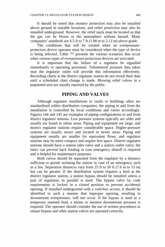
CHAPTER 13: REGULATOR STATION DESIGN
449
It should be noted that monitor protection may also be installed above ground in suitable locations, and relief protection may also be installed underground. However, the relief stack must be located so that the gas can be blown to the atmosphere without hazard. Many companies’ standards are 6.5 ft to 7 ft (1.98 m to 2.13 m) above grade.
The conditions that will be created when an overpressure-protection device operates must be considered when the type of device is being selected. Table 77 presents the various scenarios that occur when various types of overpressure-protection devices are activated.
It is important that the failure of a regulator be signalled immediately to operating personnel. Telemetered pressure data taken near the regulator outlet will provide this information effectively. Recording charts at the district regulator station do not reveal their data until a scheduled chart change is made. Blowing relief valves in a populated area are usually reported by the public.
PIPING AND VALVES Although regulator installations in vaults or buildings often are
standardized within distribution companies, the piping to and from the installation is controlled by local conditions and varies accordingly. Figures 144 and 145 are examples of piping configurations to and from district regulator stations. Low pressure systems typically are older and usually are found in urban areas. Piping and equipment are large, and district regulator stations require considerable space. Higher-pressure systems are usually newer and located in newer areas. Piping and equipment usually are smaller for equivalent flows, and regulator stations may be more compact and require less space. District regulator stations should have a station inlet valve and a station outlet valve; the latter can prevent back feeding in case emergency shutoff is required and is helpful for maintenance purposes.
Both valves should be separated from the regulator by a distance sufficient to permit isolating the station in case of an emergency such as a fire. Separation distances vary from 25 ft to 50 ft (7.6 m to 15 m) but can be greater. If the distribution system requires a feed at the district regulator station, a station bypass should be installed unless a pair of regulators in parallel is used. The bypass valve by code requirements is locked in a closed position to prevent accidental opening. If installed underground with a curb-box access, it should be identified in such a manner that improper opening, resulting in downstream overpressure, will not occur. If the bypass is used as a temporary manned feed, a means to monitor downstream pressure is required. The operator should consider the use of written procedures to ensure bypass and other station valves are operated correctly.

TABLE 77 Comparison of Overpressure-Protection Devices
Condition with Device Activated Relief Working Monitor Monitor
Series Regulation
Shut Off
Relief Monitor
Customer remains on Yes Yes Yes Yes
No
Yes
Gas vented to atmosphere
Yes No No No
No
Minor
Manual resetting required
No No No No
Yes
No
Regulator capacity reduced
No Yes Yes Yes
No
No
Immediate action by gas company required?
Yes No No No
Yes
Maybe
Condition during Normal Operation Activated No Yes No Yes No No
SYSTEM
DESIG
N
450

CHAPTER 13: REGULATOR STATION DESIGN 451
The selection of shutoff valves is important in the design of the district regulator station. Valves must be accessible and operable under emergency conditions. Valve types available are plug valves (lubricated and non-lubricated), gate valves (rising and non-rising stem), and ball valves. Plug valves usually have restricted ports, which may be a factor at high flow rates in lower pressure applications. The lubricated plug may require lubrication before it can be operated and/or shut off tightly.
Over lubrication, which admits grease into the gas stream, should be avoided. Plug valves provide good throttling capabilities due to their internal design and are recommended for bypass and blow off applications. Gate valves usually have full-open bore. When installed underground, they should have a non-rising stem to avoid exposing threads to dirt and moisture in the open position. Gate valves normally operate easily without maintenance, although some have been susceptible to stem leaks through the packing gland and to the collection of foreign material in the bottom seating area. Ball valves are available with either full-opening or restricted ports; they are easy to operate and provide good shutoff if proper seat materials are used. Due to lack of lubrication requirements and small pressure drops, the ball or gate valves are best located between regulators and meters.
When vaults are used, the designer of the district regulator station should consider the effect of a single incident-such as an explosion-that could result in system overpressure due to the failure of both the regulator and the overpressure device. To prevent such an occurrence, there should be adequate separation between the regulator and the protection device.
Piping and control lines shall be located so as to minimize accidental damage. Piping and control lines in pits and vaults should be protected against atmospheric corrosion; tubing should be stainless steel.
INLET, OUTLET, BYPASS, AND CONTROL PIPING DESIGN
Proper pipe size selection, piping and fitting configuration, and control-line location are important to obtaining optimum performance from a district regulator installation. Inlet and outlet piping should be sized for maximum flow conditions, with velocity considered for noise control. Anticipated future load also should be considered. Selection of gradually tapered expanders and long-radius bends helps reduce turbulence, noise, vibration, and pressure loss.
Bypass piping should be sized in accordance with the required station capacity, and the manual throttle valve should be within sight of a connection for an outlet pressure gage.
Pressure-sensing control piping taps should be located downstream in the larger sized outlet piping. The pressure-sensing tap location must be located at a sufficient distance downstream from valves, tees, ells, or

452 SYSTEM DESIGN
other fittings to minimize turbulence in the gas stream; eight to ten pipe diameters is recommended as a minimum. McGuire gives examples of several different regulator station designs.
3
EXAMPLE
The following is a simplified exercise in sizing components for a district regulator station:
Load requirement 100 Mft3/h (2.83×10³ m3/h) MAOP of supply line 60 psig (414 kPa) Minimum pressure in the supply line 30 psig (207 kPa) MAOP of distribution system 10 psig (69 kPa)
Use the above ground regulator and relief valve configuration shown in Figure 142 and the regulator station layout shown in Figure 144 and the following assumptions:
3 in. (76 mm) inlet piping 4 in. (101 mm) outlet piping 2 in. (51 mm) regulator 3 in. (76 mm) relief valve 2 in. (51 mm) by pass
Pipe and fittings from the supply line to the regulator include the following in equivalent length of 3 in. (76 mm) pipe:
1 3 in. (76 mm) gate valve 2 ft (0.6 m) 3 3 in. (76 mm) 90° long-radius weld ells 12 ft (3.7 m) 1 3 in. × 2 in. (76 mm × 51 mm) weld tee (run) 5 ft (1.5 m) 1 3 in. (76 mm) plug valve 12 ft (3.7 m) 1 3 in. × 2 in. (76 mm × 51 mm) weld reducer 5 ft (1.5 m) 3 in. (76 mm) pipe 65 ft (19.8 m)
Total 3 in. (76 mm) pipe equivalent 101 ft (30.8 m)
The capacity of the regulator can be obtained from manufacturers in the form of formulas, tables, nomographs, or PC software.
Calculation of the pressure drop for 100 Mft3/h (2.83×10³ m3/h) flow with 30 psig (207 kPa) inlet and 101 ft (30.8 m) of 3 in. (76 mm) pipe gives 4.4 psi (30 kPa) using the Weymouth equation. Minimum pressure at the regulator now is 30 - 4.4 = 25.6 psig (177 kPa). The 2 in. (51 mm) regulator with 1¾ in. (45 mm) double-ported body is rated at 104 Mft3/h (2.95×10³ m3/h) at 25 psig (172 kPa) inlet. Thus, the regulator is adequate.
A similar pressure drop determination for the 2 in. (51 mm) bypass will show that it also is adequate.
The relief valve must be sized for regulator failure under maximum pressure conditions. The allowable pressure increase, as per 192.201, for this 10 psig (69 kPa) system is 5 psi (34.5 kPa) (MAOP plus 50%). At a 12 psig (83 kPa) relief setting, the relief valve will relieve 130

CHAPTER 13: REGULATOR STATION DESIGN 453
Mft3/h (3.68×10³ m3/h) with less than a 3 psi (21 kPa) increase over set point. At an inlet pressure of 60 psig (414 kPa), the failed regulator will pass about 700 Mft3/h (1.98×10⁴ m3/h). The 3 in. (76 mm) relief valve is not adequate.
A 4 in. (102 mm) relief valve at the same relief setting will relieve 235 Mft3/h (6.65×10³ m3/h) - the 4 in (102 mm) relief valve is adequate. We should install a 2 in. x 4 in. (51 mm × 102 mm) weld expander at the regulator outlet and a 4 in. (102 mm) full-open gate valve (locked open) ahead of the 4 in. (102 mm) relief valve. The relief valve should be installed downstream of the bypass and downstream of the regulator sensor line tap.
The outlet piping includes the following in equivalent length of 4-in. pipe:
1 2 in. × 4 in. (51 mm × 102 mm) weld expander 8 ft (2.4 m) 1 4 in. (102 mm) weld tee (branch) 6 ft (1.8 m) 1 4 in. × 2 in. (102 mm × 51mm) weld tee (run) 7 ft (2.1 m) 2 4 in. (102 mm) weld ells 10 ft (3.0 m) 1 4 in. (102 mm) gate valve 2 ft (0.6 m) 4 in. (102 mm) pipe 20 ft (6.1 m)
Total 4 in. (102 mm) pipe equivalent 63 ft (19 m)
The pressure drop for 100 Mft3/h (2.83×10³ m3/h) flow with 10 psig (69 kPa) inlet and 100 ft (30.5 m) of 4 in. (102 mm) pipe is 1.1 psi (7.6 kPa). This leaves 8.9 psig (61 kPa) delivery pressure into the distribution main at maximum flow. In this example, it would be advisable to run the regulator's downstream control line directly to the distribution main to eliminate the effect of the pressure drop through the outlet piping.
Although the 4 in. (102 mm) piping immediately downstream of the regulator is adequate in terms of velocity up to 4 in. (102 mm) gate valve downstream of the regulator, the piping downstream of the 4 in. (102 mm) gate valve needs to be increased to a larger size in order to reduce the velocity and the associated pressure drop to the distribution main. This outlet header piping should be at least as large as the distribution main to which the station is being connected. At the A.G.A System Capacity Design Best Practices Roundtable held in September 1997, the general consensus was that the velocity in outlet header piping should be less than 65 ft/s (20 m/s). Solving the velocity equation given for pipe size results in a required internal diameter of 6.835 in. (173.6 mm). This would require an 8 in. (204 mm) pipe (either plastic with an underground transition or steel) to achieve a velocity lower than 65 ft/s (20 m/s).
)s/ft(V)psia(P)h/Mft(Q750.)in(ID
3
××
=

454 SYSTEM DESIGN
657.24100750
ID×
×= = 6.835 in. (173 mm)
Section 9.5 of A.G.A. Gas Measurement Manual Part No. 9, 1988 is another good reference for valves and piping configurations.