leak testing in the automotive...
TRANSCRIPT

A Comprehensive Guide to Leak Detection
Leak Testing in the Automotive Industry

2
Foreword
Quality assurance is an issue of growing importance to the entire automotive sector. The demands are
rising. Manufacturers already demand leak proof components from their suppliers. Vehicle components
manufacturers define leak rates that must not be exceeded for volume production, whether it‘s an oil pan,
brake boosters or injection valves.
It is critical that nothing escapes through leaks, such as the refrigerant in the air conditioning system,
the transmission fluid in the torque converter of an automatic transmission, or the helium-argon mixture
in the inflator of an airbag. As the demand for leak proof components increases, a stricter legislation
may lead to new, stiffer tightness requirements. Just think of the stringent California and U.S. legislation
regarding the emission of hydrocarbons and their implications for the leakage requirements for fuel tanks
and lines.
Industrial leak testing and leak detection are not simple issues. Even the choice of the appropriate test
method must be carefully considered. Which method is ideal for a specific application depends on many
factors. Sensitivity plays a role, as well as the marginal leak rate of the method used, and the cycle times
that can be achieved in integral testing on the production line. The repeatability and reliability of the
testing process also should be considered along with the capital expenditure and operating costs, which
are all based on the particular test method.
2
3
Part 1 explains the fundamentals of leak testing - Page 7
This e-book provides an overview of the broad field of leak testing and leak detection in the automotive
industry and is divided into two parts. The first deals with the general principles of leak testing. The ex-
isting methods are described: bubble test, pressure decay testing, and helium testing in accumulation or
vacuum chambers. The strengths and weaknesses of each process are explained, and attention is given
to the typical challenges associated with each. The most commonly used tracer gases - helium, hydro-
gen and forming gas - are discussed, as well as final operating media such as R1234yf or CO2. The var-
ious units of the leak rate, such as atm, cc/s, sccm, mbar, l/s and g/a are also explained.
Part 2 explains leak testing in the automotive industry - Page 25
In the second part of this e-book you will learn about the specific application of leak testing and leak de-
tection processes in the automotive industry. It includes an explanation of which vehicle components are
typically tested and the methods and leak rates employed. This section also provides some insight about
where to expect increased tightness requirements in the near future. This includes components of the air
conditioning system, the drivetrain emissions and any directly safety-related parts of the vehicle.
Part 2 illustrates in which applications older methods are not sufficient, such as bubble test, pressure
decay and differential pressure methods. These methods sometime give a false sense of security. Last
but not least, at the end of the second part, you will learn about the top 10 most common errors in leak
testing. These includes contaminated test pieces, ignoring temperature and pressure changes in the
testing process, and unidentified creep and gross leaks.
This e-book provides a reliable guide to leak detection that you can refer back to often as questions arise.
However, the only way to avoid the many possible pitfalls of leak detection is to be properly informed.
The proper selection, installation and operation of the optimal procedure, and the ideal test bench or
system are all critical to your success. Contact INFICON , your leak detection solutions partner, with any
questions you may have.
Foreword
4
Table of ContentsPart 1Fundamentals of Leak Testing
1.1 Methods without tracer gas 8
1.1.1 Bubble test 8
1.1.2 Soap spray test 10
1.1.3 Pressure tests with air 11
1.1.3.1 Pressure decay test 11
1.1.3.2 Differential pressure test 12
1.1.3.3 Pressure increase test 14
1.2 Methods with tracer gas 15
1.2.1 Helium tracer gas 15
1.2.2 Hydrogen tracer gas (forming gas) 15
1.2.3 Operating fluid as tracer gases 15
1.2.4 Inside-out and outside-in methods 16
1.2.5 Vacuum method 17
1.2.6 Accumulation method 18
1.2.7 Accumulation method in a high vacuum 19
1.2.8 Sniffer leak detection 19
1.2.9 Evacuation, filling, gas recovery 20
1.3 Leak rates and types of leaks 21
1.3.1 Types of leaks 21
1.3.2 Units for the leak rate 21
1.3.3 Size of leaks 22
1.3.4 Factors influencing the leak rate 23
Table of Contents

5
Part 2Leak Testing in the Automotive Industry
2.1 Leak limits are becoming more stringent 26
2.2 Components, methods, and typical leak rates 29
2.2.1 Air conditioning 29
2.2.2 Powertrain 31
2.2.3 Fuel systems 32
2.2.4 Oil and water circuits 33
2.2.5 Safety features 34
2.2.6 Wheel rims, shock absorbers and other components 35
2.3 Ten most common errors in leak testing 36
2.3.1 Using the wrong method for the test leak rate 37
2.3.2 The wrong point in time in the production process is chosen for testing 37
2.3.3 The test piece is already contaminated 38
2.3.4 Temperature changes are ignored 38
2.3.5 The test pressure fluctuates 39
2.3.6 Stringer leaks and gross leaks are underestimated 39
2.3.7 The testers do not know what they are actually measuring 40
2.3.8 No calibration of the test equipment takes place 41
2.3.9 Maintenance of the test system is neglected 41
2.3.10 We can do it ourselves 42
Table of Contents
6
Appendix
3.1 Web links 44
3.1.1 Videos 44
3.1.2 Description of leak testing applications
45
3.2 Source of illustrations 46
3.3 About INFICON 47
3.4 References 48
3.4.1 Manufacturers of passenger cars 48
3.4.2 Manufacturers of heavy duty vehicles 48
3.4.3 Automotive component suppliers 49
3.5 Contact information 51
Table of Contents

7
Part 1Fundamentals of Leak Testing

8
1.1.1 Bubble test
The water bath test, most commonly known as
the bubble test is simply bubbles emerging from
a test piece. Bubble testing is based on the as-
sumption that what works with bike tires also will
work well in production. In the bubble test method,
the test piece is first filled with compressed air and
then submerged in a water tank. The tester then
observes whether bubbles rise. Ideally, the tester
also can see where the bubbles are coming from.
The bubble test is intended not only as an integral
leak test, but also for leak detection. The test not
only allows for a leak or no-leak statement, but also
identifies the leak location.
For cost reasons, typically air is used for test-
ing. In production conditions, leak rates of up to
5x10⁻² mbar l/s (five hundredth of a millibar liters per
second = 0.05 mbar l/s) can be identified reliably. With
this leak rate there is a relatively clear and visible,
albeit slow, stream of bubbles. With even smaller
leaks, the test piece has to stay under water for a
considerably longer time to produce just one bubble.
1.1 Methods without tracer gas
Part 1 Fundamentals of Leak Testing
The detection limit of bubble testing deteriorates depending on the geometry of the test piece
Water bath testing: as simple as testing bike tires

9
In literature, a theoretical limit of detection (the
smallest barely detectable leak rate) of up to
1x10⁻⁴ mbar l/s is usually quoted. Under ide-
al conditions, a leak rate of 1x10⁻³ mbar l/s
(= 0.001 mbar l/s) will create one bubble per second.
At a leak rate of 1x10⁻⁴ mbar l/s, it takes 30 seconds
to form a single bubble. In real world applications,
the detection limit of this method deteriorates sig-
nificantly, depending on the geometry of the test
piece and some other factors.
A bubble that would ascend unimpeded in free water
will often be hindered from ascending from a test
piece that has a complex shape. Also, if leaks are
caused by porosity – for example in casted parts – in
many cases no bubble will develop. Porosity leaks
are often made up of millions of very small holes
which together accumulate to a significant leak rate.
However, each hole individually is too small to allow
for enough air output to form a bubble due to the
surface tension of water.
At first glance, a bubble test is very simple and
inexpensive, but this method does have some
disadvantages. One of the main problems is that
after the bubble test, the test piece is wet and must
be dried. This step is time consuming and costly, but
must be done to avoid any consequential damage
that may be caused by corrosion. This method is not
suitable for test pieces that cannot tolerate moisture.
Another limiting aspect is the person testing the
part, or the human factor. Whether bubbles are
detected or not depends on the individual tester.
Another problem that should not be underestimated
is the clear view of the test piece and bubbles. If the
test piece has a complex shape, or the location of
the leak cannot be seen, a tester may not see the
emerging bubble. There also is the inevitable process
contamination. The water in the test tank becomes
cloudy after four to eight weeks -- sometimes even
within one day, depending on the condition of the
part being tested -- and must be replaced. This often
creates additional costs. To promote the formation
of bubbles, typically chemicals are added to the
water to reduce the surface tension of the water.
The tank contents must therefore be disposed of
as hazardous waste.
Part 1 Fundamentals of Leak Testing
10
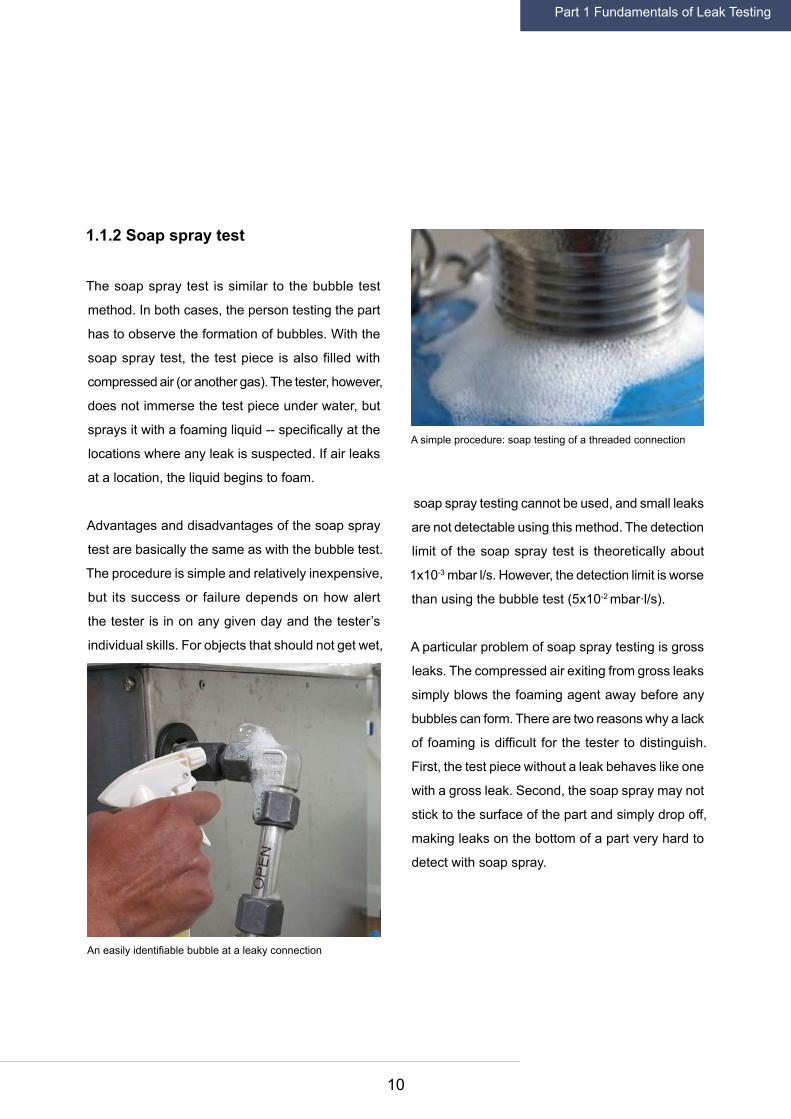
1.1.2 Soap spray test
The soap spray test is similar to the bubble test
method. In both cases, the person testing the part
has to observe the formation of bubbles. With the
soap spray test, the test piece is also filled with
compressed air (or another gas). The tester, however,
does not immerse the test piece under water, but
sprays it with a foaming liquid -- specifically at the
locations where any leak is suspected. If air leaks
at a location, the liquid begins to foam.
Advantages and disadvantages of the soap spray
test are basically the same as with the bubble test.
The procedure is simple and relatively inexpensive,
but its success or failure depends on how alert
the tester is in on any given day and the tester’s
individual skills. For objects that should not get wet,
soap spray testing cannot be used, and small leaks
are not detectable using this method. The detection
limit of the soap spray test is theoretically about
1x10⁻³ mbar l/s. However, the detection limit is worse
than using the bubble test (5x10⁻² mbar∙l/s).
A particular problem of soap spray testing is gross
leaks. The compressed air exiting from gross leaks
simply blows the foaming agent away before any
bubbles can form. There are two reasons why a lack
of foaming is difficult for the tester to distinguish.
First, the test piece without a leak behaves like one
with a gross leak. Second, the soap spray may not
stick to the surface of the part and simply drop off,
making leaks on the bottom of a part very hard to
detect with soap spray.
An easily identifiable bubble at a leaky connection
A simple procedure: soap testing of a threaded connection
Part 1 Fundamentals of Leak Testing

11
1.1.3 Pressure tests with air
There are three methods that identify leaks through
measuring pressure changes: the pressure decay
method, the differential pressure method and the
pressure increase method. All three methods are
used for integral leak testing, and their goal is a leak/
no-leak statement for the entire part. Of these three
methods used in the industrial sector, the pressure
decay test is the most common.
1.1.3.1 Pressure decay test
With the pressure decay test method, the test piece
is filled to a defined overpressure with air or another
gas. After filling the test piece it is always necessary
to wait before measuring until the parameters have
stabilized and the pressure has settled.
Usually this takes longer than the actual measure-
ment. Exactly how long depends on the material
and surface of the part being tested. The pressure
in the test piece is then measured over a defined
time interval. If the pressure reduces over time, there
is a leak. The leak rate is calculated by multiplying
the measured pressure variation with the internal
volume of the test piece and divided by the length
of the time interval. The theoretical detection limit
of the pressure decay test is ultimately no better
than that of the bubble test or soap spray test:
5x10⁻⁴ mbar∙l/s, however, often only values of
1x10⁻² mbar∙l/s or higher can be achieved.
The primary reason why the sensitivity of the pres-
sure decay test is 10 times worse is temperature
fluctuations. The measured pressure is naturally
dependent on the temperature.
The drawback of pressure decay testing (lower row with leak) is temperature fluctuations
Part 1 Fundamentals of Leak Testing

12
A sample calculation:
If a test piece is filled to a volume of 3 liters with a
pressure of 2.5 bar (25 psi), and the compressed air
warms up to 40° C, the air then cools down again
during the test interval of 20 seconds. If the air at the
end of the measurement is only 1° C colder than at
the beginning of the measurement, the pressure in
the test piece is correspondingly less, and the leak
rate appears larger than it really is by 1.2 mbar∙l/s.
As a result, it is a thousand times higher than the
theoretical detection limit of 1x10⁻³ mbar∙l/s.
When using the pressure decay test, even a very
small increase in temperature can cause a leak that
cannot to be detected. If the temperature in a test
piece increases during the measurement interval of
20 seconds by only 0.1°C, and with 3 liters of volume
and 2.5 bar air pressure, there is an increase of the
internal pressure to 2.50085 bar. Accordingly, any
leak rate appears smaller than it actually is by a rate
of 0.13 mbar∙l/s. To reach the theoretical detection
limit of 1 x 10⁻³ mbar∙l/s (0.001 mbar∙l/s) is, of course,
impossible. The example shows that an increase in
temperature of 0.1°C increases the detection limit by
a factor of 100. This is why after filling, long settling
times are built into the procedure so that pressure
and temperature during the test are stable.
Temperature fluctuations are the biggest drawbacks
of pressure decay testing. Temperature and pressure
changes can be caused by sunlight, air movement,
touch and by filling under pressure. Any test pieces
that deform under the test pressure and change
their volume, such as plastic parts, are difficult to
reliably test using the pressure decay method. Also,
any contact or deformation may quickly undermine
the validity of each pressure decay test.
1.1.3.2 Differential pressure test
The differential pressure test also measures pressure
differences. However, it compares the pressure in
the test piece with the pressure in a reference object
whose tightness is known. Both the test piece and
the reference piece are simultaneously filled to the
same overpressure. Any pressure differences are
then measured with a differential pressure sensor
for the duration of a defined time interval. The leak
rate is the result of the pressure difference times
the internal volume of the test piece divided by the
time interval of the measurement. The difference
between two pressures can be measured with
a higher resolution than for the pressure decay
method. The theoretical detection limit of the dif-
ferential pressure measurement is 10 times better
than that of the pressure decay test, 1x10⁻⁴ mbar∙l/s.
Temperature fluctuations have less influence on
differential pressure test, as long as the fluctuations
act to the same extent and at the same time on both
the test piece and the reference piece.
Part 1 Fundamentals of Leak Testing

13
However, the temperature effects as a result of
filling only affect the test piece unless you also fill
the reference piece anew every time. The problem
is that after many fill cycles, the reference piece can
become fatigued or accumulate heat from previous
filling processes and then behave differently from the
test piece. Ideally, you swap the reference piece for
each test so it can settle down. Particular problems
with the differential pressure test are more notable
with easily deformable test pieces (such as plastic)
or in those with a large volume. During regular use,
the differential pressure test detection limits of
1x10⁻³ mbar∙l/s are realistic.
Differential pressure testing (lower row with leak) reduces temperature effects
Part 1 Fundamentals of Leak Testing
14
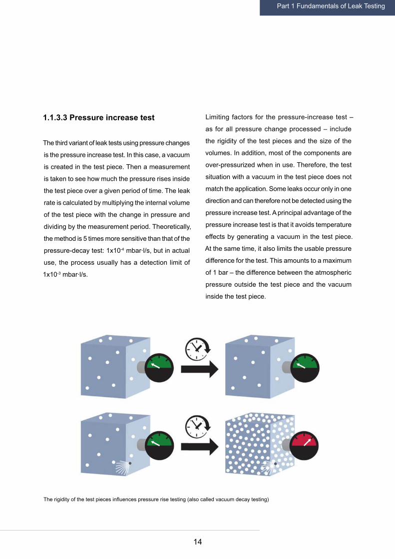
1.1.3.3 Pressure increase test
The third variant of leak tests using pressure changes
is the pressure increase test. In this case, a vacuum
is created in the test piece. Then a measurement
is taken to see how much the pressure rises inside
the test piece over a given period of time. The leak
rate is calculated by multiplying the internal volume
of the test piece with the change in pressure and
dividing by the measurement period. Theoretically,
the method is 5 times more sensitive than that of the
pressure-decay test: 1x10⁻⁴ mbar∙l/s, but in actual
use, the process usually has a detection limit of
1x10⁻³ mbar∙l/s.
Limiting factors for the pressure-increase test –
as for all pressure change processed – include
the rigidity of the test pieces and the size of the
volumes. In addition, most of the components are
over-pressurized when in use. Therefore, the test
situation with a vacuum in the test piece does not
match the application. Some leaks occur only in one
direction and can therefore not be detected using the
pressure increase test. A principal advantage of the
pressure increase test is that it avoids temperature
effects by generating a vacuum in the test piece.
At the same time, it also limits the usable pressure
difference for the test. This amounts to a maximum
of 1 bar – the difference between the atmospheric
pressure outside the test piece and the vacuum
inside the test piece.
The rigidity of the test pieces influences pressure rise testing (also called vacuum decay testing)
Part 1 Fundamentals of Leak Testing

15
The methods using tracer gas are among the most
sensitive leak testing methods. The most common
tracer gases are helium and diluted hydrogen,
which is normally used in a forming gas mixture.
Leak testing and sniffer leak detection with tracer
gases use the pressure difference that is created
between the inside and the outside of a test piece
so that the tracer gas can flow through a possible
leak and be selectively detected.
1.2.1 Helium tracer gas
Helium is the most widely used of all testing or
tracer gases. The noble gas only occurs atomical-
ly and is chemically inert. Helium is non-toxic and
non-flammable. Also, its low molecular weight of
only 4 makes it ideal to be used as a tracer gas.
An important advantage is also its low background
concentration: The natural concentration of helium
in air is 5 ppm.
1.2.2 Hydrogen tracer gas (forming gas)
Probably the biggest advantage of hydrogen gas
for leak testing and leak detection is the very low
natural background concentration of hydrogen in air,
which is 0.5 ppm. A disadvantage of pure, molecular
hydrogen gas (H2) is, of course, its flammability.
Such risks, however, are not a problem, as pure
hydrogen is never used as a tracer gas. For leak
testing and leak detection, a so-called forming gas
is used, which is a mixture of 95% nitrogen (N2) and
5% hydrogen (H2). The more affordable forming
gas, which is also used as a shielding gas during
welding, is non-flammable at hydrogen concentra-
tions of 5% or less.
1.2.3 Operating fluid as tracer gases
Sometimes gaseous operating fluid is used for
leak testing and leak detection. The test piece is
filled according to its purpose and is then used for
leak detection. For example, the propellant and
refrigerant R-134a (chemically: 1,1,1,2-tetrafluo-
roethane) functions as the tracer gas at the same
time, or sulfur hexafluoride (SF6) which can be
directly detected. This gas serves as an insulating
gas for medium and high voltage applications and,
for example, in gas-insulated high voltage switches
and switchgear. SF6 is the most effective quenching
1.2 Methods with tracer gas
Part 1 Fundamentals of Leak Testing

16
gas, but it is a greenhouse gas and its use as a pure
tracer gas is prohibited. The same applies to many
older refrigerants. All of the procedures that use
the operating fluid as tracer gases are not used for
integral leak testing during production, but to find
subsequent leaks.
1.2.4 Inside-out and outside-in methods
Methods using tracer gas can be divided into two
broad classes depending on the outlet or inlet direc-
tion of the tracer gas. Methods in which the tracer
gas is introduced into a test piece so that it can be
released into the environment from possible leaks
are referred to as the inside-out method.
A sniffer leak detection method is used to locate
these leaks. When using the sniffer method, a
measuring probe is guided manually over the test
piece filled with the tracer gas. There are two very
widespread methods for integral leak testing that
work on the inside-out principle. One method is
testing in the accumulation chamber. The second
is testing in the vacuum chamber. Both measure
how much tracer gas escapes from a test piece in
the respective test chamber.
Both outside-in methods are based on the use
of vacuum. In the vacuum leak detection test, a
vacuum is created in the test piece and the tracer
gas is sprayed from the outside. Location and size
of the leak is determined by how much tracer gas
inside the test object can be detected in a certain
time interval.
The other outside-in method is the leak testing in
a chamber. The test piece is placed in a chamber
and a vacuum is created inside the test piece. The
chamber is filled with the tracer gas, which then
penetrates through any leaks into the vacuum in
the test piece, where it can be measured.
The bombing method combines both the inside-out
and outside-in methods. Bombing first uses the
outside-in, and then the inside-out principle. The
test piece is brought into the first chamber in which
a tracer gas overpressure is produced so that the
tracer gas enters through any leaks into the interior
of the test piece. Then the test piece is placed in
Outside-In
Sniffer leak testing
Vacuum leak testing
Accumulation leak testing
Bombing
Vacuum leak testing
Spraying
Inside-Out
Bombing
Part 1 Fundamentals of Leak Testing

17
a vacuum chamber so that the tracer gas from the
interior of the test piece can escape by the same leak
into the vacuum chamber, where it can be measured.
The bombing leak detection method makes sense
for hermetically sealed test pieces without their
own internal pressure, where evacuation or filling is
not an option -- for example with sensor housings.
Often the bombing test method serves to exclude
a possible penetration of moisture.
One difficulty with this method can be that the test
piece is usually not filled to 100% with helium, which
degrades the detection limit. Another problem is
posed by gross leaks. If during the evacuation of the
vacuum chamber the helium contained in the test
object is also fully evacuated, then later no helium
can escape and be measured - the test piece will
appear incorrectly as leak proof.
1.2.5 Vacuum method
Integral leak testing in a vacuum chamber is often
an inside-out test. The test piece is first placed
in a chamber, either manually by an operator or
automatically, by a robot arm. A pump generates
a vacuum in the test chamber, and the interior of
the test part is filled with helium via correspond-
ing connections. Although this method is relative-
ly expensive because of the more stringent leak
rate requirements for the chamber and the costly
vacuum pump, it does have some major advantages.
First, the helium testing in the vacuum chamber is
the most sensitive of all of the tracer gas methods.
The mass spectrometer used for the detection of
the helium can, under best conditions, determine
leak rates down to 1x10-12 mbar∙l/s. The vacuum
method is particularly well-suited for production
line testing and in many automated production pro-
cesses, where each part is subjected to integral leak
testing. Another advantage of the vacuum method
is short cycles and fast cycle times, especially in
Vacuum leak testing (with vacuum in the test piece) is often well suited for production line testing
Leak testing via bombing lends itself to hermetically sealed test pieces
Part 1 Fundamentals of Leak Testing

18
fully automated test sequences. In addition, the
sensitivity of the vacuum method often allows for the
reduction of the helium concentration significantly,
to approximately only 1%, which also reduces the
cost of the tracer gas accordingly.
1.2.6 Accumulation method
Tracer gas in the accumulation chamber also falls
into the category of inside-out test procedures, but
is much less expensive than a test in the vacuum
chamber. The test piece is placed in a simple ac-
cumulation chamber, which is required to meet
significantly less stringent sealing requirements
than a vacuum chamber. Odor tightness is already
sufficient for an accumulation chamber. The interior
of the test piece is filled with a tracer gas -- often
with helium.
The tracer gas then escapes from any leaks in the
test piece. To insure that the tracer gas escaping
is evenly distributed in the accumulation chamber,
usually a fan is used. The leak rate is calculated by
determining how much tracer gas escapes from the
leak during a defined period of time and collects in
a given volume in the test chamber.
Such leak testing with helium in an inexpensive
accumulation chamber instead of installing, oper-
ating, and having to maintain an elaborate vacuum
chamber, first became popular when INFICON
brought its patented Wise TechnologyTM sensor to
market. The inexpensive Wise Technology sensor
measures exclusively the helium concentration, does
not need any vacuum, and under best conditions
can detect leak rates in the accumulation chamber
as low as 5x10⁻⁶ mbar∙l/s.
Leak testing using a mass spectrometer, on the
other hand, normally requires a vacuum. The actual
testing in the vacuum chamber takes two to three
seconds, as opposed to a test in the accumulation
chamber that takes about five times longer. However,
when calculating the cycle time of a vacuum test,
one must also add in the time for evacuation, which
is not needed with the accumulation method. The
accumulation method has a cost benefit two to four
times lower than the faster vacuum test.
Accumulation leak testing in a simple accumulation chamber does not need a vacuuum
Part 1 Fundamentals of Leak Testing

19
1.2.7 Accumulation method in a high vacuum
Particularly small leak rates can be measured by
combining the principles of accumulation and the
vacuum chamber. Currently the leak detector capable
of detecting the smallest leak rates is a vacuum
leak tester from INFICON. The Cumulative Helium
Leak Detector (CHLD) Pernicka 700H works on the
principle of accumulation in an ultrahigh vacuum.
With its precise mass spectrometer, it detects the
lowest leak rates down to as little as 4x10-14 mbar∙l/s.
1.2.8 Sniffer leak detection
The so called sniffer leak detection with tracer gas
is typically used to find the exact location of a leak.
Often sniffer leak detection is used after a failure
during an integral test. The sniffer leak detection
also is an inside-out method: The part to be tested
is pressurized with tracer gas so that tracer gas
escapes through the leak. The sniffer tip of the leak
detector is then guided across the surface of the test
part (manually or by a robot) until the leak detector
identifies the location with the highest leak rate.
Because the sniffer line of the leak detector sucks
in a mixture of air and escaping tracer gas, a low
background concentration of tracer gas is desirable.
For sniffer leak detection, helium or forming gas can
be used as tracer gas, but gaseous operating media
like refrigerants (R134a, CO2, etc.) or SF6 can be
used. For a sniffer leak detector like the INFICON
Protec P3000(XL), the smallest detectable leak rate
is in the range of 1x10⁻⁷ mbar∙l/s.
Sniffer leak testing (with manual sniffer probe) finds the exact location of a leak
Part 1 Fundamentals of Leak Testing
20
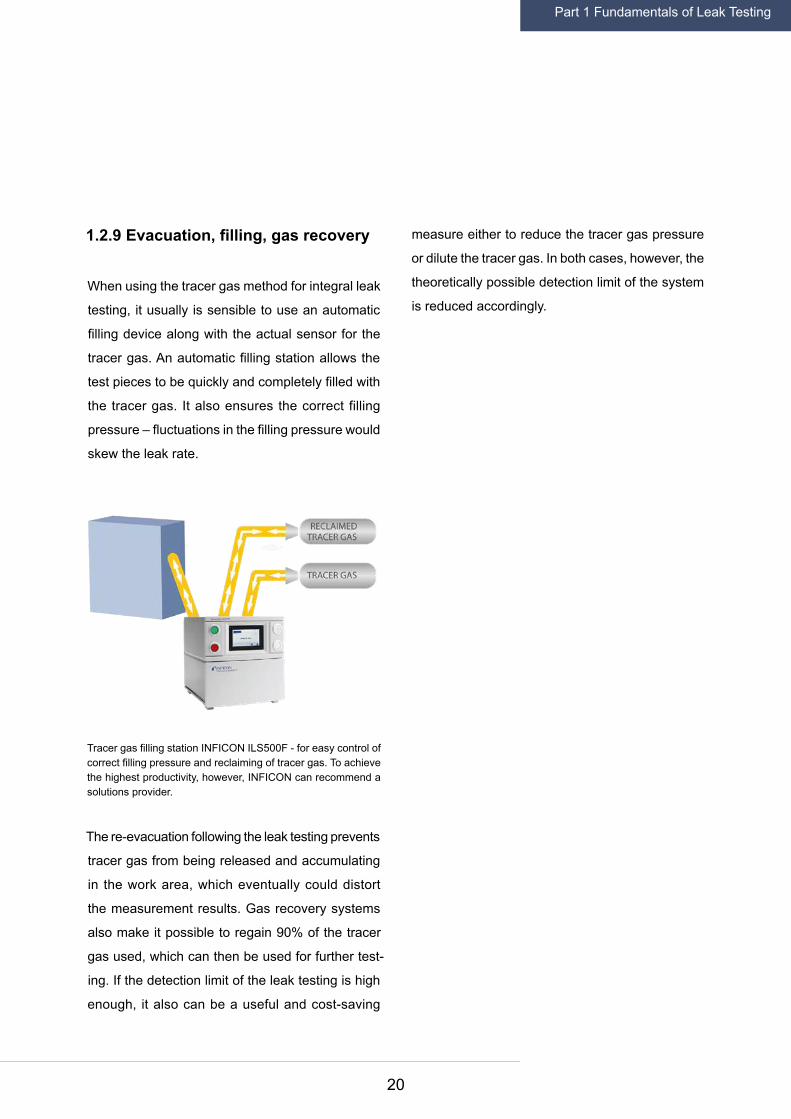
1.2.9 Evacuation, filling, gas recovery
When using the tracer gas method for integral leak
testing, it usually is sensible to use an automatic
filling device along with the actual sensor for the
tracer gas. An automatic filling station allows the
test pieces to be quickly and completely filled with
the tracer gas. It also ensures the correct filling
pressure – fluctuations in the filling pressure would
skew the leak rate.
The re-evacuation following the leak testing prevents
tracer gas from being released and accumulating
in the work area, which eventually could distort
the measurement results. Gas recovery systems
also make it possible to regain 90% of the tracer
gas used, which can then be used for further test-
ing. If the detection limit of the leak testing is high
enough, it also can be a useful and cost-saving
measure either to reduce the tracer gas pressure
or dilute the tracer gas. In both cases, however, the
theoretically possible detection limit of the system
is reduced accordingly.
Tracer gas filling station INFICON ILS500F - for easy control of correct filling pressure and reclaiming of tracer gas. To achieve the highest productivity, however, INFICON can recommend a solutions provider.
Part 1 Fundamentals of Leak Testing
21
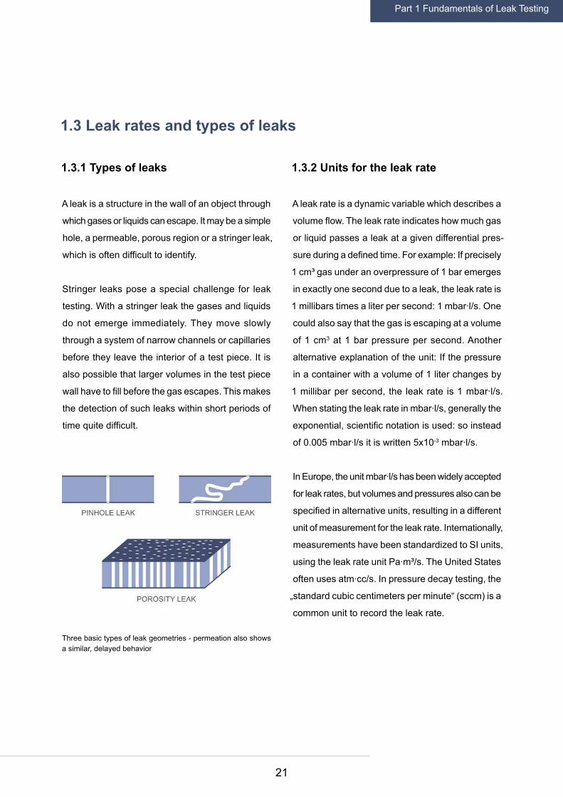
1.3.1 Types of leaks
A leak is a structure in the wall of an object through
which gases or liquids can escape. It may be a simple
hole, a permeable, porous region or a stringer leak,
which is often difficult to identify.
Stringer leaks pose a special challenge for leak
testing. With a stringer leak the gases and liquids
do not emerge immediately. They move slowly
through a system of narrow channels or capillaries
before they leave the interior of a test piece. It is
also possible that larger volumes in the test piece
wall have to fill before the gas escapes. This makes
the detection of such leaks within short periods of
time quite difficult.
1.3.2 Units for the leak rate
A leak rate is a dynamic variable which describes a
volume flow. The leak rate indicates how much gas
or liquid passes a leak at a given differential pres-
sure during a defined time. For example: If precisely
1 cm³ gas under an overpressure of 1 bar emerges
in exactly one second due to a leak, the leak rate is
1 millibars times a liter per second: 1 mbar∙l/s. One
could also say that the gas is escaping at a volume
of 1 cm3 at 1 bar pressure per second. Another
alternative explanation of the unit: If the pressure
in a container with a volume of 1 liter changes by
1 millibar per second, the leak rate is 1 mbar∙l/s.
When stating the leak rate in mbar∙l/s, generally the
exponential, scientific notation is used: so instead
of 0.005 mbar∙l/s it is written 5x10⁻³ mbar∙l/s.
In Europe, the unit mbar∙l/s has been widely accepted
for leak rates, but volumes and pressures also can be
specified in alternative units, resulting in a different
unit of measurement for the leak rate. Internationally,
measurements have been standardized to SI units,
using the leak rate unit Pa∙m³/s. The United States
often uses atm∙cc/s. In pressure decay testing, the
„standard cubic centimeters per minute“ (sccm) is a
common unit to record the leak rate.
1.3 Leak rates and types of leaks
Three basic types of leak geometries - permeation also shows a similar, delayed behavior
Part 1 Fundamentals of Leak Testing

22
1 atm∙cc/s ≈ 1 mbar∙l/s
1 Pa∙m³/s = 10 mbar∙l/s (SI unit)
1 sccm ≈ 1/60 mbar∙l/s
For refrigerants such as R134a, leak rates are
typically stated as a mass flow (escaping mass per
year) rather than a volume flow (escaping volume
at a given pressure in a specific period of time).
Therefore, the unit g/a (grams per year) has been
commonly accepted for refrigerants -- or in the U.S.
oz/yr (ounces per year). The escaping mass always
depends on the molecular weight of the gas. In the
case of R134a the conversion is:
1 g/a = 7.6∙10-6 mbar∙l/s (only for R134a)
1.3.3 Size of leaks
It is useful to consider the relationship between
a helium leak rate and the size of a leak. In other
words: What diameter must a circular hole have to
cause a certain leak rate? Provided the diameter of
the hole is considerably larger than its wall thickness,
a hole of 0.1 mm diameter at a pressure difference
of 1 bar causes a leak rate of 1 mbar∙l/s.
Most bacteria have a diameter between 0.6 to 1
μm. One Ångström is about the diameter of a single
atom. Even at very small leak rates in the order of
10-8 mbar∙l/s, you still have a hole through which
many thousands of helium atoms can flow at the
same time. Which exact leak rate is still tolerable in
a specific case and which test piece can be said to
fail leak testing is always dependent on the specific
quality requirements in the production process. Ac-
cordingly, the selection of the test procedure should
always consider the maximum allowable leak rate.
Diameter of the hole
Size of the helium leak rate
10-2 m = 1 cm
1 mm
0.1 mm
0.01 mm
10-6 m = 1 μm (Bacterium)
0.1 μm
0.01 μm (Virus)
1 nm = 0.001 μm
10-10 m = 0.1 nm = 1 Ångström
10+4 mbar∙l/s
10+2 mbar∙l/s
100 mbar∙l/s
10-2 mbar∙l/s
10-4 mbar∙l/s
10-6 mbar∙l/s
10-8 mbar∙l/s
10-10 mbar∙l/s
~ 10-12 mbar∙l/s
Part 1 Fundamentals of Leak Testing

23
1.3.4 Factors influencing the leak rate
As described in the context of the pressure tests
with air, temperature and pressure changes have
a significant impact on the leak rate. Some test
pieces, such as those made of plastic, deform quite
readily under pressure and temperature changes.
The geometry of a leak also may change under such
conditions -- with corresponding effects on the leak
rate, which is determined during the test.
Also, the exact difference between the pressure in
the test piece and outside, of course, affects the leak
rate. The greater the pressure difference, the greater
the leak rate. When working with tracer gases, the
detectable leak rate can also be dependent on the
exact orientation of the leak.
The exiting tracer gas may not disperse evenly and
because of a breeze of air it may not create the
same concentration of tracer gas in all directions.
For successful leak detection with tracer gases,
such as helium and hydrogen and for localizing
leaks with a manually guided probe, it is important
to take this uneven distribution of tracer gas into
account. Modern equipment for the helium sniffer
leak detection, such as the Protec P3000(XL) draws
in gas with a high gas flow of up to 3,000 sccm to
overcome this problem.
Water-tight
Oil-tight
Vapor-tight
Bacteria-proof
Gasoline-proof
Gas-tight
Technically leak-tight
< 10-2
< 10-3
< 10-3
< 10-4
< 10-5
< 10-6
< 10-10
< 0.6
< 0.06
< 0.06
< 0.006
< 0.0006
< 6 ∙ 10-5
< 6 ∙ 10-9
Requirement Leak rate[mbar∙l/s]
Leak rate[sccm]
LEAK RATES
Part 1 Fundamentals of Leak Testing
24
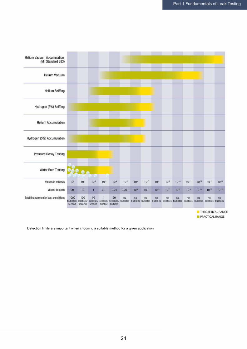
Detection limits are important when choosing a suitable method for a given application
Part 1 Fundamentals of Leak Testing
25
Part 2Leak Testing in the Automotive Industry

26
Automotive manufacturers and suppliers are facing
more stringent leak testing requirements than in
years past. Quality assurance plays an increasingly
important role, and car manufacturers expect their
suppliers to implement appropriate quality control.
If such leak tests are not reliable, this can lead to
costly recalls and damage to their reputation. The
most recent dramatic example was the recall of
millions of products due to potentially defective air-
bags. There was the risk of moisture ingress -- with
serious consequences in the event of spontaneous
airbag deployment.
Such pyrotechnic inflators for airbags today are
often checked to a maximum leak rate in the order
of 10-6 mbar∙l/s. Stringent leak rate requirements
of this magnitude can only be met through the use
of tracer gases. But the leak rate requirements for
injection pumps and fuel systems are also becoming
more demanding. One important reason for this is
the use of fuel injection for increased fuel economy.
Injectors in modern engines work under much higher
pressure -- modern common rail systems operate
with pressures up to 3,000 bar. In spite of the high
internal pressure, the leak rate still must remain low,
leading to more stringent inspections.
In the field of air conditioning systems used in
cars, the industry is also progressing. The use
of fluorinated greenhouse gases, like R134a are
2.1 Leak limits are becoming more stringent
Part 2 Leak Testing in the Automotive Industry
27
being phased out. The EU Directive 2006/40 / EC
prohibits the use of R134a refrigerants beginning
in January 2017. In the USA, the Environmental
Protection Agency announced deadlines to end
the use of R134a because safer, climate-friendlier
alternatives are now available. R134a will be banned
in new motor vehicles starting in 2020 (model year
2021) and replaced by a coolant with a significantly
lower Global Warming Potential (GWP). Alternatives,
such as using CO2 as a refrigerant are safe and can
be gained from the atmosphere.
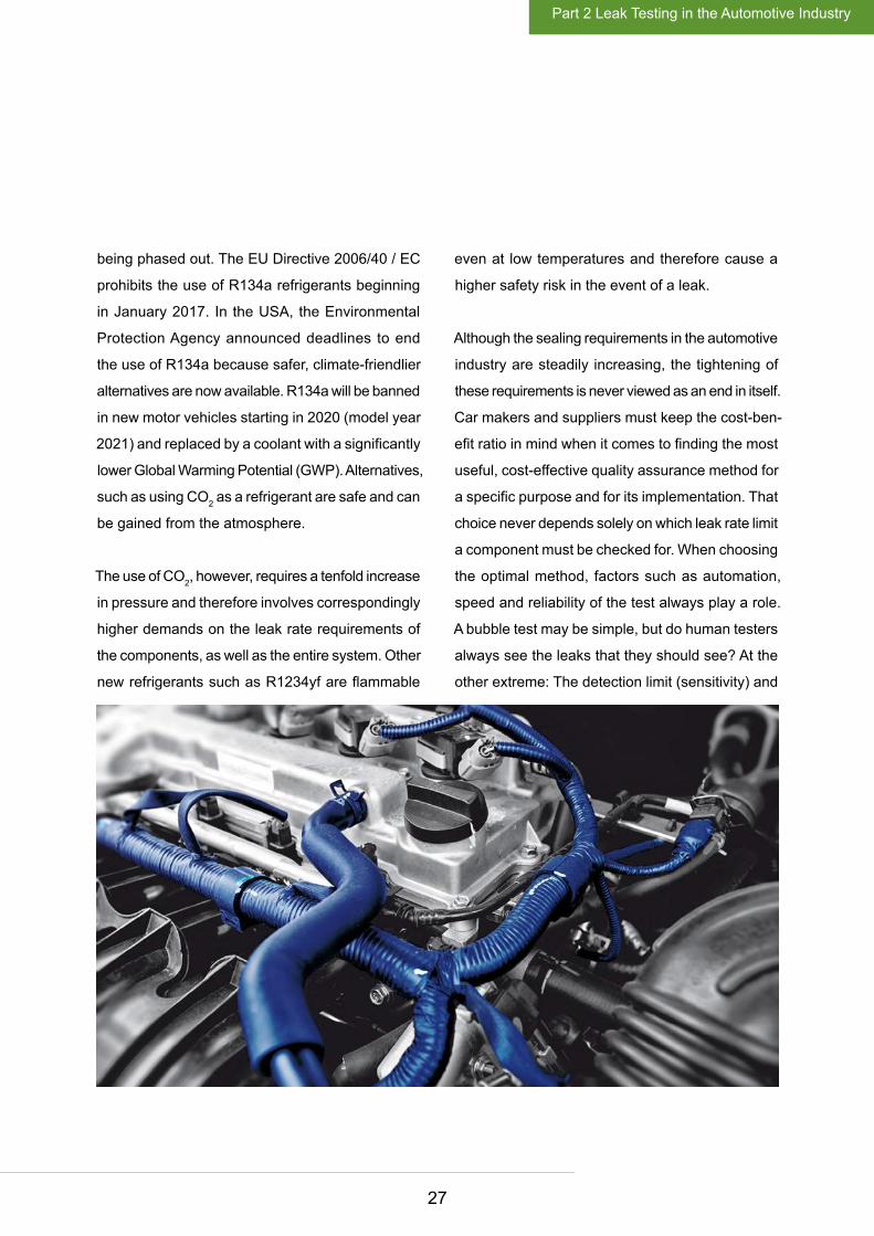
The use of CO2, however, requires a tenfold increase
in pressure and therefore involves correspondingly
higher demands on the leak rate requirements of
the components, as well as the entire system. Other
new refrigerants such as R1234yf are flammable
even at low temperatures and therefore cause a
higher safety risk in the event of a leak.
Although the sealing requirements in the automotive
industry are steadily increasing, the tightening of
these requirements is never viewed as an end in itself.
Car makers and suppliers must keep the cost-ben-
efit ratio in mind when it comes to finding the most
useful, cost-effective quality assurance method for
a specific purpose and for its implementation. That
choice never depends solely on which leak rate limit
a component must be checked for. When choosing
the optimal method, factors such as automation,
speed and reliability of the test always play a role.
A bubble test may be simple, but do human testers
always see the leaks that they should see? At the
other extreme: The detection limit (sensitivity) and
Part 2 Leak Testing in the Automotive Industry

28
the speed of automated helium testing in a vacuum
chamber are unmatched, but is this extensive and
costly effort always justified? A simpler leak test
in the accumulation chamber with special helium
sensors is often more effective and gives a better
balance between quality assurance and cost.
The choice for the optimal leak detection method is
often influenced by the human factor. Human nature
tends to lean heavily on the senses. That is another
reason why bubble tests and leak detector spray
are still used in many application scenarios where
they should have been better replaced by a tracer
gas solution. The tester wants observable evidence
and wants to see the leak. When the helium exit-
ing from a leak is measured using the tracer gas
method, it is more accurate, faster, more reliable
and reproducible than any visual check -- but the
procedure is more difficult to learn than looking for
rising air bubbles. Testers sometimes are bound by
traditional methods, even though those methods
can be quite inaccurate and misleading. Even today,
some air conditioning components are submerged
under water for testing, despite the fact that the
leak rate limit of this method is 10-3 mbar∙l/s, which
is much too high for such an application.
Part 2 Leak Testing in the Automotive Industry

29
2.2.1 Air conditioning
Beginning in 2017 in Europe and with model
year 2021 in the USA, the well-known refrigerant
R134a will be banned as a highly climate-damaging
fluorinated greenhouse gas. Replacements include
R1234yf (chemically: 2,3,3,3-tetrafluoropropene),
which, unfortunately is classified as extremely flam-
mable and also reacts when heated to form highly
corrosive hydrofluoric acid. R1234yf also is by far
more expensive than R134a. Both of those factors
are prompting manufacturers to calculate a lower
reserve of refrigerant for their systems, which in turn,
increases the leak rate requirements. R1234yf is
favored currently by car manufacturers in Asia and
the U.S. German automakers are looking at another
popular alternative: carbon dioxide (CO2).
Using CO2, however, creates quite different technical
requirements for air conditioning systems because it
is used with a significantly higher operating pressure
-- up to 120 bar. Whether the choice is R1234yf or
CO2, the leak rate requirements for air conditioning
systems and their components are rising.
2.2 Components, methods, and typical leak rates
Refrigerants are being phased out regularly and replaced by newer, more environmentally friendly substances (GWP: Global Warming Potential, ODP: Ozone Depletion Potential)
Sniffer leak detection with a manual probe detects leak rates up to 1x10⁻⁷ mbar∙l/s
Part 2 Leak Testing in the Automotive Industry

30
The old rule of thumb – a maximum leak rate of 5
grams of R134a per year will most likely be obsolete
when introducing new and future refrigerants.
A refrigerant loss of 5 grams per year corresponds
to a helium leak rate of 4x10⁻⁵ mbar∙l/s. Most air
conditioning components are currently tested for
leak rates in the order of 10-4 to 10-5 mbar∙l/s. For
air conditioning hoses, a helium test in a vacuum
chamber is used in order to achieve short cycle
times. Components such as evaporators, condens-
ers or filling valves can be tested in accumulation
or vacuum chambers. To perform a gross leak test
on air conditioning systems before filling with refrig-
erant, the pressure increase and pressure decay
methods are still widespread. However, they can
only determine large leak rates in the order of 10-2
to 10-3 mbar∙l/s.
Automakers already expect suppliers to implement
quality assurance and checks for leaks on the com-
ponent level. After the installation of the air condi-
tioning system on the assembly line, an additional
leak test on as many as three to six joints of the air
conditioning system, which have been created during
final assembly by the car manufacturer, is needed.
Automakers strive to have as few such connections
as possible, especially in more expensive vehicles
with extensive interior cladding, which limits access
to potential leak sites.
Leak testing of the junctions normally takes place
in final assembly with a sniffer leak detector. In the
past, forming gas or helium was used as a trac-
er gas, but now sniffer leak detectors can detect
the respective refrigerant and measure traces of
escaping R134a, R1234yf or CO2.
Part 2 Leak Testing in the Automotive Industry

31
2.2.2 Powertrain
For many powertrain components integral leak
testing methods are used, such as pressure decay or
differential pressure. Typical leak rates for checking
oil circuits of engine blocks or cylinder heads, for
example, are approximately 10-1 to 10-2 mbar∙l/s
(~ 12 to 1 sccm). For water circuits of engine blocks
and cylinder heads, on the other hand, it is sufficient
to have 10-1 mbar∙l/s (~ 10 sccm). Water tightness
would only be guaranteed with a limit leak rate of
about 10-3 mbar∙l/s (~ 0.05 sccm). Such leak rates,
however, often cannot be tested using the pressure
decay method.
With torque converters, the standard for the
allowable leak rate was previously 10-2 mbar∙l/s.
But given the increasingly popular and technically
demanding 9- and 10-speed automatic transmission,
future leak rates in the order of 10-3 or even
10-4 mbar∙l/s will need to be detected. Testing of a
modern, fully automatic transmission is best done
with tracer gas in the accumulation or vacuum
chamber. This also applies in charge-air coolers,
where there is a typical leak rate of 10-3 mbar∙l/s.
Here integral leak testing with helium is well-suited.
If a test piece fails the leak test, it is often still sub-
merged in water to locate the leak. With cast-iron
housings, this may still be a viable and relatively
quick method. But to submerge a modern, fully
automatic transmission worth several thousand
dollars in water and then dry and clean it again is
costly and is not the best method to locate a leak.
In addition, the bubble test method to find a leak
has a proven detection limit of only 10-2 mbar∙l/s,
which is a hundred to a thousand times worse than
the leak rate that was detected in the previous leak
test. Using a sniffer leak detector and tracer gases,
such as helium or forming gases, are preferable in
this situation, particularly because a water bath
always bears the risk of rust and damage to elec-
trical components.
In many cases, a test tank is still used simply because
no one has reviewed the choice of the leak testing
method. But as a general rule of thumb: the larger
the test piece, the more often the soap spray test is
used instead of the bubble test. For engine blocks,
leaks are often localized using leak detector spray,
but the subsequent drying and cleaning effort is still
unavoidable. Sniffer leak detection using tracer gas
is cleaner, more efficient and more accurate.
For engines, sniffer leak detection using tracer gas is cleaner, more efficient and more accurate than leak testing spray
Part 2 Leak Testing in the Automotive Industry
32
2.2.3 Fuel systems
For a number of fuel system components the in-
tegral leak test with helium in the accumulation
chamber is a good choice. The leak rates limits
for modern injectors today are in the range of 10-4
to 10-5 mbar∙l/s. The leak rate test for gas pumps
today is in the order of 10-4 mbar∙l/s. Because of the
particularly high operating pressures, common rail
injectors often have higher leak rate requirements
-- between 10-4 to 10-6 mbar∙l/s. Less demanding are
diesel filters, which often only need to be tested to
a leak rate of about 10-2 mbar∙l/s.
Generally for fuel systems, fuel tanks and fuel lines
there are higher leak rate requirements. This is
motivated by the need to meet stricter U.S., and
especially California, regulations for preventing
hydrocarbon emissions. This also makes the use
of permeable plastics particularly problematic.
Fuel tanks and fuel lines today are tested by many
manufacturers against leak rates up to 10-4 to 10-6
mbar∙l/s. This excludes the use of bubble tests or
pressure decay and differential pressure tests. Such
a leak limit rates can only be detected by integral
leak testing with tracer gases. For smaller parts
such as injectors or motorcycle tanks, the test in the
accumulation chamber is ideal. Because the detec-
tion limit of the accumulation method is dependent
on the free volume of the test chamber, very large
parts are tested by the vacuum method.
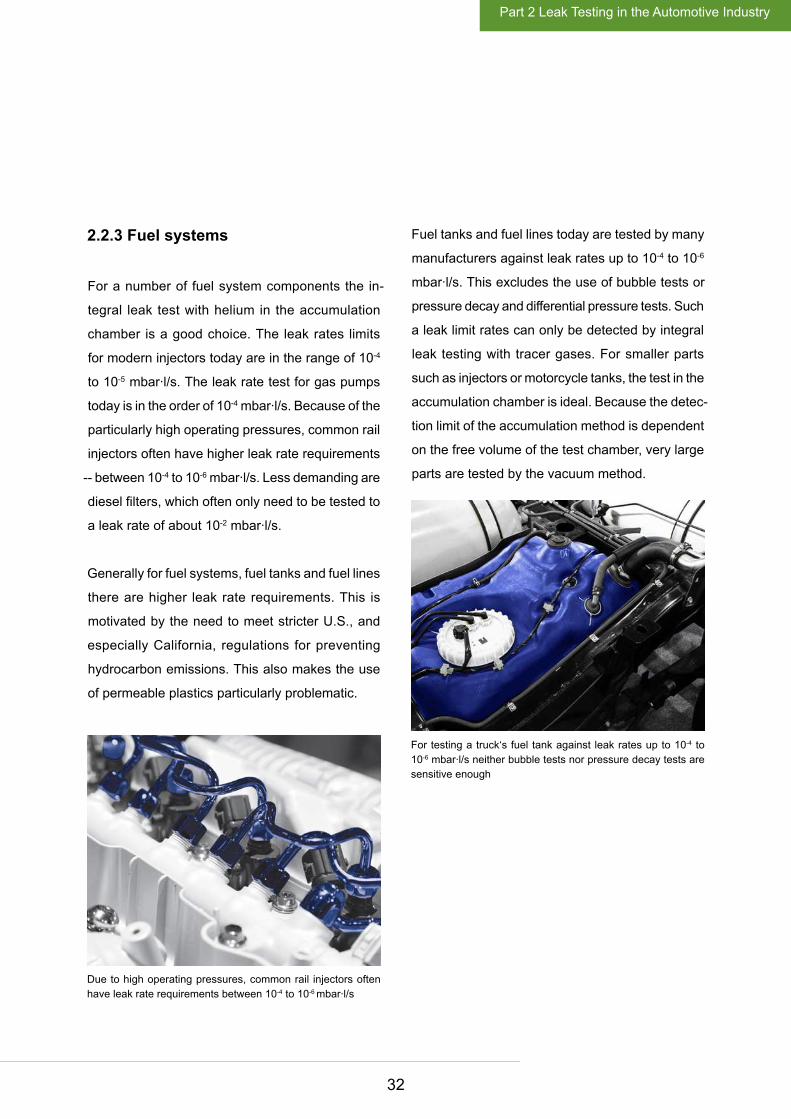
Due to high operating pressures, common rail injectors often have leak rate requirements between 10-4 to 10-6 mbar∙l/s
For testing a truck‘s fuel tank against leak rates up to 10-4 to 10-6 mbar∙l/s neither bubble tests nor pressure decay tests are sensitive enough
Part 2 Leak Testing in the Automotive Industry

33
2.2.4 Oil and water circuits
The most stringent leak rate requirements for oil
and water circuits of the vehicle are for the oil cooler
that removes heat from the oil for better lubrication.
These tighter requirements are in place so that the
oil and water do not mix, preventing costly engine
damage. Typical leak rates are 10-2 to 10-4 mbar∙l/s,
and the cost-effective accumulation chamber is rec-
ommended. Similarly, demands are high on a vehi-
cle’s plastic oil tank, which is usually tested against
leak rates of 10-3 mbar∙l/s in the vacuum chamber
for efficiency reasons. Testing via pressure decay or
differential pressure methods do not work well here
because of the natural deformability of the plastic
material, which can skew the results considerably.
Other components such as oil pans and oil pumps
are often tested against leak rates of 10-2 mbar∙l/s.
On the one hand, leak testing is needed to guarantee
that no oil escapes from the circuit, but making sure
that no water from the cooling circuit enters the oil
circuit is also critically important.
In water pumps and radiators the leak rate may
often not exceed a leak rate of 10-2 mbar∙l/s. With
radiators, bubble testing is still quite common. The
bubble test is insufficient with a radiator casting
that has a fine ribbed structure. Bubbles may form,
but because they cannot detach themselves from
the test piece, the human tester cannot perceive
them. Here tracer gas methods are more reliable.
The pressure decay method also is not suitable
for radiators. Because of its very composition, a
radiator is susceptible to temperature variations,
and the pressure decay measurement would be
seriously inaccurate.
In a water bath test, bubbles may not be able to detach from a water cooler‘s fine ribbed structure
Part 2 Leak Testing in the Automotive Industry

34
2.2.5 Safety features
For all directly safety-related components in a
vehicle, the demand for tightness is naturally quite
high. For brake hoses, brake fluid reservoirs and
brake boosters, the typical allowable leak rate is in
the order of 10-3 to 10-4 mbar∙l/s. In this case a helium
test in the accumulation chamber is recommended.
Airbag gas generators have come into the news
recently because of significant vehicle recalls. To
prevent moisture entering the pyrotechnic gas
generator, tests today are mostly to a leak rate of
10-6 mbar∙l/s. Often the bombing method is used.
In these tests the igniter is first exposed in a pres-
sure chamber with helium overpressure so that the
tracer gas enters the test piece through leaks. Then,
the igniter is put into a vacuum chamber. After the
evacuation of the vacuum chamber, the helium in
the test piece can leak into the chamber, where it
is measured by mass spectrometry.
The leak rate requirements for cold gas generators
for airbags are slightly higher. Cold gas generators
are usually filled with a helium-argon mixture. In
order for this gas mixture to inflate the airbag when
discharged, it is under high pressure. This pressure
must be maintained for at least 10 years – with some
manufacturers looking for 15 to 17 years. Hence,
the tightness of cold gas generators is tested in
the vacuum chamber, often against a leak rate of
10-7 mbar∙l/s.
Using the bombing method, airbag ignitors are tested against a leak rate of 10-6 mbar∙l/s
Part 2 Leak Testing in the Automotive Industry

35
2.2.6 Wheel rims, shock absorbers and other components
Even with aluminum rims, tightness plays an
important role for wheels. This is true for more ex-
pensive alloy wheels, which are usually two parts
welded together, as well as for the simpler, cast
lightweight wheel rims. In cast wheel rims, it is
important to make sure there are no porosity leaks
so that tubeless tires will not lose air through the
porosity in the wheel rim. Modern wheel rims are
often tested in the vacuum chamber to a leak rate
of about 10-4 mbar∙l/s.
The same method with the same typical leak rate is
used for the integral leak testing of shock absorbers.
For servo oil tanks and the power steering housing,
the helium test in the accumulation chamber is a
good solution. The leak rates here are usually in
the order of 10-2 to 10-4 mbar∙l/s.
For integral leak testing of batteries, the accumula-
tion chamber also is a good choice. The leak rate
that a car battery may not exceed when tested is
usually in the region of 10-3 mbar∙l/s. Batteries are
currently often tested using the pressure decay
method, but face the problem of deformability of
the plastic housing.
Part 2 Leak Testing in the Automotive Industry
Modern wheel rims are often tested in the vacuum chamber to a leak rate of 10-4 mbar∙l/s

36
37
Error 1: Using the wrong method for the test leak rate
Often the bubble test method produces the wrong
results. If the tester does not see any bubbles, then,
it is assumed there is no leak. The tester believes
what he does not see and is satisfied.
A basic condition for determining whether a leak test
or leak detection method for a particular applica-
tion is suitable is its leak rate. It is interesting how
often this simple rule is violated. Plastic parts are
tested using the pressure decay method without
considering their deformability and the change in
volume due to the compressed air. Also, the leak
rate of an integral leak test and subsequent leak
detection have to work together. Sometimes the
integral leak test is carried out in the helium chamber,
but the subsequent localization of leaks is carried
out using the bubble test method instead of using
the more precise sniffer leak detection method with
tracer gas.
Error 2: The wrong point in time in the production process is chosen for testing
It is important to think twice about selecting the
best point in the production process to perform a
leak test. It often makes sense to test individual
subcomponents for leaks prior to assembly. For
example, it is a very good idea to check the tightness
of a transmission case before the transmission is
assembled because if the housing fails in the final
test and must be ejected, all of the work of assem-
bling the transmission is lost.
2.3 Ten most common errors in leak testing
Part 2 Leak Testing in the Automotive Industry

38
Error 3: The test piece is already contaminated
Generally, for all test methods the following should
apply: The leak test or the leak detection always
should take place on new, unused test pieces. If a
component has already been in operation or has
been filled with oil or water, the danger is great that
small leaks have already clogged. It is possible that
compressed air or tracer gas can then possibly no
longer escape from the test piece (or enter it).
On castings, sometimes cutting-oil residues are
found after the machining process. Before a leak
test takes place, the test piece must first be cleaned.
After cleaning, the part must then be dried again,
which also insures that the cleaning fluid does not
clog potential leaks in the short term.
Error 4: Temperature changes are ignored
Temperature fluctuations represent a serious problem
especially for integral leak tests using pressure decay
or differential pressure measurement. Even small
temperature fluctuations can change the measurable
leak rate by several orders of magnitude. The size of
a leak also is influenced by a temperature increase
and the expansion behavior of the material to be
tested. In an exhaust gas cooler, in some cases leaks
only occur when it has reached its typical operating
temperature. Some manufacturers therefore carry
out type testing in climatic chambers.
Part 2 Leak Testing in the Automotive Industry

39
Error 5: The test pressure fluctuates
To be able to determine leak rates reliably and
reproducibly, it is critical, even when using tracer
gas methods, to always fill the test piece at the
same constant pressure. Automated tracer gas
filling systems guarantee this. But be careful. With
some test pieces the correct filling is only possible
after a prior evacuation. Heat exchangers usually
consist of long, snakelike tube systems. If you fill a
tracer gas here, you can increase the pressure in
the test piece, but only after a previous evacuation
can you ensure that the tracer gas reaches every
possible leak. In addition, especially with the helium
tracer gas test, the concentration of the tracer gas
may be reduced to save on testing costs. Some
tests are performed with a helium content of only
1% -- which means that the proper distribution of
the tracer gas is even more important.
Error 6: Filling with tracer gas withoutprevious evacuation
For proper leak testing it is absolutely mandatory to
evacuate the test piece before filling with tracer gas.
This is particularly important for long and narrow
geometries. If you do not evacuate before filling, the
air in the test piece will simply be pushed to the end
of the geometry and no tracer gas will get to this
area, hence potential leaks will only release air and
cannot be detected by your tracer gas leak detector.
Evacuation is also especially important if you fill
the part to be tested with low pressures of tracer
gas only as the left-in air will dilute the tracer gas
filled in. Example: If the piece is filled with air at at-
mospheric pressure and you add one atmosphere of
tracer gas, the tracer gas concentration in the piece
is only 50%. If you add two atmospheres of tracer
gas, the concentration of tracer gas will be 66%.
Part 2 Leak Testing in the Automotive Industry

40
Error 7: The testers do not know what they are actually measuring
Using a reproducible measurement method as an
integral leak test, rather than to continue to rely on
the mere perception of a human tester is a big step
in the right direction. It is important to know what
you are actually measuring and which test medium
is being used. Occasionally leak rates are specified
for air, but helium has a slightly higher dynamic
viscosity than air. If the leak rate is specified for air
but helium is being used, proper conversion data
must be used to provide a more precise leak rate.
If you want to measure the leak rate in grams per
year of an air conditioning unit with an integral leak
test (escaping mass per year) keep in mind that the
helium measuring instrument used for the test may
under certain circumstances, indicate a volume flow
of helium in mbar∙l/s
There are devices that perform an automatic con-
version, such as the Protec P3000(XL). The exact
conversion factors of these units result from the
different molecular weights of the refrigerant. If, for
cost reasons, testing is done with diluted helium
mixtures, the helium concentrations that can be
measured are different. This must be taken into
account when interpreting the leak rate results.
Moreover, tightness requirements always apply to
a specific operating pressure. The pressure that is
used for the test often deviates. It may be higher or
lower than the later operating pressure of the test
piece, which also makes a proper conversion of the
leak rate necessary.
It also would be a serious mistake to equate a leak
rate with a concentration of gas that is indicated
on some instruments as parts per million (ppm).
The concentration is a snapshot; it only indicates
how many particles are in a given space at a given
moment. The leak rate indicates, however, the size
of the volume flow through a leak.
Part 2 Leak Testing in the Automotive Industry
41
Error 8: Stringer leaks and gross leaks are underestimated
Stringer leaks consisting of capillary-like corridors
can seriously affect airbag manufacturers. It is im-
portant to consider how long it takes for the helium
tracer gas to distribute so that it also emerges from
these stringer leaks. If you work with very short
times between filling and testing, it is difficult or
even impossible to identify stringer leaks. Another
example: Even on cable feedthroughs there might
be leak channels several centimeters in length. It
may take several minutes for the tracer gas to leak
out of them.
The opposite of a stringer leak is a gross leak. In a
gross leak the helium escapes from the test piece
before the actual test interval. In effect, you evacuate
the vacuum test chamber and the helium from the
test piece at the same time. Sometimes a simple
pressure decay test is integrated into the tracer gas
system to identify any gross leaks before filling the
test piece with helium.
Error 9: Maintenance of the test system is neglected
If no leak rates are measured on a test station for
days or weeks, it could mean one of two things;
either the quality of the production is superb, or the
test system is functioning inadequately. Sometimes
there are leaking tracer gas lines that prevent correct
measurement in the test chamber. All interconnect
points, hoses, test piece brackets, etc., must be
checked regularly. Sometimes the tracer gas sys-
tems are extensively and inexpertly repaired. If an
interconnect point is wrapped in TeflonTM tape, in
the hope that the connection is sealed, this is most
definitely a mistake. Helium gas will always escape
through the porous Teflon tape, causing accuracy
and cost problems.
Sometimes, errors in a test setup can be identified
by regularly checking the functioning and accuracy
of the system by using a reference leak that, due
to its defined size, is always the same leak rate. If
this leak rate is not determined during the test, the
system has inaccuracies. It is best to opt for a test
leak in the form of a glass capillary. For less de-
manding test leaks, metal is squeezed to a narrow
point. These test leaks will vary in leak rate greatly
depending on temperature and pressure -- glass
capillaries are therefore better for this purpose.
A regular check of the system with a calibration
Part 2 Leak Testing in the Automotive Industry

42
leak prevents sometimes other, very fundamental
problems. For example testers have mistakenly
connected an oxygen bottle instead of a helium
bottle to their system.
Error 10: We can do it ourselves
Maybe, but think about it carefully. When it comes
to industrial leak testing and leak detection, it is
important to consult with experts and get advice.
It is critically important to choose the appropriate test
method for a specific application, to configure the
system correctly, and to make the review process as
foolproof and reliable as possible -- certainly not a
trivial task. Again, seek professional support. If you
want to ensure the quality of your production and
avoid costly product recalls, it is not enough to simply
say, „yes, we do check something.” A negative test
is no guarantee that a test piece actually meets the
requirements set. You can only have this guarantee
if your test methods and processes work reliably.
The challenge is to do the right measurement and
in the right way, every day and at every level.
Part 2 Leak Testing in the Automotive Industry

43
Appendix

44
3.1.1 Videos
Robotic leak testing on GDI engines Leak location on engine in rework
Leak testing of evaporators for car A/C with
T-Guard
Leak testing of car A/C hoses
3.1 Web links
Appendix

45
3.1.2 Description of leak testing applications
• Leak testing of transmissions
• Leak testing of plastic containers
• Leak testing of fuel injectors
• Leak testing of heat exchangers
• Leak testing of airbag gas generators
• Leak testing of fuel and DEF tanks
• Leak testing of fuel rails
• Leak testing of wheel rims
Appendix

46
3.2 Source of illustrations
title: Shutterstock © Philip Lange
title: Shutterstock © masuti
title: Shutterstock © Vladimiroquai
p. 7: Shutterstock © junron
p. 8: INFICON
p. 10: INFICON
p. 20: INFICON
p. 25: Shutterstock © Philip Lange
p. 26: INFICON
p. 27: Shutterstock © Snw
p. 29: Shutterstock © Thailand Travel and Stock
p. 31: INFICON
p. 32: Fotsearch © csp_Reeed
p. 32: Shutterstock © Philip Lange
p. 33: Shutterstock © masuti
p. 34: Shutterstock © hxdbzxy
p. 35: Shutterstock © Vladimiroquai
p. 47: INFICON
p. 52: INFICON
Appendix

47
3.3 About INFICON
INFICON is one of the leading companies when it comes to development, production and sales of instruments
and devices for leak testing. INFICON leak testing equipment is used in demanding industrial processes
in production and quality control. INFICON leak detectors cover a wide variety of leak testing applications.
Main customers of INFICON are manufacturers as well as service companies for the RAC industry, the
automotive industry, the semiconductor industry and manufacturers of leak testing systems. Almost all
automotive manufacturers and their suppliers are INFICON customers. INFICON technology helps testing
airbags, car air conditioners and their components, fuel systems and all types of fluid containers.
(www.inficonautomotive.com).
For more information about INFICON, visit us at www.inficon.com.
Appendix
INFICON production facility in Syracuse, NY – development, design and manufacturing of leak detection service tools
INFICON production facility in Köln, Germany – development, design and manufacturing of leak testing production tools
48
3.4 References
3.4.1 Manufacturers of passenger cars
Adam Opel AG
Alfa Romeo
Audi
Bentley Motor Cars
BMW
Brilliance Jinbei
Bugatti
BYD
Changan Automobile
Chrysler
Daewoo Tata
Daimler
Dongfeng Motor
Ferrari
Fiat Chrysler
Ford
Foton Motor
Geely
General Motors
Great Wall Motor
Honda
Hyundai
Isuzu
Jaguar
Kawasaki
Kia
Land Rover
Maserati
Mazda
Mercedes-Benz
Mitsubishi Motors
Nissan
OAO ZMA (Sollers ZMA)
Peugeot Citroën Automobiles
Porsche AG
Qoros Motors
Renault
Rolls-Royce Motor Cars
Rover
Saab
Seat
Skoda Auto
Toyota Motor
Volkswagen
Volvo
Wuling Motors
3.4.2 Manufacturers of heavy duty vehicles
Bobcat
Caterpillar
Claas
Evobus
IVECO
John Deere
Liebherr Baumaschinen
MACK Trucks
MAN
Motor Coach Industries
Scania
Appendix

49
3.4.3 Automotive component suppliers
ABC Group Fuel Systems, Inc.
Aeroquip
Alcoa Wheels
Allgaier Automotive
Allison Transmission
ARC Automotive (Atlantic Research Corporation)
Autoclima
Autoliv
Behr
Benteler Automobiltechnik
Bergstrom Climate Systems
Bertrandt
Borbet
Borg Warner
Brunel Car Synergies
Calsonic Kansei
Central Motor Wheel of America
Chaoli Hi-Tech
Cinetic Automation
Clean Energy
Coclisa
Cognis
Continental Automotive
ContiTech
Cummins Inc.
Dare Wheel Manufacturing
Dayco
Delphi Automotive
Denso
Deutsche ACCUmotive
Deutz AG
Dicastal Weel
Dominion Technology
Dürr Somac
Durr Systems
Eaton
Eberspächer
EDAG
ElringKlinger
Federal Mogul
Flextronics Automotive
FTS
Frankling Precision Industry
Freudenberg
Fuel Cell Energy
FuelCon
Fuel-Tec
Getrag
GLS Automotive
Grammer
Griffin Thermal Products
Halla Climate Control
Halla Visteon
Hayes Lemmerz Alukola
Hella KG
Hengst
Hirschvogel
Honeywell
H S Automotive
Hutchinson (SNC)
INERGY Automotive Systems
Ingersoll Rand
IPETRONIK
ixetic
Appendix

50
Johnson Controls
Kautex
Kayser Automotive System
KB Autotech
Keihin
KEPICO
Key Safety Systems
Köhler Automobiltechnik
Kostal
KTM Kühler
Landi Renzo
Leonardo
Lovato Gas
LuK Fahrzeug-Hydraulik
Magna
Magnetti Marelli
Mahle
Mammoth Air Conditioning
Mangels
Mann + Hummel
Manuli Auto
Martinrea Industries
MCS Cylinder Systems
Mecachrome
Michigan Automotive Compressor
Microflex Automotive
Mobile Climate Control
Modine
Motion Industrie
MTU
Navistar
NHK
Nichirin
NOK
NuCellSys
Parker Hannifin
Perkins Motors
Philips Automobile Lightning
Robert Bosch
Sanden Behr Automotive
Sanden Manufacturing
Sanhua Automobile
Schrader
Senstar Automotive
SMA Metalltechnik
Takata
TI Automotive
Tokyo Industries
Tokyo Radiator
Topvalue Global
Topy America, Inc.
TRW Vehicle Safety Systems
Valeo
Valeo Fawer Compressor
VDO Siemens
Vibracoustic
Visteon
Zexel Valeo Compressor
Appendix
51
3.5 Contact information
INFICON
Two Technology Place
East Syracuse, New York 13057
USA
Phone (315) 434-1100
Email: [email protected]
Internet: www.inficonautomotive.com
mika00en-a (1603) © 2016 INFICON
Appendix
INFICON employee in Cologne, helping customers on the phone