leaky buddies: cross-component covert channels on
TRANSCRIPT
Leaky Buddies: Cross-Component Covert Channelson Integrated CPU-GPU Systems
Sankha Baran DuttaDepartment of CSE
University of California, RiversideRiverside, California, USA
Hoda NaghibijouybariDepartment of Computer Science
Binghamton UniversityBinghamton, New York, USA
Nael Abu-GhazalehDepartment of CSE
University of California, RiversideRiverside, California, USA
Andres MarquezPacific Northwest National Laboratory
Richland, WA, [email protected]
Kevin BarkerPacific Northwest National Laboratory
Richland, WA, [email protected]
Abstract—Graphics Processing Units (GPUs) are a ubiquitouscomponent across the range of today’s computing platforms,from phones and tablets, through personal computers, to high-end server class platforms. With the increasing importance ofgraphics and video workloads, recent processors are shipped withGPU devices that are integrated on the same chip. IntegratedGPUs share some resources with the CPU and as a result,there is a potential for microarchitectural attacks from theGPU to the CPU or vice versa. We believe this type of attack,crossing the component boundary (GPU to CPU or vice versa)is novel, introducing unique challenges, but also providing theattacker with new capabilities that must be considered whenwe design defenses against microarchitectrual attacks in theseenvironments. Specifically, we consider the potential for covertchannel attacks that arise either from shared microarchitecturalcomponents (such as caches) or through shared contentiondomains (e.g., shared buses). We illustrate these two types ofchannels by developing two reliable covert channel attacks.The first covert channel uses the shared LLC cache in Intel’sintegrated GPU architectures. The second is a contention basedchannel targeting the ring bus connecting the CPU and GPUto the LLC. Cross component channels introduce a number ofnew challenges that we had to overcome since they occur acrossheterogeneous components that use different computation modelsand are interconnected using asymmetric memory hierarchies.We also exploit GPU parallelism to increase the bandwidth ofthe communication, even without relying on a common clock. TheLLC based channel achieves a bandwidth of 120 kbps with a lowerror rate of 2%, while the contention based channel delivers upto 400 kbps with a 0.8% error rate.
I. INTRODUCTION
In recent years, micro-architectural covert and side channelattacks have been widely studied on modern CPUs, exploitingoptimization techniques and structures to exfiltrate sensitiveinformation. A preponderance of these studies exploit CPUstructures examining channels through a variety of contentiondomains including caches [25], [30], [37], [41], [46], branchpredictors [9], random number generators [8], and others [5],[26]. Modern computing systems are increasingly heteroge-neous, consisting of a federation of the CPU with GPUs,NPUs, other specialized accelerators, as well as memory and
storage components, using a rich interconnect. It is essentialto understand how micro-architectural attacks manifest withinsuch complex environments (i.e., beyond just the CPU).
We consider a new type of attack which we term cross-component attacks. In these attacks, the attacker resides on acomponent within a heterogeneous system (e.g., an accelerator)and launches an attack on a victim executing on anothercomponent (e.g., the CPU, or another accelerator). We explorethe principles of such attacks by exploring covert channelattacks within integrated GPU (iGPU) systems, where a GPUis built on the same die as the main CPUs, exploring covertchannel attacks originating from the GPU to the CPU or viceversa. iGPUs are integrated with consumer class CPUs usedin desktops and laptops, and also extensively used in portableelectronic devices such as tablets and smart phones to providegraphics, compute, media, and display capabilities. Moreover,iGPUs exemplify a trend to gradually increase the level ofheterogeneity in modern computing systems, as further scalingof fabrication technologies allows formerly discrete componentsto become integrated parts of a system-on-chip, and provides forintegration of specialized hardware accelerators for importantworkloads. Understanding microarchitectural vulnerabilities insuch environments is essential to the security of these widelyused systems, as well as to illuminate potential threats togeneral heterogeneous computing systems.
Although covert channels have been demonstarted on avariety of CPU structures, as well as on discrete GPUs [22],[23], [34], [35], we believe our attacks are significantly differentfrom prior work because they operate across heterogeneouscomponents. Specifically, to the best of our knowledge, allprior demonstrated covert channels are symmetric, with boththe sender and receiver being identical: typically threads orprocesses access a resource that they use to create contention.In contrast, cross-component attacks occur between two entitiesthat can have substantially different computational models, andthat share asymmetric access to resources. As a result, theattacks necessitate careful reverse engineering of asymmetric
1
arX
iv:2
011.
0964
2v1
[cs
.CR
] 1
9 N
ov 2
020
views of the resource from both side, and understanding ofhow contention occurs between them across a complex inter-connected architecture. Moreover, we believe this is the firstattack demonstrated on heterogeneous environments, providingimportant insights into how this threat model manifests in suchsystems, and extend our understanding of the threat modeland guide further research into defenses. It is also importantto note that successfully creating a covert channel establishesthe presence of leakage and is a pre-requisite indicator of thepotential presence of the more dangerous side channels, whichwe will explore in future.
An iGPU is tightly integrated on the same die with the CPUand shares resources such as the last level cache and memorysubsystem with it, in contrast to discrete GPUs which have adedicated graphics memory. This integration opens up the po-tential of new attacks that exploit the use of common resourcesto create interference between these components, leading tocross-component micro-architectural attacks. Specifically, wedevelop covert channels (secret communication channels thatexploit contention) on integrated heterogeneous systems inwhich two malicious applications, located on two differentcomponents (CPU and iGPU) transfer secret information viashared hardware resources. In order to develop this new typeof channels, we had to solve a number of new challengesrelating to synchronization across heterogeneous componentswith frequency disparity, reconciling different computationalmodels and memory hierarchies, and creating reliable fine-grained timing mechanisms, as well as others. Successfullydemonstrating these channels highlights the possibility ofmore dangerous side-channel attacks (the presence of a covertchannel is a prerequisite for side-channel attacks), as well asproviding concrete examples that illuminate the principles forgeneral cross component attacks in heterogeneous systems,expanding our understanding of microarchitectural attacks toguide the development of mitigation strategies in such importantsystems.
Section II provides an overview of the integrated CPU-GPUsystems architecture and our threat model. We consider twopossibilities for creating covert channels in cross componentsystems: (1) Contention through directly shared microarchi-tecture resources. In the case of the integrated CPU-GPUsystem we use in our experiments, the lowest level of thecache (the LLC) is shared and serves as our example of thistype of channel; and (2) Contention through time multiplexedresources such as shared buses, cache ports, computational unitsand similar resources. In such resources, if both componentsuse the resource at the same time, there is a perceived delayas their requests contend for the use of the limited resource.We illustrate this type of channel by building a covert channelattack on the ring-bus interconnect the CPU and GPU to theLLC cache. We believe another channel type may exist ifthere are interaction protocols among the components (e.g., forcoherence) but we leave exploration of such channels to futurework.
The first attack (described in Section III) is aPRIME+PROBE based covert channel on the shared Last
Level Cache (LLC). Developing this attack requires reverseengineering of the partially documented GPU L3 cachearchitecture and its interaction with the LLC. Since the GPUcache hierarchy is attached to the CPU hierarchy at the LLClevel, we had to work around substantial differences of thecache view including: (1) the index hashing in the GPU L3 isnot consistent with the index hashing of the shared LLC: theconflict set addresses to overflow the GPU L3 to cause an LLCaccess do not hash to the same LLC set, causing a substantialself-interference problem which we mitigated; (2) the LLC isinclusive on the CPU side, but not on the GPU side limitingsome attack strategies; and (3) we had to calibrate the twosides to overcome the disparity of low GPU frequency and highCPU frequency and enable reliable high-quality communication.Another challenge we had to address is the lack of a GPUhardware timer available to time the difference between cachehits and misses: we developed a custom timer using a kernel thatincrements a shared variable atomically. The second attack wepresent creates contention among resources due to simultaneousaccess by CPU and GPU (Section IV), which also required usto characterize the contention behavior to build reliable andsynchronized contention. The bandwidth and error obtainedfrom the two channels are presented in section V. The LLCbased channel achieves a bandwidth of 120 kbps with an errorrate of 2% while the contention based channel achieves abandwidth of 400 kbps with a 0.8% error rate. We discuss thepotential mitigations in Section VI and compare our work toother related attacks in Section VII.
In summary, the contributions of this paper are:• We present a new class of attacks that span different
components within a heterogeneous systems.• We reverse engineer several components on integrated
CPU-GPU system, and develop solutions to challengesrelating to cross-component channels.
• We illustrate these attacks by building and characterizingtwo real covert channel attacks on an integrated CPU-GPUsystem.
In addition, we believe that these channels provide a valuablefirst experience with these types of channels which must beconsidered in the design of secure heterogeneous systems.Section VIII discusses possible future research and presentsour concluding remarks.
II. BACKGROUND AND THREAT MODEL
In this section, we introduce the organization of Intel’sintegrated GPU systems, to provide background necessaryto understand our attack. We also present the threat model,outlining our assumptions on the attacker’s capabilities.
A. Intel Integrated CPU-GPU systems
Traditionally, discrete GPUs are connected with the rest ofthe system through PCIe bus, and have access to a separatephysical memory (and therefore memory hierarchy) than thatof the CPU. However, starting with Intel’s Westemere in 2010,Intel’s CPUs have integrated GPUs (iGPU, called IronlakeGraphics) incorporated on the same die with the conventional
2
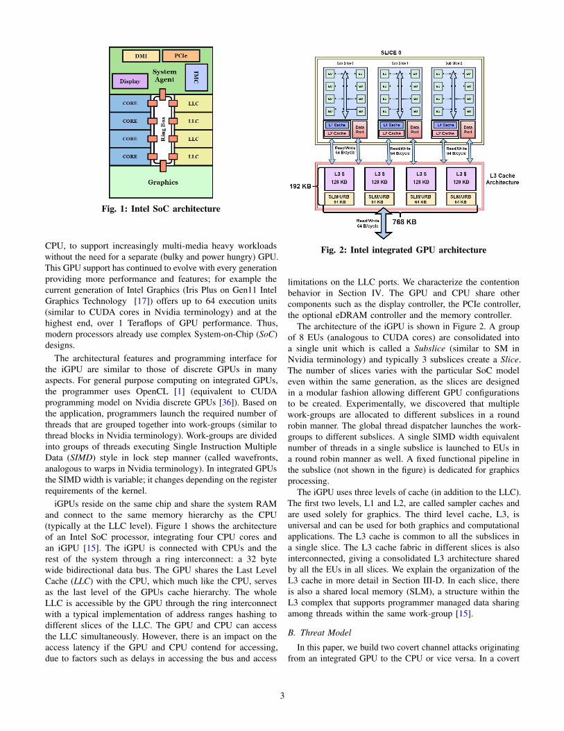
Fig. 1: Intel SoC architecture
CPU, to support increasingly multi-media heavy workloadswithout the need for a separate (bulky and power hungry) GPU.This GPU support has continued to evolve with every generationproviding more performance and features; for example thecurrent generation of Intel Graphics (Iris Plus on Gen11 IntelGraphics Technology [17]) offers up to 64 execution units(similar to CUDA cores in Nvidia terminology) and at thehighest end, over 1 Teraflops of GPU performance. Thus,modern processors already use complex System-on-Chip (SoC)designs.
The architectural features and programming interface forthe iGPU are similar to those of discrete GPUs in manyaspects. For general purpose computing on integrated GPUs,the programmer uses OpenCL [1] (equivalent to CUDAprogramming model on Nvidia discrete GPUs [36]). Based onthe application, programmers launch the required number ofthreads that are grouped together into work-groups (similar tothread blocks in Nvidia terminology). Work-groups are dividedinto groups of threads executing Single Instruction MultipleData (SIMD) style in lock step manner (called wavefronts,analogous to warps in Nvidia terminology). In integrated GPUsthe SIMD width is variable; it changes depending on the registerrequirements of the kernel.
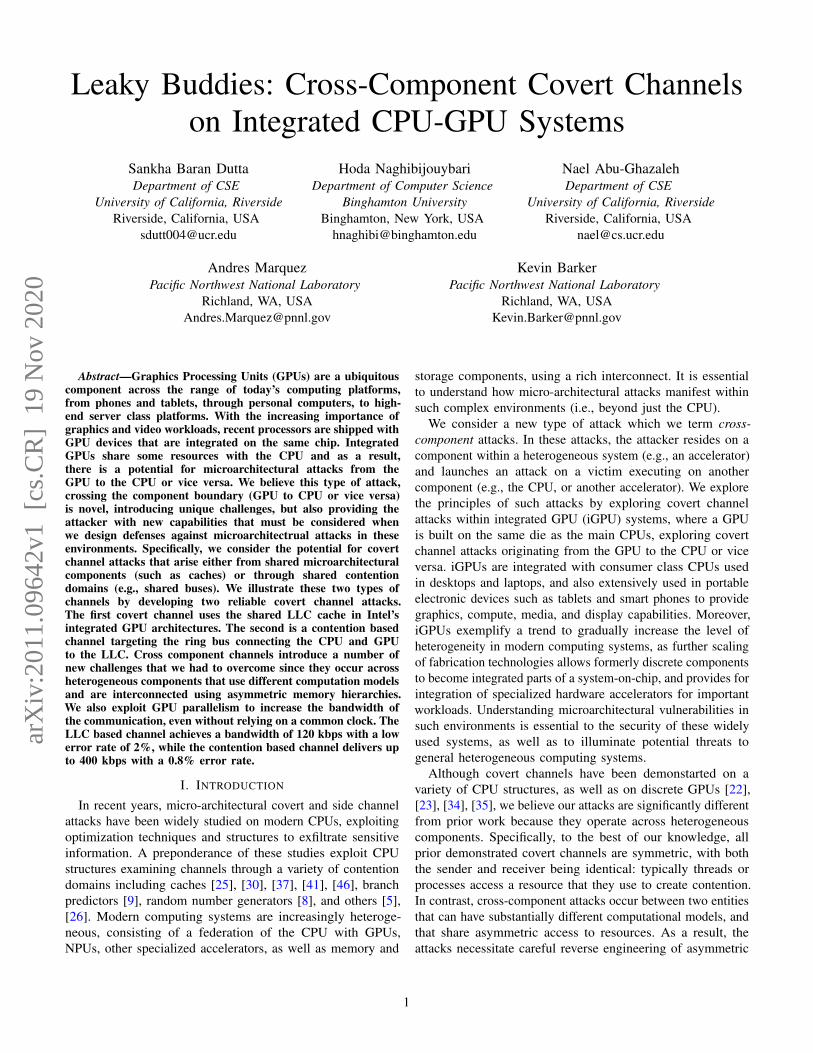
iGPUs reside on the same chip and share the system RAMand connect to the same memory hierarchy as the CPU(typically at the LLC level). Figure 1 shows the architectureof an Intel SoC processor, integrating four CPU cores andan iGPU [15]. The iGPU is connected with CPUs and therest of the system through a ring interconnect: a 32 bytewide bidirectional data bus. The GPU shares the Last LevelCache (LLC) with the CPU, which much like the CPU, servesas the last level of the GPUs cache hierarchy. The wholeLLC is accessible by the GPU through the ring interconnectwith a typical implementation of address ranges hashing todifferent slices of the LLC. The GPU and CPU can accessthe LLC simultaneously. However, there is an impact on theaccess latency if the GPU and CPU contend for accessing,due to factors such as delays in accessing the bus and access
Fig. 2: Intel integrated GPU architecture
limitations on the LLC ports. We characterize the contentionbehavior in Section IV. The GPU and CPU share othercomponents such as the display controller, the PCIe controller,the optional eDRAM controller and the memory controller.
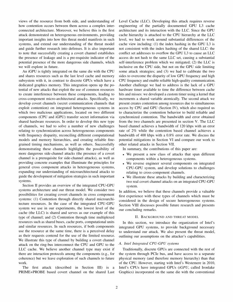
The architecture of the iGPU is shown in Figure 2. A groupof 8 EUs (analogous to CUDA cores) are consolidated intoa single unit which is called a Subslice (similar to SM inNvidia terminology) and typically 3 subslices create a Slice.The number of slices varies with the particular SoC modeleven within the same generation, as the slices are designedin a modular fashion allowing different GPU configurationsto be created. Experimentally, we discovered that multiplework-groups are allocated to different subslices in a roundrobin manner. The global thread dispatcher launches the work-groups to different subslices. A single SIMD width equivalentnumber of threads in a single subslice is launched to EUs ina round robin manner as well. A fixed functional pipeline inthe subslice (not shown in the figure) is dedicated for graphicsprocessing.
The iGPU uses three levels of cache (in addition to the LLC).The first two levels, L1 and L2, are called sampler caches andare used solely for graphics. The third level cache, L3, isuniversal and can be used for both graphics and computationalapplications. The L3 cache is common to all the subslices ina single slice. The L3 cache fabric in different slices is alsointerconnected, giving a consolidated L3 architecture sharedby all the EUs in all slices. We explain the organization of theL3 cache in more detail in Section III-D. In each slice, thereis also a shared local memory (SLM), a structure within theL3 complex that supports programmer managed data sharingamong threads within the same work-group [15].
B. Threat Model
In this paper, we build two covert channel attacks originatingfrom an integrated GPU to the CPU or vice versa. In a covert
3
channel, two distinct processes communicate covertly over acommunication channel. The sending process is known as theTrojan, while the receiving process is called the Spy. To thebest of our knowledge, previously established covert channelswere within the same physical device, either a CPU [33] orGPU [34], but not spanning both. In contrast, our covert channeldiffers in that the trojan and the spy processes communicateacross different heterogeneous components, each featuring adifferent execution model, memory hierarchy and clock domain.Specifically, the trojan process launches a kernel on the GPUand the spy process operates completely on the CPU duringcommunication. We also demonstrate the communication inthe other direction (in fact, we implement bidirectional covertchannel). We explore two different covert channels, one usinga PRIME+PROBE style attack on the LLC, and another thatuses contention as the two processes concurrently access ashared resource to implement the communication.
We assume that the trojan and spy processes are bothseparate user level processes without additional privileges,one running on the GPU and another on CPU. There is noexplicit sharing between them (for example sharing of memoryobjects). The communication on the LLC occurs over pre-agreed sets in the cache. Such agreement is not required in acontention based attack, and can be relaxed by dynamicallyidentifying sets to communicate (but we do not pursue such animplementation). We do not make any assumptions regardingthe system environment. All the cores are kept active, with thetrojan process running on one CPU (and launching the kernelon the GPU). On the GPU side of our attacks, the program usesthe GPU through user-level OpenCL API calls (we suspectthat channels could also be established using OpenGL or othergraphics calls). All of our experiments are on a Kaby Lakei7-7700k processor, which features an integrated Intel’s Gen9HD Graphics Neo. We use OpenCL version 2.0 (Driver version18.51.12049), running Ubuntu version 16.04 LTS (which usesLinux Kernel version 4.13). The attacks were developed andtested on an unmodified but generally quiet system (not runningadditional workloads) on the GPU side of the attack. CurrentiGPUs are not capable of running multiple computation kernelsfrom separate contexts concurrently and therefore no noise isexpected on the GPU side. If future generations of iGPUsallow sharing, then some of the strategies used in discreteGPU attacks [34] could be leveraged. On the CPU side ofthe attack, no additional constraints were made. We introducetechniques to tolerate noise by utilizing multiple redundantcache sets, and by tuning the overlap between the GPU andCPU to increase the signal.
III. LLC-BASED COVERT CHANNEL
This section presents the first covert channel attack:a Prime+Probe channel using the shared LLC cache.Prime+Probe is one of the most common strategies of cache-based attacks [37]; it is also one of the most general strategiesbecause it does not require sharing of parts of the addressspace as required by other strategies, for example thoserequiring sharing to be able to flush data out of the caches. In
Prime+Probe, first the spy process accesses its own data andfills up the cache (priming). Next, the trojan either accesses itsown data (replacing the Spy’s) to communicate a ”1”, or doesnothing to communicate a ”0”. Finally, the spy can detect thistransferred bit by re-accessing its data (probe) and measuringthe access time. If the time is high, indicating a cache miss, itdetects a ”1”, otherwise a ”0”.
A. Attack Overview and ChallengesIn this attack, the CPU and GPU communicate over the
LLC cache sets. Figure 3 depicts the overview of the attack.We illustrate the attack at a high level using a trojan processlaunched on the GPU, communicating the bits to the CPUbut the opposite is also possible. The Spy process which isreceiving the bits is launched on the CPU. Communicationfrom GPU to CPU is a 3 step process. The first two steps arefor handshaking before the communication to make sure thatthe two sides are synchronized, which is especially importantfor heterogeneous components that can have highly disparatecommunication rates. The GPU initiates the handshake bypriming the pre-agreed cache set and letting the CPU knowthat it is ready to send. Once the CPU receives the signal byprobing the same cache set, the CPU acknowledges it backby priming a different cache set and sending ready to receivesignal back to GPU in the second phase. GPU receives ready toreceive signal by probing the same cache set that was primedby CPU. This ends the handshaking phase and the attack movesto the third step, when GPU sends the data bit to CPU. Forsending 1, GPU primes the LLC cache set that is probed byCPU. If GPU wants to send 0, it doesn’t prime the cache setbut CPU still probes. This 3 phase communication repeatscommunicating the secret bits covertly from the GPU processto the CPU process.
Fig. 3: LLC based CPU-GPU covert channel overviewAlthough at a high level this attack strategy is similar to
other covert channel attacks, there are a number of uniquechallenges that occur when we try to implement the channelbetween the CPU and GPU. The challenges generally arise fromthe heterogeneous nature of the computational models on thetwo components, as well as the different memory hierarchiesthey have before the shared LLC. We overview these challengesnext.• Absence of a GPU timer: Prime+Probe attacks rely on
the ability to time the difference between a cache hit and
4
a cache miss to implement communication. Usually, auser level hardware counter is available on the system tomeasure the access latency. While this is true on the CPUside, unfortunately OpenCL on iGPUs does not provideany such means to the programmer. We describe thisproblem and the custom user level timer we develop toovercome it in Section III-B.
• Reverse Engineering the LLC viewed from the GPUTo be able to target specific sets in the LLC for covertcommunication, we require the knowledge of the physicaladdresses mapping to cache addresses from both CPU andGPU side (the LLC is physically indexed). Modern GPUscome with their own page tables and paging mechanisms.In Section III-C, we describe how we use the mechanismof shared virtual memory [14] and zero copy memory tomaintain the same physical and virtual addresses across thedevice. When a CPU process initializes and launches theGPU kernel, the CPU page table is shared with the GPUin this scenario. This sharing allows us to reverse engineerthe cache from the CPU using established techniques [48]and use these results on the GPU.
• Reverse engineering the GPU cache hierarchy: Whilethe Intel CPU cache hierarchy is well understood, the GPUcache hierarchy details are not published. It is critical tounderstand the cache hierarchy since it determines howmemory accesses spill over to the LLC where the covertchannel is being implemented. Since L1 and L2 cachesare not used by OpenCL, we need to reverse engineerthe GPU L3 to understand how to control the memoryreferences that are evicted from it. First, we needed tounderstand whether the LLC is inclusive of the L3 whichwould make simplify eviction from the L3 from the CPUside. However, we discover that it is not inclusive, whichrequires us to understand the L3 in detail in order tocontrol evictions from it. We describe this challenge inSection III-D.
B. Building Custom Timer
Access to a high-resolution timer is essential to the abilityto carry out cache based covert channels; without it we areunable to discriminate a cache hit from a cache miss, which isthe primary phenomena used in the communication. AlthoughIntel based integrated GPUs have a timer, by default, themanufacturer does not provide an interface to query it inOpenCL based applications. OpenCL programs executing onIntel devices are compiled using the Intel graphics compiler(IGC) [4], [16]. In debug mode, it is possible to query anoverloaded timer function in the program. This is not availableto the programmer in default mode and requires a superuserpermission for installation. In our end-to-end covert channelthreat model, the attacker has no privileged access. Therefore,we need to come up with an alternative approach to measurethe access latency within the GPU application.
We leverage GPU parallelism and hardware Shared LocalMemory (SLM) to build the custom timer. Shared local memoryin Intel based iGPUs is a memory structure, shared across
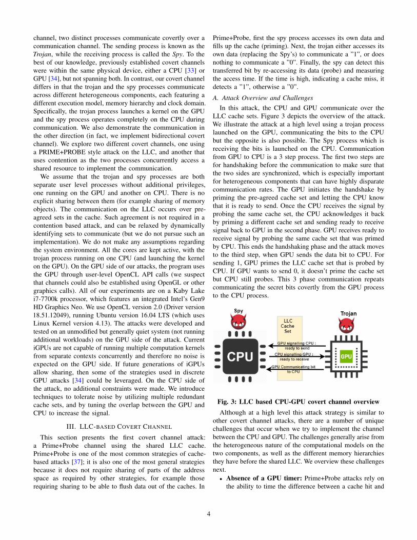
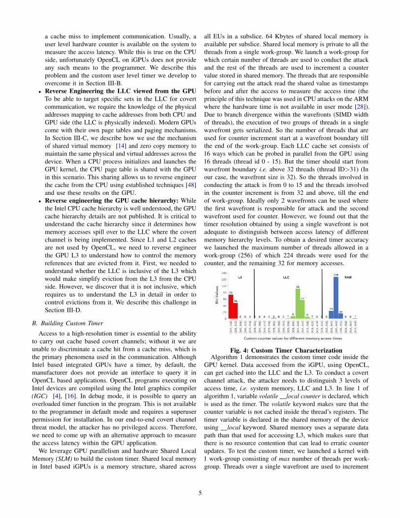
all EUs in a subslice. 64 Kbytes of shared local memory isavailable per subslice. Shared local memory is private to all thethreads from a single work-group. We launch a work-group forwhich certain number of threads are used to conduct the attackand the rest of the threads are used to increment a countervalue stored in shared memory. The threads that are responsiblefor carrying out the attack read the shared value as timestampsbefore and after the access to measure the access time (theprinciple of this technique was used in CPU attacks on the ARMwhere the hardware time is not available in user mode [28]).Due to branch divergence within the wavefronts (SIMD widthof threads), the execution of two groups of threads in a singlewavefront gets serialized. So the number of threads that areused for counter increment start at a wavefront boundary tillthe end of the work-group. Each LLC cache set consists of16 ways which can be probed in parallel from the GPU using16 threads (thread id 0 - 15). But the timer should start fromwavefront boundary i.e. above 32 threads (thread ID>31) (Inour case, the wavefront size is 32). So the threads involved inconducting the attack is from 0 to 15 and the threads involvedin the counter increment is from 32 and above, till the endof work-group. Ideally only 2 wavefronts can be used wherethe first wavefront is responsible for attack and the secondwavefront used for counter. However, we found out that thetimer resolution obtained by using a single wavefront is notadequate to distinguish between access latency of differentmemory hierarchy levels. To obtain a desired timer accuracywe launched the maximum number of threads allowed in awork-group (256) of which 224 threads were used for thecounter, and the remaining 32 for memory accesses.
Fig. 4: Custom Timer CharacterizationAlgorithm 1 demonstrates the custom timer code inside the
GPU kernel. Data accessed from the iGPU, using OpenCL,can get cached into the LLC and the L3. To conduct a covertchannel attack, the attacker needs to distinguish 3 levels ofaccess time, i.e. system memory, LLC and L3. In line 1 ofalgorithm 1, variable volatile local counter is declared, whichis used as the timer. The volatile keyword makes sure that thecounter variable is not cached inside the thread’s registers. Thetimer variable is declared in the shared memory of the deviceusing local keyword. Shared memory uses a separate datapath than that used for accessing L3, which makes sure thatthere is no resource contention that can lead to erratic counterupdates. To test the custom timer, we launched a kernel with1 work-group consisting of max number of threads per work-group. Threads over a single wavefront are used to increment
5
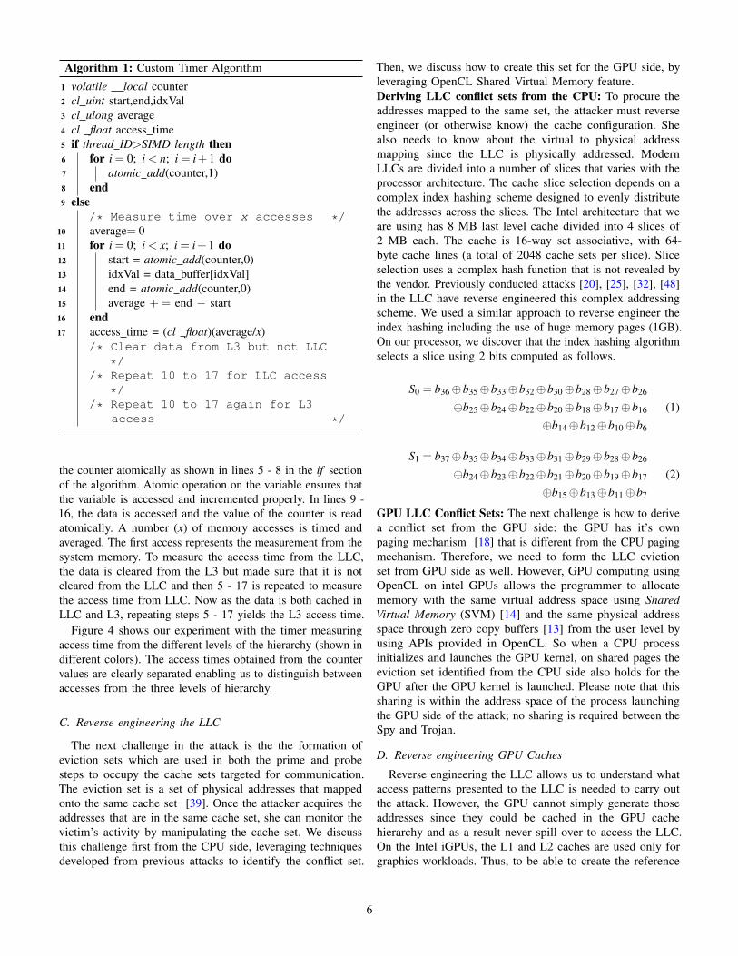
Algorithm 1: Custom Timer Algorithm
1 volatile local counter2 cl uint start,end,idxVal3 cl ulong average4 cl float access time5 if thread ID>SIMD length then6 for i = 0; i < n; i = i+1 do7 atomic add(counter,1)8 end9 else
/* Measure time over x accesses */10 average= 011 for i = 0; i < x; i = i+1 do12 start = atomic add(counter,0)13 idxVal = data buffer[idxVal]14 end = atomic add(counter,0)15 average += end − start16 end17 access time = (cl float)(average/x)
/* Clear data from L3 but not LLC
*//* Repeat 10 to 17 for LLC access
*//* Repeat 10 to 17 again for L3
access */
the counter atomically as shown in lines 5 - 8 in the if sectionof the algorithm. Atomic operation on the variable ensures thatthe variable is accessed and incremented properly. In lines 9 -16, the data is accessed and the value of the counter is readatomically. A number (x) of memory accesses is timed andaveraged. The first access represents the measurement from thesystem memory. To measure the access time from the LLC,the data is cleared from the L3 but made sure that it is notcleared from the LLC and then 5 - 17 is repeated to measurethe access time from LLC. Now as the data is both cached inLLC and L3, repeating steps 5 - 17 yields the L3 access time.
Figure 4 shows our experiment with the timer measuringaccess time from the different levels of the hierarchy (shown indifferent colors). The access times obtained from the countervalues are clearly separated enabling us to distinguish betweenaccesses from the three levels of hierarchy.
C. Reverse engineering the LLC
The next challenge in the attack is the the formation ofeviction sets which are used in both the prime and probesteps to occupy the cache sets targeted for communication.The eviction set is a set of physical addresses that mappedonto the same cache set [39]. Once the attacker acquires theaddresses that are in the same cache set, she can monitor thevictim’s activity by manipulating the cache set. We discussthis challenge first from the CPU side, leveraging techniquesdeveloped from previous attacks to identify the conflict set.
Then, we discuss how to create this set for the GPU side, byleveraging OpenCL Shared Virtual Memory feature.Deriving LLC conflict sets from the CPU: To procure theaddresses mapped to the same set, the attacker must reverseengineer (or otherwise know) the cache configuration. Shealso needs to know about the virtual to physical addressmapping since the LLC is physically addressed. ModernLLCs are divided into a number of slices that varies with theprocessor architecture. The cache slice selection depends on acomplex index hashing scheme designed to evenly distributethe addresses across the slices. The Intel architecture that weare using has 8 MB last level cache divided into 4 slices of2 MB each. The cache is 16-way set associative, with 64-byte cache lines (a total of 2048 cache sets per slice). Sliceselection uses a complex hash function that is not revealed bythe vendor. Previously conducted attacks [20], [25], [32], [48]in the LLC have reverse engineered this complex addressingscheme. We used a similar approach to reverse engineer theindex hashing including the use of huge memory pages (1GB).On our processor, we discover that the index hashing algorithmselects a slice using 2 bits computed as follows.
S0 = b36⊕b35⊕b33⊕b32⊕b30⊕b28⊕b27⊕b26
⊕b25⊕b24⊕b22⊕b20⊕b18⊕b17⊕b16
⊕b14⊕b12⊕b10⊕b6
(1)
S1 = b37⊕b35⊕b34⊕b33⊕b31⊕b29⊕b28⊕b26
⊕b24⊕b23⊕b22⊕b21⊕b20⊕b19⊕b17
⊕b15⊕b13⊕b11⊕b7
(2)
GPU LLC Conflict Sets: The next challenge is how to derivea conflict set from the GPU side: the GPU has it’s ownpaging mechanism [18] that is different from the CPU pagingmechanism. Therefore, we need to form the LLC evictionset from GPU side as well. However, GPU computing usingOpenCL on intel GPUs allows the programmer to allocatememory with the same virtual address space using SharedVirtual Memory (SVM) [14] and the same physical addressspace through zero copy buffers [13] from the user level byusing APIs provided in OpenCL. So when a CPU processinitializes and launches the GPU kernel, on shared pages theeviction set identified from the CPU side also holds for theGPU after the GPU kernel is launched. Please note that thissharing is within the address space of the process launchingthe GPU side of the attack; no sharing is required between theSpy and Trojan.
D. Reverse engineering GPU Caches
Reverse engineering the LLC allows us to understand whataccess patterns presented to the LLC is needed to carry outthe attack. However, the GPU cannot simply generate thoseaddresses since they could be cached in the GPU cachehierarchy and as a result never spill over to access the LLC.On the Intel iGPUs, the L1 and L2 caches are used only forgraphics workloads. Thus, to be able to create the reference
6
pattern from the GPU that will result in the eviction set addresspatterns to access the LLC, we must first reverse engineer theL3 cache on the GPU: if we understand the organization ofthe L3, we can design a memory reference pattern that causesthe desired LLC accesses to occur.
Most of previous attacks on last level caches depend on thecache inclusiveness property [48]. With inclusive caches, dataevicted from the lower level of caches also gets evicted fromthe higher level caches. As a first step of understanding the L3,we first determine whether it is indeed inclusive (we discoverthat it is not). Next, we reverse engineer the structure of thecache, and finally, we develop conflict sets that allow us tocontrol the traffic that gets presented to the LLC.L3 inclusiveness: To check whether the L3 is inclusive, wedesign the following experiment. We create a buffer sharedby the CPU and the GPU. We identify a set of n addresseswhich are accessed first by the GPU. Initially, the caches arecold, and the data is brought from memory and cached in bothLLC and L3. Next, the CPU accesses the same data bringingit into its caches and then flushes the data removing it from allthe cache levels using clflush. If the LLC is inclusive of theL3 cache, the removal of the flushed data from the LLC willcause back-invalidations to evict the data from the L3 cacheof the GPU as well. Finally, we check whether the data is stillpresent in the L3, by accessing the data from the GPU sideand timing it using our user timer. Based on access time, weobserved that the data is accessed from L3 and not from thememory, indicating that the L3 cache is not inclusive.L3 Architecture Details [19]: Figure 2 earlier in the papershows the L3 within the iGPU hierarchy. The total L3cache capacity may vary from one GPU generation to another.Irrespective of the total cache size, each slice of the iGPUis accompanied by its own L3 cache slice of size 768 KB.Each L3 cache slice is further divided into 4 cache banks, eachconsisting of 192 KB. This 192 KB is configured to 128 KBof L3 cache and 64 KB of Shared Local Memory (SLM).
The critical path to access the SLM is separate from theL3 access path. Accessing the SLM does not impact adverselyL3 access latency and vice versa, a feature that makes itpossible to implement our user level timer measurement withoutinterference from the memory traffic. The L3 uses a tree basedpLRU based cache replacement policy with (N−1) numberof nodes in the tree, N being the number of ways in the cacheset [19].L3 Eviction Set: Although [19] provides some architecturaldetails of the L3 structure, architectural information criticalto carry out a timing based PRIME+PROBE attack is stillmissing. Given that the L3 is non-inclusive, we cannot evictit from the CPU side, and instead need to create an evictionset from the GPU side to conduct a successful attack. In orderto form an eviction set in a particular cache level, an attackerrequires cache details like the cache line size, number of cachelines in a set and number of cache sets. Also understandingthe mapping of an address to a cache set is required to acquirethe addresses that are mapped to the same cache set. Afterfiguring out the addresses placed in the same cache set, an
attacker also considers the cache replacement policy to evictthe target address from the cache set. The total Cache Sizeis the product of the cache line size (CLS), number of cachelines per cache set (NL) and the number of cache sets (NS).
The understanding of L3 cache mapping is required to figureout the eviction set. We reverse engineer the configuration ofthe L3 and discover that the cache line size is 64B. GPUsare byte addressable and 6 bits in the address represent thebyte offset in the cache line. We identify that there are 64cache lines per cache set, with each cache set spanning 4 KBs.However, the L3 cache is partitioned into 4 banks and eachbank is again partitioned into 8 sub-banks. The number of setsper cache bank is 32 which requires 5 bits in the address bitsfor mapping. There are 4 cache banks which require additional2 bits in the address for mapping. Each cache bank is againdivided into 8 cache sub-banks which require additional 3 bitsin the address. So the total of 16 bits (6 bits byte offset + 5 bitsfor cache set + 2 bits for cache bank + 3 bits for sub-banks)in the address are required for the placement of the data in theL3 cache. We assumed a low order address interleaving whichdefines the 16 LSB bits. To verify the eviction set, we gatheredthe addresses with same 16 bits in the LSB and conductedthe eviction set test. As the replacement policy is pseudo-LRU(pLRU), accessing the other addresses multiple times (5 timesor more in our experiments) guarantees stable eviction of thetarget address through the pLRU.
During the attack phase on the LLC, we start with theaddresses that are in the same LLC set (selected from theLLC eviction set). In both, the priming and the probing phases,these addresses need to be evicted from the L3 so that theyare received by the LLC to implement the prime and probeat that level. To evict these target addresses from the L3, wecreate an eviction set from addresses that have the same last16 bits as the target address, which in turn ensures that thetarget and the eviction addresses are in the same L3 cache set.We are careful to choose eviction addresses for the L3 fromsets that are not our target at the LLC level. Otherwise, if theevict and target addresses lie in the same set at the LLC level,these evicted addresses add noise to the LLC set interferingwith the covert communication.
E. Putting it all together–LLC Channel
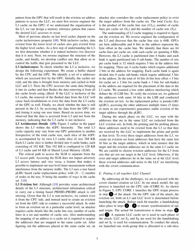
By addressing all the challenges, we are to proceed with thecovert channel creation on LLC. In our attack model, the spyprocess is launched on the CPU side (CORE 0). As shownin Figure 5, CPU CORE 1 launches the GPU trojan processin step 1 of the attack. On the GPU side of the attack, theeviction set, both on L3 and LLC level is determined beforelaunching the attack. Before each bit transfer, a handshakingtakes place in steps 2 - 5 to ensure synchronization of spyand trojan. The actual bit transmission is done in steps 6and 7 . A separate LLC cache set is used in each phase ofthe attack. LLC set SA and SB are used for the handshakingand set SC is used for communication. To conduct the attack,we launched one work-group that is allocated to a sub-slice.
7
The implementation requires synchronization between threadswhich can only be obtained within a work-group. In principle,this process can be replicated over multiple work-groups toscale bandwidth.
Fig. 5: LLC based CPU-GPU covert channel detailsThe GPU initiates the handshaking as data is transferred
from GPU to CPU. In the first phase of the handshaking, theGPU trojan process informs the CPU spy process that it isready to send the data. Step 2 indicates that GPU primesLLC set SA and then probing is done from the CPU side asshown in step 3 . To ensure the GPU accesses the data fromthe LLC and not the L3, those target addresses need to beevicted from the L3 due to the non-inclusive property of theL3, as shown in Section III-D. Eviction set creation on L3level is required to evict the target addresses from the L3. Weused a separate pollute buffer to evict the target addresses fromL3. The pollute buffer addresses and the target addresses arein the same L3 cache set, but lie in separate LLC sets to avoidpolluting the sets being used for the attack. After GPU primingis over, the CPU spy process probes the same set SA as shownin 3 . The higher level CPU L1 and L2 caches are inclusiveof the LLC. So after the GPU trojan process finishes priming,the data gets evicted from all levels of caches on the CPU spyprocess. As a result, the subsequent accesses reaches the LLCfrom the CPU.
The second phase of the handshaking indicates to the GPUtrojan process by the CPU spy process that it is ready to receive.In this phase, the CPU primes the LLC set SB in step 4 .Priming from the CPU on LLC requires creation of the evictionset on the LLC level. The GPU then probes the same cacheset SB in step 5 . Probing on the LLC from the GPU siderequires eviction on the L3 level again. So another eviction setis determined for a successful second handshaking phase. Inthis phase of handshaking, the access delay is measured fromthe GPU side. We use our custom timer to measure the delayas described in subsection III-B.
After the whole handshaking phase is over, the actual bittransmission occurs over LLC set SC as shown in steps 6 and
7 . The priming step 6 on the GPU side is similar to step2 in the first phase of the handshaking. The probing step 7
on the CPU side is similar to step 3 . Similar to previous steps, special consideration for L3 and LLC handling is required.The actual bit transmission takes place if the handshakingphase is successful. Step 1 is conducted once to launch thekernel on the GPU side. Steps 2 - 7 are conducted withinthe kernel in a for all loop for the number of bits that arerequired to be transferred.
We also built a reverse channel where the Trojan is on theCPU communicating to a Spy on the GPU. The technicaldetails and overflow of the attack are similar to the oppositedirection channel described above, but with the roles reversed.Specifically, the CPU initiates the handshake by priming setSA while the GPU receives it by probing the same set. Next,the GPU sends a ready to receive signal by priming set SB andthe CPU probes the same set to receive it. Finally, the CPUsends the communication bit to the GPU using set SC.Optimization around heterogeneous components: The CPUand GPU operate with different clock domains. The iGPU usesa clock rate of 1.1 GHz that is one-fourth of the CPU clock rate4.2 Ghz (not considering DVFS, which we did not observe onour desktop machine). This frequency imbalance leads to lossof coherence and inability to communicate. By the time GPUprimes an LLC set, CPU could already be finished probingleading to a missed communication. This affected both thebandwidth and reliability of our initial implementation. Toovercome this complication, we take the advantage of GPUthread level parallelism. We observed that as we increase thenumber of GPU threads, it reduces the frequency disparitybetween the prime and probe rates on the two sides. While theCPU primes/probes the LLC cache lines in a set serially, theslower GPU can match the cache access rate by operating inparallel.
IV. CONTENTION COVERT CHANNEL
Even with absent direct sharing of stateful microarchitecturalcomponents (such as the LLC), contention may arise whenthe two components share a bandwidth or capacity limitedmicroarchitectural structure such as buses or ports. In suchsituations, measurable contention can also be achieved if thetwo processes running on the two components access the samestructure concurrently (observing slow downs). Although thereare likely to be a number of such shared contention domainson our system, we implement an attack based on contentionon the ring bus connecting the CPU and GPU to the LLC.Specifically, when both the CPU and GPU generate traffic tothe LLC, they each observe delays higher than when only oneof them does, providing a way to communicate two states byeither creating contention or not.
Since contention relates to concurrent use of the sharedresource, it requires accurate synchronization between thetwo sides, which is challenging in the presence of the clockfrequency disparity between CPU and GPU. The CPU runsat 4x the speed of the GPU and the data access delay cannot
8
be observed if the GPU data access is lower than a limit.Through our systematic study, we identified the parametersthat contribute in creating a robust contention based channelwith low error rate and high bandwidth. We also devised aparameter that controls the frequency disparity between thecomputational resources. We describe the attack in more detailin the remainder of this section.Attack Overview: The attack creates contention on the ringbus between the CPU and GPU used to access the LLC. Duringthe attack, the CPU and GPU generate addresses chosen fromtheir own pre-allocated memory buffers. The CPU and GPUbuffers are chosen to map to different LLC sets to avoidLLC conflicts distorting the contention signal. With the twoprocesses accessing disjoint sets in the cache, the contentionoccurs strictly on the shared resources leading to the LLC.
The attack overview is present in Figure 6. The CPU processis launched in CORE 0 and a GPU process is launched inCORE 1 as shown in step 1 and 2 . The processes launcheach carries out data allocation and initialization. The trojanprocess launched on CORE 1 launches the GPU kernel asshown in step 3 . The data is accessed by the CPU and GPUsimultaneously. The first access will warm-up the cache andbring the CPU and GPU data to the LLC, steps 4 and 5 .Subsequent memory accesses would hit the LLC and generatecontention among the shared resources as shown in step 6 .This contention among the shared resources gets reflectedduring the data access by the CPU.
Fig. 6: Contention channel attack methodologyContention Channel Implementation: To build the covertchannel, we need to identify different parameters that contributetowards building the channel to be able to systematically createand optimize the attack. For the CPU, TCPU is the time requiredto access SCPU bytes of data. With the simultaneous access fromthe GPU, the access time is increased by TOV . The total timeTTOTALCPU required to access the data from the CPU during thesimultaneous GPU access is given in Equation 3. The overheadcreated due to simultaneous access is a function of the SGPUbytes of data accessed by GPU, number of threads launched
NUMT hreads and an Iteration Factor factor IF reflecting howmany iterations the data is accessed as shown in Equation 4.One constraint is to keep both, CPU and GPU data, in the lastlevel cache; the the total of SGPU and SCPU has to be less thanthe total size of the last level cache, as shown in Equation 5.Another constraint is that the LLC sets that are mapped to theCPU buffer should not coincide with the sets that are mappedto the GPU buffer, as shown in equation 6.
TTOTALCPU = TCPU +TOV (3)TOV = f (IF). f (SGPU ). f (NUMT hreads) (4)
s.t. SCPU +SGPU � SLLC (5)SCPU ∩SGPU = /0 (6)
On the CPU side of the attack, a buffer size of SCPU byteshas been created. The accesses are done at an offset of cacheline size of 64b. So the number of accesses are equivalent tothe number of cache lines in the allocated buffer. The datais accessed in a random pointer chasing manner to lowerprefetching effects that may cause replacements of either theCPU or GPU data in the LLC. First, LLC is warmed up. Thesubsequent accesses would be serviced from the LLC. Thesize of the buffer is chosen to ensure that the data is evictedfrom local caches but not from the LLC. Each access time ismeasured by clock gettime().
On the GPU side, the number of cache lines needed to beaccessed is divided among the number of threads launched.The number of memory addresses that each thread needs toaccess, numElsPerThread, is shown in in Equation 7.
numElsPerThread =number of cache lines
number of threads(7)
One of the novel problems presented by asymmetric covertchannels is that the two sides have an asymmetric view of theresource; for example, the GPU and CPU operate at differentfrequencies, and the GPU must overflow the L3 cache togenerate an access to the LLC, which unlike the CPU siderequires deriving different conflict sets due to the differentindexing scheme. Without calibration, this mismatch can lead toinefficient communication, reducing bandwidth and increasingerrors. We introduce the notion Iteration Factor IF to allow usto align the two ends of the channel as shown in equation 4.For a given GPU buffer size, the execution time varies basedon the number of work-groups launched. IF (the number ofiterations the data is accessed on the GPU) ensures that theratio between the GPU and CPU execution time is near 1.
V. EVALUATION
In this section, we evaluate the two covert channels in termsof channel bandwidth and error rate.LLC-based Covert Channel: The GPU L3 cache is non-inclusive which requires it to be filled to overflow and accessthe LLC. Figure 7 shows the bandwidth of the channel on bothdirections (CPU-to-GPU and GPU-to-CPU channels) basedon different strategies to overflow the L3. The naive way toestablish the covert channel can be performed by clearing the
9
whole L3 cache (we can use the GPU parallelism to acceleratethis process); the advantage here is that we do not have toreverse engineer the L3 organization. However, clearing upthe whole L3 data cache of 512 KB, even with thread levelparallelism, substantially reduces bandwidth. Figure 7 showsthe bandwidth of the LLC based covert channel is 1 kb/s, whenthe whole L3 is cleared in every iteration. The next level ofoptimization implemented to increase the channel bandwidthis to identify minimum number of addresses that is requiredto evict all the target addresses in the same LLC set withthe constraint that these addresses reside in separate LLC setsfrom the target set. Otherwise, it would create noise due to selfeviction. This approach requires only knowledge of the LLCand not L3. This bandwidth we achieved using this technique,is 70 kb/s for GPU-to-CPU channel (67 kb/s for CPU-to-GPUchannel). Further optimization was achieved by carrying outthe complete L3 reverse engineering and creating its evictionsets, determining the addresses that are in the same L3 setfor precise eviction of the target addresses. This next fold ofoptimization increases the bandwidth to 120 kb/s (118 kb/sfor CPU-to-GPU channel), which is a respectable bandwidthgiven that each GPU memory reference to the LLC must firstbe evicted from the L3. The error percentage of the precise L3eviction came out to be as low as 2% (6% for CPU-to-GPUchannel). We achieved a stable channel with a low error rateand high bandwidth through our optimization of precise L3set eviction. However, the error rate is higher in the case ofCPU-to-GPU channel. The primary reason is the increasedusage of the custom timer during the first stage of handshakeas well as during the bit communication that misinterprets themisses as hits.
Fig. 7: LLC bandwidth (different L3 eviction strategies)To reduce the error rate and increase channel resilience we
used multiple LLC sets. Monitoring cache misses over multiplesets provides us with better resolution than using a single setfor communication. However, the redundancy causes reductionin available bandwidth; potentially we could have used thesemultiple sets to communicate multiple bits in parallel. Figure8 shows the bandwidth and error rate with respect to theincreasing of number of LLC sets. When we are using only1 set then the error rate is 7% for GPU-to-CPU channel (9%for the CPU-to-GPU channel), which reduces to 2% as thenumber of sets doubled. For CPU-to-GPU channel that errorrate reduces to 6%. However, the bandwidth reduces by 6.25%from 128 Kb/s to 120 Kb/s which is acceptable reduction
given the error rate reduces by more than 71%. The bandwidthreduces to 118 Kb/s from 125 Kb/s by doubling the cacheset in the cases of CPU-to-GPU based channel. Increasing thenumber of sets does not provide any improvement on the errorrate. However, the bandwidth reduces at a steady rate. In ourattacks, we used 2 sets for all the 3 stages of attack resultingin using 6 LLC cache sets.
Fig. 8: Error and BW with number of LLC setsContention-based Covert Channel: CPU and GPU accessthe LLC using asymetric pathways and computational models.This impacts the success rate of the communication betweenthe two asymmetric sides. We introduce the concept of IterationFactors to match the rate of communication between the twosides (as discussed in Section IV). Figure 9 shows the optimaliteration factor: keeping the CPU buffer size constant, as theGPU buffer size increases, the factor reduces correspondinglyto enable overlap between the two sides.
Fig. 9: Iteration Factor for different buffer sizesAs discussed in Section IV, in our contention based covert
channel, buffer size on both CPU and GPU side and thenumber of work-groups that access to the GPU buffer, affect thecontention pattern and consequently the channel bandwidth anderror rate. We perform a search on the parameter space to obtaina channel with low acceptable error rate and high bandwidth.Figure 10 shows the evaluation results of the contention basedcovert channel. The different graphs are for different GPUbuffer size and a constant CPU buffer size of 512 KB. TheGPU buffer size that we considered are 1 MB, and 2 MB.Each result shows a confidence interval of 95% over 1000runs of the experiment. The bandwidth and the error rate areshown for different number of work-groups (in the X-axis).We obtained an error rate which is lower than 2% for more
10
Fig. 10: Bandwidth and error for bus-based channel
than 90% of the configuration space. The lowest error rate thatwe obtained is 0.82% for CPU buffer size of 512 KB, GPUbuffer size of 2 MB and number of work-groups of 2. We canobserve that the bandwidth follows the pattern of the error rate(lower bandwidth for low error rate). The bandwidth rangesfrom 390 kb/s to 402 kb/s. The bandwidth corresponding tothe lowest error rate is 392.4 kb/s.
VI. POSSIBLE MITIGATIONS
We believe classes of defenses that have been developedagainst other microarchitectural covert channels can alsopotentially apply to cross component attacks on heterogeneoussystems. These solutions include: (1) Static or dynamicpartitioning of resources [6], [21], [27], [29], [42], specificallythe LLC. These partitioning schemes can be extended tosupport different processors in heterogeneous systems. If theSpy and Trojan use different partitions of the cache, they arenot able to replace each other’s cache lines; and (2) Eliminatingthe contention among processes by traffic control in memorycontrollers [38], [40], such that memory requests from eachprocessor are grouped into the same queue and possibly accessthe same memory bank/port. Prior work [24] demonstratedthat an efficient memory scheduling strategy and isolatingthe CPU memory requests from the GPU memory requestswill improve the system performance, since memory requestsfrom the GPU seriously interfere with the CPU memoryaccess performance. Such isolation can be applied to the ringbus connecting the CPU and GPU to the LLC (with LLCpartitioning in place). Other solutions such as adding noiseto the timer may also apply [31]. However, we build ourcustomized timer using hardware resource (shared memory)available on GPU, so disabling the timing infrastructure in ourattack is not straightforward.
VII. RELATED WORK
Microarchitectural covert-channel and side-channel attackshave been widely studied on different resources on CPUsincluding the L1 cache [3], [7], [37] and shared LLC in multi-core CPUs [12], [25], [28], [30], [47], [49]. Some works exploit
cache coherency protocols to develop timing channels on multi-core CPUs [45], [46] or multi-CPU systems [11].
Some recent work demonstrates that GPUs are also vulnera-ble to microarchitectural covert and side-channel attacks. Thesework has been proposed on discrete GPUs with a dedicatedmemory. Jiang et al. [22], [23] present architectural timingattacks from the CPU to the GPU. The attack triggers anAES computation on the GPU, and times it showing that thereexists correlation the measured time (which varies due to keydependent memory coalescing behavior) and the last round keyin AES encryption. Naghibijouybari et al. [34] construct severaltypes of covert channels on different resources within a GPU.Naghibijouybari et al. also demonstrate a series of end-to-endGPU side channel attacks covering the different threat scenarioson both graphics and computational stacks, as well as acrossthem [35]. They implements website fingerprinting throughGPU memory utilization API or GPU performance counters,track user activities as they interact with a website or typecharacters on a keyboard. In addition, they develop a neuralnetwork model extraction attack, demonstrating that theseattacks are also dangerous on the cloud. On the defense side,Xu et al. [44] proposed a GPU-specific intra-SM partitioningscheme to isolate contention between victim and spy andeliminate contention based channels after detection.
All of these microarchitectural attacks and defenses havebeen proposed on a single processor (CPU or discrete GPU).Inthis paper, for the first time, we develop microarchitecturalcovert channels in more widely used integrated CPU-GPUsystems. The integrated GPU is available through APIs suchas WebGL [2] even for remote Javascript programs makingthis threat vector extremely dangerous. There have been alimited number of attacks on heterogeneous systems (but nottiming attacks): Weissman et al. [43] study rowhammer attackson heterogeneous FPGA-CPU platforms. Frigo et al. [10] useWebGL timing APIs to implement GPU accelerated rowhammerattack on memory in integrated CPU-GPU systems in mobileSOCs. They use WebGL timer to find contiguous area ofphysical memory to conduct the rowhammer. We investigatea different threat model, microarchitectural covert channels,showing for the first time that these attacks can apply acrosscomponents in a heterogeneous system.
VIII. CONCLUDING REMARKS
To the best of our knowledge, we present the first mi-croarchitectural covert channel attacks that span two differentcomponents in an SoC with an asymmetric view of the resource.Specifically, each component has a different view of the sharedresource that they use to create contention. Beyond the extracomplexity of reverse engineering two different pathways to theshared resource, this also introduces additional novel difficultiesthat arise due to this asymmetry. For example, the LLC isinclusive on the CPU side, but non-inclusive on the GPUside. Moreover, the indexing of the GPU cache hierarchy isdifferent from that of the LLC; as we create conflict sets tooverflow the L3 on the GPU, we run the risk of creating self-interference with other sets on the LLC. We also needed to
11
calibrate the communication loops to improve the bandwidthgiven the asymmetric pathways to access the channel.
Although we demonstrated one instance of cross-componentattacks (specifically, an integrated GPU and CPU) in heteroge-neous systems, the threat model can be extended to includeany other accelerator or components, sharing resources withCPUs. Having experience with these channels improves ourunderstanding of the threats posed of microarchitectural attacksbeyond a single component which is a threat model increasingin importance as we move increasingly towards heterogeneouscomputing platforms. We created two working channels: aPrime+Probe channel targeting the LLC, and a contention basedchannel exploiting contention on the shared access pathwayto the LLC. Creating the channels required overcoming a setof challenges that we believe will be representative of thoseneeded for cross-component attacks. Both channels achievehigh bandwidth and low error rate.
IX. ACKNOWLEDGEMENT
Pacific Northwest National Laboratory is operated by BattelleMemorial Institute for the U.S. Department of Energy underContract No. DE-AC05-76RL01830. This work was supportedby the U.S. Department of Energy, Office of AdvancedScientific Computing Research (ASCR) through the Center forAdvanced Technology Evaluation (CENATE) project, Contract#66150B. This work is also partially supported by NationalScience Foundation grant CNS-1619450.
REFERENCES
[1] “OpenCL Overview, Khronos Group,” 2018, https://www.khronos.org/opencl/.
[2] “WebGL Overview, Khronos Group,” 2018, https://www.khronos.org/webgl/.
[3] B. B. Brumley and R. M. Hakala, “Cache-timing template attacks,” inAdvances in Cryptology – ASIACRYPT 2009, M. Matsui, Ed. Berlin,Heidelberg: Springer Berlin Heidelberg, 2009, pp. 667–684.
[4] A. Chandrasekhar, G. Chen, P.-Y. Chen, W.-Y. Chen, J. Gu, P. Guo, S. H. P.Kumar, G.-Y. Lueh, P. Mistry, W. Pan, T. Raoux, and K. Trifunovic,“Igc: The open source intel graphics compiler,” in Proceedings of the2019 IEEE/ACM International Symposium on Code Generation andOptimization, ser. CGO 2019. IEEE Press, 2019, p. 254–265.
[5] J. Chen and G. Venkataramani, “Cc-hunter: Uncovering covert timingchannels on shared processor hardware,” in Proceedings of the Interna-tional Symposium on Microarchitecture (MICRO), 2014.
[6] L. Domnitser, A. Jaleel, J. Loew, N. Abu-Ghazaleh, and D. Ponomarev,“Non-monopolizable caches: Low-complexity mitigation of cache sidechannel attacks,” ACM Transactions on Architecture and Code Optimiza-tion (TACO), vol. 8, no. 4, pp. 1–21, 2012.
[7] D. A. O. Eran Tromer and A. Shamir, “Efficient cache attacks on aes,and countermeasures,” in Journal of Cryptology, 2009, pp. 667–684.
[8] D. Evtyushkin and D. Ponomarev, “Covert channels through randomnumber generator: Mechanisms, capacity estimation and mitigations,” inCCS, 2016.
[9] D. Evtyushkin, D. Ponomarev, and N. Abu-Ghazaleh, “Understanding andmitigating covert channels through branch predictors,” ACM Transactionson Architecture and Code Optimization, vol. 13, no. 1, p. 10, 2016.
[10] P. Frigo, C. Giuffrida, H. Bos, and K. Razavi, “Grand pwning unit:Accelerating microarchitectural attacks with the gpu,” in Proceedings ofIEEE Symposium on Security and Privacy, 2018, pp. 357–372.
[11] T. R. E. Gorka Irazoqui and B. S. profile, “Cross processor cacheattacks,” in Proceedings of the 11th ACM on Asia Conference onComputer and Communications Security, 2016, pp. 353–364. [Online].Available: https://doi.org/10.1145/2897845.2897867
[12] D. Gruss, R. Spreitzer, and S. Mangard, “Cache templateattacks: Automating attacks on inclusive last-level caches,” in24th USENIX Security Symposium (USENIX Security 15). Washington,D.C.: USENIX Association, Aug. 2015, pp. 897–912. [Online].Available: https://www.usenix.org/conference/usenixsecurity15/technical-sessions/presentation/gruss
[13] Intel. (2014) Getting the most from opencl™ 1.2: How to increaseperformance by minimizing buffer copies on intel® processor graphics.[Online]. Available: https://software.intel.com/sites/default/files/managed/f1/25/opencl-zero-copy-in-opencl-1-2.pdf
[14] Intel. (2014) Opencl 2.0 shared virtual memory overview.[Online]. Available: https://software.intel.com/en-us/articles/opencl-20-shared-virtual-memory-overview
[15] Intel. (2015) Intel processor graphics gen9 architecture. [Online]. Avail-able: https://software.intel.com/sites/default/files/managed/c5/9a/The-Compute-Architecture-of-Intel-Processor-Graphics-Gen9-v1d0.pdf
[16] Intel. (2019) Intel graphics compiler. [Online]. Available: https://github.com/intel/intel-graphics-compile
[17] Intel. (2019) Intel processor graphics gen11 architecture. [Online].Available: https://software.intel.com/sites/default/files/managed/db/88/The-Architecture-of-Intel-Processor-Graphics-Gen11 R1new.pdf
[18] Intel. (2019) Intel® open source hd graphics and intel iris™ plusgraphics programmer’s reference manual: Volume 5: Memory views.[Online]. Available: https://01.org/sites/default/files/documentation/intel-gfx-prm-osrc-kbl-vol05-memory views.pdf
[19] Intel. (2019) Intel® open source hd graphics and intel iris™ plusgraphics programmer’s reference manual: Volume 7: 3d-media-gpgpu.[Online]. Available: https://01.org/sites/default/files/documentation/intel-gfx-prm-osrc-kbl-vol07-3d media gpgpu.pdf
[20] G. Irazoqui, T. Eisenbarth, and B. Sunar, “Systematic reverse engineer-ing of cache slice selection in intel processors,” in 2015 EuromicroConference on Digital System Design. IEEE, 2015, pp. 629–636.
[21] R. Iyer, L. Zhao, F. Guo, R. Illikkal, S. Makineni, D. Newell,Y. Solihin, L. Hsu, and S. Reinhardt, “Qos policies and architecturefor cache/memory in cmp platforms,” in Proceedings of the 2007ACM SIGMETRICS International Conference on Measurement andModeling of Computer Systems, ser. SIGMETRICS ’07. New York, NY,USA: Association for Computing Machinery, 2007, p. 25–36. [Online].Available: https://doi.org/10.1145/1254882.1254886
[22] Z. H. Jiang, Y. Fei, and D. Kaeli, “A complete key recoverytiming attack on a gpu,” in IEEE International Symposium onHigh Performance Computer Architecture, ser. HPCA’16. BarcelonaSpain: IEEE, March 2016, pp. 394–405. [Online]. Available:http://ieeexplore.ieee.org/document/7446081
[23] Z. H. Jiang, Y. Fei, and D. Kaeli, “A novel side-channel timing attackon gpus,” in Proceedings of the on Great Lakes Symposium on VLSI, ser.VLSI’17, 2017, pp. 167–172.
[24] M. W. Juan Fang and Z. Wei, “A memory scheduling strategy foreliminating memory access interference in heterogeneous system,” inThe Journal of Supercomputing, vol. 76, 2020, p. 3129–3154.
[25] M. Kayaalp, D. Ponomarev, N. Abu-Ghazaleh, and A. Jaleel, “A high-resolution side-channel attack on last-level cache,” in Proceedings of the53th Annual Design Automation Conference, June 2016.
[26] S. K. Khatamifard, L. Wang, S. Kose, and U. R. Karpuzcu, “A new classof covert channels exploiting power management vulnerabilities,” IEEEComputer Architecture Letters, vol. 17, no. 2, pp. 201–204, 2018.
[27] J. Kong, O. Aciicmez, J.-P. Seifert, and H. Zhou, “Hardware-softwareintegrated approaches to defend against software cache-based sidechannel attacks,” in Proceedings of the International Symposium onHigh Performance Comp. Architecture (HPCA), February 2009.
[28] M. Lipp, D. Gruss, R. Spreitzer, C. Maurice, and S. Mangard,“Armageddon: Cache attacks on mobile devices,” in 25th USENIX SecuritySymposium (USENIX Security 16). Austin, TX: USENIX Association,Aug. 2016, pp. 549–564. [Online]. Available: https://www.usenix.org/conference/usenixsecurity16/technical-sessions/presentation/lipp
[29] F. Liu, Q. Ge, Y. Yarom, F. Mckeen, C. Rozas, G. Heiser, and R. Lee,“Catalyst: Defeating last-level cache side channel attacks in cloudcomputing,” in Proceedings of the International Symposium on HighPerformance Computer Architecture (HPCA), 2016.
[30] F. Liu, Y. Yarom, Q. Ge, G. Heiser, and R. B. Lee, “Last-level cacheside-channel attacks are practical,” in Security and Privacy (SP), May2015.
[31] R. Martin, J. Demme, and S. Sethumadhavan, “Timewarp: Rethinkingtimekeeping and performance monitoring mechanisms to mitigate side-
12
channel attacks,” in Proc. International Symposium on ComputerArchitecture (ISCA), 2012, pp. 118–129.
[32] C. Maurice, N. Le Scouarnec, C. Neumann, O. Heen, and A. Francillon,“Reverse engineering intel last-level cache complex addressing usingperformance counters,” in International Symposium on Recent Advancesin Intrusion Detection. Springer, 2015, pp. 48–65.
[33] C. Maurice, C. Neumann, O. Heen, and A. Francillon, “C5: cross-corescache covert channel,” in International Conference on Detection ofIntrusions and Malware, and Vulnerability Assessment. Springer, 2015,pp. 46–64.
[34] H. Naghibijouybari, K. Khasawneh, and N. Abu-Ghazaleh, “Constructingand characterizing covert channels on gpus,” in Proc. InternationalSymposium on Microarchitecture (MICRO), 2017, pp. 354–366.
[35] H. Naghibijouybari, A. Neupane, Z. Qian, and N. Abu-Ghazaleh,“Rendered insecure: Gpu side channel attacks are practical,” inProceedings of the 2018 ACM SIGSAC Conference on Computerand Communications Security, ser. CCS ’18. New York, NY,USA: ACM, 2018, pp. 2139–2153. [Online]. Available: http://doi.acm.org/10.1145/3243734.3243831
[36] Nvidia. (2019) Cuda c++ programming guide. [Online]. Available:https://docs.nvidia.com/pdf/CUDA C Programming Guide.pdf
[37] C. Percival, “Cache missing for fun and profit,” in BSDCan, 2005.[38] A. Shafiee, A. Gundu, M. Shevgoor, R. Balasubramonian, and M. Tiwari,
“Avoiding information leakage in the memory controller with fixedservice policies,” in Proceedings of the International Symposium onMicroarchitecture (MICRO), Dec. 2015.
[39] P. Vila, B. Kopf, and J. F. Morales, “Theory and practice of findingeviction sets,” in 2019 IEEE Symposium on Security and Privacy (SP).IEEE, 2019, pp. 39–54.
[40] Y. Wang and G. E. Suh, “Timing channel protection for a shared memorycontroller,” in Proceedings of the International Symposium on HighPerformance Computer Architecture (HPCA), Feb. 2014.
[41] Z. Wang and R. B. Lee, “Covert and side channels due to processorarchitecture.” in Computer Security Applications Conference (ACSAC),2006.
[42] Z. Wang and R. B. Lee, “New cache designs for thwarting softwarecache-based side channel attacks,” in Proceedings of the InternationalSymposium on Computer Architecture (ISCA), 2007.
[43] Z. Weissman, T. Tiemann, D. Moghimi, E. Custodio, T. Eisenbarth, andB. Sunar, “Jackhammer: Efficient rowhammer on heterogeneous fpga-cpuplatforms,” in arXiv:1912.11523, 2020.
[44] Q. Xu, H. Naghibijouybari, S. Wang, N. Abu-Ghazaleh, andM. Annavaram, “Gpuguard: Mitigating contention based side andcovert channel attacks on gpus,” in Proceedings of the ACMInternational Conference on Supercomputing, ser. ICS ’19. NewYork, NY, USA: ACM, 2019, pp. 497–509. [Online]. Available:http://doi.acm.org/10.1145/3330345.3330389
[45] M. Yan, R. Sprabery, B. Gopireddy, C. Fletcher, R. Campbell, andJ. Torrellas, “Attack directories, not caches: Side channel attacks in anon-inclusive world,” in 2019 2019 IEEE Symposium on Security andPrivacy (SP). Los Alamitos, CA, USA: IEEE Computer Society, may2019. [Online]. Available: https://doi.ieeecomputersociety.org/10.1109/SP.2019.00004
[46] F. Yao, M. Doroslovacki, and G. Venkataramani, “Are coherenceprotocol states vulnerable to information leakage?” in Proceedings of theInternational Symposium on High Performance Computer Architecture(HPCA), Feb. 2018.
[47] Y. Yarom and K. Falkner, “Flush+reload: A high resolution, low noise,l3 cache side-channel attack,” in 23rd USENIX Security Symposium(USENIX Security 14). San Diego, CA: USENIX Association,Aug. 2014, pp. 719–732. [Online]. Available: https://www.usenix.org/conference/usenixsecurity14/technical-sessions/presentation/yarom
[48] Y. Yarom, Q. Ge, F. Liu, R. B. Lee, and G. Heiser, “Mapping the intellast-level cache.” IACR Cryptology ePrint Archive, vol. 2015, p. 905,2015.
[49] M. K. R. Yinqian Zhang, Ari Juels and T. Ristenpart, “Cross-tenant side-channel attacks in paas clouds,” in Proceedings of the 2014 ACM SIGSACConference on Computer and Communications Security, 2014, pp.990–1003. [Online]. Available: https://doi.org/10.1145/2660267.2660356
13