learning-based adaptive transmission for limited feedback...
TRANSCRIPT

1
Learning-Based Adaptive Transmission forLimited Feedback Multiuser MIMO-OFDM
Alberto Rico-Alvarino, Student Member, IEEE and Robert W. Heath Jr. Fellow, IEEE
Abstract—Performing link adaptation in a multiantenna andmultiuser system is challenging because of the coupling betweenprecoding, user selection, spatial mode selection and use of limitedfeedback about the channel. The problem is exacerbated by thedifficulty of selecting the proper modulation and coding schemewhen using orthogonal frequency division multiplexing (OFDM).This paper presents a data-driven approach to link adaptationfor multiuser multiple input mulitple output (MIMO) OFDMsystems. A machine learning classifier is used to select the mod-ulation and coding scheme, taking as input the SNR values in thedifferent subcarriers and spatial streams. A new approximationis developed to estimate the unknown interuser interference dueto the use of limited feedback. This approximation allows toobtain SNR information at the transmitter with a minimumcommunication overhead. A greedy algorithm is used to performspatial mode and user selection with affordable complexity, with-out resorting to an exhaustive search. The proposed adaptationis studied in the context of the IEEE 802.11ac standard, and isshown to schedule users and adjust the transmission parametersto the channel conditions as well as to the rate of the feedbackchannel.
Index Terms—Link adaptation, multiuser MIMO-OFDM,IEEE 802.11ac, machine learning
I. INTRODUCTION
Dynamically adapting the transmitter in response to chang-ing channel conditions is key to achieving both throughput andreliability on wireless communication links. Reconfiguratingthe link requires adjusting several transmission parameters: themodulation and coding scheme (MCS), the multiple input mul-tiple output (MIMO) precoding matrices in multiple antennasystems, the spatial mode (number of spatial data streamsfor each user), and the assignment of transmit resources forthe different users, among other parameters. These valuesare selected based on the available channel state information(CSI) at the transmitter (CSIT). Most modern communicationsystems, including cellular technologies (3GPP LTE [2], IEEE802.16 [3]), wireless local area networks (IEEE 802.11 [4])and satellite standards (DVB-S2 [5], DVB-RCS [6]) includesome kind of link adaptation mechanism.
Manuscript received June 3, 2013; revised August 21, 2013 and December31, 2013; accepted March 14, 2014. The associate editor coordinating thereview of this paper and approving it for publication was Mai Vu.
A. Rico-Alvarino is with the Signal Theory and Communications Depart-ment, University of Vigo, Galicia, Spain. (e-mail: [email protected]).
R. W. Heath Jr. is with the Department of Electrical and ComputerEngineering, The University of Texas at Austin, TX, USA. (e-mail:[email protected]).
This work was performed while the first author was visiting the WirelessNetworking and Communications Group at The University of Texas at Austin.Work by A. Rico-Alvarino supported by a Fundacion Pedro Barrie de la Mazagraduate scholarship. Work by R. W. Heath Jr. supported by the NationalScience Foundation Grant 1218338 and by the Army Research Laboratorycontract W911NF-10-1-0420.
A preliminary version of this work was presented in EUSIPCO 2013 [1].
Classic work on link adaptation focused on narrowbandfading. For example, the modulation and power were dynam-ically adjusted with constraints on the uncoded bit error rate(BER) and average transmit power to maximize the spectralefficiency [7], [8]. The extension of these approaches to codedtransmission resulted in more complicated analytical expres-sions, and usually required the use of BER approximations [9],[10]. The MCS selection problem in [7]–[10] is essentially aunidimensional problem that consists of assigning a signal tonoise ratio (SNR) interval to each MCS. A different approachto link adaptation can be seen in works like [11], [12], wherethe transmit rate is modified without taking into account thecurrent channel state, but only with ACK/NAK information.
Link adaptation in systems with multiple channels is morechallenging due to the higher dimensionality of the CSI. Thechannel state cannot be characterized with a single SNR valuein systems using orthogonal frequency division multiplexing(OFDM) or MIMO with spatial multiplexing. The reason isthat different symbols in the same codeword experience differ-ent SNR values. Because of the complicated mapping betweencodeword error and symbol error, the average SNR may notcontain enough information to permit effective adaptation [13].An alternative is to map the set of SNR values (one for eachcarrier and spatial stream) to one effective SNR [14]–[18].The effective SNR is defined as the SNR for an additive whiteGaussian noise (AWGN) channel to experience the same frameerror rate (FER) as the fading channel under study. EffectiveSNR metrics are defined as a Kolmogorov mean [19] of theSNR values with some parameters that are fitted accordingto empirical results. The WiMAX forum, for example, rec-ommends the exponential effective SNR metric as the defaultmethod for FER prediction [20] in IEEE 802.16e. The effectiveSNR metrics lead to adaptation algorithms in the form of look-up tables, where each effective SNR value is associated to anMCS. Some works like [21] make use of effective SNR metricsto develop link adaptation algorithms in single user scenarios.Having a fixed mapping between effective SNR and MCS isnot ideal due to the impact of practical impairments like non-linearities, non-Gaussian noise or implementation-dependentparameters, like Viterbi truncation depth or number of roundsin a turbo decoder.
Data-driven approaches provide a solution to the problemof mapping an appropriate FER to the set of SNR values.Based on empirical observations of the SNR values and theirassociated FER, learning algorithms have been designed toselect the proper MCS for each channel realization [22]–[27].This classification task is performed by machine learning al-gorithms like K-nearest neighbors or support vector machines(SVM) [28]. These algorithms are usually described as non-

2
parametric, since they do not assume any model that mapsSNR values to FER, but try to learn it from empirical data.Learning can be performed online [25]–[27] or offline [22],[24], and is usually based on a low dimensional feature setcontaining a subset of the ordered SNR values [29]. Thisdata-driven formulation was shown to outperform the effectiveSNR in [22], and is resiliant to practical impairments like non-Gaussian noise or amplifier non-linearities [26].
Prior work in learning-based link adaptation focused insingle user scenarios [22]–[26]. The extension of these ap-proaches to the more general case of having multiple usersserved at the same time by the use of space division multiplex-ing (SDM) is not trivial due to the interaction between userselection, mode selection, and MCS selection. For example,the link adaptation algorithm in [22] requires running theclassification algorithm for all possible number of spatialstreams (NSS) and selecting the NSS leading to a higherthroughput. Applying a similar strategy in the multiuser casewould require an additional exhaustive search over the choiceof users and the number of spatial streams per user.
Prior work in learning-based link adaptation also did notconsider the impact of limited feedback precoding [22]–[26].In multiuser MIMO (MU-MIMO) systems, limited feedbackcreates quantization error that results in residual interuserinterference [30]. The resulting interference makes perfor-mance a function of the feedback quality. Therefore a smartmultiuser link adaptation algorithm should predict the interuserinterference and move from aggressive multiuser transmissionto more conservative modes depending on the feedback quality[31].
In this paper, we present a data-driven link adaptationmethod that includes user selection, mode selection, precoding,MCS selection, and limited feedback. The main objective ofthe paper is to give insight into the effect of limited feedbackin MU-MIMO systems with link adaptation. To do so, oursolution assumes perfect CSI at the receivers, and differentdegrees of CSI at the transmitter. With this information, andtaking into account the degradation due to CSI inaccuracy,the transmitter is able to perform link adaptation. Our workis different from previous approaches in several ways. Thefocus of [32], [33] is to study fairness in a multiuser setting,with limited feedback information not taken into account, andMCS selection is performed by means of effective SNR. In[34], only a single spatial stream is allowed per user, and theeffective SNR approach is followed for MCS selection. In [35],adaptation is performed following a data-driven approach, andlimited feedback is taken into account, but the communicationscenario is multicast (i.e., there is only a common messagefor all receivers). Our paper studies the broadcast scenario,takes into account limited feedback, includes the possibilityof transmitting more than one spatial stream to each user, andperforms MCS selection following a data driven approach.
We focus on the multiuser capabilities of IEEE 802.11ac[36] to develop our link adaptation method. We consider thisstandard due to its novelty and the challenging constraint ofnot allowing user allocation among subcarriers, like in LTEor WIMAX. The adaptation is performed at the access point(AP), thus requiring a minimum communication overhead
with the user stations (STA) to obtain CSI. This AP-centricapproach is specially suitable for link adaptation in scenarioswith cheap STAs, as they might not implement some of theoptional features in IEEE 802.11ac to perform MCS selection.
The main contributions of the paper are summarized asfollows.
• We derive a closed form approximation of the interuserinterference leakage due to the use of block diagonal-ization precoding with zero forcing (ZF) receivers. Thisapproximation, unlike previous approaches, is not basedon a random vector quantization analysis. We exploitthe particular codebook structure used in IEEE 802.11ac,which is induced by the use of Givens decompositions, toderive our approximation. This approximation is shown tobe very accurate for different feedback rates. We restrictour analysis to ZF receivers as a worst-case scenario,so our interference estimation will be conservative ifthe receiver employs more advanced algorithms, suchas minimum mean squared error (MMSE) or maximumlikelihood detectors.
• We apply previous data-driven approaches [22]–[26],which are limited to the single user, to a multiusersetting with a variable number of spatial streams peruser. We show that the MCS selection accuracy of thedata-driven approach outperforms unidimensional metricssuch as average SNR or effective SNR. The machinelearning classifier is shown to be robust to changes inthe statistical distribution of the channel, i.e., is able tocorrectly perform MCS selection even when the trainingis done with channel samples taken from a differentstatistical distribution.
• We use a greedy algorithm that performs mode and userselection, inspired on previous work like [37]–[39]. Thisalgorithm exploits information on the feedback rate, theSNR regime and the number of users to perform userand mode selection. The greedy algorithm sequentiallyadds spatial layers from the different users until themaximum number of spatial streams is reached, or thethroughput is no longer increased. This algorithm, witha complexity that is linear in the maximum number ofspatial streams and in the number of users, allows solvingthe user and mode selection problem without resorting toan exhaustive search.
The remaining of the paper is organized as follows: SectionII describes the mechanisms in IEEE 802.11ac that enableMU-MIMO operation; Section III presents the system model;Section IV introduces the problem statement. The followingsections present the main contributions of the paper: SectionV describes the MU-MIMO precoding problem, and presentsan approximation for the interference leakage due to limitedfeedback precoding; Section VI describes the data-driven MCSselection; Section VII presents a greedy algorithm for user andmode selection; Section VIII presents the simulation results;Section IX concludes the paper.
Notation: Matrices are denoted by capital bold letters A,Band column vectors by lower case bold letters a,b. A∗
denotes the Hermitian transpose of matrix A, AT denotes

3
the transpose of matrix A, [A]ij denotes the element in thei-th row and j-th column of matrix A, IK denotes the K×Kidentity matrix, 0K×N denotes the zero matrix of size K×N ,A ◦ B denotes the (entrywise) Hadamard product betweenmatrices A and B, |A| denotes the number of elements in setA, CK denotes the set of column vectors with K complexentries, and CK×N denotes the set of K × N matrices withcomplex entries. A \ B denotes the set difference operation,i.e., x ∈ (A \ B) ⇐⇒ x ∈ A, x /∈ B
II. MU-MIMO IN IEEE 802.11AC
IEEE 802.11ac is an emerging wireless standard that sup-ports MU-MIMO, single user MIMO, OFDM modulation,and thus needs sophisticated link adaptation algorithms. Inthis section we summarize some of the mechanisms thatenable MU-MIMO link adaptation in IEEE 802.11ac, andexplain how they relate to our system assumptions. Giventhe functionality required in this paper, we divide the MU-MIMO operation into three different tasks: CSI acquisition,link adaptation and MU-MIMO transmission.
A. CSI acquisition
Despite being a time division duplexing system, channelreciprocity is not natively supported by IEEE 802.11ac toobtain CSIT. IEEE 802.11n [4] describes a procedure to obtainCSI at the AP by the transmission of a training sequencein the uplink [4, Sec. 9.29.2.2] and a calibration procedureto identify the differences between the transmit and receivechains at the STA. These mechanisms are not present in IEEE802.11ac, so acquisition of CSI based on channel reciprocitycannot rely on any information exchange with the receivers.Although there is some research in estimating the channel fromthe normal packet exchange in IEEE 802.11ac [40, Sec. 2.3.3],we only consider CSI acquisition at the AP by the mechanismdescribed in the standard. This mechanism comprises sendinga sounding sequence in the downlink and feeding back theestimated channel to the AP. In the following, we describethese two tasks.
1) Sounding: Channel sounding is initiated by an AP bytransmitting a very high throughput (VHT - name of the newtransmission modes in IEEE 802.11ac) null data packet (NDP)announcement, which is a control frame that includes theidentifiers of the set of users which are potentially going to bepolled for feedback. Together with the identifiers, the framecarries information on the requested feedback (there are twodifferent types, single user - SU or multiuser - MU) and thenumber of columns (spatial streams, only for the MU case)in the requested feedback matrix. This frame is described inmore detail in [36, Sec. 8.3.1.19].
After the NDP announcement, the AP transmits an NDP,which is used by the receivers to estimate the MIMO channel.After estimating the channel, the first user in the list ofthe NDP announcement sends feedback information, and theremaining users (if any) transmit their CSI by responding tosubsequent beamforming (BF) report polls. This operation isdepicted in Figure 1.
Figure 1: Typical message interchange for sounding and feed-back.
2) Quantization and Feedback: The CSI obtained after thetraining phase is quantized prior to the transmission on thefeedback channel. The most relevant parameters for the MU-MIMO operation are the preferred beamforming matrices,which contain the right eigenvectors associated to the largestsingular values of the channel matrix. These matrices are rep-resented using a Givens decomposition. The angles resultingfrom this decomposition are the parameters that are fed backto the AP. The feedback message contains the beamformingmatrices plus some additional information. This informationdepends on the selected feedback mode (MU or SU) indicatedby the AP in the feedback request message [36, Sec. 8.4.1.48].• Grouping: Determines if the carriers are grouped in the
feedback message, or if feedback is provided for everycarrier. In this paper we assume no grouping.
• Codebook information: Determines the number of bitsfor the codebook entries. This parameter is selected bythe STA. In this paper, we treat different feedback rates,but the problem of selecting an appropriate feedback rateis out of the scope of this work.
• Beamforming matrices and SNR information: Includespreferred beamforming matrix, average SNR for eachspatial stream, and SNR for each carrier (or group ofcarriers) if feedback is in MU mode.
B. Link adaptation
The objective of link adaptation is to perform user selection,mode selection, MCS selection and MIMO precoding design.This can be done in a centralized way at the transmitter, takingas input the limited feedback described in the previous section,or in a distributed way by requesting an STA to select thepreferred mode and MCS for a given MIMO configuration. Inthis paper, we follow a centralized approach, since our solutioninvolves joint scheduling and MCS selection.
C. MU-MIMO transmission
Once the users, MCS, mode and precoders are selected,MU-MIMO transmission takes place. MU-MIMO in IEEE802.11ac is non-transparent, meaning that the STAs are awarethey will be jointly scheduled with other STAs. This allows agiven STA to use the training sequences not only to estimateits own MIMO channel, but also the interference [36, Sec.22.3.11.4], which allows performing some advanced tasks suchas the modification of the receive precoders, or the correctcalculation of the Viterbi weights for decoding.
III. SYSTEM MODEL
Consider the downlink of an N -carrier OFDM wireless net-work where an AP equipped with Ntx antennas communicates

4
with U STAs, U = {1, . . . , U} where the u-th user hasNrx,u receive antennas. At a given time instant, the transmitterconveys information to a subset of the users T ⊆ U . In a giventime slot all users use all subcarriers.
We assume that the transmitter employs linear precoding,and the receivers use linear equalizers. A single modulationMu =
{m1 . . .m|Mu|
}⊂ C is selected for the u-th user,
constant over all carriers and spatial streams1. For a givencarrier n, su[n] ∈ MLu
u is the Lu spatial streams modulatedsignal containing the information for the u-th user, Fu[n] ∈CNtx×Lu is the transmit precoding matrix for the u-th user,Hu[n] ∈ CNrx,u×Ntx is the flat-fading MIMO channel fromthe transmitter to the u-th receiver, Bu[n] ∈ CLu×Nrx,u isthe interference removal matrix, and Gu[n] ∈ CLu×Lu is thelinear equalizer applied at the u-th receiver. We divide thereceive processing into two different matrices for simplicityin the treatment of the multiuser precoding. The objective ofBu[n] is to reject the interuser interference, while the equalizerGu[n] removes the intrauser interference. To limit the transmitpower per carrier, we define the power normalization factorP [n] ,
∑u∈T tr (Fu[n]F∗u[n]) . We use nu[n] ∼ CN
(0, σ2I
)
to denote the received noise vector at the u-th receiver. Giventhese definitions, the post-processed signal at the u-th receiveryu[n] ∈ CLu is
yu[n] = Gu[n]Bu[n]Hu[n]∑
i∈T
1√P [n]
Fi[n]si[n] (1)
+Gu[n]Bu[n]nu[n]
with E (su[n]s∗u[n]) = ILu . For the sake of clarity, we de-fine Hu,i[n] , 1√
P [n]Gu[n]Bu[n]Hu[n]Fi[n], and wu[n] ,
Gu[n]Bu[n]nu[n], so
yu[n] = Hu,u[n]su[n] +∑
i∈T , i 6=u
Hu,i[n]si[n]
︸ ︷︷ ︸Interuser interference
+ wu[n]
︸ ︷︷ ︸Noise
. (2)
The transmit signal for each of the scheduled receivers isthe result of performing coding, interleaving and constellationmapping operations on a stream of source bits. The MCS forthe u-th user cu is selected from a finite set of MCS C. Theselected number of spatial streams and MCS for the u-th userhas an associated rate of η (cu, Lu) bits per second.
In general, the probability that a frame is not correctlydecoded at the u-th receiver (i.e., the FER), dependson the transmit power, channel matrices, number ofscheduled users, selected MCS for the u-th user, andselected modulation for the interfering users. By treatingthe noise and residual multi-user interference as Gaussian,and assuming a linear receiver, it is reasonable to writethe FER of the u-th user pu as a function of the theselected MCS cu and the post-processing SNR values γu =[γu,1 [1] , . . . , γu,1 [N ] , . . . , γu,Lu [1] , . . . , γu,Lu [N ]]
T ,where
pu = FER (γu, cu) . (3)
1Although in IEEE 802.11n the use of different modulations in each spatialstream was allowed, it was apparently not implemented in most commercialdevices, and finally discarded for 802.11ac.
The post processing SNR of the u-th user in the i-th spatialstream and n-th carrier is defined as
γu,i[n] =
∣∣[Du,u [n]]ii∣∣2
[Ru[n]]iiu = 1 . . . U, i = 1 . . . Lu (4)
with
Ru[n] =(Hu,u[n]−Du,u[n]
)(Hu,u[n]−Du,u[n]
)∗+ (5)
∑
j∈T , j 6=u
Hu,j [n]H∗u,j [n] + σ2Gu[n]Bu[n]B∗u[n]G∗u[n]
the covariance matrix of interference plus noise, and Du,u ,Hu,u ◦ ILu . Based on the rate η (cu, Lu) and the FER pu, wedefine the throughput of user u as
tu = η (cu, Lu) (1− pu) . (6)
IV. PROBLEM STATEMENT
In this section, we formulate the link adaptation problem.The adaptation problem in the multiuser scenario is differentfrom the single user scenario. In the single user case, the usualobjective of link adaptation is to maximize the (unique) linkthroughput subject to a constraint on the FER. In the MU-MIMO case, each user has a different rate, so the objectivemight be to maximize a function of the rates, subject to aFER constraint p0 > 0 (assumed to be equal for all receivers).We consider the sum rate as the performance objective in thispaper. If we denote by t = [t1 . . . tU ] the vector containingthe throughput (6) of all users, and by ν (t) ,
∑Uu=1 tu the
sum rate, the LA problem can be stated as
maximize ν (t) subject to pu ≤ p0 u = 1, . . . , U.(7)
We will assume tu = 0, pu = 0 if u /∈ T to be consistentwith our approach, which involves scheduling a subset of theusers. Note that the LA problem can be modified to maximizeanother utility metric besides the sum rate just by definingν (t) accordingly. For example, we can include proportionalfairness in this setting by changing the objective function toν (t) =
∑Uu=1 log tu [41].
Trying to solve (7) directly is computationally intractable.Besides the difficulty of obtaining a mathematical model thatmaps the CSI to the FER pu, the number of design variablesis quite large and difficult to handle. The design variablesinclude, among others, the set of active users T , the streamsper each active user Lu, the precoding matrices Fu[n], theinterference removal matrices Bu[n], equalizers Gu[n] andMCS cu. Moreover, imperfect CSI at the transmitter createsunknown interference leakage between the different receivers.We propose a procedure for link adaptation that finds a goodsolution to the sum rate maximization problem. Our solutionhas three operational blocks: precoding and equalization withinterference estimation, MCS selection and user and modeselection.

5
V. PRECODING AND EQUALIZATION WITH INTERFERENCEESTIMATION
In this section, we present the precoding technique for MU-MIMO transmission and obtain a closed form approximationfor the residual interuser interference caused by limited feed-back precoding. Given the subset of active users T and thenumber of streams per user Lu, the joint problem of selectingoptimum precoders2 Fu, interference rejection matrices Bu,and equalizers Gu to maximize the sum rate does not have aclosed form solution. Several approaches have been proposed,e.g. block diagonalization (BD) [42] or minimizing signalleakage [43]. In this paper we assume that the precoders andinterference rejection matrices are obtained using BD. Wechoose this precoding algorithm because of its simplicity andits low gap to capacity when used in conjunction with userselection algorithms [44]. The proposed link adaptation frame-work, however, can be used with other precoding techniques,although we restrict our analysis to BD.
A. Block diagionalization precoding
BD precoding removes the interference between the differ-ent users but not the interference between streams associatedto the same user. It is well suited for IEEE 802.11ac becausethe precoders can be designed based on the feedback informa-tion provided. The BD precoder is designed as follows. LetHu = UuΣuV
∗u be the SVD decomposition of Hu with the
singular values in Σu arranged in decreasing order. Note thatUu ∈ CNrx,u×Nrx,u , Σu ∈ RNrx,u×Ntx and Vu ∈ CNtx×Ntx . Theinterference rejection matrix Bu is formed by taking the firstLu columns of Uu (corresponding to the left singular vectorsassociated to the Lu largest singular values). Let us denoteHu , BuHu, and
Hu ,[
H1 . . . Hu−1 Hu+1 . . . HT
]T. (8)
BD requires that the precoder F satisfies
HuFu = 0∀u. (9)
The set of precoders achieving (9) can be written as NuPu,where Nu is a basis of the nullspace of Hu, and Pu is anarbitrary matrix, that can be used to select the directions oftransmission (in case the nullspace of Hu is of dimensionhigher than Lu) as well as to perform power allocation.We choose Fu as the matrix containing the Lu singularvectors associated to the largest singular values of HuNu, i.e.,we perform uniform power allocation along the Lu strongerdirections of the equivalent channel HuNu.
The post-processed signal at the u-th receiver is
yu = GuBuHuFusu + wu. (10)
Equation (10) can be obtained from (2) just by noticing that theBD condition (9) is equivalent to BuHuFi = 0 ∀u 6= i andtherefore, Hu,i[n] = 0, ∀u 6= i. Assuming limited feedbackof CSI, as anticipated in Section II, full knowledge of Hu is
2As the design of precoders is independent for each carrier, we will dropthe index [n] in this section.
not possible. We now explain how BD can be performed alsowith reduced information. Decompose Hu using the SVD as
Hu =[
Uu Uu,small
] [ Σu,0 0
0 Σu,1
][V∗u
V∗u,small
].
(11)where Uu ∈ CNrx,u×Lu , Uu,small ∈ CNrx,u×(Nrx,u−Lu) arethe matrices containing the left singular vectors associatedto the Lu largest singular values and Nrx,u − Lu smallestsingular values, respectively; Σu,0 ∈ CLu×Lu is the diagonalmatrix containing the Lu largest singular values of Hu; andV∗u ∈ CLu×Ntx , V
∗u,small ∈ C(Nrx,u−Lu)×Ntx are the matrices
containing the Lu right singular vectors associated with theLu largest singular values, and the (Nrx,u−Lu) right singularvectors associated to the remaining nonzero singular values.Assuming that the receiver uses Bu = U
∗u, then the equivalent
channel can be written as Hu = Σu,0V∗u. It can be seen that
Hu can be available at the transmitter (with some quantizationerror) with the feedback scheme described in Section II forIEEE 802.11ac, since the matrix Vu is the beamformingmatrix for Lu spatial streams, and the values of Σu,0 canbe obtained from the SNR of each subcarrier and spatialstream. Further, since Σu,0 is invertible, the nullspace of Hu
is the same as that of V∗u, so the SNR information is not
necessary to design the precoders. Consequently, the precoderscan be found by ensuring that V
∗uFj = 0 ∀u 6= j. Therefore,
the set of precoding matrices can be obtained from thepreferred beamformers Vu. The presence of limited feedback,however, creates some unknown interference leakage betweenthe different users, which has to be estimated. We present nextthe quantization scheme in IEEE 802.11ac, and an analyticalapproximation to this interference leakage.
B. Quantization
The presence of limited feedback creates unknown interfer-ence leakage among the different users. The post-processingSNR depends on the interference leakage, so this value hasto be estimated. This estimation can be easily performed atthe receive side, and CSIT can be acquired by the use ofthe feedback link. This procedure, however, is not desirablefor various reasons. First, there is a circular dependencybetween user and mode selection and interference leakageestimation. User and mode selection requires knowing the postprocessing SNR and, consequently, the interference leakage,but estimating the interference leakage is restricted to a certainuser/mode configuration. Second, the amount of overhead andtraining is roughly doubled with respect to the simple messageinterchange in Figure 1. Therefore, it is desirable to estimatethe interference leakage at the transmit side, without additionalfeedback from the receivers.
Next we derive an approximation for the interference leak-age caused by the quantization procedure in IEEE 802.11ac.This approximation can be easily computed at the transmitterby using a statistical characterization of the quantizationerror. We describe first the quantization method used inIEEE 802.11ac, and then derive an approximation for theinterference leakage.

6
The objective of the quantization task is to provide thetransmitter with a quantized version Vu of matrix Vu, whichis the preferred beamforming matrix. The quantization processproceeds as follows. The unitary matrix V ∈ CNtx,L isdecomposed by using the Givens decomposition [45, Ch. 5]as
V =
(L∏
`=1
D` (φ`,1 . . . φ`,Ntx−`+1)
Ntx∏
n=`+1
Gn,` (ψ`,n)
)I
(12)where
D` (φ`,1 . . . φ`,Ntx−`+1) = diag(1`−1, e
jφ`,1 . . . ejφ`,Ntx−`+1).
(13)I is a matrix containing the first L columns of an Ntx × Ntxidentity matrix and Gn,` (ψ`,n) ∈ RNtx×Ntx is a rotation matrixoperating in the ` and n coordinates:
Gn,` (ψ`,n) =
I`−1
cosψ`,n sinψ`,n
In−`−1
− sinψ`,n cosψ`,n
IN−n
.(14)
The feedback consists of quantized versions ψ`,n and φ`,n ofthe angles ψ`,n and φ`,n. The quantization of ψ`,n and φ`,nis performed by the use of bψ and bφ bits, respectively. IEEE802.11ac uses a uniform quantizer. Since ψ`,n ∈ [0, π/2] andφ`,n ∈ [0, 2π] [46], the codebook for each of the angles is
ψ`,n ∈{qψ,k ,
kπ
2bψ+1+
π
2bψ+2, k = 0, 1 . . . 2bψ − 1
}
(15)
φ`,n ∈{qφ,k ,
kπ
2bφ−1+
π
2bφ, k = 0, 1 . . . 2bφ − 1
}. (16)
The quantization of the angles is performed by finding theminimum distance codeword
ψ`,n = qψ,k if ψl,n ∈ Qψ,k ,
[kπ
2bψ+1,
(k + 1)π
2bψ+1
](17)
φ`,n = qφ,k if φl,n ∈ Qφ,k ,
[kπ
2bφ−1,
(k + 1)π
2bφ−1
]. (18)
For the sake of simplicity, we denote δ , π
2bφand ε ,
π
2bψ+2 , so that Qψ,k = [qψ,k − ε, qψ,k + ε] and Qφ,k =
[qφ,k − δ, qφ,k + δ]. Note that this quantization scheme is theLBG quantizer [47], optimal in the minimum distortion sense,only if the angles are independent and the distribution ofboth angles is uniform, which is not the case even in thewell-studied independent and identically distributed GaussianMIMO channel, see e.g. [48].
C. Interference estimation
Now we characterize the residual interference using onlythe quantized CSI. The BD precoders are designed using thequantized beamformers Vu to satisfy V
∗uFj = 0 ∀u 6= j.
Because the beamformers are quantized, the interuser inter-ference cannot be completely removed due to the imperfect
CSI, so the total interference plus noise covariance matrix (5)assuming BD precoding and ZF equalizer at user u is
Ru =∑
j∈T \{u}
Ru,j + σ2GuG∗u (19)
where Ru,j , Hu,jH∗u,j is the covariance matrix of the
interference from the message intended to user j. Equation(19) follows by assuming perfect CSI at the receiver, so thatthe ZF equalizer removes all the intra-stream interference, i.e.,Hu,u = Du,u in (5), and by applying the fact that Bu is aunitary matrix. If Gu is a ZF equalizer, and the precoders andinterference rejection matrices are designed following the BDprocedure, then
Gu = (BuHuFu)−1
=(Σu,0V
∗uFu
)−1. (20)
Now, write V∗u = V
∗u + Eu, where Eu is the quantization
error matrix. If the quantization error is small, (20) can beapproximated as
Gu =(Σu,0V
∗uFu + Σu,0EuFu
)−1≈(Σu,0V
∗uFu
)−1.
(21)Note that for (21) to hold it is only necessary that the entriesof Eu are negligible with respect to the entries of V
∗u.
The multiuser interference can be written as
Ru,j =1
PGuΣu,0V
∗uFjF
∗jVuΣ
∗u,0G
∗u (22)
=1
PGuΣu,0E
∗uFuF
∗uEuΣ
∗u,0G
∗u
where the last equality is due to the BD constraint V∗uFj = 0.
First, note that the interference covariance matrices Ru,j in(22) are random variables from the transmitter’s point-of-view,since the quantization noise Eu is unknown at the transmitter.We define a new covariance matrix by averaging over therealizations of Eu
Ru,j , ERu,j =1
PGuΣu,0Cu,jΣ
∗u,0G
∗u (23)
withCu,j = E V
∗uFjF
∗jVu (24)
and the expectation is taken over the random realizationof Vu given the received feedback Vu. Note that we areimplicitly averaging over Eu, but the particular structure ofthe quantization method makes it easier to derive the finalresult when explicitly averaging over Vu|Vu.
Let us define φ` , (φ`,1, . . . , φ`,Ntx−`+1) and φ` ,(φ`,1, . . . , φ`,Ntx−`+1
). With this, we can write Vu following
a Givens decomposition, so that the covariance matrix is
Cu,j =E I∗(Lu∏
`=1
Dl (φ`)
Ntx∏
n=`+1
Gn,` (ψ`,n)
)∗Fk (25)
F∗k ×
(Lu∏
`=1
Dl (φl)
Ntx∏
n=`+1
Gn,` (ψ`,n)
)I
where we parametrized the matrix random variable Vu|Vu
using the Givens parameters φ`,n|φ`,n and ψ`,n|ψ`,n. If we

7
assume that all the angles φ and ψ are independent, thenthe expected value over all the angles can be decomposedinto several expected values, each one over a different angle.This is a reasonable assumption for a MIMO channel withzero-mean Gaussian iid entires [48], for example. To simplifythe computation of the covariance matrix, we work with avectorized version of Cu,j , cu,j , vec Cu,j . Using propertiesof the Kronecker product [49], we have
Eck,i =(I
T⊗ I∗)(Lu∏
`=1
RT`
Ntx∏
n=`+1
WT`,n
)T
vec(FjF
∗j
)
(26)where
R` , Eφ`|φ`
{DT` (φ`)⊗D∗` (φ`)
}(27)
and
W`,n , Eψ`,n|ψ`,n{GTn,` (ψ`,n)⊗G∗n,` (ψ`,n)
}. (28)
We now proceed to approximate R` and W`,n. We resort toa well known result in high resolution quantization theory [50]and approximate the quantization error by a uniform randomvariable in the quantization bin. This approximation is exactfor the quantization noise φ`,i−φ`,i (but not for ψ`,n−ψ`,n)if Hu has independent and identically distributed Gaussianentries, since φ`,i is uniformly distributed in [0, 2π] [46].
We now calculate a closed form expression for (27) and (28)assuming uniform quantization noise. For the sake of clarity,we will omit subscripts and matrix angular arguments whentheir value is clear. Using the definition in (13), it is possibleto take the Kronecker product and write (27) as
diag(D∗` , . . . , D∗` , e
jφ`,1D∗` , . . . ejφ`,Ntx−`+1D∗`
). (29)
Now we compute the expectations of each term. First observethat
E[D∗` ]`+i−1,`+i−1 =Ee−jφ`,i =1
2ε
∫ φ`,i+δ
φ`,i−δe−jφdφ (30)
=e−jφ`,i sin δ
δ.
The expectation of the other diagonal terms can be obtainedsimilarly as
Eejφ`,j [D∗` ]i,i =ejφ`,j sin δ
δ, i = 1 . . . `− 1 (31)
and
Eejφ`,j [D∗` ]`+i−1,`+i−1 =
1 if i = j
ej(φ`,j−φ`,i) sin2 (δ)
δ2if i 6= j
(32)
for i = 1 . . . Ntx − `+ 1. Now, we proceed to obtain a closedform for (28) with the uniform error approximation. First, letus write W`,n as in (33).
The expectations of the different blocks of the matrix can beobtained by simple integration, similarly to (31). The resultsfor the different blocks are shown in (34)-(38).
0 2 4 6 8 10 1210
−8
10−7
10−6
10−5
10−4
10−3
10−2
10−1
bψ
Interference
Leakage
L1 = 1, L2 = 5, Nrx,1 = 1, Nrx,2 = 5, Ntx = 6.bφ = bψ + 2
Simulation
Theory
7 7.5 810
−5.9
10−5.1
User 1
User 2
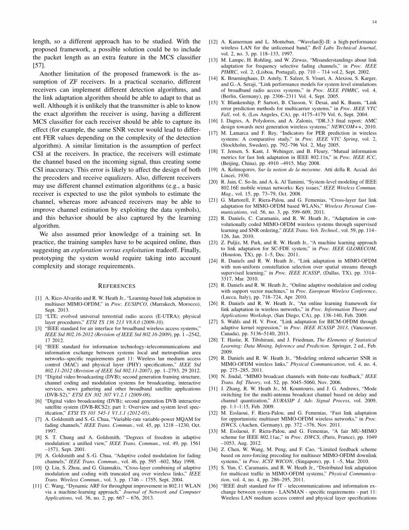
Figure 2: Analytical and empirical interference leakage perspatial stream
(1Lu
tr Cu,j
)for a two-user scenario. The
theoretical approximation is calculated using (26) and theclosed form expressions for the expected values (30) - (37).The simulation interference leakage was averaged over 100independent MIMO channels with independent complex Gaus-sian entries.
Note that the complexity of obtaining the error covariancematrix is similar to the complexity of recovering the matrixV from the quantized angles. Figure 2 shows the accuracy ofthe analytical approximation.
VI. MCS SELECTION
The MCS selection block consists of a function µ that takesas input the set of post-processing SNR values of user u andthe number of spatial streams Lu, and computes the higherMCS that meets the FER constraint for those SNR values,i.e.
µ (γu, Lu) = arg maxc∈C
η (c, Lu) subject to FER (γu, cu) ≤ p0.(39)
The post-processing SNR values are calculated by applyingthe approximations (21) and (26) in (4) to incorporate theinterference leakage estimate. An important observation is thatin (39) the rate is being maximized, not the throughput. Thereason is that for small values of p0, the feasible points meetη (c, Lu) (1− FER (γu, cu)) ≈ η (c, Lu). This approximationsimplifies the problem, since estimating the actual value ofFER (γu, cu) is not required, rather it is only necessary todiscriminate whether it is above the desired threshold p0 ornot.
We use a machine learning inspired approach to solve (39).Essentially, we classify features derived from the channel intothe highest MCS that meets the target FER constraint. Theclassifier is made up of individual classifiers that distinguishwhether a certain MCS and number of spatial streams aresupported by the current channel. Note that this is slightlydifferent from conventional machine learning in that there is atarget average error rate, whereas machine learning usually

8
W`,n = E
I`−1 ⊗G∗`,n
cosψ`,nG∗`,n − sinψ`,nG∗`,n
In−`−1 ⊗G∗`,n
sinψ`,nG∗`,n cosψ`,nG∗`,n
INtx−n ⊗G∗`,n
(33)
EG∗`,n =
I`−1
sin ε cos ψ`,nε
− sin ε sin ψ`,nε
In−`−1
sin ε sin ψ`,nε
sin ε cos ψ`,nε
INtx−n
(34)
E cosψ`,nG∗`,n =
cos ψ`,n sin εε I`−1
J`,ncos ψ`,n sin ε
ε INtx−n
(35)
with
J`,n =
ε+cos ε cos 2ψ`,n sin ε2ε − cos ε cos ψ`,n sin ε sin ψ`,n
εcos ψ`,n sin ε
ε In−`−1cos ε cos ψ`,n sin ε sin ψ`,n
εε+cos ε cos 2ψ`,n sin ε
2ε
(36)
and
E sinψ`,nG∗`,n =
sin ψ`,n sin εε I`−1
S`,nsin ψ`,n sin ε
ε INtx−n
(37)
with
S`,n =
cos ε cos ψ`,n sin ε sin ψ`,nε − ε−cos ε cos 2ψ`,n sin ε
2εsin ψ`,n sin ε
ε In−`−1ε−cos ε cos 2ψ`,n sin ε
2εcos ε cos ψ`,n sin ε sin ψ`,n
ε
. (38)
involves avoiding classification errors altogether. We willfollow a supervised learning approach to solve this problem,which includes two separated tasks: feature extraction andclassification.
A. Feature extraction
In machine learning, the curse of dimensionality is wellknown: the larger the dimension of the feature vector, theexponentially more data is required [51]. To reduce the di-mensionality of γu, we exploit insights made in [22] aboutperformance in coded bit interleaved MIMO-OFDM systems.In particular, it was recognized that performance was invariantto subcarrier ordering, i.e., FER (γu, cu) = FER (Πγu, cu),with Π any permutation matrix. Therefore, the reduced di-mension feature vector should be invariant to subcarrier or-dering. Similar to [22], we use a subset of the ordered SNRvalues as our feature vector. Define the ordered SNR vectorγu = [γu,1 . . . γu,NLu ]
T as a vector formed by ordering
the elements in γu in ascending order. For example, γu,idenotes the i-th smallest SNR value (among all carriers andspatial streams) of user u. We obtain our feature vector f byselecting a subset of the entries of γu. Other approaches fordimensionality reduction, like principal component analysis[52], may alternatively be applied, but in our simulations wedid not see a significant benefit.
B. Classification
The objective of the classification task is to estimate thehighest MCS supported by the channel, as characterized bythe feature vector f . Following a similar approach as in [25],we use a set of classifiers δc,L(f) to discriminate whether thecurrent channel will support transmission with MCS c andL spatial streams while meeting the FER constraint. Moreformally, given a set of M training samples {(γi, ptr,i)}Mi=1,with ptr,i the FER of the i-th channel, the input data for the

9
classifier is the set {(f i, νi)}Mi=1, with
νi =
{1 if ptr,i ≤ p0−1 if ptr,i > p0
(40)
and f i the subset of the ordered SNR of the i-th channel. Theclassifier is a function of the feature input vector that maps
δc,L : f → {−1, 1} . (41)
There are several ways to construct a classifier; we choose thepopular SVM. An SVM determines the class of a sample bythe use of linear boundaries (hyperplanes) in high dimensionalspaces. Operating in a high dimensional space is enabled bythe use of a Kernel function K(x1,x2) that maps x1 andx2 to vectors φ(x1) and φ(x2) lying in a Hilbert space, andperforms the inner product in that space 〈φ(x1), φ(x2)〉. TheKernel function K(x1,x2) has a very simple form for properlychosen φ. In many cases, perfect separation by a hyperplaneis not possible (or not desirable, since it would lead to non-smooth boundaries) and a penalization term is introduced totake into account the misclassified training samples. Formally,the classifier is
δc,L(x) = sign
(M∑
i=1
αiνiK (x, f i) + b
)(42)
where αi is obtained as the result of the optimization problem
minimize 12
∑Mi=1
∑Mj=1 αiαjK (f i, f j)−
∑Mi=1 αi
subject to∑Mi=1 νiαi = 0
0 ≤ αi ≤ C, i = 1, . . . , M(43)
and b can be obtained by solving δc,L(f i)νi = 1 for anytraining sample f i such that 0 < αi < C [28]. The parameterC has to be adjusted to trade off smoothness and trainingmisclassification rate. High values of C result in very irregularboundaries caused by very small training errors, and lowvalues of C result in large training errors caused by smoothboundaries. In this paper we use the radial basis functionkernel
K(x1,x2) = exp
(−‖x1 − x2‖2
ρ2
), (44)
where parameter ρ2 is used to tradeoff bias and variance: smallvalues of ρ tend to take into account only the nearby trainingpoints, leading to high variance classifiers, and large values ofρ result in biased results. The parameters ρ and C are selectedusing a cross-validation approach [28].
For a given number of streams Lu, the overall classifierchooses the MCS with a higher rate among those predicted tomeet the FER constraint. The MCS selection function µ (39)is implemented as
µ (γu, Lu) = arg maxc∈C{η (c, Lu)} s.t. δc,L(γu) = 1. (45)
VII. USER AND MODE SELECTION
Performing optimal user and mode selection requires anexhaustive search over all possible combinations of users andnumber of streams per user. To overcome this challenge, wepropose a greedy approach, similar to [37]–[39], where thestreams are added one by one until the utility function ν (t)does not increase. In each iteration, one spatial stream is addedto the user whose increment in the number of spatial streamsled to a higher throughput. The algorithm continues until themaximum number of spatial streams is reached, or when anincrement in the number of spatial streams lead to a lowersum rate.
An important observation is that the greedy algorithm is notfair, in the sense that a user could be assigned all the spatialstreams if it led to a a higher objective function, in our case thesum rate. The objective function, however, could be modifiedto encourage fairness. For example, metrics that are concavein the rates would give more utility to assigining spatialstreams to unscheduled users. This change in the objectivefunction does not require any other change in the user selectionalgorithm, or the other pieces of our link adaptation procedure.The entire proposed link adaptation algorithm is summarizedin Algorithm 1.
Algorithm 1 Link Adaptation Algorithm
Lu = 0 ∀uR ← 0while
∑Uu=1 Lu < Ntx do
for Each user u with Lu < Nrx,u doCalculate matrices Fv[n], Gv[n], Bv[n]for all users v, for the spatial streams set{L1, L2, . . . , Lu + 1, . . . , LK} following theprocedure in Section V.Calculate interference leakage Ru,j as in (23).Calculate post-processing SNR values γv∀v as in (4).cv ← µ (γv, Lv)∀v. {Calculate optimum MCS for allusers}tv ← η (cv, Lv)∀v {Calculate the corresponding rate}Ru ← ν (t) {Utility metric if we incremented Lu by1}
end forj ← arg maxu {Ru} {User whose increment in Lu leadsto a higher rate}if Rj ≥ R thenLj ← Lj + 1R ← Rj
elseStop algorithm.
end ifend while
VIII. SIMULATION RESULTS
To validate the performance of the proposed link adaptationmethod, we performed simulations using parameters from the

10
Table I: MCS in IEEE 802.11ac with the corresponding datarates in 20MHz channels [36].
MCS Rate (Mb/s)
BPSK 1/2 6.5
QPSK 1/2 13
QPSK 3/4 19.5
16-QAM 1/2 26
16-QAM 3/4 39
MCS Rate (Mb/s)
64-QAM 2/3 52
64-QAM 3/4 58.5
64-QAM 5/6 65
256-QAM 3/4 78
physical layer of IEEE 802.11ac. The studied scenario com-prises a 4-antenna transmitter communicating with three 2-antenna receivers over a 20MHz channel (52 OFDM carriers)with an 800ns guard interval. The frame length was set to 128bytes. Perfect CSI was assumed at the receiver and differentlevels of CSI at the transmitter. The FER constraint for thelink adaptation problem was set to p0 = 0.1. The set of MCSfor optimization with the associated data rate for one spatialstream is shown in Table I.
The training of the classifiers δc,L was performed as follows.The training set was generated in a single user setting with per-fect CSI by simulating different channels for all MCS and NSSvalues. For each of the channels, the complete transmit-receivechain was simulated, e.g. coding, interleaving, equalization,decoding. The resulting SNR γi values and FER ptr,i werestored for each of the channels. The channels were generatedin the time domain with a 4-tap MIMO channel with iidGaussian entries with 30 different noise levels, correspondingto SNR values between 5 and 50 dB. For each training sample,the feature vector f consisted on 4 equispaced SNR values(including the first and last ones) from the ordered SNR vectorγi. The class νi of each training sample was adjusted to −1if the measured FER was above the desired threshold, i.e.,ptr,i > p0, and 1 otherwise. We do not consider multiuser orlimited feedback CSI in the training set, since we assumedthat the SNR information γi was enough to predict the FERperformance, regardless of whether the SNR values are theresult of performing limited feedback BD precoding or not.
The parameters ρ and C of the SVM classifier were chosenbefore training the system. We followed the usual K-foldcross validation procedure [28] (with K = 4) to select theseparameters. The SVM was implemented with the LIBSVMsoftware package [53].
We compare the performance of the SVM classifier withan average SNR and an exponential effective SNR classifier.The training and the test sets were generated independently,each one containing 6000 samples. For each sample, theFER was estimated by simulating the transmission of 103
frames for each of the generated channels, so a small partof the classification errors may be caused by an imperfectFER estimation. This error, however, is expected to affect allthe classifiers in the same way. The average SNR classifierdiscriminates the class using a threshold γth on the averageSNR, designed to minimize the training set error. Formally,
the average SNR classifier is
δAv. SNRc,L (γ) = sign
(1
NLu
Lu∑
l=1
N∑
n=1
γl [n]− γth
). (46)
The exponential effective SNR consists on a generalized meanof the SNR values
γeff = − 1
βlog
(1
NLu
Lu∑
l=1
N∑
n=1
exp (−βγl [n])
)(47)
that is compared with a threshold γeff, th, designed to minimizethe training set error. The parameter β depends on the MCS,and is also selected to minimize the training set error. We canwrite the effective SNR classifier as
δEff. SNRc,L (γ) = sign (γeff − γeff,th) . (48)
In Table II we show the accuracy results for the tested clas-sifiers. We can see that the SVM classifier outperforms the av-erage and effective SNR classifiers, and in many cases the clas-sification error is below 1%. For example, for 16-QAM 1/2,L = 1, the SVM classifier misclassifies around 1 sample outof 200 (0.417%), whereas the average SNR classifier makesapproximately 20 times more errors (9.73%). In that case, theerror rate of the effective SNR classifier is 1.51%, approxi-mately 4 times more than the SVM classifier. The classificationgain with respect to the Av. / Eff. SNR classifier is calculatedas(ErrorAv. / Eff. SNR − ErrorSVM
)/ErrorAv. / Eff. SNR,
and in the 16-QAM 1/2 case for the Av. SNR classifier isapproximately 20−1
20 ≈ 0.95. This classification gain reflectsthe percentage of errors made by the average or effectiveSNR classifier that would be corrected by the SVM. Forexample, a classification gain of 100% means that the SVMclassifier is perfect, and a classification gain of 0% meansthat the SVM has the same accuracy as the average SNRclassifier. We can see that in some MCS the Eff. SNRclassifier outperforms the SVM classifier, but in average theSVM performs 22.34% better than the Eff. SNR classifier.The average gain with respect to the Av. SNR classifier ismuch higher, above 67%. This result confirms that SVM-basedlink adaptation algorithms outperform state-of-the-art effectiveSNR classifiers, currently used widely in LTE, among othercommunication systems [54].
Complete system simulations were run for three differentCSI levels at the transmitter: perfect CSI and limited feedbackCSI with (bψ = 5, bφ = 7) and (bψ = 4, bφ = 6). Simulationswere also run for the (bψ = 6, bφ = 8) case, the higher rateavailable in IEEE 802.11ac, but the results are not shownas they are indistinguishable from the perfect CSI ones. Inall cases a MU feedback was assumed (i.e., including SNRinformation of all carriers), even for (bψ = 4, bφ = 6), whichis only available for SU mode in IEEE 802.11ac. The misclas-sified samples, i.e., the cases where the selected MCS led toa FER value over the predefined threshold, were penalizedand computed as zero throughput. This penalization is setto remove the advantage of selecting an MCS with a higherthroughput, but without meeting the outage constraint, and is acommon procedure when evaluating link adaptation algorithms[22, Sec. V.D], [55, Eq. (3)]. The channels were generated

11
Table II: Classification errors and accuracy gain of the SVM classifier with respect to the Average and Eff. SNR classifier (allin %).
SVM Av. SNR Gain Av. SNR Eff. SNR Gain Eff. SNR
L=1 L=2 L=3 L=4 L=1 L=2 L=3 L=4 L=1 L=2 L=3 L=4 L=1 L=2 L=3 L=4 L=1 L=2 L=3 L=4BPSK 1/2 0.45 1.33 1.05 0.88 9.4 2.9 1.78 2.82 95.2 54.0 41.1 68.6 0.866 1.2 1.08 1.46 48.1 -11.1 3.08 39.8
QPSK 1/2 0.433 1.12 1 0.683 3.92 7.87 2.33 3.32 95.2 54.0 41.1 68.6 1.1 1.35 1.18 0.9 60.6 17.3 15.5 24.0
QPSK 3/4 1.43 3.57 4.78 2.08 9.22 6.38 6.7 3.78 84.4 44.1 28.6 44.9 2.75 1.4 3.35 2.83 47.9 -154 -42.8 26.5
16-QAM 1/2 0.417 0.6 1.22 0.8 9.73 4.11 1.97 2.45 95.7 85.4 38.1 67.3 1.51 1.58 1.68 1.8 72.5 62.0 27.7 55.6
16-QAM 3/4 1.58 3.87 3.63 1.9 7.63 7.15 4.92 3.28 79.3 45.9 26.1 42.1 3.07 3.63 3.1 2.7 48.4 -6.42 -17.2 29.6
64 QAM 2/3 0.433 1.5 1.66 1.15 4.5 5.11 3.31 2.36 90.3 70.6 49.7 51.4 1.72 2.52 2.33 2.87 74.8 40.4 28.6 59.9
64 QAM 3/4 1.03 2.68 3.05 2.05 6.53 6.1 5.47 3.12 84.2 56.0 44.2 34.2 2.57 3.28 3.08 4.13 59.7 18.3 1.08 50.4
64-QAM 5/6 0.783 1.85 1.57 2.33 7.87 6.38 2.82 5.67 90.0 71.0 44.3 58.8 2.57 3.03 1.88 3.01 69.5 39.0 16.8 22.6
Average 1.65 5.03 67.2 2.24 26.3
5 10 15 20 25 30 35 40 45 500
50
100
150
200
250
300
350Sum throughput with penalization
10 log(1/σ2
)
Throughput(M
b/s)
Perfect CSI
bψ = 5, bφ = 7
bψ = 4, bφ = 6
bψ = 5, bφ = 7 No Est
bψ = 4, bφ = 6 No Est
(a) Sum throughput.
5 10 15 20 25 30 35 40 45 50
10−2
10−1
100 Frame Error Rate
10 log(1/σ2
)
FER
Perfect CSI
bψ = 5, bφ = 7
bψ = 4, bφ = 6
bψ = 5, bφ = 7 No Est
bψ = 4, bφ = 6 No Est
(b) Frame error rate.
Figure 3: Simulation results for different feedback rates, with and without interference estimation. 4-tap Gaussian channelmodel.
independently from the training samples, but with the samestatistical distribution. The channels for the three receiverswere generated independently and with the same distribution,so fairness is automatically induced in this scenario. In otherscenarios with users with different average received power,fairness can be introduced by changing the objective function,as explained in Section IV.
Figure 3a illustrates the sum throughput as a function ofthe noise variance. As expected, in the perfect CSI case, thethroughput increases with the SNR, as the interuser interfer-ence is completely avoided in this setting, and lower noiselevels enable the use of higher rate MCS. For the limitedfeedback CSI we study two different cases. The first case, rep-resented by solid lines, is the result of following the completelink adaptation algorithm, including the interference estimationprocedure. The second case, in dashed lines, does not includethe interference estimation block (i.e., assumes Cu,j = 0),thus is overestimating the actual SNR. For the interferenceestimation case, we see that (bψ = 5, bφ = 7) follows the trendof the perfect CSI curve with a slightly lower throughputuntil an SNR value of around 35dB, and then flattens witha maximum throughput around 220Mb/s. Performance loss ismore significant with the lower rate feedback (bψ = 4, bφ = 6)for moderate SNR values, reaching an error floor around
190Mb/s in the interference limited regime. We can see that theperfect CSI curve flattens at 312Mb/s, which is the throughputof 4 streams using 256-QAM 3/4, the maximum rate MCS inTable I. If the interference estimation is not performed (thecurves tagged as No Est) then the results are dramaticallydifferent. At low SNR values, the evolution of these curvesis similar to the more sophisticated algorithm, as in thisregion the system is noise limited rather than interferencelimited. As the SNR increases, there is a huge degradationwith respect to the perfect CSI case. Performance is penalizedat high SNR where throughput decreases dramatically. Thisunexpected behavior is caused by the overestimation of theSNR due to the interuser interference that is not taken intoaccount, which causes the classifier to choose an MCS witha higher rate than the channel can support. This leads tomisclassified samples, leading to high FER values that drivethe throughput towards zero. From a learning perspective, thefeature set does not contain enough information to performthe adaptation. This information is implicitly included in theSNR values when performing interference estimation.
In Figure 3b, we plot the evolution of the FER with theaverage SNR. We can see that in the perfect CSI case aswell as in the cases where the interference is estimated,the FER constraint of 0.1 is always met. This result shows

12
0 5 10 15 20 25 30 35 400
0.1
0.2
0.3
0.4
0.5
0.6
0.7
0.8
0.9
1
10 log(1/σ2
)
Frequency
Perfect CSI
No Transm.
BPSK 1/2
QPSK 1/2
QPSK 3/4
16-QAM 1/2
16-QAM 3/4
64 QAM 2/3
64 QAM 3/4
64-QAM 5/6
256-QAM 3/4
0 5 10 15 20 25 30 35 400
0.1
0.2
0.3
0.4
0.5
0.6
0.7
0.8
0.9
1bψ = 4, bφ = 6
10 log(1/σ2
)
Frequency
Figure 4: Evolution of the frequency of the different MCS with the average SNR for the perfect CSI case and limited feedbackwith interference estimation.
0 5 10 15 20 25 30 35 400
0.1
0.2
0.3
0.4
0.5
0.6
0.7
0.8
0.9
1
10 log(1/σ2
)
Frequency
Perfect CSI
1 User
2 Users
3 Users
0 5 10 15 20 25 30 35 400
0.1
0.2
0.3
0.4
0.5
0.6
0.7
0.8
0.9
1bψ = 4, bφ = 6
10 log(1/σ2
)
Frequency
Figure 5: Evolution of the frequency of the number of users scheduled for MU transmission with the average SNR for theperfect CSI case and limited feedback with interference estimation.
the robustness of the proposed approach even with limitedfeedback. If the interference is not estimated, then the FERgrows up to 1 due to the mismatch between the selected MCSand the actual SNR values, which causes the throughput todecrease, as previously explained. The classifier is able tocorrectly perform MCS selection in a multiuser setting despitebeing trained in a single user scenario, thus showing also therobustness of the classifiers against changes on the channeldistribution. This plot shows the importance of performing theinterference estimation procedure.
In Figure 4, we plot the fraction of the selected MCSfor different SNR values, for both perfect CSI and limitedfeedback. In the perfect CSI case, the number of scheduledusers is usually low for low SNR values (the No Transmissionfrequency, representing the case where a user is not scheduledfor transmission, is quite high) and the MCS are robust, whilefor higher SNR the No Transmission frequency decreases andhigher rate MCS are employed for transmission. In the limitedfeedback case the behavior is similar to perfect CSI for lowSNR values, but for higher SNR the interuser interference
forces to use more robust MCS and approximately one thirdof the time the No Transmission MCS is selected.
Now we study the frequency of a given number of usersbeing selected in Figure 5. In the perfect CSI case the numberof users grows up to three (i.e., all users are scheduled mostof the time), while in the limited feedback case transmitsto only two users most of the time. The reason is that inthe limited feedback case the interuser interference increaseswith the scheduled number of users, which is the limitingfactor in the high SNR regime. The user selection algorithm isable to identify the suboptimality of an aggressive multiusertransmission by estimating the residual interuser interference.The effect of scheduling only two users out of three was alsoobserved in Figure 4, where for high SNR values the Notransmission MCS is selected 33% of the time. This partialscheduling of the users can lead to unfair scenarios wherethe maximization of the sum rate causes one user not to bescheduled. This behavior can be corrected by changing theobjective function of the LA problem, as explained in SectionIV.

13
5 10 15 20 25 30 350
50
100
150
200
250Sum throughput with penalization
10 log(1/σ2
)
Throughput(M
b/s)
Perfect CSI
bψ = 5, bφ = 7
bψ = 4, bφ = 6
bψ = 5, bφ = 7 No Est
bψ = 4, bφ = 6 No Est
(a) Sum throughput
5 10 15 20 25 30 35
10−2
10−1
100 Frame Error Rate
10 log(1/σ2
)
FER
Perfect CSI
bψ = 5, bφ = 7
bψ = 4, bφ = 6
bψ = 5, bφ = 7 No Est
bψ = 4, bφ = 6 No Est
(b) Frame Error Rate
Figure 6: Simulation results for different feedback rates, with and without interference estimation. TGac channel model B.Classifier trained with Gaussian channel model.
We also run simulations using TGac channel model B[56] to show the robustness of the proposed approach againstchanges in the environment or channel model. The classifieris the same as in the previous section, i.e., is trained with4-tap MIMO channels with iid Gaussian entries. The 802.11channel model B presents realistic characteristics not presentin the 4-tap channel, such as delay taps with different power,and correlation among antennas. The objective of this exper-iment is to show if the ordered SNR feature vector sufficesto characterize the performance of the system even in thepresence of a change in the environment. The throughput andframe error rate results are shown in Figure 6. We can see thatthe link adaptation algorithm is able to keep the FER underthe required threshold. Once again, interference estimation isshown to be necessary to correctly select the number of usersand MCS.
We compared the performance of the proposed adaptationprocedure with the same algorithm, but using an effectiveSNR and average SNR classifier instead of SVM. We runthe simulations under TGac channel model B, and assumingperfect CSI at the transmitter. The results are shown in Figure7. The average SNR classifier offers a bad performance, aspredicted by the results in Table II. The effective SNR has aslightly worse performance than SVM, especially at low SNRvalues. At moderate SNR values (around 20dB), SVM offersapproximately a 20% gain in throughput.
IX. CONCLUSION AND FUTURE WORK
In this paper, we presented a framework for link adaptationin multiuser MIMO-OFDM networks with limited feedbackinformation. The link adaptation problem is formulated as amaximization of the sum rate subject to a FER constraint.Focusing on the multiuser capabilities in IEEE 802.11ac, wedeveloped a data-driven algorithm that performs user selec-tion, mode selection, MCS selection and takes into accountlimited feedback information. We showed that estimating theinterference due to imperfect CSI is crucial to achieve a good
5 10 15 20 25 30 350
50
100
150
200
250Sum throughput with penalization
10 log(1/σ2
)
Throughput(M
b/s)
Perfect CSI SVM
Perfect CSI Eff. SNR
Perfect CSI Av. SNR 18%
50%
Figure 7: Comparison between SVM, Eff. SNR and Av. SNRclassifiers
performance in the multiuser MIMO setting. Depending on thefeedback rate, and by estimating the residual interference, thetransmitter is able to identify the error floor caused by mul-tiuser transmission in the high SNR regime. We conclude thatmachine learning classifiers can be used in a multiuser setting,even in limited feedback scenarios. Performing interferenceestimation, however, is crucial for the algorithm performance.The machine learning classifier is also shown to be robustto changes in the statistical distribution of the channel. Forexample, the information acquired in an open environment canbe used to effectively perform adaptation in an office setting,where more frequency selectivity is expected.
Future work includes incorporating more realistic systemaspects. For example, we assumed a constant codeword length,whereas in IEEE 802.11ac the codeword length can vary from1 to 65535 bytes, thus severely affecting the FER performance.It is not feasible to have a different classifier for every possible
14
length, so a different approach has to be studied. With theproposed framework, a possible solution could be to includethe packet length as an extra feature in the MCS classifier[57].
Another limitation of the proposed framework is the as-sumption of ZF receivers. In a practical scenario, differentreceivers can implement different detection algorithms, andthe link adaptation algorithm should be able to adapt to that aswell. Although it is unlikely that the transmitter is able to knowthe exact algorithm the receiver is using, having a differentMCS classifier for each receiver should be able to capture itseffect (for example, the same SNR vector would lead to differ-ent FER values depending on the complexity of the detectionalgorithm). A similar limitation is the assumption of perfectCSI at the receivers. In practice, the receivers will estimatethe channel based on the incoming signal, thus creating someCSI inaccuracy. This error is likely to affect the design of boththe precoders and receive equalizers. Also, different receiversmay use different channel estimation algorithms (e.g., a basicreceiver is expected to use the pilot symbols to estimate thechannel, whereas more advanced receivers may be able toimprove channel estimation by exploiting the data symbols),and this behavior should be also captured by the learningalgorithm.
We also assumed prior knowledge of a training set. Inpractice, the training samples have to be acquired online, thussuggesting an exploration versus exploitation tradeoff. Finally,prototyping the system would require taking into accountcomplexity and storage requirements.
REFERENCES
[1] A. Rico-Alvarino and R. W. Heath Jr., “Learning-based link adaptation inmultiuser MIMO-OFDM,” in Proc. EUSIPCO, (Marrakech, Morocco),Sept. 2013.
[2] “LTE; evolved universal terrestrial radio access (E-UTRA); physicallayer procedures,” ETSI TS 136 213 V8.8.0 (2009-10).
[3] “IEEE standard for air interface for broadband wireless access systems,”IEEE Std 802.16-2012 (Revision of IEEE Std 802.16-2009), pp. 1 –2542,17 2012.
[4] “IEEE standard for information technology–telecommunications andinformation exchange between systems local and metropolitan areanetworks–specific requirements part 11: Wireless lan medium accesscontrol (MAC) and physical layer (PHY) specifications,” IEEE Std802.11-2012 (Revision of IEEE Std 802.11-2007), pp. 1–2793, 29 2012.
[5] “Digital video broadcasting (DVB); second generation framing structure,channel coding and modulation systems for broadcasting, interactiveservices, news gathering and other broadband satellite applications(DVB-S2),” ETSI EN 302 307 V1.2.1 (2009-08).
[6] “Digital video broadcasting (DVB); second generation DVB interactivesatellite system (DVB-RCS2); part 1: Overview and system level spec-ification,” ETSI TS 101 545-1 V1.1.1 (2012-05).
[7] A. Goldsmith and S.-G. Chua, “Variable-rate variable-power MQAM forfading channels,” IEEE Trans. Commun., vol. 45, pp. 1218 –1230, Oct.1997.
[8] S. T. Chung and A. Goldsmith, “Degrees of freedom in adaptivemodulation: a unified view,” IEEE Trans. Commun., vol. 49, pp. 1561–1571, Sept. 2001.
[9] A. Goldsmith and S.-G. Chua, “Adaptive coded modulation for fadingchannels,” IEEE Trans. Commun., vol. 46, pp. 595 –602, May 1998.
[10] Q. Liu, S. Zhou, and G. Giannakis, “Cross-layer combining of adaptivemodulation and coding with truncated arq over wireless links,” IEEETrans. Wireless Commun., vol. 3, pp. 1746 – 1755, Sept. 2004.
[11] C. Wang, “Dynamic ARF for throughput improvement in 802.11 WLANvia a machine-learning approach,” Journal of Network and ComputerApplications, vol. 36, no. 2, pp. 667 – 676, 2013.
[12] A. Kamerman and L. Monteban, “Wavelan R©-II: a high-performancewireless LAN for the unlicensed band,” Bell Labs Technical Journal,vol. 2, no. 3, pp. 118–133, 1997.
[13] M. Lampe, H. Rohling, and W. Zirwas, “Misunderstandings about linkadaptation for frequency selective fading channels,” in Proc. IEEEPIMRC, vol. 2, (Lisboa, Portugal), pp. 710 – 714 vol.2, Sept. 2002.
[14] K. Brueninghaus, D. Astely, T. Salzer, S. Visuri, A. Alexiou, S. Karger,and G.-A. Seraji, “Link performance models for system level simulationsof broadband radio access systems,” in Proc. IEEE PIMRC, vol. 4,(Berlin, Germany), pp. 2306–2311 Vol. 4, Sept. 2005.
[15] Y. Blankenship, P. Sartori, B. Classon, V. Desai, and K. Baum, “Linkerror prediction methods for multicarrier systems,” in Proc. IEEE VTCFall, vol. 6, (Los Angeles, CA), pp. 4175–4179 Vol. 6, Sept. 2004.
[16] I. Dagres, A. Polydoros, and A. Zalonis, “DR.3.3 final report: AMCdesign towards next generation wireless systems,” NEWCOM++, 2010.
[17] M. Lamarca and F. Rey, “Indicators for PER prediction in wirelesssystems: A comparative study,” in Proc. IEEE VTC Spring, vol. 2,(Stockholm, Sweden), pp. 792–796 Vol. 2, May 2005.
[18] T. Jensen, S. Kant, J. Wehinger, and B. Fleury, “Mutual informationmetrics for fast link adaptation in IEEE 802.11n,” in Proc. IEEE ICC,(Beijing, China), pp. 4910 –4915, May 2008.
[19] A. Kolmogorov, Sur la notion de la moyenne. Atti della R. Accad. deiLincei, 1930.
[20] R. Jain, C. So-In, and A.-k. Al Tamimi, “System-level modeling of IEEE802.16E mobile wimax networks: Key issues,” IEEE Wireless Commun.Mag., vol. 15, pp. 73–79, Oct. 2008.
[21] G. Martorell, F. Riera-Palou, and G. Femenias, “Cross-layer fast linkadaptation for MIMO-OFDM based WLANs,” Wireless Personal Com-munications, vol. 56, no. 3, pp. 599–609, 2011.
[22] R. Daniels, C. Caramanis, and R. W. Heath Jr., “Adaptation in con-volutionally coded MIMO-OFDM wireless systems through supervisedlearning and SNR ordering,” IEEE Trans. Veh. Technol., vol. 59, pp. 114–126, Jan. 2010.
[23] Z. Puljiz, M. Park, and R. W. Heath Jr., “A machine learning approachto link adaptation for SC-FDE system,” in Proc. IEEE GLOBECOM,(Houston, TX), pp. 1–5, Dec. 2011.
[24] R. Daniels and R. W. Heath Jr., “Link adaptation in MIMO-OFDMwith non-uniform constellation selection over spatial streams throughsupervised learning,” in Proc. IEEE ICASSP, (Dallas, TX), pp. 3314–3317, Mar. 2010.
[25] R. Daniels and R. W. Heath Jr., “Online adaptive modulation and codingwith support vector machines,” in Proc. European Wireless Conference,(Lucca, Italy), pp. 718–724, Apr. 2010.
[26] R. Daniels and R. W. Heath Jr., “An online learning framework forlink adaptation in wireless networks,” in Proc. Information Theory andApplications Workshop, (San Diego, CA), pp. 138–140, Feb. 2009.
[27] S. Wahls and H. V. Poor, “Link adaptation for BICM-OFDM throughadaptive kernel regression,” in Proc. IEEE ICASSP 2013, (Vancouver,Canada), pp. 5136–5140, 2013.
[28] T. Hastie, R. Tibshirani, and J. Friedman, The Elements of StatisticalLearning: Data Mining, Inference and Prediction. Springer, 2 ed., Feb.2009.
[29] R. Daniels and R. W. Heath Jr., “Modeling ordered subcarrier SNR inMIMO-OFDM wireless links,” Physical Communication, vol. 4, no. 4,pp. 275–285, 2011.
[30] N. Jindal, “MIMO broadcast channels with finite-rate feedback,” IEEETrans. Inf. Theory, vol. 52, pp. 5045–5060, Nov. 2006.
[31] J. Zhang, R. W. Heath Jr., M. Kountouris, and J. G. Andrews, “Modeswitching for the multi-antenna broadcast channel based on delay andchannel quantization,” EURASIP J. Adv. Signal Process, vol. 2009,pp. 1:1–1:15, Feb. 2009.
[32] M. Esslaoui, F. Riera-Palou, and G. Femenias, “Fast link adaptationfor opportunistic multiuser MIMO-OFDM wireless networks,” in Proc.ISWCS, (Aachen, Germany), pp. 372 –376, Nov. 2011.
[33] M. Esslaoui, F. Riera-Palou, and G. Femenias, “A fair MU-MIMOscheme for IEEE 802.11ac,” in Proc. ISWCS, (Paris, France), pp. 1049–1053, Aug. 2012.
[34] Z. Chen, W. Wang, M. Peng, and F. Cao, “Limited feedback schemebased on zero-forcing precoding for multiuser MIMO-OFDM downlinksystems,” in Proc. ICST WICON, (Singapore), pp. 1 –5, Mar. 2010.
[35] S. Yun, C. Caramanis, and R. W. Heath Jr., “Distributed link adaptationfor multicast traffic in MIMO-OFDM systems,” Physical Communica-tion, vol. 4, no. 4, pp. 286–295, 2011.
[36] “IEEE draft standard for IT - telecommunications and information ex-change between systems - LAN/MAN - specific requirements - part 11:Wireless LAN medium access control and physical layer specifications

15
- amd 4: Enhancements for very high throughput for operation in bandsbelow 6ghz,” IEEE P802.11ac/D3.0, June 2012, pp. 1–385, jun 2012.
[37] G. Dimic and N. Sidiropoulos, “On downlink beamforming with greedyuser selection: performance analysis and a simple new algorithm,” IEEETrans. Signal Process., vol. 53, pp. 3857–3868, Oct. 2005.
[38] M. Kobayashi and G. Caire, “Joint beamforming and scheduling for aMIMO downlink with random arrivals,” in Proc. IEEE ISIT, (Seattle,WA), pp. 1442–1446, July 2006.
[39] R. Chen, Z. Shen, J. Andrews, and R. W. Heath Jr., “Multimodetransmission for multiuser MIMO systems with block diagonalization,”IEEE Trans. Signal Process., vol. 56, pp. 3294–3302, July 2008.
[40] Cisco Systems, “White paper: 802.11ac: The fifth generation of wi-fi,”2012.
[41] H. Kim, K. Kim, Y. Han, and S. Yun, “A proportional fair schedulingfor multicarrier transmission systems,” in Proc. IEEE VTC-Fall, (LosAngeles, CA), pp. 409–413 Vol. 1, Sept. 2004.
[42] Q. Spencer, A. Swindlehurst, and M. Haardt, “Zero-forcing methods fordownlink spatial multiplexing in multiuser mimo channels,” IEEE Trans.Signal Process., vol. 52, pp. 461–471, Feb. 2004.
[43] M. Sadek, A. Tarighat, and A. Sayed, “A leakage-based precodingscheme for downlink multi-user MIMO channels,” IEEE Trans. WirelessCommun., vol. 6, pp. 1711 –1721, may 2007.
[44] Z. Shen, R. Chen, J. G. Andrews, R. W. Heath Jr., and B. L. Evans, “Lowcomplexity user selection algorithms for multiuser MIMO systems withblock diagonalization,” IEEE Trans. Signal Process., vol. 54, pp. 3658–3663, Sept. 2006.
[45] G. Golub and C. Van Loan, Matrix computations. Johns HopkinsUniversity Press, 1996.
[46] J. Roh and B. Rao, “Efficient feedback methods for MIMO channelsbased on parameterization,” IEEE Trans. Wireless Commun., vol. 6,pp. 282 –292, Jan. 2007.
[47] Y. Linde, A. Buzo, and R. Gray, “An algorithm for vector quantizerdesign,” IEEE Trans. Commun., vol. 28, pp. 84 – 95, Jan. 1980.
[48] M. A. Sadrabadi, A. K. Khandani, and F. Lahouti, “Channel feedbackquantization for high data rate MIMO systems,” IEEE Trans. WirelessCommun., vol. 5, pp. 3335 –3338, Dec. 2006.
[49] H. V. Henderson and S. Searle, “The vec-permutation matrix, the vecoperator and Kronecker products: A review,” Linear and multilinearalgebra, vol. 9, no. 4, pp. 271–288, 1981.
[50] R. Zamir and M. Feder, “On lattice quantization noise,” in Proc. DCC,(Snowbird, UT), pp. 380 –389, Mar. 1994.
[51] G. Hughes, “On the mean accuracy of statistical pattern recognizers,”IEEE Trans. Inf. Theory, vol. 14, pp. 55 – 63, Jan. 1968.
[52] S. Wold, K. Esbensen, and P. Geladi, “Principal component analysis,”Chemometrics and Intelligent Laboratory Systems, vol. 2, no. 1-3, pp. 37– 52, 1987. Proceedings of the Multivariate Statistical Workshop forGeologists and Geochemists.
[53] C.-C. Chang and C.-J. Lin, “LIBSVM: A library for support vectormachines,” ACM Transactions on Intelligent Systems and Technology,vol. 2, pp. 27:1–27:27, 2011. Software available at http://www.csie.ntu.edu.tw/∼cjlin/libsvm.
[54] T. Tao and A. Czylwik, “Performance analysis of link adaptation in LTEsystems,” in International ITG Workshop on Smart Antennas, pp. 1–5,2011.
[55] Y.-S. Choi and S. Alamouti, “A pragmatic PHY abstraction techniquefor link adaptation and MIMO switching,” IEEE J. Sel. Areas Commun.,vol. 26, no. 6, pp. 960–971, 2008.
[56] TGac Channel Models Special Committee, “TGac channel model ad-dendum,” IEEE 802.11-09/0308r0, May 2009.
[57] A. Rico-Alvarino and R. W. Heath Jr., “Link adaptation in MIMO-OFDM with practical impairments,” in Proc. Asilomar SSC, (PacificGrove, CA), Nov. 2013.
Alberto Rico-Alvarino (S’12) received theTelecommunications Engineering degree from theUniversity of Vigo, Galicia, Spain, in 2010 and theM.S. degree in electrical engineering from the sameuniversity in 2012. He is currently working towardsthe Ph.D. degree with the University of Vigo inthe area of signal processing in communications.In 2012-2013 he visited the Wireless Networkingand Communications Group at The University ofTexas at Austin, funded by a Pedro Barrie de laMaza graduate scholarship. He was an intern in
Qualcomm Inc. (San Diego, CA) during the summer of 2013, where heworked in advanced receiver algorithms for LTE-A. A. Rico-Alvarino is arecipient of the best professional paper award at AIAA ICSSC 2012. Hisresearch focuses on cognitive radio, link adaptation in MIMO-OFDM andsatellite communications, and wireless communications in general.
Robert W. Heath Jr. (S’96 - M’01 - SM’06- F’11) received the B.S. and M.S. degrees fromthe University of Virginia, Charlottesville, VA, in1996 and 1997 respectively, and the Ph.D. fromStanford University, Stanford, CA, in 2002, all inelectrical engineering. From 1998 to 2001, he was aSenior Member of the Technical Staff then a SeniorConsultant at Iospan Wireless Inc, San Jose, CAwhere he worked on the design and implementationof the physical and link layers of the first commercialMIMO-OFDM communication system. Since Jan-
uary 2002, he has been with the Department of Electrical and ComputerEngineering at The University of Texas at Austin where he is a Cullen Trustfor Higher Education Endowed Professor, and is Director of the WirelessNetworking and Communications Group. He is also President and CEO ofMIMO Wireless Inc. and Chief Innovation Officer at Kuma Signals LLC. Hisresearch interests include several aspects of wireless communication and sig-nal processing: limited feedback techniques, multihop networking, multiuserand multicell MIMO, interference alignment, adaptive video transmission,manifold signal processing, and millimeter wave communication techniques.
Dr. Heath has been an Editor for the IEEE Transactions on Communication,an Associate Editor for the IEEE Transactions on Vehicular Technology,lead guest editor for an IEEE Journal on Selected Areas in Communicationsspecial issue on limited feedback communication, and lead guest editor foran IEEE Journal on Selected Topics in Signal Processing special issue onHeterogenous Networks. He currently serves on the steering committee forthe IEEE Transactions on Wireless Communications. He was a member ofthe Signal Processing for Communications Technical Committee in the IEEESignal Processing Society and is a former Chair of the IEEE COMSOCCommunications Technical Theory Committee. He was a technical co-chairfor the 2007 Fall Vehicular Technology Conference, general chair of the 2008Communication Theory Workshop, general co-chair, technical co-chair andco-organizer of the 2009 IEEE Signal Processing for Wireless Communica-tions Workshop, local co-organizer for the 2009 IEEE CAMSAP Conference,technical co-chair for the 2010 IEEE International Symposium on InformationTheory, the technical chair for the 2011 Asilomar Conference on Signals,Systems, and Computers, general chair for the 2013 Asilomar Conferenceon Signals, Systems, and Computers, founding general co-chair for the 2013IEEE GlobalSIP conference, and is technical co-chair for the 2014 IEEEGLOBECOM conference.
Dr. Heath was a co-author of best student paper awards at IEEE VTC 2006Spring, WPMC 2006, IEEE GLOBECOM 2006, IEEE VTC 2007 Spring,and IEEE RWS 2009, as well as co-recipient of the Grand Prize in the 2008WinTech WinCool Demo Contest. He was co-recipient of the 2010 and 2013EURASIP Journal on Wireless Communications and Networking best paperawards, the 2012 Signal Processing Magazine best paper award, a 2013 SignalProcessing Society best paper award, and the 2014 EURASIP Journal onAdvances in Signal Processing best paper award. He was a 2003 Frontiers inEducation New Faculty Fellow. He is also a licensed Amateur Radio Operatorand is a registered Professional Engineer in Texas.