learning objectives - autodeskaucache.autodesk.com/au2012/...au_2012_class_hando… · web...
TRANSCRIPT
Mass Lab: Building Masses So They Don't Blow UpKelly Cone - Beck GroupMarcello Sgambelluri, John Martin Structural Engineers
AB3074-L
Want to learn how to make a bullet-proof mass that takes a hexing and keeps on flexing? (Not much rhymes with flexing, okay?) We’ll cover some techniques to help simplify that complex mass you need for your building design. Complex curves? Lofts? Revolves? Want to join them all together and still have them flex? After this class, you’ll know how to make a mass that even your newest Autodesk® Revit® software convert can’t break. Why does a bulletproof mass matter so much? Because once you start making building elements off that mass, if it breaks, you’ll have to start over from scratch. Hasta la vista to all your customizations and hosted components. So, bring your math hat and your sketchbook and let’s make some masses.
Learning ObjectivesAt the end of this class, you will be able to:
Learn techniques for making complex building forms parametric
Learn tricks to make your parametric mass foolproof, (well, at least mostly)
Understand how the conceptual massing editor relates to building elements
Define the workflow required to keep masses viable through the DD and CD phases
About the SpeakersKelly Cone: Kelly joined the Beck Group as an architectural intern and has been focusing on technology and implementation of BIM practices and software since. In his current role as Innovations Director, he oversees the implementation of BIM technology and processes nationwide in our Architecture, Estimating, Real Estate, and Construction groups. He is responsible for ensuring that the tools and technologies employed further Beck’s commitment to integrating the design and construction disciplines, and advance our efforts at making our buildings more sustainable. Kelly is also deeply involved in the Building Information Modeling community. He has spoken at numerous national and international BIM conferences and blogs about the future of BIM and the Revit Platform on RevitFutures.blogspot.com
Marcello Sgambelluri: Marcello is the BIM Director at John A. Martin & Associates Structural Engineers in Los Angeles, CA. He has been using Autodesk products for over 15 years including AutoCAD, 3ds Max, and Revit. He is a member of the ASCE-SEI BIM committee and continually speaks at structural professional conferences across the country. Marcello teaches classes regularly at Autodesk University and the Revit Technology conference that focuses on free form modeling in Revit and he beta tests the yearly releases of Revit. He has worked on many projects that incorporated complex geometry including the Walt Disney Concert Hall in Los Angeles, CA, the Stata Center at MIT, and the Tom Bradley International Terminal Expansion at the LAX. Marcello received B.S. and M.S. degrees in Civil Engineering and is a licensed Civil and Structural Engineer

Insert Class Title as per Title Page
Class Outline:We are going to spend a few minutes talking about what comes before you start working on the family, and then jump into the exercises!
Intro (7M) Family Planning (6M) Formulas (2M) Placement Rigs (15M) Geometry Rigs (15M) Building Masses from Rigs (15M) Using Masses in the Project Environment (15M) Q&A (15M)
Family PlanningBuilding any complex family requires a little forethought. Anyone with a lot of experience building families already has their own “way” of planning. I like to use mind maps. Marcello likes to think about it while he drives. As long as you have a way, that’s a good thing. If you don’t, you’d better figure out how you want to start…
Understand WHAT you’re modelingIt is critical when modeling complex forms that you understand the geometry you are trying to model. Part of that is understanding what to model it with. Can you model it with an extrusion and some voids or do you need to use a loft? What are the fundamental elements required to make those forms in Revit? (An extrusion is a profile plus extrusion distance, a loft is a number of located profiles along a path.) The other part is actually understanding the form itself. Did you know a concentric ellipse does not have a constant offset all the way around it? If you take an ellipse, offset it, and then raise one profile above the other and create form the resultant shape cannot be rationalized into flat panels. If you create a concentric ellipse by scaling the major and minor axes, offset it, and then raise it up you can rationalize it to flat panels. Understanding the actual geometry can have a huge impact on the cost of what you design.
Understand what you’re DOING with it“Begin with the end in mind.” This is critical for any family content you are making in Revit, but even more so for masses. Do you want to get floor area faces, energy analysis, and volume calculations? It has to be a solid. If all you want is a face to map a curtain system to, a surface is just fine. Is it ever going to change? If not, who needs parameters? If so, you had better think about how it might change and how you can set it up to allow that change without starting over – otherwise your hard work in the project environment will be lost.
2

Insert Class Title as per Title Page
Make a plan for how it will be executed…If you understand the form and how to make it and you know what you need it to support downstream then you’re ready to make yourself a mass. But, execution is critical. We are in the profession of making plans for other people to use to build actual buildings. That doesn’t mean we don’t need plans ourselves. However you like to, make a plan for what kind of families you need, whether they need to be shared or not, what kind of parameters you want and if they need to be shared or not, and even how you want users to interact with them if they’re for everyone to use. Planning well can eliminate or reduce rework later.
Nesting and SharingConcepts like Nesting are equally important in masses, although shared nested masses aren’t as useful since mass floors and other properties of masses are at the instance level and therefore can’t be changed directly.
FormulasSince formulas have been well covered by other speakers in previous years and there is little new in 2013 that impacts our abilities to make formulaic constraints and controls; we will not be covering this topic in depth. Instead, I’ll refer you to some great resources to help you find your way with formulas in the various family editor environments. There are a few headings worth addressing as they relate to the main topic. In addition to controlling geometry, formulas can be used to prevent end users from making mistakes that might blow you mass to smithereens…
Formulas to limit resultsFormulas can be used to limit the results of certain operations regardless of user entry. Examples of this include using conditional statements and a second parameter controlling an array to prevent users inputting 1 as a number of an array and having it break the family. In this case, the formula ignores the 1 and uses 2 as the array number thanks to the conditional statement. Likewise, formulas can be used to give an end user an available range in which a value is reasonable. Input outside that range (1 to 100 for instance) can be ignored. Conditional statements are very useful to prevent users from inputting something that cannot be resolved due to the limitations of the geometry that an end user may not understand.
Formulas to control user interactionFormulas can also be used to control how users interact with certain geometry. Conditional statements can be used to tie a checkbox to multiple parameters/outcomes. Logic operands like AND/NOT/OR can be used to create a poor man’s toggle (tying multiple checkboxes together in opposition or in kind). You can simplify complex interactions using formulas while preventing unintended input that could break a family.
Formulas to prevent unintentional editsFormulas can be used to prevent people from editing parameters that would otherwise be open to manipulation. You can add a parameter with a hardcoded value of “0” in the formula field, and then use that parameter as an operator in another parameter’s simple formula to prevent the end user from being able to edit that parameter in the project environment. So, if you don’t want people inputting radius but do want them inputting diameter, creating a formula like Radius = Diameter/2 will allow the end user to edit either value. Adding = Diameter/2 + Zero locks the formula driven parameter as being uneditable in the project environment. Only the Diameter field is now available.
3

Insert Class Title as per Title Page
Resources:Since we don’t have time in this class to teach you a lot about resources, we have provided some helpful links to get you going on your own. We’ve also included the handout from Fuzzy Math from AU 2010 in the class materials as a reference.
Autodesk Revit Help Wiki – http://wikihelp.autodesk.com/Revit/enu/2013 Wikipedia can help with a lot of math questions – http://www.wikipedia.org If you need help solving an equation - http://www.wolframalpha.com/
Placement RigsRigs are a fancy way of saying “pre made things to make setting up a parametric relationship easier”. In a broad sense, the primary takeaway we want you to leave with is the concept of using rigs in your family making. There are different types of rigs, for the purpose of this class we’ll be talking about Placement and Geometry rigs. The primary differentiator is that placement rigs are used to place geometry while geometry rigs are used to create geometry. We’re going to get started with a placement rig.
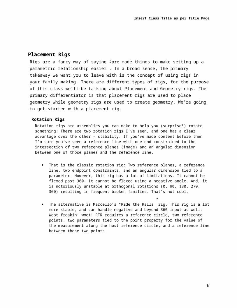
Rotation RigsRotation rigs are assemblies you can make to help you (surprise!) rotate something! There are two rotation rigs I’ve seen, and one has a clear advantage over the other – stability. If you’ve made content before then I’m sure you’ve seen a reference line with one end constrained to the intersection of two reference planes (image) and an angular dimension between one of those planes and the reference line.
That is the classic rotation rig: Two reference planes, a reference line, two endpoint constraints, and an angular dimension tied to a parameter. However, this rig has a lot of limitations. It cannot be flexed past 360. It cannot be flexed using a negative angle. And, it is notoriously unstable at orthogonal rotations (0, 90, 180, 270, 360) resulting in frequent broken families. That’s not cool.
The alternative is Marcello’s “Ride the Rails” rig. This rig is a lot more stable, and can handle negative and beyond 360 input as well. Woot freakin’ woot! RTR requires a reference circle, two reference points, two parameters tied to the point property for the value of the measurement along the host reference circle, and a reference line between those two points.
4

Insert Class Title as per Title Page
Exercise 1: Building the Ride the Rails rig and using it to place a mass componentWe will use the ride the rails rig to place a rotating mass component in this example.
As shown above in the rotation rig, the Ride the Rail method does not use an angular dimension to control the angle of the hosting reference line. It uses the power of the reference point to “ride” the “rail” of the circle or curve to control the angle.
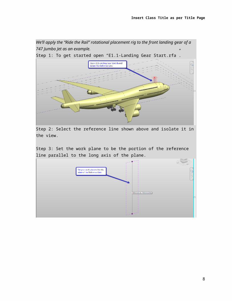
We’ll apply the “Ride the Rail” rotational placement rig to the front landing gear of a 747 Jumbo Jet as an example.
5
Insert Class Title as per Title Page
Step 1: To get started open “E1.1-Landing Gear Start.rfa”.
Step 2: Select the reference line shown above and isolate it in the view.
Step 3: Set the work plane to be the portion of the reference line parallel to the long axis of the plane.
6

Insert Class Title as per Title Page
Step 4: Draw a reference circle at the end of the isolated reference line.
Step 5: Place two point anywhere along the circle.
Step 6: Select both points and change the Measurement Type property to “Angle”.
7
Insert Class Title as per Title Page
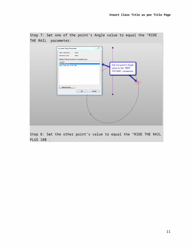
Step 7: Set one of the point’s Angle value to equal the “RIDE THE RAIL” parameter.
Step 8: Set the other point’s value to equal the “RIDE THE RAIL PLUS 180”.
8

Insert Class Title as per Title Page
Step 9: Select both points again and hit the Spline Through Points option in the Ribbon for creating model lines. Select the new line and check the Is Reference parameter to make it a reference line.
Congratulations! The Ride The Rail rotation rig is complete! Now we can place the landing gear on our new rig.
Step 10: Drag the type name of the Front Landing Gear.rfa into the view to create a new instance of the family.
9

Insert Class Title as per Title Page
Step 11: Before you place it, select to pick a reference plane to place the component on.
Step 12: Select this part of the reference line below to host the component on.
10
Insert Class Title as per Title Page
Step 13: Place your landing gear at the middle of the reference line (midpoint snap helps). You may need to flip the orientation to the workplane to get it pointing down.
Step 14: Before you flex your rig, set the work plane back to Level 1.
This is another bug that recently surfaced where the component won’t remember its orientation to its workplane in some situations when that workplane remains selected when you first flex a family. It will get fixed soon and this step won’t be necessary.
11

Insert Class Title as per Title Page
Step 15: Flex away. You can type in any value into a Ride The Rails rig. Negative angles, angles beyond 360, etc… Give it a good flexing.
Tip - Placement rigs can be created in the host family directly, or can be created as nested families. The best method really depends on the complexity of the host family and how much interaction between the various moving parts you can manage.
Coordinate RigsCoordinate Rigs allow you to host an object on one, two, or three axes and then control the location of that object using standard coordinate values (including negative numbers). The most common coordinate rig is a single axis Cartesian rig. (Gibberish?) If you’ve ever made two reference planes, one above an origin point and one below the origin point, dimensioned from the origin to plane one, and then from plane one to plane two. And tied a negative and positive parameter to the two dimensions, added an input parameter and written conditional formulas so that an end user can input a positive or negative value and have the object flex accordingly, then you’ve made one of these. (Run on sentence? Phbbbbt. I claim creative license...) There are a couple of types of coordinate rigs:
Cartesian Rigs can be made on one, two, or three axes (or more actually if you can come up with a good use case). So, you can have +/-X, +/-Y, and +/-Z off of any defined “origin” for your placement rig.
12

Insert Class Title as per Title Page
Exercise 2: Building a basic 1D Cartesian rigWe are using the Cartesian rig to control the location of the wings along the fuselage +/- from the actual location of the wings.
Step 1: To get started, open “E2.1-Wings Start.rfa” and go to the Level 5 Floor Plan.
Step 2: Create one reference plane and align it to the reference from the Wings.rfa family. Do not lock it. However, pin the reference plane after it is aligned. You’ve created the origin for your rig.
Step 3: Create two additional reference planes, one on either side of the origin plane.
13

Insert Class Title as per Title Page
Step 4: Dimension from your origin reference plane to the plane above it, then dimension from that reference plane to the reference plane below the origin. These dimensions will control your rig.
Step 5: Map the dimensions to parameters as shown below:
14

Insert Class Title as per Title Page
Step 6: Align the same reference you previously matched with your origin to the negative value reference plane (the one below the origin). Lock it.
Step 7: Go to Family Types and type in the following formulas into the parameters below:- Positive Offset (default) = if(not(Wing Location < 0'), abs(Wing Location), 0')- Negative Offset (default) = if(Wing Location < 0', abs(Wing Location), 0')
After you’ve done that, hit Apply.
You’ll notice your wings have moved back into the correct spot!
15

Insert Class Title as per Title Page
Step 8: Flex the rig to make sure it works! Enter positive or negative values into the “Wing Location” parameter. No problems.
16
Insert Class Title as per Title Page
Polar Rigs can be made to locate items based on polar coordinate inputs. Woo hoo! Likewise, you can define multiple planes upon which to locate polar origins which would allow you to create spherical mappings, or combine a polar rig with a Cartesian rig to create a cylindrical mapping.
There are some other mathematically defined coordinate systems you could theoretically replicate in Revit – I just can’t think of why you’d want to so they’ll remain unnamed.
Vector RigsVector rigs are different from coordinate or rotation rigs in that they allow you define a direction and then use that direction and length to drive the placement of elements. This is particularly useful for placing elements that (gasp) are directional! The classic example is the line based family that comes OOTB with Revit. The big advantage it has is that Revit “knows” to let you place it by clicking twice in the project environment. But, don’t let that slow you down. You can create your own vector rigs as well, or go really wild and use adaptive components to define multiple vectors. There are really three types of vector rigs in Revit:
The simplest form of a vector rig is a reference line. Using a reference line you can create a plane for hosting other elements that moves as the line’s direction or length changes. Again, what makes your use of a reference line a vector rig is if the length or direction of the line impacts what you’re placing on it.
Line based families (face or workplane based). Don’t worry, these can be hosted into a Mass family as long as they are an accepted category like Generic Model. Yay! These can be used to make a surface or a line on which you can host other elements in the host family.
Adaptive Component families. These can be a mass or another acceptable category and be hosted into another Mass family. The big advantage here is that you can define multiple vectors to place elements by, not just one! Again, you’ll typically create a surface or line in the AC family that can be used to host elements on in the host family.
Manual vector rigs. Need a curved vector to drive the location of elements along a curved path, you can manually achieve this by controlling the second (or third/fourth/fifth/etc…) point using parameters (or a coordinate placement rig). You’ll have a single placement point in the project, but you can move the other points with those parameters and even create symbolic or model geometry to represent additional points in the project environment.
Geometry RigsMuch like placement rigs, geometry rigs are here to make your life simpler. Geometry rigs can be as complex or as simple as you want, and can be static or parametric to suit your needs. Parametric rigs have the advantage of being more flexible and being controllable from the host families or even the project via mapping their parameters.
Workplane Based Profile RigsThe simplest geometry rigs are typically profiles. In the massing form editor, most of the shapes you can make require at least one profile. These can be closed or open depending on whether you want a surface or a solid form. A profile can be as simple as a single line, however something that simple
17

Insert Class Title as per Title Page
doesn’t usually justify a geometry rig. Rigs are great at taking something complex and giving you a way to break it down into manageable chunks.
A great example of a profile rig is a parametric ellipse. A complex form lofted out of multiple ellipses can result in a very complex and muddled family if it is all done in the host family. By taking the elliptical building block and breaking it out as a workplane based profile family, you’re removing 2X the number of constraints as you have profiles from the host family. Simplifying the host has a lot of benefits. Less unintended constraint interactions (from automatic sketch dimensions), better reliability in flexing, and you are making those 2 constraints per ellipse once – and can flex it, test it, and build in controls to prevent it breaking only once as well. This saves you time, and makes your resultant family even more reliable. Reliability is good if you’re going to base building geometry from the masses you’re making.
Typically, I use a couple of different types of workplane based profiles in my mass families depending on what I’ll be using them for:
Generic Model Workplane Based families can be advantageous if you’re planning on using those same profiles in the project environment for things like documentation. The example shown below is from a project with a complex elliptical void subtracted from the middle of a building mass to create a courtyard. Given Revit’s proclivity to cut the walls around the floor plans at the cut plane height (+1.5M in this case) and our need to dimension the sloped walls at the floor line and not the cut height, we embedded this generic model family into the mass as a shared nested component so we could dimension the major and minor axes as well as the focal points and center point that were being used to create the mass instead of relying upon detail lines or other means of faking the various measurements. There are a number of categories that can be loaded into a mass family, so it may be better to pick a specific category (like furniture?) if the documentation goals are better served by being specific.
Mass Workplane Based families are usually best when you want the profiles to vanish in the project environment along with the mass itself. They are also more flexible (massing editor instead of the traditional family editor) so you can technically accomplish some things that are more difficult with a generic model or other component family category.
18
Insert Class Title as per Title Page
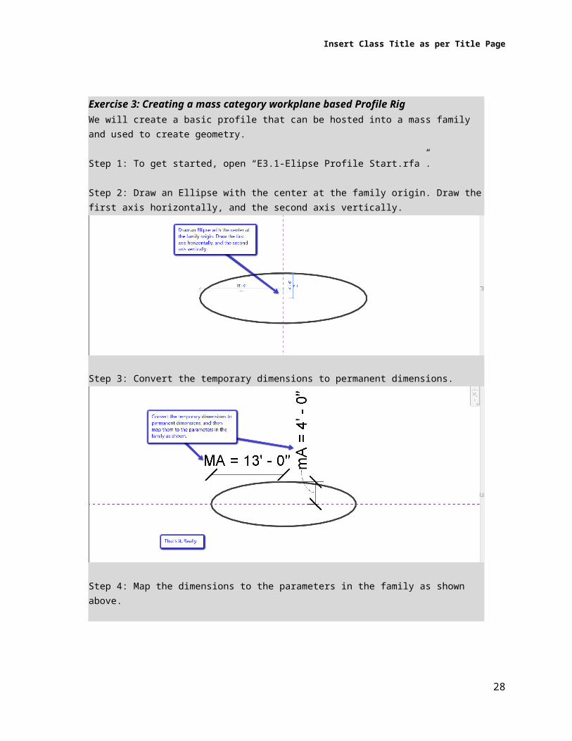
Exercise 3: Creating a mass category workplane based Profile RigWe will create a basic profile that can be hosted into a mass family and used to create geometry.
Step 1: To get started, open “E3.1-Elipse Profile Start.rfa”.
Step 2: Draw an Ellipse with the center at the family origin. Draw the first axis horizontally, and the second axis vertically.
Step 3: Convert the temporary dimensions to permanent dimensions.
Step 4: Map the dimensions to the parameters in the family as shown above.
19

Insert Class Title as per Title Page
Adaptive Component Surface RigsAdaptive Component Based geometry rigs are a niche use case. Usually, profiles need to be flat to create forms, the exception being surfaces. If flat is what you need, it is usually easier to use one of the two methods above. For certain form making though you may want to create a multi-point adaptive component family with linework in it to place as a basis for forming surfaces. Certain repetitive, rule-driven surfaces can be simplified by putting formulas into the Adaptive Component family so that placing them repeatedly in a mass provides more consistent results (image?). Also, Adaptive Components can be placed on complex surfaces, so you could then map complex, rule driven surfaces onto another curved surface – which would be pretty cool.
Building Masses from RigsSo, you’ve built a few rigs. How about creating some forms using those rigs already? We’re going to use a couple of examples to show how you can use the tricks above to make some pretty cool masses that are very flexible and very hard to break. Note, “very hard to break” means you have to do something pretty absurd to break it – not that you can’t break it by doing something absurd. I’m talking to that person in the back row who is about to make a 747 taller than it is long at one single point along its fuselage…
Using Profile Rigs to create formsUsing profile rigs to create forms is pretty simple. Most of the time, all you have to do is pick the profile and hit create form. This works just like selecting model lines or reference lines in the host family to create a form, except the model lines in the nested profile family never vanish on you. In some cases, you’ll have to tab select to get to the profile or even individual lines within the profile to get the create form button to activate. This usually has to do with the complexity of the profile and whether Revit can easily determine if it is a closed loop or not The rules are the same. Single profile = extrusion. Profile + perpendicular intersecting path = Sweep. Profile + planar path = revolve. Two profiles = Blend. More than two profiles = Loft. More than two profiles and a path that passes through each profile perpendicular to the profile = swept blend. You get the picture.
Exercise 4: Creating a mass form from hosted ProfilesWe will use multiple nested elliptical profiles to create the fuselage of the 747 Jumbo Jet.
Step 1: To get started, open “E4.1-Fuselage Start.rfa” and zoom in on the front of the plane.
20

Insert Class Title as per Title Page
21

Insert Class Title as per Title Page
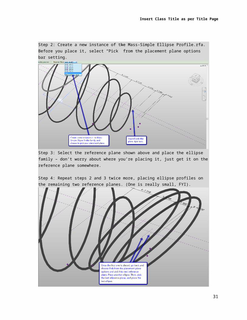
Step 2: Create a new instance of the Mass-Simple Ellipse Profile.rfa. Before you place it, select “Pick” from the placement plane options bar setting.
Step 3: Select the reference plane shown above and place the ellipse family – don’t worry about where you’re placing it, just get it on the reference plane somewhere.
Step 4: Repeat steps 2 and 3 twice more, placing ellipse profiles on the remaining two reference planes. (One is really small, FYI).
22

Insert Class Title as per Title Page
Step 5: Go to your North Elevation view and align your three new ellipses left or right so they are centered on the center reference plane.
Step 6: Select the profile family shown below (you’ll have to tab-select to get it most likely).
Step 7: Map the parameters of this ellipse, and the next two as shown above. (P01 is the front of the plane, P02 is next, P03 is next, etc…)
- mA = P0X VA- MA = P0X HA
23

Insert Class Title as per Title Page
Step 8: Go back to your North Elevation and move your three ellipse profiles to match up with the guide points placed in the family for you.
Now we’re ready to make a form!
Step 9: Start with the front of the plane and tab-select to get the first profile family selected. Then, hover over the second profile, tab to get to the family, and then control-select to add it to the selection.
There is a bug that popped up in WU2 I believe that causes a fatal error if you accidentally grab a shape handle of the profile after having one or more of the families selected.
24

Insert Class Title as per Title Page
Step 10: Once you have all the profiles selected, just hit Create Form to create the form.
Step 10: Once you have your form, you can map it to the correct material parameter.
Step 11: As with any family, flex it to make sure (and see how) it works. You can easily adjust the shape of the fuselage through the mapped parameters in the Family Types dialog.
25

Insert Class Title as per Title Page
Hosting a Profile Rig onto a Placement Rig to make formsCreating a form from profiles hosted onto a placement rig is no different, except that you have made it much easier to rotate or move those profiles around after the form is made.
Exercise 5: Modifying created forms to get “impossible” resultsWe will use some profiles to create a form, and then modify the placement of the profile to get the form we really want.
Step 1: To get started, open “E5.1-Engine Start.rfa”.
Step 2: Select the three profiles in the order below and hit Create Form.
Step 3: You’ll end up with something like this, which doesn’t actually look like an engine.
If you’re wondering why we’re doing this, Revit picks the order of the profiles in a loft when you hit create form (regardless of pick order) and you cannot re-order the profiles. So, if you want to create geometry like this you have to create the form so that the profiles are ordered as intended automatically and then move the profiles into their correct position.
26

Insert Class Title as per Title Page
Step 4: Zoom out and select the reference plane shown below. Click in the dimension label next to the engine and change the value to 0.
Step 5: You can see the engine now looks correct. You can now map this to the “Engine” material parameter.
In this case, the geometry was so simple that no rigs were really justified. However, this technique works very well with both geometry rigs and placement rigs.
27
Insert Class Title as per Title Page
Hosting a Profile Rig into a Placement Rig to make formsSome placement rigs like line based or adaptive component rigs allow you to use a vector during the placement. This can be particularly interesting if you can use that vector to control a geometry rig that is being placed by the placement rig. This can allow you to create a scalar relationship or control the direction a profile is oriented towards to get interesting results.
Using Masses in the Project EnvironmentOnce your mass is made, you’re really getting to the meat and potatoes of how it can impact your project. Now, all this lead up may seem like a lot of work; but if you use one of your masses in a real project you’ll quickly discover why parametric driven change is far better than manual editing of masses. The images below are an example of what happens in both scenarios.
Clearly, non-destructive edits of masses are critical when you’ve based tens or even hundreds of man hours in the project on the masses you’ve created. This is particularly true for curtain systems as you can make a lot of instance driven customizations that get lost when you have to select a new face instead of just updating to the existing one. Of course, since you’ve got a cool mass you’ll want to use it for as many things as you possibly can in the project environment:
Mass Floors and Mass SchedulesIf you’ve got a solid mass you can do some quick programming level calculations using the masses you’ve created. Worried about floor area ratios? Maximum allowable areas? Using rough area to approximate occupancy? Mass floors and mass schedules are your new best friend.
Exercise 6: Applying mass floors to a mass and scheduling themFor this example we will load our completed 747 into a project and apply the levels in that project to the mass; then we’ll create a schedule and look at the results to see whether we’re getting enough area per passenger…
Step 1: To get started, open “E6.1-Project747 Start.rfa” and select the Fuselage Simple mass.
28
Insert Class Title as per Title Page
Step 2: With the fuselage simple mass selected, click on the Mass Floors edit button in the properties palette. Check the boxes for Level 2 and Level 3.
Step 3: You’ll notice that the values in the properties for floor area are now updated with a value, which might be something we want to create some schedules for.
Step 4: To create a Mass schedule or a Mass Floor schedule, go to the View tab and hit Schedules. When you scroll down the categories you’ll see Mass and subcategories of Masses are exposed to the scheduling tool. We already have schedules in the project, so hit cancel.
29

Insert Class Title as per Title Page
Step 5: Open the Mass Schedule and Mass Floor Schedule from the Project Browser.
Step 6:Select the fuselage simple mass and edit the type properties to change the shape of the mass. You’ll see the values in the schedules update. This is particularly powerful for programming and other conceptual level area analyses.
30
Insert Class Title as per Title Page
Energy AnalysisLikewise, if you have a solid mass you can do energy analysis of that mass using green building studio. While green building studio may not be the most accurate energy analysis tool in the world, none of the ones out there currently are going to be even close to hitting a bull’s eye. All of the building analysis tools are best used by creating a baseline and then running several alternatives and seeing what the delta (difference) is between those experiments. Having a parametric mass just makes creating all those alternatives so much easier.
Face Based Building ComponentsRegardless if your mass is a surface or a solid, the classic use case for massing in Revit is as a host for face-based system families. Need a warped wall, sloped elliptical curtain systems, a multi-curved roof, or a skateboard park floor – look no farther, this is what you’ve been looking for.
Exercise 7: Applying building components to a mass surfaceWe will create some building elements using our 747 as a surface on which to place face-based system families like walls and curtainwalls. Then, we’ll make some parametric changes to the 747 and update those elements to demonstrate why foolproof parametric masses really are the best workflow for using masses to create and control real project outcomes.
Step 1: To get started, open “E6.1-Project747 Scheduled.rfa” and select the Fuselage Simple mass. Use the temporary isolate command to hide the other complex mass.
Step 2: Go to the Architecture tab and hit the “Curtain System” tool.
31
Insert Class Title as per Title Page
Step 3: Select both the top and bottom surfaces of the mass, and then hit “Create System”.
Step 4: We can also create floors on the mass floor faces. Hit the drop down below the floor tool, and pick Floor by Face, then select the mass floors and create floors.
32

Insert Class Title as per Title Page
Step 5: If you turn off the Show Mass mode, you’ll notice we don’t have something very pretty. Select the curtainwall and edit its properties to panelize the surface much more than it is by default.
Step 6: Much better. Go ahead and add some instance level changes to the curtain system too. Add curtain grids to better match the form, remove segments, change individual mullions, etc…
33
Insert Class Title as per Title Page
Step 7: Now, turn the show mass mode back on, select the fuselage mass, and change its type properties again.
Step 8: Once you have something you like, select the curtainwall and hit “Update to Face” from the ribbon. You can do the same thing for the floors as well.
Step 9: Turn off the Show Mass mode again and you’re done.
34