lecture 09-12
TRANSCRIPT

ME 101: Engineering Mechanics
Rajib Kumar Bhattacharjya
Department of Civil Engineering
Indian Institute of Technology Guwahati
M Block : Room No 005 : Tel: 2428
www.iitg.ernet.in/rkbc

Q. No. 1 For the trusses shown below, indicate the members, which
carry zero force.

Q. No. 2 For the plane truss shown in figure below, find out the forces in
members in FE, FC, and BC by considering all members as pin connected using
method of sections.

Q. No. 3 The two forces acting on the handles of the pipe wrenches
constitute a couple M. Express the couple as a vector.

Q. No. 4 The beam is subjected to uniformly distributed moment m
(moment/length) and is shown in Figure 2. Draw the shear force and bending
moment diagrams for the beam.
L
A B
m

Solution of Q. No. 1
115

Consider the Right Segment:
Solution of Q. No. 2

NmijC
kjiFrC
jir
jijr
jirjr
BA
BA
BA
BA
)ˆ75ˆ5.22(
ˆ150)ˆ5.0ˆ15.0(
ˆ5.0ˆ15.0
ˆ25.0ˆ15.0ˆ25.0
ˆ25.0ˆ15.0,ˆ25.0
−=⇒
×−−=×=
−−=⇒
−−−=
+=−=
r
rrr
r
r
rr
Taking O as origin
Solution of Q. No. 3

L
m
ByAy
Ax
BMD
SFD
-m
∑Fx = 0 � Ax = 0
∑MA = 0 � mL - ByL = 0
By = m
∑MB = 0� mL+ AyL = 0
Ay = - m
Shear force at any section = - m
Bending moment at a distance x
from A:
Mx = Ay x + m x
Since Ay = - m � Mx = 0
Bending moment at any section = 0
Solution of Q. No. 4

Friction

Friction
Usual Assumption till now:
Forces of action and reaction between contacting surfaces act normal to the surface
�valid for interaction between smooth surfaces
�in many cases ability of contacting surfaces to support tangential forces is very important (Ex: Figure above)
Frictional Forces
Tangential forces generated between contacting surfaces
• occur in the interaction between all real surfaces
• always act in a direction opposite to the direction of motion
FrictionFrictionFrictionFriction
Frictional forces are Not Desired in some cases:
• Bearings, power screws, gears, flow of fluids in pipes, propulsion of aircraft and missiles through the atmosphere, etc.
• Friction often results in a loss of energy, which is dissipated in the form of heat
• Friction causes Wear
Frictional forces are Desired in some cases:
• Brakes, clutches, belt drives, wedges
• walking depends on friction between the shoe and the ground
Ideal Machine/Process: Friction small enough to be neglected
Real Machine/Process: Friction must be taken into account
Types of Friction
Dry Friction (Coulomb Friction)
occurs between unlubricated surfaces of two solids
Effects of dry friction acting on exterior surfaces of rigid bodies � ME101
Fluid Friction
occurs when adjacent layers in a fluid (liquid or gas) move at a different velocities. Fluid friction also depends on viscosity of the fluid. � Fluid Mechanics
Internal Friction
occurs in all solid materials subjected to cyclic loading, especially in those materials, which have low limits of elasticity � Material Science

• Block of weight W placed on horizontal surface.
Forces acting on block are its weight and reaction of surface N.
• Small horizontal force P applied to block. For
block to remain stationary, in equilibrium, a horizontal component F of the surface reaction
is required. F is a Static-Friction force.
• As P increases, static-friction force F increases
as well until it reaches a maximum value Fm.
NF sm µ=
• Further increase in P causes the block to begin
to move as F drops to a smaller Kinetic-Friction force Fk.
NF kk µ=
Mechanism of Dry Friction
R
Φ
StaticEquilibrium Motion
µs is the Coefficient of Static Frictionµk is the Coefficient of Kinetic Friction

• Maximum static-friction force:
NF sm µ=
• Kinetic-friction force:
sk
kk NF
µµ
µ
75.0≅
=
• Maximum static-friction force and kinetic-friction force are:
- proportional to normal force
- dependent on type and condition of contact surfaces
- independent of contact area
Mechanism of Dry Friction
When the surfaces are in relative motion, the contacts are more nearly along the tops of the humps, and the t-components of
the R’s are smaller than when the surfaces are at rest relative to one another
� Force necessary to maintain motion is generally less than that required to start the block when the surface irregularities are more nearly in mesh � F
m> F
k
A friction coefficient reflects roughness,
which is a geometric property of surfaces
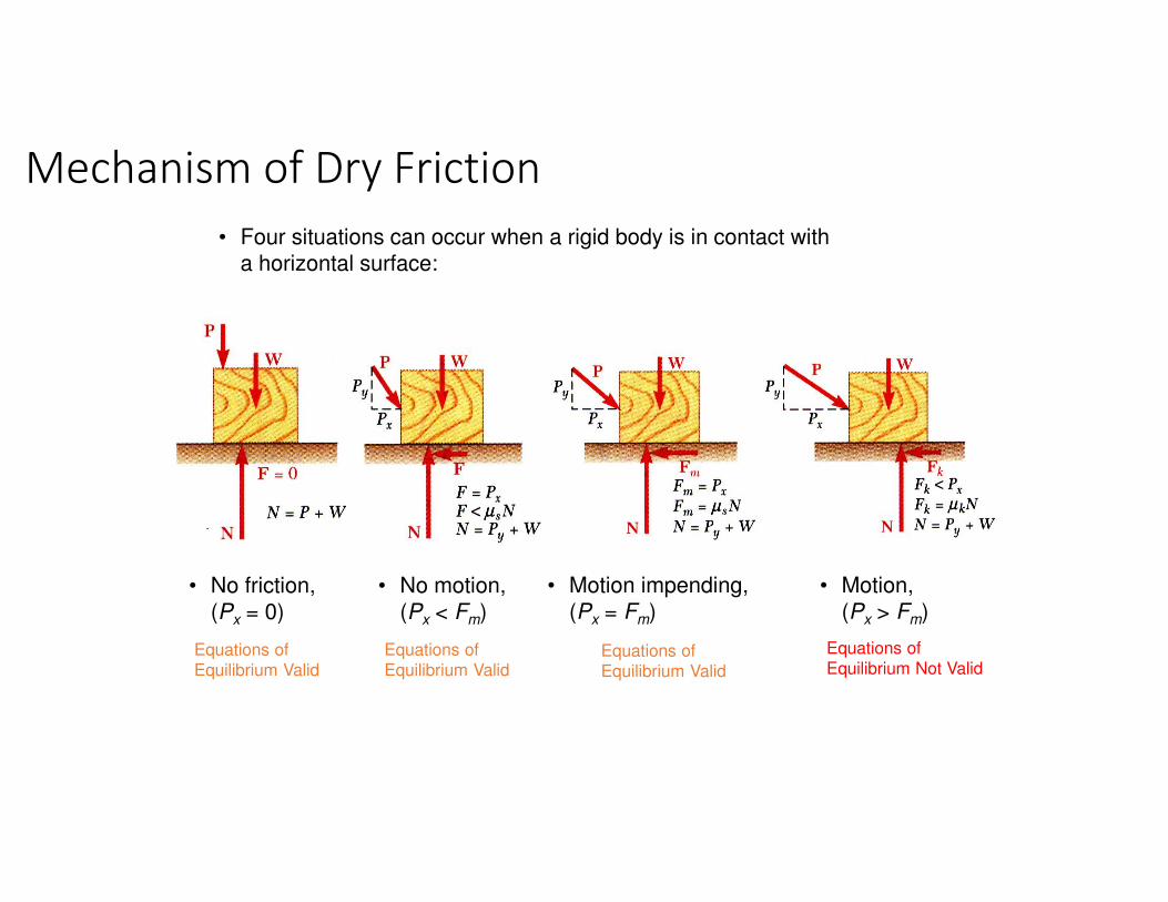
• Four situations can occur when a rigid body is in contact with
a horizontal surface:
Mechanism of Dry Friction
• No friction,
(Px = 0)
Equations of Equilibrium Valid
• No motion,
(Px < Fm)
Equations of Equilibrium Valid
• Motion impending,
(Px = Fm)
Equations of Equilibrium Valid
• Motion,
(Px > Fm)
Equations of Equilibrium Not Valid

Sometimes convenient to replace normal force N & friction force F by their resultant R:
• No friction • No motion • Motion impending
ss
sms
N
N
N
F
µφ
µφ
=
==
tan
tan
• Motion
kk
kkk
N
N
N
F
µφ
µφ
=
==
tan
tan
Mechanism of Dry Friction
Friction Angles
= angle of static friction, = angle of kinetic frictionsφ kφvertex angle

• Consider block of weight W resting on board with
variable inclination angle θ.
• No friction • No motion • Motion impending
Angle of Repose =
Angle of Static Friction
• Motion
The reaction R is
not vertical
anymore, and the
forces acting on
the block are
unbalanced
Mechanism of Dry Friction

Dry FrictionExample
Determine the maximum angle Ө
before the block begins to slip.
µs = Coefficient of static friction between
the block and the inclined surface
Solution: Draw the FBD of the block
Max angle occurs when F = Fmax
= µs N
Therefore, for impending motion:
The maximum value of Ө is known as Angle of Repose
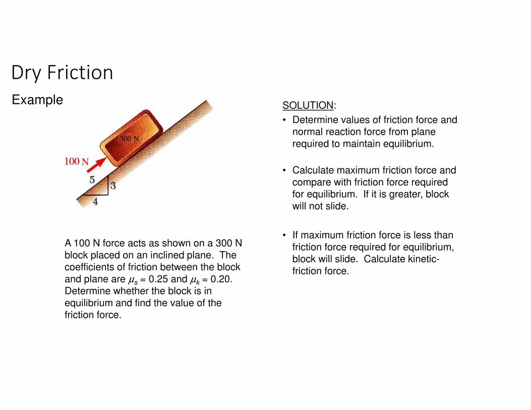
A 100 N force acts as shown on a 300 N
block placed on an inclined plane. The coefficients of friction between the block
and plane are µs = 0.25 and µk = 0.20. Determine whether the block is in
equilibrium and find the value of the friction force.
SOLUTION:
• Determine values of friction force and normal reaction force from plane
required to maintain equilibrium.
• Calculate maximum friction force and
compare with friction force required for equilibrium. If it is greater, block
will not slide.
• If maximum friction force is less than
friction force required for equilibrium, block will slide. Calculate kinetic-
friction force.
Dry Friction
Example

SOLUTION:
• Determine values of friction force and normal reaction force from plane required to maintain
equilibrium.
:0=∑ xF ( ) 0N 300 - N 10053 =− F
N 80−=F
:0=∑ yF ( ) 0N 300 - 54 =N
N 240=N
• Calculate maximum friction force and compare with
friction force required for equilibrium. If it is greater, block will not slide.
( ) N 60N 24025.0 === msm FNF µ
The block will slide down the plane along F.
Dry Friction
� F acting upwards

• If maximum friction force is less than friction force
required for equilibrium, block will slide. Calculate kinetic-friction force.
( )N 240200
N
.
FF kkactual
=
== µ
N 48=actualF
Dry Friction

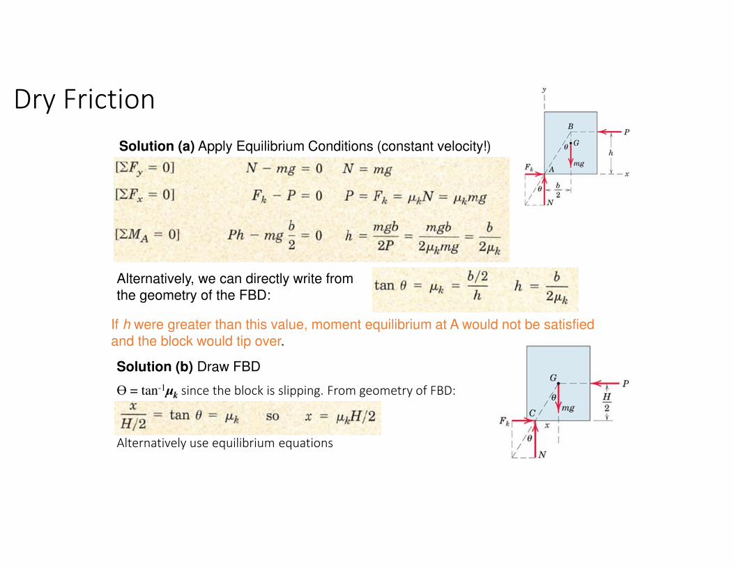
CASE I
CASE II

The block moves with constant velocity under the action of P. µk is the Coefficient
of Kinetic Friction. Determine:
(a) Maximum value of h such that the
block slides without tipping over
(b) Location of a point C on the bottom
face of the block through which resultant of the friction and normal
forces must pass if h=H/2
Solution: (a) FBD for the block on the
verge of tipping:
The resultant of Fk and N passes through
point B through which P must also pass,
since three coplanar forces in equilibrium
are concurrent.
Friction Force:
Fk
= µk
N since slipping occurs
Ө = tan-1µk
Dry Friction
Example
Alternatively, we can directly write from
the geometry of the FBD:
Dry Friction
Solution (a) Apply Equilibrium Conditions (constant velocity!)
If h were greater than this value, moment equilibrium at A would not be satisfied
and the block would tip over.
Solution (b) Draw FBD
Ө = tan-1µk
since the block is slipping. From geometry of FBD:
Alternatively use equilibrium equations

Applications of Friction in Machines
Wedges
Coefficient of Friction for each pair of
surfaces µ = tanϕ (Static/Kinetic)
FBDs:
Reactions are inclined at an angle Φfrom their respective normals and are
in the direction opposite to the motion.
Force vectors acting on each body can also
be shown.
Forces to raise load
R2 is first found from upper diagram since
mg is known.
Then P can be found out from the lower diagram
since R2 is known.
• Simple machines used to raise heavy loads.
• Force required to lift block is significantly less than block weight.
• Friction prevents wedge from sliding out.• Want to find minimum force P to raise block.
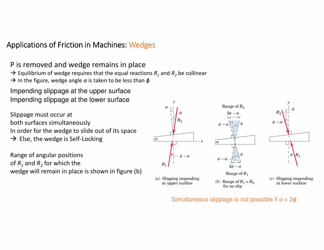
Applications of Friction in Machines: Applications of Friction in Machines: Applications of Friction in Machines: Applications of Friction in Machines: WedgesWedgesWedgesWedges
P is removed and wedge remains in place� Equilibrium of wedge requires that the equal reactions R1 and R2 be collinear
� In the figure, wedge angle α is taken to be less than ϕ
Impending slippage at the upper surface
Impending slippage at the lower surface
Slippage must occur at
both surfaces simultaneously
In order for the wedge to slide out of its space
� Else, the wedge is Self-Locking
Range of angular positions
of R1 and R2 for which the
wedge will remain in place is shown in figure (b)
Simultaneous slippage is not possible if α < 2ϕ

Applications of Friction in Machines: Wedges
A pull P is required on the wedge for withdrawal of the wedge� The reactions R
1and R
2must act on the opposite sides of their normal from those when
the wedge was inserted
� Solution by drawing FBDs and vector polygons
� Graphical solution
� Algebraic solutions from trigonometry
Forces to raise load Forces to lower load

Applications of Friction in Machines
Example: WedgeCoefficient of Static Friction for both pairs of wedge = 0.3Coefficient of Static Friction between block and horizontal surface = 0.6Find the least P required to move the block
Solution: Draw FBDs
µs = 0.60
µs = 0.30
-R2 since we are showing vectors

Applications of Friction in Machines
Solution: W = 500x9.81 = 4905 N
Three ways to solve
Method 1:
Equilibrium of FBD of the Block∑FX = 0
R2 cos ϕ1 = R3 sin ϕ2 � R2 = 0.538R3
∑FY = 0
4905 + R2 sin ϕ1 = R3 cos ϕ2 � R3 = 6970 N� R2 = 3750 N
Equilibrium of FBD of the Wedge
∑FX = 0 R2 cos ϕ1 = R1 cos(ϕ1+5) � R1 = 3871 N
∑FY = 0 R1 sin(ϕ1+5) + R2 sin ϕ1 = P
� P = 2500 N
X
Y

Applications of Friction in Machines
Solution:
Method 2:Using Equilibrium equations along reference axes a-a and b-b
� No need to solve simultaneous equationsAngle between R2 and a-a axis = 16.70+31.0 = 47.7o
Equilibrium of Block:
Equilibrium of Wedge:Angle between R2 and b-b axis = 90-(2Φ1+5) = 51.6o
Angle between P and b-b axis = Φ1+5 = 21.7o

Applications of Friction in Machines
Solution:
Method 3:Graphical solution using vector polygons
Starting with equilibrium of the block:
W is known, and directions of R2 and R3
are known
� Magnitudes of R2 and R3 can be determined graphically
Similarly, construct vector polygon for the
wedge from known magnitude of R2, and known directions of R2 , R1, and P.
� Find out the magnitude of P graphically

Applications of Friction in Machines
Square Threaded Screws• Used for fastening and for transmitting power or motion
• Square threads are more efficient• Friction developed in the threads largely determines
the action of the screw
FBD of the Screw: R exerted by the thread of the jack frame
on a small portion of the screw thread is shown
Lead = L = advancement per revolutionL = Pitch – for single threaded screw
L = 2xPitch – for double threaded screw (twice advancement per revolution)
Pitch = axial distance between adjacent threads on a helix or screw
Mean Radius = r ; α = Helix Angle
Similar reactions exist on all segments of the screw threads
Analysis similar to block on inclined plane since friction force does not depend on area of contact.
• Thread of base can be “unwrapped” and shown as
straight line. Slope is 2πr horizontally and lead L vertically.

Applications of Friction in Machines: Screws
If M is just sufficient to turn the screw � Motion ImpendingAngle of friction = ϕ (made by R with the axis normal to the thread)
� tan ϕ = µ
Moment of R @ vertical axis of screw = Rsin(α+ϕ)r� Total moment due to all reactions on the thread = ∑Rsin(α+ϕ)r� Moment Equilibrium Equation for the screw:
�M = [r sin(α + ϕ)] ∑R
Equilibrium of forces in the axial direction: W = ∑R cos(α + ϕ) �W = [cos(α + ϕ)] ∑R
Finally � M = W r tan(α + ϕ)
Helix angle α can be determined by unwrapping the thread of the screw for one complete turn
α = tan-1 (L/2πr)
Applications of Friction in Machines: Screws
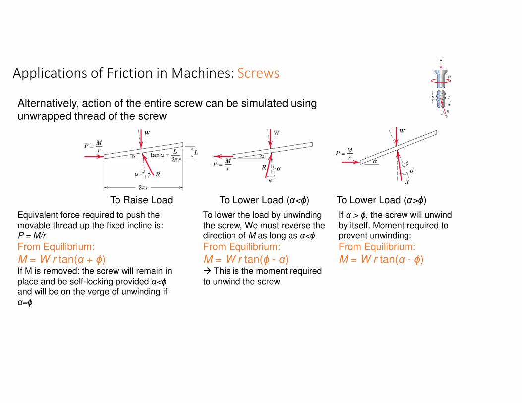
Alternatively, action of the entire screw can be simulated using unwrapped thread of the screw
Equivalent force required to push the
movable thread up the fixed incline is:
P = M/r
From Equilibrium:
M = W r tan(α + ϕ)If M is removed: the screw will remain in
place and be self-locking provided α<ϕ
and will be on the verge of unwinding if
α=ϕ
To Raise Load
To lower the load by unwinding
the screw, We must reverse the
direction of M as long as α<ϕ
From Equilibrium:
M = W r tan(ϕ - α)� This is the moment required
to unwind the screw
To Lower Load (α<ϕ)
If α > ϕ, the screw will unwind
by itself. Moment required to
prevent unwinding:
From Equilibrium:
M = W r tan(α - ϕ)
To Lower Load (α>ϕ)

Sample Problem 8.5
8 - 36
A clamp is used to hold two pieces of
wood together as shown. The clamp
has a double square thread of mean
diameter equal to 10 mm with a pitch
of 2 mm. The coefficient of friction
between threads is µs = 0.30.
If a maximum torque of 40 N*m is
applied in tightening the clamp,
determine (a) the force exerted on the
pieces of wood, and (b) the torque
required to loosen the clamp.
SOLUTION
• Calculate lead angle and pitch angle.
• Using block and plane analogy with
impending motion up the plane, calculate
the clamping force with a force triangle.
• With impending motion down the plane,
calculate the force and torque required to
loosen the clamp.

Sample Problem 8.5SOLUTION
• Calculate lead angle and pitch angle. For the double
threaded screw, the lead L is equal to twice the pitch.
( )
30.0tan
1273.0mm 10
mm22
2tan
==
===
ss
r
L
µφ
ππθ °= 3.7θ
°= 7.16sφ
kN97.17=W
M = W r tan(α + ϕ)
40 = W �
����tan(7.3+16.7)

Sample Problem 8.5• With impending motion down the plane, calculate
the force and torque required to loosen the clamp.
mN87.14 ⋅=Torque
M = W r tan(ϕ - α)
M =17.97x1000 �
����tan(16.7-7.3)

Applications of Friction in Machines
Example: ScrewSingle threaded screw of the vise has a mean diameter of 25 mm and a lead of 5 mm. A 300 N pull applied
normal to the handle at A produces a clamping force of 5 kN between the jaws of the vise. Determine:
(a) Frictional moment MB developed at B due to thrust of the screw against body of the jaw
(b) Force Q applied normal to the handle at A required to loosen the vise
µs in the threads = 0.20
∑MC =0
� T = 8 kN
Solution: Draw FBD of the jaw to find
tension in the screw
Find the helix angle α and the friction angle ϕ
α = tan-1 (L/2πr) = 3.64o
tan ϕ = µ� ϕ = 11.31o

Applications of Friction in Machines
Example: ScrewSolution:(a) To tighten the vise
Draw FBD of the screw
M = T r tan(α + ϕ)
60-MB = 8000(0.0125)tan(3.64+11.31)MB = 33.3 Nm
(a) To loosen the vise (on the verge of being loosened)
Draw FBD of the screw: Net moment = applied moment M’ minus MB
M = T r tan(ϕ - α)
M’ - 33.3= 8000(0.0125)tan(11.31-3.64)M’ = 46.8 Nm
Q = M’/d = 46.8/0.2 = 234 N

Dry Friction
The moveable bracket shown may be
placed at any height on the 3-cm diameter pipe. If the coefficient of
friction between the pipe and bracket is 0.25, determine the minimum distance
x at which the load can be supported. Neglect the weight of the bracket.
SOLUTION:
• When W is placed at minimum x, the
bracket is about to slip and friction
forces in upper and lower collars are at
maximum value.
• Apply conditions for static equilibrium
to find minimum x.
Example

Dry Friction
SOLUTION:
• When W is placed at minimum x, the bracket is about to
slip and friction forces in upper and lower collars are at
maximum value.
BBsB
AAsA
NNF
NNF
25.0
25.0
==
==
µ
µ
• Apply conditions for static equilibrium to find minimum x.
:0=∑ xF 0=− AB NN AB NN =
:0=∑ yF
WN
WNN
WFF
A
BA
BA
=
=−+
=−+
5.0
025.025.0
0
WNN BA 2==
:0=∑ BM ( ) ( ) ( )
( ) ( )
( ) ( ) ( ) 05.1275.026
05.125.036
0cm5.1cm3cm6
=−−−
=−−−
=−−−
xWWW
xWNN
xWFN
AA
AA
cm12=x

Applications of Friction in Machines
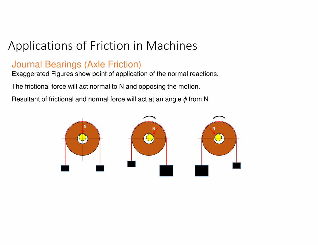
Journal Bearings (Axle Friction)
• Journal bearings provide lateral support to rotating shafts.
• Lateral load acting on the shaft is L.
• Thrust bearings provide axial support to rotating shafts.
• Frictional resistance of fully lubricated bearings depends on clearances, speed and lubricant viscosity.
• Partially lubricated axles and bearings can be assumed to be in direct contact along a straight line
Circle of radius rf is
called Friction Circle
Applications of Friction in Machines
Journal Bearings (Axle Friction)Exaggerated Figures show point of application of the normal reactions.
The frictional force will act normal to N and opposing the motion.
Resultant of frictional and normal force will act at an angle ϕ from N
NN N

Applications of Friction in Machines
Journal Bearings (Axle Friction)
Consider a dry or partially lubricated Journal Bearing
- with contact with near contact betn shaft and bearing
- As the shaft begins to turn in the direction shown,
it will roll up the inner surface of bearing until it slips at A
- Shaft will remain in a more or less fixed position during rotation
- Torque M required to maintain rotation, and the radial load L on the shaft will cause reaction R
at the contact point A.
- For vertical equilibrium, R must be equal to L but will not be collinear
- R will be tangent to a small circle of radius rf called the friction circle
∑MA =0 � M = Lrf = Lr sin ϕ
For a small coefficient of friction, ϕ is small � sinϕ ≈ tanϕ
� M = µ Lr (since µ= tanϕ) � Use equilibrium equations to solve a problem
� Moment that must be applied to the shaft to overcome friction for a dry or partially lubricated
journal bearing

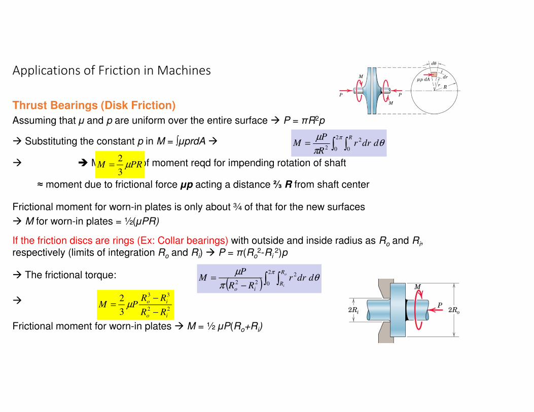
Thrust Bearings (Disk Friction)• Thrust bearings provide axial support to rotating shafts.
• Axial load acting on the shaft is P.
• Friction between circular surfaces under distributed normal pressure (Ex: clutch plates, disc brakes)
Consider two flat circular discs whose shafts are mounted in bearings: they can be brought under contact under P
Max torque that the clutch can transmit =
M required to slip one disc against the other
p is the normal pressure at any location between the plates
� Frictional force acting on an elemental area = µpdA; dA = r dr dӨ
Moment of this elemental frictional forceabout the shaft axis = µprdA
Total M = ∫µprdA over the area of disc
Applications of Friction in Machines
End/Pivot Bearing Collar Bearing
Sanding Machine
Thrust Bearings (Disk Friction)
Assuming that µ and p are uniform over the entire surface � P = πR2p
� Substituting the constant p in M = ∫µprdA �
� � Magnitude of moment reqd for impending rotation of shaft
≈ moment due to frictional force µp acting a distance ⅔ R from shaft center
Frictional moment for worn-in plates is only about ¾ of that for the new surfaces
� M for worn-in plates = ½(µPR)
If the friction discs are rings (Ex: Collar bearings) with outside and inside radius as Ro and Ri, respectively (limits of integration Ro and Ri) � P = π(Ro
2-Ri 2)p
� The frictional torque:
�
Frictional moment for worn-in plates � M = ½ µP(Ro+Ri)
Applications of Friction in Machines
∫ ∫=π
θπ
µ 2
0 0
2
2
R
ddrrR
PM
22
33
3
2
io
io
RR
RRPM
−
−= µ
( ) ∫ ∫−
=π
θπ
µ 2
0
2
22
o
i
R
Rio
ddrrRR
PM
PRM µ3
2=
Applications of Friction in Machines
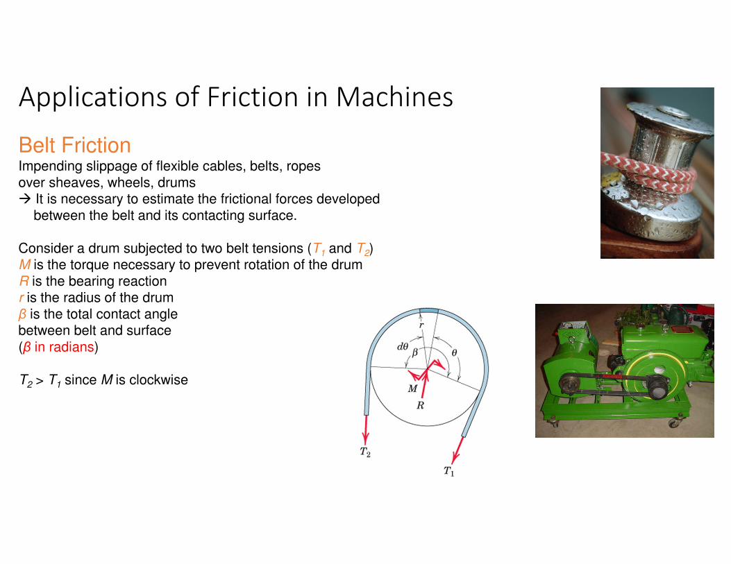
Belt FrictionImpending slippage of flexible cables, belts, ropes
over sheaves, wheels, drums� It is necessary to estimate the frictional forces developed
between the belt and its contacting surface.
Consider a drum subjected to two belt tensions (T1 and T2)M is the torque necessary to prevent rotation of the drum
R is the bearing reactionr is the radius of the drum
β is the total contact angle between belt and surface
(β in radians)
T2 > T1 since M is clockwise
Applications of Friction in Machines
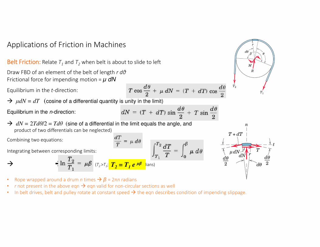
Belt Friction: Belt Friction: Belt Friction: Belt Friction: Relate T1 and T2 when belt is about to slide to left
Draw FBD of an element of the belt of length r dθ
Frictional force for impending motion = µ dN
Equilibrium in the t-direction:
� µdN = dT (cosine of a differential quantity is unity in the limit)
Equilibrium in the n-direction:
� dN = 2Tdθ/2 = Tdθ (sine of a differential in the limit equals the angle, and
product of two differentials can be neglected)
Combining two equations:
Integrating between corresponding limits:
� � (T2 >T1; e = 2.718…; β in radians)
• Rope wrapped around a drum n times � β = 2πn radians
• r not present in the above eqn � eqn valid for non-circular sections as well
• In belt drives, belt and pulley rotate at constant speed � the eqn describes condition of impending slippage.
T2
= T1
e µβ

Applications of Friction in Machines
Wheel Friction or Rolling ResistanceResistance of a wheel to roll over a surface is caused by deformation between two
materials of contact.� This resistance is not due to tangential frictional forces
� Entirely different phenomenon from that of dry friction
If a rigid cylinder rolls at constant velocity along a rigid surface,the normal force exerted by the surface on the cylinder acts at
the tangent point of contact � No Rolling Resistance
Steel is very stiff
� Low Rolling ResistanceSignificant Rolling Resistance
between rubber tyre and tar road
Large Rolling Resistance
due to wet field
Rigid
Rigid

Applications of Friction in Machines
Wheel Friction or Rolling ResistanceActually materials are not rigid � deformation occurs
� reaction of surface on the cylinder consists of a distribution of normal pressure.
Consider a wheel under action of a load W on axle
and a force P applied at its center to produce rolling� Deformation of wheel and supporting surface
� Resultant R of the distribution of normal pressure must pass through wheel center for the wheel to be in equilibrium (i.e., rolling at a constant speed)
� R acts at point A on right of wheel center for rightwards motion
Force P reqd to maintain rolling at constant speed can be appx estimated as:
∑MA = 0 � Wa = Prcosθ (cosθ ≈ 1 � deformations are very small compared to r)
� µr is called the Coefficient of Rolling Resistance
• µr is the ratio of resisting force to the normal force � analogous to µs or µk
• No slippage or impending slippage in interpretation of µr
θW
WWr
aP rµ==

Applications of Friction in Machines
Examples: Journal BearingsTwo flywheels (each of mass 40 kg and diameter 40 mm) are mounted on a shaft, which is
supported by a journal bearing. M = 3 Nm couple is reqd on the shaft to maintain rotation of the flywheels and shaft at a constant low speed.
Determine: (a) coeff of friction in the bearing, and (b) radius rf of the friction circle.
Solution: Draw the FBD of the shaft and the bearing
(a) Moment equilibrium at O
M = Rrf = Rrsinϕ M = 3 Nm, R = 2x40x9.81 = 784.8 N, r = 0.020 m
� sinϕ = 0.1911 � ϕ = 11.02o
(b) rf = rsinϕ = 3.82 mm

Applications of Friction in Machines
Examples: Disk FrictionCircular disk A (225 mm dia) is placed on top of disk B (300 mm dia) and is subjected to a
compressive force of 400 N. Pressure under each disk is constant over its surface. Coeff of friction betn A and B = 0.4. Determine:
(a) the couple M which will cause A to slip on B. (b) Min coeff of friction µ between B and supporting
surface C which will prevent B from rotating.
Solution:
(a) Impending slip between A and B:
µ=0.4, P=400 N, R=225/2 mmM = 2/3 x 0.4 x 400 x 0.225/2 � M = 12 Nm
(b) Impending slip between B and C :
Slip between A and B � M = 12 Nm
µ=? P=400 N, R=300/2 mm12 = 2/3 x µ x 400 x 0.300/2 � µ = 0.3
PRM µ3
2=

Applications of Friction in Machines
Examples: Belt FrictionA force P is reqd to be applied on a flexible cable that
supports 100 kg load using a fixed circular drum. µ between cable and drum = 0.3
(a) For α = 0, determine the max and min P in ordernot to raise or lower the load
(b) For P = 500 N, find the min α before the load begins to slip
Solution: Impending slippage of the cable over the fixed drum is given by: T
2= T
1e µβ
Draw the FBD for each case
(a) µ = 0.3, α = 0, β = π/2 radFor impending upward motion of the load: T
2= Pmax; T1
= 981 N
Pmax/981 = e0.3(π/2) � Pmax = 1572 NFor impending downward motion: T
2= 981 N; T
1= Pmin
981/Pmin = e0.3(π/2) � Pmin = 612 N
(b) µ = 0.3, α = ?, β = π/2+α rad, T2
= 981 N; T1
= 500 N
981/500 = e0.3β � 0.3β = ln(981/500) � β = 2.25 rad� β = 2.25x(360/2π) = 128.7o
� α = 128.7 - 90 = 38.7o

Applications of Friction in Machines
Examples: Rolling ResistanceA 10 kg steel wheel (radius = 100 mm) rests on an inclined
plane made of wood. At θ=1.2o, the wheel begins to roll-downthe incline with constant velocity.
Determine the coefficient of rolling resistance.
Solution: When the wheel has impending motion, the
normal reaction N acts at point A defined by the dimension a.Draw the FBD for the wheel:
r = 100 mm, 10 kg = 98.1 N
Alternatively, ∑MA = 0
� 98.1(sin1.2)(r appx) = 98.1(cos1.2)a(since rcos1.2 = rx0.9998 ≈ r)
� a/r = µr = 0.0209
WWr
aP rµ==Using simplified equation directly:
Here P = 98.1(sin1.2) = 2.05 NW = 98.1(cos1.2) = 98.08 N
� Coeff of Rolling Resistance µr = 0.0209