lecture 13 hydraulic fracturing for unconventional resources
TRANSCRIPT
Lecture 13
Hydraulic Fracturing for Unconventional Resources
비전통 자원개발을 위한 수압파쇄
Ki-Bok Min, PhD
Professor
Department of Energy Resources Engineering
Seoul National University
Reservoir Geomechanics, Fall, 2020
Disclaimer
• All the figures in the slides are taken from “Zoback MD, KohliAH, 2019, Unconventional Geomechanics, Cambridge Univpress” & “Zoback MD, 2007, Reservoir Geomechanics, Cambridge Univ press” unless otherwise stated.
• Materials in these slides cannot be used without the written consent from the instructor
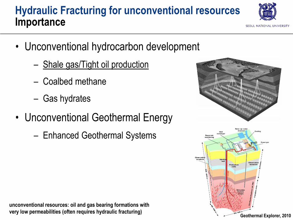
Hydraulic Fracturing for unconventional resourcesImportance
• Unconventional hydrocarbon development
– Shale gas/Tight oil production
– Coalbed methane
– Gas hydrates
• Unconventional Geothermal Energy
– Enhanced Geothermal Systems
Geothermal Explorer, 2010
unconventional resources: oil and gas bearing formations with
very low permeabilities (often requires hydraulic fracturing)
Hydraulic Fracturing for unconventional resourcesTopic
• Introduction to unconventional geomechanics
– Development of Unconventional oil and gas
– Permeability
– Horizontal Drilling and Multi-Stage Hydraulic Fracturing
• Horizontal Drilling and Multi-Stage Hydraulic Fracturing
– Hydraulic fracturing
confinement
Initiation and propagation
Models of hydraulic fracturing – PKN, KGD and radial models
Effect of leakoff
Stress shadow effect
SNU Geomechanics Toolbox
– Induced shear slip during hydraulic fracturing
• Deep Geothermal Energy (Enhanced Geothermal Systems)

Energy MixClimate Change - Paris Agreement
• The Paris Agreement (파리협약, 12 Dec 2015)
– 195 countries agreed
– …. pursuing efforts to limit the temperature increase to 1.5 °C above pre-industrial levels.
– Check the target every five years.
– Prepare 100 billion USD/year for developing countries
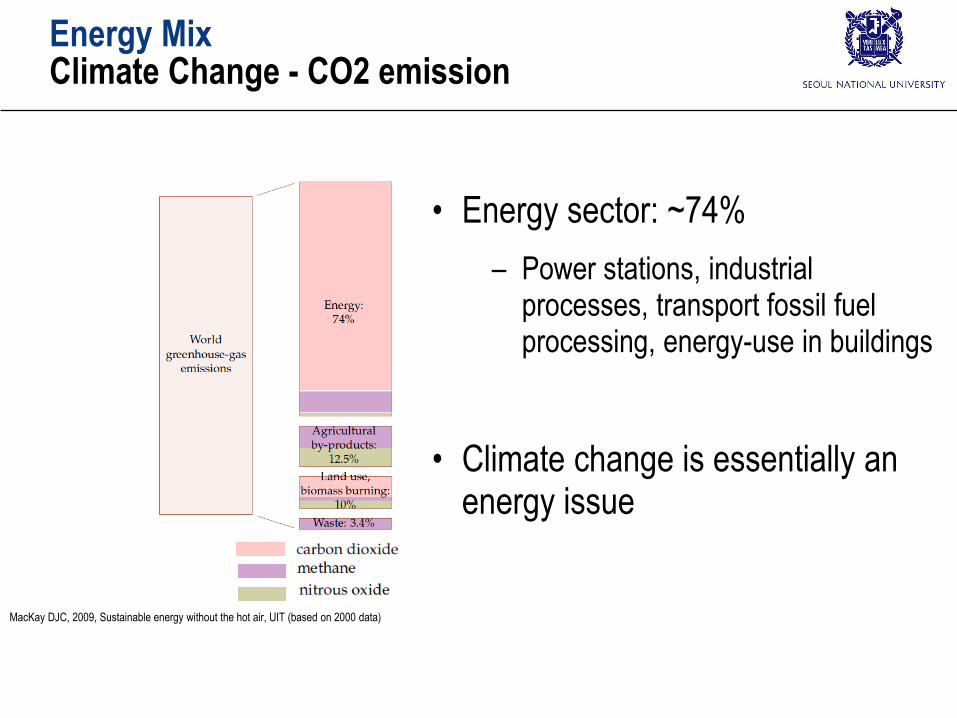
Energy MixClimate Change - CO2 emission
• Energy sector: ~74%
– Power stations, industrial processes, transport fossil fuel processing, energy-use in buildings
• Climate change is essentially an energy issue
MacKay DJC, 2009, Sustainable energy without the hot air, UIT (based on 2000 data)
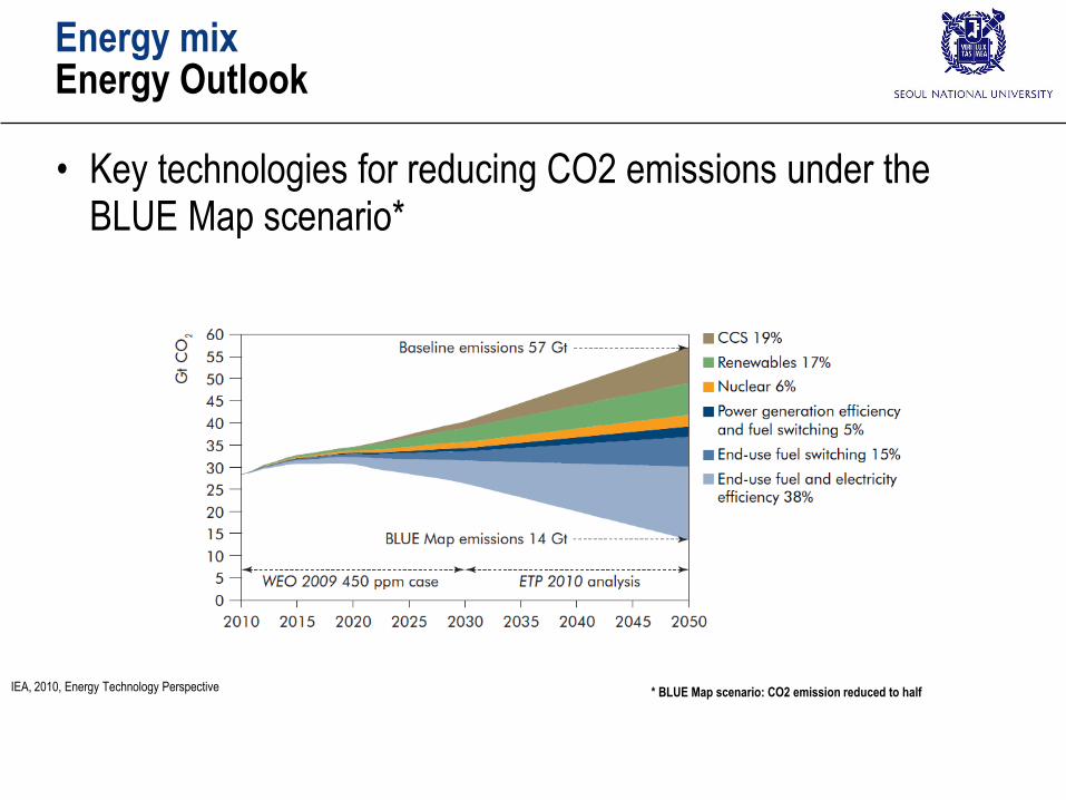
Energy mixEnergy Outlook
• Key technologies for reducing CO2 emissions under the BLUE Map scenario*
IEA, 2010, Energy Technology Perspective * BLUE Map scenario: CO2 emission reduced to half
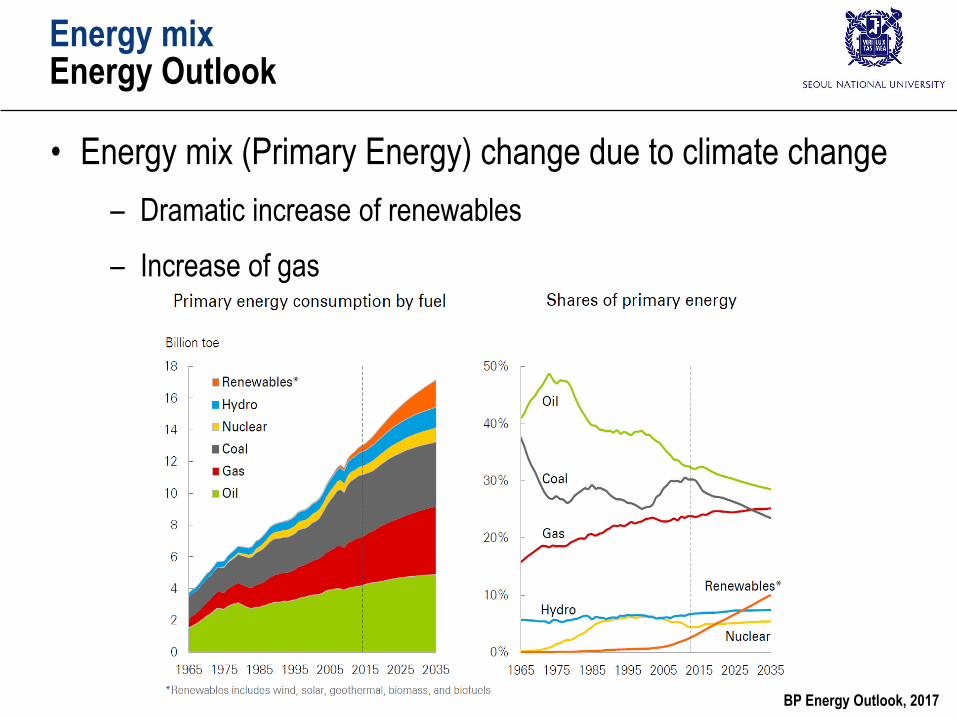
Energy mixEnergy Outlook
• Energy mix (Primary Energy) change due to climate change
– Dramatic increase of renewables
– Increase of gas
BP Energy Outlook, 2017
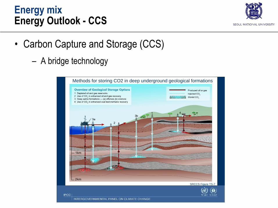
Energy mixEnergy Outlook - CCS
• Carbon Capture and Storage (CCS)
– A bridge technology
Methods for storing CO2 in deep underground geological formations
SRCCS Figure TS-7
Energy mixEnergy Outlook - CCS
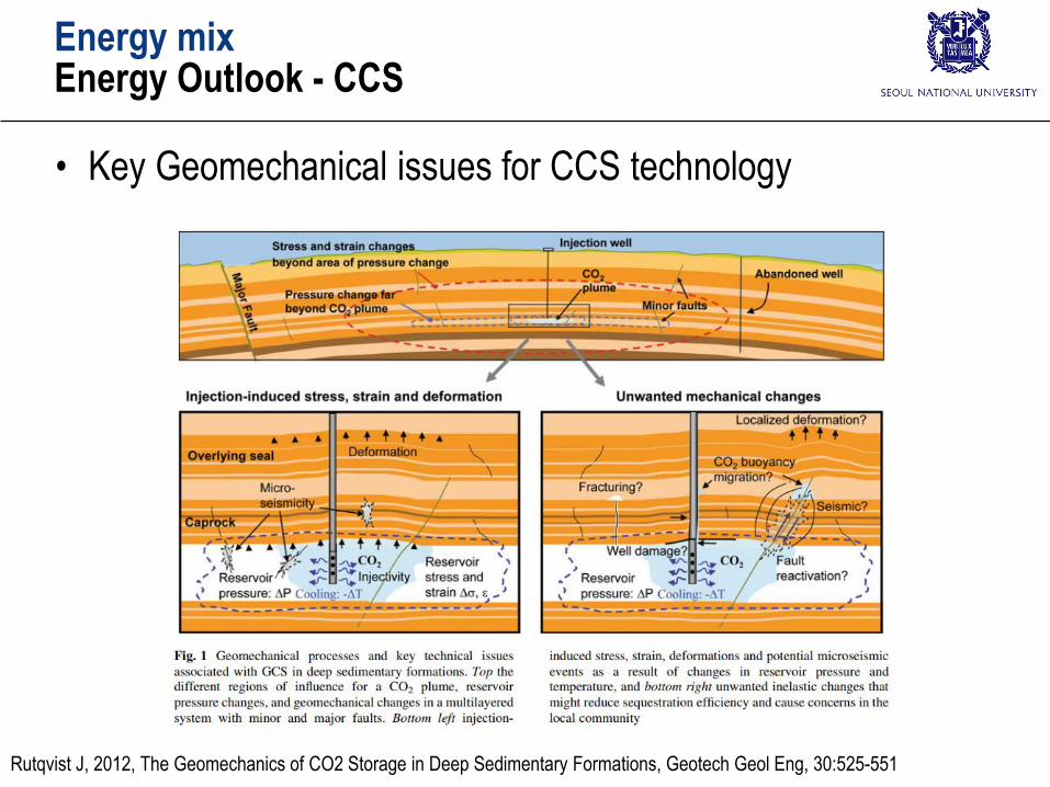
• Key Geomechanical issues for CCS technology
Rutqvist J, 2012, The Geomechanics of CO2 Storage in Deep Sedimentary Formations, Geotech Geol Eng, 30:525-551
Energy mixEnergy Outlook - CCS
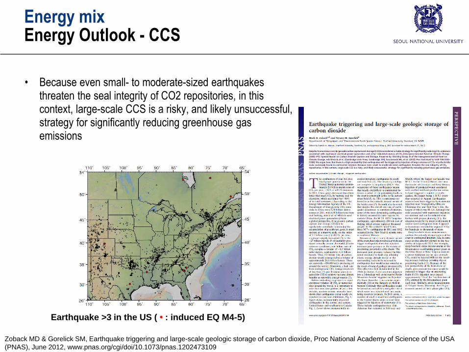
• Because even small- to moderate-sized earthquakes threaten the seal integrity of CO2 repositories, in this context, large-scale CCS is a risky, and likely unsuccessful, strategy for significantly reducing greenhouse gas emissions
Zoback MD & Gorelick SM, Earthquake triggering and large-scale geologic storage of carbon dioxide, Proc National Academy of Science of the USA
(PNAS), June 2012, www.pnas.org/cgi/doi/10.1073/pnas.1202473109
Earthquake >3 in the US ( • : induced EQ M4-5)
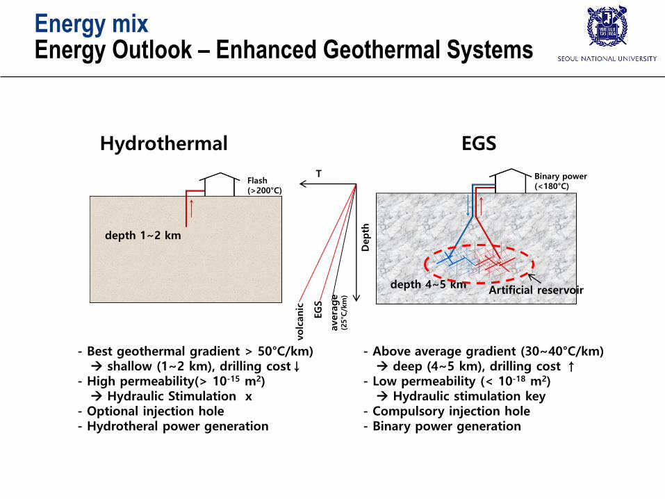
- Best geothermal gradient > 50°C/km) shallow (1~2 km), drilling cost↓
- High permeability(> 10-15 m2) Hydraulic Stimulation x
- Optional injection hole- Hydrotheral power generation
- Above average gradient (30~40°C/km) deep (4~5 km), drilling cost ↑
- Low permeability (< 10-18 m2) Hydraulic stimulation key
- Compulsory injection hole- Binary power generation
avera
ge
(25°C
/km
)
EG
S
volc
anic
depth 1~2 km
Depth
depth 4~5 km
T
Hydrothermal EGS
Flash (>200°C)
Binary power(<180°C)
Artificial reservoir
Energy mixEnergy Outlook – Enhanced Geothermal Systems
Energy mixEnergy Outlook – Enhanced Geothermal Systems
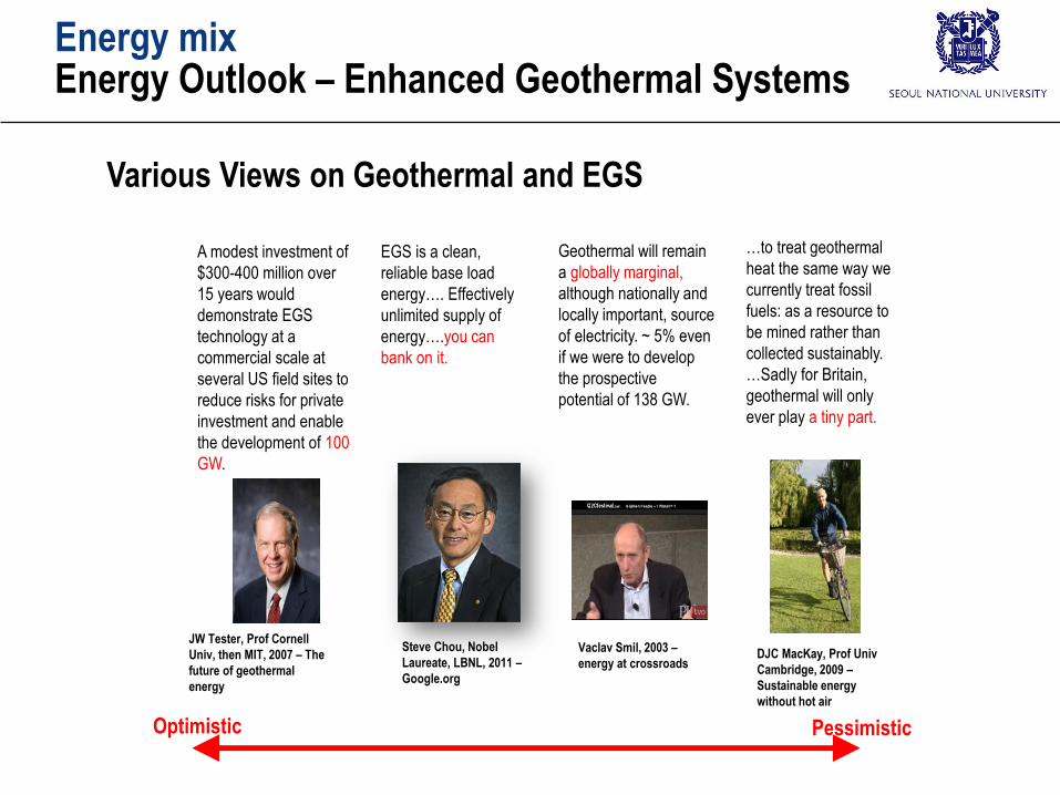
A modest investment of
$300-400 million over
15 years would
demonstrate EGS
technology at a
commercial scale at
several US field sites to
reduce risks for private
investment and enable
the development of 100
GW.
JW Tester, Prof Cornell
Univ, then MIT, 2007 – The
future of geothermal
energy
DJC MacKay, Prof Univ
Cambridge, 2009 –
Sustainable energy
without hot air
…to treat geothermal
heat the same way we
currently treat fossil
fuels: as a resource to
be mined rather than
collected sustainably.
…Sadly for Britain,
geothermal will only
ever play a tiny part.
Geothermal will remain
a globally marginal,
although nationally and
locally important, source
of electricity. ~ 5% even
if we were to develop
the prospective
potential of 138 GW.
Vaclav Smil, 2003 –
energy at crossroads
Steve Chou, Nobel
Laureate, LBNL, 2011 –
Google.org
EGS is a clean,
reliable base load
energy…. Effectively
unlimited supply of
energy….you can
bank on it.
Optimistic Pessimistic
Various Views on Geothermal and EGS
Unconventional ResourcesNatural Gas production
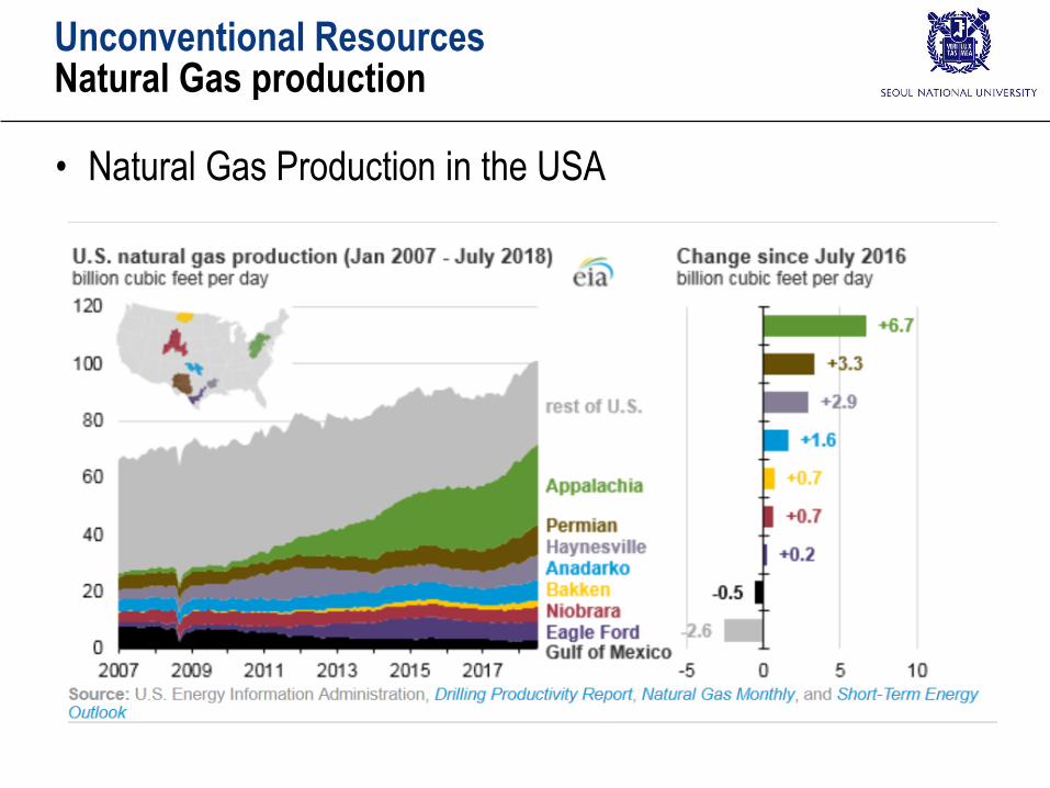
• Natural Gas Production in the USA
Unconventional ResourcesNatural Gas production
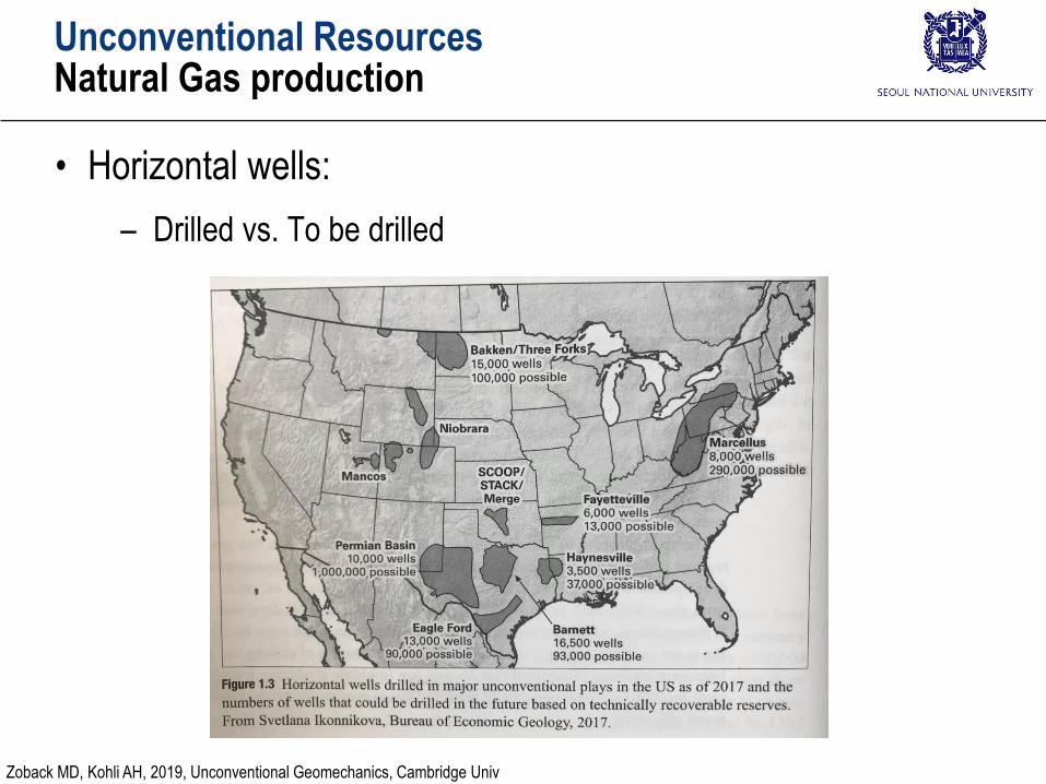
• Horizontal wells:
– Drilled vs. To be drilled
Zoback MD, Kohli AH, 2019, Unconventional Geomechanics, Cambridge Univ
Unconventional ResourcesNatural Gas production
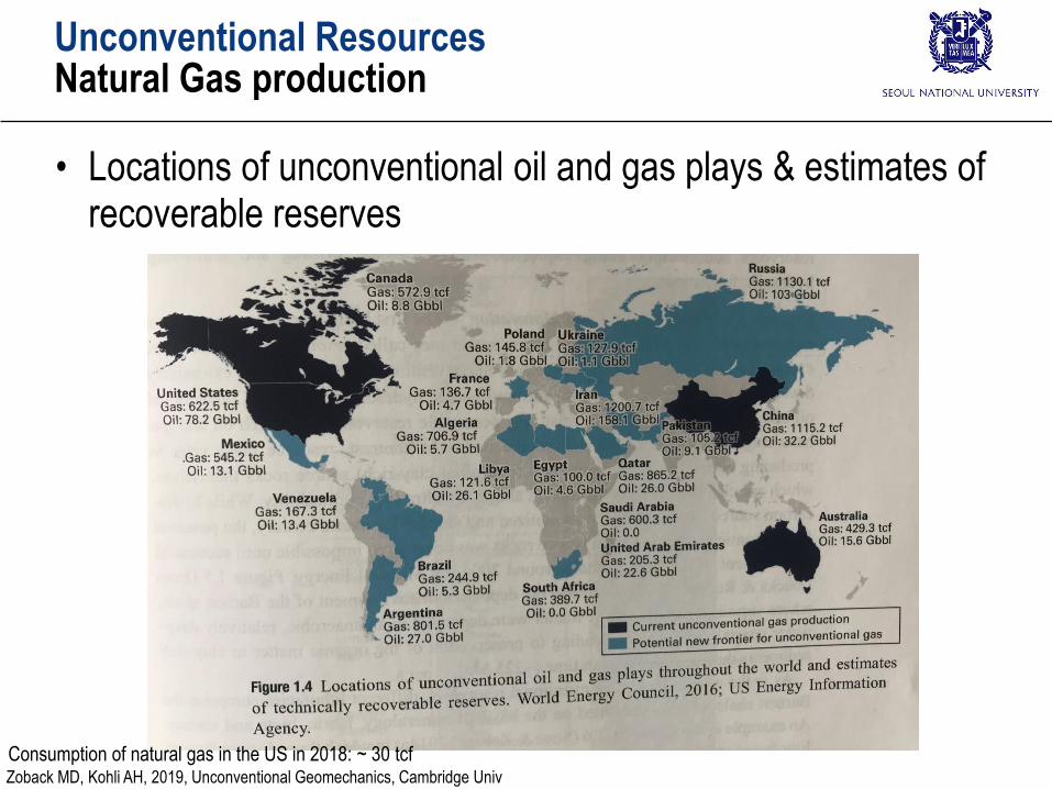
• Locations of unconventional oil and gas plays & estimates of recoverable reserves
Consumption of natural gas in the US in 2018: ~ 30 tcfZoback MD, Kohli AH, 2019, Unconventional Geomechanics, Cambridge Univ
Unconventional ResourcesPermeability
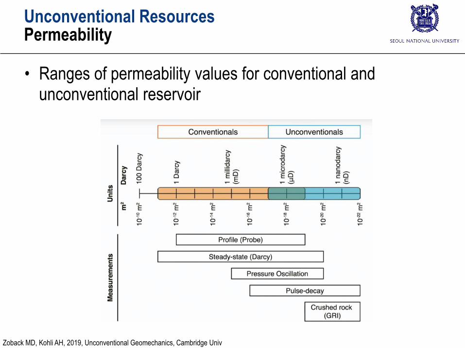
• Ranges of permeability values for conventional and unconventional reservoir
Zoback MD, Kohli AH, 2019, Unconventional Geomechanics, Cambridge Univ
Unconventional ResourcesPermeability
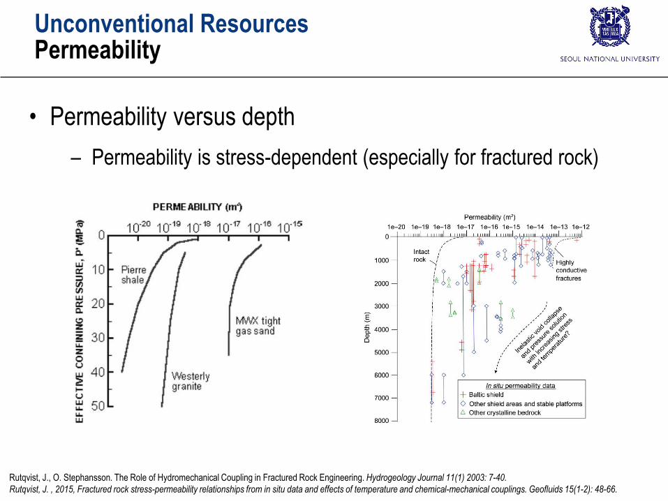
• Permeability versus depth
– Permeability is stress-dependent (especially for fractured rock)
Rutqvist, J., O. Stephansson. The Role of Hydromechanical Coupling in Fractured Rock Engineering. Hydrogeology Journal 11(1) 2003: 7-40.
Rutqvist, J. , 2015, Fractured rock stress-permeability relationships from in situ data and effects of temperature and chemical-mechanical couplings. Geofluids 15(1-2): 48-66.
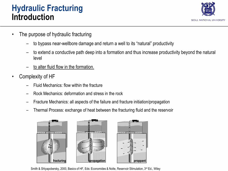
• The purpose of hydraulic fracturing
– to bypass near-wellbore damage and return a well to its “natural” productivity
– to extend a conductive path deep into a formation and thus increase productivity beyond the natural level
– to alter fluid flow in the formation.
• Complexity of HF
– Fluid Mechanics: flow within the fracture
– Rock Mechanics: deformation and stress in the rock
– Fracture Mechanics: all aspects of the failure and fracture initiation/propagation
– Thermal Process: exchange of heat between the fracturing fluid and the reservoir
proppantfracturing propagation
Smith & Shlyapobersky, 2000, Basics of HF, Eds: Economides & Nolte, Reservoir Stimulation, 3rd Ed., Wiley
Hydraulic FracturingIntroduction
Unconventional ResourcesHorizontal Drilling
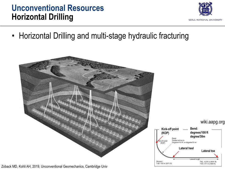
• Horizontal Drilling and multi-stage hydraulic fracturing
Lateral heelLateral toe
Kick-off point
(KOP)
Bend:
degrees/100 ft
degree/30m
wiki.aapg.org
Zoback MD, Kohli AH, 2019, Unconventional Geomechanics, Cambridge Univ
Unconventional ResourcesHorizontal Drilling
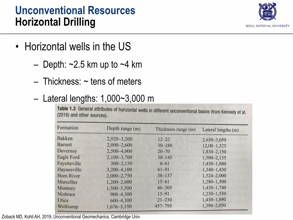
• Horizontal wells in the US
– Depth: ~2.5 km up to ~4 km
– Thickness: ~ tens of meters
– Lateral lengths: 1,000~3,000 m
Zoback MD, Kohli AH, 2019, Unconventional Geomechanics, Cambridge Univ
Unconventional ResourcesHorizontal Drilling
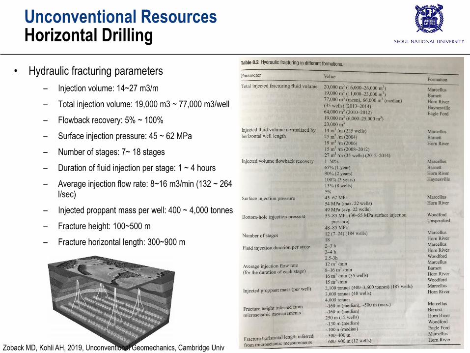
• Hydraulic fracturing parameters
– Injection volume: 14~27 m3/m
– Total injection volume: 19,000 m3 ~ 77,000 m3/well
– Flowback recovery: 5% ~ 100%
– Surface injection pressure: 45 ~ 62 MPa
– Number of stages: 7~ 18 stages
– Duration of fluid injection per stage: 1 ~ 4 hours
– Average injection flow rate: 8~16 m3/min (132 ~ 264 l/sec)
– Injected proppant mass per well: 400 ~ 4,000 tonnes
– Fracture height: 100~500 m
– Fracture horizontal length: 300~900 m
Zoback MD, Kohli AH, 2019, Unconventional Geomechanics, Cambridge Univ
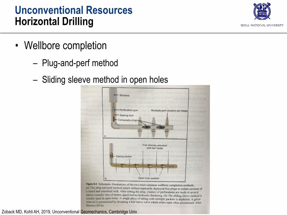
Unconventional ResourcesHorizontal Drilling
• Wellbore completion
– Plug-and-perf method
– Sliding sleeve method in open holes
Zoback MD, Kohli AH, 2019, Unconventional Geomechanics, Cambridge Univ
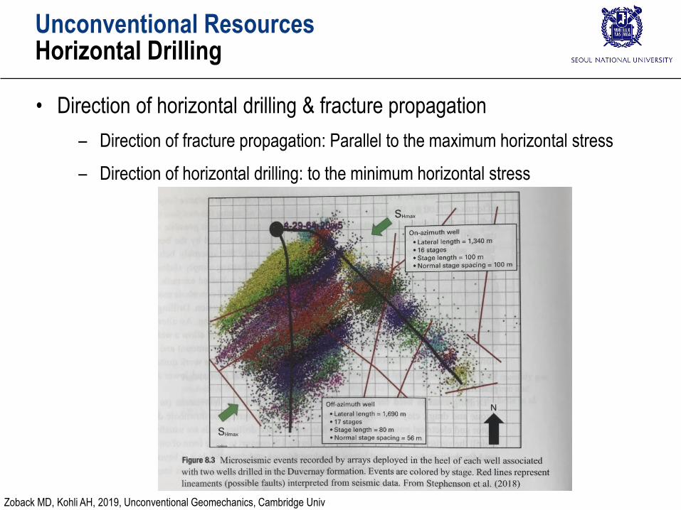
Unconventional ResourcesHorizontal Drilling
• Direction of horizontal drilling & fracture propagation
– Direction of fracture propagation: Parallel to the maximum horizontal stress
– Direction of horizontal drilling: to the minimum horizontal stress
Zoback MD, Kohli AH, 2019, Unconventional Geomechanics, Cambridge Univ
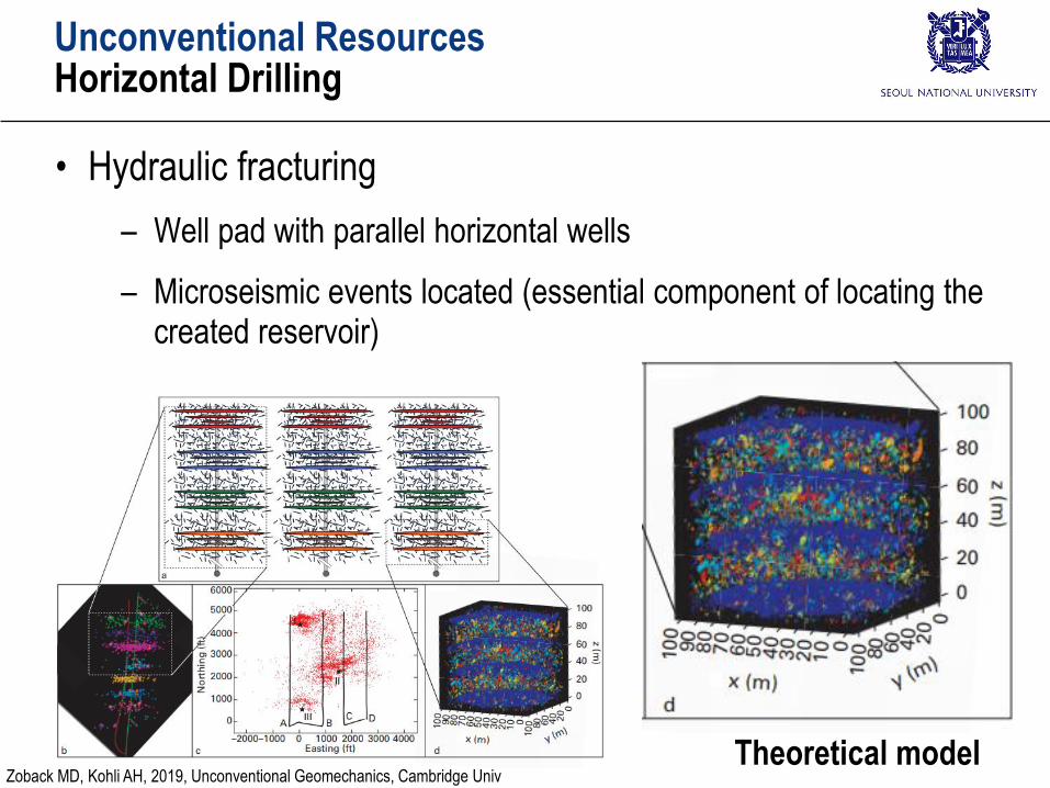
Unconventional ResourcesHorizontal Drilling
• Hydraulic fracturing
– Well pad with parallel horizontal wells
– Microseismic events located (essential component of locating the created reservoir)
Theoretical modelZoback MD, Kohli AH, 2019, Unconventional Geomechanics, Cambridge Univ
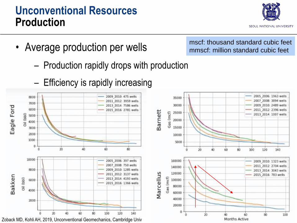
Unconventional ResourcesProduction
• Average production per wells
– Production rapidly drops with production
– Efficiency is rapidly increasing
mscf: thousand standard cubic feet
mmscf: million standard cubic feet
Zoback MD, Kohli AH, 2019, Unconventional Geomechanics, Cambridge Univ
maxHS
minhS
maxHS
minhS
maxHS
minhS
maxHS
minhS
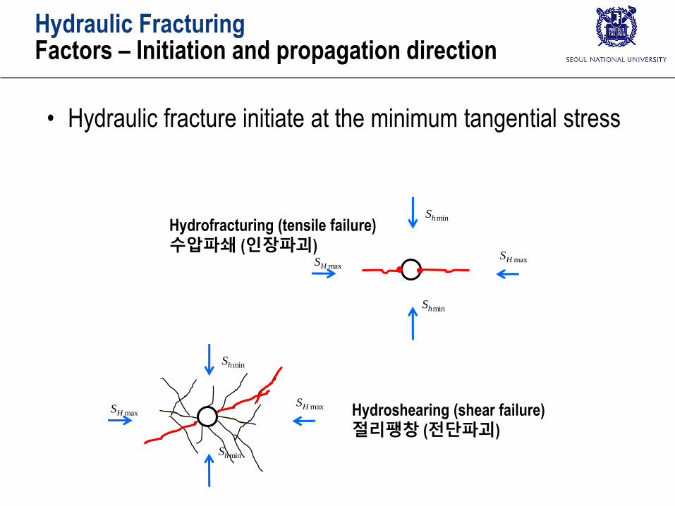
Hydroshearing (shear failure)
절리팽창 (전단파괴)
Hydrofracturing (tensile failure)
수압파쇄 (인장파괴)
Hydraulic FracturingFactors – Initiation and propagation direction
• Hydraulic fracture initiate at the minimum tangential stress
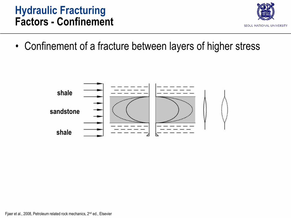
Hydraulic FracturingFactors - Confinement
• Confinement of a fracture between layers of higher stress
sandstone
shale
shale
Fjaer et al., 2008, Petroleum related rock mechanics, 2nd ed., Elsevier
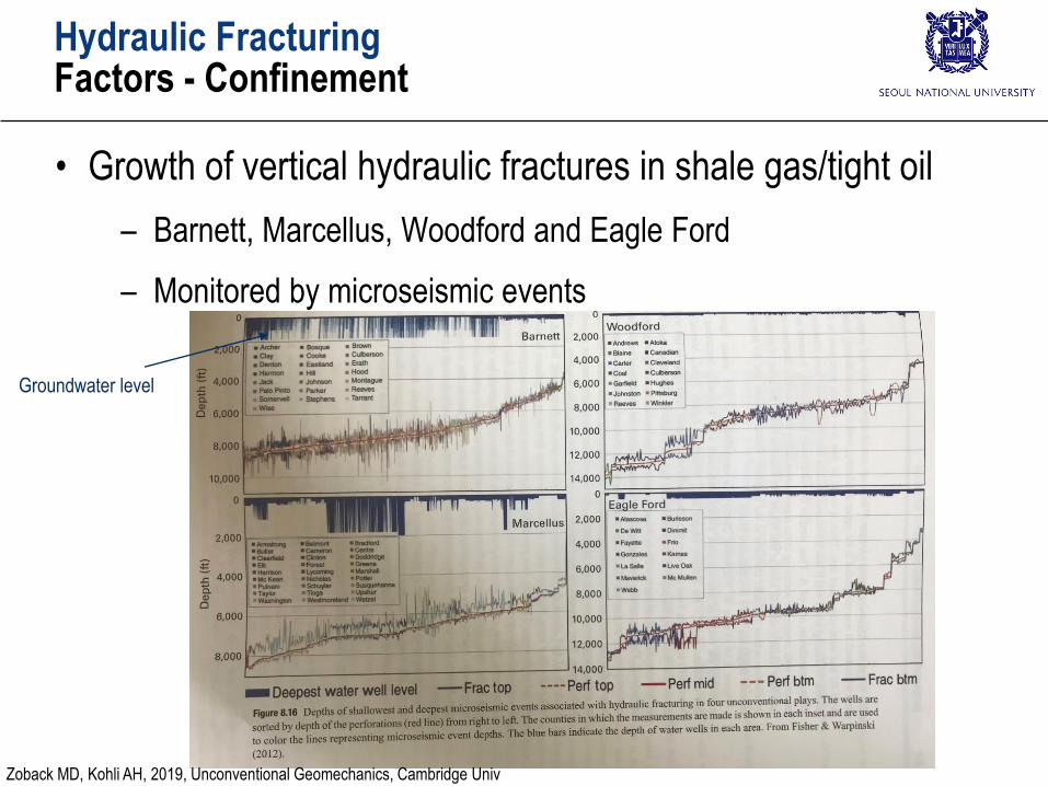
Hydraulic FracturingFactors - Confinement
• Growth of vertical hydraulic fractures in shale gas/tight oil
– Barnett, Marcellus, Woodford and Eagle Ford
– Monitored by microseismic events
Groundwater level
Zoback MD, Kohli AH, 2019, Unconventional Geomechanics, Cambridge Univ
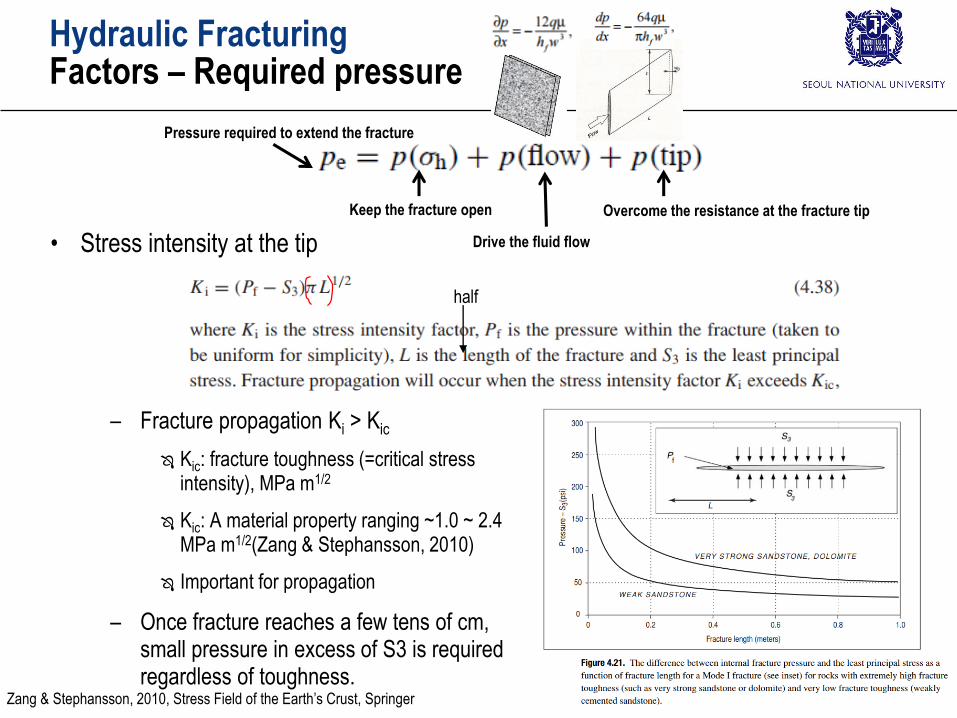
Hydraulic FracturingFactors – Required pressure
• Stress intensity at the tip
– Fracture propagation Ki > Kic
Kic: fracture toughness (=critical stress intensity), MPa m1/2
Kic: A material property ranging ~1.0 ~ 2.4 MPa m1/2(Zang & Stephansson, 2010)
Important for propagation
– Once fracture reaches a few tens of cm, small pressure in excess of S3 is required regardless of toughness.
Zang & Stephansson, 2010, Stress Field of the Earth’s Crust, Springer
half
Pressure required to extend the fracture
Keep the fracture open
Drive the fluid flow
Overcome the resistance at the fracture tip
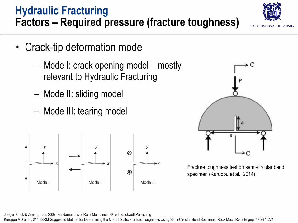
Hydraulic FracturingFactors – Required pressure (fracture toughness)
• Crack-tip deformation mode
– Mode I: crack opening model – mostly relevant to Hydraulic Fracturing
– Mode II: sliding model
– Mode III: tearing model
Jaeger, Cook & Zimmerman, 2007, Fundamentals of Rock Mechanics, 4th ed, Blackwell Publishing
Kuruppu MD et al., 214, ISRM-Suggested Method for Determining the Mode I Static Fracture Toughness Using Semi-Circular Bend Specimen, Rock Mech Rock Engng, 47:267–274
Fracture toughness test on semi-circular bend
specimen (Kuruppu et al., 2014)
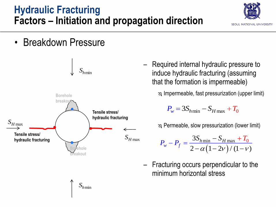
• Breakdown Pressure
Hydraulic FracturingFactors – Initiation and propagation direction
– Required internal hydraulic pressure to induce hydraulic fracturing (assuming that the formation is impermeable)
Impermeable, fast pressurization (upper limit)
Permeable, slow pressurization (lower limit)
– Fracturing occurs perpendicular to the minimum horizontal stress
maxHS
minhS
maxHS
minhS
Tensile stress/
hydraulic fracturing
Borehole
breakout
Borehole
breakout
Tensile stress/
hydraulic fracturing
min ax 0m3 h HwP S TS
min max 03
2 1 2 / (1 )
hw
Hf
S TP
SP
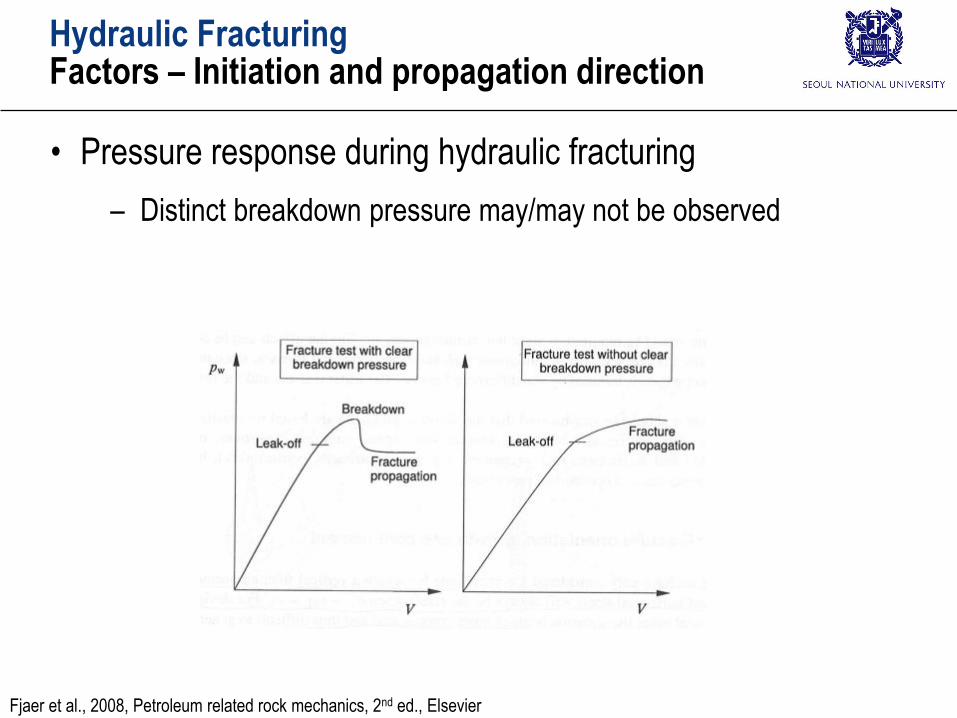
Hydraulic FracturingFactors – Initiation and propagation direction
• Pressure response during hydraulic fracturing
– Distinct breakdown pressure may/may not be observed
Fjaer et al., 2008, Petroleum related rock mechanics, 2nd ed., Elsevier

Hydraulic FracturingFactors – Initiation and propagation direction
Fracture parallel to the borehole Fracture normal to the borehole
Fjaer et al., 2008, Petroleum related rock mechanics, 2nd ed., Elsevier
• Hydraulic fracture propagate normal to the minimum stress
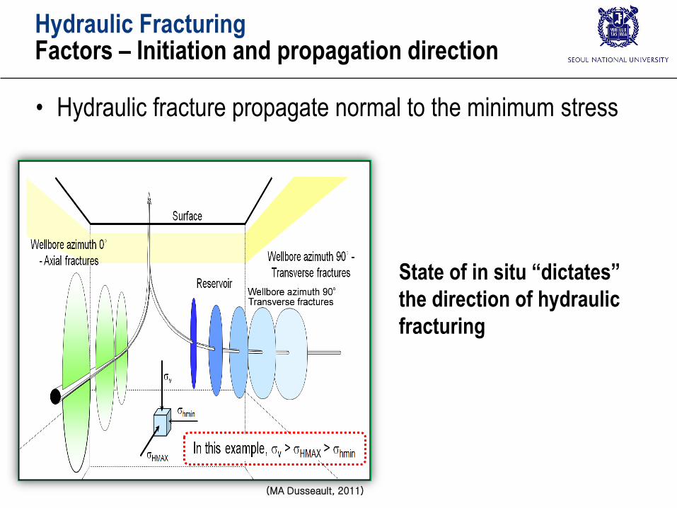
Hydraulic FracturingFactors – Initiation and propagation direction
(MA Dusseault, 2011)
State of in situ “dictates”
the direction of hydraulic
fracturing
• Hydraulic fracture propagate normal to the minimum stress
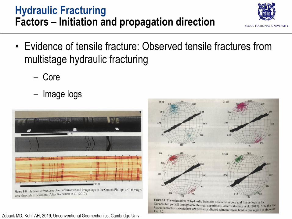
Hydraulic FracturingFactors – Initiation and propagation direction
• Evidence of tensile fracture: Observed tensile fractures from multistage hydraulic fracturing
– Core
– Image logs
Zoback MD, Kohli AH, 2019, Unconventional Geomechanics, Cambridge Univ
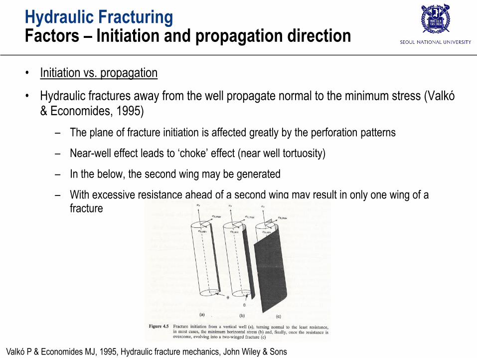
Hydraulic FracturingFactors – Initiation and propagation direction
• Initiation vs. propagation
• Hydraulic fractures away from the well propagate normal to the minimum stress (Valkó& Economides, 1995)
– The plane of fracture initiation is affected greatly by the perforation patterns
– Near-well effect leads to ‘choke’ effect (near well tortuosity)
– In the below, the second wing may be generated
– With excessive resistance ahead of a second wing may result in only one wing of a fracture
Valkó P & Economides MJ, 1995, Hydraulic fracture mechanics, John Wiley & Sons

Hydraulic FracturingFactors – Initiation and propagation direction
• Initiation vs. propagation
• Direction of fracture initiation and propagation is closely related to the production characteristics (Valkó & Economides, 1995)
– Vertical well – vertical fracture: linear flow
– Horizontal well – transverse vertical fracture: linear + radial flow
Although radial flow reduce the production, composite flowrates from multiple treatment is larger than from a single fracture
– Entry from the well to the fracture needs to be minimized
Problem in the right can happen even if drilling was properly
Transverse fracture from a horizontal well Turning from longitudinal initiation to transverse direction
Valkó P & Economides MJ, 1995, Hydraulic fracture mechanics, John Wiley & Sons
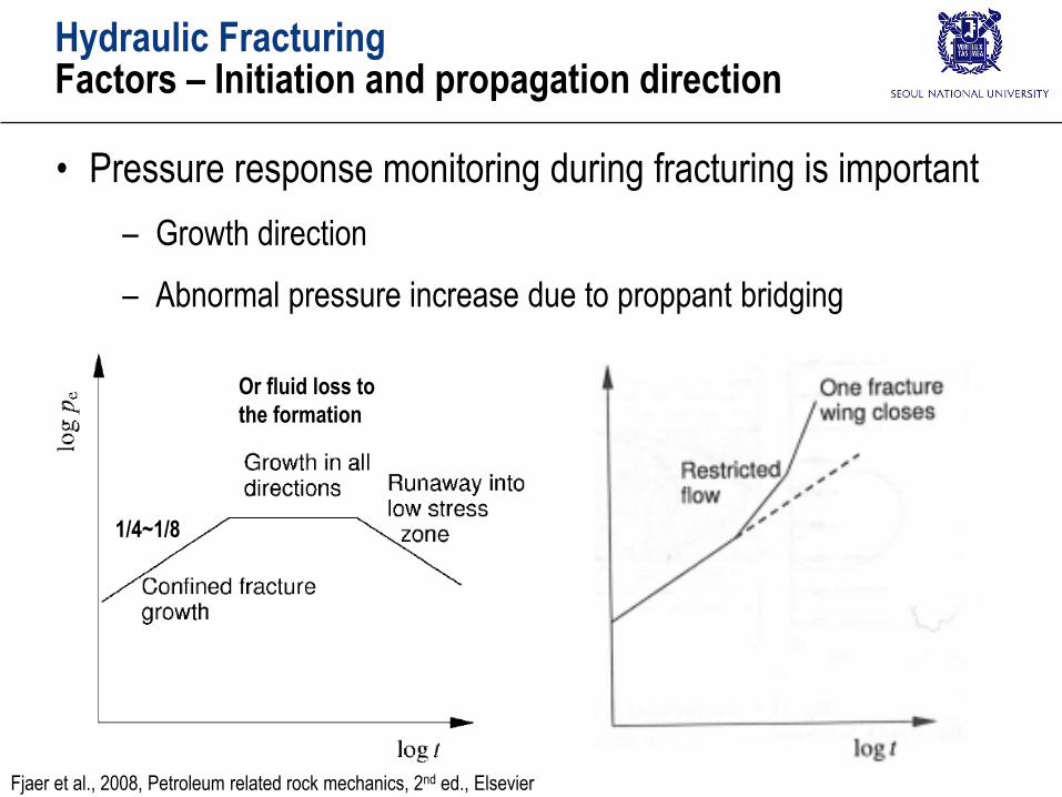
Hydraulic FracturingFactors – Initiation and propagation direction
• Pressure response monitoring during fracturing is important
– Growth direction
– Abnormal pressure increase due to proppant bridging
Fjaer et al., 2008, Petroleum related rock mechanics, 2nd ed., Elsevier
1/4~1/8
Or fluid loss to
the formation
Hydraulic FracturingModels of hydraulic fracturing
• Models of hydraulic fracturing
– Economic optimization
– Design of a pump schedule
– Simulation of the fracture geometry and proppant placement
– Evaluation of treatment
comparison of prediction with actual behavior
– Estimation of fluid volume and proppant to create a fracture with a desired conductivity and geometry
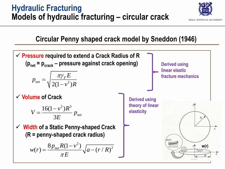
Hydraulic FracturingModels of hydraulic fracturing – circular crack
Pressure required to extend a Crack Radius of R
(pnet = pcrack – pressure against crack opening)
Volume of Crack
Width of a Static Penny-shaped Crack
(R = penny-shaped crack radius)
Circular Penny shaped crack model by Sneddon (1946)
22(1 )
Fnet
Ep
v R
Derived using
theory of linear
elasticity
Derived using
linear elastic
fracture mechanics
228 (1 )
( ) ( / )netp R vw r a r R
E
2 316(1 )
3net
v RV p
E
w(r)
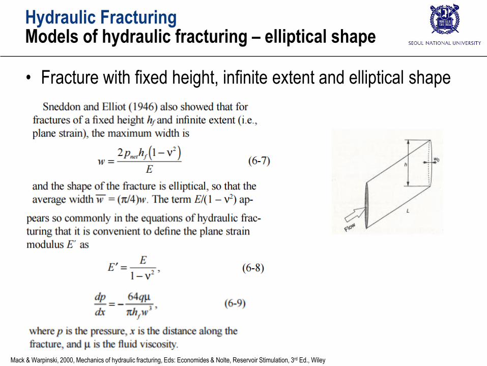
Hydraulic FracturingModels of hydraulic fracturing – elliptical shape
• Fracture with fixed height, infinite extent and elliptical shape
Mack & Warpinski, 2000, Mechanics of hydraulic fracturing, Eds: Economides & Nolte, Reservoir Stimulation, 3rd Ed., Wiley
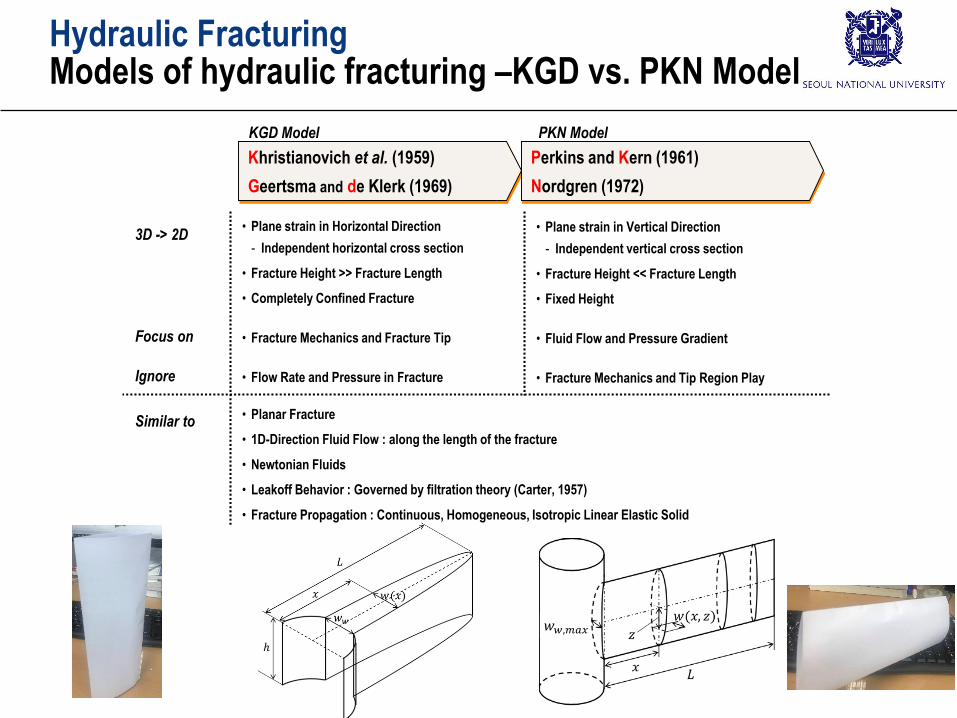
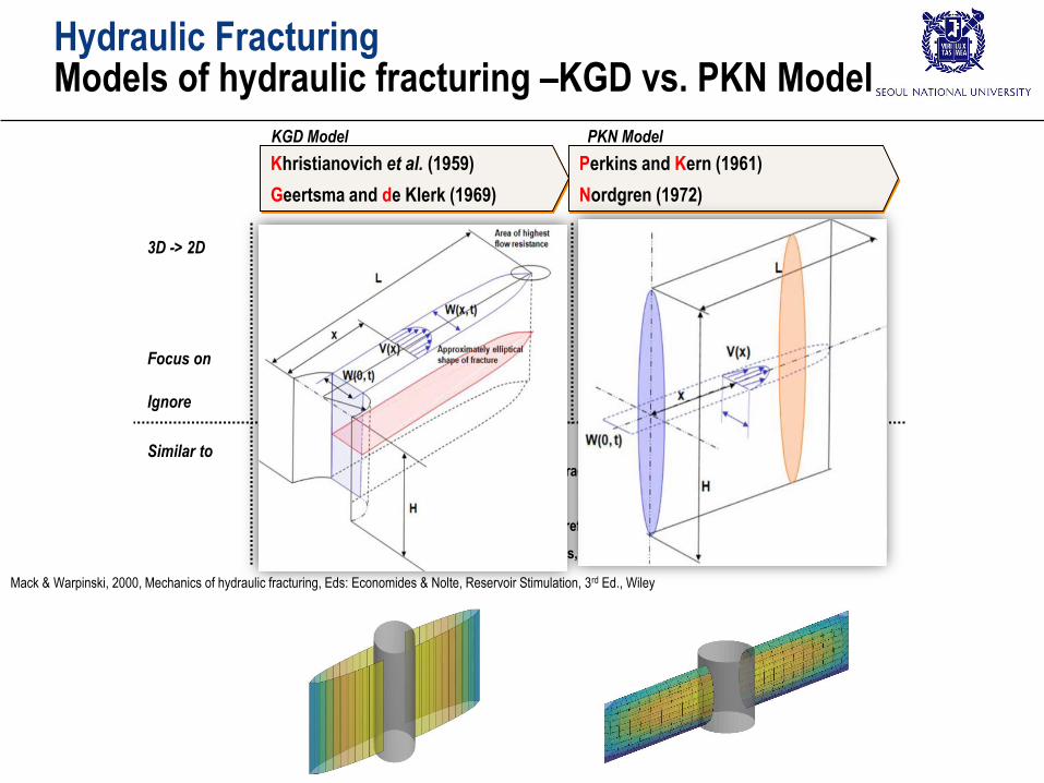
Hydraulic FracturingModels of hydraulic fracturing –KGD vs. PKN Model
3D -> 2D
Khristianovich et al. (1959)
Geertsma and de Klerk (1969)
• Plane strain in Horizontal Direction
- Independent horizontal cross section
• Fracture Height >> Fracture Length
• Completely Confined Fracture
• Fracture Mechanics and Fracture Tip
• Flow Rate and Pressure in Fracture
KGD Model PKN Model
Perkins and Kern (1961)
Nordgren (1972)
• Plane strain in Vertical Direction
- Independent vertical cross section
• Fracture Height << Fracture Length
• Fixed Height
• Fluid Flow and Pressure Gradient
• Fracture Mechanics and Tip Region Play
Focus on
Ignore
Similar to• Planar Fracture
• 1D-Direction Fluid Flow : along the length of the fracture
• Newtonian Fluids
• Leakoff Behavior : Governed by filtration theory (Carter, 1957)
• Fracture Propagation : Continuous, Homogeneous, Isotropic Linear Elastic Solid
𝑤𝑤,𝑚𝑎𝑥
Hydraulic FracturingModels of hydraulic fracturing –KGD vs. PKN Model
3D -> 2D
Khristianovich et al. (1959)
Geertsma and de Klerk (1969)
• Plane strain in Horizontal Direction
- Independent horizontal cross section
• Fracture Height >> Fracture Length
• Completely Confined Fracture
• Fracture Mechanics and Fracture Tip
• Flow Rate and Pressure in Fracture
KGD Model PKN Model
Perkins and Kern (1961)
Nordgren (1972)
• Plane strain in Vertical Direction
- Independent vertical cross section
• Fracture Height << Fracture Length
• Fixed Height
• Fluid Flow and Pressure Gradient
• Fracture Mechanics and Tip Region Play
Focus on
Ignore
Similar to• Planar Fracture
• 1D-Direction Fluid Flow : along the length of the fracture
• Newtonian Fluids
• Leakoff Behavior : Governed by filtration theory (refer to Carter(1957))
• Fracture Propagation : Continuous, Homogeneous, Isotropic Linear Elastic Solid
Mack & Warpinski, 2000, Mechanics of hydraulic fracturing, Eds: Economides & Nolte, Reservoir Stimulation, 3rd Ed., Wiley
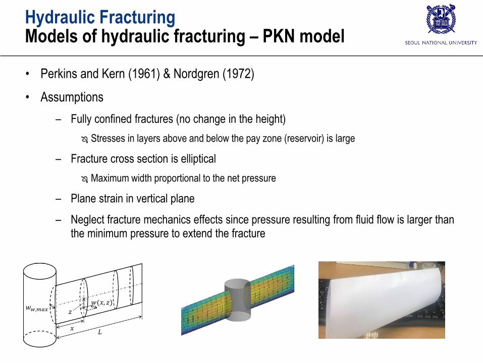
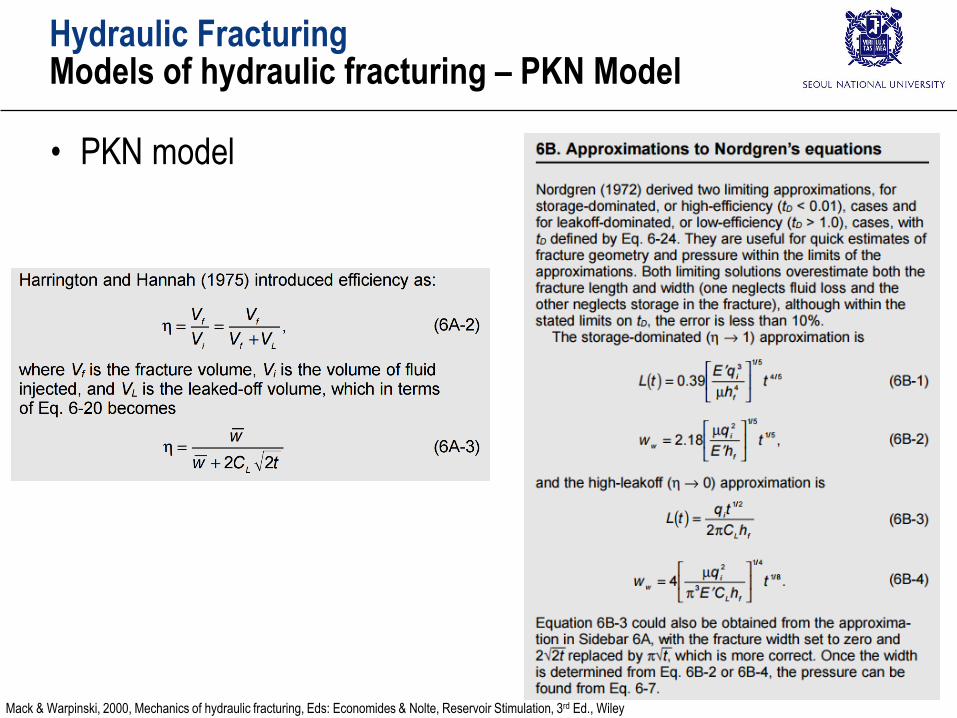
Hydraulic FracturingModels of hydraulic fracturing – PKN model
• Perkins and Kern (1961) & Nordgren (1972)
• Assumptions
– Fully confined fractures (no change in the height)
Stresses in layers above and below the pay zone (reservoir) is large
– Fracture cross section is elliptical
Maximum width proportional to the net pressure
– Plane strain in vertical plane
– Neglect fracture mechanics effects since pressure resulting from fluid flow is larger than the minimum pressure to extend the fracture
𝑤𝑤,𝑚𝑎𝑥
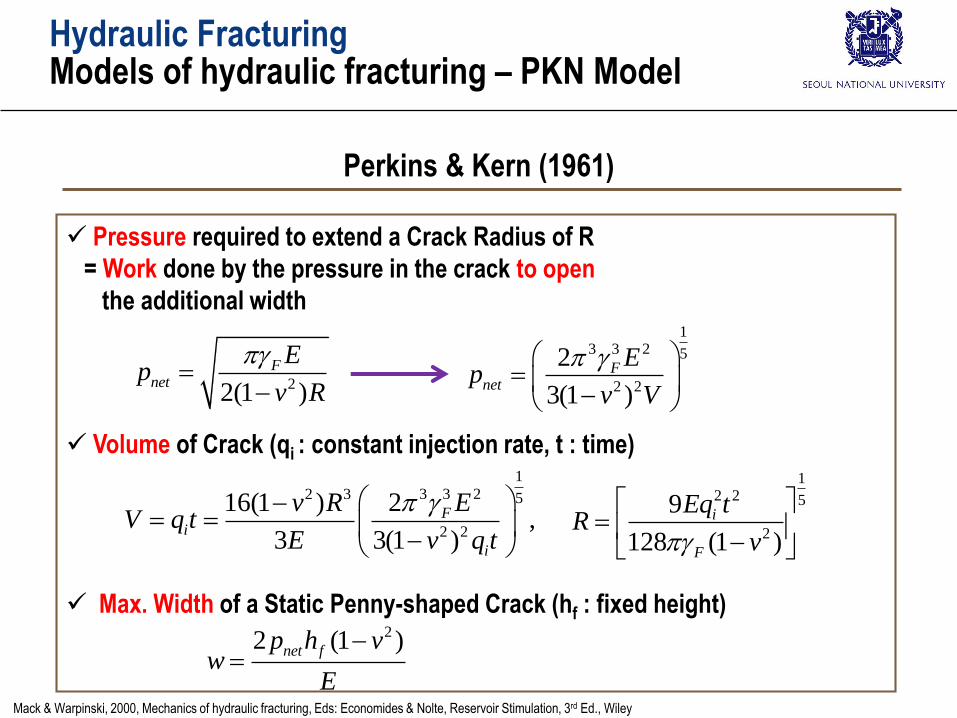
Hydraulic FracturingModels of hydraulic fracturing – PKN Model
Pressure required to extend a Crack Radius of R
= Work done by the pressure in the crack to open
the additional width
Volume of Crack (qi : constant injection rate, t : time)
Max. Width of a Static Penny-shaped Crack (hf : fixed height)
Perkins & Kern (1961)
22(1 )
Fnet
Ep
v R
22 (1 )net fp h vw
E
1
3 3 22 3 5
2 2
216(1 ),
3 3(1 )
Fi
i
Ev RV q t
E v q t
13 3 2 5
2 2
2
3(1 )
Fnet
Ep
v V
12 2 5
2
9
128 (1 )
i
F
Eq tR
v
Mack & Warpinski, 2000, Mechanics of hydraulic fracturing, Eds: Economides & Nolte, Reservoir Stimulation, 3rd Ed., Wiley
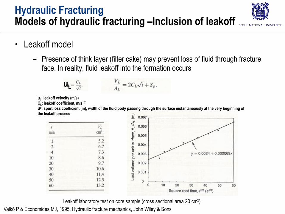
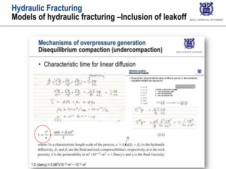
Hydraulic FracturingModels of hydraulic fracturing –Inclusion of leakoff
• Leakoff model
– Presence of think layer (filter cake) may prevent loss of fluid through fracture face. In reality, fluid leakoff into the formation occurs
Leakoff laboratory test on core sample (cross sectional area 20 cm2)
Valkó P & Economides MJ, 1995, Hydraulic fracture mechanics, John Wiley & Sons
uL: leakoff velocity (m/s)
CL: leakoff coefficient, m/s1/2
Sp: spurt loss coefficient (m), width of the fluid body passing through the surface instantaneously at the very beginning of
the leakoff process
uL
Hydraulic FracturingModels of hydraulic fracturing –Inclusion of leakoff
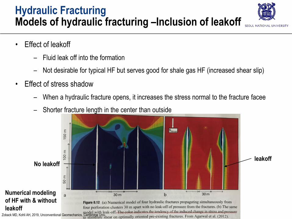
Hydraulic FracturingModels of hydraulic fracturing –Inclusion of leakoff
• Effect of leakoff
– Fluid leak off into the formation
– Not desirable for typical HF but serves good for shale gas HF (increased shear slip)
• Effect of stress shadow
– When a hydraulic fracture opens, it increases the stress normal to the fracture facee
– Shorter fracture length in the center than outside
No leakoffleakoff
Numerical modeling
of HF with & without
leakoffZoback MD, Kohli AH, 2019, Unconventional Geomechanics, Cambridge Univ
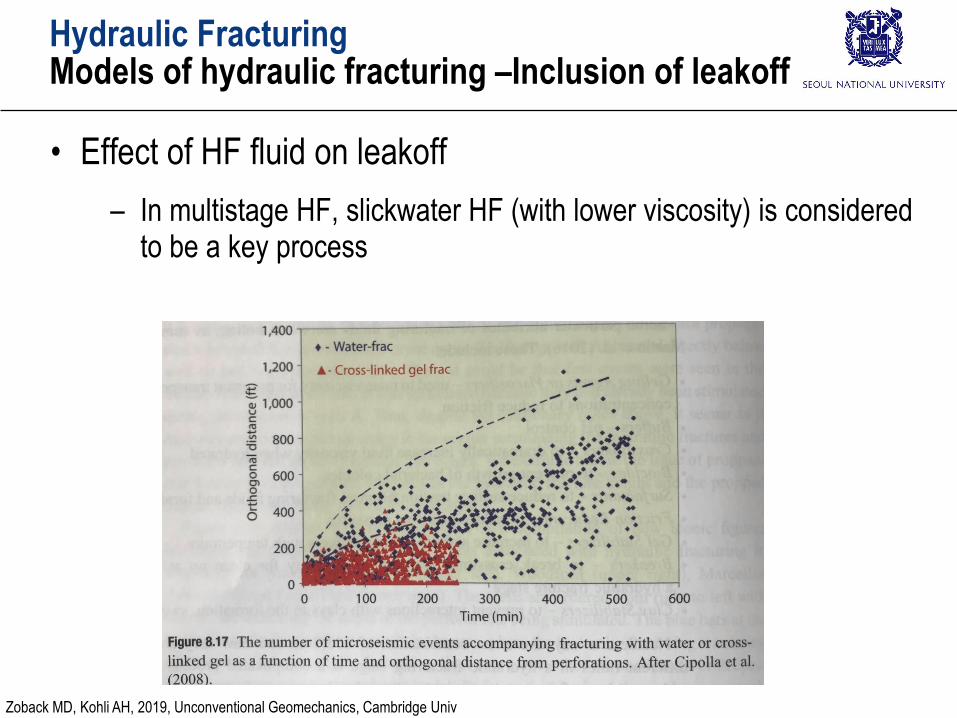
Hydraulic FracturingModels of hydraulic fracturing –Inclusion of leakoff
• Effect of HF fluid on leakoff
– In multistage HF, slickwater HF (with lower viscosity) is considered to be a key process
Zoback MD, Kohli AH, 2019, Unconventional Geomechanics, Cambridge Univ
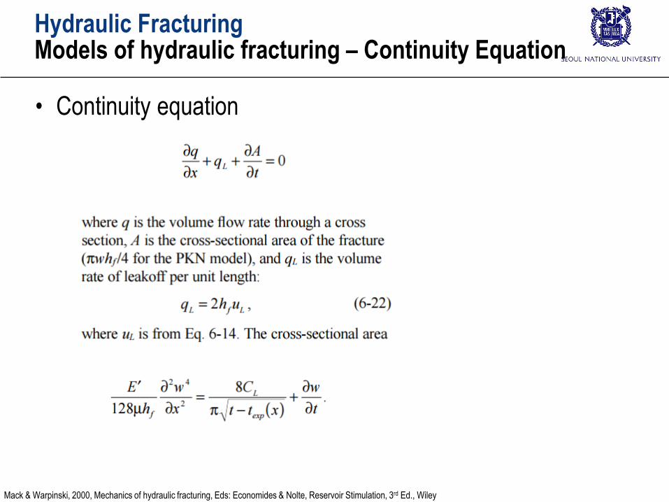
Hydraulic FracturingModels of hydraulic fracturing – Continuity Equation
• Continuity equation
Mack & Warpinski, 2000, Mechanics of hydraulic fracturing, Eds: Economides & Nolte, Reservoir Stimulation, 3rd Ed., Wiley
Hydraulic FracturingModels of hydraulic fracturing – PKN Model
• PKN model
Mack & Warpinski, 2000, Mechanics of hydraulic fracturing, Eds: Economides & Nolte, Reservoir Stimulation, 3rd Ed., Wiley
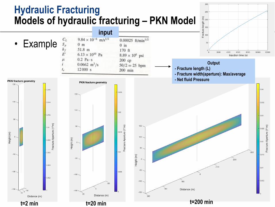
Hydraulic FracturingModels of hydraulic fracturing – PKN Model
• Example
t=2 min t=20 min t=200 min
input
Output
- Fracture length (L)
- Fracture width(aperture): Max/average
- Net fluid Pressure
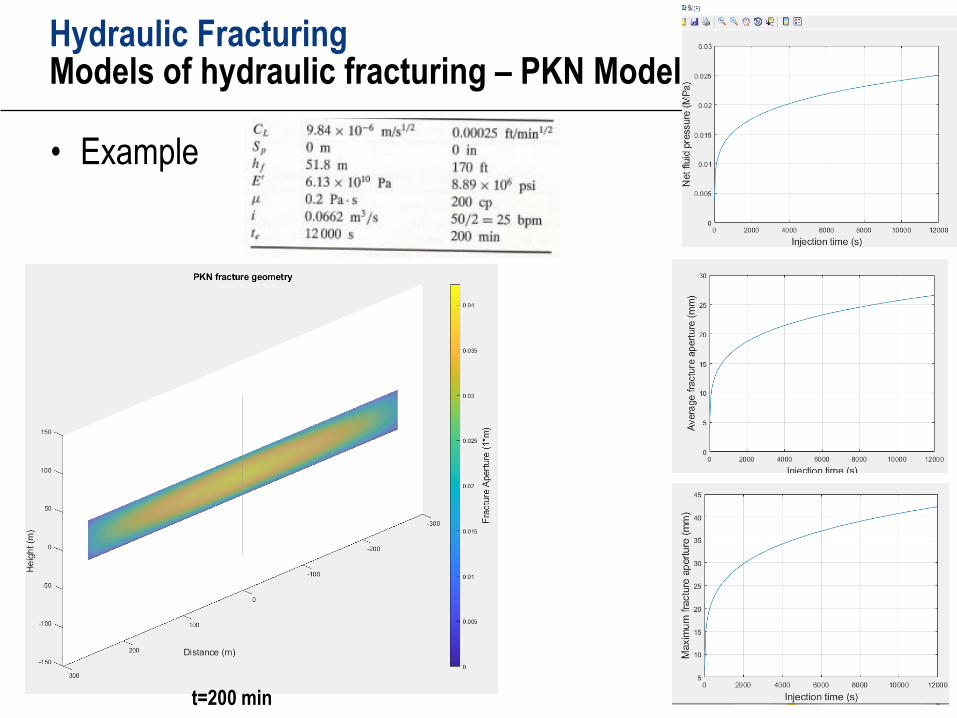
Hydraulic FracturingModels of hydraulic fracturing – PKN Model
• Example
t=200 min
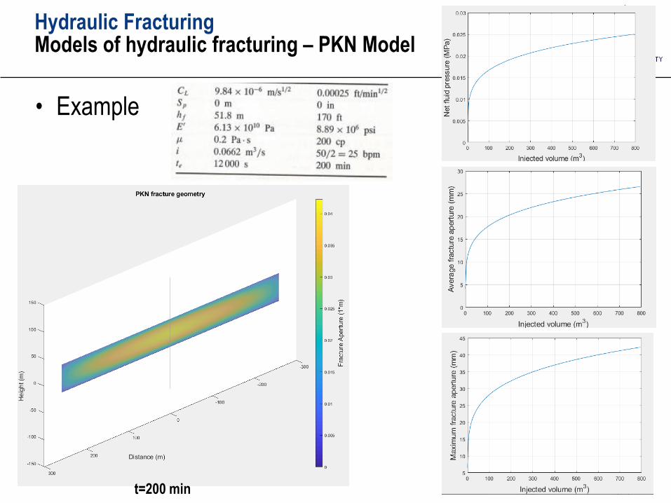
Hydraulic FracturingModels of hydraulic fracturing – PKN Model
• Example
t=200 min
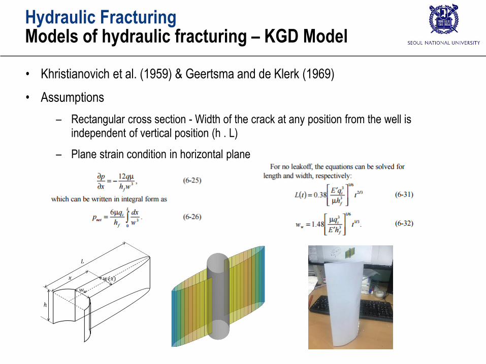
Hydraulic FracturingModels of hydraulic fracturing – KGD Model
• Khristianovich et al. (1959) & Geertsma and de Klerk (1969)
• Assumptions
– Rectangular cross section - Width of the crack at any position from the well is independent of vertical position (h . L)
– Plane strain condition in horizontal plane
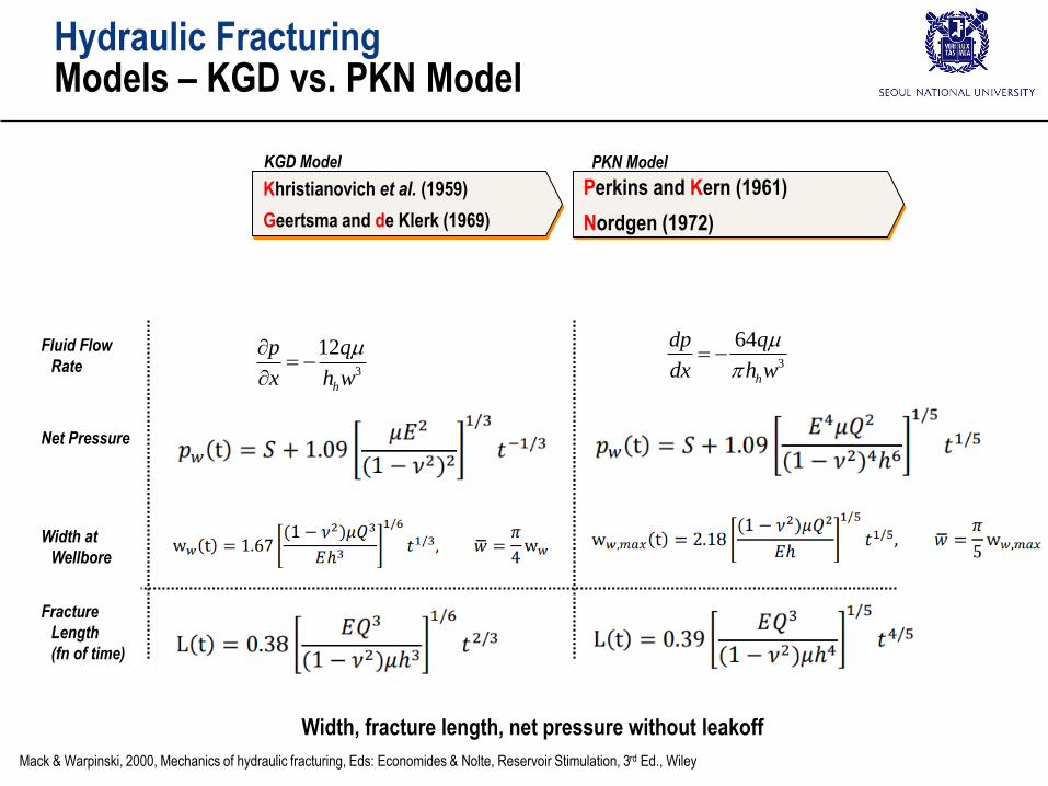
Hydraulic FracturingModels – KGD vs. PKN Model
Fluid Flow
Rate
Khristianovich et al. (1959)
Geertsma and de Klerk (1969)
KGD Model PKN Model
Perkins and Kern (1961)
Nordgen (1972)
Net Pressure
Width at
Wellbore
Fracture
Length
(fn of time)
3
64
h
dp q
dx h w
3
12
h
p q
x h w
Mack & Warpinski, 2000, Mechanics of hydraulic fracturing, Eds: Economides & Nolte, Reservoir Stimulation, 3rd Ed., Wiley
Width, fracture length, net pressure without leakoff
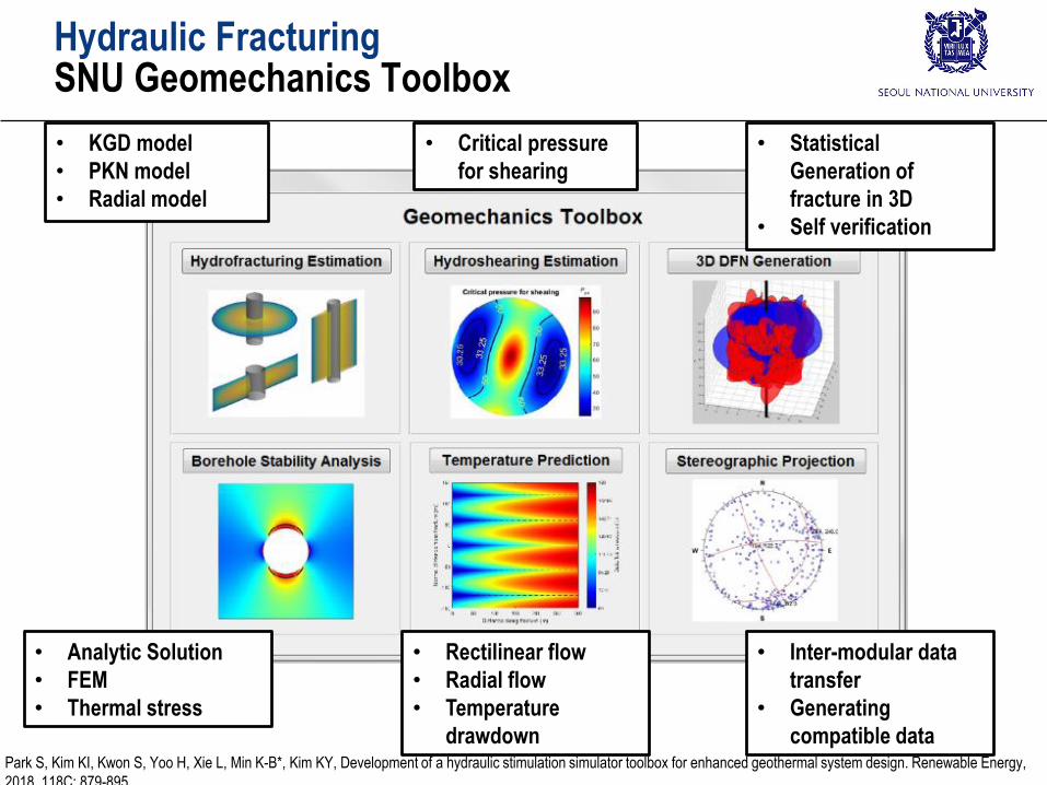
Hydraulic FracturingSNU Geomechanics Toolbox
• KGD model
• PKN model
• Radial model
• Critical pressure
for shearing
• Statistical
Generation of
fracture in 3D
• Self verification
• Analytic Solution
• FEM
• Thermal stress
• Rectilinear flow
• Radial flow
• Temperature
drawdown
• Inter-modular data
transfer
• Generating
compatible dataPark S, Kim KI, Kwon S, Yoo H, Xie L, Min K-B*, Kim KY, Development of a hydraulic stimulation simulator toolbox for enhanced geothermal system design. Renewable Energy,
2018, 118C: 879-895
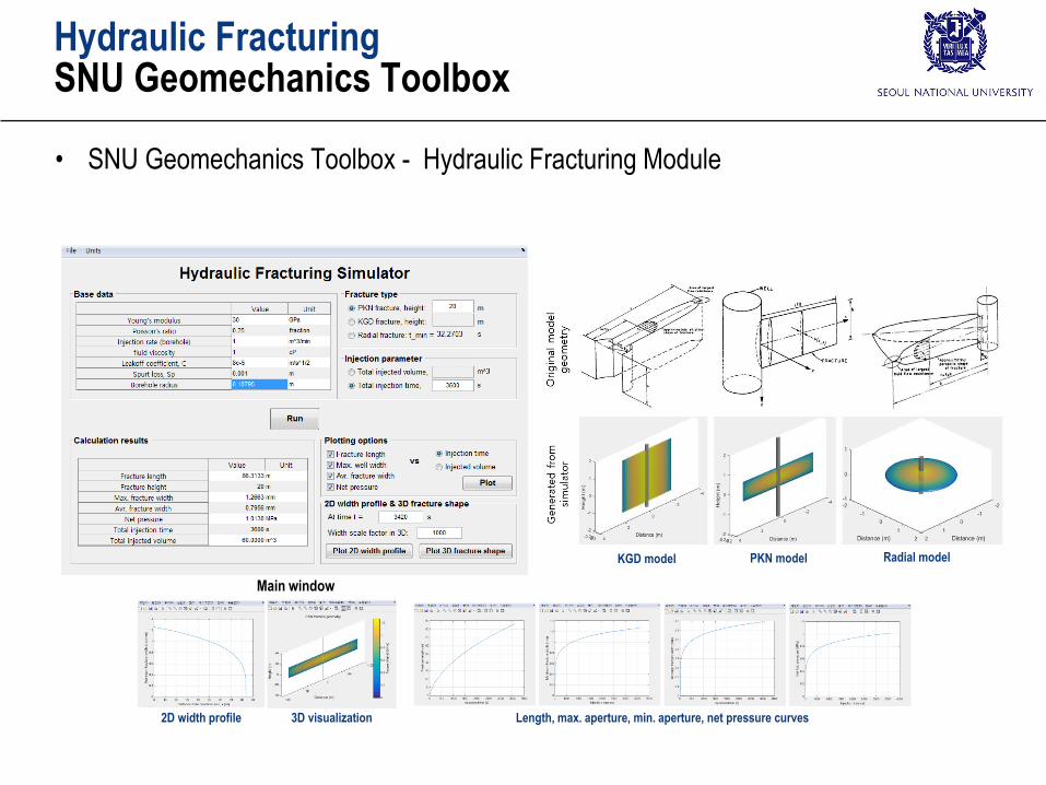
Main window
Length, max. aperture, min. aperture, net pressure curves2D width profile 3D visualization
KGD model PKN model Radial model
Hydraulic FracturingSNU Geomechanics Toolbox
• SNU Geomechanics Toolbox - Hydraulic Fracturing Module
Hydraulic FracturingSNU Geomechanics Toolbox
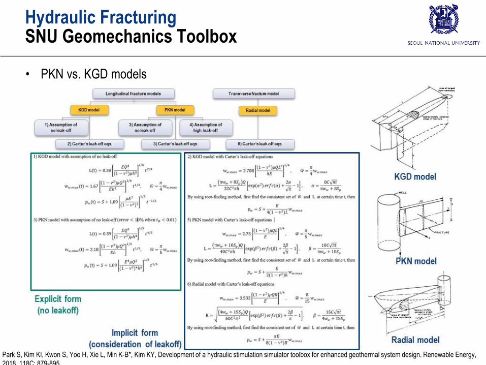
• PKN vs. KGD models
Park S, Kim KI, Kwon S, Yoo H, Xie L, Min K-B*, Kim KY, Development of a hydraulic stimulation simulator toolbox for enhanced geothermal system design. Renewable Energy,
2018, 118C: 879-895
Hydraulic FracturingProppant
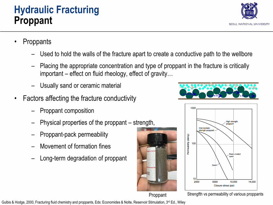
• Proppants
– Used to hold the walls of the fracture apart to create a conductive path to the wellbore
– Placing the appropriate concentration and type of proppant in the fracture is critically important – effect on fluid rheology, effect of gravity…
– Usually sand or ceramic material
• Factors affecting the fracture conductivity
– Proppant composition
– Physical properties of the proppant – strength,
– Proppant-pack permeability
– Movement of formation fines
– Long-term degradation of proppant
Strengfth vs permeability of various proppants
Gulbis & Hodge, 2000, Fracturing fluid chemistry and proppants, Eds: Economides & Nolte, Reservoir Stimulation, 3rd Ed., Wiley
Proppant
Hydraulic FracturingShear stimulation (Hydraulic shearing)
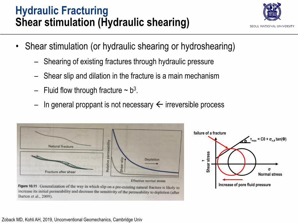
• Shear stimulation (or hydraulic shearing or hydroshearing)
– Shearing of existing fractures through hydraulic pressure
– Shear slip and dilation in the fracture is a main mechanism
– Fluid flow through fracture ~ b3.
– In general proppant is not necessary irreversible process
Increase of pore fluid pressure
σ
Normal stress
τmax = C0 + σn,θ tan(Φ)
failure of a fracture
Φ
τ
Sh
ear
stre
ss
Zoback MD, Kohli AH, 2019, Unconventional Geomechanics, Cambridge Univ
Hydraulic FracturingShear stimulation (Hydraulic shearing)
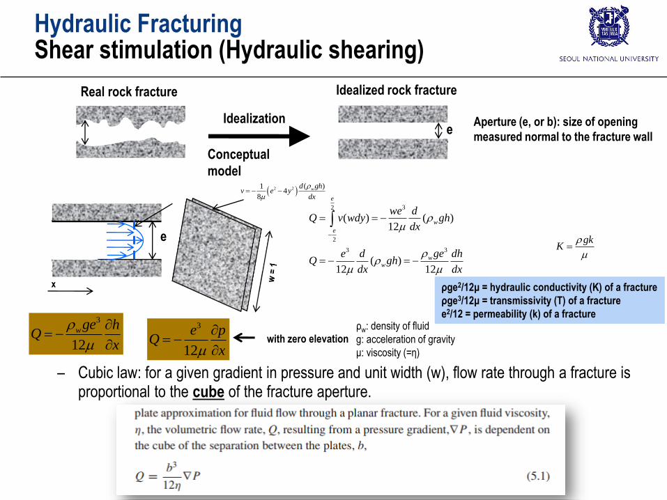
e
Real rock fracture Idealized rock fracture
Idealization
Conceptual
model
Aperture (e, or b): size of opening
measured normal to the fracture wall
– Cubic law: for a given gradient in pressure and unit width (w), flow rate through a fracture is proportional to the cube of the fracture aperture.
e
x
3
12
wge hQ
x
3
12
e pQ
x
with zero elevation
ρw: density of fluid
g: acceleration of gravity
μ: viscosity (=η)
32
2
33
( ) ( )12
( )12 12
e
w
e
ww
we dQ v wdy gh
dx
gee d dhQ gh
dx dx
2 2 ( )14
8
wd ghv e y
dx
ρge2/12μ = hydraulic conductivity (K) of a fracture
ρge3/12μ = transmissivity (T) of a fracture
e2/12 = permeability (k) of a fracture
gkK

Hydraulic FracturingShear stimulation (Hydraulic shearing)
• Shear dilation observation (Olsson & Barton, 2001)
Olsson, R. and N. Barton (2001). "An improved model for hydromechanical coupling during shearing of rock joints." International Journal of Rock Mechanics and
Mining Sciences 38(3): 317-329.
Shear dilation
Rothert E & Baisch S, 2010, Passive Seismic Monitoring: Mapping Enhanced Fracture Permeability, 10th World Geothermal Congress, Paper No.3161
Rothert & Baisch (2010)
tran
smis
sivi
ty (
T)
of
a fr
actu
re =
ρg
e3 /12
μ
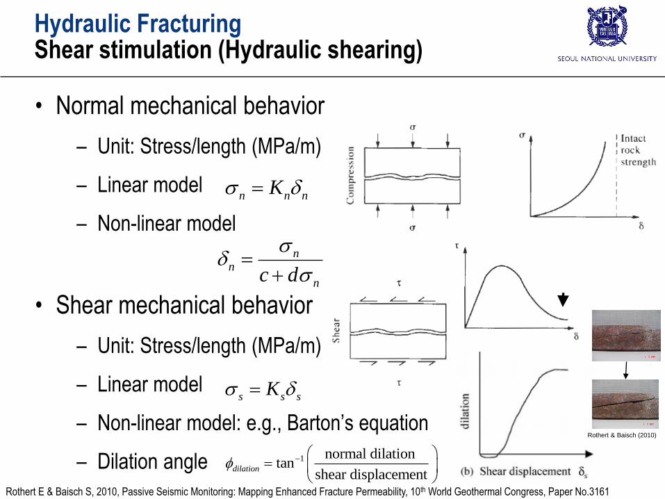
• Normal mechanical behavior
– Unit: Stress/length (MPa/m)
– Linear model
– Non-linear model
• Shear mechanical behavior
– Unit: Stress/length (MPa/m)
– Linear model
– Non-linear model: e.g., Barton’s equation
– Dilation angle
Hydraulic FracturingShear stimulation (Hydraulic shearing)
nn
nc d
s s sK
n n nK
1 normal dilationtan
shear displacementdilation
Rothert & Baisch (2010)
Rothert E & Baisch S, 2010, Passive Seismic Monitoring: Mapping Enhanced Fracture Permeability, 10th World Geothermal Congress, Paper No.3161
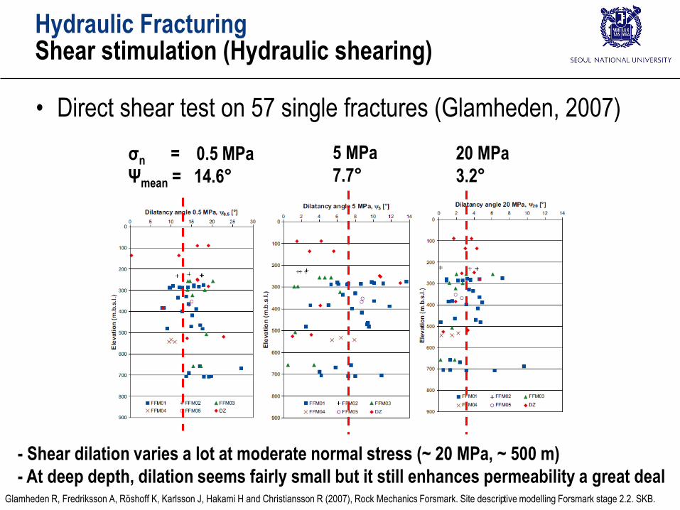
• Direct shear test on 57 single fractures (Glamheden, 2007)
Hydraulic FracturingShear stimulation (Hydraulic shearing)
σn = 0.5 MPa
Ψmean = 14.6°
5 MPa
7.7°
20 MPa
3.2°
Glamheden R, Fredriksson A, Röshoff K, Karlsson J, Hakami H and Christiansson R (2007), Rock Mechanics Forsmark. Site descriptive modelling Forsmark stage 2.2. SKB.
- Shear dilation varies a lot at moderate normal stress (~ 20 MPa, ~ 500 m)
- At deep depth, dilation seems fairly small but it still enhances permeability a great deal
Hydraulic FracturingShear stimulation (Hydraulic shearing)
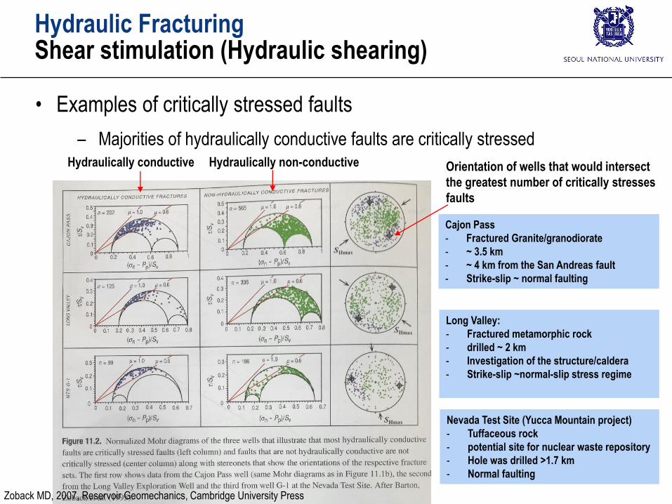
• Examples of critically stressed faults
– Majorities of hydraulically conductive faults are critically stressed
Long Valley:
- Fractured metamorphic rock
- drilled ~ 2 km
- Investigation of the structure/caldera
- Strike-slip ~normal-slip stress regime
Cajon Pass
- Fractured Granite/granodiorate
- ~ 3.5 km
- ~ 4 km from the San Andreas fault
- Strike-slip ~ normal faulting
Nevada Test Site (Yucca Mountain project)
- Tuffaceous rock
- potential site for nuclear waste repository
- Hole was drilled >1.7 km
- Normal faulting
Hydraulically conductive Hydraulically non-conductive Orientation of wells that would intersect
the greatest number of critically stresses
faults
Zoback MD, 2007, Reservoir Geomechanics, Cambridge University Press
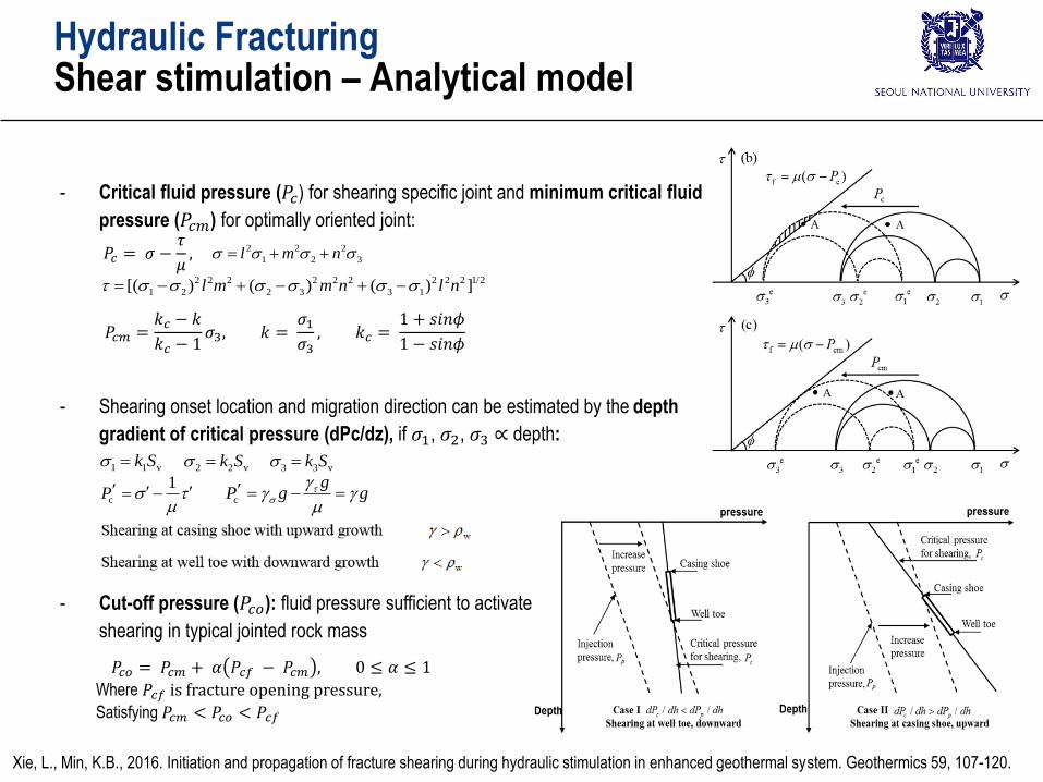
- Critical fluid pressure (𝑃𝑐) for shearing specific joint and minimum critical fluid
pressure (𝑃𝑐𝑚) for optimally oriented joint:
- Shearing onset location and migration direction can be estimated by the depth
gradient of critical pressure (dPc/dz), if 𝜎1, 𝜎2, 𝜎3 ∝ depth:
𝑃𝑐𝑚 =𝑘𝑐 − 𝑘
𝑘𝑐 − 1𝜎3, 𝑘 =
𝜎1𝜎3
, 𝑘𝑐 =1 + 𝑠𝑖𝑛𝜙
1 − 𝑠𝑖𝑛𝜙
𝑃𝑐 = 𝜎 −𝜏
𝜇, 2 2 2
1 2 3l m n
2 2 2 2 2 2 2 2 2 1/2
1 2 2 3 3 1[( ) ( ) ( ) ]l m m n l n
1 1 vk S 2 2 vk S 3 3 vk S
c
1P
c
gP g g
- Cut-off pressure (𝑃𝑐𝑜): fluid pressure sufficient to activate
shearing in typical jointed rock mass
𝑃𝑐𝑜 = 𝑃𝑐𝑚 + 𝛼 𝑃𝑐𝑓 − 𝑃𝑐𝑚 , 0 ≤ 𝛼 ≤ 1
Where 𝑃𝑐𝑓 is fracture opening pressure,
Satisfying 𝑃𝑐𝑚 < 𝑃𝑐𝑜 < 𝑃𝑐𝑓
Xie, L., Min, K.B., 2016. Initiation and propagation of fracture shearing during hydraulic stimulation in enhanced geothermal system. Geothermics 59, 107-120.
Hydraulic FracturingShear stimulation – Analytical model
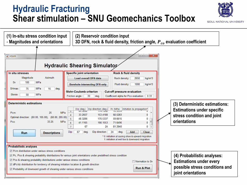
(2) Reservoir condition input
3D DFN, rock & fluid density, friction angle, 𝑷𝒄𝒐 evaluation coefficient
(3) Deterministic estimations:
Estimations under specific
stress condition and joint
orientations
(4) Probabilistic analyses:
Estimations under every
possible stress conditions and
joint orientations
(1) In-situ stress condition input
- Magnitudes and orientations
Hydraulic FracturingShear stimulation – SNU Geomechanics Toolbox
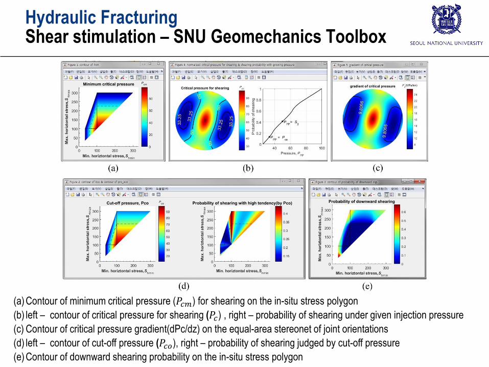
(a) Contour of minimum critical pressure (𝑃𝑐𝑚) for shearing on the in-situ stress polygon
(b) left – contour of critical pressure for shearing (𝑃𝑐) , right – probability of shearing under given injection pressure
(c) Contour of critical pressure gradient(dPc/dz) on the equal-area stereonet of joint orientations
(d) left – contour of cut-off pressure (𝑃𝑐𝑜), right – probability of shearing judged by cut-off pressure
(e) Contour of downward shearing probability on the in-situ stress polygon
Hydraulic FracturingShear stimulation – SNU Geomechanics Toolbox
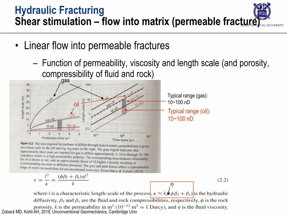
Hydraulic FracturingShear stimulation – flow into matrix (permeable fracture)
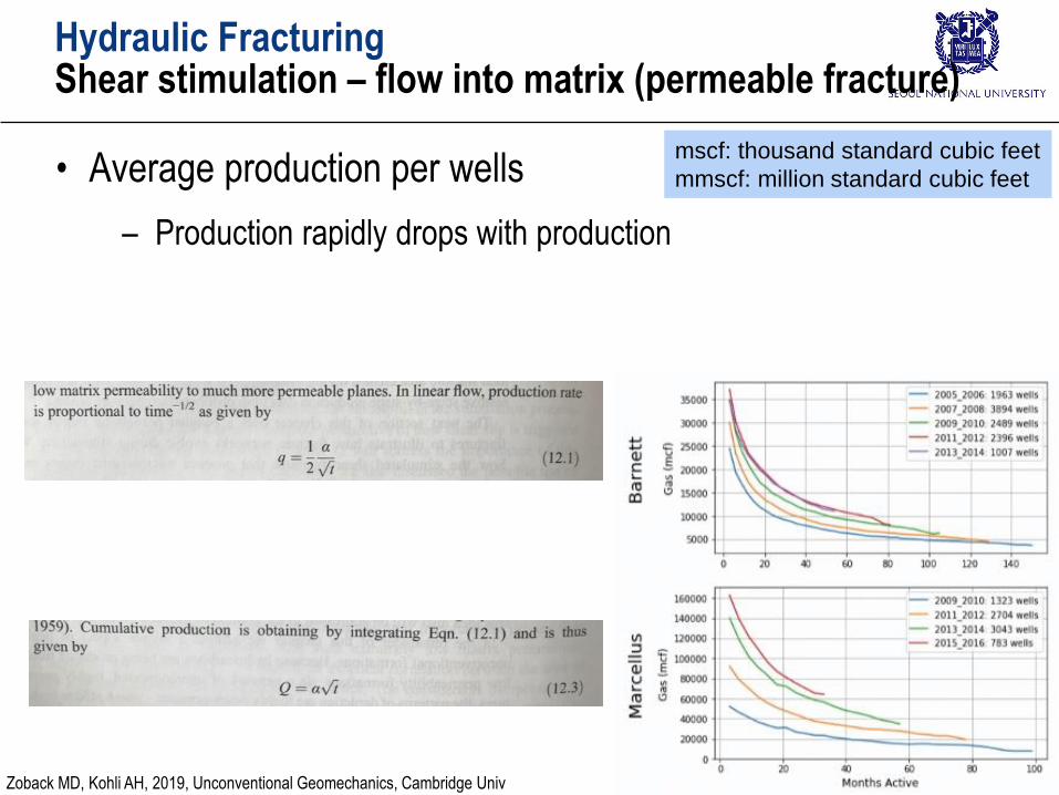
• Linear flow into permeable fractures
– Function of permeability, viscosity and length scale (and porosity, compressibility of fluid and rock)
gas
oilTypical range (oil):
10~100 nD
Typical range (gas):
10~100 nD
Zoback MD, Kohli AH, 2019, Unconventional Geomechanics, Cambridge Univ
Hydraulic FracturingShear stimulation – flow into matrix (permeable fracture)
• Average production per wells
– Production rapidly drops with production
mscf: thousand standard cubic feet
mmscf: million standard cubic feet
Zoback MD, Kohli AH, 2019, Unconventional Geomechanics, Cambridge Univ
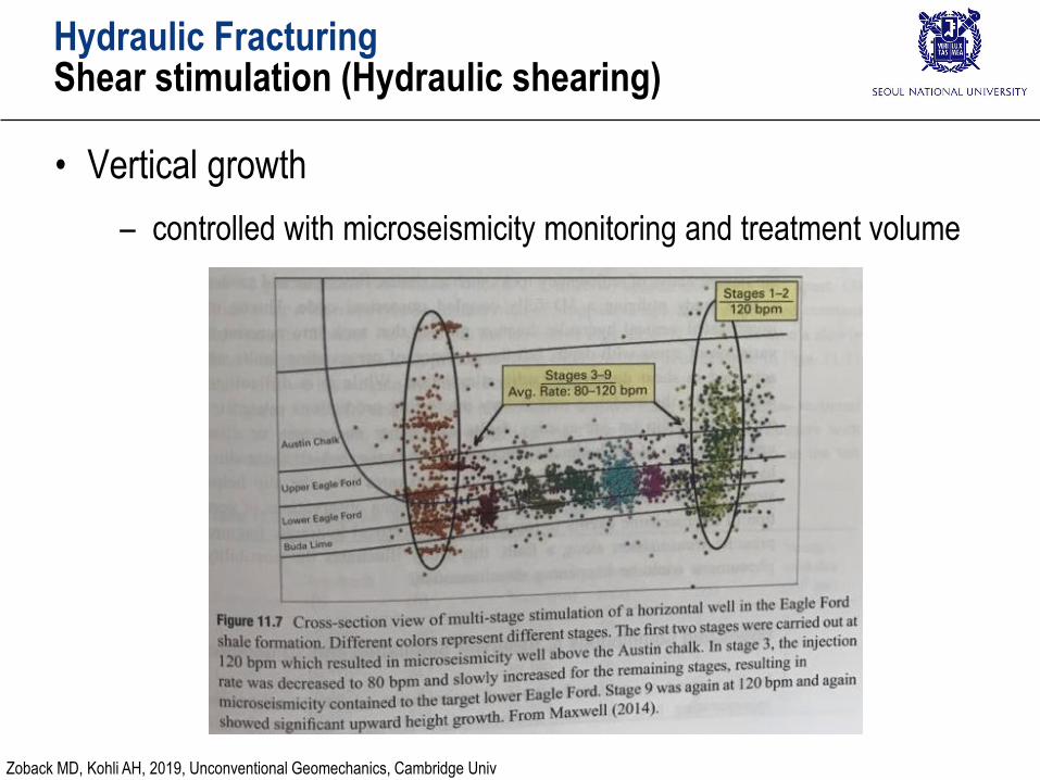
Hydraulic FracturingShear stimulation (Hydraulic shearing)
• Vertical growth
– controlled with microseismicity monitoring and treatment volume
Zoback MD, Kohli AH, 2019, Unconventional Geomechanics, Cambridge Univ
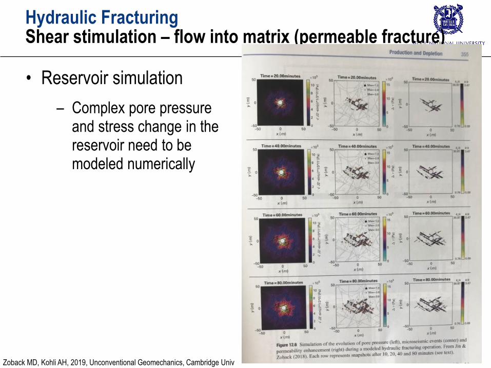
Hydraulic FracturingShear stimulation – flow into matrix (permeable fracture)
• Reservoir simulation
– Complex pore pressure and stress change in the reservoir need to be modeled numerically
Zoback MD, Kohli AH, 2019, Unconventional Geomechanics, Cambridge Univ
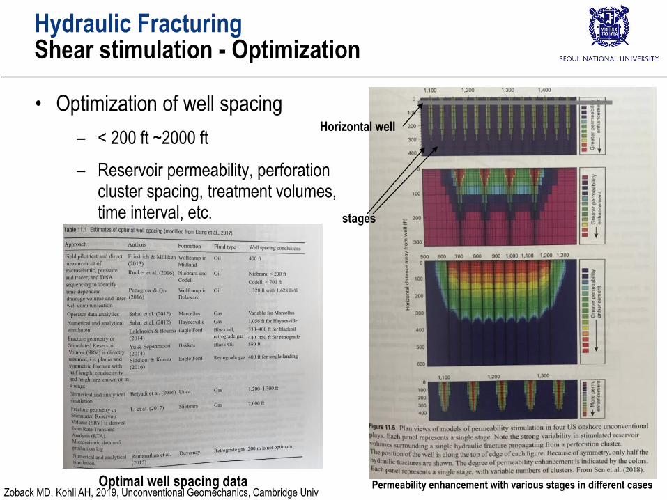
Hydraulic FracturingShear stimulation - Optimization
• Optimization of well spacing
– < 200 ft ~2000 ft
– Reservoir permeability, perforation cluster spacing, treatment volumes, time interval, etc.
Horizontal well
stages
Optimal well spacing data Permeability enhancement with various stages in different casesZoback MD, Kohli AH, 2019, Unconventional Geomechanics, Cambridge Univ
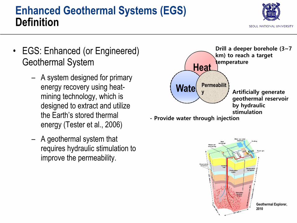
Heat
물 Permeability
Drill a deeper borehole (3~7 km) to reach a target temperature
Artificially generate geothermal reservoir by hydraulic stimulation
- Provide water through injection
Water Permeabilit
y
Enhanced Geothermal Systems (EGS)Definition
Geothermal Explorer,
2010
• EGS: Enhanced (or Engineered) Geothermal System
– A system designed for primary energy recovery using heat-mining technology, which is designed to extract and utilize the Earth’s stored thermal energy (Tester et al., 2006)
– A geothermal system that requires hydraulic stimulation to improve the permeability.
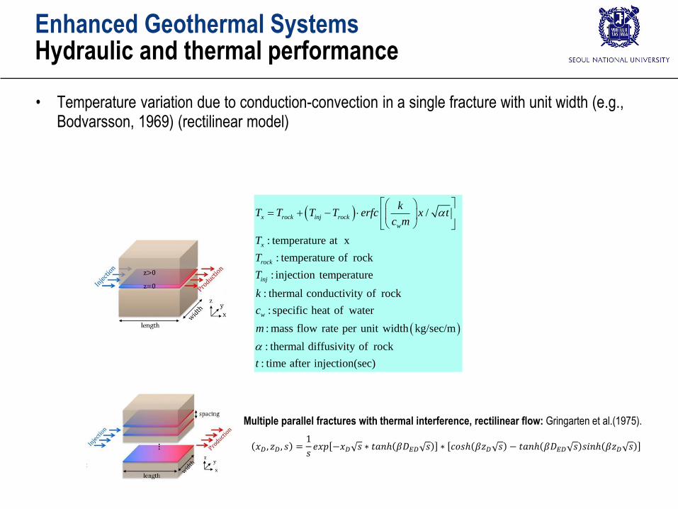
Enhanced Geothermal SystemsHydraulic and thermal performance
• Temperature variation due to conduction-convection in a single fracture with unit width (e.g., Bodvarsson, 1969) (rectilinear model)
/
: temperature at x
: temperature of rock
: injection temperature
: thermal conductivity of rock
: specific heat of water
: mass flow rate per unit width kg/sec/m
: therma
x rock inj rock
w
x
rock
inj
w
kT T T T erfc x t
c m
T
T
T
k
c
m
l diffusivity of rock
: time after injection(sec)t
Multiple parallel fractures with thermal interference, rectilinear flow: Gringarten et al.(1975).
𝑥𝐷 , 𝑧𝐷, 𝑠 =1
𝑠𝑒𝑥𝑝 −𝑥𝐷 𝑠 ∗ 𝑡𝑎𝑛ℎ 𝛽𝐷𝐸𝐷 𝑠 ∗ 𝑐𝑜𝑠ℎ 𝛽𝑧𝐷 𝑠 − 𝑡𝑎𝑛ℎ 𝛽𝐷𝐸𝐷 𝑠 𝑠𝑖𝑛ℎ 𝛽𝑧𝐷 𝑠
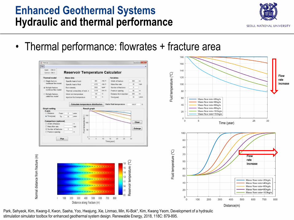
Res
ervo
ir te
mpe
ratu
re(℃
)
Nor
mal
dis
tanc
e fr
om fr
actu
re(m
)
Time (year)
Flu
id te
mpe
ratu
re(℃
)
Distance(m)
Flu
id te
mpe
ratu
re(℃
)
Enhanced Geothermal SystemsHydraulic and thermal performance
Flow
rate
increase
Flow
rate
increase
Park, Sehyeok, Kim, Kwang-Il, Kwon, Saeha, Yoo, Hwajung, Xie, Linmao, Min, Ki-Bok*, Kim, Kwang Yeom, Development of a hydraulic
stimulation simulator toolbox for enhanced geothermal system design. Renewable Energy, 2018, 118C: 879-895.
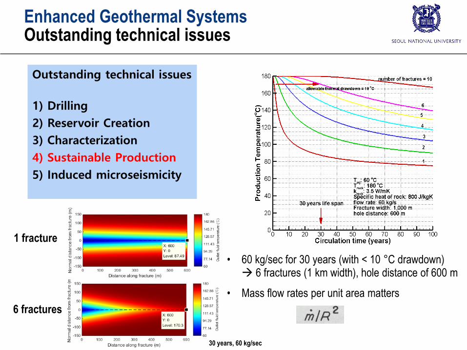
• Thermal performance: flowrates + fracture area
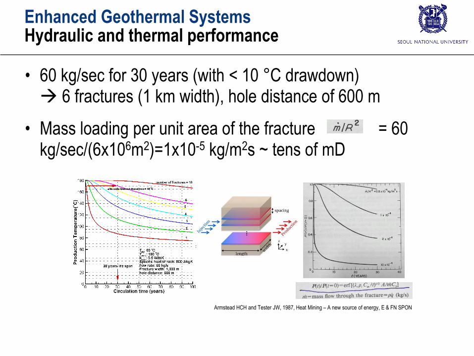
Enhanced Geothermal SystemsHydraulic and thermal performance
• 60 kg/sec for 30 years (with < 10 °C drawdown) 6 fractures (1 km width), hole distance of 600 m
• Mass loading per unit area of the fracture = 60 kg/sec/(6x106m2)=1x10-5 kg/m2s ~ tens of mD
Armstead HCH and Tester JW, 1987, Heat Mining – A new source of energy, E & FN SPON
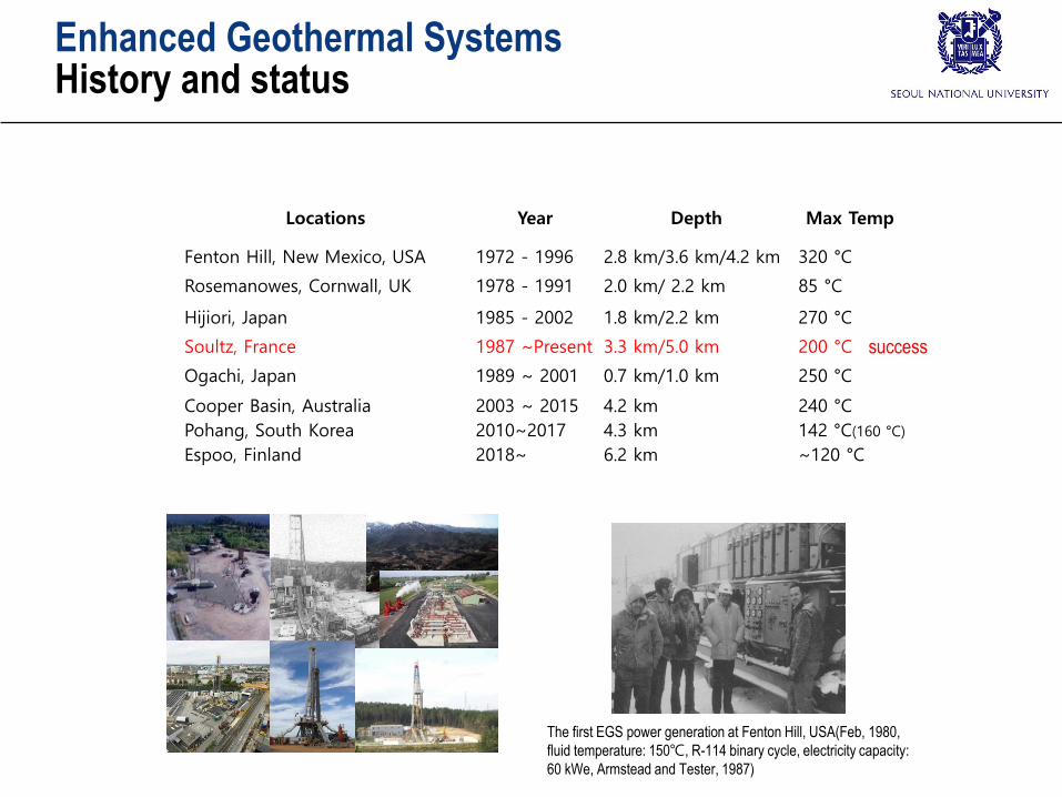
Enhanced Geothermal SystemsHistory and status
Locations Year Depth Max Temp
Fenton Hill, New Mexico, USA 1972 - 1996 2.8 km/3.6 km/4.2 km 320 °C
Rosemanowes, Cornwall, UK 1978 - 1991 2.0 km/ 2.2 km 85 °C
Hijiori, Japan 1985 - 2002 1.8 km/2.2 km 270 °C
Soultz, France 1987 ~Present 3.3 km/5.0 km 200 °C
Ogachi, Japan 1989 ~ 2001 0.7 km/1.0 km 250 °C
Cooper Basin, Australia
Pohang, South Korea
Espoo, Finland
2003 ~ 2015
2010~2017
2018~
4.2 km
4.3 km
6.2 km
240 °C
142 °C(160 °C)
~120 °C
The first EGS power generation at Fenton Hill, USA(Feb, 1980,
fluid temperature: 150℃, R-114 binary cycle, electricity capacity:
60 kWe, Armstead and Tester, 1987)
success
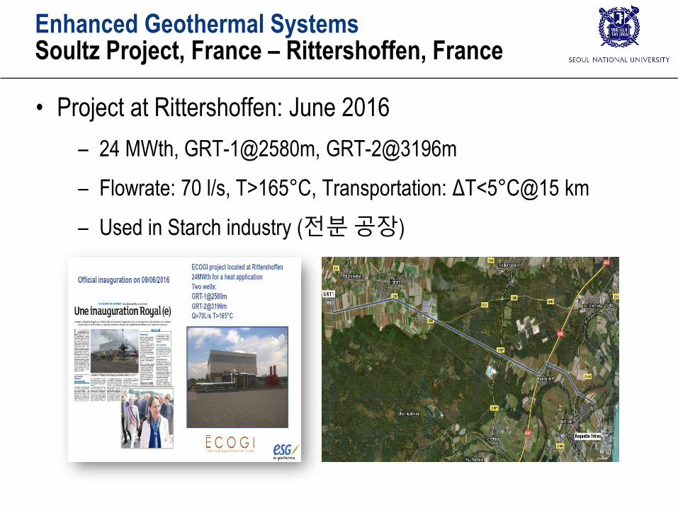
Enhanced Geothermal SystemsSoultz Project, France – Rittershoffen, France
• Project at Rittershoffen: June 2016
– 24 MWth, GRT-1@2580m, GRT-2@3196m
– Flowrate: 70 l/s, T>165°C, Transportation: ΔT<5°C@15 km
– Used in Starch industry (전분공장)
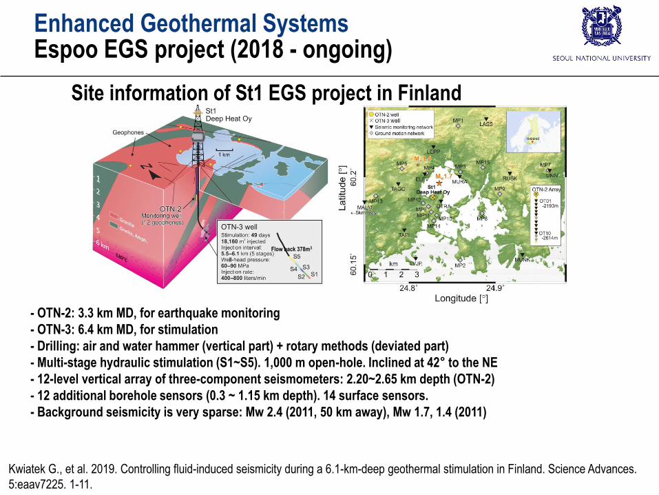
Site information of St1 EGS project in Finland
- OTN-2: 3.3 km MD, for earthquake monitoring
- OTN-3: 6.4 km MD, for stimulation
- Drilling: air and water hammer (vertical part) + rotary methods (deviated part)
- Multi-stage hydraulic stimulation (S1~S5). 1,000 m open-hole. Inclined at 42° to the NE
- 12-level vertical array of three-component seismometers: 2.20~2.65 km depth (OTN-2)
- 12 additional borehole sensors (0.3 ~ 1.15 km depth). 14 surface sensors.
- Background seismicity is very sparse: Mw 2.4 (2011, 50 km away), Mw 1.7, 1.4 (2011)
Kwiatek G., et al. 2019. Controlling fluid-induced seismicity during a 6.1-km-deep geothermal stimulation in Finland. Science Advances.
5:eaav7225. 1-11.
Flow back 378m3
Enhanced Geothermal SystemsEspoo EGS project (2018 - ongoing)
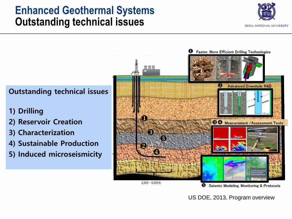
Enhanced Geothermal SystemsOutstanding technical issues
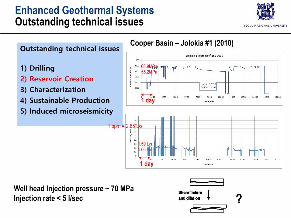
Outstanding technical issues
1) Drilling
2) Reservoir Creation
3) Characterization
4) Sustainable Production
5) Induced microseismicity
US DOE, 2013, Program overview

Enhanced Geothermal SystemsOutstanding technical issues
Outstanding technical issues
1) Drilling
2) Reservoir Creation
3) Characterization
4) Sustainable Production
5) Induced microseismicity
(MIT, 2006)
Enhanced Geothermal SystemsOutstanding technical issues
Outstanding technical issues
1) Drilling
2) Reservoir Creation
3) Characterization
4) Sustainable Production
5) Induced microseismicity
1 day
1 day
1 bpm = 2.65 L/s
1.06 L/s1.59 L/s
68.9MPa55.2MPa
Well head Injection pressure ~ 70 MPa
Injection rate < 5 l/sec
Cooper Basin – Jolokia #1 (2010)
?

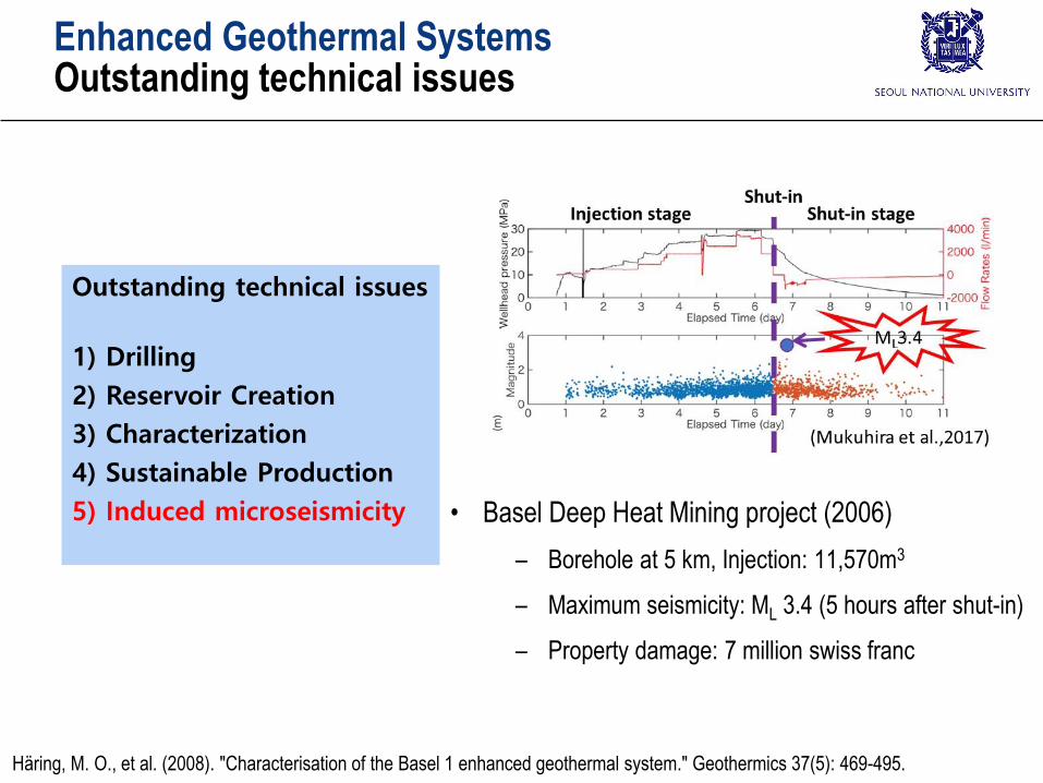
Enhanced Geothermal SystemsOutstanding technical issues
Outstanding technical issues
1) Drilling
2) Reservoir Creation
3) Characterization
4) Sustainable Production
5) Induced microseismicity
Borehole breakout at GPK1 @3450 m - Observed one
year after drilling (Cornet et al., 2007)170/350
Cornet, F. H., Th Bérard, and S. Bourouis. How Close to Failure Is a Granite Rock Mass at a 5 km
Depth?. Int J Rock Mech Min 44(1) (2007): 47-66.
Enhanced Geothermal SystemsOutstanding technical issues
Outstanding technical issues
1) Drilling
2) Reservoir Creation
3) Characterization
4) Sustainable Production
5) Induced microseismicity
• 60 kg/sec for 30 years (with < 10 °C drawdown) 6 fractures (1 km width), hole distance of 600 m
• Mass flow rates per unit area matters
1 fracture
6 fractures
30 years, 60 kg/sec
Enhanced Geothermal SystemsOutstanding technical issues
Outstanding technical issues
1) Drilling
2) Reservoir Creation
3) Characterization
4) Sustainable Production
5) Induced microseismicity • Basel Deep Heat Mining project (2006)
– Borehole at 5 km, Injection: 11,570m3
– Maximum seismicity: ML 3.4 (5 hours after shut-in)
– Property damage: 7 million swiss franc
Häring, M. O., et al. (2008). "Characterisation of the Basel 1 enhanced geothermal system." Geothermics 37(5): 469-495.
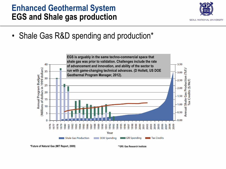
Enhanced Geothermal SystemEGS and Shale gas production
• Shale Gas R&D spending and production*
**GRI: Gas Research Institute*Future of Natural Gas (MIT Report, 2009)
EGS is arguably in the same techno-commercial space that
shale gas was prior to validation. Challenges include the rate
of advancement and innovation, and ability of the sector to
run with game-changing technical advances. (D Hollett, US DOE
Geothermal Program Manager, 2012).