lecture 15: addressing and routing architectureshervin/courses/ceg4185/lectures/...prof. shervin...
TRANSCRIPT
Prof. Shervin Shirmohammadi
CEG 4185
15-1
Lecture 15:
Addressing and Routing Architecture
Prof. Shervin Shirmohammadi
SITE, University of Ottawa
Prof. Shervin Shirmohammadi
CEG 4185
15-2
Addressing & Routing
•Addressingis assigning identifiersto devices.
These identifiers can be local or global, private or
public, temporary or persistent.
•Routingconsists of learning about the reachability
within and between networks and applying this
reachability to forward packets in the network.
•Together, they form a complete picture of network
connectivity.
Prof. Shervin Shirmohammadi
CEG 4185
15-3
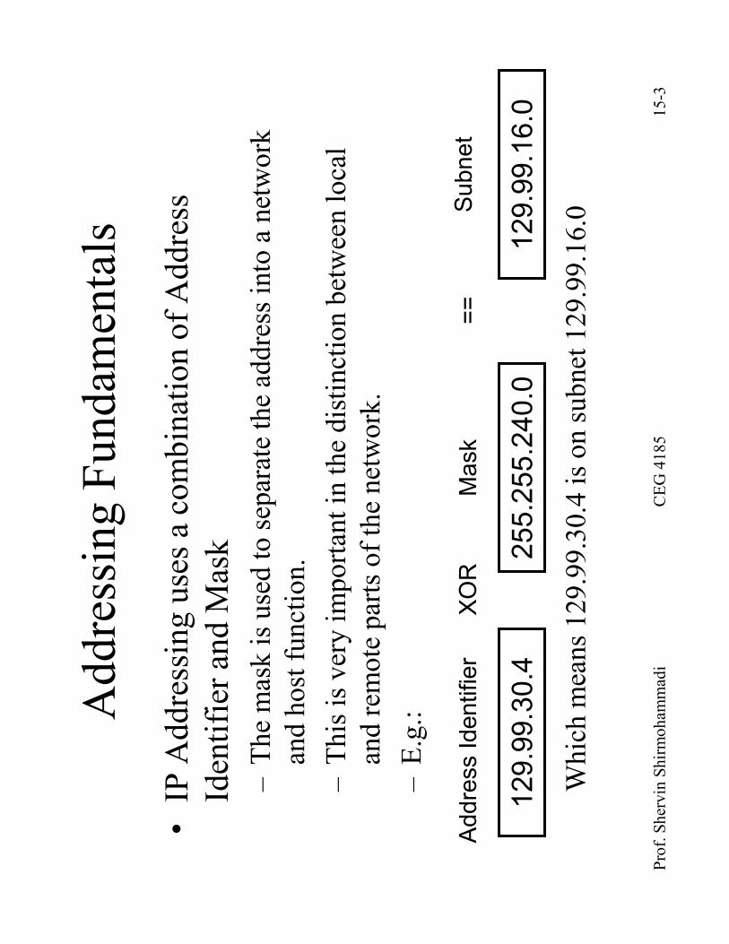
Addressing Fundamentals
•IP Addressing uses a combination of Address
Identifier and Mask
–The mask is used to separate the address into a network
and host function.
–This is very important in the distinction between local
and remote parts of the network.
–E.g.:
Which means 129.99.30.4 is on subnet 129.99.16.0
129.99.30.4
255.255.240.0
Address Identifier
Mask
XOR
==
129.99.16.0
Subnet
Prof. Shervin Shirmohammadi
CEG 4185
15-4
Type of Addresses
•Localor Global
–Local communication addresses like link-layer (MAC Address).
–Not advertised outside of the local network: there's no point since
there is no link-layer connectivity between non-local devices.
–Global addresses are required for devices outside of the local
broadcast region like IP addresses.
•Privateor Public
–Both are global addresses, but private addresses are not advertised
and forwarded (on purpose) while public addresses are.
•Temporaryof Persistent
–Temporary are usually assigned using DHCP while persistent
addresses are assigned either manually or are hardcoded (like
Ethernet address “carved”into an Ethernet network card.

Prof. Shervin Shirmohammadi
CEG 4185
15-5
Local vs. Remote Network
Network
.0.1
.0.2
.0.3
Other Network
136.178.0.1
129.99.0.100
136.178.0.100
Devices on the same subnet are
directly connected and therefore, for
IP, address resolution is done at
different layer (MAC) than that done at
the routing layer (IP).
In communicating to devices on
other networks there must be a
router connecting the networks
136.178.0.0/16
129.99.0.0/16
Prof. Shervin Shirmohammadi
CEG 4185
15-6
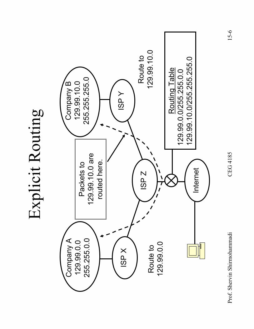
Explicit Routing
Company A
129.99.0.0
255.255.0.0
Company B
129.99.10.0
255.255.255.0
ISP X
ISP Y
ISP Z
Routing Table
129.99.0.0/255.255.0.0
129.99.10.0/255.255.255.0
Internet
Route to
129.99.0.0
Route to
129.99.10.0
Packets to
129.99.10.0 are
routed here.
Prof. Shervin Shirmohammadi
CEG 4185
15-7
Addressing Mechanisms
•Classfuladdressing
–older style of addressing
•Subnetting
–A better way to distribute addresses
•Variable-length subnetting
–Even more refined than subnetting
•Supernettingand Classless interdomainrouting (CIDR).
–An efficient way to advertise addresses, and currently used on
the Internet.
•Private addressingand Network Address Translation
(NAT).
–A way to re-use certain IP addresses without collision with
the rest of Internet
Prof. Shervin Shirmohammadi
CEG 4185
15-8
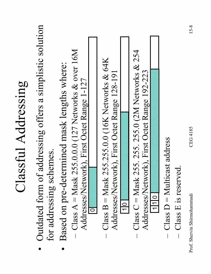
ClassfulAddressing
•Outdated form of addressing offers a simplistic solution
for addressing schemes.
•Based on pre-determined mask lengths where:
–Class A = Mask 255.0.0.0 (127 Networks & over 16M
Addresses/Network), First Octet Range 1-127
–Class B = Mask 255.255.0.0 (16K Networks & 64K
Addresses/Network), First Octet Range 128-191
–Class C = Mask 255. 255. 255.0 (2M Networks & 254
Addresses/Network), First Octet Range 192-223
–Class D = Multicast address
–Class E is reserved.
0 10
110
Prof. Shervin Shirmohammadi
CEG 4185
15-9
Limits to ClassfulAddressing
•Very few
Class A and B addresses, and all have
already been allocated.
–That leaves class C to allocate new addresses
•Many networks require more addressesthan
class C but fewer addressesthan B offers.
–On the other hand many organizations with A or B
cannot use all of the networks offered by class A or
B.
•That has led to variable-length subnets
Prof. Shervin Shirmohammadi
CEG 4185
15-10
Subnetting
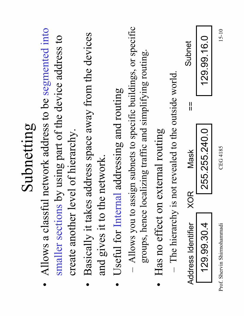
•Allows a classfulnetwork address to be segmented into
smaller sectionsby using part of the device address to
create another level of hierarchy.
•Basically it takes address space away from the devices
and gives it to the network.
•Useful forInternaladdressing and routing
–Allows you to assign subnets to specific buildings, or specific
groups, hence localizing traffic and simplifying routing.
•Has no effect on external routing
–The hierarchy is not revealed to the outside world.
129.99.30.4
255.255.240.0
Address Identifier
Mask
XOR
==
129.99.16.0
Subnet

Prof. Shervin Shirmohammadi
CEG 4185
15-11
Subnettingfor Class B Network
2-Bit Mask
255.255.192.0
3-Bit Mask
255.255.224.0
4-Bit Mask
255.255.240. 0
5-Bit Mask
255.255.248. 0
6-Bit Mask
255.255.252. 0
7-Bit Mask
255.255.254. 0
8-Bit Mask
255.255.255. 0
Class B
255.255.0.0
1 Network
64K Devices
3 Subnets
16382 Devices/Subnet
7 Subnets
8190 Devices/Subnet
15 Subnets
4094 Devices/Subnet
31 Subnets
2046 Devices/Subnet
63 Subnets
1022 Devices/Subnet
127 Subnets
510 Devices/Subnet
255 Subnets
254 Devices/Subnet
Notice that all zerosare not allowed as either subnet part or as host
part. Also, all onesare not allowed for the host part.
Prof. Shervin Shirmohammadi
CEG 4185
15-12
Example
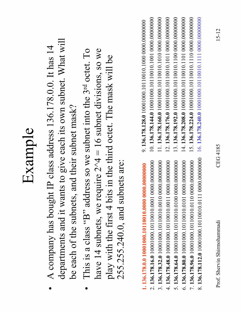
•A company has bought IP class address 136.178.0.0. It has 14
departments and it wants to give each its own subnet. What will
be each of the subnets, and their subnet mask?
•This is a class “B”address so we subnet into the 3rdoctet. To
have 14 subnets, we require 2^4 = 16 subnet divisions, so we
play with the first 4 bits in the third octet. The mask will be
255.255.240.0, and subnets are:
1. 136.1
78.0
.0 1
0001000.1
0110010.0
000 0
000.0
0000000
2. 136.1
78.1
6.010001000.10110010.0001 0000.00000000
3. 136.1
78.3
2.010001000.10110010.0010 0000.00000000
4.136.1
78.4
8.010001000.10110010.0011 0000.00000000
5. 136.1
78.6
4.010001000.10110010.0100 0000.00000000
6. 136.1
78.8
0.010001000.10110010.0101 0000.00000000
7. 136.1
78.9
6.010001000.10110010.0110 0000.00000000
8. 136.1
78.1
12.010001000.10110010.0111 0000.00000000
9. 136.1
78.1
28.010001000.10110010.1000 0000.00000000
10. 136.1
78.1
44.010001000.10110010.1001 0000.00000000
11. 136.1
78.1
60.010001000.10110010.1010 0000.00000000
12. 136.1
78.1
76.010001000.10110010.1011 0000.00000000
13. 136.1
78.1
92.010001000.10110010.1100 0000.00000000
14. 136.1
78.2
08.010001000.10110010.1101 0000.00000000
15. 136.1
78.2
24.010001000.10110010.1110 0000.00000000
16. 136.1
78.2
40.010001000.10110010.1111 0000.00000000
Prof. Shervin Shirmohammadi
CEG 4185
15-13
Variable-length Subnetting
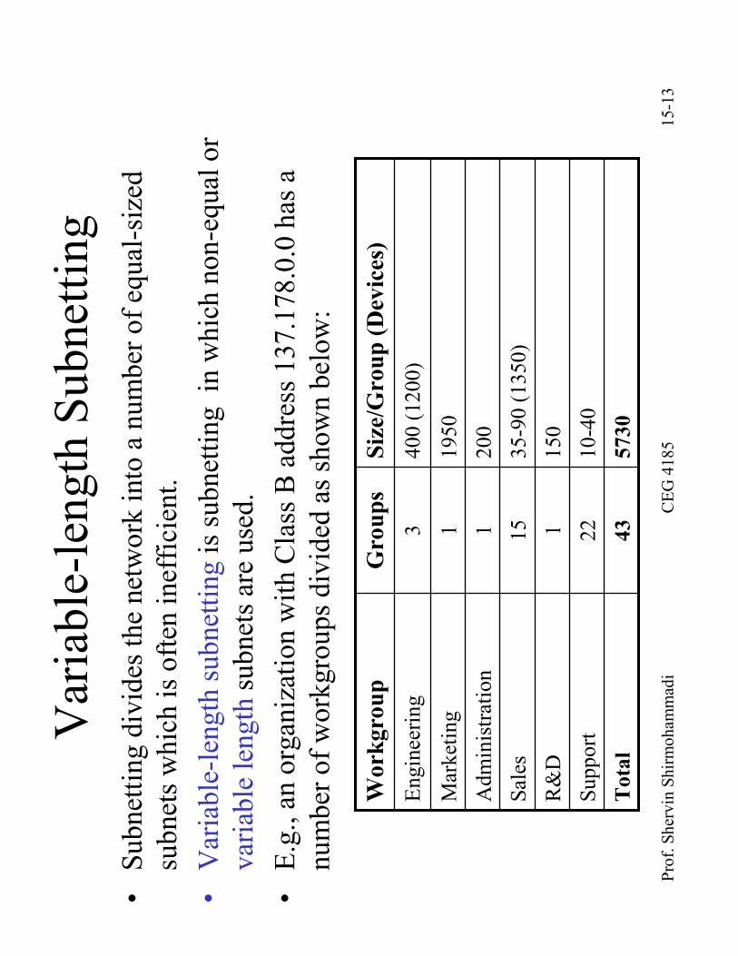
•Subnettingdivides the network into a number of equal-sized
subnets which is often inefficient.
•Variable-length subnettingis subnettingin which non-equal or
variable lengthsubnets are used.
•E.g., an organization with Class B address 137.178.0.0 has a
number of workgroups divided as shown below:
5730
43
Tota
l
10-40
22
Support
150
1R&D
35-90 (1350)
15
Sales
200
1Administration
1950
1Marketing
400 (1200)
3Engineering
Siz
e/G
roup (D
evic
es)
Gro
ups
Work
gro
up
Prof. Shervin Shirmohammadi
CEG 4185
15-14
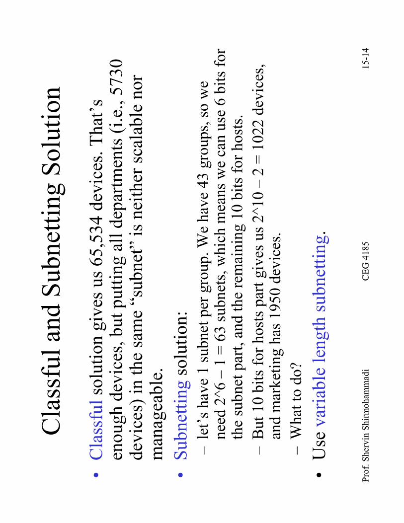
Classfuland SubnettingSolution
•Classfulsolution gives us 65,534 devices. That’s
enough devices, but putting all departments (i.e., 5730
devices) in the same “subnet”is neither scalable nor
manageable.
•Subnettingsolution:
–let’s have 1 subnet per group. We have 43 groups, so we
need 2^6 –1 = 63 subnets, which means we can use 6 bits for
the subnet part, and the remaining 10 bits for hosts.
–But 10 bits for hosts part gives us 2^10 –2 = 1022 devices,
and marketing has 1950 devices.
–What to do?
•Use variable length subnetting.
Prof. Shervin Shirmohammadi
CEG 4185
15-15
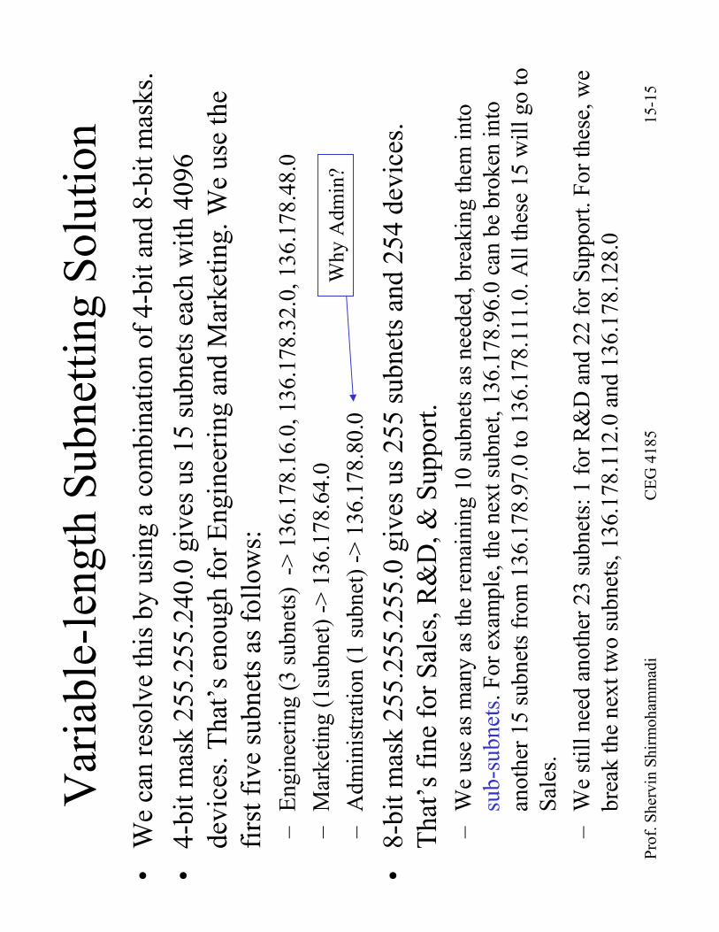
Variable-length SubnettingSolution
•We can resolve this by using a combination of 4-bit and 8-bit masks.
•4-bit mask 255.255.240.0 gives us 15 subnets each with 4096
devices. That’s enough for Engineering and Marketing. We use the
first five subnets as follows:
–Engineering (3 subnets) -> 136.178.16.0, 136.178.32.0, 136.178.48.0
–Marketing (1subnet) -> 136.178.64.0
–Administration (1 subnet) -> 136.178.80.0
•8-bit mask 255.255.255.0 gives us 255 subnets and 254 devices.
That’s fine for Sales, R&D, & Support.
–We use as many as the remaining 10 subnets as needed, breaking them into
sub-subnets. For example, the next subnet, 136.178.96.0 can be broken into
another 15 subnets from 136.178.97.0 to 136.178.111.0. All these15 will go to
Sales.
–We still need another 23 subnets: 1 for R&D and 22 for Support. For these, we
break the next two subnets, 136.178.112.0 and 136.178.128.0
Why Admin?
Prof. Shervin Shirmohammadi
CEG 4185
15-16
Supernetting
•Supernettingis the concept of aggregating network addresses by
changing the network mask to decrease the number of bits
recognized as the network part.
•Millions of Class C addresses can be allocated in lieu of Class
A & B.
–The result is that too many Class C address groups need to be allocated
to an organization and advertised among all the Internet routers.
–The number of routes would grow exponentially such that some
experts had predicted that the Internet would collapse by 1995.
–Obviously this did not happen, since supernettingwas invented.
•Say a company needs to support 10,000 devices.
–A class C address supports up to 254 devices, so 40 class C networks
are needed.
–How are we to advertise these 40 class C addresses?
Prof. Shervin Shirmohammadi
CEG 4185
15-17
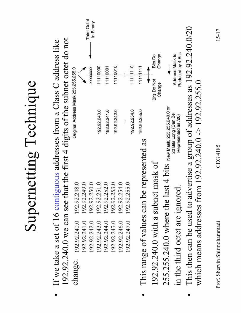
SupernettingTechnique
•If we take a set of 16 contiguousaddresses from a Class C address like
192.92.240.0 we can see that the first 4 digits of the subnet octet do not
change.
•This range of values can be represented as
192.92.240.0 with a subnet mask of
255.255.240.0 where the last 4 bits
in the third octet are ignored.
•This then can be used to advertise a group of addresses as 192.92.240.0/20
which means addresses from 192.92.240.0 -> 192.92.255.0

Prof. Shervin Shirmohammadi
CEG 4185
15-18
Classless InterDomainRouting (CIDR)
•The concept of supernettingsuggested that indeed we do not need class
boundaries, since each “group”can advertise its own subnet mask too.
•This in effect lead to classless ClasslessInterDomainRouting (CIDR).
•Addresses must be assigned in contiguousblocks following logical
topology.
•The number of addresses in a CIDR block are powers of 2.
•Network Prefix can be anything, and need not be a power of 2. Itis
transmitted along with address
•Used in conjunction with classless routing protocols (e. g. EIGRP, OSPF)
•E.g.:
–192.92.240/22 advertises 4 networks: 240, 241, 242, and 243
–192.92.240/23 advertises 2 networks: 240 and 241
–192.92.240/24 (this is the natural mask for class C) advertises 1 network: 240
–192.92.240/21 advertises 8 networks: 240 to 247
–200.1.128.0/17 is equivalent to a range of 27, or 128, networks from
200.1.128.0 -> 200.1.255.0
Prof. Shervin Shirmohammadi
CEG 4185
15-19
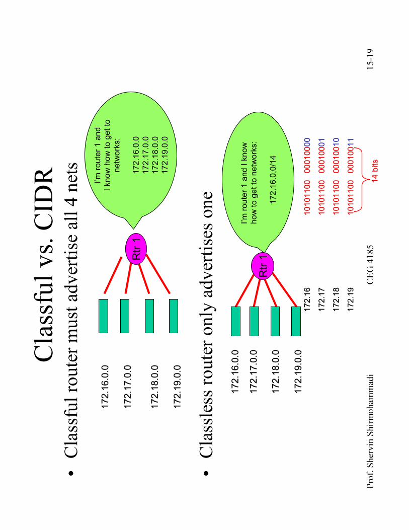
Classfulvs. CIDR
•Classfulrouter must advertise all 4 nets
•Classless router only advertises one
172.16.0.0
172.16.0.0
172.17.0.0
172.17.0.0
172.18.0.0
172.18.0.0
172.19.0.0
172.19.0.0
Rtr1
I’m router 1 and
I know how to get to
networks:
172.16.0.0
172.17.0.0
172.18.0.0
172.19.0.0
172.16.0.0
172.16.0.0
172.17.0.0
172.17.0.0
172.18.0.0
172.18.0.0
172.19.0.0
172.19.0.0
Rtr1
I’m router 1 and I know
how to get to networks:
172.16.0.0/14
172.16
172.16
10101100 000100
10101100 0001000000
172.17
172.17
10101100 000100
10101100 0001000101
172.18
172.18
10101100 000100
10101100 0001001010
172.19
172.19
10101100 000100
10101100 0001001111
14 bits
14 bits

Prof. Shervin Shirmohammadi
CEG 4185
15-20
Private Addresses and NATs
•Private IP Addressesare reserved addresses that can’t be
forwarded to the Internet
10.0.0.0 -> 10.255.255.255 (10/8 prefix)
172.16.0.0 -> 172.31.255.255 (172.16/12 prefix)
192.168.0.0 -> 192.168.255.255 (192.168/16 prefix)
•Pros:
–Makes changing ISP easier
–Increases security
•Cons:
–Outsourcing management may be difficult
–Mergers may require renumbering
•Network Address Translation: translates private addresses <->
public addresses
–A binding is created between the addresses that lasts a period of time.
•Can be implemented in Router, Firewall, or Specialized device.
Prof. Shervin Shirmohammadi
CEG 4185
15-21
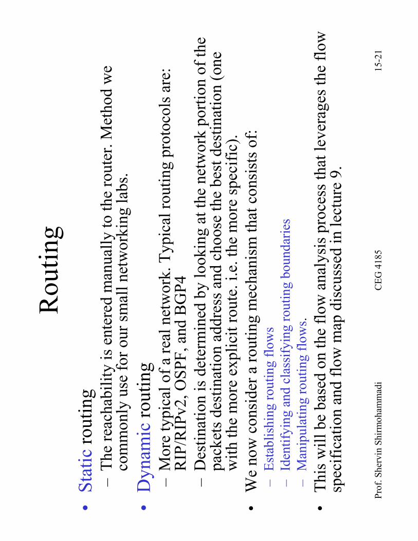
Routing
•Staticrouting
–The reachability is entered manually to the router. Method we
commonly use for our small networking labs.
•Dynamicrouting
–More typical of a real network. Typical routing protocols are:
RIP/RIPv2, OSPF, and BGP4
–Destination is determined by looking at the network portion of the
packets destination address and choose the best destination (one
with the more explicit route. i.e. the more specific).
•We now consider a routing mechanism that consists of:
–Establishing routing flows
–Identifying and classifying routing boundaries
–Manipulating routing flows .
•This will be based on the flow analysis process that leverages the flow
specification and flow map discussed in lecture 9.

Prof. Shervin Shirmohammadi
CEG 4185
15-22
Establishing Routing Flows
•Segment the network into functional areasand workgroups.
•Identify boundaries between these areas.
•Form relationships between boundaries and routing flows.
•A functional areaconsists of groups within the system that
share a similar function.
–These may consist of users (workgroups), applications, devices, or
combinations of these and they may share similar jobs, locations,
functions within the network (backbone routing).
•Workgroupsare groups of users that have common locations,
applications, and requirements, or that belong to the same
organization.
Prof. Shervin Shirmohammadi
CEG 4185
15-23
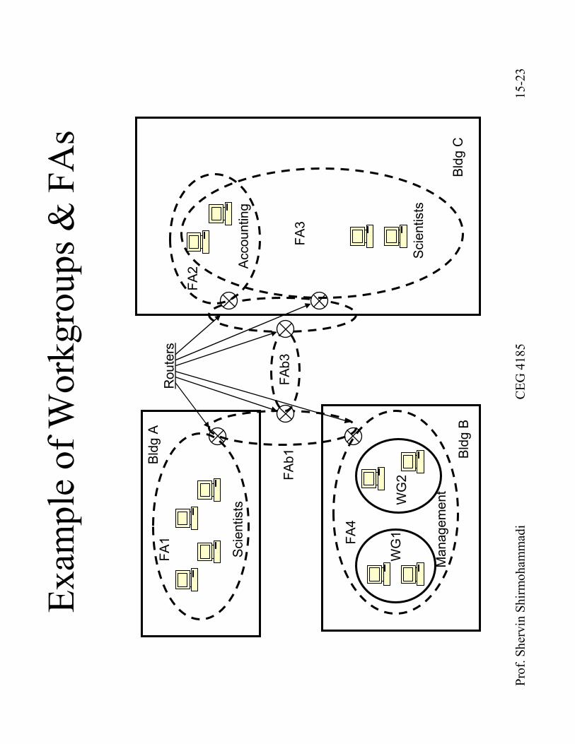
Example of Workgroups & FAs
Bldg A
Scientists
FA1
Bldg B
Management
FA4
WG1
WG2FAb1
FAb3
FA2
FA3
Scientists
Accounting
Bldg C
Routers
Prof. Shervin Shirmohammadi
CEG 4185
15-24
Routing Boundaries
•These are physical or logical separations of a network
based on requirements or administration of the
network.
•Physical Boundariescan de identified by isolated
LANs, DMZs, physical interfaces on network
equipment, physical security.
•Logical Boundariescan be identified by the FAs, WGs,
administrative domains (Autonomous Systems AS),
and routing management domains.
Prof. Shervin Shirmohammadi
CEG 4185
15-25
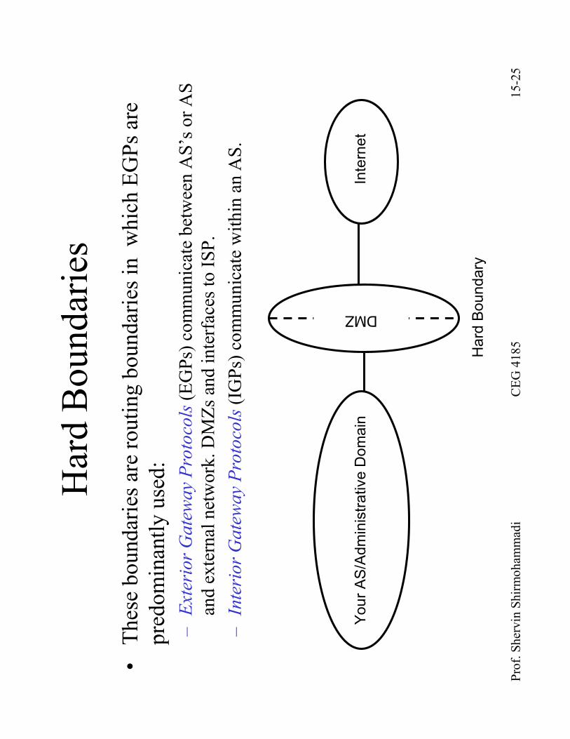
Hard Boundaries
•These boundaries are routing boundaries in which EGPsare
predominantly used:
–Exterior Gateway Protocols(EGPs) communicate between AS’s or AS
and external network. DMZsand interfaces to ISP.
–Interior Gateway Protocols(IGPs) communicate within an AS.
Your AS/Administrative Domain
Internet
DMZ
Hard Boundary
Prof. Shervin Shirmohammadi
CEG 4185
15-26
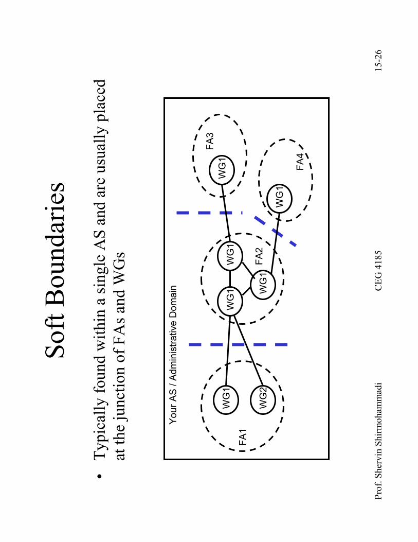
Soft Boundaries
•Typically found within a single AS and are usually placed
at the junction of FAsand WGs
FA1
WG2
WG1
WG1
WG1
WG1
WG1
WG1
FA2
FA3
FA4
Your AS / Administrative Domain

Prof. Shervin Shirmohammadi
CEG 4185
15-27
Internet Routing
•The Internet uses hierarchical routing
•The Internet is split into AS’s
–AS corresponds to an administrative domain
–Assign each AS a 16-bit number
–Examples: University, company, backbone network
•Stanford (32), Sprint (1239), MCI Worldcom(17373)
•Within an AS, the administrator chooses an Interior
Gateway Protocol (IGP)
–Examples of IGPs: RIP (RFC 1058), OSPF (RFC 1247)
–Between AS’s, the Internet uses an Exterior Gateway Protocol
•AS’s today use the Border Gateway Protocol, BGP-4 (RFC 1771)
Prof. Shervin Shirmohammadi
CEG 4185
15-28
Why different Intra-and Inter-AS routing?
•Policy:
–Inter-AS: admin wants control over how its traffic is routed
•who routes through its net.
–Intra-AS: single admin, so no policy decisions needed
•Scale:
–hierarchical routing saves table size, update traffic
•Performance:
–Intra-AS: can focus on performance
–Inter-AS: policy may dominate over performance
Prof. Shervin Shirmohammadi
CEG 4185
15-29
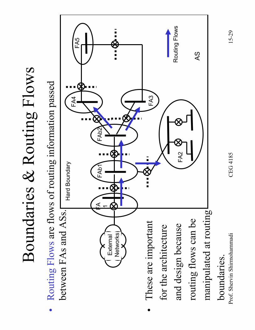
•Routing Flows are flows of routing information passed
between FAsand ASs.
•These are important
for the architecture
and design because
routing flows can be
manipulated at routing
boundaries.Boundaries & Routing Flows
FA 1
FAb1
FAb2
FA4
FA5
FA3
External
Networks
FA2
Routing Flows
AS
Hard Boundary
Prof. Shervin Shirmohammadi
CEG 4185
15-30
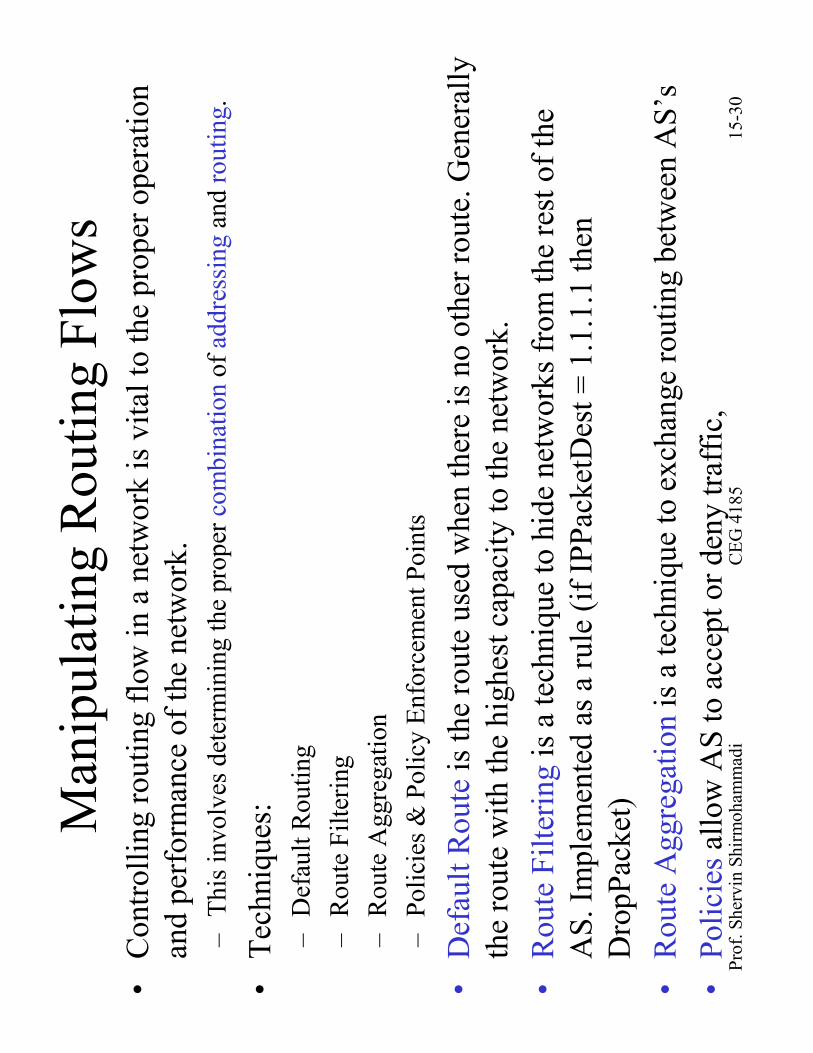
Manipulating Routing Flows
•Controlling routing flow in a network is vital to the proper operation
and performance of the network.
–This involves determining the proper combinationof addressingand routing.
•Techniques:
–Default Routing
–Route Filtering
–Route Aggregation
–Policies & Policy Enforcement Points
•Default Routeis the route used when there is no other route. Generally
the route with the highest capacity to the network.
•Route Filteringis a technique to hide networks from the rest of the
AS. Implemented as a rule (if IPPacketDest= 1.1.1.1 then
DropPacket)
•Route Aggregationis a technique to exchange routing between AS’s
•Policiesallow AS to accept or deny traffic,
Prof. Shervin Shirmohammadi
CEG 4185
15-31
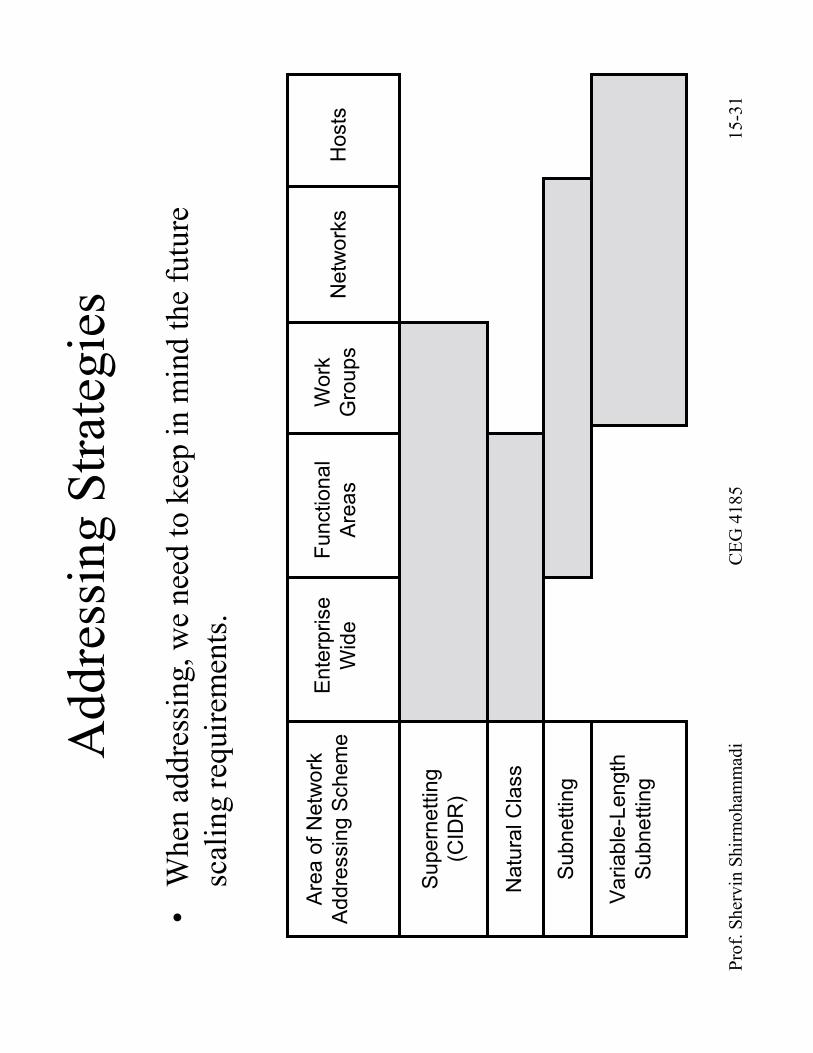
Addressing Strategies
•When addressing, we need to keep in mind the future
scaling requirements.
Area of Network
Addressing Scheme
Supernetting
(CIDR)
Natural Class
Subnetting
Variable-Length
Subnetting
Enterprise
Wide
Functional
Areas
Work
Groups
Networks
Hosts
Prof. Shervin Shirmohammadi
CEG 4185
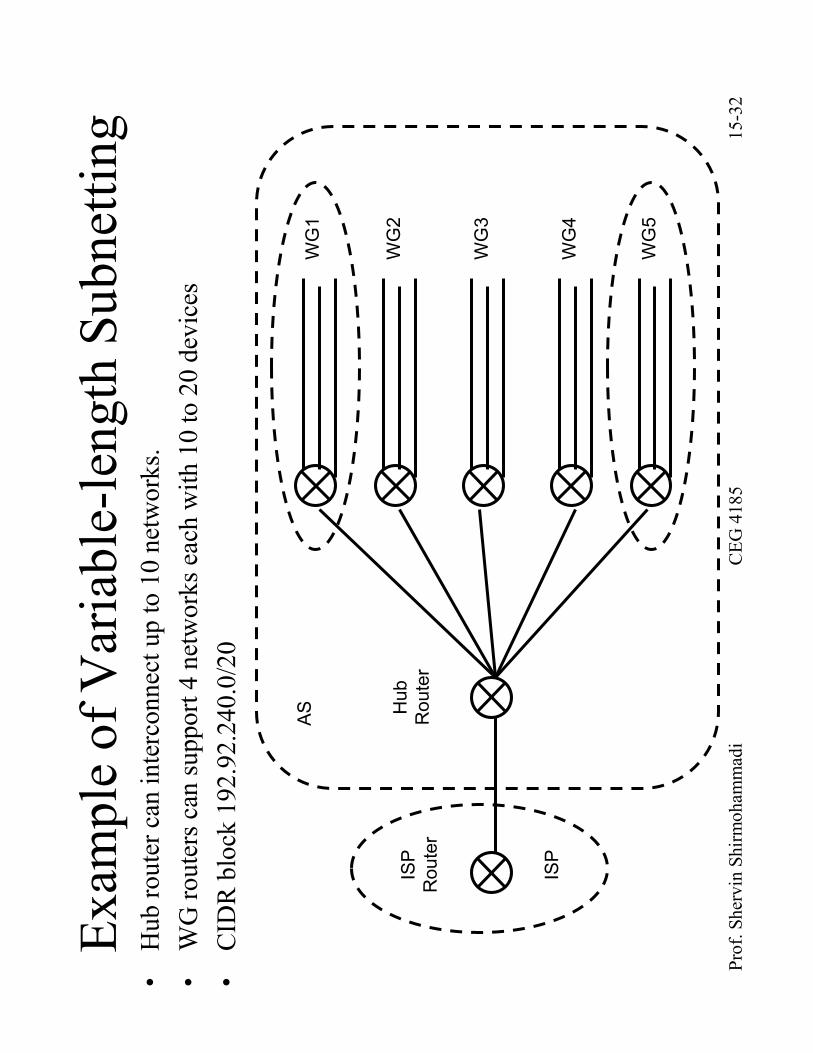
15-32
Example of Variable-length Subnetting
ISP
Router
ISP
WG1
WG2
WG3
WG4
WG5
Hub
Router
AS
•Hub router can interconnect up to 10 networks.
•WG routers can support 4 networks each with 10 to 20 devices
•CIDR block 192.92.240.0/20
Prof. Shervin Shirmohammadi
CEG 4185
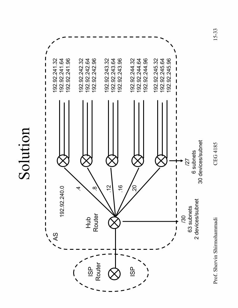
15-33
Solution
ISP
Router
ISP
192.92.241.32
192.92.241.64
192.92.241.96
Hub
Router
AS
192.92.242.32
192.92.242.64
192.92.242.96
192.92.243.32
192.92.243.64
192.92.243.96
192.92.244.32
192.92.244.64
192.92.244.96
192.92.245.32
192.92.245.64
192.92.245.96
/27
6 subnets
30 devices/subnet
/30
63 subnets
2 devices/subnet
192.92.240.0 .4 .8 .12
.16
.20