lecture 16 - text
TRANSCRIPT

8/16/2019 Lecture 16 - Text
http://slidepdf.com/reader/full/lecture-16-text 1/33
Module 6Fire Design
Contents:1. Construction materials at high temperatures
1.1. Steel1.2. Concrete
2. Temperatures in fires3. Behaviour of beams and columns in furnace tests4. Fire protection methods5. Simple urocode design of steel members
5.1. !oadings5.2. Basic principles of fire resistant design
". #aterial properties".1. Steel strengths".2. Concrete strengths".3. Thermal e$pansion of steel and concrete".4. %ther relevant thermal properties of steel
&. Section classification'. Critical temperature(. )esistance of tension members1*.)esistance of beams11.!ateral+torsional buc,ling12.)esistance of compression members
13.Fire resistance time of unprotected steel members14.Fire resistance times of protected steel members15.-se of advanced calculation models1". urocode simple fire resistance calculation e$amples
1".1. esign e$ample1".2. Fire )esistance and /rotection of a Tension #ember
1".2.1. 0mbient temperature design of B1".2.2. Fire resistance of tension member B1".2.3. Fire protection of tension member B
1".3. Fire )esistance and /rotection of a Steel Beam1".3.1. 0mbient temperature design of minor beam 0B1".3.2. Fire resistance of minor beam 0B
1".3.3. Fire protection of minor beam 0B1".4. Fire )esistance and /rotection of a Steel Column
1".4.1. 0mbient temperature design of column
Februar 2**( page 1 33
Lecture 16: Introduction to fire designaccording to Eurocode 3
8/16/2019 Lecture 16 - Text
http://slidepdf.com/reader/full/lecture-16-text 2/33
Design of Tubular Steel StructuresLecture 16 Introduction to fire design according to Eurocode 3
1".4.2. Fire resistance of steel column 1&.)eferences
Februar 2**( page 2 33

8/16/2019 Lecture 16 - Text
http://slidepdf.com/reader/full/lecture-16-text 3/33
Design of Tubular Steel StructuresLecture 16 Introduction to fire design according to Eurocode 3
1. Construction materials at ig tem!eratures
1.1. Steel
#ost construction materials suffer a progressive loss of strength and stiffness as their temperature increases. For steel the change can be seen in urocode 3 stress+straincurves Figure 1 6 at temperatures as lo7 as 2**8C. 0lthough melting does not happenuntil about 15**8C9 onl 23: of the ambient+temperature strength remains at &**8C. 0t'**8C this has reduced to 11: and at (**8C to ":.
Part 1-23.2
Table 3.1 Fig. 3.1
Strain (%)
300
250
200
150
100
50
0 0,5 1,0 1,5 2,0
Stress (N/mm )2
20 !
200 !
300 !
"00 !
500 !
600 !
#00 !
$00 !
ro&ortiona' 'imit (600 !)
Effecti e ie'd strengt* (600 !)
E'astic modu'us (600 !)
Figure 1 +odifications of stress strain re'ations*i&s -it* tem&erature for S2#5stee' (Eurocode 3 cur es).
1.". Concrete
Concrete also loses strength properties as its temperature increases Figure 2 6. EC4 Part 1-2
Februar 2**( page 3 33

8/16/2019 Lecture 16 - Text
http://slidepdf.com/reader/full/lecture-16-text 4/33
Design of Tubular Steel StructuresLecture 16 Introduction to fire design according to Eurocode 3
Figure " Eurocode " stress strain tem&erature cur es for ca'careous concrete
Concrete has a lo7er thermal conductivit than steel and is therefore a relativel good
insulator to reinforcement or embedded parts of sections. Fire resistance of reinforcedconcrete members tends to be based on the strength reduction of reinforcement 7hich islargel controlled b the cover specification. o7ever9 concrete is affected b spalling97hich is a progressive brea,ing a7a of concrete from the fire+e$posed surface 7heretemperature variation is high9 and this can lead to the e$posure of reinforcement as a fire
progresses. ;ts behaviour at elevated temperatures depends largel on the aggregate t peused< siliceous gravel9 granite6 aggregate tends to cause concrete to spall more readilthan calcareous limestone6 aggregate. igh strength concrete are more prone tospalling9 presumabl because of their lo7er gas permeabilit . !ight7eight concrete
possesses greater insulating properties than normal+7eight concrete.
". Tem!eratures in fires
0 real fire in a building gro7s and deca s in accordance 7ith the mass and energ balance 7ithin the compartment in 7hich it occurs Figure 3 6. The energ releaseddepends upon the =uantit and t pe of fuel available. The rate at 7hich the energ isreleased depends upon the ventilation conditions and t pe of fuel.
Februar 2**( page 4 33

8/16/2019 Lecture 16 - Text
http://slidepdf.com/reader/full/lecture-16-text 5/33
Design of Tubular Steel StructuresLecture 16 Introduction to fire design according to Eurocode 3
Ignition Smou'dering
re 'as*o er ost 'as*o er 1000 1200 !
'as*o er
Ignition
Start of fire
e -ords eating !oo'ingime
!ontro' Inf'amma4i'it em&./smo ede e'o&ment
ire 'oaddensit
enti'ation
IS7$3" standardfire cur e
Natura' fire cur e
em&erature
Figure 3 %*ases of a natura' fire, comå atmos&*ere tem&eratures -it* t*eIS7$3" standard fire cur e
;t is possible to consider a real fire as consisting of three phases9 7hich ma be definedas gro7th9 full development and deca . The most rapid temperature rise occurs in the
period of flashover9 7hich is the point at 7hich all organic materials in the compartmentspontaneousl combust.
Fire resistance times specified in most national building regulations relate to heatingaccording to an internationall agreed time+temperature curve defined in ;S%'34 or
urocode 1 /art 1+269 7hich does not represent an t pe of natural building fire. ;t ischaracterised b an atmosphere temperature 7hich rises continuousl 7ith time9 but at adiminishing rate Figure 4 6. This standard design curve is s stematicall used in furnacetesting of components. The =uoted value of fire resistance time does not thereforeindicate the actual time for 7hich a component 7ill survive in a building fire9 but should
be used for rating different structural s stems against each other.
The proposed >e$ternal fire curve? is not to be used for cases 7here the structure for 7hich the fire resistance is being considered as e$ternal9 but 7hen the e$ternal fa@ade of a building is subAected to a fire from another building.
Februar 2**( page 5 33

8/16/2019 Lecture 16 - Text
http://slidepdf.com/reader/full/lecture-16-text 6/33
Design of Tubular Steel StructuresLecture 16 Introduction to fire design according to Eurocode 3
300
100
200
0
"00
500
600
#00
$00
800
1000
0 600 1200 1$00 2"00 3000 3600
ime (sec)
9as em&erature ( !)
5#6
6#5#38#$1$"2
8"5
Figure # :tmos&*ere tem&erature for IS7$3" standard fire
;n cases 7here storage of h drocarbon materials ma,es fires e$tremel severe a> drocarbon Fire? curve is also given. These three > ominal? fire curves are sho7n inFigure 5 .
EC1 Part 1-2
3.2
0
200
"00
600
$00
1000
1200
0 600 1200 1$00 2"00 3000 3600ime (sec)
9as em&erature ( !)
E;terna' ire
Standard ire
drocar4on ire
&ica' arametricfire cur e
Figure $ Eurocode 1 %art 1 2 nomina' fire cur es com&ared -it* a &arametric fire
0n of the normal means of establishing fire resistance times tabulated data or calculation models6 ma be used against these curves.0n alternative method to the use of nominal fire curves9 7hich ma onl be used directl EC1 Part 1-
Februar 2**( page " 33

8/16/2019 Lecture 16 - Text
http://slidepdf.com/reader/full/lecture-16-text 7/33
Design of Tubular Steel StructuresLecture 16 Introduction to fire design according to Eurocode 3
7ith fire resistance calculation models9 is to attempt to model a natural fire using a>parametric? fire curve for 7hich e=uations are provided in urocode 1 /art 1+2. Thisenables fairl simple modelling of fire temperatures evolution in the heating and cooling
phases of the post+flashover fire the initial gro7th phase is not addressed6. ;t isnecessar to have data on the properties densit 9 specific heat9 thermal conductivit 6 of the materials enclosing a compartment9 the fire load fuel6 densit and ventilation areas7hen using these e=uations. The are limited in application to compartments of up tofloor area of 5** m29 floor to ceiling distance up to 4 m and no opening in the ceiling97ith mainl cellulosic paper9 7ood9 etc.6 fire loads.
2 Annex A, E
;t ma be advantageous to the designer to use parametric curves in cases 7here thedensit of combustible materials is lo79 7here using the nominal fire curves isunnecessaril conservative.
0nother concept ,no7n as e=uivalent timeD can also be used both to relate theresistance times of structural elements in a real fire to their resistance in the standardfire. The principle is sho7n in Figure ". This concept can onl be applied 7here the
behaviour of the structure is dictated b a single temperature such as the supposedluniform temperature of a steel member. The application is more =uestionable incomposite structures 7here the temperature field is highl non uniform.
EC1 Part 1-2
Annex F
Figure 6 ime e<ui a'ent se erit of natura' fires
This is useful in appl ing calculation models 7hich are based on the standard fire
heating curve9 but the important aspect of using parametric fire curves and thecalculated structure temperatures 7hich come from these is that the represent anabsolute test of structural fire resistance b comparing the ma$imum temperature
Februar 2**( page & 33

8/16/2019 Lecture 16 - Text
http://slidepdf.com/reader/full/lecture-16-text 8/33
Design of Tubular Steel StructuresLecture 16 Introduction to fire design according to Eurocode 3
reached b the structure against its critical temperature9 rather than an assessment of the7a it 7ould perform if it 7ere possible to subAect it to a standard fire time+temperaturecurve based on furnace testing.
3. %e a&iour of beams and columns in furnace tests
Furnace testing using the standard time+temperature atmosphere curve 7as historicallthe traditional means of assessing the behaviour of frame elements in fire9 but thedifficulties of conducting furnace tests of representative full+scale structural membersunder load are obvious. The siEe of furnaces limits the siEe of the members tested9usuall to less than 5 m9 and if a range of load levels is re=uired then a separatespecimen is re=uired for each of these. Tests on small members ma be unrepresentativeof the behaviour of larger members.
0 further serious problem 7ith the use of furnace tests in relation to the behaviour of similar elements in structural frames is that the onl clearl defined and reliable supportcondition for a member in a furnace test is simpl supported9 7ith the member free toe$pand a$iall . hen a member forms part of a fire compartment surrounded badAacent structure 7hich is unaffected b the fire its thermal e$pansion is resisted brestraint from this surrounding structure.
This is a problem 7hich is uni=ue to the fire state9 because at ambient temperaturesstructural deflections are so small that a$ial restraint is ver rarel an issue of significance. 0$ial restraint can in fact 7or, in different 7a s at different stages of afire< in the earl stages the restrained thermal e$pansion dominates9 and ver highcompressive stresses are generated9 but in the later stages 7hen the 7ea,ening of thematerial is ver high the restraint ma begin to support the member b resisting pull+in.Furnace tests 7hich allo7 a$ial movement cannot reproduce these restraint conditions atall< in particular9 in the later stages a complete collapse 7ould be observed unless asafet cut+off criterion is applied. ;n fact a beam furnace test is al7a s terminated at adeflection of not more than span 2* for e$actl this reason.
hen an element is part of a structural frame9 not onl restraint to a$ial e$pansion9 butalso rotational restraint ma be present at the ends of the element. This restraint is alsochanging during the course of the fire. )otational restraint is usuall not applied duringa furnace test on single elements.
%nl recentl has an significant number of fire tests been performed on firecompartments 7ithin 7hole structures. Some ears ma pass before these full+scale testsare seen to have a real impact on design codes. ;n fact full+scale testing is so e$pensivethat there 7ill probabl never be a large volume of documented results from such tests9and those that e$ist 7ill have the maAor function of being used to validate numericalmodels on 7hich future developments of design rules 7ill be based. The basic design
procedures of urocode 3 and 4 for use in routine fire engineering design are still interms of isolated members for 7hich fire resistance is considered mainl in terms of areal or simulated furnace test. Get9 urocodes 3 and 4 allo7 for the use of advancedcalculation models9 and these are more and more often used9 at least in proAects of acertain siEe and comple$it .
#. Fire !rotection met ods
The traditional approach to fire resistance of steel structures has been to clad themembers 7ith insulating material. This ma be in alternative formsH
Februar 2**( page ' 33

8/16/2019 Lecture 16 - Text
http://slidepdf.com/reader/full/lecture-16-text 9/33
Design of Tubular Steel StructuresLecture 16 Introduction to fire design according to Eurocode 3
Boarding plasterboard or more specialised s stems based on mineral fibre or vermiculite6 fi$ed around the e$posed parts of the steel members. This is fairl easto appl and creates an e$ternal profile 7hich is aestheticall acceptable9 but isinfle$ible in use around comple$ details such as connections. Ceramic fibre blan,etma be used as a more fle$ible insulating barrier in some cases<Spra s 7hich build up a coating of prescribed thic,ness around the members. Thesetend to use vermiculite or mineral fibre in a cement or g psum binder. 0pplication onsite is fairl rapid9 and does not suffer the problems of rigid boarding aroundcomple$ structural details. Since the finish produced tends to be unacceptable in
public areas of buildings these s stems tend to be used in areas 7hich are normallhidden from vie79 such as beams and connections above suspended ceilings<;ntumescing paints9 7hich provide a decorative finish under normal conditions9 but7hich foam and s7ell 7hen heated9 producing an insulating char la er 7hich is up to5* times as thic, as the original paint film. The are applied b brush9 spra or roller9 and must achieve a specified thic,ness 7hich ma re=uire several coats of
paint and measurement of the film thic,ness.
0ll of these methods are normall applied as a site operation after the main structuralelements are erected. This can introduce a significant dela into the construction
process9 7hich increases the cost of construction to the client. The onl e$ception to thisis that some s stems have recentl been developed in 7hich intumescents are applied tosteel7or, at the fabrication stage9 so that much of the site+7or, is avoided. o7ever9 insuch s stems there is clearl a need for a much higher degree than usual of resistance toimpact or abrasion.
These methods can provide an re=uired degree of protection against fire heating of steel7or,9 and can be used as part of a fire engineering approach. o7ever traditionallthic,nesses of the protection la ers have been based on manufacturersD data aimed at therelativel simplistic criterion of limiting the steel temperature to less than 55*8C at there=uired time of fire resistance in the ;S%'34 standard fire. ;n some cases9 material
properties for design are determined from the results b semi+empirical means.
Full or partial encasement of open steel sections in concrete is occasionall used as amethod of fire protection9 particularl in the case of columns for 7hich the strength of the concrete9 either reinforced or plain9 can contribute to the ambient+temperaturestrength. ;n the case of hollo7 steel sections concrete ma be used to fill the section9again either 7ith or 7ithout reinforcing bars. ;n fire this concrete acts to some e$tent asa heat+sin,9 7hich slo7s the heating process in the steel section. For significant firedurations9 this effect is not maintained because the temperature of the e$ternal steel tube
tends to7ard the temperature of the hot gases< the s stem finall behaves as a reinforcedconcrete column 7ith the steel tube having lost nearl all load bearing capacit . The positive effect that remains is that no part of concrete can leave the tube as a result of progressive spalling9 7hereas this is often observed in usual concrete columns. ;n a fe7 buildings hollo7+section columns have been lin,ed together as a s stem and filled 7ith7ater fed from a gravit reservoir. This can clearl dissipate huge amounts of heat9 butat rather high cost9 both in construction and maintenance.
The most recent design codes are e$plicit about the fact that the structural fire resistanceof a member is dependent to a large e$tent on its loading level in fire and also thatloading in the fire situation has a ver high probabilit of being considerabl less thanthe factored loads for 7hich strength design is performed6. This presents designers 7ithanother option 7hich ma be used alone or in combination 7ith other measures. 0reduction in load level b selecting steel members 7hich are stronger than is needed for ambient temperature strength9 possibl as part of a strateg of standardising sections9
Februar 2**( page ( 33

8/16/2019 Lecture 16 - Text
http://slidepdf.com/reader/full/lecture-16-text 10/33
Design of Tubular Steel StructuresLecture 16 Introduction to fire design according to Eurocode 3
can enhance the fire resistance times. This can allo7 unprotected elements to be used9 atleast for a duration of standard fire up to 3* minutes.
0lternative fire engineering strategies are be ond the scope of this lecture9 but there isan active encouragement to designers in the urocodes to use agreed and validatedadvanced calculation models for the behaviour of the 7hole structure or sub+assemblies.The clear implication of this is that designs 7hich can be sho7n to gain fire resistanceoverall b providing alternative load paths 7hen members in a fire compartment haveindividuall lost all effective load resistance are perfectl valid under the provisions of these codes. This is a maAor departure from the traditional approach based on the fireresistance of each component. ;n its preamble urocode 3 /art 1+2 also encourages theuse of integrated fire strategies9 including the use of combinations of active sprin,lers6and passive protection. 0 method is provided in urocode 1 /art 1+2 that allo7s areduction of the design value of the fire load depending on the active protection
measures9 but this applicabilit of this method is a matter for national Building)egulations through the ational 0pplication ocument that each #ember State has to
produce.
EC1, Part 1-2, Annex E
$. Sim!le Eurocode design of steel members
$ample design calculation using urocode 3 simple calculation models are given later9and so this section concentrates on the principles of these methods rather than their detail.
urocodes use a ver s stematic notation in 7hich different s mbols are used for general and particular versions of parameters. For e$ample an >effect of an action? isdenoted in general terms as E in establishing a principle< in particular members thismight become the a$ial force N or the internal bending moment M . Subscripts denotingdifferent attributes of a parameter ma be grouped9 using dots as separators9 as in E fi.d.t
7hich denotes the design value of the effect of an action in fire9 at the re=uired time of resistance. Commonl used notations in the fire engineering parts of urocodes 19 3 and4 areH
E effect of actions permanent action
! variable action " fi load+bearing resistancet fi standard fire resistance time of a member t fi,re#$ standard fire resistance time nominal re=uirementθ temperatureθ %r criticalI temperature of a member γ partial safet factor ψ load combination factor
Part 1-21.&
and the follo7ing subscript indices ma be used alone or in combinationH
A accidental design situation%r critical value
fi relevant to fire design
d design valueθ associated 7ith certain temperature ma be replaced b value6' characteristic value
Februar 2**( page 1* 33

8/16/2019 Lecture 16 - Text
http://slidepdf.com/reader/full/lecture-16-text 11/33
Design of Tubular Steel StructuresLecture 16 Introduction to fire design according to Eurocode 3
t at certain fire e$posure time ma be replaced b value6
19 2 ... ran,ing order for fre=uenc of variable actions
$.1. Loadings
urocode 1 /art 1+2 presents rules for calculating design actions loadings6 in fire97hich recognise the lo7 probabilit of a maAor fire occurring simultaneousl 7ith highload intensities. The normal urocode classification of loads is as permanent andvariable< in fire the characteristic permanent actions dead loading6 are used unfactoredγ A J 19*6 7hile the principal characteristic variable action imposed loading6 is
factored do7n b a combination factor ψ fi that is ta,en either for =uasi permanent valueψ 291 or for fre=uent value ψ 1919 to be chosen in the .0. . b each member state9 and7hose value is bet7een *92 and *9( depending on the t pe of loading 7ind9 sno79 liveload6 and building usage.
EC1 Part 1-2
4.3.1
here indirect fire actions9 i.e. effects of thermal e$pansion9 need not be e$plicitlconsidered9 effects of actions ma be determined b anal sing the structure for combinedactions for t J * onl and these effects are ta,en as constant throughout fire e$posure.
EC1 Part 1-2
4.3.2
0s a further simplification9 the design effect of actions during the fire E fi,d can becalculated from those determined in normal temperature design on the base of thefactored design loadsH
. fi d fi d E E η = Part 1-22.4.2 (3)
For steel members 9this factor η fi ma be e$pressed in terms of the characteristic loadsand their factors 7hen onl the principal variable action is used together 7ith the
permanent action asH
EC4 part 1-22.4.2 (2)
91
91 91
A ' fi ' fi
' ! '
!
!
γ ψ η
γ γ +=+
T pical values of the safet factors specified in urocode 1 areH
γ A J 19* /ermanent loadsH accidental design situations6ψ fi J ψ 291 J *93 Combination factorH variable loads9 office buildings6
γ J 1935 /ermanent loadsH strength design6γ K91 J 195 Lariable loadsH strength design6
$.". %asic !rinci!les of fire resistant design
Structural fire+resistant design of a member is concerned 7ith establishing that itsatisfies the re=uirements of national building regulations over the designated time
period 7hen subAected to the appropriate fire curve. This can be e$pressed in threealternative 7a sH
The fire resistan%e time should e$ceed the re=uirement for the building usage andt pe 7hen loaded to the design load level and subAected to the fire temperature curveH
EC1 Part 1-2
2.*
Februar 2**( page 11 33

8/16/2019 Lecture 16 - Text
http://slidepdf.com/reader/full/lecture-16-text 12/33
Design of Tubular Steel StructuresLecture 16 Introduction to fire design according to Eurocode 3
re#$ fid fi t t 99 ≥
The l+ad-bearing resistan%e of the element should e$ceed the design loading at antime during the fire and until 7hen it has been heated for the re=uired time in the fireH
t d fit d fi E "9999
≥
The critical temperature of an element loaded to the design level should e$ceed thedesign temperature at an time during the fire and until the re=uired time thisapproach is onl possible 7hen the behaviour of the member is governed b onesingle representative temperature as is the case9 for e$ample9 for steel members atuniform temperature6H
d d %r θ θ ≥9
6. Material !ro!erties
6.1. Steel strengt s
0 set of stress+strain curves for S2&5 steel has alread been sho7n in Figure 1 as ane$ample of the principal effect of temperature in 7ea,ening steels.
Part 1-2 Fig. 3.2
Figure ' Eurocode 3 Strengt* reduction for structura' stee' (SS) and co'd -or edreinforcement (=ft) at *ig* tem&eratures
EC4 Part 1-2
These are based on an e$tensive series of tests9 7hich have been modelled b e=uations
Februar 2**( page 12 33

8/16/2019 Lecture 16 - Text
http://slidepdf.com/reader/full/lecture-16-text 13/33
Design of Tubular Steel StructuresLecture 16 Introduction to fire design according to Eurocode 3
representing an initial linear elastic portion9 changing tangentiall to a part+ellipse 7hosegradient is Eero at 2: strain. hen curves such as these are presented in normalisedfashion9 7ith stresses sho7n as a proportion of ambient+temperature ield strength9 thecurves at the same temperatures for S2359 S2&59 S3559 S42* and S4"* steels of
1**25 and all steel grades defined in 1*21* and 1*21( are e$tremel closeto one another. ;t is therefore possible to use a single set of strength reduction factorsFigure &6 for all three grades9 at given temperatures and strain levels. ;n urocodes 3
and 4 strengths corresponding to 2: strain are used in the fire engineering design of allt pes of structural members.
ot+rolled reinforcing bars are treated in urocode 4 in similar fashion to structuralsteels9 but cold+7or,ed reinforcing steel9 7hose standard grade is S5**9 deterioratesmore rapidl at elevated temperatures than do the standard grades. ;ts strength reductionfactors for effective ield and elastic modulus are also sho7n on Figure &.
6.". Concrete strengt s
The stress+strain curves at different temperatures for concrete have a significantdifference in form from those for steel. The curves all have a ma$imum compressivestrength9 rather than an effective ield strength9 7hich occurs at strains 7hich
progressivel increase 7ith temperature9 follo7ed b a descending branch. Tensilestrength for all concretes is normall considered to be Eero. 0s is normal in urocodes9alternative material constitutive la7s ma be used provided that the are supported be$perimental evidence.
For normal+7eight concretes densit around 24** 'g m36 onl the lo7er range of
strength values9 corresponding to the siliceous t pe 7hich is sho7n in Figure ' 9 aretabulated in urocode 4 /art 1+2. For calcareous+aggregate concrete these are also used9 being inherentl conservative values. here more detail is re=uired designers arereferred to urocode 2 /art 1+2.
Februar 2**( page 13 33

8/16/2019 Lecture 16 - Text
http://slidepdf.com/reader/full/lecture-16-text 14/33
Design of Tubular Steel StructuresLecture 16 Introduction to fire design according to Eurocode 3
Figure ( Eurocode " strengt* reduction for norma' -eig*t si'iceous concrete and'ig*t-eig*t concrete at e'e ated tem&eratures
EC4 Part 1-2
!ight7eight concretes are defined as those 7ithin the densit range 1"**+2*** 'g m3.0lthough in practice the ma be created using different forms of aggregate9 the aretreated in urocode 4 /art 1+2 as if the degrade similarl 7ith temperature. ence the
single set of strength reduction factors Figure ' 6 for light7eight concrete is again on theconservative side.
6.3. T ermal e)!ansion of steel and concrete
;n most simple fire engineering calculations on simple elements e$posed to the standardfire9 thermal e$pansion of materials is neglected. hen larger structures are consideredand more advanced calculation models are used9 it is necessar to recognise that thermale$pansion in the structure around the fire compartment is resisted b the cool structureoutside this Eone9 and that this causes behaviour 7hich is considerabl different fromthat e$perienced b similar members in an unrestrained situation. ;t is thereforenecessar at least to appreciate the 7a in 7hich the thermal e$pansion coefficients of
steel and concrete var 7ith temperature. The are sho7n in Figure ( < perhaps the mostsignificant aspect to note is that the thermal e$pansion coefficients of steel and concreteare of comparable magnitudes in the practical range of fire temperatures.
Februar 2**( page 14 33
8/16/2019 Lecture 16 - Text
http://slidepdf.com/reader/full/lecture-16-text 15/33
Design of Tubular Steel StructuresLecture 16 Introduction to fire design according to Eurocode 3
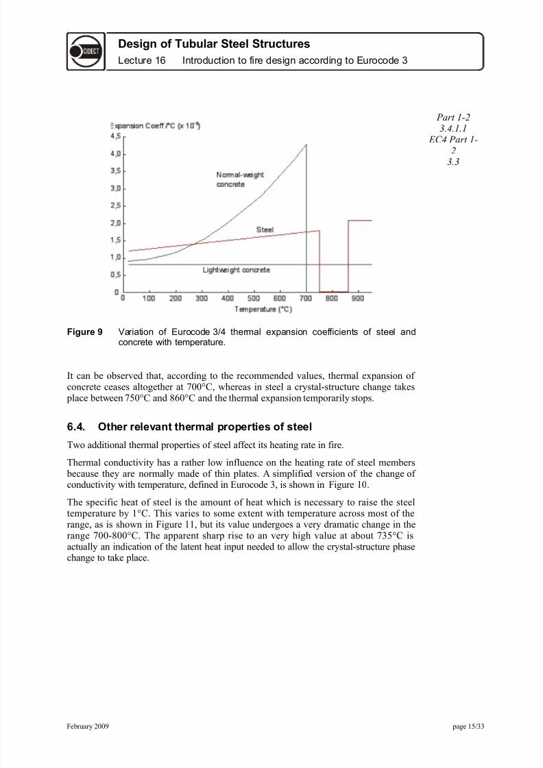
Figure * ariation of Eurocode 3/" t*erma' e;&ansion coefficients of stee' andconcrete -it* tem&erature.
Part 1-23.4.1.1
EC4 Part 1-2
3.3
;t can be observed that9 according to the recommended values9 thermal e$pansion of concrete ceases altogether at &**8C9 7hereas in steel a cr stal+structure change ta,es
place bet7een &5*8C and '"*8C and the thermal e$pansion temporaril stops.
6.#. +t er rele&ant t ermal !ro!erties of steel
T7o additional thermal properties of steel affect its heating rate in fire.
Thermal conductivit has a rather lo7 influence on the heating rate of steel members because the are normall made of thin plates. 0 simplified version of the change of conductivit 7ith temperature9 defined in urocode 39 is sho7n in Figure 1* .
The specific heat of steel is the amount of heat 7hich is necessar to raise the steeltemperature b 18C. This varies to some e$tent 7ith temperature across most of therange9 as is sho7n in Figure 11 9 but its value undergoes a ver dramatic change in the
range &**+'**8C. The apparent sharp rise to an ver high value at about &358C isactuall an indication of the latent heat input needed to allo7 the cr stal+structure phasechange to ta,e place.
Februar 2**( page 15 33

8/16/2019 Lecture 16 - Text
http://slidepdf.com/reader/full/lecture-16-text 16/33
Design of Tubular Steel StructuresLecture 16 Introduction to fire design according to Eurocode 3
Figure 1, Eurocode 3 re&resentations of t*e ariation of t*erma' conducti it of stee' -it* tem&erature
Part 1-23.4.1.3
Figure 11 ariation of t*e s&ecific *eat of stee' -it* tem&erature
Part 1-23.4.1.2
'. Section classification
;t is essential for both the ambient+temperature and fire design of all members 7hich act
7holl or partl in compression that the are classified in order to establish theappropriate design calculation methods to be used. This is basicall a chec, on theslenderness of the parts of the cross+section 7hich act in compression in order to assess
Februar 2**( page 1" 33
8/16/2019 Lecture 16 - Text
http://slidepdf.com/reader/full/lecture-16-text 17/33
Design of Tubular Steel StructuresLecture 16 Introduction to fire design according to Eurocode 3
their vulnerabilit to local buc,ling. This applies Aust as much in fire as in normaldesign9 since the strain levels in fire are liable to become ver high9 and since strengthsare reduced in fire these elevated+temperature material properties should be used 7hen
performing a section classification. ;t is 7orth re+stating briefl the definitions of thefour possible classes of memberH
Class 1 sectionsH stoc, cross+sections 7hich can be used reliabl in plastic strengthcalculations because the can develop plastic bending moment capacit 7ith asufficient capacit of rotation<Class 2 sectionsH 7hilst the member resistance ma be calculated on the basis of its
plastic capacit 9 it is not capable of sufficient e$tra rotation 7ithout the occurrenceof local buc,ling to allo7 other hinges to form as part of a full developedmechanism. The frame should therefore be designed elasticall but based on plasticmoment capacit in the sections<
Class 3 sectionsH the member resistance should be calculated elasticall at its initialield capacit <
Class 4 sectionsH slender cross+sections 7hose resistance is governed b elastic local buc,ling belo7 the ield strength of the material.
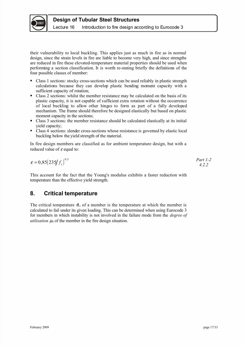
;n fire design members are classified as for ambient temperature design9 but 7ith areduced value of ε e=ual toH
( ) *9 5
*9'5 235 - f ε = Part 1-2
4.2.2
This account for the fact that the GoungMs modulus e$hibits a faster reduction 7ith
temperature than the effective ield strength.
(. Critical tem!erature
The critical temperature θ %r of a member is the temperature at 7hich the member iscalculated to fail under its given loading. This can be determined 7hen using urocode 3for members in 7hich instabilit is not involved in the failure mode from the degree +f $tilisati+n µ * of the member in the fire design situation.
Februar 2**( page 1& 33

8/16/2019 Lecture 16 - Text
http://slidepdf.com/reader/full/lecture-16-text 18/33
Design of Tubular Steel StructuresLecture 16 Introduction to fire design according to Eurocode 3
Figure 1" !ritica' tem&erature, re'ated to degree of uti'isation
Part 1-24.2.4
The follo7ing e=uation9 plotted in Figure 129 defines the critical temperatureH
39'33*
13(91( ln 1 4'2
*9("&4%r θ µ
= − +
Part 1-24.2.4
This e=uation is in fact an appro$imate best fit e=uation to this invert of the effectiveield strength of carbon steel as a function of the temperature. For the ver slender
Class 4 sections9 a single conservative critical temperature of 35*8C is specified. Thecritical temperature of Class 4 sections ma be calculated and found higher than 35*8Cif calculated according to 0nne$ of urocode 3 /art 1+2.
Part 1-24.2.3.&
The degree of utilisation µ * is basicall the design loading in fire as a proportion of thedesign resistance9 7here the latter is calculated at ambient temperature or at time t J *6
but using the material partial safet factors 7hich appl in fire design rather than innormal strength designH
9*
9 9*
fi d
fi d
E "
µ =
0 simple conservative version9 7hich can be used for elements 7here instabilit is not a possibilit 9 is
9*
*
M fi fi
M
γ µ η
γ = ÷
in 7hich the reduction factor η fi ma alread be conservative.
*. -esistance of tension members
Februar 2**( page 1' 33

8/16/2019 Lecture 16 - Text
http://slidepdf.com/reader/full/lecture-16-text 19/33
Design of Tubular Steel StructuresLecture 16 Introduction to fire design according to Eurocode 3
For a tension member under uniform cross+sectional temperature θ the design resistancein fire is calculated simpl b using the reduction factor ' ,θ on ield strength at elevatedtemperature9 7ith an adAustment for the relative material safet factors in normal designand fire designH
Part 1-24.2.3.1
*9 9 9
9
M fi "d - "d
M fi
N ' N θ θ γ γ
= ÷ ÷
so that the degree of utilisation is simpl H
9 9 9*
92*9 *
fi d fi d M fi
fi "d "d M
N N
N N
γ µ
γ = = ÷
1,. -esistance of beams
#oment resistance in fire for Class 1 or 2 sections 7ith uniform cross+sectionaltemperature θ is again calculated from the normal plastic resistance moment for strengthdesign9 simpl b using the reduction factor ' ,θ on ield strength at elevated
temperature9 7ith an adAustment for the relative material safet factors in normal designand fire designH
4.2.3.3
*9 9 9
9
M fi "d - "d
M fi
M ' M θ θ γ γ
= ÷ ÷
For a Class 3 section the same e$pression applies9 but 7ith the elastic moment of resistance used for M "d .
4.2.3.4
;n the case of beams supporting concrete slabs on the top flange the non+uniformtemperature distributions ma be accounted for anal ticall in calculating the design
moment resistance9 b dividing the cross+section into uniform+temperature elements9reducing the strength of each according to its temperature9 and finding the resistancemoment b summation across the section. 0lternativel it ma be dealt 7ithconservativel b the use of t7o empirical adaptation factors κ 1 and κ 2 to define themoment resistance at time t asH
9 99 9
1 2
fi "d fi t "d
M M θ
κ κ =
7here κ 1 is the factor for non+uniform cross+sectional temperature and κ 2 is the factor for temperature reduction to7ards the supports of a staticall indeterminate beam. Theactual values of κ 1 and κ 2 are specified in ational 0pplication ocuments. #ancountries are using values of κ 1 higher than the value of *9& recommended in the
Februar 2**( page 1( 33

8/16/2019 Lecture 16 - Text
http://slidepdf.com/reader/full/lecture-16-text 20/33
Design of Tubular Steel StructuresLecture 16 Introduction to fire design according to Eurocode 3
urocode because this value 7as based on e$perimental test results made in the -N in7hich some ,ind of connection 7as present bet7een the steel profiles and thesupposedl non collaborating concrete slabs.
Shear resistance is determined using the same general process as for bending and tensionresistance9 7ith the same adaptation factors as those above in cases 7ith non+uniformtemperature distribution. The general e$pression9 covering uniform and non+uniformtemperature cases9 isH
*9 9 9 9
9
M fi t "d - .eb "d
M fi
/ ' / θ γ γ
= ÷ ÷
11. Lateral torsional buc/ling
;n cases 7here the compression flange is not continuousl restrained the designresistance moment against lateral+torsional buc,ling is calculated for Class 1 or 2sections using the formula from urocode 3 /art 1+19 7ith minor amendment for the firestateH
4.2.3.3
9 9 9 9 9 9 99
1b fi t "d pl - - %+m - 0T fi
M fi
M ' f θ χ γ
=
7ithH
χ 0T,fi lateral+torsional buc,ling reduction factor in fire design situation' ,θ,%+m ield strength reduction factor at the ma$imum compression flange
temperature at time t
The lateral+torsional buc,ling reduction factor χ 0T is determined 7ith a special instabilitcurve for the fire situation9 7ith the normalised slenderness adapted to the high+temperature steel propertiesH
9 99 9
9 9
- %+m 0T %+m 0T
E %+m
'
' θ
θ θ
λ λ =
7ithH
' E,θ ,%+m elastic modulus reduction factor at the ma$imum compression flangetemperature at time t
1". -esistance of com!ression members
The design buc,ling resistance of columns of Class 19 2 or 3 is calculated as follo7s9allo7ing for a reduction in strength and an increase in normalised slenderness at hightemperatures.
4.2.3.2
Februar 2**( page 2* 33

8/16/2019 Lecture 16 - Text
http://slidepdf.com/reader/full/lecture-16-text 21/33
Design of Tubular Steel StructuresLecture 16 Introduction to fire design according to Eurocode 3
9 9 9 9 9ma$9
1b fi t "d - - fi
M fi N A' f θ χ γ =
The buc,ling reduction factor χ fi is the lo7er of its values about the and a$esdetermined as in ambient+temperature design9 e$cept that the normalised slendernessused is adapted to the fire situation as follo7sH
0 special buc,ling curve for the fire situation is used9 based on the slenderness at thecritical temperature<The buc,ling length l fi is determined as sho7n in Figure 139 provided that each storeof the building comprises a separate fire compartment9 and that the fire resistance of the compartment boundaries is not less than that of the column. Because thecontinuing columns are much stiffer than the column in the fire compartment it isassumed that the cause the end s6 of the heated column to be restrained in rotation9so the effective length factor is ta,en as *95 for intermediate store s and *9& for thetop store .
Figure 13 >uc 'ing 'engt*s of co'umns in fire
The relative slenderness of the column for the ma$imum temperature is given b H
9 9ma$9ma$
9 9ma$
-
E
'
' θ
θ θ
λ λ =
13. Fire resistance time of un!rotected steel members
This is the time ta,en for a member to reach its critical temperature 7hen subAected to afire temperature curve. ;t is clearl necessar to be able to calculate the temperaturedevelopment in an member in a simulated fire environment. The heat transfer to themember is predominantl b t7o mechanisms< radiation and convection. Since the rate
Part 1-24.2.*.1
Februar 2**( page 21 33

8/16/2019 Lecture 16 - Text
http://slidepdf.com/reader/full/lecture-16-text 22/33
Design of Tubular Steel StructuresLecture 16 Introduction to fire design according to Eurocode 3
of heating b both mechanisms is dependent at an time on the temperatures of both thefire atmosphere and the member9 member temperature is related to time via a fairlcomple$ differential e=uation. This is dealt 7ith in urocode 3 b linearising thetemperature increments over small time steps9 7hich is impractical for hand calculation9
but is ideal for setting up in soft7are a spreadsheet soft7are for e$ample6.
For an unprotected steel section the temperature increase ∆θ a,t in a small time interval ∆t is given b the net amount of heat 7hich the section ac=uires during this timeH
9 9
1 ma t s3 net d
a a
A' t
% / θ
ρ ∆ = ∆
7ithH
%a specific heat of steel ρ a densit of steel' s a correction factor for the shado7 effect9 e=ual to 19* for conve$ hollo7
sections Am / a >Section Factor? composed of
Am e$posed surface area of member per unit length/ volume of member per unit length
net,d design value of net heat flu$ per unit area
The net heat flu$ is composed of radiative and convective components9 of 7hich theradiative isH
EC1 Part 1-2
3.1
( ) ( )4 4'. 59"& 1* 2&3 2&3net r res r m ε θ θ − = × Φ + − +
in 7hich9 apart from the Stefan+BoltEmann constant of 59"& ×1* +' m 2N 49
Φ is a configuration factor can be set to 19* in the absence of data6ε res ε f ε m is a resultant emissivit J emissivit of fire compartment ×
emissivit of member surface 19* × *9' J *9' if no specific data9 19* ×*9& J *9& for carbon steel6
θ r 9θ m is the environment and member surface temperaturesand the convective heat flu$ isH
( )9net % % g m α θ θ = −
in 7hichH
α % is the convective heat transfer coefficient subAect to 0 values9 but25 m28N used for Standard or $ternal Fire curves9 5* m28N for
drocarbon Fire6θ g 9θ m is the environment gas6 and member surface temperatures
EC1 Part 1-2
3.2
hen forming the net heat flu$ from these each ma be factored in order to account for differences in national practice in fire testing9 but usuall the are simpl added together.
Februar 2**( page 22 33

8/16/2019 Lecture 16 - Text
http://slidepdf.com/reader/full/lecture-16-text 23/33
Design of Tubular Steel StructuresLecture 16 Introduction to fire design according to Eurocode 3
The >Section Factor? Am / uses the e$posed perimeter in calculating an appropriatevalue of 0m and this means the actual surface 7hich is e$posed to radiation andconvection. The principle is illustrated in the three e$amples given in Figure 14 .
Figure 1# Section factor ca'cu'ation &rinci&'es.
Part 1-2Tables 4.2
For hollo7 sections e$posed on all sides9 the section factor Am / can be appro$imated b 1 t .
1#. Fire resistance times of !rotected steel members
For members 7ith passive protection the basic mechanisms of heat transfer are identicalto those for unprotected steel7or,9 but the surface covering of material of ver lo7conductivit induces a considerable reduction in the heating rate of the steel section.0lso9 the insulating la er itself has the capacit to store a certain amount of heat. ;t isacceptable to assume that the e$posed insulation surface is at the fire atmospheretemperature. The calculation of steel temperature rise ∆θ a.t in a time increment ∆t is no7concerned 7ith balancing the heat conduction from the e$posed surface 7ith the heatstored in the insulation la er and the steel sectionH
( ) ( )1*
9 9 9 9
11
1 3
p p p
a t g t a t g t a a
d At e
% /
φ λ θ θ θ θ
ρ φ
∆ = − ∆ − − ∆ ÷+
but 9 *a t
θ ∆ ≥ Part 1-2
4.2.*.2
in 7hich the relative heat storage in the protection material is given b the term
p p p p
a a
% Ad
% /
ρ φ
ρ =
7ithH
A p / section factor for protected steel member9 7here A p is generall the inner perimeter of the protection material e$cept 7hen there is a gap bet7eenthe steel member and the protection6
%a9% p specific heats of steel and protection material
Part 1-2Tables 4.3
Februar 2**( page 23 33

8/16/2019 Lecture 16 - Text
http://slidepdf.com/reader/full/lecture-16-text 24/33
Design of Tubular Steel StructuresLecture 16 Introduction to fire design according to Eurocode 3
d p thic,ness of fire protection material
θ a,t 9θ g,t temperatures of steel and furnace gas at time t ∆θ g,t increase of gas temperature during the time step ∆t λ p thermal conductivit of the fire protection material ρ a9 ρ p densities of steel and fire protection material
Fire protection materials often contain a certain percentage of moisture 7hichevaporates at about 1**8C9 7ith considerable absorption of latent heat. This causes a>d7ell? in the heating curve for a protected steel member at about this temperature 7hilethe 7ater content is e$pelled from the protection la er. The incremental time+temperaturerelationship above does not model this effect9 but this is at least a conservativeapproach. 0 method of calculating the d7ell time is given9 if re=uired9 in the CCS
esign #anual for Fire Saftet O&P.
1$. 0se of ad&anced calculation models
Both urocodes 3 and 4 also permit the use of advanced calculation models based uponfundamental ph sical behaviour9 7hich give a realistic anal sis of the behaviour in fireof the structure. The ma be used to represent the behaviour of individual members9 the7hole structure or sub+assemblies. 0ll computational methods are to some e$tentappro$imate9 are based on different assumptions9 and are not all capable of predictingall possible t pes of behaviour. ;t is therefore stipulated that the validit of an suchmodel used in design anal sis must be agreed b the client9 the designer and thecompetent building control authorit .
Part 1-24.3
Computational models ma cover the thermal response of the structure to an definedfire9 either nominal or parametric9 and should not onl be based on the established
ph sical principles of heat transfer but should also on ,no7n variation of thermalmaterial properties 7ith temperature. The more advanced models ma consider non+uniform thermal e$posure9 and heat transfer to adAacent structure. Since the influence of moisture content in protection materials is inevitabl an additional safet feature it is
permitted to neglect this in anal sis.
hen modelling the mechanical response of structures9 the anal sis must be based onac,no7ledged principles of structural mechanics9 given the change of material
properties 7ith temperature. Thermall induced strains and their effects due totemperature increase and differentials must be included. eometric non+linearit is
essential 7hen modelling in a domain of ver high structural deflections9 as is materialnon+linearit 7hen stress+strain curves are highl curvilinear. ;t is9 ho7ever9ac,no7ledged that 7ithin the time+scale of accidental fires transient thermal creep doesnot need to be e$plicitl included provided that the elevated+temperature stress+straincurves given in the Code are used. This assumption ma perhaps be revisited in thecooling phase of natural fires.
Februar 2**( page 24 33

8/16/2019 Lecture 16 - Text
http://slidepdf.com/reader/full/lecture-16-text 25/33
Design of Tubular Steel StructuresLecture 16 Introduction to fire design according to Eurocode 3
16. Eurocode sim!le fire resistance calculatione)am!les
16.1. Design e)am!le
The follo7ing e$ample is essentiall of academic nature. ;t has been chosen not for resemblance to an e$isting structure but because it allo7s demonstrating the utilisationof different e=uations. ;t is a simple 4+store frame9 7ith bracing against horiEontals7a deflection. ;dentical frames at " m spacing.
Figure 1$ ?esign e;am&'e &'ane frame
Characteristic floor loadings:
/ermanent ' J 19( 'N m2
/rimar Lariable ! ', 1 J 39' 'N m2
Design Loads on Beams:
-sing γ J 1935 and γ !, 1 J 195*/ermanent actions d J 1593( 'N mLariable actions ! d J 3492 'N m
Februar 2**( page 25 33

8/16/2019 Lecture 16 - Text
http://slidepdf.com/reader/full/lecture-16-text 26/33
Design of Tubular Steel StructuresLecture 16 Introduction to fire design according to Eurocode 3
Steel grade: S2&5 used throughout. Composite elements 7ill not be considered here.
16.". Fire -esistance and rotection of a Tension Member
Figure 16 ension mem4er >E.
16.".1. 2mbient tem!erature design of %E Part 1-1
&.2.3
esign !oading N Ed J 24&9(5 'N
)e=uired section
Anet J N pl,"d f γ M *6 J 24&(5* 2&5 19*6 J (*2 mm2
SectionH C S ''9( ×49 A J 1*"& mm2
16.".". Fire resistance of tension member %E
Combination factor ψ 191 J *95 Part 1-2
esign loading in fire N fi,d J 19* × 5& Q *95× 114 J 114 'N 2.4.2.1
Design Resistance in Fire
Februar 2**( page 2" 33

8/16/2019 Lecture 16 - Text
http://slidepdf.com/reader/full/lecture-16-text 27/33
Design of Tubular Steel StructuresLecture 16 Introduction to fire design according to Eurocode 3
Calculate resistance according to fire design9 at ambient temperatureH
N fi,2*9 "d J 1*"& × 2&5 J 2(3943 'N
Critical Temperature: Part 1-2
egree of utilisation µ * J N fi,d N fi,2*9 "d J 114 2(3943 J *93( 4.2.3.1
Critical temperature θ %r J "248C 4.2.4 (2)
Fire Resistance Time:
The change of steel temperature in time ∆t isH
∆θ a,t J 1 %a ρ a6 Am L6 net,d ∆t
7hereH 4.2.*.1
Section factor Am / H surface area of member volume of member
Am / *92&( 1*"& E +" J 2"1 m+1 Table 4.2
esign value of net heat flu$ per unit area9 net,d is determined for the Standard Fire9using ε f J 19* and ε m J *9&.
B calculation using spreadsheetH Part 1-22.2 (2)
For t = 5 seconds the time taken for the steel to reach its critical temperature is1 minutes and 55 seconds!
16.".3. Fire !rotection of tension member %E 4.2.*.2
e re=uire "* minutes fire protection for the tension member.
Tr an h pothetical protection material 7ith the follo7ing characteristicsH
Thic,ness d p J 2* mmensit ρ p J 1** 'g m3
Specific heat % p J 1&** 5 'g67 Thermal conductivit λ p J *9*(2 m67 Section factor A p / J Am / J 2"1 m+1
Table 4.3
Temperature increase of steel member in time ∆t isH
∆θ a,t J λ p d p %a ρ a66 A p L6 O1 1 Qφ 36P θ g,t +θ a,t 6 ∆t + eφ 1* + 16∆θ g,t 4.2.*.2
but ∆θ a,t R *.
7hereHas temperature θ g,t is determined for the Standard Fire.
Februar 2**( page 2& 33
8/16/2019 Lecture 16 - Text
http://slidepdf.com/reader/full/lecture-16-text 28/33
Design of Tubular Steel StructuresLecture 16 Introduction to fire design according to Eurocode 3
-sing spreadsheet and neglecting the contribution of the specific heat of the insulating
material φ 8 *69 after "* minutes the steel temperature θ a J 52*8C "248C the criticaltemperature6.
Therefore " mm protection pro#ides more than $ minutes fire protection!
16.3. Fire -esistance and rotection of a Steel %eam Part 1-2
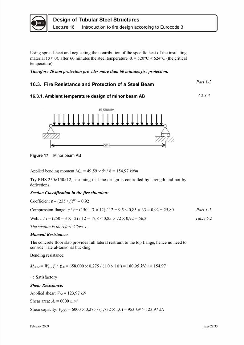
16.3.1. 2mbient tem!erature design of minor beam 2% 4.2.3.3
Figure 1' +inor 4eam :>
0pplied bending moment M Ed J 4(95( × 52 ' J 1549(& 'Nm
Tr ) S 25* ×15* ×129 assuming that the design is controlled b strength and not bdeflections.
Section Classification in the fire situation:
Coefficient ε J 235 f 6*95 J *9(2
Compression flangeH % t J 15* 3 × 126 12 J (95 *9'5 × 33 × *9(2 J 259'* Part 1-1
ebH % t J 25* 3 × 126 12 J 1&9' *9'5 × &2 × *9(2 J 5"93 Table *.2
T e se%ti+n is t eref+re Class 1.
%oment Resistance:
The concrete floor slab provides full lateral restraint to the top flange9 hence no need toconsider lateral+torsional buc,ling.
Bending resistanceH
M pl."d J pl, f γ M * J "5'.*** × *92&5 19*× 1* 36 J 1'*9(5 'Nm R 1549(&
⇒ Satisfactor
Shear Resistance:
0pplied shearH / Ed J 1239(& 'N
Shear areaH A9 J "*** mm2
Shear capacit H / pl,"d J "*** × *92&5 19&32× 19*6 J (53 'N R 1239(& 'N
Februar 2**( page 2' 33

8/16/2019 Lecture 16 - Text
http://slidepdf.com/reader/full/lecture-16-text 29/33
Design of Tubular Steel StructuresLecture 16 Introduction to fire design according to Eurocode 3
⇒ Satisfactor
16.3.". Fire resistance of minor beam 2%
Design Loading in Fire:
Combination factor ψ 191 J *95 Part 1-2
esign loading in fireH M fi,d J 19( Q *95 × 39'6 " × 5 2 ' J &1925 'Nm 2.4.2 (1)
Design Resistance in Fire:
For a Class 1 beam 7ith a uniform temperature distributionH
esign resistance in fire at time t J *H
M fi,t,"d J M fi,θ ,"d κ 1 κ 2 4.2.3.3
For beam supporting concrete slabH
κ 1 J *9& and κ 2 J 19*
M fi,*9 "d J "5'.*** × 2&5 *9&× 19*6 J 25'95 'Nm
Critical Temperature:
egree of utiliEationH µ * J &1925 25'95 J *92&"
Critical temperatureH θ %r J "&" 8C 4.2.4 (2)+r 4.2.4
Fire Resistance Time: Table 4.1
The change of steel temperature in time ∆t isH
∆θ a,t J 1 %a ρ a66 Am / 6 net,d ∆t
here for 3+sided e$posure6H
Section factorH
Am / J surface area of member volume of member J *9"5 *9**'41 J &293 m+1
esign value of net heat flu$ per unit area net,d is determined for the Standard Fire9using ε f J 19* and ε m J *9&.
B calculation using spreadsheetH
For t = 5 seconds the time taken for the steel to reach its critical temperature is"& minutes and ' seconds!
16.3.3. Fire !rotection of minor beam 2%
e re=uire "* minutes fire protection for the minor beam.Tr encasing 7ith 1* mm of h pothetical materialH
Februar 2**( page 2( 33

8/16/2019 Lecture 16 - Text
http://slidepdf.com/reader/full/lecture-16-text 30/33
Design of Tubular Steel StructuresLecture 16 Introduction to fire design according to Eurocode 3
Temperature increase of steel member in time ∆t isH
∆θ a,t J λ p d p %a ρ a66 A p L6 O1 1 Qφ 36P θ g,t +θ a,t 6 ∆ + eφ 1* + 16∆θ g,t 4.2.*.2
but ∆θ a,t R *.
hereH
Thic,ness d p J 1* mmensit ρ p J 1** 'g m3
Specific heat % p J 1&** 5 'g67 Thermal conductivit λ p J *92&& m67 Section factorH A p / J Am / J &293 m+1
Table 4.3
as temperature θ g,t is determined for the standard fire.
-sing spreadsheetH
0fter "* minutes the steel temperature θ a J "5*8C "&" 8C the critical temperature6. 4.2.*.2
Therefore 1* mm thic,ness of insulation provides more than "* minutes fire protection.
16.#. Fire -esistance and rotection of a Steel Column Part 1-2
4.2.3.2
Figure 1( !o'umn 9
Februar 2**( page 3* 33

8/16/2019 Lecture 16 - Text
http://slidepdf.com/reader/full/lecture-16-text 31/33
Design of Tubular Steel StructuresLecture 16 Introduction to fire design according to Eurocode 3
16.#.1. 2mbient tem!erature design of column 4
0$ial compression9 N Ed J ((19' 'N
SectionH ) S 15* ×15*×12
Section Classification in the fire situation: Part 1-1
Coefficient ε J 235 f 6*95 J *9(2 Table *.2
% t J 15* 3 × 126 12 J (95 33 × *9(2 × *9'5 J 259'1
The section is therefore Class 1.
Compression Resistance:
Slenderness λ J 395 *9*544 J "493
λ 1 J '"9'
ormalised slenderness J λ λ 1 J *9&4
)eduction factor curve c for cold formed sections69 χ J *9&*
β A J 1 for Class 1 sections
γ M 1 J 19*
Buc,ling resistance N b."d J χ β A A f γ M 1 J 115& 'N R ((19' 'N
⇒ Satisfactor
16.#.". Fire resistance of steel column 4
Figure 1* >uc 'ing 'engt* ('o-est store )
Design Loading in Fire: Part 1-2
esign loading in fireH N fi,d J 19( Q *95 × 39'6 5 × " × 4 J 45" 'N 2.4.2 (1)
Februar 2**( page 31 33

8/16/2019 Lecture 16 - Text
http://slidepdf.com/reader/full/lecture-16-text 32/33
Design of Tubular Steel StructuresLecture 16 Introduction to fire design according to Eurocode 3
Design Resistance in Fire:
Buc,ling resistance in fireH N b,fi,t,"d J χ fi A ' ,θ max f γ M,fi
ffective length factor J *9& for lo7est store 7ith pinned base. ;ntermediate store7ould have *95.
Slenderness λ J 45
F;)ST ;T )0T;%
0ssume that λ 1 in the fire situation J 0,85 × '"9' J &39&' 4.2.3.2
ormalised slenderness in the fire situation J λ λ 1 J *9"1
)eduction factor in fire9 χ fi J *9"&
N b,fi, *9 "d J *9"& × "1** × 1 × *92&5 19* J 1124 'N
Critical Temperature:
egree of utiliEation9 µ * J 45" 1124 J *94*" Part 1-2
Critical temperature θ %r J "1&8C 4.2.4 (2) +r
7 E J *92&( Table 4.1
7 f J *921*
*921* *92&(6*95 J *9'"' Part 1-2
Table 3.1S C% ;T )0T;%
λ 1 in the fire situation J *9'"' × '"9' J &5934
λ λ 1 J 45 &5934 J *95(&
)eduction factor in fire χ fi J *9"&( Part 1-24.2.3.2 (2)
N b,fi, *9 "d J *9"&( × "1** × 1 × *92&5 1 J 113( 'N
egree of utiliEation9 µ * J 45" 113( J *94**
Critical temperature θ %r J "2*8C U "1&8C
oteH or,ing in the load domain9 that means calculating the load bearing capacit inthe fire situation after a certain re=uired time9 e.g. 3* minutes9 7ould not impl aniteration.
Fire Resistance Time:
The change of steel temperature in time ∆t isH
∆θ a,t J 1 %a ρ a66 Am / 6 net,d ∆t
here for 4+sided e$posure6H
Section factorH Am / J surface area of member volume of member J ((9'3 m+1
Februar 2**( page 32 33

8/16/2019 Lecture 16 - Text
http://slidepdf.com/reader/full/lecture-16-text 33/33
Design of Tubular Steel StructuresLecture 16 Introduction to fire design according to Eurocode 3
B calculation using spreadsheetH
For t = 5 seconds the time taken for the steel to reach its critical temperature is1( minutes and 1" seconds!
1'. -eferencesO1P 1((1+1H urocode 1H Basis of esign and 0ctions on Structures. /art 1H Basis of esign.
O2P 1((1+1+2H urocode 1H Basis of esign and 0ctions on Structures. /art 1.2H 0ctions onStructures $posed to Fire.
O3P 1((3+1+1H urocode 3H esign of Steel Structures. /art 1.1H eneral )ulesH eneral )ules and)ules for Buildings.
O4P 1((3+1+2H urocode 3H esign of Steel Structures. /art 1.2H eneral )ulesH Structural Fireesign.
O5P 1((4+1+1H urocode 4H esign of Composite Steel and Concrete Structures. /art 1.1H eneral)ulesH eneral )ules and )ules for Buildings.
O"P 1((4+1+2H urocode 4H esign of Composite Steel and Concrete Structures. /art 1.2H eneral)ulesH Structural Fire esign.
O&P CCS 1('56. esign #anual on the uropean )ecommendations for the Fire Safet of SteelStructures9 uropean Convention for Constructional Steel7or,9 Brussels9 Belgium.