lecture-2 microwave engineering instructor: athar hanif
TRANSCRIPT

Lecture-2
Microwave EngineeringInstructor: Athar Hanif

1.2-Dimensions and Units
To understand the upper frequency limit, beyond which conventional circuit theory can no longer be applied to analyze an electric system, we should recall the representation of an electromagnetic wave.

1.2-Dimensions and Units

1.2-Dimensions and Units
Propagation constant/Phase constant represents the change in phase per meter along the path travelled by the wave at any instant and is equal to the wave number of the wave.

1.2-Dimensions and Units
Intrinsic impedance: the ratio between electric and magnetic field components.
TEM Waves: field components are perpendicular to each other and both are perpendicular to the direction of propagation.

1.2-Dimensions and Units
TE Waves: in this magnetic field component is perpendicular to the direction of propagation.
TM Waves: in this electric field component is perpendicular to the direction of propagation.

1.2-Dimensions and Units
The phase velocity of the TEM wave can be found as
Example1.1:
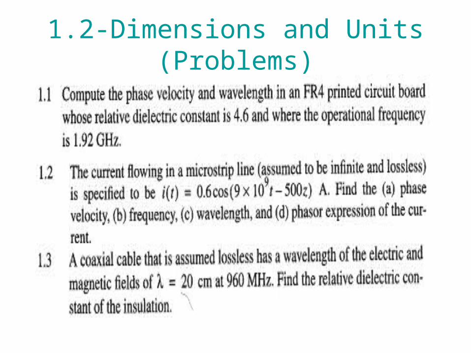
1.2-Dimensions and Units (Problems)

1.2-Dimensions and Units (Problems)
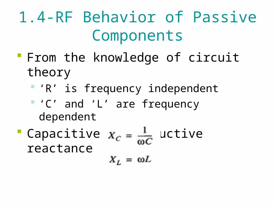
1.4-RF Behavior of Passive Components
From the knowledge of circuit theory ‘R’ is frequency independent ‘C’ and ‘L’ are frequency dependent
Capacitive and inductive reactance

1.4-RF Behavior of Passive Components
For; C=1pF and L=1nH XC=
XL=
For the low frequency; R, C and L are created by wires, plates and coils respectively
For the RF/Microwave frequency, single straight wire or a copper segment of a

1.4-RF Behavior of Passive Components
printed circuit board (PCB) layout has frequency dependent resistance and inductance

1.4-RF Behavior of Passive Components
DC excitation AC excitation
Skin effect
For high frequency condition(f≥500MHz)
xx
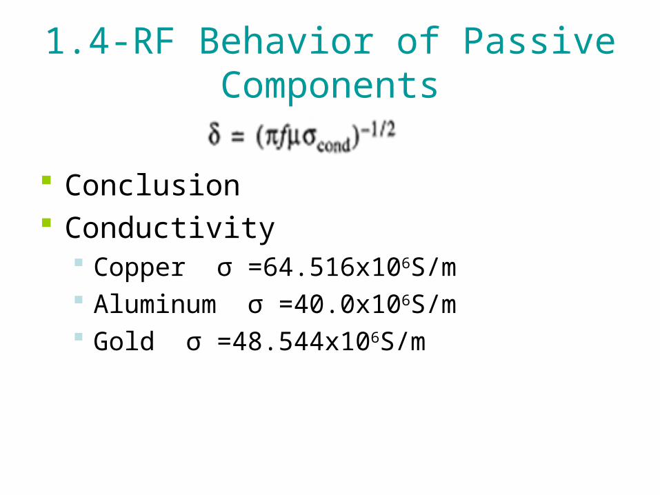
1.4-RF Behavior of Passive Components
Conclusion Conductivity
Copper σ =64.516х106S/m Aluminum σ =40.0х106S/m Gold σ =48.544х106S/m
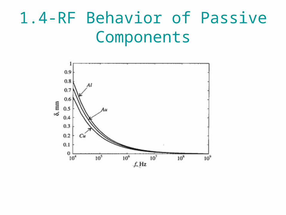
1.4-RF Behavior of Passive Components

1.4-RF Behavior of Passive Components
• From this we conclude that resistance increases inversely proportional to the cross-sectional skin area
1.4-RF Behavior of Passive Components
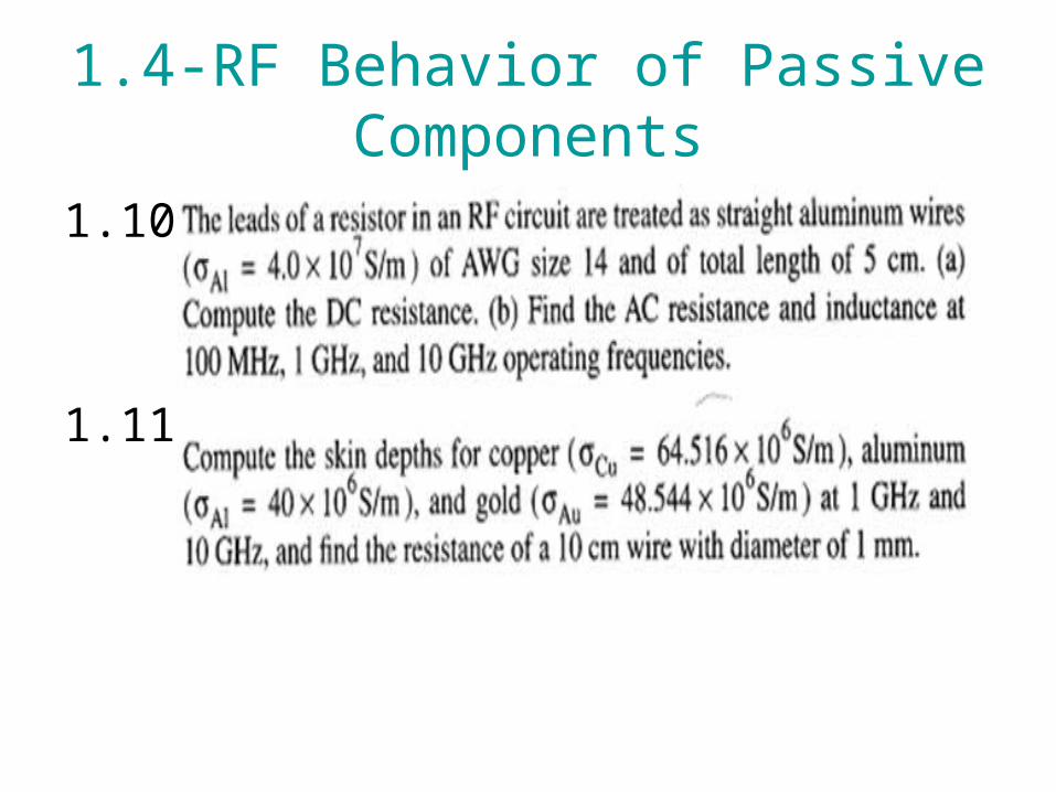
1.10-
1.11-

1.4-AWG System
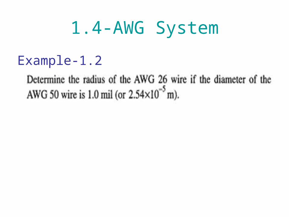
Diameter of the wire is determined by its AWG value
General rule: the diameter of the wire is doubles every six wire gauges starting with 1mil for a AWG 50 wire
1.4-AWG System
Example-1.2

1.4.1-High Frequency Resistors
• c

1.4.1-High Frequency Resistors
Electric equivalent circuit representation of the resistor
1.4.1-High Frequency Resistors
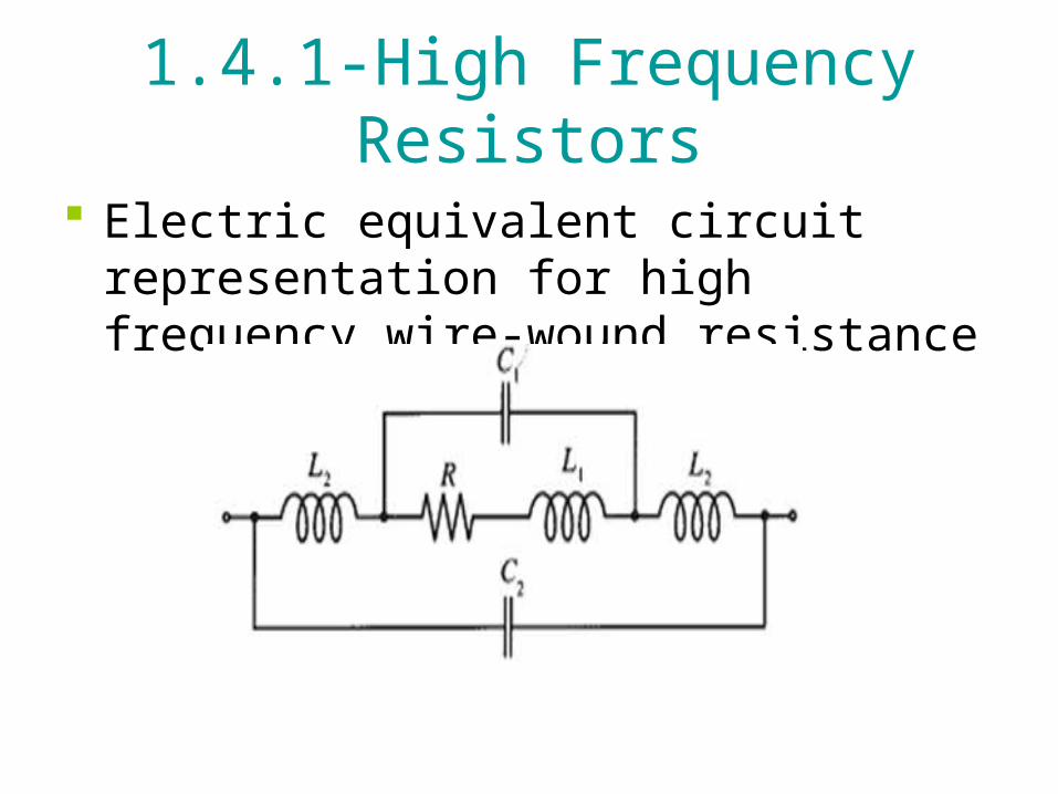
Electric equivalent circuit representation for high frequency wire-wound resistance

Example 1.3

Example 1.3

1.4.2-High Frequency Capacitors
In RF/Microwave circuits chip capacitors find widespread applications Tuning of filters Matching networks Biasing active components
1.4.2-High Frequency Capacitors
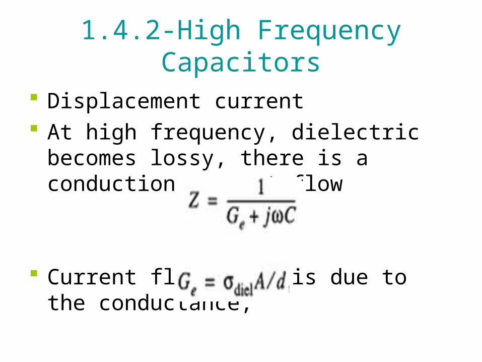
Displacement current At high frequency, dielectric becomes
lossy, there is a conduction current flow
Current flow at DC is due to the conductance,

1.4.2-High Frequency Capacitors
Loss tangent is defined by the angle between the capacitor’s impedance vector and the negative reactive axis

1.4.2-High Frequency Capacitors

1.4.2-High Frequency Capacitors
• Electric equivalent circuit for a high frequency capacitor

Example 1.4
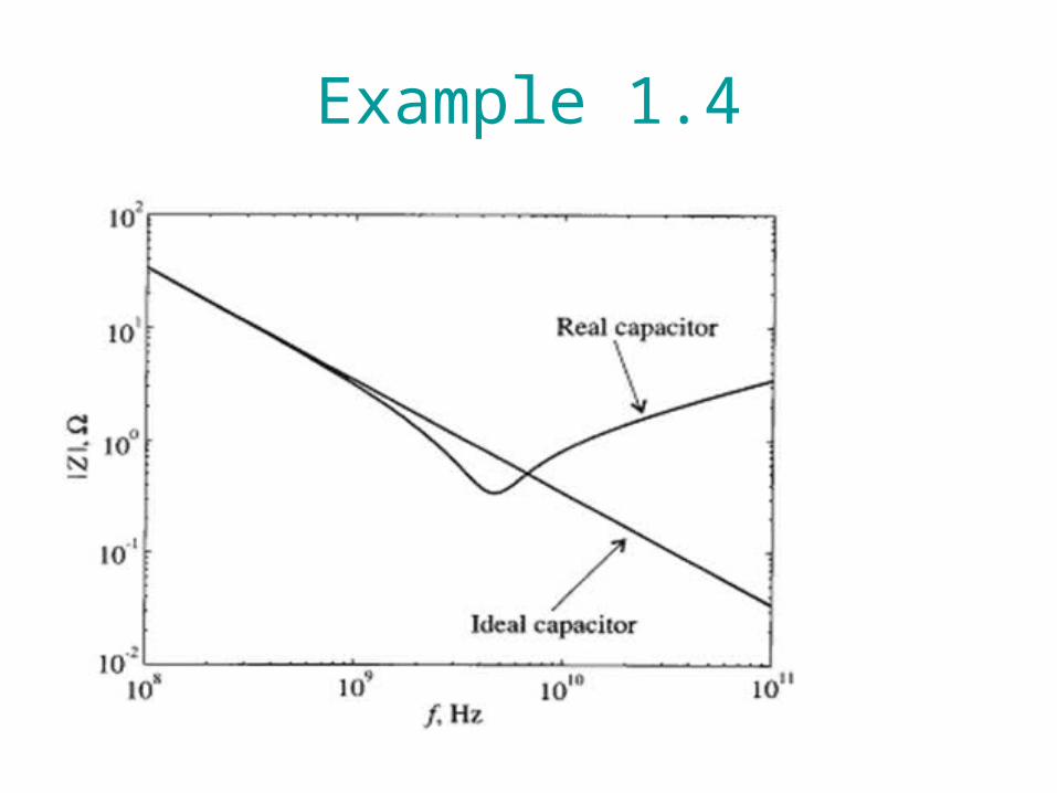
Example 1.4

Loss Tangent
Loss tangent can also be defined as the ratio of an equivalent series resistance to the capacitor’s reactance
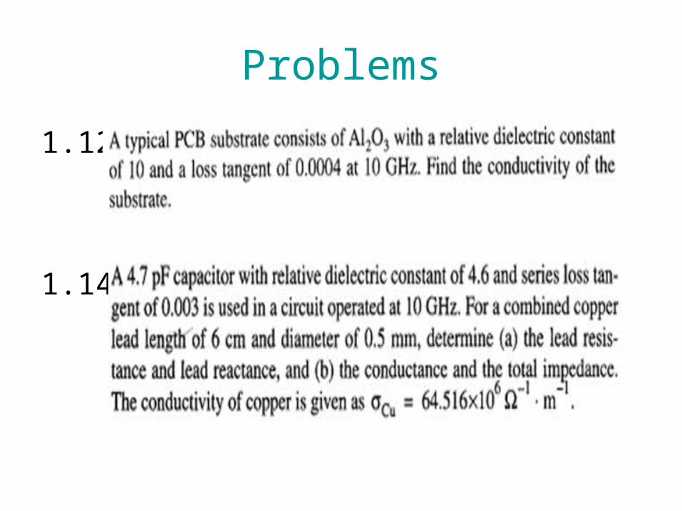
Problems
1.12
1.14

Problems
1.15
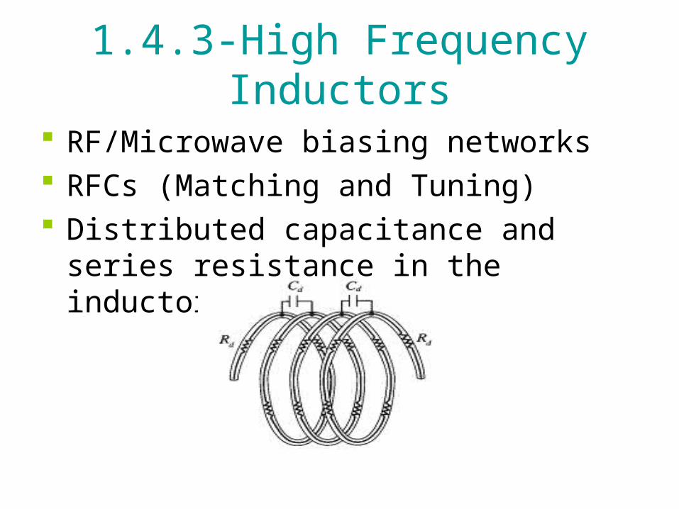
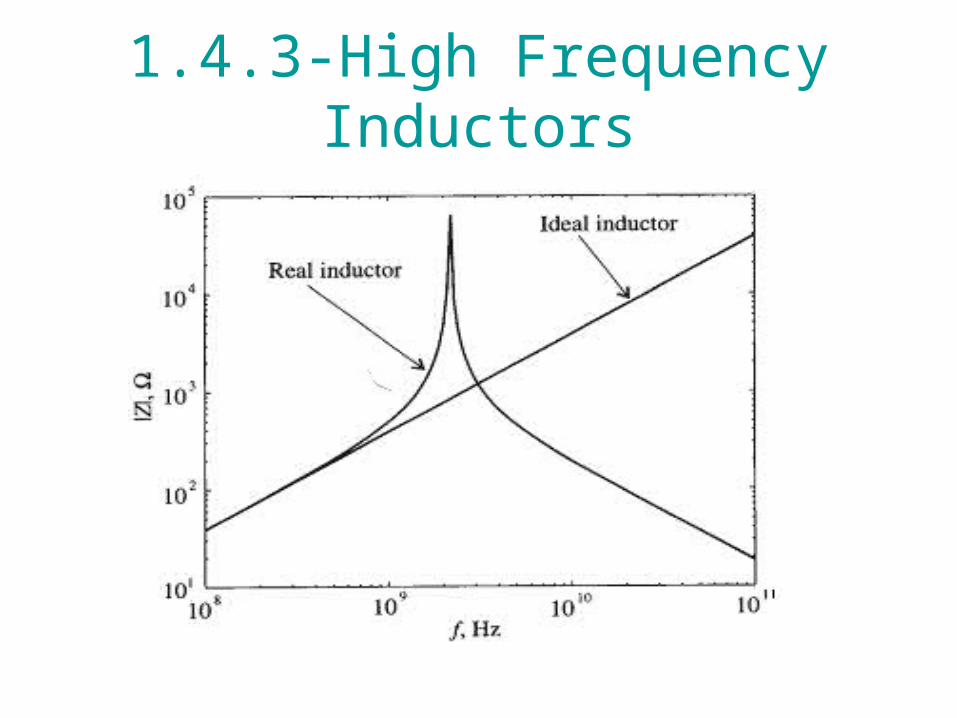
1.4.3-High Frequency Inductors
RF/Microwave biasing networks RFCs (Matching and Tuning) Distributed capacitance and series
resistance in the inductor coil
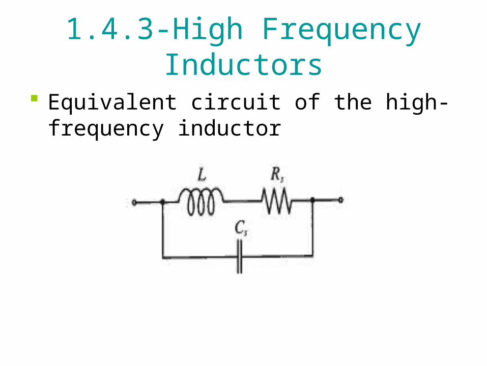
1.4.3-High Frequency Inductors
Equivalent circuit of the high-frequency inductor

1.4.3-High Frequency Inductors
Example 1.5:
1.4.3-High Frequency Inductors
1.4.3-High Frequency Inductors
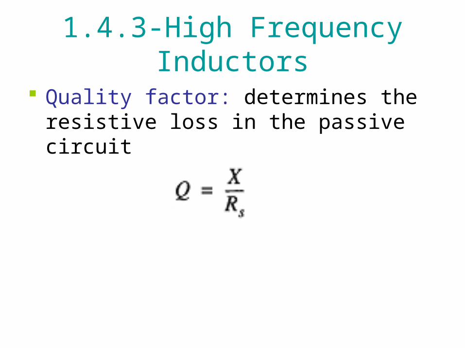
Quality factor: determines the resistive loss in the passive circuit
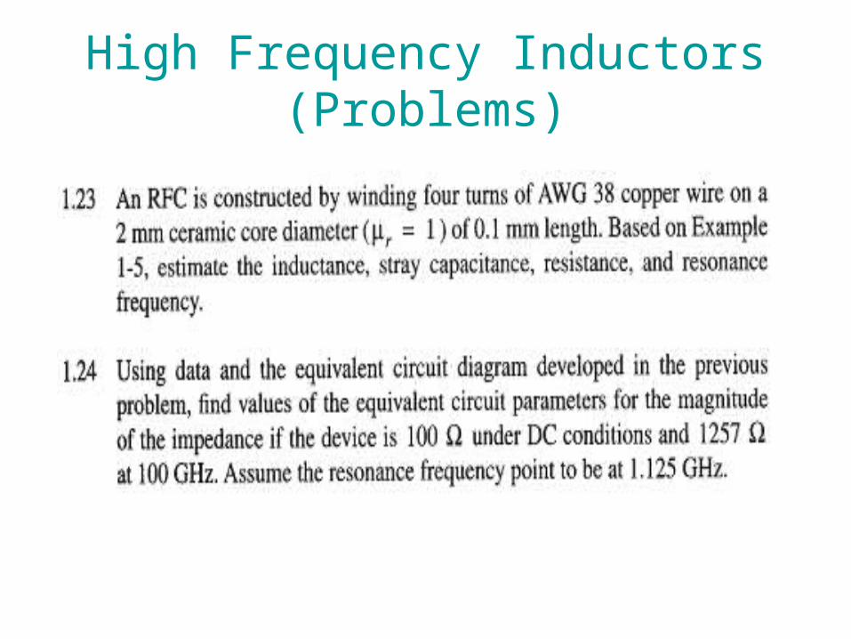
High Frequency Inductors (Problems)