lecture 7 - mcgill cimlanger/557/7-slides.pdf · e.g. fire, explosions, smoke, fog, ... ......
TRANSCRIPT

lecture 7
- graphics pipeline (overview)
- hidden surface removal
- object vs image order- back face culling- depth buffer (z buffer)- painters algorithm- ray casting
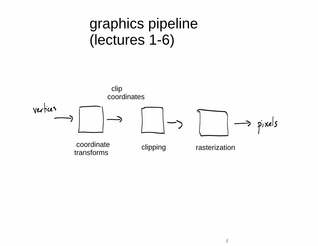
graphics pipeline(lectures 1-6)
clipping coordinatetransforms
clipcoordinates
rasterization
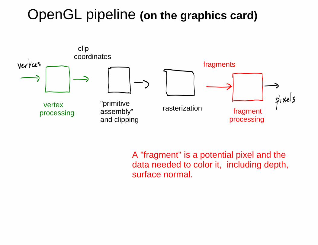
OpenGL pipeline (on the graphics card)
A "fragment" is a potential pixel and thedata needed to color it, including depth,surface normal.
"primitiveassembly"and clipping
vertexprocessing
clipcoordinates
rasterization fragmentprocessing
fragments

"primitiveassembly"and clipping
vertexprocessing
clipcoordinates
rasterization fragmentprocessing
fragments
"fixed function"
"vertex shader"(programmable)
OpenGL1.0
ModernOpenGL
"fixed function"
"fragment shader"(programmable)
hidden hidden
hidden hidden
classic vs. modern OpenGL

Vertex Processing
Suppose you want to make a water wave animation.The surface is a set of triangles, made fromvertices { (x, height(x,z,t)), z }
height() is a little program -- a "vertex shader"e.g. a sine wave.
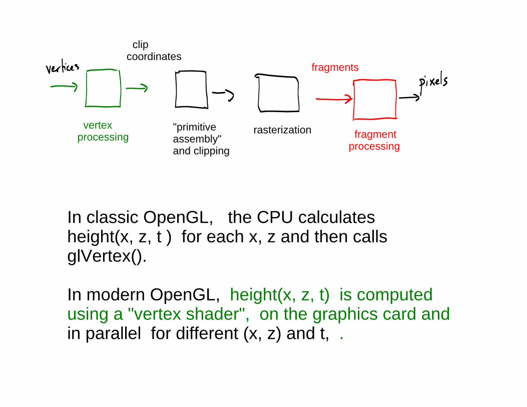
In classic OpenGL, the CPU calculatesheight(x, z, t ) for each x, z and then callsglVertex().
In modern OpenGL, height(x, z, t) is computedusing a "vertex shader", on the graphics card andin parallel for different (x, z) and t, .
"primitiveassembly"and clipping
vertexprocessing
clipcoordinates
rasterization fragmentprocessing
fragments

"Particle systems" (vertex processing)e.g. Fire, explosions, smoke, fog, ...
Calculate geometric transforms on vertices/primitives.Calculate (time varying) "color" of vertices, too!
Careful: no pixels yet !
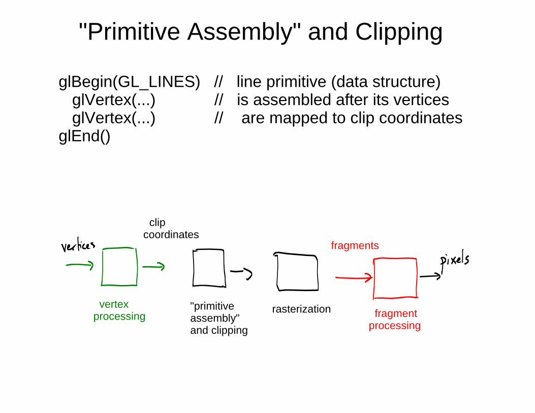
"Primitive Assembly" and Clipping
glBegin(GL_LINES) // line primitive (data structure) glVertex(...) // is assembled after its vertices glVertex(...) // are mapped to clip coordinatesglEnd()
"primitiveassembly"and clipping
vertexprocessing
clipcoordinates
rasterization fragmentprocessing
fragments

Fragment processing
A fragment is a potential pixel. It has an (x,y) coordinate,and information about depth, color, ....
We will discuss fragment processing later in the course.
"primitiveassembly"and clipping
vertexprocessing
clipcoordinates
rasterization fragmentprocessing
fragments

Part 2 of the course starts here.
lecture 7
- graphics pipeline (overview)
- hidden surface removal:
the problem of deciding which polygon/object is visible at each pixel.
- object vs image order- back face culling- depth buffer (z buffer)- painters algorithm- ray casting

"object order" methods
for each object for each pixel decide if object is visible at that pixel
"image order" methods
for each pixel for each object
decide if object is visible at that pixel
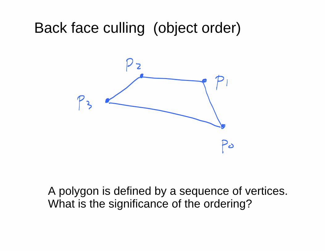
Back face culling (object order)
A polygon is defined by a sequence of vertices.What is the significance of the ordering?

In OpenGL, the front face of a polygon is defined(by default) as the side where vertices would beordered counter clockwise, i.e. if a viewer were onthat side.
glFrontFace(GL_CCW) // default
glFrontFace(GL_CW) // override default

Choose ordering of vertices for each face as shownso that front faces are seen by a viewer.

In this example, the vertices of each wall ofthe room have opposite ordering as onprevious slide. This allows a viewer that isinside the room to see the walls.

The normal comes out of the front face.(The front face has an "outward pointing normal"and a back face has an "inward pointing normal". )
[WARNING: In OpenGL, surface normals alsocan be explicitly defined defined at vertices. (Wewill see later why.) But these normals havenothing to do with front and back faces as justdefined.]

"Back Face Culling"= don't draw the back faces!
For a solid object, back faces shouldn't be visible becausethey are hidden by the front faces.

If back face culling is "enabled", then the back faceis not drawn.
In A1, we used glDisable(GL_CULL_FACE).
glEnable(GL_CULL_FACE)

When is a polygon back vs. front face ?
In camera coordinates, it is subtle. You can't just lookat the sign of the z coordinate.

Use the sign of the dot product of the outwardfacing normal and the vector from the viewerto any vertex on the polygon.

vertexprocessing
clipcoordinates
rasterization fragmentprocessing
fragments
Q: Where is back face culling done ?
A: In OpenGL it is done by rasterizer. But in principle, it can be done before entering pipeline!
"primitiveassembly" andclipping
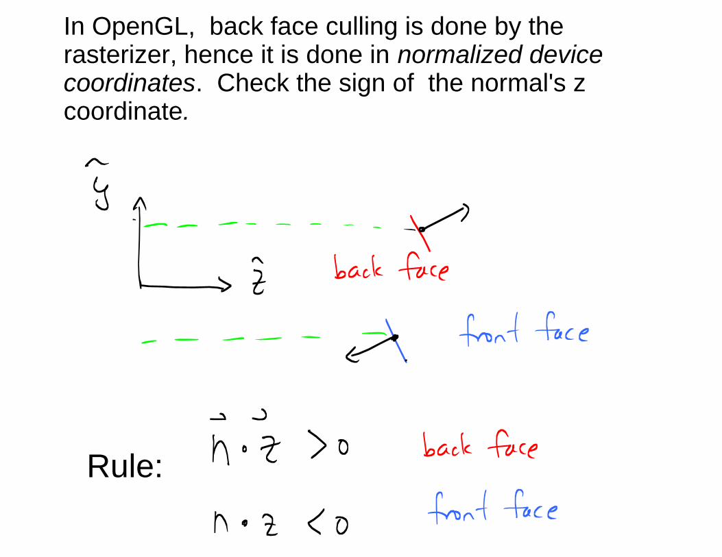
In OpenGL, back face culling is done by therasterizer, hence it is done in normalized devicecoordinates. Check the sign of the normal's zcoordinate.
Rule:

Depth Buffer (z buffer)
image buffer/ z bufferframe buffer
(not same asmonitor screen)
glEnable(GL_DEPTH_TEST)

for each polygon P: for each pixel (x,y) in P's image projection
if P's depth at (x,y) is less than zbuffer(x,y)
then
update zbuffer(x,y) compute color of P at (x,y) and replace the current color with the new color
Hidden surface removalalgorithm (depth buffer) Catmull 1974

for each pixel (x,y): // initializationzbuffer(x,y) = 1
RGB(x,y) = background color
for each polygon: for each pixel (x,y) in the image projection of polygon z := Ax + By + C
// equation of polygon's plane in SCREEN coordinates
if z < zbuffer(x,y) :zbuffer(x,y) := zcompute RGB(x,y)
Pseudocode...

"primitiveassembly"and clipping
vertexprocessing
clipcoordinates
rasterization fragmentprocessing
fragments
Q: Where is the depth buffer algorithm here ?
A: It is done by the rasterizer. If polygon fails the depth test at (x,y), then fragment never
gets generated.
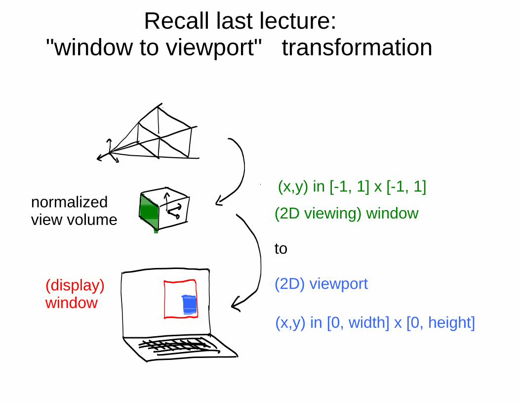
normalizedview volume (2D viewing) window
to
(2D) viewport(display)window
Recall last lecture:"window to viewport" transformation
(x,y) in [0, width] x [0, height]
(x,y) in [-1, 1] x [-1, 1]

There is also a depth component to the mapping.
(x,y, z) in [-1, 1] x [-1, 1] x [-1, 1]
(x,y, z) in [0, width] x [0, height] x [0, 1]

Depth buffer typically holds fixed precision (e.g. 24bits),not float.
i.e. z in [ 0, 1] partitioned into bins of size 1 / 2^24.
Q: Why ?
A: Floating point is useful for representing tiny and huge numbers, but that's in appropriate here.

Recall glFrustum( __ , __ , __ , __ , near, far)
where near and far are float or double.
Q: Why not set:
near = .00000...1
far = 2^ 1023 ?
A: You would divide the huge [near, far] interval into 2^24 depth intervals/bins. Most points will fall in one of these intervals --> useless because they all have same
(quantized/rounded) depth

Painter's Algorithm [Newell et al 1972]
(older than depth buffer)
Draw farthest polygons first.
http://en.wikipedia.org/wiki/Painter's_algorithm

Painter's Algorithm
Sort polygons in depth. (Arbitrarily) use the farthest vertexin each polygon as the sorting key.
e.g 26 polygons [ A, B, C, .... P, Q, .... , Z ]
Then draw polygons from "farthest" to "nearest"(back to front).
However, that doesn't always work. Why not ?
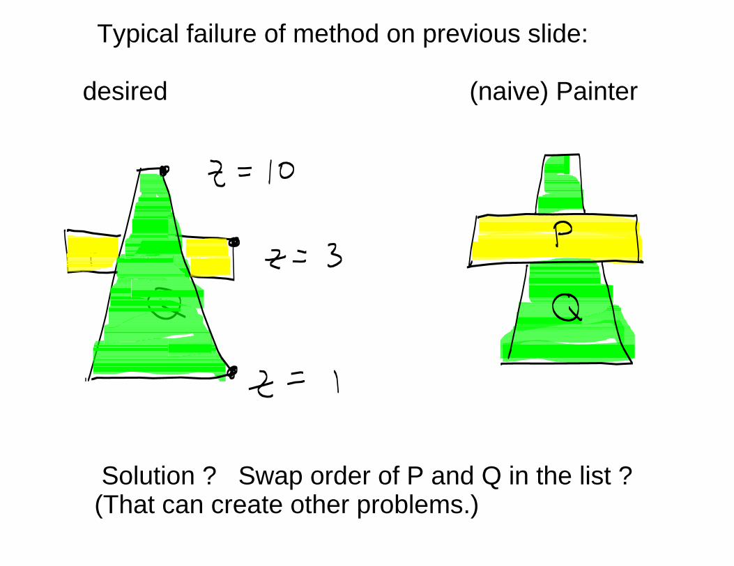
Typical failure of method on previous slide:
desired (naive) Painter
Solution ? Swap order of P and Q in the list ?(That can create other problems.)

Classic failure case (cardboard box):
For this example, there does not exist a'correct' ordering for drawing thepolygons.

A related common example of failure
Problem Solution (cut Q into Q1, Q2)

Classic failure case (cardboard box):
Same solution can be applied here.(Cut the polygons.)
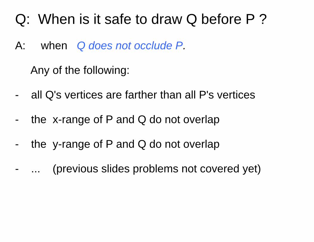
Q: When is it safe to draw Q before P ?
A: when Q does not occlude P.
Any of the following:
- all Q's vertices are farther than all P's vertices
- the x-range of P and Q do not overlap
- the y-range of P and Q do not overlap
- ... (previous slides problems not covered yet)
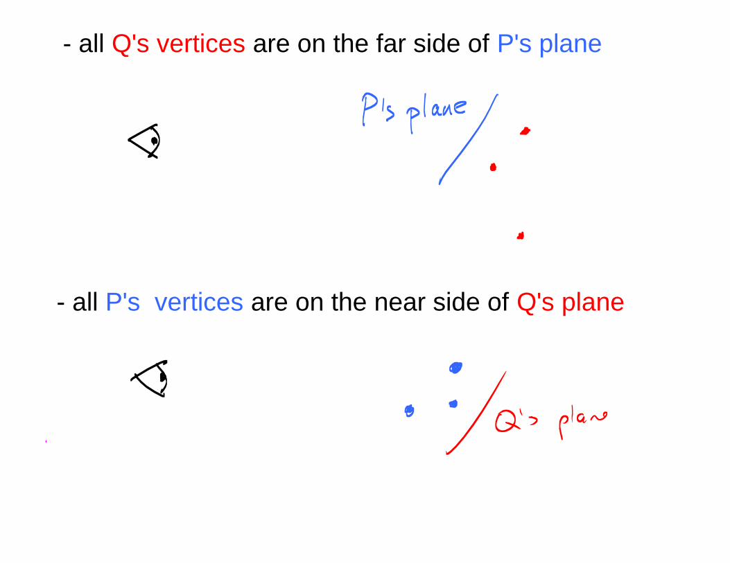
- all P's vertices are on the near side of Q's plane
- all Q's vertices are on the far side of P's plane

SLIDE ADDED (morning after)
I have not given the full Painter's Algorithm.
I have not shown how to deal with every case.
The full algorithm has more details that I want tocover.
But I think you get the main ideas. And itsenough for me to motivate BST trees nextlecture.

"primitiveassembly"and clipping
vertexprocessing
clipcoordinates
rasterization fragmentprocessing
fragments
Q: Where is the painter's algorithm here ?
A: The decision to draw (or cut) a polygon is made by the CPU prior to putting vertices into the graphics pipeline.
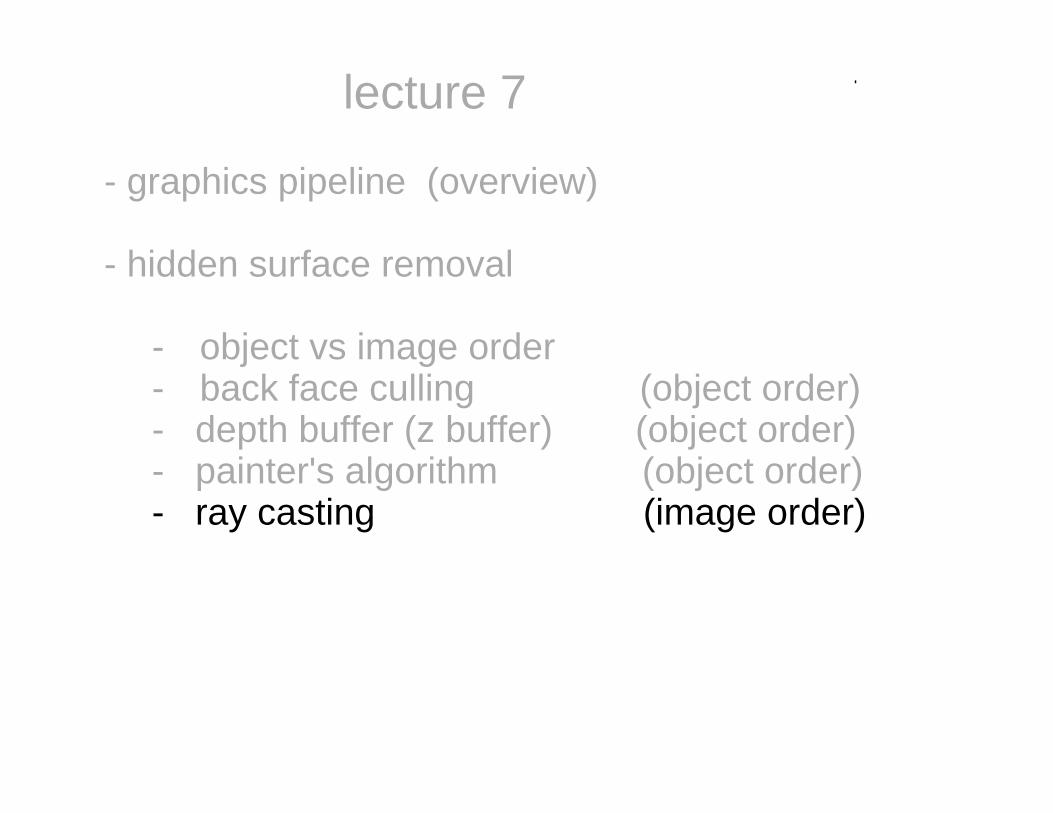
lecture 7
- graphics pipeline (overview)
- hidden surface removal
- object vs image order- back face culling (object order)- depth buffer (z buffer) (object order)- painter's algorithm (object order)- ray casting (image order)

for each pixel (x,y) {
for each polygon{
check if the pixel lies in the image of that polygon and if the depth is smallest seen so far at that pixel. } draw the color of the nearest polygon at that pixel}
Ray Casting (an image order method)

for each pixel (x,y){ // screen coordinateszMin = 1 // initialized to max value
for each polygon{ if (x,y) lies in image projection of this polygon{
z = Ax + By + C // screen coordinates if z < zMin zMin := z pixel(x,y).poly = polygon
} } RGB(x,y) = ...?... // only draw once per pixel}
Ray Casting

No z-buffer needed.
For each pixel, only choose its color once.
Need to determine if a pixel lies in apolygon.(Details omitted.)

More general ray casting (used next lecture)
Does ray from p0 through p1 intersect thepolygon?
Typically p0 is the camera position. But notnecessarily...

Trick: project the polygon and theintersection point with plane orthographicallyinto a canonical plane and use the 2D "pointin polygon" solution.
How to decide if the intersection point lies in thepolygon?

Does ray intersect this quadric ?

[ x, y, z, 1 ] Q [ x, y, z, 1 ]^T = 0
(x(t), y(t), z(t) ) = p0 + (p1 - p0) t
Substitute the ray into the quadric gives asecond order equation:
t^2 + t + c = 0
Solve for t.
Gives two solutions. What are the possibilities ?

Two real roots.If at least one is positive,then take the smallerpositive one.
Two real roots (identical).
Both roots are complex.

Announcement
A1 was posted on Friday. It is due next Monday.
Example of solution (executable):http://cim.mcgill.ca/~fmannan/comp557/index.html
TA office hours this week.
DISCUSSION BOARD SETTINGS.Please uncheck: "Include original post in reply"