lecture notes on - cet.edu.in lecture notes-ilovepdf... · the transducer, which generates the...
TRANSCRIPT

MODERN MANUFACTURING PROCESSES (PEME 5306)
1DR P.K.Parida, CET, BBSR
LECTURE NOTES ON
Modern Manufacturing Process
PREPARED BY
Dr PRAMOD KUMAR PARIDA
ASSISTANT PROFESSOR
DEPARTMENT OF MECHANICAL ENGINEERING
COLLEGE OF ENGINEERING & TECHNOLOGY (BPUT)
BHUBANRSWAR

MODERN MANUFACTURING PROCESSES (PEME 5306)
2DR P.K.Parida, CET, BBSR
SyllabusModule I (12 hours) ULTRASONIC MACHINING (USM): Introduction, equipment, tool materials & tool size, abrasive slurry, cutting tool system design:- Effect of parameters on Material removal rate, tool wear, Accuracy, surface finish, applications, advantages & Disadvantages of USM. ABRASIVE JET MACHINING (AJM): Introduction, Equipment, Variables in AJM: Carrier Gas, Type of abrasive work material, stand off distance (SOD), nozzle design, shape of cut. Process characteristics-Material removal rate, Nozzle wear, Accuracy & surface finish. Applications, advantages & Disadvantages of AJM.Water Jet Machining: Principle, Equipment, Operation, Application, Advantages and limitations of Water Jet machining. ELECTROCHEMICAL MACHINING (ECM): Introduction, study of ECM machine, elements of ECM process: ECM Process characteristics – Material removal rate, Accuracy, surface finish, Applications, Electrochemical turning, Grinding, Honing, deburring, Advantages, Limitations. CHEMICAL MACHINING (CHM): Introduction, elements of process, chemical blanking process, process characteristics of CHM: material removal rate, accuracy, surface finish, Hydrogen embrittlement, advantages & application of CHM. Module II (13 hours)ELECTRICAL DISCHARGE MACHINING (EDM): Introduction, mechanism of metal removal, dielectric fluid, spark generator, EDM tools (electrodes) Electrode feed control, EDM process characteristics: metal removal rate, accuracy, surface finish, Heat Affected Zone. Machine tool selection, Application, electrical discharge grinding, wire EDM. PLASMA ARC MACHINING (PAM): Introduction, equipment, non-thermal generation of plasma, selection of gas, Mechanism of metal removal, PAM parameters, process characteristics. Applications, Advantages and limitations.LASER BEAM MACHINING (LBM): Introduction, equipment of LBM mechanism of metal removal, LBM parameters, Process characteristics, Applications, Advantages & limitations.ELECTRON BEAM MACHINING (EBM): Principles, equipment, operations, applications, advantages and limitation of EBM. Module III (11 hours) Introduction to Surface engineering, High speed machining and grinding: Application of advanced coatings in high performance modern cutting tools and high performance super-abrasive grinding wheels, Micro and nano machining of glasses and ceramics. Theory and application of chemical processing: Chemical Machining, Aching of semi conductors, Coating and Electroless forming, PVD and CVD; Introduction to Reverse Engineering, Concurrent Engineering and Rapid prototyping: Text Books:
1. Modern machining process, Pandey and Shan, Tata McGraw Hill 2000 2. Manufacturing Engg. & Technology, Kalpakjian , Pearson Education 3. Manufacturing Science, A.Ghosh& A.K. Mallik, EWP
Reference Books 1. Metals Handbook: Machining Volume 16, Joseph R. Davis (Editor), American Society of
Metals. 2. Surface Wear Analysis, Treatment & Prevention - ASM International, Materials Park, OH,
U.S.A., 1st Ed. 1995 3. Production Technology, HMT, Tata McGraw Hill. 2001 4. Modern Machining Process, Aditya. 2002 5. Non-Conventional Machining, P.K.Mishra, The Institution of Engineers (India) Test book
series, Narosa Publishing House – 2005. 6. Introduction to Rapid Prototyping, A Ghosh, North West Publication

MODERN MANUFACTURING PROCESSES (PEME 5306)
3DR P.K.Parida, CET, BBSR
COURSE OUTCOMESThe course is consists of all non-conventional manufacturing processes. It starts with classification of manufacturing processes and necessity of non-conventional manufacturing processes. This course dealt with details about the mechanism of material removal, sources of energy used for material removal, working principle, the set up or equipment and relative advantages and disadvantages. It gives a clear cut idea about the processes, its use in specific industrial application etc.
Module IModern or Non Traditional Manufacturing Processes
Modern or Non-traditional manufacturing processes is defined as a group
of processes that remove excess material by various techniques involving
mechanical, thermal, electrical or chemical energy or combinations of these
energies but do not use a sharp cutting tools as it needs to be used for
traditional manufacturing processes.
Extremely hard and brittle materials are difficult to machine by traditional
machining processes such as turning, drilling, shaping and milling. Non-
traditional machining processes, also called advanced manufacturing
processes, are employed where traditional machining processes are not
feasible, satisfactory or economical due to special reasons as outlined
below.
Very hard fragile materials difficult to clamp for traditional machining
When the workpiece is too flexible or slender
When the shape of the part is too complex
Several types of non-traditional machining processes have been developed
to meet extra required machining conditions. When these processes are

MODERN MANUFACTURING PROCESSES (PEME 5306)
4DR P.K.Parida, CET, BBSR
employed properly, they offer many advantages over non-traditional
machining processes. The common non-traditional machining processes
are described in this section.
Modern manufacturing processes are classified according to the type of
fundamental machining energy employed. A detail classification f the
machining process based on the type of energy used , the mechanism of
metal removal, the source of energy requirements etc is given below:
Classification of machining processes
Type of Energy
Mechanism of Metal Removal
Transfer Media
Energy source Processes
Mechanical Erosion High velocity particle
Pneumatic/Hydraulic pressure
AJM, USM, WJM
Shear Physical contact
Cutting tool Conventional machining
Electro chemical
Ion displacement
Electrolyte High current ECM, ECG
Chemical Ablative relation
Reactive environment
Corrosive agent CHM
Thermoelectric Fusion Hot gases Ionized material IBM, PAMElectrons High voltage EDM
Vaporization Radiation Amplified light LBMIon stream Ionized material PAM
AJM: Abrasive Jet Machining
CHM:Chemical machining
ECG: Electrochemical Grinding
ECM:Electrochemical Machining
EDM:Electro Discharge Machining

MODERN MANUFACTURING PROCESSES (PEME 5306)
5DR P.K.Parida, CET, BBSR
IBM: Ion Beam Machining
LBM: Laser Beam Machining
PAM:Plasma Arc Machining
USM:Ultrasonic Machining
WJM:Water Jet Machining
ULTRASONIC MACHINING (USM):
USM is mechanical material removal process or an abrasive process used
to erode holes or cavities on hard or brittle workpiece by using shaped
tools, high frequency mechanical motion and an abrasive slurry. USM
offers a solution to the expanding need for machining brittle materials such
as single crystals, glasses and polycrystalline ceramics, and increasing
complex operations to provide intricate shapes and workpiece profiles. It is
therefore used extensively in machining hard and brittle materials that are
difficult to machine by traditional manufacturing processes. The hard
particles in slurry are accelerated toward the surface of the workpiece by a
tool oscillating at a frequency up to 100 KHz - through repeated abrasions,
the tool machines a cavity of a cross section identical to its own. A
schematic representation of USM is shown in Figure 1.
Figure 1: Schematic of ultrasonic machine tool

MODERN MANUFACTURING PROCESSES (PEME 5306)
6DR P.K.Parida, CET, BBSR
USM is primarily targeted for the machining of hard and brittle
materials(dielectric or conductive) such as boron carbide, ceramics,
titanium carbides, rubies, quartz etc. USM is a versatile machining process
as far as properties of materials are concerned. This process is able to
effectively machine all materials whether they are electrically conductive or
insulator.
For an effective cutting operation, the following parameters need to be
carefully considered:
The machining tool must be selected to be highly wear resistant, such
as high-carbon steels.
The abrasives (25-60 m in dia.) in the (water-based, up to 40% solid
volume) slurry includes: Boron carbide, silicon carbide and aluminum
oxide.
Mechanisms of Material Removal in USM and its modeling
As has been mentioned earlier, USM is generally used for machining brittle
work material. Material removal primarily occurs due to the indentation of
the hard abrasive grits on the brittle work material. As the tool vibrates, it
leads to indentation of the abrasive grits. During indentation, due to
Hertzian contact stresses, cracks would develop just below the contact site,
then as indentation progresses the cracks would propagate due to increase
in stress and ultimately lead to brittle fracture of the work material under
each individual interaction site between the abrasive grits and the
workpiece. The tool material should be such that indentation by the
abrasive grits does not lead to brittle failure. Thus the tools are made of
tough, strong and ductile materials like steel, stainless steel and other
ductile metallic alloys. Other than this brittle failure of the work material due

MODERN MANUFACTURING PROCESSES (PEME 5306)
7DR P.K.Parida, CET, BBSR
to indentation some material removal may occur due to free flowing impact
of the abrasives against the work material and related solid-solid impact
erosion, but it is estimated to be rather insignificant. Thus, in the current
model, material removal would be assumed to take place only due to
impact of abrasives between tool and workpiece, followed by indentation
and brittle fracture of the workpiece. The model does consider the
deformation of the tool. In the current model, all the abrasives are
considered to be identical in shape and size. An abrasive particle is
considered to be spherical but with local spherical bulges as shown in Fig.
9.2.2. The abrasive particles are characterised by the average grit
diameter, dg. It is further assumed that the local spherical bulges have a
uniform diameter, db and which is related to the grit diameter by db = μdg2 .
Thus an abrasive is characterised by μ and dg.
Schematic representation of abrasive grit
During indentation by the abrasive grit onto the workpiece and the tool, the
local spherical bulges contact the surfaces and the indentation process is
characterised by db rather than by dg. Fig. 9.2.3 shows the interaction
between the abrasive grit and the workpiece and tool.

MODERN MANUFACTURING PROCESSES (PEME 5306)
8DR P.K.Parida, CET, BBSR
Interaction between grit and workpiece and tool
And then the indentation process starts and finally completes with an
indentation of δw and δt on the work and tool respectively.

MODERN MANUFACTURING PROCESSES (PEME 5306)
9DR P.K.Parida, CET, BBSR
The tool vibrates in a harmonic motion. Thus only during its first quarter of
its cycle it can derive an abrasive towards interaction with the tool and
workpiece as shown in Fig. below. Out of this quarter cycle, some part is
used to engage the tool with abrasive particle as shown in Fig. below. Thus
the time of indentation τ can be roughly estimated as
Interaction between grit and workpiece and tool to depict the workpiece and tool deformations

MODERN MANUFACTURING PROCESSES (PEME 5306)
10DR P.K.Parida, CET, BBSR

MODERN MANUFACTURING PROCESSES (PEME 5306)
11DR P.K.Parida, CET, BBSR
Process Parameters and their effects:

MODERN MANUFACTURING PROCESSES (PEME 5306)
12DR P.K.Parida, CET, BBSR
Effect of machining parameters on MRR
Equipment:
The basic mechanical structure of an USM is very similar to a drill press. However, it has additional features to carry out USM of brittle work material. The workpiece is mounted on a vice, which can be located at the desired position under the tool using a 2 axis table. The table can further be

MODERN MANUFACTURING PROCESSES (PEME 5306)
13DR P.K.Parida, CET, BBSR
lowered or raised to accommodate work of different thickness. The typical elements of an USM are (Fig.)
Slurry delivery and return system Feed mechanism to provide a downward feed force on the tool during
machining The transducer, which generates the ultrasonic vibration Version 2
ME, IIT Kharagpur The horn or concentrator, which mechanically amplifies the vibration
to the required amplitude of 15 – 50 μm and accommodates the tool at its tip.
Schematic view of an Ultrasonic Machine
The ultrasonic vibrations are produced by the transducer. The transducer is driven by suitable signal generator followed by power amplifier. The transducer for USM works on the following principle

MODERN MANUFACTURING PROCESSES (PEME 5306)
14DR P.K.Parida, CET, BBSR
• Piezoelectric effect
• Magnetostrictive effect
• Electrostrictive effect Magnetostrictive transducers are most popular and robust amongst all.
Fig. below shows a typical magnetostrictive transducer along with horn. The horn or concentrator is a wave-guide, which amplifies and concentrates the vibration to the tool from the transducer.
Working of horn as mechanical amplifier of amplitude of vibration

MODERN MANUFACTURING PROCESSES (PEME 5306)
15DR P.K.Parida, CET, BBSR
Different Horns used in USM
Applications
The beauty of USM is that it can make non round shapes in hard and brittle
materials. Ultrasonically machined non round-hole part is shown in Figure
2.
Figure 2: A non-round hole made by USM
Advantage of USM
USM processis a non-thermal, non-chemical, creates no changes in the
microstructures, chemical or physical properties of the workpiece and offers
virtually stress free machined surfaces.
Any materials can be machined regardless of their electrical
conductivity
Especially suitable for machining of brittle materials
Machined parts by USM possess better surface finish and higher
structural integrity.
USM does not produce thermal, electrical and chemical abnormal
surface
Some disadvantages of USM

MODERN MANUFACTURING PROCESSES (PEME 5306)
16DR P.K.Parida, CET, BBSR
USM has higher power consumption and lower material-removal rates than traditional fabrication processes.
Tool wears fast in USM. Machining area and depth is restraint in USM.
Water Jet Machining
Water jet machining can reduce the costs and speed up the processes by
eliminating or reducing expensive secondary machining process. Since no
heat is applied on the materials, cut edges are clean with minimal burr.
Problems such as cracked edge defects, crystalisation, hardening, reduced
wealdability and machinability are reduced in this process.
Water jet technology uses the principle of pressurising water to extremely
high pressures, and allowing the water to escape through a very small
opening called “orifice” or “jewel”. Water jet cutting uses the beam of water
exiting the orifice to cut soft materials. This method is not suitable for
cutting hard materials. The inlet water is typically pressurised between
1300 – 4000 bars. This high pressure is forced through a tiny hole in the
jewel, which is typically o.18 to 0.4 mm in diameter.A picture of water jet
machining process is shown in Figure 3.

MODERN MANUFACTURING PROCESSES (PEME 5306)
17DR P.K.Parida, CET, BBSR
Figure 3: Water jet cutting(http://www.waterjets.org/about_abrasivejets.html)
Applications
Water jet cutting is mostly used to cut lower strength materials such as
wood, plastics and aluminium. When abrasives are added, (abrasive water
jet cutting) stronger materials such as steel and tool steel can be cut.
Advantages of water jet cutting
There is no heat generated in water jet cutting; which is especially
useful for cutting tool steel and other metals where excessive heat
may change the properties of the material.
Unlike machining or grinding, water jet cutting does not produce any
dust or particles that are harmful if inhaled.
Other advantages are similar to abrasive water jet cutting
Disadvantages of water jet cutting

MODERN MANUFACTURING PROCESSES (PEME 5306)
18DR P.K.Parida, CET, BBSR
One of the main disadvantages of water jet cutting is that a limited
number of materials can be cut economically.
Thick parts cannot be cut by this process economically and
accurately
Taper is also a problem with water jet cutting in very thick materials.
Taper is when the jet exits the part at different angle than it enters the
part, and cause dimensional inaccuracy.
Abrasive Jet Machining
ABRASIVE JET MACHINING (AJM): Introduction, Equipment, Variables in AJM: Carrier Gas, Type of abrasive work material, stand off distance (SOD), nozzle design, shape of cut. Process characteristics-Material removal rate, Nozzle wear, Accuracy & surface finish. Applications, advantages & Disadvantages of AJM.
Abrasive jet machcuining is an extended version of water jet cutting; in
which the water jet contains abrasive particles such as silicon carbide or
aluminium oxide in order to increase the material removal rate above that
of water jet machining. Almost any type of material ranging from hard brittle
materials such as ceramics, metals and glass to extremely soft materials
such as foam and rubbers can be cut by abrasive water jet cutting. The
narrow cutting stream and computer controlled movement enables this
process to produce parts accurately and efficiently. This machining process
is especially ideal for cutting materials that cannot be cut by laser or
thermal cut. Metallic, non-metallic and advanced composite materials of
various thicknesses can be cut by this process. This process is particularly
suitable for heat sensitive materials that cannot be machined by processes
that produce heat while machining.
The schematic of abrasive water jet cutting is shown in Figure 15 which is
similar to water jet cutting apart from some more features underneath the
jewel; namely abrasive, guard and mixing tube. In this process, high

MODERN MANUFACTURING PROCESSES (PEME 5306)
19DR P.K.Parida, CET, BBSR
velocity water exiting the jewel creates a vacuum which sucks abrasive
from the abrasive line, which mixes with the water in the mixing tube to
form a high velocity beam of abrasives.
Figure 4: Abrasive water jet machining(http://www.waterjets.org/about_abrasivejets.html)
Applications
Abrasive water jet cutting is highly used in aerospace, automotive and
electronics industries. In aerospace industries, parts such as titanium
bodies for military aircrafts, engine components (aluminium, titanium, heat
resistant alloys), aluminium body parts and interior cabin parts are made
using abrasive water jet cutting.

MODERN MANUFACTURING PROCESSES (PEME 5306)
20DR P.K.Parida, CET, BBSR
In automotive industries, parts like interior trim (head liners, trunk liners,
door panels) and fibre glass body components and bumpers are made by
this process. Similarly, in electronics industries, circuit boards and cable
stripping are made by abrasive water jet cutting.
Advantages of abrasive water jet cutting In most of the cases, no secondary finishing required
No cutter induced distortion
Low cutting forces on workpieces
Limited tooling requirements
Little to no cutting burr
Typical finish 125-250 microns
Smaller kerf size reduces material wastages
No heat affected zone
Localises structural changes
No cutter induced metal contamination
Eliminates thermal distortion
No slag or cutting dross
Precise, multi plane cutting of contours, shapes, and bevels of any
angle.
Limitations of abrasive water jet cutting Cannot drill flat bottom
Cannot cut materials that degrades quickly with moisture
Surface finish degrades at higher cut speeds which are frequently
used for rough cutting.
The major disadvantages of abrasive water jet cutting are high capital
cost and high noise levels during operation.

MODERN MANUFACTURING PROCESSES (PEME 5306)
21DR P.K.Parida, CET, BBSR
A component cut by abrasive water jet cutting is shown in Figure 5. As it can be seen, large parts can but cut with very narrow kerf which reduces material wastages.The complex shape part made by abrasive water jet cutting is shown in Figure 6.
Figure 5: Abrasive water jet cutting
Figure 6: Steel gear and rack cut with an abrasive water jet

MODERN MANUFACTURING PROCESSES (PEME 5306)
22DR P.K.Parida, CET, BBSR
Module-II
Electrochemical Machining (ECM)
Electrochemical machining(ECM) is a metal-removal process based on the
principle of reverse electroplating. In this process, particles travel from the
anodic material (workpiece) toward the cathodic material (machining tool).
A current of electrolyte fluid carries away the deplated material before it has
a chance to reach the machining tool. The cavity produced is the female
mating image of the tool shape.
Figure7: ECM processSimilar to EDM, the workpiece hardness is not a factor, making ECM
suitable for machining difficult-to –machine materials. Difficult shapes can
be made by this process on materials regardless of their hardness. A
schematic representation of ECM process is shown in Figure 8. The ECM
tool is positioned very close to the workpiece and a low voltage, high

MODERN MANUFACTURING PROCESSES (PEME 5306)
23DR P.K.Parida, CET, BBSR
amperage DC current is passed between the workpiece and electrode.
Some of the shapes made by ECM process is shown in Figure 8.
Figure 9: Parts made by ECMEquipment used in ECM:
Schematic diagram of a electro chemical drilling unit

MODERN MANUFACTURING PROCESSES (PEME 5306)
24DR P.K.Parida, CET, BBSR
Material Removal in ECM:
The total charge passed

MODERN MANUFACTURING PROCESSES (PEME 5306)
25DR P.K.Parida, CET, BBSR
Dynamics of Electro chemical Machining:

MODERN MANUFACTURING PROCESSES (PEME 5306)
26DR P.K.Parida, CET, BBSR
MODERN MANUFACTURING PROCESSES (PEME 5306)
27DR P.K.Parida, CET, BBSR

MODERN MANUFACTURING PROCESSES (PEME 5306)
28DR P.K.Parida, CET, BBSR

MODERN MANUFACTURING PROCESSES (PEME 5306)
29DR P.K.Parida, CET, BBSR

MODERN MANUFACTURING PROCESSES (PEME 5306)
30DR P.K.Parida, CET, BBSR
Advantages of ECM
The components are not subject to either thermal or mechanical
stress.
No tool wear during ECM process.
Fragile parts can be machined easily as there is no stress involved.
ECM deburring can debur difficult to access areas of parts.
High surface finish (up to 25 µm in) can be achieved by ECM
process.
Complex geometrical shapes in high-strength materials particularly in
the aerospace industry for the mass production of turbine blades, jet-
engine parts and nozzles can be machined repeatedly and
accurately.
Deep holes can be made by this process.
Limitations of ECM
ECM is not suitable to produce sharp square corners or flat bottoms
because of the tendency for the electrolyte to erode away sharp
profiles.
ECM can be applied to most metals but, due to the high equipment
costs, is usually used primarily for highly specialised applications.
Material removal rate, MRR, in electrochemical machining:
MRR = C .I. h (cm3/min)
C: specific (material) removal rate (e.g., 0.2052 cm3/amp-min for nickel);
I: current (amp);
h: current efficiency (90–100%).

MODERN MANUFACTURING PROCESSES (PEME 5306)
31DR P.K.Parida, CET, BBSR
The rates at which metal can electrochemically remove are in proportion to
the current passed through the electrolyte and the elapsed time for that
operation.Many factors other than current influence the rate of machining.
These involve electrolyte type, rate of electrolyte flow, and some other
process conditions.
Chemical Machining (CM)
Chemical machining (CM) is the controlled dissolution of workpiece
material (etching) by means of a strong chemical reagent (etchant). In CM
material is removed from selected areas of workpiece by immersing it in a
chemical reagents or etchants; such as acids and alkaline solutions.
Material is removed by microscopic electrochemical cell action, as occurs
in corrosion or chemical dissolution of a metal. This controlled chemical
dissolution will simultaneously etch all exposed surfaces even though the
penetration rates of the material removal may be only 0.0025–0.1 mm/min.
The basic process takes many forms: chemical milling of pockets, contours,
overall metal removal, chemical blanking for etching through thin sheets;
photochemical machining (pcm) for etching by using of photosensitive
resists in microelectronics; chemical or electrochemical polishing where
weak chemical reagents are used (sometimes with remote electric assist)
for polishing or deburring and chemical jet machining where a single
chemically active jet is used.A schematic of chemical machining process is
shown in Figure 10.

MODERN MANUFACTURING PROCESSES (PEME 5306)
32DR P.K.Parida, CET, BBSR
Figure 10: (a) Schematic of chemical machining process (b) Stages in producing a profiled cavity by chemical machining (Kalpakjain&Schmid)
Chemical milling
In chemical milling, shallow cavities are produced on plates, sheets,
forgings and extrusions. The two key materials used in chemical milling
process are etchant and maskant. Etchants are acid or alkaline solutions
maintained within controlled ranges of chemical composition and
temperature. Maskants are specially designed elastomeric products that
are hand strippable and chemically resistant to the harsh etchants.
Steps in chemical milling
Residual stress relieving: If the part to be machined has residual stresses from the previous processing, these stresses first should be relieved in order to prevent warping after chemical milling.
Preparing: The surfaces are degreased and cleaned thoroughly to ensure both good adhesion of the masking material and the uniform material removal.
Masking: Masking material is applied (coating or protecting areas not to be etched).
Etching: The exposed surfaces are machined chemically with etchants.
Demasking: After machining, the parts should be washed thoroughly to prevent further reactions with or exposure to any etchant residues.
MODERN MANUFACTURING PROCESSES (PEME 5306)
33DR P.K.Parida, CET, BBSR
Then the rest of the masking material is removed and the part is cleaned and inspected.
Applications:
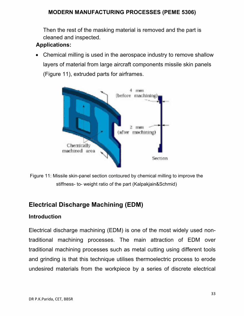
Chemical milling is used in the aerospace industry to remove shallow
layers of material from large aircraft components missile skin panels
(Figure 11), extruded parts for airframes.
Figure 11: Missile skin-panel section contoured by chemical milling to improve the
stiffness- to- weight ratio of the part (Kalpakjain&Schmid)
Electrical Discharge Machining (EDM)
Introduction
Electrical discharge machining (EDM) is one of the most widely used non-
traditional machining processes. The main attraction of EDM over
traditional machining processes such as metal cutting using different tools
and grinding is that this technique utilises thermoelectric process to erode
undesired materials from the workpiece by a series of discrete electrical

MODERN MANUFACTURING PROCESSES (PEME 5306)
34DR P.K.Parida, CET, BBSR
sparks between the workpiece and the electrode. A picture of EDM
machine in operation is shown in Figure 12.
Figure 12: Electrical discharge machine
The traditional machining processes rely on harder tool or abrasive
material to remove the softer material whereas non-traditional
machining processes such as EDM uses electrical spark or thermal
energy to erode unwanted material in order to create desired shape.
So, the hardness of the material is no longer a dominating factor for
EDM process. A schematic of an EDM process is shown in Figure 13,
where the tool and the workpiece are immersed in a dielectric fluid.

MODERN MANUFACTURING PROCESSES (PEME 5306)
35DR P.K.Parida, CET, BBSR
Figure 13: Schematic of EDM process EDM removes material by discharging an electrical current, normally stored in a capacitor bank, across a small gap between the tool (cathode) and the workpiece (anode) typically in the order of 50 volts/10amps.
EDM – Components
The main components in EDM:
Electric power supply Dielectric medium Work piece & tool Servo control unit.
The work piece and tool are electrically connected to a DC power supply.
The current density in the discharge of the channel is of the order of 10000 A/cm2 and power density is nearly 500 MW/cm2.
A gap, known as SPARK GAP in the range, from 0.005 mm to 0.05 mm is maintained between the work piece and the tool.

MODERN MANUFACTURING PROCESSES (PEME 5306)
36DR P.K.Parida, CET, BBSR
Dielectric slurry is forced through this gap at a pressure of 2 kgf/cm2 or lesser.
EDM – Working Principle
It is a process of metal removal based on the principle of material removal by an interrupted electric spark discharge between theelectrode tool and the work piece.
In EDM, a potential difference is applied between the tool and workpiece.
Essential - Both tool and work material are to be conductors. The tool and work material are immersed in a dielectric medium. Generally kerosene or deionised water is used as the dielectric
medium. A gap is maintained between the tool and the workpiece. Depending upon the applied potential difference (50 to 450 V) and
the gap between the tool and workpiece, an electric field would be established.
Generally the tool is connected to the negative terminal (cathode) of the generator and the workpiece is connected to positive terminal (anode).
As the electrons get accelerated, more positive ions and electrons would get generated due to collisions.
This cyclic process would increase the concentration of electrons and ions in the dielectric medium between the tool and the job at the spark gap.
The concentration would be so high that the matter existing in that channel could be characterised as “plasma”.
The electrical resistance of such plasma channel would be very less. Thus all of a sudden, a large number of electrons will flow from tool to
job and ions from job to tool. This is called avalanche motion of electrons. Such movement of electrons and ions can be visually seen as a
spark. Thus the electrical energy is dissipated as the thermal energy of the
spark. The high speed electrons then impinge on the job and ions on the
tool.

MODERN MANUFACTURING PROCESSES (PEME 5306)
37DR P.K.Parida, CET, BBSR
The kinetic energy of the electrons and ions on impact with the surface of the job and tool respectively would be converted into thermal energy or heat flux.
Such intense localized heat flux leads to extreme instantaneous confined rise in temperature which would be in excess of 10,000oC.
Such localized extreme rise in temperature leads to material removal. Material removal occurs due to instant vaporization of the material as
well as due to melting. The molten metal is not removed completely but only partially.
Electrode Material Electrode material should be such that it would not undergo much tool wear when it is impinged by positive ions. Thus the localized temperature rise has to be less by tailoring or properly choosing its properties or even when temperature increases, there would be less melting. Further, the tool should be easily workable as intricate shaped geometric features are machined in EDM.Thus the basic characteristics of electrode materials are:
High electrical conductivity – electrons are cold emitted more easily and there is less bulk electrical heating
High thermal conductivity Higher density High melting point – high melting point leads to less tool wear due to
less tool material melting for the same heat load Easy manufacturability Cost – cheape.g, Graphite ,Electrolytic oxygen free copper
,Tellurium copper – 99% Cu +0.5% tellurium ,Brass
Working principle of EDM
As shown in Figure 12, at the beginning of EDM operation, a high voltage is
applied across the narrow gap between the electrode and the workpiece.
This high voltage induces an electric field in the insulating dielectric that is
present in narrow gap between electrode and workpiece. This cause
conducting particles suspended in the dielectric to concentrate at the points
of strongest electrical field. When the potential difference between the

MODERN MANUFACTURING PROCESSES (PEME 5306)
38DR P.K.Parida, CET, BBSR
electrode and the workpiece is sufficiently high, the dielectric breaks down
and a transient spark discharges through the dielectric fluid, removing small
amount of material from the workpiece surface. The volume of the material
removed per spark discharge is typically in the range of 10-6 to 10-6 mm3.
The material removal rate, MRR, in EDM is calculated by the following formula:
MRR = 40 I / Tm 1.23 (cm3/min)
Where, I is the current amp,
Tmis the melting temperature of workpiece in 0C
Mechanism of metal removal
Fundamentally, the electro sparking method of metal working involves an electric erosion effect which connotes the breakdown of electrode material accompanying any form of electric discharge. A necessary condition for producing a discharge is the ionization of the dielectric that is splitting up of its molecules into ions and electrons. Consider the case of a discharge between two electrodes (tool cathode

MODERN MANUFACTURING PROCESSES (PEME 5306)
39DR P.K.Parida, CET, BBSR

MODERN MANUFACTURING PROCESSES (PEME 5306)
40DR P.K.Parida, CET, BBSR
along the electric lines of force, thus forming current carrying bridges. Discharge then occurs along one of these bridges as a result of ionization

MODERN MANUFACTURING PROCESSES (PEME 5306)
41DR P.K.Parida, CET, BBSR

MODERN MANUFACTURING PROCESSES (PEME 5306)
42DR P.K.Parida, CET, BBSR

MODERN MANUFACTURING PROCESSES (PEME 5306)
43DR P.K.Parida, CET, BBSR

MODERN MANUFACTURING PROCESSES (PEME 5306)
44DR P.K.Parida, CET, BBSR

MODERN MANUFACTURING PROCESSES (PEME 5306)
45DR P.K.Parida, CET, BBSR

MODERN MANUFACTURING PROCESSES (PEME 5306)
46DR P.K.Parida, CET, BBSR

MODERN MANUFACTURING PROCESSES (PEME 5306)
47DR P.K.Parida, CET, BBSR
MODERN MANUFACTURING PROCESSES (PEME 5306)
48DR P.K.Parida, CET, BBSR
MODERN MANUFACTURING PROCESSES (PEME 5306)
49DR P.K.Parida, CET, BBSR

MODERN MANUFACTURING PROCESSES (PEME 5306)
50DR P.K.Parida, CET, BBSR
Dielectric Fluids
For dielectric fluids to be used in EDM process, it is essential that they should
(i) Remain electrically non conductive until the required breakdown voltage is reached, that is they should have high dielectric strength.
MODERN MANUFACTURING PROCESSES (PEME 5306)
51DR P.K.Parida, CET, BBSR

MODERN MANUFACTURING PROCESSES (PEME 5306)
52DR P.K.Parida, CET, BBSR
Application of EDM
The EDM process has the ability to machine hard, difficult-to-machine materials. Parts with complex, precise and irregular shapes for forging, press tools, extrusion dies, difficult internal shapes for aerospace and medical applications can be made by EDM process. Some of the shapes made by EDM process are shown in Figure 14.
Figure 14: Difficult internal parts made by EDM process
Advantages of EDM
The main advantages of DM are:
By this process, materials of any hardness can be machined;
No burrs are left in machined surface; One of the main advantages of this process is that thin and
fragile/brittle components can be machined without distortion;
Complex internal shapes can be machined
Limitations of EDM
The main limitations of this process are:
This process can only be employed in electrically conductive
materials;

MODERN MANUFACTURING PROCESSES (PEME 5306)
53DR P.K.Parida, CET, BBSR
Material removal rate is low and the process overall is slow compared
to conventional machining processes;
Unwanted erosion and over cutting of material can occur;
Rough surface finish when at high rates of material removal.
Dielectric fluids
Dielectric fluids used in EDM process are hydrocarbon oils, kerosene and deionised water. The functions of the dielectric fluid are to:
Act as an insulator between the tool and the workpiece.
Act as coolant.
Act as a flushing medium for the removal of the chips.
The electrodes for EDM process usually are made of graphite, brass, copper and copper-tungsten alloys.
Design considerations for EDM process are as follows:
Deep slots and narrow openings should be avoided.
The surface smoothness value should not be specified too fine.
Rough cut should be done by other machining process. Only finishing
operation should be done in this process as MRR for this process is
low.
Wire EDM
EDM, primarily, exists commercially in the form of die-sinking machines
and wire-cutting machines (Wire EDM). The concept of wire EDM is shown
in Figure 15. In this process, a slowly moving wire travels along a
prescribed path and removes material from the workpiece. Wire EDM uses
electro-thermal mechanisms to cut electrically conductive materials. The
material is removed by a series of discrete discharges between the wire
electrode and the workpiece in the presence of dielectric fluid, which

MODERN MANUFACTURING PROCESSES (PEME 5306)
54DR P.K.Parida, CET, BBSR
creates a path for each discharge as the fluid becomes ionized in the gap.
The area where discharge takes place is heated to extremely high
temperature, so that the surface is melted and removed. The removed
particles are flushed away by the flowing dielectric fluids.
The wire EDM process can cut intricate components for the electric and
aerospace industries. This non-traditional machining process is widely used
to pattern tool steel for die manufacturing.
The wires for wire EDM is made of brass, copper, tungsten, molybdenum.
Zinc or brass coated wires are also used extensively in this process. The
wire used in this process should possess high tensile strength and good
electrical conductivity.
Figure 15: Wire erosion of an extrusion die
Wire EDM can also employ to cut cylindrical objects with high precision.
The sparked eroded extrusion dies are presented in Figure 16.

MODERN MANUFACTURING PROCESSES (PEME 5306)
55DR P.K.Parida, CET, BBSR
Figure 16: Sparked eroded extrusion diesThis process is usually used in conjunction with CNC and will only work
when a part is to be cut completely through. The melting temperature of the
parts to be machined is an important parameter for this process rather than
strength or hardness. The surface quality and MRR of the machined
surface by wire EDM will depend on different machining parameters such
as applied peak current, and wire materials.

MODERN MANUFACTURING PROCESSES (PEME 5306)
56DR P.K.Parida, CET, BBSR
Module-III
PLASMA ARC MACHINING (PAM):Introduction A plasma is defined as a superheated, electrically ionized gas. Plasma Arc Cutting(PAC) uses a plasma stream operating at temperatures in the range from 10,000 to 14,000 ºC to cut metal by melting. The cutting action takes place by directing the high velocity plasma stream at the work, thus melting it and blowing the molten metal through the kerf. Plasma is encountered in electrical discharges, such as fluorescent tubes and electric arcs, lightning, high temperature combustion flames and the sun. Most application of PAC involve cutting of flat metal sheets and plates. Operations include hole piercing and cutting along a defined path. It was initially employed to cut metals that are difficult to machine by conventional methods. However, in recent years, PAC has also been used to cut plain carbon steel, stainless steel and aluminium.Principle:When heated to elevated temperatures, gases turn into a distinctly different type of matter, which is plasma. When gases are heated by an applied electric field, an igniter supplies the initial electrons, which accelerate in the field before colliding and ionizing the atoms. The free electrons, in turn, get accelerated and cause further ionization and heating of the gases. The avalanche continues till a steady state is obtained in which the rate of production of the free charges is balanced by recombination and loss of the free charges to the walls and electrodes. The actual heating of the gas takes place due to the energy liberated when free ions and electrons recombine into atoms or when atoms recombine into molecules
Types of Plasma Arc Cutting system:
There are different types of plasma arc cutting operations are here. So there are 2 main configurations are there.
non-transferred mode, transfer mode

MODERN MANUFACTURING PROCESSES (PEME 5306)
57DR P.K.Parida, CET, BBSR
So this plasma gas is flowing surrounding this cathode. So this surrounding this cathode this plasma gas is coming and it is passing, this high velocity plasma gas is passing through this nozzle here. So it is passing through the nozzle. When it is passing through this nozzle, it is ionized, this plasma gas high pressurized, high velocity plasma gas is ionized and using this non-transferred mode any kind of material whether it is electrically conducting or electrically non-conducting, any kind of material can be cut or machined. So this non-transferred arc, arc between electrode and nozzle so this is arc is generated between this electrode and this nozzle. So here electrode this cathode and nozzle is connected to the anode and electrothermal efficiency of this kind of non-transferred arc is 65 to 70%. So it has a very low efficiency, low efficiency than this transferred mode. So ionizes high velocity gas streaming towards the workpiece when it is passing through this cathode or electrode and the nozzle so high velocity plasma jet is actually here, it is ionizes. So workpiece conductivity is not a

MODERN MANUFACTURING PROCESSES (PEME 5306)
58DR P.K.Parida, CET, BBSR
constant. So any kind of material, any kind of workpiece material, whether it is electrically conducting or non-conducting, any kind of material can be cut by this plasma, non-transferred mode of plasma arc cutting operation. But in this transferred mode you can see here this is the electrode here and this positive terminal is connected to the workpiece. So here the main constant is that this workpiece should be electrically conducting material. So this kind of transferred mode can be used only for electrically conducting mode of electrically conducting workpiece material. So here plasma gas is coming surrounding this electrode and while it is passing through this so it is ionized here in this zone it is ionized while it is passing through this nozzle it is ionized. So electrical efficiency, electrothermal efficiency of this kind of transfer mode, it is higher than this non-transfer mode, here it is 85 to 90% electrothermal efficiency for transferred mode or plasma arc nozzle. So arcing is generated between the electrode and the workpiece and arc heats of this coaxial-flowing gas so this is coaxial flowing plasma gas okay so maintains it in a plasma state. So here this workpiece is electrically conducting. So these are the 2 modes arc mode, one is the non-transferred and second one is the transferred arc mode.
Equipment
Elements of Plasma Arc system are power supply Gas supply Cooling water system Control console Plasma tourch
So first one is the power supply. Second one is the gas supply, plasma gas supply system, then cooling water system. So you have to cool down this nozzle as well as the plasma jet you have to cool down and then control console. So this plasma jet can be controlled by using a CNC machining system or this working table may be controlled by using a CNC machining system, CNC system so that any complicated contour can be cut from the workpiece material and also the fifth one is the fifth one of the plasma arc system, plasma arc cutting system is the plasma torch.

MODERN MANUFACTURING PROCESSES (PEME 5306)
59DR P.K.Parida, CET, BBSR
Mechanism of material removal:
The metal removal in PAM is basically due to the high temperature produced. The heating of the work piece is, as a result of anode heating, due to direct electron bombardment plus convection heating from the high temperature plasma that accompanies the arc. The heat produced is sufficient to raise the work piece temperature above its melting point andthe high velocity gas stream effectively blows the molten metal away.
Process Parameters: Parameters that govern the performance of PAM can be divided into three categories:
1. Those associated with the design and operation of the torch –electrical power delivered , the gases used to form the plasma, the

MODERN MANUFACTURING PROCESSES (PEME 5306)
60DR P.K.Parida, CET, BBSR
flow rate of the gases through the torch, the orifice diameter through the nozzle duct.
2. Those associated with the physical configuration of the set up – torch standoff, angle to the work, depth of cut, feed into the work and speed of the work toward the torch.
3. Environment in which the work is performed – cooling that is done on the bar, any protective type of atmosphere used to reduce oxidation for the exposed high temperature machined surface and any means that might be utilized to spread out or deflect the arc and plasma impingement area.
Gas Cutting PAM1.Oxidation of the work piece meltedgenerates the heat to melt the material for (e.g) in cutting steel, fuel gas is used to heat it to 7600-8700C at while steel reacts rapidly with oxygen to form iron oxide. The heat generated by the burning iron is sufficient ot melt the iron oxide.2.Oxy-fuel gas cutting is mostlylimited to only ferrous metal especially plain carbon steels.3.Cutting speed are lower for (e.g) incutting mild steel 19mm thick can be cut at 500 mm /min.4.Operating costs are higher5.Limited to the max. temperature of the chemical reaction (burning)6.Cost of equipment is lower.Surfaces are less smoother than those cut by PAM
1. Plasma is generated by subjecting a volume of gas to electronbombardment of an electric arc. The anode heating due to direct electron bombardment plus convective heating from the high temp plasma raises the material to the molten point and the high velocity gas stream effectively blows the material away.2.Because of the high temp involved, the process can be used on almost all material including those white are resistant to oxy- fuel gas cutting3. Cutting speeds are higher and leave a narrower kerf. They can cut mild steel 19mm thick at the rate of 1775mm /min.4. Operating costs are lower. Ratio ofsavings in favor of PAM is about 3:15. Seems to be unlimited. The greater the power used, the greater the volume of kerf material that can be removed.6. High initial cost of the equipment.7.Surfaces cut by plasma torch aresmoother but the edges are rounded.

MODERN MANUFACTURING PROCESSES (PEME 5306)
61DR P.K.Parida, CET, BBSR
Advantages The main advantage of PAM is speed. For example, mild steel of
6mm thick can be cut at 3m/min The plasma arc can be used to cut any metal or even to non
conducting materials like concrete etc., since it is primarily a melting process
Due to high speed of cutting the deformation of sheet metals is reduced while the width of the cut is minimum
Owing to the high productivity of the plasma arc cutting coupled with the tendency to use cheap and easily available plasma-forming media (air, water, ammonia etc.,), PAC is finding ever increasing application.
Smooth cuts free from contaminants are obtained in the process Profile cutting of metals especially of stainless steel and aluminium
can be very easily done by PAM Operating costs are less when compared to oxy-fuel torch Can be automated
Limitations The main disadvantage of PAC is the high initial cost of the
equipment. However, it can be made economical, if the quantity involved is large and the thickness is up to 50mm.
Well-attached drops on the underside of the cut can be a problem and there will be heat affected zone (HAZ). The depth of HAZdepends on the material and its thickness
Smoke and noise Sharp corners are difficult to produce because of the wide diameter of
the plasma stream Burr is often produced Taper on the work-piece may occur
Applications Chiefly used to cut stainless steel and aluminium alloys. It is preferred
to oxy-fuel cutting because it produces comparatively smoother cuts and is free from contamination

MODERN MANUFACTURING PROCESSES (PEME 5306)
62DR P.K.Parida, CET, BBSR
Other metals which are resistant to oxy-fuel cutting and hence cut by PAC are magnesium, titanium, copper, nickel and alloys of copper and nickel
PAC can be used for stack cutting, plate beveling, shape cutting and piercing.
It can also be used for underwater cutting. The plasma jets are used for welding materials like titanium, stainless
steel etc., Plasma arc is used for depositing filler metal on surface to obtain
desired properties like corrosion resistance, wear resistance, toughness or anti-friction properties – Plasma arc surfacing
The plasma arc can also be used for spraying a prepared surface of the base material with droplets of molten metal to obtain a surface of required thickness

MODERN MANUFACTURING PROCESSES (PEME 5306)
63DR P.K.Parida, CET, BBSR
Laser–Beam Machining (LBM)
Laser-beam machining is a thermal material-removal process that utilizes a
high-energy, coherent light beam to melt and vaporize particles on the
surface of metallic and non-metallic workpieces. Lasers can be used to cut,
drill, weld and mark. LBM is particularly suitable for making accurately
placed holes. A schematic of laser beam machining is shown in Figure 17.
Different types of lasers are available for manufacturing operations which are as follows:
CO2 (pulsed or continuous wave): It is a gas laser that emits light in
the infrared region. It can provide up to 25 kW in continuous-wave
mode.
Nd:YAG: Neodymium-doped Yttrium-Aluminum-Garnet (Y3Al5O12)
laser is a solid-state laser which can deliver light through a fibre-optic
cable. It can provide up to 50 kW power in pulsed mode and 1 kW in
continuous-wave mode.
Figure 17: Laser beam machining schematic

MODERN MANUFACTURING PROCESSES (PEME 5306)
64DR P.K.Parida, CET, BBSR
Laser beam cutting (drilling)
In drilling, energy transferred (e.g., via a Nd:YAG laser) into the
workpiece melts the material at the point of contact, which
subsequently changes into a plasma and leaves the region.
A gas jet (typically, oxygen) can further facilitate this phase
transformation and departure of material removed.
Laser drilling should be targeted for hard materials and hole
geometries that are difficult to achieve with other methods.
A typical SEM micrograph hole drilled by laser beam machining process
employed in making a hole is shown in Figure 18.
Figure 18: SEM micrograph hole drilled in 250 micro meter thick Silicon Nitride with 3rd harmonic Nd: YAG laser
Laser beam cutting (milling)
A laser spot reflected onto the surface of a workpiece travels along a
prescribed trajectory and cuts into the material.

MODERN MANUFACTURING PROCESSES (PEME 5306)
65DR P.K.Parida, CET, BBSR
Continuous-wave mode (CO2) gas lasers are very suitable for laser
cutting providing high-average power, yielding high material-removal
rates, and smooth cutting surfaces.
Advantage of laser cutting No limit to cutting path as the laser point can move any path. The process is stress less allowing very fragile materials to be laser
cut without any support. Very hard and abrasive material can be cut. Sticky materials are also can be cut by this process. It is a cost effective and flexible process. High accuracy parts can be machined. No cutting lubricants required No tool wear Narrow heat effected zone
Limitations of laser cutting Uneconomic on high volumes compared to stamping Limitations on thickness due to taper High capital cost High maintenance cost Assist or cover gas required
Applications LBM can make very accurate holes as small as 0.005 mm in
refractory metals ceramics, and composite material without warping the workpieces.
This process is used widely for drilling and cutting of metallic and non-metallic materials.
Laser beam machining is being used extensively in the electronic and automotive industries.

MODERN MANUFACTURING PROCESSES (PEME 5306)
66DR P.K.Parida, CET, BBSR
Electron Beam Machining (EBM)
In electron beam machining process there is a bombardment of high velocity stream of electrons on the work-piece surface so this electrons are bombarded on the work piece surface with a very high velocity, around 66% velocity of the sunlight so because of this bombardment of electrons on the work piece surface the materials into a small area on the work piece surface it melts and vaporizes and temperature rises to a very high temperature. So material on the work piece surface melts and vaporizes and machining is going on. So this process actually it is used for machining thousands of holes on a thin sheet which is used in aerospace industry, food processing industry, cloth industries and very high aspect ratio for making of very high aspect ratio holes, thousands of holes on a work piece surface irrespective of the material property like metallurgical property, mechanical property of the material. So this material maybe electrically conducting or electrically non-conducting or maybe ceramics, metals, or any kind of metal, any kind of ceramics it works. So here there is a filament which is heated with a very high temperature. So because of this heating of this filament so electrons emanates from that cathode, cathode filament or these filament may be heated from a radiation from a another body, from the radiation from a another body on a solid block of cathode, on a solid block of filament also it can be generated. So these electrons emits from the cathode, cathode filament and it passes through a magnetic lens to coincide to concentrate or to reduce the diameter of the electron beam and it bombards on the work piece surface.
Types of EBM
Electron beam machining process there are 2 types of methods are there. One is the thermal type. Another one is the non-thermal type. So in normal in non-thermal type this electron beams are used for generating chemical reactions. So for generating chemical reactions the electron beams are used. So this non-thermal type we are not going to discuss. We are going to discuss only thermal type of electron beam machining process.

MODERN MANUFACTURING PROCESSES (PEME 5306)
67DR P.K.Parida, CET, BBSR
In thermal type this cathode is heated to a very high temperature. So this stream of large number of electrons comes as a small diameter beam, electron beam.
So this stream of large number of electrons emits from the cathode, from a heated cathode. It comes out as a small diameter beam. So it moves towards the workpiece with a very high velocity and it bombards, machining is going on due to the bombardment of these electrons on a very small localized area. So as it is bombarded on a very small localized area, huge amount of temperature is generated on the workpiece surface. So machining is going on due to the melting and vaporization of this material from the workpiece surface from a much localized area.
Equipment and working of EBMFig. below shows the schematic representation of an electron beam gun, which is the heart of any electron beam machining facility. The basic functions of any electron beam gun are to generate free electrons at the cathode, accelerate them to a sufficiently high velocity and to focus them

MODERN MANUFACTURING PROCESSES (PEME 5306)
68DR P.K.Parida, CET, BBSR
over a small spot size. Further, the beam needs to be manoeuvred if required by the gun. The cathode as can be seen in Fig. is generally made of tungsten or tantalum. Such cathode filaments are heated, often inductively, to a
temperature of around 25000C. Such heating leads to thermo-ionic
emission of electrons, which is further enhanced by maintaining very low vacuum within the chamber of the electron beam gun. Moreover, this cathode cartridge is highly negatively biased so that the thermo-ionic electrons are strongly repelled away form the cathode. This cathode is often in the form of a cartridge so that it can be changed very quickly to reduce down time in case of failure.
Electron beam gun

MODERN MANUFACTURING PROCESSES (PEME 5306)
69DR P.K.Parida, CET, BBSR
Just after the cathode, there is an annular bias grid. A high negative bias is applied to this grid so that the electrons generated by this cathode do not diverge and approach the next element, the annular anode, in the form of a beam. The annular anode now attracts the electron beam and gradually gets accelerated. As they leave the anode section, the electrons may achieve a velocity as high as half the velocity of light. The nature of biasing just after the cathode controls the flow of electrons and the biased grid is used as a switch to operate the electron beam gun in pulsed mode. After the anode, the electron beam passes through a series of magnetic lenses and apertures. The magnetic lenses shape the beam and try to reduce the divergence. Apertures on the other hand allow only the convergent electrons to pass and capture the divergent low energy electrons from the fringes. This way, the aperture and the magnetic lenses improve the quality of the electron beam. Then the electron beam passes through the final section of the electromagnetic lens and deflection coil. The electromagnetic lens focuses the electron beam to a desired spot. The deflection coil can manoeuvre the electron beam, though by small amount, to improve shape of the machined holes. Generally in between the electron beam gun and the workpiece, which is also under vacuum, there would be a series of slotted rotating discs. Such discs allow the electron beam to pass and machine materials but helpfully prevent metal fumes and vapour generated during machining to reach the gun. Thus it is essential to synchronize the motion of the rotating disc and pulsing of the electron beam gun. Electron beam guns are also provided with illumination facility and a telescope for alignment of the beam with the workpiece. Workpiece is mounted on a CNC table so that holes of any shape can be machined using the CNC control and beam deflection in-built in the gun. One of the major requirements of EBM operation of electron beam gun is maintenance of desired vacuum. Level of vacuum within the gun is in the
order of 10-4
to 10-6
Torr. {1 Torr = 1mm of Hg} Maintenance of suitable vacuum is essential so that electrons do not loose their energy and a significant life of the cathode cartridge is obtained. Such vacuum is achieved and maintained using a combination of rotary pump and diffusion

MODERN MANUFACTURING PROCESSES (PEME 5306)
70DR P.K.Parida, CET, BBSR
pump. Diffusion pump, as shown in Fig. 9.6.4 is attached to the diffusion pump port of the electron beam gun (vide Fig. 9.6.3). Diffusion pump is essentially an oil heater. As the oil is heated the oil vapour rushes upward where gradually converging structure as shown in Fig. 9.6.4 is present. The nozzles change the direction of motion of the oil vapour and the oil vapour starts moving downward at a high velocity as jet. Such high velocity jets of oil vapour entrain any air molecules present within the gun. This oil is evacuated by a rotary pump via the backing line. The oil vapour condenses due to presence of cooling water jacket around the diffusion pump.
Electron Beam Process – Parameters
The process parameters, which directly affect the machining characteristics in Electron Beam Machining, are:
• The accelerating voltage • The beam current • Pulse duration • Energy per pulse • Power per pulse • Lens current • Spot size • Power density
As has already been mentioned in EBM the gun is operated in pulse mode. This is achieved by appropriately biasing the biased grid located just after the cathode. Switching pulses are given to the bias grid so as to achieve pulse duration of as low as 50 μs to as long as 15 ms. Beam current is directly related to the number of electrons emitted by the cathode or available in the beam. Beam current once again can be as low as 200 μamp to 1 amp.Increasing the beam current directly increases the energy per pulse. Similarly increase in pulse duration also enhances energy per pulse. High-energy pulses (in excess of 100 J/pulse) can machine larger holes on thicker plates. The energy density and power density is governed by energy per pulse duration and spot size. Spot size, on the other hand is controlled by the degree of focusing achieved by the electromagnetic lenses. A higher

MODERN MANUFACTURING PROCESSES (PEME 5306)
71DR P.K.Parida, CET, BBSR
energy density, i.e., for a lower spot size, the material removal would be faster though the size of the hole would be smaller. The plane of focusing would be on the surface of the workpiece or just below the surface of the workpiece. This controls the kerf shape or the shape of the hole as schematically shown in Fig. 9.6.5.
Typical kerf shape of electron beam drilled hole
As has been indicated earlier, the final deflection coil can manoeuvre the electron beam providing holes of non-circular cross-section as required.
Advantages EBM provides very high drilling rates when small holes with large
aspect ratio are to be drilled. Moreover it can machine almost any material irrespective of their
mechanical properties. As it applies no mechanical cutting force, work holding and fixturing cost is very less.

MODERN MANUFACTURING PROCESSES (PEME 5306)
72DR P.K.Parida, CET, BBSR
Further for the same reason fragile and brittle materials can also be processed.
The heat affected zone in EBM is rather less due to shorter pulses. EBM can provide holes of any shape by combining beam deflection
using electromagnetic coils and the CNC table with high accuracy.
Limitations
The primary limitations are the high capital cost of the equipment and necessary regular maintenance applicable for any equipment using vacuum system.
Moreover in EBM there is significant amount of non-productive pump down period for attaining desired vacuum.
However this can be reduced to some extent using vacuum load locks.
Though heat affected zone is rather less in EBM but recast layer formation cannot be avoided.

MODERN MANUFACTURING PROCESSES (PEME 5306)
73DR P.K.Parida, CET, BBSR
Module-IVIntroduction to Surface engineeringThe majority of material failure originates at surface by mechanism involving wear, corrosion and fatigue. In case of metals, one technique for controlling surface initiated failure is through use of alloying elements throughout the bulk of these specimens to suitably modify the hardness, chemical passivity or strength characteristics. However this method is considered inefficient due to the use of costly strategic alloying elements like Chromium(Cr) and Cobolt (Co). The reorganization that vast majority of engineering components fails catastrophically in service through surface related phenomena, led to the development of broad interdisciplinary subject of “Surface Engineering”. Surface Engineering could be best defined as design of surface and substrate together as a system to give cost effective performance enhancement of which neither is capable of its own. The definition of surface engineering is given as “The application of traditional and innovative surface technologies to engineering components and materials with properties unattainable in either the base metal or surface materials”. Frequently the various surface technologies are applied to existing design of engineering components but ideally surface engineering involves design of component with knowledge of surface treatment to be employed. OR As per Definition by ASM Handbook treatment of the surface and near-surface regions of a material to allow the surface to perform functions that are distinct from those functions demanded from the bulk of the material. Surface engineering, is a discipline of science and technology, which meets the expectations of modem technical science: energy, material efficiency, as well as environment friendliness.
CLASSIFICATION OF SURFACE ENGINEERING
(I) Changing the Surface Metallurgy: None of these process changes the surface chemistry, but they improve properties like wear and fatigue by changing surface metallurgy a) Localized surface hardening (flame, induction, laser, and electron-beam hardening): Improves wear resistance through the development of a hard martensitic surface. (b) Laser melting: Improves wear resistance through grain refinement and the formation offine dispersions of precipitates on the surface.

MODERN MANUFACTURING PROCESSES (PEME 5306)
74DR P.K.Parida, CET, BBSR
c) Shot peening: Shot peening is a surface enhancement process which produces beneficial compressive residual stresses on metallic surfaces. This improves fatigue strength and relieves tensile stresses that contribute to stress-corrosion cracking. (II) Changing the Surface Chemistry Surface modification processes have advantage over coating primarily because they
(1) usually impart internal compressive stresses in near surface region and
(2) Will not delaminate off the substrate.
The process includes: (a) Chemical or electrochemical conversion treatment that produce complex phosphates, chromates/oxides on metal surface. (b) Thermo chemical diffusion heat treatment that involves the introduction of interstitial elements like C, N or B into ferrous alloy surface at elevated temperature. (c)Pack cementation diffusion treatments that involve the introduction of aluminium(Al), Cr or silicon(Si) into alloy surface. (d) Surface modification by ion implantation, which involves introduction of ionized species (virtually any element) into the substrate using ion beam of high velocity electrons. (e) Surface modification by combination oflaser beam melting and alloying.
(III) Adding a Surface Layer or Coating This involves an intentional buildup or addition of new layer on metal substrate i.e. application of coating or lining. A wide range of processes are used to deposit metal/ceramic and Qrganic (paints or plastic and rubber coating).Coating methods commonly used are:
I. Organic coatings and lining II. Ceramic coatings III. Hot dip metallic coatings IV. Electroplating (metal or composite coating) V. Weld overlays (metal or ceramic coating) VI. Cladding (thick metal coating) VII. Thermo reactive deposition/diffusion process (carbides, nitrides or
earbonitrides)

MODERN MANUFACTURING PROCESSES (PEME 5306)
75DR P.K.Parida, CET, BBSR
Amongst all the above methods of coating deposition, ceramic coatings have advantages since Ceramic materials are noted for their high hot hardness and good chemical and thermal stability, making their surface properties ideal for number of engineering products, which encounter demanding operating conditions. The deposition of ceramic phases onto conventional metallic materials results in good combination of bulk toughness and load support with desirable surface characteristics and also making forming of complex shapes easier.
METHODS OF DEPOSITING CERAMIC COATINGS:
1. Thermal Spraying: 2. Sol Gel technique 3. Chemical Vapor Deposition Technique (CVD) 4. Physical Vapor Deposition Technique (PVD)
Thermal Spraying Thermal spray is one ofthe most versatile deposition processes for coating materials and its use for industrial applications has been greatly increase. Thermal spraying is, in fact, a generic group ofprocesses in which the coating material is fed to a heating zone, where it becomes molten, and is then propelled to the surface to be coated . Metallic, ceramic, cermets and some polymeric materials can be used in the form ofpowder, wire, or rod for this purpose. (Fig 1.4.1)
Sol Gel technique The sol-gel technique is based on hydrolysis ofliquid precursors at low temperature and formation ofcolloidal sols. (Fig 1.4.2)
Chemical Vapor Deposition Technique (CVD ) CVD involves flowing a precursor gas or gases into a chamber containing one or more heated objects to be coated. Chemical reactions occurs on or near the hot surfaces resulting in deposition of thin films on the substrate, this is accompanied by the production of chemical byproducts that are exhausted out of chamber along with unreacted precursor gases.

MODERN MANUFACTURING PROCESSES (PEME 5306)
76DR P.K.Parida, CET, BBSR
Schematic diagram of various processes for Ceramic thin film deposition
Physical Vapor Deposition Technique (PVD) PVD processes are atomistic deposition processes in which material is vaporized from solid/liquid source in form of atoms/molecules, transported in form of vapor through a vacuum or low pressure gaseous or plasma environment to the substrate where it condenses. PVD can be used to deposit films of metals or alloys as well as compounds using reactive: deposition processes. The main advantage of PVD processes compared to CVD processes is the low deposition temperature (typically around 500°C).Because of low temperature and high growth rates involved PVD coatings have high compressive stresses while those formed under CVD have low tensile

MODERN MANUFACTURING PROCESSES (PEME 5306)
77DR P.K.Parida, CET, BBSR
stresses. If the layer contains more atoms in interstitial positions than there are vacancies in lattice and tensile stresses are formed like in case of CVD. While if layer contains more Vacancies in interstitial position and atoms in lattice compressive stresses are formed. In Addition to this other advantages include excellent adhesion, good thickness uniformity, wide range of coating and substrate materials is possible and no hydrogen embrittlement problem. PVD Titanium Nitride (TiN) is superior to CVD TiN coating in increasing the metal cutting performance of Cemented carbide tools owing to the former's greater resistance to abrasive wear and its associated higher surface fracture strength. This is due to fact that PVD TiN coating microstructure and beneficial compressive residual stress both of which contribute to higher micro hardness. However main disadvantage of PVD process is they are generally line of sight between surface to be coated and source. PVD thin films are widely used for surface protection, optical and electronic applications. Following figure shows the useage ofthin films for various applications.The largest application of PVD coatings is in surface protection for example in metal cutting fleld-particularly for twist drills, gear cutting tools, forming tools such as in cold backward impact of copper components, polymer processing machinery(injector screws),moulds for plastic, in food industry coating on stainless steel sleeve used for manufacturing of chocolate, in metrology field thread gauges and slip gauges, in medical applications for surgical tools, used in automotive parts of racing cam. Attractive golden color of TiN has led to its increasing use as decorative coating in jewellary applications. Cathode arc evaporation (CAE), one of the PVD processes has high deposition rates to produce dense and excellent adhesive coatings that offer a potential economical advantage. The industrial utilization of CAE is largely confined to mechanical applications, in particular to the deposition ofhard coatings on the cutting tools.
Micro and nano machining of glasses and ceramics Material removal at micro/nano level with no constraint on the size of the component being machined is called micro or nano machining respectively.Some examples are
Creating micro features or surface characteristics (especially surface finish) in the micro/nano level.

MODERN MANUFACTURING PROCESSES (PEME 5306)
78DR P.K.Parida, CET, BBSR
Removal of material in the form of chips or debris having the size in the range of microns.
Machining of micro parts is not literally correct as macro machining
The need for high precision in manufacturing was felt by manufacturers worldwide to improve interchangeability of components, improve quality control and longer wear/fatigue life
In the era of nanotechnology, deterministic high precision finishing methods are of utmost importance and are the need of present manufacturing scenario.
Final finishing operations in manufacturing of precise parts are always of concern owing to their most critical, labour intensive and least controllable nature
Reverse Engineering, Engineering is the process of designing, manufacturing, assembling, andmaintaining products and systems. There are two types of engineering, forward engineering and reverse engineering. Forward engineering is the traditional process of moving from high-level abstractions and logical designs to the physical implementation of a system. In some situations, there may be a physical part/product without any technical details, such as drawings, bills-of-material, or without engineering data. The process of duplicating an existing part, subassembly, or product, without drawings, documentation, or a computer model is known as reverse engineering. Reverse engineering is also defined as the process of obtaining a geometric CAD model from 3-D points acquired by scanning/digitizing existing parts/products. The process of digitally capturing the physicalentities of a component, referred to as reverse engineering (RE), is often defined by researchers with respect to their specific task.Reverse engineering is now widely used in numerous applications, such asManufacturing, industrial design, and jewelry design and reproduction For example, when a new car is launched on the market, competing manufacturers may buy one and disassemble it to learn how it was built and how it works. In software engineering, good source code is often a

MODERN MANUFACTURING PROCESSES (PEME 5306)
79DR P.K.Parida, CET, BBSR
variation of other good source code. In some situations, such as automotive styling, designers give shape to their ideas by using clay, plaster, wood, or foam rubber, but a CAD model is needed to manufacture the part. As products become more organic in shape, designing in CAD becomes more challenging and there is no guarantee that the CAD representation will replicate the sculpted model exactly.Reverse engineering provides a solution to this problem because the physical model is the source of information for the CAD model. This is also referred to as the physical-to-digital process depicted in Figure 1.2. Another reason for reverse engineering is to compress product development cycle times. In the intensely competitive global market, manufacturers are constantly seeking new ways to shorten lead times to market a new product. Rapid product development (RPD) refers to recently developed technologies and techniques that assist manufacturers and designers in meeting the demands of shortened product development time. For example, injection-molding companies need to shorten tool and die development time drastically. By using reverse engineering, a three-dimensional physical product or clay mock-up can be quickly captured in the digital form, remodeled, and exported for rapid prototyping/tooling or rapid manufacturing using multi-axis CNC machining techniques.
Concurrent Engineering In concurrent engineering (CE) product is developed by a team involving engineers from both the design section and the production shop. The advantages of concurrent engineering are based on the economic leverage of addressing all aspects of design of a product as early as possible. Hence using concurrent engineering most of the design modification is incorporated as early as possible. It is also true that the importance of early modification is very significant and the ability of the early change to influence the product cost is much larger as indicated. Hence using concurrent engineering most of the design modifications are incorporated as early as possible.
Rapid prototyping: Though the principle of concurrent engineering (CE) is quite clear and the advantages of the concept for improved quality and reduced cost are
MODERN MANUFACTURING PROCESSES (PEME 5306)
80DR P.K.Parida, CET, BBSR
implicit, it is not possible to incorporate CE effectively in the absence of some technique for quick development of prototype. To reduce the development time and adopt concurrent engineering in its true spirit, quick and inexpensive fabrication of prototype parts is essential and rapid prototyping technology has made that possible.
A family of unique fabrication processes developed to make engineering prototypes in minimum lead time based on a CAD model of the item •The traditional method is machining−Machining can require significant lead-times –several weeks, depending on part complexity and difficulty in ordering materials •RP allows a part to be made in hours or days given that a computer model of the part has been generated on a CAD system
References
1. Manufacturing Engineering and Technology Fifth Edition -
SeropeKalpakjian and Steven R Sschmid. (Prentice Hall), 2006.
2. Manufacturing Technology, Volume 2. R L Timings & S P Wilkinson
(Longman) 2000.
3. Manufacturing Processes and Equipment – George Tlusty(Prentice
Hall).
4. E. Paul DeGarmo, J.T. Black, R.A. Kohsern, Materials and Processes
in Manufacturing, 8th ed., Prentice-Hall, Englewood Cliffs, NJ, 1997,
pp. 941–947.
5. Chemical Machining, Metals Handbook, vol. 3, Machining, 8th ed.,
American Society for Metals, Metals Park, OH, pp. 240–248.
6. http://www.dimeg.unipd.it/didattica/31/8_Non_conventional.pdf

MODERN MANUFACTURING PROCESSES (PEME 5306)
81DR P.K.Parida, CET, BBSR
7. www.eng.morgan.edu
8. http://www.answers.com/topic/electrical-discharge-machining
9. http://www.exitech.co.uk/pdfFiles/Microhole%20Drilling%20using%20Reshaped%20Pulsed%20Gaussian%20Laser%20Beam.pdf
10.http://www.google.co.uk/search?q=ultrasonic+machining+picture&hl=en&start=10&sa=N
11.http://www.ebtecwelding.com/waterjet-cutting/wjetlimitations.html
12.http://www.waterjets.org/about_abrasivejets.html
13.http://www.waterjets.org/index.html