lecture14: plasma physics 1 - columbia...
TRANSCRIPT

Lecture14:
Plasma Physics 1APPH E6101x
Columbia University

This Lecture
• Langmuir probes
• Langmuir probes in magnetized plasma

Understanding Langmuir probe current-voltage characteristicsRobert L. Merlinoa!
Department of Physics and Astronomy The University of Iowa, Iowa City, Iowa 52242
!Received 26 February 2007; accepted 14 July 2007"
I give several simple examples of model Langmuir probe current-voltage !I-V" characteristics thathelp students learn how to interpret real I-V characteristics obtained in a plasma. Students can alsocreate their own Langmuir probe I-V characteristics using a program with the plasma density,plasma potential, electron temperature, ion temperature, and probe area as input parameters. Someexamples of Langmuir probe I-V characteristics obtained in laboratory plasmas are presented andanalyzed. A few comments are made advocating the inclusion of plasma experiments in theadvanced undergraduate laboratory. © 2007 American Association of Physics Teachers.
#DOI: 10.1119/1.2772282$
I. INTRODUCTION
Plasma physicists use Langmuir probes in low temperatureplasmas1 !approximately a few electron volts" to measure theplasma density, electron temperature, and the plasma poten-tial. A Langmuir probe consists of a bare wire or metal disk,which is inserted into a plasma and electrically biased withrespect to a reference electrode to collect electron and/orpositive ion currents. Examples of the use of a cylindrical!wire" probe in a gas discharge tube and a planar disk probein a hot filament discharge plasma are shown in Fig. 1.Probes, initially called “sounding electrodes,” were first usedin the late 19th and early 20th centuries in an attempt tomeasure the voltage distribution in gas discharges. A gasdischarge #Fig 1!a"$ is produced in a glass tube of about2–5 cm diameter and 20–40 cm long, which contains metaldisk electrodes !anode and cathode" at both ends. The tube isfirst evacuated and then refilled with a gas at low pressure!about 1 Torr or less" and an electrical discharge !ionized gasor “plasma”" is formed by applying a DC voltage of300–400 V across the electrodes. A common example of adischarge tube is an ordinary fluorescent light. Probes areinserted at one or more locations along the length of the tube,with the exposed tips protruding into the plasma column. Theearly users of probes naively assumed that the potential ofthe plasma at the location of the probe !known as the plasmapotential or space potential and designated as VP" could bedetermined by measuring the potential on the probe relativeto one of the electrodes. However, this procedure determinedthe floating potential Vf of the probe which is generally notthe same as the plasma potential. By definition, a probe thatis electrically floating, collects no net current from theplasma, and thus its potential rises and falls to whatever po-tential is necessary to maintain zero net current.
In a typical plasma, the electrons, because of their smallermass, have significantly higher thermal speeds than the posi-tive ions, even if the electrons and ions are at the same tem-perature. Usually the electrons have a higher temperaturethan the positive ions. Although a plasma is electrically neu-tral, and the electron and ion densities are very nearly equal,a floating probe will tend initially to draw a higher electroncurrent because the electrons reach the probe faster than themore massive ions. Because the net current to the floatingprobe must be zero, the probe floats to a negative potentialrelative to the plasma so that further collection of electrons isretarded and ion collection is enhanced. Thus, the floatingpotential is less than the plasma potential. The plasma poten-
tial is the potential of the plasma with respect to the walls ofthe device at a given location in the plasma. VP is generallya few volts positive with respect to the walls, again becausethe swifter electrons tend to escape to the walls first, leavingthe plasma with a slight excess of positive space charge. Thebulk of the plasma, however, is “quasineutral”!electron density% ion density", and the potential differencebetween the bulk of the plasma and the wall is concentratedin a thin layer or sheath near the wall. The gradient of theplasma potential determines the electric field that is respon-sible for energizing the electrons, which maintain the dis-charge through ionization.
Although physicists knew that Vf and VP were not thesame, they thought that the difference was probably small,and in any case, they had no way of either estimating thedifference or of measuring the actual plasma potential. IrvingLangmuir and Harold Mott-Smith of the General ElectricResearch Laboratory in the 1920s were the first to provide aquantitative understanding of the difference between Vf andVP. They developed an experimental method for determiningthe plasma potential and also showed how it was possible touse the probe !now known as a “Langmuir” probe" to deter-mine the plasma density and the electron temperature aswell.2 Langmuir’s method consists of obtaining the current-voltage !I-V" characteristic of the probe as the applied biasvoltage VB, is swept from a negative to a positive potential.
Many students of experimental plasma physics are giventhe task of constructing and implementing a Langmuir probein a plasma. They quickly realize that building the probe andobtaining a I-V characteristic is much easier than extractingaccurate values of the plasma parameters from the data. Theliterature dealing with the theory of the Langmuir probes isextensive, and new papers appear regularly. My purpose hereis not to discuss the complexities of probe theory, which istreated in a number of excellent monographs,3–9 but to pro-vide a method to help students understand why a Langmuircharacteristic looks the way it does. The difficulty with un-derstanding probe I-V characteristics stems from the fact thatthe electrons and ions are not monoenergetic and often havevery different temperatures. As a result, the probe sometimescollects only ion current, sometimes only electron current,and sometimes both. It is easier to understand and analyzethe full I-V characteristic if the ion and electron current con-tributions are separated.
In Sec. II we discuss the most basic aspects of probetheory needed to calculate the individual electron and ioncurrents, and then construct an ideal probe I-V relation using
1078 1078Am. J. Phys. 75 !12", December 2007 http://aapt.org/ajp © 2007 American Association of Physics Teachers

OCTOBER) 1926 PH YSICAL REVIEW VOLUME 28'
THE THEORY OF COLLECTORS IN GASEOUS DISCHARGES
BV H. M. MOTT-SMITH AND IRVING LANGMUIR
ABSTRACT
When a cylindrical or spherical electrode {collector) immersed in an ionizedgas is brought to a suitable potential, it becomes surrounded by a symmetricalspace-charge region or "sheath" of positive or of negative ions (or electrons).Assuming that the gas pressure is so low that the proportion of ions whichcollide with gas molecules in the sheath is negligibly small, the current takenby the collector can be calculated in terms of the radii of the collector or sheath,the distribution of velocities among the ions arriving at the sheath boundaryand the total drop of potential in the sheath. The current is independent of theactual distribution of potential in the sheath provided this distribution satisfiescertain conditions.
"Orbital Motion" equations for spherical and cylindrical collectors.—Generalformulas for the current are derived and the calculations are then carried outfor collectors in a group of ions having velocities which are (A) equal andparallel; (B) equal in magnitude but of random direction; (C) Maxwellian;(D) Maxwellian with a drift velocity superimposed. In all cases the collectorcurrent becomes practically independent of the sheath radius when thisradius is large compared with that of the collector. Thus the volt-amperecharacteristics of a collector of sufficiently small radius can be used to dis-tinguish between the diferent types of velocity distribution. General equationsare also given by means of which the velocity distribution can be calculateddirectly from the volt-ampere characteristics of a sphere or cylinder.
Special properties of the Maxmellian distribution. —For a collector of anyshape having a convex surface, the logarithm of the current taken from aMaxwellian distribution is a linear function of the voltage diAerence betweenthe collector and the gas when the collector potential is such as to retardarriving ions, but not when this potential is accelerating. This is a consequenceof the following general theorem: Supposing for simplicity of statement thatthe surface of an electrode of any shape immersed in a Maxwellian distributionis perfectly reflecting, then the ions in the surrounding sheath will havea distribution (called D~) of velocities and densities given by Maxwell's andBoltzmann's equations, even in the absence of collisions between the ions,provided that there are in the sheath no possible orbits in which an ion cancirculate without reaching the boundary; but if such orbits exist, the distribu-tion will be D~ except for the absence of such ions as would describe the circu-lating orbits. As another corollary of this theorem there is deduced an equmtionrelating the solution of problems having inverse geometry. Finally it is indi-cated how the theorem can be applied to calculate the volt-ampere char-acteristic of A. F. Dittmer's "pierced collector" when placed in a Maxwelliandistribution.
The egect of reflection of ions at the collector surface in modifying currentscalculated by the preceding equations is discussed.
727

COLLECTORS IN GASEOUS DISCHARGES
The volt ampere characteristic of a plane electrode of area A with aMaxwellian distribution is
i=IAe&, for g&0. (38)
Thus the cylinder, the sphere and the plane all have the same charac-teristic for retarding voltage in a Maxwellian distribution of ions. Aswe shall see later, this same characteristic is in fact possessed by acollector of any shape whatever.The curves of Fig. 4 illustrate the characteristics of the three forms
of collectors with a Maxwellian distribution.
FzG. 4.
(D) Distributiort which is llfctxwellictn with superimposed drift In.certain types of discharge there are groups of ions which presumablyhave the velocity distribution of a gas with "mass-motion. " For in-stance, in the case of a mercury-vapor arc passing through a tube ofuniform diameter, collectors are found to have characteristics which ifinterpreted according to the results of the last section would indicatethat the free electrons has a nearly perfect Maxwellian distribution ofvelocities. This would imply that there was no net transport of electronsin any direction, but actually the electrons must be drifting steadilytoward the anode. It becomes important therefore to 6nd what inter-pretation should be put upon the collector characteristics in view of thisfact.In the case just cited the drift velocity is usually small or at any rate
of the same order of magnitude as the average absolute velocity of theMaxwellian distribution. In other cases there exist in discharges beamsof electrons which have a common high drift velocity on which is super-

a set of model plasma parameters. A link is provided to aprogram that allows the user to input the plasma and probeparameters !density, temperature, plasma potential, andprobe dimension" and plot the resulting Langmuir I-V char-acteristic. Section III provides two examples of real Lang-muir probe I-V characteristics obtained in laboratory plas-mas. I close in Sec. IV with comments advocating theinclusion of plasma experiments in the undergraduate ad-vanced laboratory course.
II. MODEL LANGMUIR PROBE CURRENT-VOLTAGE CHARACTERISTICS
In this section I discuss some of the basic aspects of Lang-muir probe theory that are needed to construct model probeI-V characteristics. Two examples of ideal probe I-V charac-teristics are then given. Finally, a discussion of how the idealcharacteristics must be modified to account for real probeeffects is presented.
A. Ion and electron currents to a Langmuir probe1. The ion current
When the bias voltage VB, on the probe is sufficientlynegative with respect to the plasma potential VP, the probe
collects the ion saturation current Iis. Positive ions continueto be collected by the probe until the bias voltage reaches VP,at which point ions begin to be repelled by the probe. ForVB≫VP, all positive ions are repelled, and the ion current tothe probe vanishes, Ii=0. For a Maxwellian ion distributionat the temperature Ti, the dependence of the ion currentIi!VB" !usually taken to be the negative current" on VB isgiven by10
Ii!VB" = #− Iis exp$e!VP − VB"/kTi% , VB ! VP,
− Iis, VB " VP,!1"
where e is the electron’s charge, and k is the Boltzmannconstant. When Ti is comparable to the electron temperatureTe, the ion saturation current, Iis is given by4
Iis =14
enivi,thAprobe, !2"
where, ni is the ion density, vi,th=&8kTi /#mi is the ion ther-mal speed, mi is the ion mass, and Aprobe is the probe collect-ing area. When Te≫Ti,
11 the ion saturation current is notdetermined by the ion thermal speed, but rather is given bythe Bohm ion current3,4,12
Iis = IBohm = 0.6eni&kTe
miAprobe. !3"
The fact that the ion current is determined by the electrontemperature when Te≫Ti is counterintuitive and requiressome explanation. The physical reason for the dependenceIis'!kTe /mi"1/2 has to do with the formation of a sheatharound a negatively biased probe.12,13 If an electrode in aplasma has a potential different from the local plasma poten-tial, the electrons and ions distribute themselves spatiallyaround the electrode in order to limit, or shield, the effect ofthis potential on the bulk plasma. A positively biased elec-trode acquires an electron shielding cloud surrounding it,while a negatively biased electrode acquires a positive spacecharge cloud. For a negatively biased electrode, the charac-teristic shielding distance of the potential disturbance is theelectron Debye length14
$De = (%okTe
e2ne)1/2
. !4"
In the vicinity of a negatively biased probe, both theelectron and ion densities decrease as the particles ap-proach the probe, but not at the same rate. The electrondensity decreases because electrons are repelled by theprobe. In contrast, the ions are accelerated toward theprobe, and due to the continuity of the current density, theion density decreases. A positive space charge sheath canform only if the ion density exceeds the electron density atthe sheath edge, and for the ion density to decrease moreslowly than the electron density, the ions must approachthe sheath with a speed exceeding the Bohm velocity uB= !kTe /mi"1/2.13,15 To achieve this speed, the ions must ac-quire an energy corresponding to a potential drop of0.5!kTe /e", which occurs over a long distance in theplasma. The factor of 0.6 in Eq. !3" is due to the reductionin the density of the ions in the presheath, which is theregion over which the ions are accelerated up to the Bohmspeed.
Fig. 1. Schematic of basic devices for producing a plasma. !a" A dischargetube in which a plasma is formed in a low pressure gas !"1 Torr" byapplying several hundred volts across the cathode and anode. A cylindrical!wire" probe is inserted into the discharge to measure the properties of theplasma. !b" Schematic of a multidipole hot filament plasma device with aLangmuir disk probe. The plasma is produced by electron impact ionizationof argon atoms by electrons that are thermionically emitted and acceleratedfrom a hot tungsten !W" filament. To enhance the ionization efficiency, thewalls of the chamber are lined with rows of permanent magnetic of oppositepolarity. The lower diagram is an end view showing the arrangement ofmagnets. The magnetic field lines are sketched as the dotted curves. In thismagnetic cusp configuration, the bulk plasma is essentially magneticfield-free.
1079 1079Am. J. Phys., Vol. 75, No. 12, December 2007 Robert L. Merlino
Probe Theory170 7 Plasma Boundaries
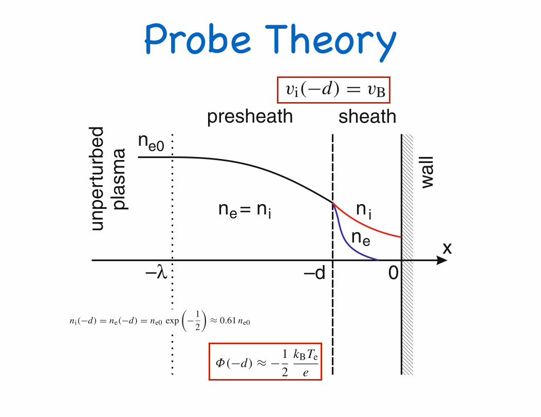
Fig. 7.1 Geometry of theplasma-wall boundary layer.A space charge sheath ofthickness d with ne < ni isformed at the wall. Thematching between sheath andbulk plasma occurs in aquasi-neutral presheath of asize comparable to the ionmean free path λ
x
sheath
wal
l
unpe
rtur
bed
plas
ma
presheath
–d–λ 0
n
nn
e0
e
e iin = n
This simple picture gives us an impression why all isolated bodies inside a plasmacharge up negatively. This applies to the fine metal wires which Langmuir intro-duced as probes into the plasma, to satellites in the Earth’s plasmasphere, or to dustparticles in a plasma. Of course, the real situation is more complex because we willsee that the ion flux to a negative body (except for the very first moment) is notdetermined by the ion thermal velocity. Moreover, we may have neglected otherprocesses that lead to charging. In the case of satellites, these processes are pho-toemission from solar UV-radiation or secondary emission by impact of energeticparticles. We will discuss these effects in Sect. 10.1.
For completeness, we introduce a transition layer adjacent to the sheath, calledthe presheath, that matches the conditions between the space charge sheath and theunpertubed plasma. The presheath will be quasineutral, but the densities of electronsand ions will depend on position, and the ion drift velocity will be non-zero. Thistransition region has a thickness of roughly one ion mean free path.
7.2 The Child-Langmuir Law
Here, we consider a situation, where a potential difference between the wall atΦ(0)
and the sheath edge at Φ(−d) is determined by an external voltage applied to thewall. We are mostly interested in cases where this potential difference creates ahigh potential barrier for thermal electrons |Φ(0) − Φ(−d)| ≫ kBTe/e. Then theBoltzmann factor for the electron gas,
ne(x) = ne(−d) exp!
e[Φ(x) −Φ(−d)]kBTe
", (7.1)
ensures that only few electrons can overcome the barrier, and that a significantnumber of electrons is only found close to the sheath edge. In other words, forlarge negative voltages applied to the wall, most of the sheath will be a pure ionsheath. For simplicity of the calculation, we will completely ignore the electronspace charge for the moment.
176 7 Plasma Boundaries
In conclusion, the ion motion in a quasineutral presheath requires that vi ≤ vB.Hence, this is a second Bohm criterion, which follows from the conditions on thepresheath side of the sheath edge, while the condition on the sheath side requiredvi ≥ vB. Therefore, the complete Bohm criterion for the ion speed at the sheathedge can only be fulfilled by a unique velocity, the Bohm velocity,
vi(−d) = vB , (7.24)
or, in other words, the Mach number has to be M = 1.Does the singularity in the electric field mean that there is also a singularity in
the electric potential? The answer is no. On its way from the plasma bulk throughthe presheath, an ion has gained the kinetic energy 1
2 miv2B = 1
2 kBTe. Neglecting theenergy dissipated in ion-neutral collisions, the potential at the sheath edge can beestimated from energy conservation as
Φ(−d) ≈ −12
kBTe
e. (7.25)
Accordingly, the plasma density at the sheath edge is reduced to
ni(−d) = ne(−d) = ne0 exp!
−12
"≈ 0.61 ne0 . (7.26)
7.4 The Plane Langmuir Probe
In 1925, Mott-Smith and Langmuir [145] had introduced small additional electrodesinto a plasma and studied its volt-ampere characteristic. These Langmuir probes arewidely used in plasma physics because of their simple construction and versatility.We will show below, how the probe characteristic can be used to determine theelectron density and electron temperature of a plasma.
The fundamental electric circuit of a Langmuir probe measurement is shown inFig. 7.3a. A small plane electrode is inserted into a gas discharge. The dischargetube is typically operated from a high-voltage supply via a current-limiting seriesresistor Rs. The probe is biased by an external voltage that is applied between theprobe and a suitable electrode. For reasons of lab safety, this electrode must beproperly grounded. Likewise, the power supply must be able to operate in a modewhere the negative output is the “hot lead” and the positive output grounded. Inthis case, the anode (positive electrode) was chosen because the voltage drop in theanode layer is usually much smaller than that in the cathode (negative electrode)layer (see Chap. 11). A voltmeter gives the probe bias voltage Up and a currentmeter the probe current Ip.
A modern realisation of the circuit for recording probe characteristics with acomputer is shown in Fig. 7.3b. The bias voltage is generated by a digital-to-analog

a set of model plasma parameters. A link is provided to aprogram that allows the user to input the plasma and probeparameters !density, temperature, plasma potential, andprobe dimension" and plot the resulting Langmuir I-V char-acteristic. Section III provides two examples of real Lang-muir probe I-V characteristics obtained in laboratory plas-mas. I close in Sec. IV with comments advocating theinclusion of plasma experiments in the undergraduate ad-vanced laboratory course.
II. MODEL LANGMUIR PROBE CURRENT-VOLTAGE CHARACTERISTICS
In this section I discuss some of the basic aspects of Lang-muir probe theory that are needed to construct model probeI-V characteristics. Two examples of ideal probe I-V charac-teristics are then given. Finally, a discussion of how the idealcharacteristics must be modified to account for real probeeffects is presented.
A. Ion and electron currents to a Langmuir probe1. The ion current
When the bias voltage VB, on the probe is sufficientlynegative with respect to the plasma potential VP, the probe
collects the ion saturation current Iis. Positive ions continueto be collected by the probe until the bias voltage reaches VP,at which point ions begin to be repelled by the probe. ForVB≫VP, all positive ions are repelled, and the ion current tothe probe vanishes, Ii=0. For a Maxwellian ion distributionat the temperature Ti, the dependence of the ion currentIi!VB" !usually taken to be the negative current" on VB isgiven by10
Ii!VB" = #− Iis exp$e!VP − VB"/kTi% , VB ! VP,
− Iis, VB " VP,!1"
where e is the electron’s charge, and k is the Boltzmannconstant. When Ti is comparable to the electron temperatureTe, the ion saturation current, Iis is given by4
Iis =14
enivi,thAprobe, !2"
where, ni is the ion density, vi,th=&8kTi /#mi is the ion ther-mal speed, mi is the ion mass, and Aprobe is the probe collect-ing area. When Te≫Ti,
11 the ion saturation current is notdetermined by the ion thermal speed, but rather is given bythe Bohm ion current3,4,12
Iis = IBohm = 0.6eni&kTe
miAprobe. !3"
The fact that the ion current is determined by the electrontemperature when Te≫Ti is counterintuitive and requiressome explanation. The physical reason for the dependenceIis'!kTe /mi"1/2 has to do with the formation of a sheatharound a negatively biased probe.12,13 If an electrode in aplasma has a potential different from the local plasma poten-tial, the electrons and ions distribute themselves spatiallyaround the electrode in order to limit, or shield, the effect ofthis potential on the bulk plasma. A positively biased elec-trode acquires an electron shielding cloud surrounding it,while a negatively biased electrode acquires a positive spacecharge cloud. For a negatively biased electrode, the charac-teristic shielding distance of the potential disturbance is theelectron Debye length14
$De = (%okTe
e2ne)1/2
. !4"
In the vicinity of a negatively biased probe, both theelectron and ion densities decrease as the particles ap-proach the probe, but not at the same rate. The electrondensity decreases because electrons are repelled by theprobe. In contrast, the ions are accelerated toward theprobe, and due to the continuity of the current density, theion density decreases. A positive space charge sheath canform only if the ion density exceeds the electron density atthe sheath edge, and for the ion density to decrease moreslowly than the electron density, the ions must approachthe sheath with a speed exceeding the Bohm velocity uB= !kTe /mi"1/2.13,15 To achieve this speed, the ions must ac-quire an energy corresponding to a potential drop of0.5!kTe /e", which occurs over a long distance in theplasma. The factor of 0.6 in Eq. !3" is due to the reductionin the density of the ions in the presheath, which is theregion over which the ions are accelerated up to the Bohmspeed.
Fig. 1. Schematic of basic devices for producing a plasma. !a" A dischargetube in which a plasma is formed in a low pressure gas !"1 Torr" byapplying several hundred volts across the cathode and anode. A cylindrical!wire" probe is inserted into the discharge to measure the properties of theplasma. !b" Schematic of a multidipole hot filament plasma device with aLangmuir disk probe. The plasma is produced by electron impact ionizationof argon atoms by electrons that are thermionically emitted and acceleratedfrom a hot tungsten !W" filament. To enhance the ionization efficiency, thewalls of the chamber are lined with rows of permanent magnetic of oppositepolarity. The lower diagram is an end view showing the arrangement ofmagnets. The magnetic field lines are sketched as the dotted curves. In thismagnetic cusp configuration, the bulk plasma is essentially magneticfield-free.
1079 1079Am. J. Phys., Vol. 75, No. 12, December 2007 Robert L. Merlino
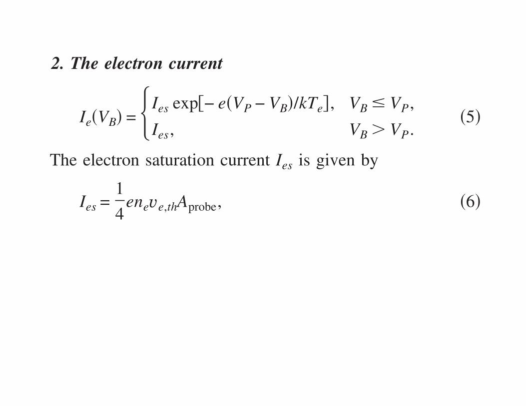
2. The electron current
For VB≫VP the probe collects electron saturation currentIes. For VB!VP the electrons are partially repelled by theprobe, and for a Maxwellian electron velocity distribution,the electron current decreases exponentially with decreasingV. For VB≪VP all electrons are repelled, so that Ie=0. Theelectron current as a function of VB can be expressed as
Ie!VB" = #Ies exp$− e!VP − VB"/kTe% , VB " VP,
Ies, VB # VP.!5"
The electron saturation current Ies is given by
Ies =14
eneve,thAprobe, !6"
where ne is the electron density, ve,th&'8kTe /$me is theelectron thermal speed, and me is the electron mass. We seefrom Eqs. !2", !3", and !6" that because ne=ni and me≪mi,the electron saturation current will be much greater thanthe ion saturation current. For example, in an argon plasmafor Te≫Ti we see from Eqs. !3" and !6" that Ies / Iis
='mi /me / !0.6'2$"=271/1.5=180.
B. Examples of Langmuir probe characteristic1. The ideal Langmuir probe characteristic
For the values in Table I, with Aprobe=2$!dprobe/2"2
=1.41%10−5 m2 for a planar disk probe that collects fromboth sides, we find from Eqs. !3" and !6", Iis=0.03 mA andIes=5.4 mA, so that Ies / Iis=180. The I-V characteristic cor-responding to these parameters is shown in Fig. 2. The cal-culations of the ion current, Eq. !1", the electron current, Eq.!5", and the total current I!VB"= Ie!VB"+ Ii!VB" for the I-Vcurve in Fig. 2 were performed using the Maple procedurefunction and the standard plotting command.16 Alternately,the data for the I-V curve could be computed and plotted ina spreadsheet program. The heavy solid curve in Fig. 2 is thetotal probe current; the electron current !positive" and ioncurrent !negative" are also indicated. The ion current is mag-nified by a factor of 20 in order to see its contribution to thetotal current. Because the electron current is much largerthan the ion current, it is necessary to bias the probe to verynegative voltages to even see the ion current. The total cur-rent is also displayed on a magnified scale !%20" to show theprobe bias at which the total current is zero. The probe biasfor which I!VB=Vf"= Ie+ Ii=0 is the probe’s floating poten-tial, which occurs at Vf (−9.5 V. The floating potential can
be calculated from Eqs. !1"–!5", as the bias voltage at whichIi!Vf"+ Ie!Vf"=0,
Ies exp$e!Vf − VP"/kTe% = Iis, !7"
or
Vf = VP + ) kTe
e*ln)0.6'2$me
mi* . !8"
If the appropriate parameters are inserted into Eq. !6", wefind that Vf =VP−5.2Te, or Vf =−9.4 V for !kTe /e"=2 V, cor-responding to an electron temperature of 2 eV.
The nature of the Langmuir probe I-V characteristic of thetype shown in Fig. 2 is dominated by the fact that the speedof the electrons is considerably higher than that of the posi-tive ions. As a consequence, it is impossible to use the probeto determine the ion temperature, whereas the electron tem-perature can be easily found from the portion of the charac-teristic corresponding to electron repulsion, that is, for VB!VP.
2. Probe I-V characteristic for a positive ion (+) /negativeion (−) plasma with m+=m− and T+=T−
Consider constructing the I-V characteristic in a plasmaconsisting of positive and negative ions of equal mass andtemperatures, for example. In this case because the thermalspeeds of the positive and negative plasma constituents areidentical, we expect that VP=Vf =0, and I+s= I−s. An exampleof such an interesting plasma would be an electron-positronplasma.17 The probe I-V characteristic for this case is shownin Fig. 3, where arbitrary !but equal" values of the saturationcurrents are used. An important point to take from a consid-eration of the I-V plot in Fig. 3 is that the part of the curvewhere the negative ions are repelled !VB!VP" occurs at−10 V!VB!0 V, and the portion corresponding to positiveion repulsion is 0 V!VB!10 V. To find the negative ioncurrent the positive ion saturation current must be used as thebaseline !and not the I=0 line" and vice versa to obtain thepositive ion current. The line extrapolated from the ion cur-
Table I. Parameters of a typical laboratory plasma used to construct an idealLangmuir probe volt-ampere characteristic.
Parameter Symbol Value Units
Ion species Ar+
Ion mass mi 6.7%10−26 kgElectron density ne 1.0%1016 m−3
Ion density ni 1.0%1016 m−3
Electron temperature Te 2.0 eVIon temperature Ti 0.1 eVPlasma potential VP 1.0 VProbe diameter dprobe 3.0 mm
Fig. 2. Ideal Langmuir probe current-voltage characteristic !heavy line" fora model plasma with the parameters listed in Table I. The individual electronand ion currents that are used to construct the full characteristic are alsoshown. The dotted line is the full probe characteristic magnified by a factorof 20 so that the probe floating potential, Vf !the probe voltage where I=0"can be easily determined.
1080 1080Am. J. Phys., Vol. 75, No. 12, December 2007 Robert L. Merlino
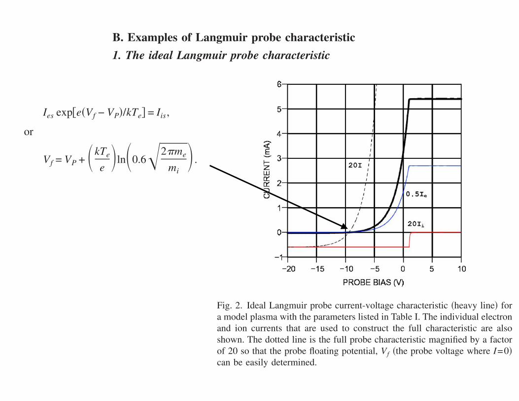
rent should also be used as the baseline to determine theelectron current for the case shown in Fig. 2, although in thatcase the positive ion contribution is negligible, and the I=0line can usually be used to measure Ie. When the plasmacontains a significant fraction of high energy !tens of elec-tron volts" ionizing primary electrons in addition to the sec-ondary electrons resulting from ionization, it is essential tofirst subtract the ion current from the total current to obtainaccurate values of the electron current.
C. Effect of sheath expansion on probe characteristics
The sharp knee at the plasma potential !VP=1.0 V" in theI-V characteristic and flat electron and ion saturation currentsshown in Fig. 3 are ideal probe features that are rarely seenin practice. For this reason the I-V characteristic in Fig. 1 isideal. Real Langmuir probe I-V characteristics have roundedknees and saturation currents that increase gradually withincreasing voltage. The lack of saturation is related to thefact that a sheath13–15 is formed around the probe, and thissheath expands with increasing bias voltage. Sheaths formaround any electrode in a plasma if the bias voltage differsfrom VP. The formation of a sheath is the plasma’s way ofmaintaining charge neutrality in the bulk of the plasma. Anelectrode with a positive bias !relative to VP" attracts an elec-tron cloud to limit the penetration of the electric field into theplasma to a distance approximately equal to the electron De-bye length, !De, defined in Eq. !4". If the plasma density isgreater than #1016 m−3 and Te$2 eV, then the sheath widthwill be "0.1 mm. In this case the expansion of the sheathwill produce only a negligible increase in current as theprobe bias is increased. For lower plasma densities and smallprobes the sheath expansion produces an increase in the col-lected current because the effective area for particle collec-tion is the sheath area and not the geometric probe area.Another way to think about the sheath expansion effect is torealize that for a finite probe, the collection of plasma par-ticles is limited by fact that some particles that enter thesheath will orbit around the probe and not be collected. Asthe potential on the probe is increased, the minimum impactparameter for which particles are collected increases and thusmore particles will be collected.
Sheath expansion occurs for both the ion and electron cur-rents and must be taken into account in the interpretation ofthe I-V characteristics. The sheath expansion effect can beincorporated in the ideal probe characteristic so that we canlearn how to deal with it when interpreting real Langmuirprobe characteristics. An illustration of this effect is shown inFig. 4. The parameters used to produce this I-V characteristicwere VP=4 V, Ies=100Iis ,Te=4 eV, and Ti=0.1 eV. Thesheath expansion was modeled as a linear function of thebias voltage with Iis!VB"=−%0.2!VP−VB"+ Iis& for VB#VP forthe ions, and Ies!VB"=0.7!VB−VP"+ Ies for VB$VP for theelectrons. Figure 4!a" shows the full I-V characteristic. Realcharacteristics rarely show the sharp knee at the plasma po-tential; rather the knee tends to be rounded !as illustrated bythe dotted curve" due to the presence of oscillations of theplasma potential15 or averaging in the data acquisition oranalysis process. The rounding of the knee complicates thedetermination of the electron saturation current, but the loca-tion of the knee is made more evident by replotting the cur-rent on a semilog scale, as shown in Fig. 4!b". Both Ies andVp can now be easily determined as the coordinates of theintersection of two straight lines—one parallel to the curveabove the knee and the other parallel to the sloping part. Theslope of the straight line fit tothe electron current in Fig. 4!b"is used to determine Te, as Te= !V2−V1" / ln!Ie2 / Ie1", where 1and 2 refer to any two points on the line. The electron currentbegins falling off the straight line due to the contribution ofthe ion current. An accurate measurement of the ion currentin this case requires that Ii be obtained for a sufficientlynegative probe bias so that the electron contribution is ex-cluded. The procedure for measuring Iis is shown in Fig.4!c". The ion current is plotted on an expanded scale and astraight line is fitted through the points; Iis is taken as thevalue of Ii at Vp. More accurate methods of dealing with thenonsaturation of the ion current are discussed in Refs. 5, 7, 9,and 18.
III. EXAMPLES OF LANGMUIR PROBECHARACTERISTICS FROM LABORATORYPLASMAS
In this section I provide two examples of Langmuir probeI-V characteristics obtained in more realistic laboratory plas-mas. These examples demonstrate how the basic principlespresented in Sec. II are applied in the interpretation of realcharacteristics.
A. Multidipole plasma
A multidipole device19–21 is a relatively simple setup forproducing a plasma that can be used for basic plasma physicsexperiments. A schematic diagram of a typical multidipoledevice is shown in Fig. 1!b". It is essentially a large !about20 l" stainless steel soup pot !sometimes literally" which ispumped down to a base pressure of #10−6 Torr, and thenfilled with a gas such as argon to a pressure of approximately10−5–10−3 Torr. The plasma is produced by electron emis-sion from a set of tungsten filaments that are biased to anegative potential of approximately 50 V. The thermioni-cally emitted primary electrons that are accelerated from thefilaments ionize the gas producing the plasma. To enhancethe probability that a primary electron will undergo an ion-izing collision with a neutral atom, the walls of the deviceare lined with permanent magnets in rows of opposite polar-
Fig. 3. Langmuir probe I-V characteristic for a plasma with positive andnegative ions of equal mass and temperatures. The positive ion and negativeion currents are also shown.
1081 1081Am. J. Phys., Vol. 75, No. 12, December 2007 Robert L. Merlino

ity creating a magnetic barrier, which inhibits the ionizingelectrons from escaping. Due to the alternating polarity ofthe magnet rows, the magnetic field has substantial strengthonly very close to the walls, so that the main plasma regionis essentially magnetic field free.
A typical Langmuir probe I-V characteristic obtained in
the multidipole device in the University of Iowa’s under-graduate Advanced Physics Lab is shown in Fig. 5. Thischaracteristic was taken with a 6 mm diameter planar diskprobe in an argon plasma at a pressure of 0.5 mTorr. The topcurve !Fig. 5"a#$ is the positive probe current due to electroncollection. As discussed in Sec. II "see Fig. 4#, the electroncurrent continues to increase slightly with increasing voltageabove the plasma potential due to the sheath expansion ef-fect. The determination of the electron saturation current andplasma potential is facilitated by replotting the current on asemilog scale as shown in Fig. 5"b#. The break point occursat VP%4 V, with Ies= "100±5# mA. The slope of the down-ward portion of the line on the semilog plot gives Te%1.5 eV. The negative "ion# current is shown on an ex-panded scale in Fig. 5"c#. Again we see the sheath expansioneffect as the "negative# probe voltage increases. The ion satu-ration current is estimated by extrapolating the linear portionof the ion current to the plasma potential, where Ii"VP#= "0.85±0.05# mA. The floating potential is also found fromFig. 5"c# as Vf"I=0#%−5 V. The ion and electron densitiescan now be calculated using Eqs. "2# and "4# with Te=1.5 eV. We find that ni= "8.3±0.5#!1016 m−3, and ne= "5.5±0.55#!1016 m−3. Even taking into account the uncer-tainties involved in measuring the saturation currents fromthe plots, there remains a &25% difference between theplasma density obtained from the ion and electron currents.This difference is a typical occurrence with Langmuir probesmeasurements. In a magnetized plasma, the discrepancy inthe densities obtained from the electron and ion saturation
Fig. 4. Model Langmuir probe I-V characteristic including the effect ofsheath expansion, computed with VP=4 V, Te=4 eV, Ti=0.1 eV, andIes / Iis=200. "a# Total current. The dotted curve depicts the rounding of theknee due to plasma noise or averaging effects. "b# log I"VB# versus VB. Theintersection of the horizontal and vertical dotted lines occurs at the coordi-nates "VP , Ies#. The electron temperature is obtained from the slope of thelinear part of the downward sloping portion of this curve. "c# Expanded viewof the ion current. The sloping dotted line is a linear fit to the ion current.The ion saturation current is found by extrapolating this line to the plasmapotential.
Fig. 5. Langmuir probe I-V characteristic obtained in a multidipole plasmain argon at a pressure of 0.5 mTorr. "a# Electron current. "b# log I"VB# versusVB. The semilog plot of the electron current provides a clear demarcation ofthe plasma potential and electron saturation current. Te is found from theslope of the exponentially decreasing portion. "c# Expanded scale view ofthe ion current used to find Iis.
1082 1082Am. J. Phys., Vol. 75, No. 12, December 2007 Robert L. Merlino
a set of model plasma parameters. A link is provided to aprogram that allows the user to input the plasma and probeparameters !density, temperature, plasma potential, andprobe dimension" and plot the resulting Langmuir I-V char-acteristic. Section III provides two examples of real Lang-muir probe I-V characteristics obtained in laboratory plas-mas. I close in Sec. IV with comments advocating theinclusion of plasma experiments in the undergraduate ad-vanced laboratory course.
II. MODEL LANGMUIR PROBE CURRENT-VOLTAGE CHARACTERISTICS
In this section I discuss some of the basic aspects of Lang-muir probe theory that are needed to construct model probeI-V characteristics. Two examples of ideal probe I-V charac-teristics are then given. Finally, a discussion of how the idealcharacteristics must be modified to account for real probeeffects is presented.
A. Ion and electron currents to a Langmuir probe1. The ion current
When the bias voltage VB, on the probe is sufficientlynegative with respect to the plasma potential VP, the probe
collects the ion saturation current Iis. Positive ions continueto be collected by the probe until the bias voltage reaches VP,at which point ions begin to be repelled by the probe. ForVB≫VP, all positive ions are repelled, and the ion current tothe probe vanishes, Ii=0. For a Maxwellian ion distributionat the temperature Ti, the dependence of the ion currentIi!VB" !usually taken to be the negative current" on VB isgiven by10
Ii!VB" = #− Iis exp$e!VP − VB"/kTi% , VB ! VP,
− Iis, VB " VP,!1"
where e is the electron’s charge, and k is the Boltzmannconstant. When Ti is comparable to the electron temperatureTe, the ion saturation current, Iis is given by4
Iis =14
enivi,thAprobe, !2"
where, ni is the ion density, vi,th=&8kTi /#mi is the ion ther-mal speed, mi is the ion mass, and Aprobe is the probe collect-ing area. When Te≫Ti,
11 the ion saturation current is notdetermined by the ion thermal speed, but rather is given bythe Bohm ion current3,4,12
Iis = IBohm = 0.6eni&kTe
miAprobe. !3"
The fact that the ion current is determined by the electrontemperature when Te≫Ti is counterintuitive and requiressome explanation. The physical reason for the dependenceIis'!kTe /mi"1/2 has to do with the formation of a sheatharound a negatively biased probe.12,13 If an electrode in aplasma has a potential different from the local plasma poten-tial, the electrons and ions distribute themselves spatiallyaround the electrode in order to limit, or shield, the effect ofthis potential on the bulk plasma. A positively biased elec-trode acquires an electron shielding cloud surrounding it,while a negatively biased electrode acquires a positive spacecharge cloud. For a negatively biased electrode, the charac-teristic shielding distance of the potential disturbance is theelectron Debye length14
$De = (%okTe
e2ne)1/2
. !4"
In the vicinity of a negatively biased probe, both theelectron and ion densities decrease as the particles ap-proach the probe, but not at the same rate. The electrondensity decreases because electrons are repelled by theprobe. In contrast, the ions are accelerated toward theprobe, and due to the continuity of the current density, theion density decreases. A positive space charge sheath canform only if the ion density exceeds the electron density atthe sheath edge, and for the ion density to decrease moreslowly than the electron density, the ions must approachthe sheath with a speed exceeding the Bohm velocity uB= !kTe /mi"1/2.13,15 To achieve this speed, the ions must ac-quire an energy corresponding to a potential drop of0.5!kTe /e", which occurs over a long distance in theplasma. The factor of 0.6 in Eq. !3" is due to the reductionin the density of the ions in the presheath, which is theregion over which the ions are accelerated up to the Bohmspeed.
Fig. 1. Schematic of basic devices for producing a plasma. !a" A dischargetube in which a plasma is formed in a low pressure gas !"1 Torr" byapplying several hundred volts across the cathode and anode. A cylindrical!wire" probe is inserted into the discharge to measure the properties of theplasma. !b" Schematic of a multidipole hot filament plasma device with aLangmuir disk probe. The plasma is produced by electron impact ionizationof argon atoms by electrons that are thermionically emitted and acceleratedfrom a hot tungsten !W" filament. To enhance the ionization efficiency, thewalls of the chamber are lined with rows of permanent magnetic of oppositepolarity. The lower diagram is an end view showing the arrangement ofmagnets. The magnetic field lines are sketched as the dotted curves. In thismagnetic cusp configuration, the bulk plasma is essentially magneticfield-free.
1079 1079Am. J. Phys., Vol. 75, No. 12, December 2007 Robert L. Merlino
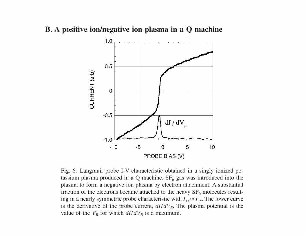
currents is considerably larger, but expected. The gyroradiusof the electrons is typically much smaller than that of theions so that the collection of electrons is affected more thanthe collection of ions. In that case, measurements of theplasma density using the ion saturation current are more re-liable.
It is interesting to calculate the fraction of the neutral ar-gon atoms that are actually ionized in the plasma using themeasured value of the plasma density. This fraction is knownas the percent ionization or ionization fraction. The densityof the neutral argon atoms is na= P /kTg, where Tg is thetemperature of the neutral gas, and P is the neutral gas pres-sure. For P=5!10−4 Torr and Tgas!300 K, na=1.65!1019 m−3. With ni=8!1016 m−3, we obtain ni /na=0.005.Thus, only 0.5% of the neutral atoms are ionized.
The fact that the neutral density is roughly 1000 times theplasma density might lead one to wonder about the role ofthese neutral atoms on the plasma and probe measurements.To access the possible effects of collisions of the ions andelectrons with neutrals, we need to estimate a few typicalcollision mean free paths, "= "na##−1, where # is the crosssection22 for the particular process considered. For ioniza-tion, #ionz!8!10−20 m2 "for 50 eV electrons on argon#, so"ionz$75 cm. Thus "ionz is on the order of the dimensions ofa typical laboratory plasma device. The relatively long ion-ization mean free path explains, in part, the relatively lowvalue of the ionization percentage—electrons that are ener-getically capable of ionizing atoms are more likely to make itto the wall before ionizing an atom.
The purpose of the magnets on the walls of the multidi-pole device is to reflect the ionizing electrons back into theplasma, thus increasing their chances of having an ionizingcollision. Electrons can also make elastic collisions with neu-tral atoms; a typical cross section in this case is #en$10−20 m2, giving "en$6 m. For collisions between theions and neutral atoms, the most important process to con-sider is charge exchange, Ar++Ar→Ar+Ar+, in which anargon ion exchanges an electron with an argon atom, result-ing in the production of very slow argon ions and argonatoms with an energy practically equal to the initial energy ofthe ions. The cross section for this process is #in$5!10−19 m2, giving "in$12 cm.
We note that for all of the processes considered the meanfree paths are much greater than the probe size and theshielding distance or sheath size, so that even though theneutral density far exceeds the plasma density, the neutralgas atoms produce negligible effects on the probe measure-ments.
B. A positive ion/negative ion plasma in a Q machine
Figure 3 is an example of a Langmuir probe I-V charac-teristic in a plasma in which the positive and negative par-ticles have the same mass. This example might appear to beexotic, but it is not difficult to produce a plasma havingalmost equal numbers of positive and negative ions of com-parable mass. We have produced positive ion/negative ionplasmas "also known as electronegative plasmas# in a devicecalled a Q machine.23 In a Q machine the plasma is producedby surface ionization, an effect discovered by Langmuir andKingdon in 1923.24 They found that cesium atoms that comeinto contact with a tungsten filament heated to 1200 Kemerge as cesium ions. The reason is that the ionizing poten-tial of cesium is 3.89 eV, and the work function for tungsten
is 4.52 eV. Surface ionization is exploited in a Q machine23
by directing an atomic beam of cesium or potassium atomsonto a hot "$2000 K# tungsten or tantalum plate, usuallyseveral centimeters in diameter. Both positive ions and ther-mionic electrons emerge from the plate forming a nearlyfully ionized plasma that is confined by a strong"$0.1–0.5 T# longitudinal magnetic field. The relativelygood thermal contact between the plasma and the hot plateresults in a plasma in which both the electrons and positiveions are at roughly the plate temperature, typically 0.2 eV.The Q machine has been used mainly for studying the basicproperties of magnetized plasmas, and in particular plasmawaves. "The Q designation refers to the expectation that athermally produced plasma would be quiescent, that is, rela-tively free of low frequency plasma instabilities.#
Negative ions are readily formed in a Q machine plasmaby leaking into the vacuum chamber sulfur hexafluoride SF6at a pressure $10−5–10−4 Torr. Electrons attach to SF6forming SF6
− negative ions.25 The cross section for electronattachment to SF6 is energy dependent and peaks in the en-ergy range that coincides closely with that of the Q machineelectrons. Under these circumstances it is possible to produceplasmas in which the ratio of electron density to positive iondensity is ne /n+$10−3. A Langmuir probe I-V characteristicobtained in such a K+ /SF6
− "m− /m+=3.7# is shown in Fig. 6.Note that the negative ion "positive current# and positive ion"negative current# saturation currents are comparable. Withsuch a characteristic the plasma potential is most easilydetermined as the voltage at which the first derivative ofthe characteristic is a maximum. In this case we see thatVP%−1 V. The characteristic is roughly symmetric about I=0, with a floating potential Vf !VP, a result that is to beexpected in a plasma with n+!n− and ne≪n+. When thenegative ion and positive ion densities are comparable, itmay even be possible to extract both the negative and posi-tive ion temperatures from the Langmuir characteristic.
Fig. 6. Langmuir probe I-V characteristic obtained in a singly ionized po-tassium plasma produced in a Q machine. SF6 gas was introduced into theplasma to form a negative ion plasma by electron attachment. A substantialfraction of the electrons became attached to the heavy SF6 molecules result-ing in a nearly symmetric probe characteristic with I+s! I−s. The lower curveis the derivative of the probe current, dI /dVB. The plasma potential is thevalue of the VB for which dI /dVB is a maximum.
1083 1083Am. J. Phys., Vol. 75, No. 12, December 2007 Robert L. Merlino
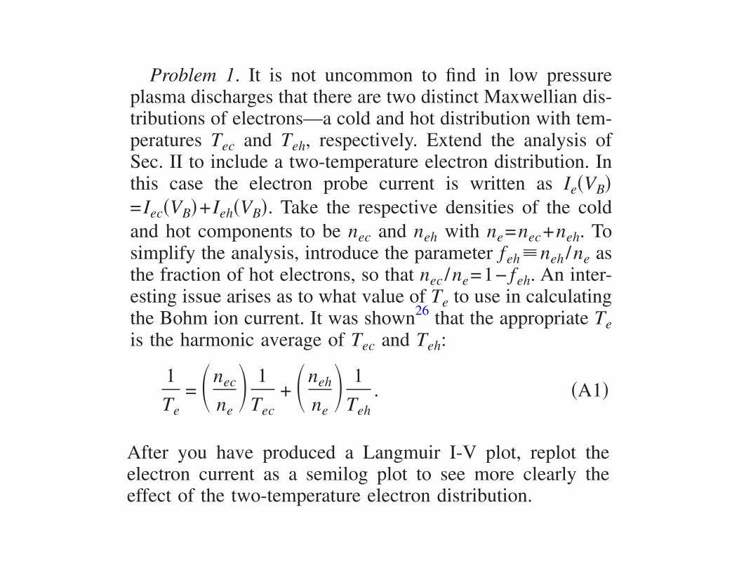
IV. COMMENTS
A Langmuir probe I-V characteristic becomes less confus-ing once we are able to see the individual current contribu-tions as well as the total probe current. The procedure forconstructing an I-V characteristic given an appropriate set ofplasma input parameters has been presented. A MAPLE pro-gram that creates the I-V characteristic is available onEPAPS16 and is also available on the author’s website.
The inclusion of plasma physics experiments in upperlevel advanced laboratory courses for physics majors canprovide students with much exposure to many important top-ics and methods in experimental physics including basicvacuum techniques, vacuum measurement methods, solder-ing, spot welding, brazing, electronic circuit design and fab-rication, data acquisition methods, curve fitting techniques,and instrument design and construction !building a Langmuirprobe". Students also experience using basic concepts in thekinetic theory of gases.
Plasma physics experiments also provide ideal researchtopics for undergraduate thesis projects. For instructors con-templating the inclusion of plasma experiments in advancedlaboratory courses, my suggestion is to start with the basicmultidipole plasma.19–21 This device is relatively simple andinexpensive, with the most costly component being thevacuum pumping system. If money is not a concern, it ispossible to purchase fully operational vacuum systems thatare easily adaptable for plasma production. Although it isnow possible to purchase off the shelf Langmuir probe sys-tems, complete with probe and associated electronics, theexperience of constructing probes from scratch is a valuableone that should not be avoided. Building a probe is often thefirst instance in which students are required to use theirhands to create an experimental instrument. Far too oftenstudents are left with the impression that everything neededto perform a measurement can be found at manufacturers’web sites.
ACKNOWLEDGMENT
This work was supported by the U.S. Department ofEnergy Grant DE-FG02-04ER54795.
APPENDIX: SUGGESTED PROBLEMSFOR FURTHER STUDY
The following two problems are intended to extend thebasic probe theory to include some other important effectsoften encountered in using Langmuir probes in realistic plas-mas.
Problem 1. It is not uncommon to find in low pressureplasma discharges that there are two distinct Maxwellian dis-tributions of electrons—a cold and hot distribution with tem-peratures Tec and Teh, respectively. Extend the analysis ofSec. II to include a two-temperature electron distribution. Inthis case the electron probe current is written as Ie!VB"= Iec!VB"+ Ieh!VB". Take the respective densities of the coldand hot components to be nec and neh with ne=nec+neh. Tosimplify the analysis, introduce the parameter feh#neh /ne asthe fraction of hot electrons, so that nec /ne=1− feh. An inter-esting issue arises as to what value of Te to use in calculatingthe Bohm ion current. It was shown26 that the appropriate Teis the harmonic average of Tec and Teh:
1Te
= $nec
ne% 1
Tec+ $neh
ne% 1
Teh. !A1"
After you have produced a Langmuir I-V plot, replot theelectron current as a semilog plot to see more clearly theeffect of the two-temperature electron distribution.
Problem 2. In plasmas produced in hot-filament dis-charges, the effect of the ionizing !primary" electrons on theprobe I-V trace can be observed, particularly at neutral pres-sures below &10−4 Torr. Extend the probe analysis to in-clude the presence of these energetic primary electrons,which can be modeled as an isotropic monoenergetic distri-bution. Express the total electron current as Iet!VB"= Ie!VB"+ Iep!VB", where Ie!VB" is the contribution from the bulk elec-trons, and Iep!VB" is the primary electron contribution, whichfor an isotropic monoenergetic distribution is3
Iep
='Iep* #
14
enepvepAprobe, VB ! VP,
Iep* (1 −
2e!VP − VB"mevep
2 ) , $Vp −mevep
2
2e% " VB " VP,
0, VB " $VP −mevep
2
2e% ,
*!A2"
where nep is the density of primary electrons, and vep
=+2Ep /me is the speed of the primary electrons with energyEp. To produce an I-V plot, assume that the primary electronsare accelerated through a potential drop &50–60 V, and thedensity is in the range of !0.001–0.1"ne.
a"Electronic mail: [email protected] is common in plasma physics to give temperatures in equivalent energyunits !eV". For example, we say that Te=2 eV, which means we are reallygiving kTe converted to electron volts. The actual temperature corre-sponding to 1 eV is 11,600 K.
2I. Langmuir and H. Mott-Smith, “The theory of collectors in gaseousdischarges,” Phys. Rev. 28, 727–763 !1926".
3I suggest that Langmuir probe novices start by reading Noah Hershkow-itz’s article, “How Langmuir probes work,” in Plasma Diagnostics, Dis-charge Parameters and Chemistry, edited by O. Auciello and D. L.Flamm !Academic, Boston, 1989", Vol. 1, Chap. 3.
4B. E. Cherrington, “The use of Langmuir probes for plasma diagnostics:A review,” Plasma Chem. Plasma Process. 2, 113–140 !1982".
5F. F. Chen, “Electric Probes,” in Plasma Diagnostic Techniques, edited byR. H. Huddlestone and S. L. Leonard !Academic, New York, 1965",Chap. 4. A concise summary of Langmuir probe techniques by F. F. Chen,“Lecture notes on Langmuir probe diagnostics” is available at,www.ee.ucla.edu/~ffchen/Publs/Chen210R.pdf-.
6L. Schott, “Electrical probes,” in Plasma Diagnostics, edited by W.Lochte-Holtgreven !North-Holland, Amsterdam, 1968", Chap. 11.
7J. D. Swift and M. J. R. Schwar, Electrical Probes for Plasma Diagnos-tics !American Elsevier, New York, 1969".
8I. H. Hutchinson, Principles of Plasma Diagnostics, 2nd ed. !CambridgeU.P., Cambridge, 2002", Chap. 3.
9J. G. Laframboise, “Theory of spherical and cylindrical Langmuir probesin a collisionless, Maxwellian plasma,” Univ. Toronto Aerospace StudiesReport No. 11 !1966".
10Reference 3, p. 118.11 It is common in discharge plasmas to have Ti#Te due to the fact that the
ions are created from neutral atoms at room temperature, while the elec-trons are considerable hotter !by a factor of about 100" because they must
1084 1084Am. J. Phys., Vol. 75, No. 12, December 2007 Robert L. MerlinoIV. COMMENTS
A Langmuir probe I-V characteristic becomes less confus-ing once we are able to see the individual current contribu-tions as well as the total probe current. The procedure forconstructing an I-V characteristic given an appropriate set ofplasma input parameters has been presented. A MAPLE pro-gram that creates the I-V characteristic is available onEPAPS16 and is also available on the author’s website.
The inclusion of plasma physics experiments in upperlevel advanced laboratory courses for physics majors canprovide students with much exposure to many important top-ics and methods in experimental physics including basicvacuum techniques, vacuum measurement methods, solder-ing, spot welding, brazing, electronic circuit design and fab-rication, data acquisition methods, curve fitting techniques,and instrument design and construction !building a Langmuirprobe". Students also experience using basic concepts in thekinetic theory of gases.
Plasma physics experiments also provide ideal researchtopics for undergraduate thesis projects. For instructors con-templating the inclusion of plasma experiments in advancedlaboratory courses, my suggestion is to start with the basicmultidipole plasma.19–21 This device is relatively simple andinexpensive, with the most costly component being thevacuum pumping system. If money is not a concern, it ispossible to purchase fully operational vacuum systems thatare easily adaptable for plasma production. Although it isnow possible to purchase off the shelf Langmuir probe sys-tems, complete with probe and associated electronics, theexperience of constructing probes from scratch is a valuableone that should not be avoided. Building a probe is often thefirst instance in which students are required to use theirhands to create an experimental instrument. Far too oftenstudents are left with the impression that everything neededto perform a measurement can be found at manufacturers’web sites.
ACKNOWLEDGMENT
This work was supported by the U.S. Department ofEnergy Grant DE-FG02-04ER54795.
APPENDIX: SUGGESTED PROBLEMSFOR FURTHER STUDY
The following two problems are intended to extend thebasic probe theory to include some other important effectsoften encountered in using Langmuir probes in realistic plas-mas.
Problem 1. It is not uncommon to find in low pressureplasma discharges that there are two distinct Maxwellian dis-tributions of electrons—a cold and hot distribution with tem-peratures Tec and Teh, respectively. Extend the analysis ofSec. II to include a two-temperature electron distribution. Inthis case the electron probe current is written as Ie!VB"= Iec!VB"+ Ieh!VB". Take the respective densities of the coldand hot components to be nec and neh with ne=nec+neh. Tosimplify the analysis, introduce the parameter feh#neh /ne asthe fraction of hot electrons, so that nec /ne=1− feh. An inter-esting issue arises as to what value of Te to use in calculatingthe Bohm ion current. It was shown26 that the appropriate Teis the harmonic average of Tec and Teh:
1Te
= $nec
ne% 1
Tec+ $neh
ne% 1
Teh. !A1"
After you have produced a Langmuir I-V plot, replot theelectron current as a semilog plot to see more clearly theeffect of the two-temperature electron distribution.
Problem 2. In plasmas produced in hot-filament dis-charges, the effect of the ionizing !primary" electrons on theprobe I-V trace can be observed, particularly at neutral pres-sures below &10−4 Torr. Extend the probe analysis to in-clude the presence of these energetic primary electrons,which can be modeled as an isotropic monoenergetic distri-bution. Express the total electron current as Iet!VB"= Ie!VB"+ Iep!VB", where Ie!VB" is the contribution from the bulk elec-trons, and Iep!VB" is the primary electron contribution, whichfor an isotropic monoenergetic distribution is3
Iep
='Iep* #
14
enepvepAprobe, VB ! VP,
Iep* (1 −
2e!VP − VB"mevep
2 ) , $Vp −mevep
2
2e% " VB " VP,
0, VB " $VP −mevep
2
2e% ,
*!A2"
where nep is the density of primary electrons, and vep
=+2Ep /me is the speed of the primary electrons with energyEp. To produce an I-V plot, assume that the primary electronsare accelerated through a potential drop &50–60 V, and thedensity is in the range of !0.001–0.1"ne.
a"Electronic mail: [email protected] is common in plasma physics to give temperatures in equivalent energyunits !eV". For example, we say that Te=2 eV, which means we are reallygiving kTe converted to electron volts. The actual temperature corre-sponding to 1 eV is 11,600 K.
2I. Langmuir and H. Mott-Smith, “The theory of collectors in gaseousdischarges,” Phys. Rev. 28, 727–763 !1926".
3I suggest that Langmuir probe novices start by reading Noah Hershkow-itz’s article, “How Langmuir probes work,” in Plasma Diagnostics, Dis-charge Parameters and Chemistry, edited by O. Auciello and D. L.Flamm !Academic, Boston, 1989", Vol. 1, Chap. 3.
4B. E. Cherrington, “The use of Langmuir probes for plasma diagnostics:A review,” Plasma Chem. Plasma Process. 2, 113–140 !1982".
5F. F. Chen, “Electric Probes,” in Plasma Diagnostic Techniques, edited byR. H. Huddlestone and S. L. Leonard !Academic, New York, 1965",Chap. 4. A concise summary of Langmuir probe techniques by F. F. Chen,“Lecture notes on Langmuir probe diagnostics” is available at,www.ee.ucla.edu/~ffchen/Publs/Chen210R.pdf-.
6L. Schott, “Electrical probes,” in Plasma Diagnostics, edited by W.Lochte-Holtgreven !North-Holland, Amsterdam, 1968", Chap. 11.
7J. D. Swift and M. J. R. Schwar, Electrical Probes for Plasma Diagnos-tics !American Elsevier, New York, 1969".
8I. H. Hutchinson, Principles of Plasma Diagnostics, 2nd ed. !CambridgeU.P., Cambridge, 2002", Chap. 3.
9J. G. Laframboise, “Theory of spherical and cylindrical Langmuir probesin a collisionless, Maxwellian plasma,” Univ. Toronto Aerospace StudiesReport No. 11 !1966".
10Reference 3, p. 118.11 It is common in discharge plasmas to have Ti#Te due to the fact that the
ions are created from neutral atoms at room temperature, while the elec-trons are considerable hotter !by a factor of about 100" because they must
1084 1084Am. J. Phys., Vol. 75, No. 12, December 2007 Robert L. Merlino
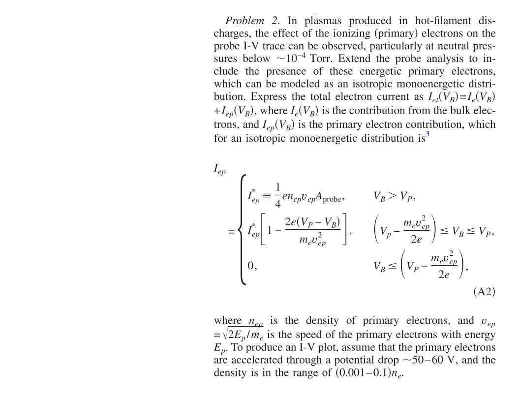
IV. COMMENTS
A Langmuir probe I-V characteristic becomes less confus-ing once we are able to see the individual current contribu-tions as well as the total probe current. The procedure forconstructing an I-V characteristic given an appropriate set ofplasma input parameters has been presented. A MAPLE pro-gram that creates the I-V characteristic is available onEPAPS16 and is also available on the author’s website.
The inclusion of plasma physics experiments in upperlevel advanced laboratory courses for physics majors canprovide students with much exposure to many important top-ics and methods in experimental physics including basicvacuum techniques, vacuum measurement methods, solder-ing, spot welding, brazing, electronic circuit design and fab-rication, data acquisition methods, curve fitting techniques,and instrument design and construction !building a Langmuirprobe". Students also experience using basic concepts in thekinetic theory of gases.
Plasma physics experiments also provide ideal researchtopics for undergraduate thesis projects. For instructors con-templating the inclusion of plasma experiments in advancedlaboratory courses, my suggestion is to start with the basicmultidipole plasma.19–21 This device is relatively simple andinexpensive, with the most costly component being thevacuum pumping system. If money is not a concern, it ispossible to purchase fully operational vacuum systems thatare easily adaptable for plasma production. Although it isnow possible to purchase off the shelf Langmuir probe sys-tems, complete with probe and associated electronics, theexperience of constructing probes from scratch is a valuableone that should not be avoided. Building a probe is often thefirst instance in which students are required to use theirhands to create an experimental instrument. Far too oftenstudents are left with the impression that everything neededto perform a measurement can be found at manufacturers’web sites.
ACKNOWLEDGMENT
This work was supported by the U.S. Department ofEnergy Grant DE-FG02-04ER54795.
APPENDIX: SUGGESTED PROBLEMSFOR FURTHER STUDY
The following two problems are intended to extend thebasic probe theory to include some other important effectsoften encountered in using Langmuir probes in realistic plas-mas.
Problem 1. It is not uncommon to find in low pressureplasma discharges that there are two distinct Maxwellian dis-tributions of electrons—a cold and hot distribution with tem-peratures Tec and Teh, respectively. Extend the analysis ofSec. II to include a two-temperature electron distribution. Inthis case the electron probe current is written as Ie!VB"= Iec!VB"+ Ieh!VB". Take the respective densities of the coldand hot components to be nec and neh with ne=nec+neh. Tosimplify the analysis, introduce the parameter feh#neh /ne asthe fraction of hot electrons, so that nec /ne=1− feh. An inter-esting issue arises as to what value of Te to use in calculatingthe Bohm ion current. It was shown26 that the appropriate Teis the harmonic average of Tec and Teh:
1Te
= $nec
ne% 1
Tec+ $neh
ne% 1
Teh. !A1"
After you have produced a Langmuir I-V plot, replot theelectron current as a semilog plot to see more clearly theeffect of the two-temperature electron distribution.
Problem 2. In plasmas produced in hot-filament dis-charges, the effect of the ionizing !primary" electrons on theprobe I-V trace can be observed, particularly at neutral pres-sures below &10−4 Torr. Extend the probe analysis to in-clude the presence of these energetic primary electrons,which can be modeled as an isotropic monoenergetic distri-bution. Express the total electron current as Iet!VB"= Ie!VB"+ Iep!VB", where Ie!VB" is the contribution from the bulk elec-trons, and Iep!VB" is the primary electron contribution, whichfor an isotropic monoenergetic distribution is3
Iep
='Iep* #
14
enepvepAprobe, VB ! VP,
Iep* (1 −
2e!VP − VB"mevep
2 ) , $Vp −mevep
2
2e% " VB " VP,
0, VB " $VP −mevep
2
2e% ,
*!A2"
where nep is the density of primary electrons, and vep
=+2Ep /me is the speed of the primary electrons with energyEp. To produce an I-V plot, assume that the primary electronsare accelerated through a potential drop &50–60 V, and thedensity is in the range of !0.001–0.1"ne.
a"Electronic mail: [email protected] is common in plasma physics to give temperatures in equivalent energyunits !eV". For example, we say that Te=2 eV, which means we are reallygiving kTe converted to electron volts. The actual temperature corre-sponding to 1 eV is 11,600 K.
2I. Langmuir and H. Mott-Smith, “The theory of collectors in gaseousdischarges,” Phys. Rev. 28, 727–763 !1926".
3I suggest that Langmuir probe novices start by reading Noah Hershkow-itz’s article, “How Langmuir probes work,” in Plasma Diagnostics, Dis-charge Parameters and Chemistry, edited by O. Auciello and D. L.Flamm !Academic, Boston, 1989", Vol. 1, Chap. 3.
4B. E. Cherrington, “The use of Langmuir probes for plasma diagnostics:A review,” Plasma Chem. Plasma Process. 2, 113–140 !1982".
5F. F. Chen, “Electric Probes,” in Plasma Diagnostic Techniques, edited byR. H. Huddlestone and S. L. Leonard !Academic, New York, 1965",Chap. 4. A concise summary of Langmuir probe techniques by F. F. Chen,“Lecture notes on Langmuir probe diagnostics” is available at,www.ee.ucla.edu/~ffchen/Publs/Chen210R.pdf-.
6L. Schott, “Electrical probes,” in Plasma Diagnostics, edited by W.Lochte-Holtgreven !North-Holland, Amsterdam, 1968", Chap. 11.
7J. D. Swift and M. J. R. Schwar, Electrical Probes for Plasma Diagnos-tics !American Elsevier, New York, 1969".
8I. H. Hutchinson, Principles of Plasma Diagnostics, 2nd ed. !CambridgeU.P., Cambridge, 2002", Chap. 3.
9J. G. Laframboise, “Theory of spherical and cylindrical Langmuir probesin a collisionless, Maxwellian plasma,” Univ. Toronto Aerospace StudiesReport No. 11 !1966".
10Reference 3, p. 118.11 It is common in discharge plasmas to have Ti#Te due to the fact that the
ions are created from neutral atoms at room temperature, while the elec-trons are considerable hotter !by a factor of about 100" because they must
1084 1084Am. J. Phys., Vol. 75, No. 12, December 2007 Robert L. Merlino


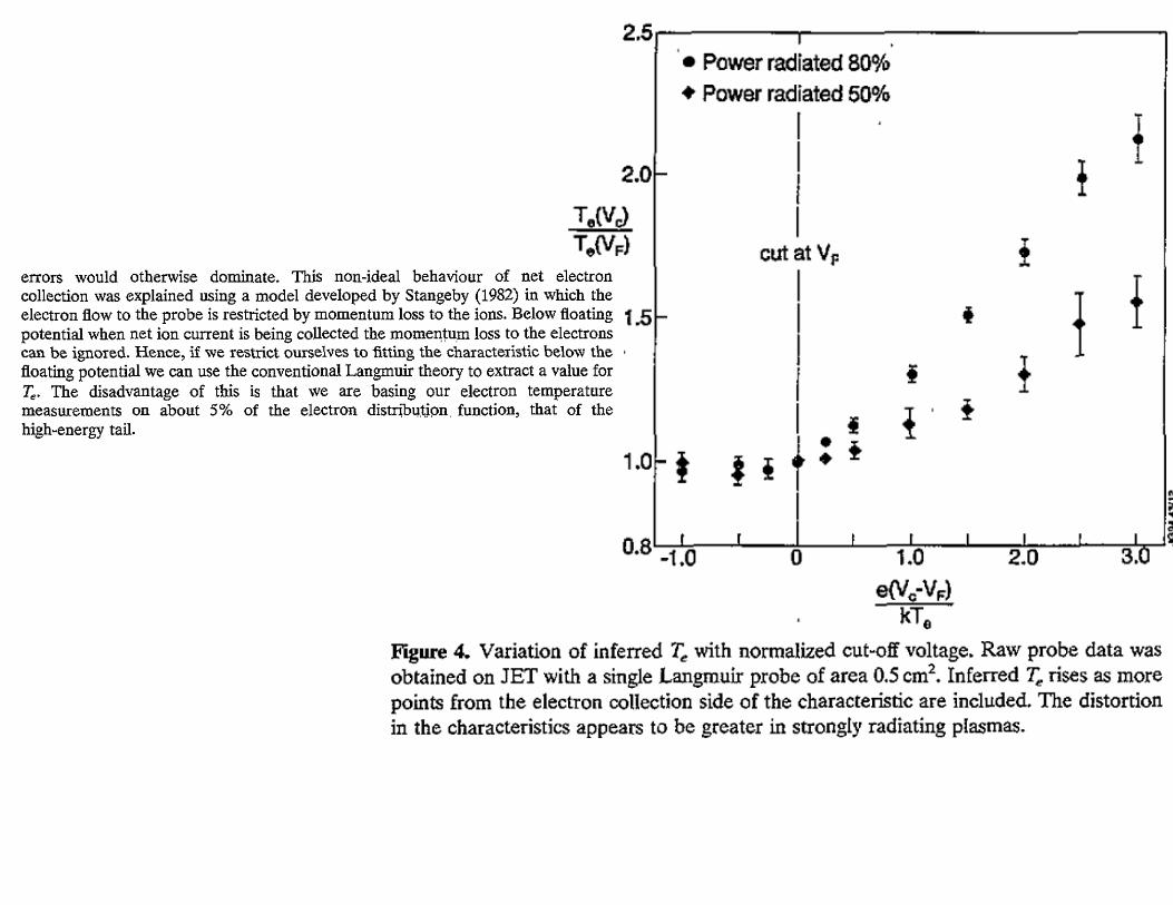


Next Lecture(Wednesday)
• Ch. 7 Problems
• Ch. 8: Instabilities