led-ldr based railway crack detection scheme basic rationale · pdf fileled-ldr based railway...
TRANSCRIPT

LED-LDR Based Railway Crack Detection Scheme
Basic rationale:
Transport is a key necessity for specialization that allows production and consumption of products to occur at different locations. Transport has throughout history been a spur to expansion as better transport leads to more trade. Economic prosperity has always been dependent on increasing the capacity and rationality of transport. But the infrastructure and operation of transport has a great impact on the land and is the largest drainer of energy, making transport sustainability and safety a major issue. In India, we find that rail transport occupies a prominent position in providing the necessary transport infrastructure to sustain and quench the ever-burgeoning needs of a rapidly growing economy. Today, India possesses the fourth largest railway network in the world. However, in terms of the reliability and safety parameters, we have not yet reached truly global standards. The principal problem has been the lack of cheap and efficient technology to detect problems in the rail tracks and of course, the lack of proper maintenance of rails which have resulted in the formation of cracks in the rails and other similar problems caused by anti-social elements which jeopardize the security of operation of rail transport. In the past, this problem has lead to a number of derailments resulting in a heavy loss of life and property. Cracks in rails have been identified to be the main cause of derailments in the past, yet there have been no cheap automated solutions available for testing purposes. Hence, owing to the crucial repercussions of this problem, we have worked on implementing an efficient and cost effective solution suitable for large scale application. We hope that our idea can be implemented in the long run to facilitate better safety standards and provide effective testing infrastructure for achieving better results in the future.
Statistics to justify the problem:
The Indian Railways, today has 113,617 kilometres (70,598 mi).of total track over a route of 63,974 kilometres (39,752 mi) and 7,083 stations.

It has the world's fourth largest railway network after those of the United States, Russia and China. The railways traverse the length and breadth of the country and carry over 30 million passengers and 2.8 million tons of freight daily. It is the world's second largest commercial or utility employer, with more than 1.36 million employees. Despite boasting such impressive figures, we find that Indian rail network is still on the growth trajectory trying to fuel the economic needs of our nation. Though we find rail transport in India growing at a rapid pace, the associated safety infrastructure facilities have not kept up with the aforementioned proliferation. Our facilities are poor when compared to the international standards and as a result, we have been having frequent derailments that have resulted in severe loss of valuable human lives and also property. To demonstrate the gravity of the problem, statistics say that there have been 11 accidents in 2011 till the month of july alone, which leaves much to be desired regarding rail safety. On further analysis of the factors that cause these rail accidents, recent statistics reveal that approximately 60% of all the rail accidents have derailments as their cause, of which about 90% is due to cracks on the rails either due to natural causes (like excessive expansion due to heat) or due to anti- social elements. These cracks and other problems with the rails generally go unnoticed due to improper maintenance and the currently irregular and manual track line monitoring that is being carried out in the current situation.
Survey of contemporary solutions:
The prompt detection of the conditions in rails that may lead to a crack or rather a break now plays a critical role in the maintenance of rails worldwide. The understanding of these mechanisms is constantly improving and the evolution of a range of complementary (Non Destructive Testing)NDT techniques has resulted in a number of tools for us to choose from. Among the inspection methods used to ensure rail integrity, the common ones are visual inspection, ultrasonic inspection and eddy current inspection. Ultrasonic Inspections are common place in the rail industry in many foreign countries. It is a relatively well understood technique and was thought to be the best solution to crack detection. However, Ultrasonics can

only inspect the core of materials; that is, the method cannot check for surface and near-surface cracking where many of the faults are located. Eddy currents are used to tide over this limitation associated with ultrasonics. They are effectively used to check for cracks located at the surface of metals such as rails. Further, (Magnetic Particle Inspection) MPI is also used in the rail industry but there are a number of problems inherent with this technique, some of which are mentioned below:
• Surface of the rail or component must first be cleaned of all coatings, rust and so on.
• To get a sensitive reading, contrast paint must first be applied to the rail, followed by the magnetic particle coating.
• The same inspection must then be carried out in two different directions at a very slow overall speed. However, in the Indian scenario, we find that the visual form of
inspection is widely used, though it produces the poorest results of all the methods. It is now becoming widely accepted that even surface cracking often cannot be seen by the naked eye.
Justification of the proposed solution: As mentioned in the literature survey, we find that the commonly
employed rail crack detection schemes in foreign countries are usually ultrasonic or eddy current based techniques which boast of reasonably good accuracy in most cases. However, the one characteristic which the above mentioned methods have in common is that they are both expensive, which makes them ineligible for implementation in the current Indian scenario. Also, ultrasonics can only inspect the core of materials; that is, the method cannot check for surface and near-surface cracking where many of the faults are located. In addition, ultrasonic inspection of rails is usually restricted to low speeds of around 20-30mph, which limits the viability of testing many tracks regularly. Many of the most serious defects that can develop in the rail head can be very difficult to detect using the currently available inspection equipment. Generally, one of the reasons for slow

inspection speeds using conventional NDT is the need for couplant between the transducer and the track using either liquid or dry couplant materials. The Laser solution that we considered initially, offered some advantages in terms of cost but altogether it was inefficient due to the high power needed to power the laser and also the limitations inherent to laser. The main problem was that as lasers generally have long wavelengths, they tend to cut through reflecting surfaces instead of getting reflected back which poses a serious problem in a rail crack detection system. Furthermore human eyes are sensitive to laser light and therefore in case of a problem with the operation, the exposure to harmful laser light poses a safety hazard. Thus after having weighed up all our options, we have chosen the cheaper means of a LED-LDR based detection which provides us with ruggedness and reasonably accurate crack detection.
Advantages of the proposed solution:
The currently existing technical solutions offered by many companies in the detection of cracks in rails involve periodic maintenance coupled with occasional monitoring usually once a month or in a similar timeframe. Our project however possesses the inherent advantage of facilitating monitoring of rail tracks on a daily basis during nights when the usual train traffic is suspended. Further, we believe that the simplicity of our idea and the easy-availability of the components make our project ideal for implementation on a large scale with very little initial investment. The simplicity of our project ensures robustness of operation and also the design has been carefully modified to permit rugged operation. Another disadvantage that can be attributed to the conventional commercially available testing equipments is that they are heavy which poses a practical limitation. However, this important disadvantage has been rectified in our project as the design is simple and sensible enabling the device to be easily portable. While designing the mechanical parts of the robot, due consideration has been given to the variable nature of the tracks and the unique challenges posed by the deviations in the Indian scenario. For example, in areas near road-crossings the outer part of the track is usually

covered with cement. Also, there is always the problem of rocks obstructing the path on the inside parts of the rails. The specialized wheels that have been provided in our robot have taken this into account and are specifically designed to overcome the aforementioned problem.
Mechanical design:

Technical overview:
The core of our proposed crack detection scheme basically consists of a Light Emitting Diode (LED)-Light Dependent Resistor (LDR) assembly

that functions as the rail crack detector. The principle involved in this crack detection is the concept of LDR. The LED will be attached to one side of the rails and the LDR to the opposite side. During normal operation, when there are no cracks, the LED light does not fall on the LDR and hence the LDR resistance is high. When the LED light falls on the LDR, the resistance of the LDR gets reduced and the amount of reduction will be approximately proportional to the intensity of the incident light. As a consequence, when light from the LED deviates from its path due to the presence of a crack or a break, a sudden decrease in the resistance value of the LDR can be observed. This change in resistance indicates the presence of a crack or some other similar structural defect in the rails. In order to detect the current location of the device in case of detection of a crack, we make use of a GPS receiver whose function is to receive the current latitude and longitude data. To communicate the received information, we make use of a GSM modem. The GSM module is being used to send the current latitude and longitude data to the relevant authority as an SMS. The aforementioned functionality has been achieved by interfacing the GSM and GPS modules with the ATMEGA328 microcontroller on-board the Arduino Uno board. The arduino integrated development environment is an open-source project which simplified the coding greatly. The robot has four wheels which are powered by two 12V batteries.
Block diagram:
ATMEGA328
(Arduino Uno) H BRIDGE
Power DC
Motors
LED
LDR
GSM module
GPS module

Explanation of the algorithm:
After the bot is powered on it executes the following algorithm:
1) The following steps are done to calibrate the Light Dependent Resistor (LDR). This step is necessary to compensate for the variation of ambient light.
a) Set LOWleft=0, LOWright=0, HIGHleft=0, HIGHright=0
b) Switch off the left LED.
c) Average the signal from the left LDR and store it in LOWleft. To do this read the signal from the left LDR and accumulate it in LOWleft, i.e. keep adding the signal from the left LDR to LOWleft. Then divide LOWleft by total number of times the signal from left LDR is read (in our case 10).
d) Switch off the right LED.
e) Average the signal from the right LDR and store it in LOWright.
f) Switch on the left LED.
g) Average the signal from the left LDR and store it in HIGHleft.
h) Switch on the right LED.
i) Average the signal from the right LDR and store it in HIGHright.
2) GSM is turned ON. For this the baud rate is set as 9600 bps and the required parameters are set.
3) Motors are turned ON.

4) The signal from the left and the right LDR is read.
5) The values of the left and the right LDR are mapped between 0 and 1000. To do this use the following two formulas:
INTENSITYleft=1000.0*(analogRead(LDRleft)-LOWleft)/(HIGHleft-LOWleft)
INTENSITYright=1000.0*(analogRead(LDRright)-LOWright)/(HIGHright-LOWright)
analogRead(LDRleft) and analogRead(LDRright) are the signal from the left and the right LDR. INTENSITYleft and INTENSITYright are the mapped values.
6) If INTENSITYleft<LowThreshold (200 for our case) and INTENSITYright<LowThreshold (200 for our case) then
a) Motors are powered on
7) If INTENSITYleft>HighThreshold (800 for our case) and INTENSITYright>HighThreshold (800 for our case) then
a) Motor is powered off.
b) The coordinate of the bot is found using the onboard GPS reciever.
c) This coordinate is then sent to a predefined mobile number using the onboard GSM shield.

8) Jump to step 4.
Our code:
#include<string.h>
#include<ctype.h>
#include <GSM_Shield.h>
#include<string.h>
char number[]="+919790721683";
char text[50];
char TEXT[25];
byte type_sms=SMS_UNREAD;
GSM gsm;
int byteGPS=-1;
char linea[300] = "";
char comandoGPR[7] = "$GPRMC";
int cont=0;
int bien=0;
int conta=0;
int indices[13];
int flag=1;
int f=0;
int logic=0;
double LOWleft=0;

double HIGHleft=0;
double LOWright=0;
double HIGHright=0;
double INTENSITYleft=0;
double INTENSITYright=0;
int LEDleft=8;
int LEDright=9;
int LDRleft=2;
int LDRright=0;
int MPIN1=7;
int MPIN2=10;
int MPIN3=11;
int BrightLED=3;
void setup()
Serial.begin(9600);
pinMode(MPIN1,OUTPUT);
pinMode(LEDleft,OUTPUT);
pinMode(LEDright,OUTPUT);
digitalWrite(MPIN1,LOW);
digitalWrite(LEDleft,LOW);
digitalWrite(LEDright,LOW);
for (int i=0;i<300;i++)

linea[i]=' ';
gsm.TurnOn(9600);
gsm.InitParam(PARAM_SET_1);
gsm.Echo(0);
delay(3000);
for (int k=1; k<=10; k++)
delay(500);
LOWleft+=analogRead(LDRleft);
LOWleft/=10.0;
delay(3000);
for (int k=1; k<=10; k++)
delay(500);
LOWright+=analogRead(LDRright);
LOWright/=10.0;
digitalWrite(LEDleft,HIGH);
delay(3000);
for (int k=1; k<=10; k++)
delay(500);

HIGHleft+=analogRead(LDRleft);
HIGHleft/=10.0;
digitalWrite(LEDright,HIGH);
delay(3000);
for (int k=1; k<=10; k++)
delay(500);
HIGHright+=analogRead(LDRright);
HIGHright/=10.0;
Serial.println(LOWleft);
Serial.println(LOWright);
Serial.println(HIGHleft);
Serial.println(HIGHright);
digitalWrite(BrightLED,HIGH);
delay(10000);
digitalWrite(BrightLED,LOW);
analogWrite(MPIN2,0);
analogWrite(MPIN3,255);
digitalWrite(MPIN1,HIGH);
void loop()

do
INTENSITYleft=1000.0*(analogRead(LDRleft)-LOWleft)/(HIGHleft-LOWleft);
INTENSITYright=1000.0*(analogRead(LDRright)-LOWright)/(HIGHright-LOWright);
if (INTENSITYleft<200 && INTENSITYright<200)
if (logic==1)
digitalWrite(MPIN1,HIGH);
flag=1;
digitalWrite(BrightLED,LOW);
if (f==1)
digitalWrite(MPIN1,HIGH);
logic=0;
f=0;
else
if (INTENSITYleft>800 || INTENSITYright>800)

digitalWrite(MPIN1,LOW);
logic=1;
f=0;
while (bien!=6 && flag==1)
conta=0;
for (int i=0;i<300;i++)
linea[i]=' ';
do
byteGPS=Serial.read();
if (byteGPS == -1)
delay(100);
else
linea[conta]=byteGPS;
conta++;
while (byteGPS!=13);

cont=0;
bien=0;
for (int i=1;i<7;i++)
if (linea[i]==comandoGPR[i-1])
bien++;
if (bien==6)
for (int i=0;i<300;i++)
if (linea[i]==',')
indices[cont]=i;
cont++;
if (linea[i]=='*')
indices[12]=i;
cont++;

strcpy(text,"Latitude: ");
int k=10;
for (int j=indices[2];j<(indices[3]-1);j++, k++)
text[k]=linea[j+1];
text[k]='\n';
text[k+1]='\0';
strcpy(TEXT,"Longitude: ");
for (int j=indices[4], k=11;j<(indices[5]-1);j++, k++)
TEXT[k]=linea[j+1];
strcat(text,TEXT);
Serial.println(text);
flag=0;
gsm.SendSMS(number,text);
cont=0;
bien=0;
else

f=1;
digitalWrite(MPIN1,LOW);
Our team's effort in implementation:
We proceeded with our idea of creating a rail based crack detection scheme using a LED-LDR assembly for detection because, after conducting an extensive review of the existing solutions, we found our idea to be simple but effective. We used an ATMEGA328 on-board on the Arduino Uno board and henceforth the open source arduino IDE was used to program our microcontroller. The arduino board was selected for ease of use-as it is basically a plug-in board with a built-in bootloader that greatly simplified the coding process. When we set about trying to find a wireless communication technique suitable to our task, we encountered a number of problems regarding the feasibility and ruggedness parameters. Our initial idea of using FM transmission did not materialize owing to the inherent complexity of the associated circuitry which we tried to avoid as it would seriously jeopardize our claims of mass production of the proposed testing device and its subsequent implementation. Second, for a brief period of time, we considered using Zigbee protocol. But, it was later rejected due to its short range of operation which limited its utility in the practical scenario. Therefore, after considering all the available options, we decided to go for implementation using a GSM modem that exploits the ubiquitous nature of mobiles in today’s India. The GSM module is utilized in our project to send data as an SMS to the relevant authority in case a crack or break is detected in the rail lines. The GPS receiver that we have used can detect the current location of the robot with an accuracy of 2-5 meters and

its output has been suitably converted into text format through code, so that it can then be transmitted to a remote mobile device by means of the on-board GSM modem.
Details on testing the product:
The test plan formulated involved initial testing in a simulated track to study the feasibility of crack detection. The arrangement utilized some wooden planks kept in the form of tracks and the robot was made to traverse it. We included a break manually and found that the device successfully detected that user-created crack and the current latitude and longitude values were received by the GPS receiver, converted into a suitable text format and then finally transmitted to a mobile phone by means of the GSM module. This process, carried out in MIT’s workshop helped ascertain that the basic functionality was successfully achieved. After this initial simulated trial, the robot was tested on an actual track by making it traverse a small distance (equal to the length of the platform of chrompet- chennai). However, as the rail tracks did not contain any cracks, we were not able to test the GSM and GPS modules on field. But the previously mentioned simulated trial validates the project. Thus, the field trials indicate a fairly good degree of accuracy and also the GSM and GPS modules worked properly by transmitting the current latitude and longitude data to a mobile phone on detecting our simulated crack.
Resources and bibliography:

Appendix:
Arduino Uno:

OVERVIEW:
The Arduino Uno is a microcontroller board based on the ATmega328 (datasheet). It has 14 digital input/output pins (of which 6 can be used as PWM outputs), 6 analog inputs, a 16 MHz crystal oscillator, a USB connection, a power jack, an ICSP header, and a reset button. It contains everything needed to support the microcontroller; simply connect it to a computer with a USB cable or power it with a AC-to-DC adapter or battery to get started.
The Uno differs from all preceding boards in that it does not use the FTDI USB-to-serial driver chip. Instead, it features the Atmega8U2 programmed as a USB-to-serial converter. Revision 2 of the Uno board has a resistor pulling the 8U2 HWB line to ground, making it easier to put into DFU mode.
SUMMARY: Microcontroller ATmega328 Operating Voltage 5V Input Voltage (recommended)
7-12V
Input Voltage (limits) 6-20V
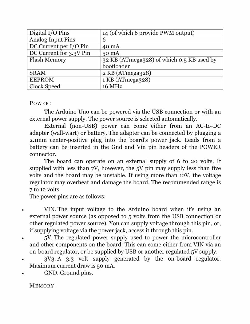
Digital I/O Pins 14 (of which 6 provide PWM output) Analog Input Pins 6 DC Current per I/O Pin 40 mA DC Current for 3.3V Pin 50 mA Flash Memory 32 KB (ATmega328) of which 0.5 KB used by
bootloader SRAM 2 KB (ATmega328) EEPROM 1 KB (ATmega328) Clock Speed 16 MHz
POWER:
The Arduino Uno can be powered via the USB connection or with an external power supply. The power source is selected automatically.
External (non-USB) power can come either from an AC-to-DC adapter (wall-wart) or battery. The adapter can be connected by plugging a 2.1mm center-positive plug into the board's power jack. Leads from a battery can be inserted in the Gnd and Vin pin headers of the POWER connector.
The board can operate on an external supply of 6 to 20 volts. If supplied with less than 7V, however, the 5V pin may supply less than five volts and the board may be unstable. If using more than 12V, the voltage regulator may overheat and damage the board. The recommended range is 7 to 12 volts. The power pins are as follows:
• VIN. The input voltage to the Arduino board when it's using an external power source (as opposed to 5 volts from the USB connection or other regulated power source). You can supply voltage through this pin, or, if supplying voltage via the power jack, access it through this pin.
• 5V. The regulated power supply used to power the microcontroller and other components on the board. This can come either from VIN via an on-board regulator, or be supplied by USB or another regulated 5V supply.
• 3V3. A 3.3 volt supply generated by the on-board regulator. Maximum current draw is 50 mA.
• GND. Ground pins.
MEMORY:

The ATmega328 has 32 KB (with 0.5 KB used for the bootloader). It also has 2 KB of SRAM and 1 KB of EEPROM (which can be read and written with the EEPROM library).
INPUT AND OUTPUT: Each of the 14 digital pins on the Uno can be used as an input or
output, using pinMode(), digitalWrite(), and digitalRead()functions. They operate at 5 volts. Each pin can provide or receive a maximum of 40 mA and has an internal pull-up resistor (disconnected by default) of 20-50 kOhms. In addition, some pins have specialized functions:
• Serial: 0 (RX) and 1 (TX). Used to receive (RX) and transmit (TX) TTL serial data. These pins are connected to the corresponding pins of the ATmega8U2 USB-to-TTL Serial chip.
• External Interrupts: 2 and 3. These pins can be configured to trigger an interrupt on a low value, a rising or falling edge, or a change in value. See the attachInterrupt() function for details.
• PWM: 3, 5, 6, 9, 10, and 11. Provide 8-bit PWM output with the analogWrite() function.
• SPI: 10 (SS), 11 (MOSI), 12 (MISO), 13 (SCK). These pins support SPI communication using the SPI library.
• LED: 13. There is a built-in LED connected to digital pin 13. When the pin is HIGH value, the LED is on, when the pin is LOW, it's off.
The Uno has 6 analog inputs, labeled A0 through A5, each of which provide 10 bits of resolution (i.e. 1024 different values). By default they measure from ground to 5 volts, though is it possible to change the upper end of their range using the AREF pin and the analogReference() function. Additionally, some pins have specialized functionality:
• TWI: A4 (SDA) and A5 (SCL). Support TWI communication using the Wire library.
There are a couple of other pins on the board:
• AREF. Reference voltage for the analog inputs. Used with analogReference().

• Reset. Bring this line LOW to reset the microcontroller. Typically used to add a reset button to shields which block the one on the board.
COMMUNICATION: The Arduino Uno has a number of facilities for communicating with a
computer, another Arduino, or other microcontrollers. The ATmega328 provides UART TTL (5V) serial communication, which is available on digital pins 0 (RX) and 1 (TX). An ATmega8U2 on the board channels this serial communication over USB and appears as a virtual com port to software on the computer. The '8U2 firmware uses the standard USB COM drivers, and no external driver is needed. However, on Windows, a .inf file is required. The Arduino software includes a serial monitor which allows simple textual data to be sent to and from the Arduino board. The RX and TX LEDs on the board will flash when data is being transmitted via the USB-to-serial chip and USB connection to the computer (but not for serial communication on pins 0 and 1).
A SoftwareSerial library allows for serial communication on any of the Uno's digital pins. The ATmega328 also supports I2C (TWI) and SPI communication. The Arduino software includes a Wire library to simplify use of the I2C bus; see the documentation for details. For SPI communication, use the SPI library.
PROGRAMMING The Arduino Uno can be programmed with the Arduino software
(download). Select "Arduino Uno from the Tools > Board menu (according to the microcontroller on your board). For details, see the reference and tutorials.
The ATmega328 on the Arduino Uno comes preburned with a bootloader that allows you to upload new code to it without the use of an external hardware programmer. It communicates using the original STK500 protocol (reference, C header files).
You can also bypass the bootloader and program the microcontroller through the ICSP (In-Circuit Serial Programming) header; see these instructions for details. The ATmega8U2 firmware source code is available . The ATmega8U2 is loaded with a DFU bootloader, which can be activated by connecting the solder jumper on the back of the board (near the map of Italy) and then
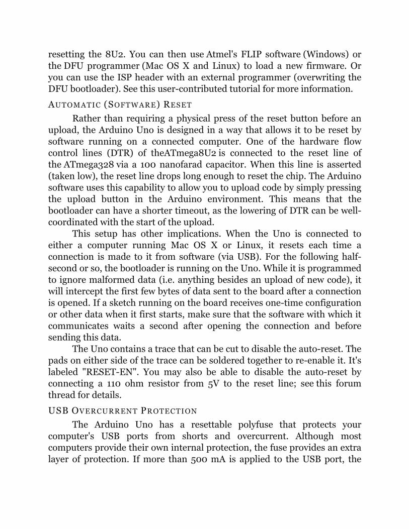
resetting the 8U2. You can then use Atmel's FLIP software (Windows) or the DFU programmer (Mac OS X and Linux) to load a new firmware. Or you can use the ISP header with an external programmer (overwriting the DFU bootloader). See this user-contributed tutorial for more information.
AUTOMATIC (SOFTWARE) RESET Rather than requiring a physical press of the reset button before an
upload, the Arduino Uno is designed in a way that allows it to be reset by software running on a connected computer. One of the hardware flow control lines (DTR) of theATmega8U2 is connected to the reset line of the ATmega328 via a 100 nanofarad capacitor. When this line is asserted (taken low), the reset line drops long enough to reset the chip. The Arduino software uses this capability to allow you to upload code by simply pressing the upload button in the Arduino environment. This means that the bootloader can have a shorter timeout, as the lowering of DTR can be well-coordinated with the start of the upload.
This setup has other implications. When the Uno is connected to either a computer running Mac OS X or Linux, it resets each time a connection is made to it from software (via USB). For the following half-second or so, the bootloader is running on the Uno. While it is programmed to ignore malformed data (i.e. anything besides an upload of new code), it will intercept the first few bytes of data sent to the board after a connection is opened. If a sketch running on the board receives one-time configuration or other data when it first starts, make sure that the software with which it communicates waits a second after opening the connection and before sending this data.
The Uno contains a trace that can be cut to disable the auto-reset. The pads on either side of the trace can be soldered together to re-enable it. It's labeled "RESET-EN". You may also be able to disable the auto-reset by connecting a 110 ohm resistor from 5V to the reset line; see this forum thread for details.
USB OVERCURRENT PROTECTION The Arduino Uno has a resettable polyfuse that protects your
computer's USB ports from shorts and overcurrent. Although most computers provide their own internal protection, the fuse provides an extra layer of protection. If more than 500 mA is applied to the USB port, the

fuse will automatically break the connection until the short or overload is removed.
PHYSICAL CHARACTERISTICS The maximum length and width of the Uno PCB are 2.7 and 2.1
inches respectively, with the USB connector and power jack extending beyond the former dimension. Four screw holes allow the board to be attached to a surface or case. Note that the distance between digital pins 7 and 8 is 160 mil (0.16"), not an even multiple of the 100 mil spacing of the other pins.
From Arduino to a Microcontroller on a Breadboard
Burning the Bootloader
If you have a new ATmega328 (or ATmega168), you'll need to burn the bootloader onto it. You can do this using an Arduino board as an in-system program (ISP). If the microcontroller already has the bootloader on it (e.g. because you took it out of an Arduino board or ordered an already-bootloaded ATmega), you can skip this section.
To burn the bootloader, follow these steps:
1. Upload the ArduinoISP sketch onto your Arduino board. (You'll need to select the board and serial port from the Tools menu that correspond to your board.)
2. Wire up the Arduino board and microcontroller as shown in the diagram to the right.
3. Select "Arduino Duemilanove or Nano
Using an Arduino board to burn the bootloader onto an ATmega on a breadboard.

w/ ATmega328" from the Tools > Board menu. (Or "ATmega328 on a breadboard (8MHz internal clock)" if using the minimal configuration described below.)
4. Run Tools > Burn Bootloader > w/ Arduino as ISP.
You should only need to burn the bootloader once. After you've done so, you can remove the jumper wires connected to pins 10, 11, 12, and 13 of the Arduino board.
Uploading Using an Arduino Board
Once your ATmega328p has the Arduino bootloader on it, you can upload programs to it using the USB-to-serial convertor (FTDI chip) on an Arduino board. To do, you remove the microcontroller from the Arduino board so the FTDI chip can talk to the microcontroller on the breadboard instead. The diagram at right shows how to connect the RX and TX lines from the Arduino board to the ATmega on the breadboard. To program the microcontroller, select "Arduino Duemilanove or Nano w/ ATmega328" from the the Tools > Board menu (or "ATmega328 on a breadboard (8 MHzinternal clock)" if you're using the minimal configuration described below). Then upload as usual.
Uploading sketches to an ATmega on a breadboard. Remember to remove the microcontroller from the Arduino board!

Minimal Circuit (Eliminating the External Clock)
If you don't have the extra 16 MHz crystal and 18-22 picofarad capacitors used in the above examples, you can configure the ATmega328 to use its internal 8 MHz RC oscillator as a clock source instead. (You don't really need the 10K pullup resistor on the reset pin either, so we remove it to get a truly minimal configuration.)
You'll need to install support for an additional hardware configuration:
1. Download this hardware configuration archive: breadboard.zip
2. Create a "hardware" sub-folder in your Arduino sketchbook folder (whose location you can find in the Arduino preferences dialog). If you've previously installed support for additional hardware configuration, you may already have a "hardware" folder in your sketchbook.
3. Move the "breadboard" folder from the zip archive to the "hardware" sub-folder of your Arduino sketchbook.
4. Restart the Arduino software.
5. You should see "ATmega328 on a breadboard (8 MHz internal clock)" in the Tools > Board menu.
Once you've done this, you can burn the bootloader and upload programs onto your ATmega328 as described above. Be sure to select "ATmega328 on a breadboard (8 MHz internal clock)" when burning the bootloader. (If you select the wrong item and configure the microcontroller to use an external clock, it won't work unless you connect one.)

Using an Arduino board to burn the bootloader onto an ATmegaon a breadboard (w/o an external clock).
Uploading sketches to an ATmega on a breadboard.
Getting Rid of the Arduino Board
Once you've programmed the ATmega on the breadboard, you can eliminate the Arduino. To do so, you'll need to provide an alternative power supply for the microcontroller.

Light Emitting Diode:
A light-emitting diode (LED) is a semiconductor light source. LEDs are used as indicator lamps in many devices and are increasingly used for other lighting. Introduced as a practical electronic component in 1962, early LEDs emitted low-intensity red light, but modern versions are available across the visible, ultraviolet and infrared wavelengths, with very high brightness.
When a light-emitting diode is forward biased (switched on), electrons are able to recombine with electron holes within the device, releasing energy in the form of photons. This effect is called electroluminescence and the color of the light (corresponding to the energy of the photon) is determined by the energy gap of the semiconductor. LEDs are often small in area (less than 1 mm2), and integrated optical components may be used to shape its radiation pattern. LEDs present many advantages over incandescent light sources including lower energy consumption, longer lifetime, improved robustness, smaller size, faster switching, and greater durability and reliability. LEDs

powerful enough for room lighting are relatively expensive and require more precise current andheat management than compact fluorescent lamp sources of comparable output.
Light-emitting diodes are used in applications as diverse as replacements for aviation lighting, automotive lighting (particularly brake lamps, turn signals and indicators) as well as in traffic signals. The advantages of LEDs mentioned above have allowed new text and video displays and sensors to be developed, while their high switching rates are also useful in advanced communications technology. Infrared LEDs are also used in the remote control units of many commercial products including televisions, DVD players, and other domestic appliances.
Motors:
To control the motor we need a motor driver as the current drawn by the motor is large to be provided from the micro-controller. Thus a motor driver IC L298N is mounted on the shield. This IC can control two motors. An H- Bridge setup is needed to provide the sufficient power to the motor. The driver controls the motors through this H- Bridge. The motors could be connected to the shield through the screw terminals which are named as MOTOR A and MOTOR B. The screw terminals in between these two motors are the dedicated power source to the motor. The MOTOR A is connected to Pin 6 and 5. The MOTOR B is connected to 10 and 11.
H- Bridge
The term H bridge is derived from the typical graphical representation of such a circuit. An H bridge is built with four switches (solid-state or mechanical). When the switches S1 and S4 (according to the first figure) are closed (and S2 and S3 are open) a positive voltage will be

applied across the motor. By opening S1 and S4 switches and closing S2 and S3 switches, this voltage is reversed, allowing reverse operation of the motor.
Using the nomenclature above, the switches S1 and S2 should never be closed at the same time, as this would cause a short circuit on the input voltage source. The same applies to the switches S3 and S4. This condition is known as shoot-through.
IC L298N
The L298N ia a high-voltage, high-current dual full-bridge driver designed to accept TTL logic levels such as those from a PIC, BASIC Stamp, or similar microcontroller and drive inductive loads like motors (DC and stepper), relays, and solenoids. Also features current sensing outputs for each half of the bridge to detect current draw. Features Include :
• Oprating Voltages up to 46 V
• Total DC current up to 4 A
• Overtemperature Protection
• High noise immunity
• Large heatsink tab
Pin Outs :

Connection of the IC to the motors through the H- Brigde:
The connections are made through the following diagram:
Atmega328:
Features
• High Performance, Low Power Atmel®AVR® 8-Bit Microcontroller
• Advanced RISC Architecture
– 131 Powerful Instructions – Most Single Clock Cycle Execution
– 32 x 8 General Purpose Working Registers
– Fully Static Operation

– Up to 20 MIPS Throughput at 20MHz
– On-chip 2-cycle Multiplier
• High Endurance Non-volatile Memory Segments
– 4/8/16/32KBytes of In-System Self-Programmable Flash program memory
– 256/512/512/1KBytes EEPROM
– 512/1K/1K/2KBytes Internal SRAM
– Write/Erase Cycles: 10,000 Flash/100,000 EEPROM
– Data retention: 20 years at 85°C/100 years at 25°C(1)
– Optional Boot Code Section with Independent Lock Bits
• In-System Programming by On-chip Boot Program
• True Read-While-Write Operation
– Programming Lock for Software Security
• Atmel® QTouch® library support
– Capacitive touch buttons, sliders and wheels
– QTouch and QMatrix® acquisition
– Up to 64 sense channels
• Peripheral Features
– Two 8-bit Timer/Counters with Separate Prescaler and Compare Mode
– One 16-bit Timer/Counter with Separate Prescaler, Compare Mode, and Capture
Mode
– Real Time Counter with Separate Oscillator
– Six PWM Channels

– 8-channel 10-bit ADC in TQFP and QFN/MLF package
Temperature Measurement
– 6-channel 10-bit ADC in PDIP Package
Temperature Measurement
– Programmable Serial USART
– Master/Slave SPI Serial Interface
– Byte-oriented 2-wire Serial Interface (Philips I2C compatible)
– Programmable Watchdog Timer with Separate On-chip Oscillator
– On-chip Analog Comparator
– Interrupt and Wake-up on Pin Change
• Special Microcontroller Features
– Power-on Reset and Programmable Brown-out Detection
– Internal Calibrated Oscillator
– External and Internal Interrupt Sources
– Six Sleep Modes: Idle, ADC Noise Reduction, Power-save, Power-down, Standby,
and Extended Standby
• I/O and Packages
– 23 Programmable I/O Lines
– 28-pin PDIP, 32-lead TQFP, 28-pad QFN/MLF and 32-pad QFN/MLF
• Operating Voltage:
– 1.8 - 5.5V
• Temperature Range:
– -40°C to 85°C

• Speed Grade:
– 0 - [email protected] - 5.5V, 0 - [email protected] - 5.5.V, 0 - 20MHz @ 4.5 - 5.5V
• Power Consumption at 1MHz, 1.8V, 25°C
– Active Mode: 0.2mA
– Power-down Mode: 0.1ìA
– Power-save Mode: 0.75ìA (Including 32kHz RTC)
LDR (Light Dependent Resistor):
The LDR is a light dependent resistor ie. the resistance of the LDR is inversely proportional to the intensity of light incident on it. It is provided on board to interface the board with the real world luminous intensity as the parameter. It is connected in the lower half of a potential divider configuration with a 10K ohm resistor, so that the resistor-ldr junction voltage is inversely proportional to the amount of light incident on it. This potential divider is connected on analog pin 3. The corresponding jumper is on the right side of the LDR.
GSM Module:

GSM Playground - GSM Shield for Arduino
Description:
GSM Playground is a GSM Shield designed for Arduino based boards (Arduino Duemilanove, Arduino MEGA, Seeeduino Mega...). It is built on a well known and reliable GSM/GPRS Module GE-863 QUAD from Telit. This Module is pretty small so it is placed directly on the Shield printed circuit board. The GSM Playground offers next to the GSM capabilities lots of other features like recognizing of DTMF signal, measuring of ambient temperature and others. It will show you the way how there is possible to use GSM network in your application built on the great Arduino board.
The GSM Playground can be used for:
• Security devices - listening of protected area, scanning of sensors, controlling of door lock or klaxon, measurement of ambient temperature, remote controlling of other devices using SMS or DTMF signal, remote shouting at a burglar using embedded amplifier.
• Domestic automation - remote opening of doors or gates using DTMF or just a call, switching of lights or sauna, controlling of heating, handsfree voice communication with somebody at home, emergency

controlling of a house water inlet, full duplex baby sitter device working around the world.
• General M2M applications - the GSM Playground can be used also for wireless GSM/GPRS Machine to Machine application or M2A (Machine to Arduino) communication.
Features:
Embedded GSM/GPRS Module GE-863 QUAD features a Quad-Band GPRS Class 10 (GSM 850, 900, DCS 1800, PCS1900 MHz) as well as extended temperature range and RF Sensitivity. It is soldered directly on the bottom side of the Shield PCB using the through hole technique. This method is more reliable for development boards and allows accessing of all module signals. The module is equipped with the chipset V3 (firmware 6.04.104).
Power supply for GSM Module is able to handle high ripple current (2A) when the GSM Module is active. It is designed with Micrel MIC29302. The Shield is powered from an Arduino board so it can be powered either directly from USB or from an adaptor through Arduino board. The setting of supply path is automatic. A large capacitor is used for voltage filtration so that you can easily supply the board directly from USB (guaranteed for calls and CSD data). We recommend to use an AC-DC adaptor or LiPol battery for GPRS connection.
Connector for 3,7V LiPol battery and Charging circuit – it is possible to connect 3,7V LiPol battery so that it can be used for supplying power to the

GSM Module and also to the Arduino board. The battery is charged during normal operation of the GSM Shield from USB or adaptor with a current of 200mA. Battery operation can be selected from a switch. This feature is also helpful if the computer is not able to deliver the current required by the GSM module (during class 10 GPRS connection). It is recommended to use 3,7V LiPol battery with capacity from 500mAh to 1000mAh with a JST connector. An appropriate battery is 1000mAh LiPol battery or 860mAh LiPol battery.
Electret Microphone – the mike feature is based on a sensitive electret microphone that offers together with other circuits and particular PCB layout the clear sound. Even the GSM noise is quite aggressive but there is no typical GSM noise in the microphone path at all.
800mW Fully-Differential Audio Amplifier with connector – the Shield has a connector for loudspeaker 8Ω so you can use it together with embedded microphone as a handsfree phone. The chosen power amplifier (TPA6203A1) is especially suitable for noisy GSM environment so the sound is completely clear and free of any typical tdn-tdn-tdn :-). We provide suitable Loudspeaker or Mini Loudspeaker - both are equipped by appropriate connector.
Embedded DTMF Receiver – this feature allows controlling of any other function of GSM Playground using of an ordinary phone. DTMF circuit (based on Holtek HT9170) is able to recognize up to 16 different signals (buttons on your mobile phone) and transfer this information to Arduino board for other evaluation. It is possible to control just a relay but also increase a volume of loudspeaker or mute the microphone using this feature.
Electrodynamic Buzzer – embedded buzzer (85dB) can be used as a simple ringer if the loudspeaker is not used. It is possible to choose from up to 32 ring tones that are stored in the GSM Module.
ON/OFF Button – there is a button for turning ON and OFF of the module. It is possible to do the same directly from the Arduino board. The reset

signal of the GSM module is connected to the Arduino. This feature can help to improve a reliability of the whole application.
Enhanced serial communication – this feature can help you to develop your Arduino application faster and better. There is a switch for controlling of the way of serial communication. In the first position you can communicate from PC terminal software directly to the GSM Module. This is very useful for trying and learning of the GSM Module AT commands. The second position switches to communication between Arduino - PC and Arduino - GSM Module. In this position the Arduino board can communicate with PC application as we are used to but also with the GSM module.
Back up capacitor for time and alarm features – the adjustment of time can be quite annoying so there is a back up capacitor 0,22F on the PCB. It is able to backup Real Time Clock embedded in the GSM Module for minimally 24 hours. The GSM Module offers also Alarm related functions – Alarm signal can wake up an Arduino board in desired time by a reset, then the board can do something (send SMS) and go sleep again...
Temperature Sensor – built in temperature sensor LM61BIM3 allows measuring of the temperature from −25°C to +85°C with accuracy ±2.0°C at 25°C. The LM61's output voltage is linearly proportional to Celsius (Centigrade) temperature (+10 mV/°C) and it makes it very easy to use.
User Button and User LED – this simple user interface can be used for different purpose (e.g. make a call, send a SMS, indicate a call...).
User Connector – this connector offers 4 digital inputs or outputs and several supplying voltages so it can be easily used to make your application more versatile.
Standard SMA Connector for GSM antenna – there is a right angle SMA female connector soldered on the PCB so the connection of antenna can be very simple. This Quad-band Antenna is suitable because it is pretty small.

Embedded SIM card holder – the quality SIM card holder equipped with the contact for safe removing of SIM card is soldered directly on the Shield PCB.
Stackable feature – GSM Playground accepts prototype shields or other boards with Arduino compatible interface. The GSM Shield uses digital pins 0 to 9 but the pins 6,7,8 and 9 can be also used for other purpose (they can be switched to high impedance). The GSM Playground is compatible with Arduino Ethernet Shield.
PCB Layout is made with a special care of well grounding and noises elimination even though it is still only cheap two layer PCB.
Creative Commons Attribution – the whole project is released under Share Alike 3.0 License
Dimensions: 53,5 x 74 mm
Initial setup AT commands: We start working with AT commands to setup and check the status of the GSM modem.

AT Returns a "OK" to confirm that modem is working AT+CPIN="xxxx" To enter the PIN for your SIM ( if enabled ) AT+CREG? A "0,1" reply confirms your modem is connected to
GSM network AT+CSQ Indicates the signal strength, 31.99 is maximum. we should try sending a few SMS using the Control Tool above to make sure your GSM modem can send SMS before proceeding.
AT commands:
AT+CMGF=1 To format SMS as a TEXT message AT+CSCA="+xxxxx" Set your SMS center's number. Check with your
provider.
To send a SMS, the AT command to use is AT+CMGS AT+CMGS="+yyyyy" <Enter> > Your SMS text message here <Ctrl-Z> The "+yyyyy" is your recipient's mobile number. Receiving SMS using AT commands
The GSM modem can be configured to response in different ways when it receives a SMS.
a) Immediate - when a SMS is received, the SMS's details are immediately sent to the host computer (DTE) via the +CMT command
AT+CMGF=1 To format SMS as a TEXT message AT+CNMI=1,2,0,0,0 Set how the modem will response when a SMS is
received
When a new SMS is received by the GSM modem, the DTE will receive the following :

+CMT : "+61xxxxxxxx" , , "04/08/30,23:20:00+40" This the text SMS message sent to the modem The computer (DTE) will have to continuously monitor the COM serial port, read and parse the message.
b) Notification - when a SMS is received, the host computer ( DTE ) will be notified of the new message. The computer will then have to read the message from the indicated memory location and clear the memory location.
AT+CMGF=1 To format SMS as a TEXT message AT+CNMI=1,1,0,0,0 Set how the modem will response when a SMS is
received
When a new SMS is received by the GSM modem, the DTE will receive the following ...
+CMTI: "SM",3 Notification sent to the computer. Location 3 in SIM memory
AT+CMGR=3 <Enter>
AT command to send read the received SMS from modem
The modem will then send to the computer details of the received SMS from the specified memory location ( eg. 3 ) .. +CMGR: "REC READ","+61xxxxxx",,"04/08/28,22:26:29+40" This is the new SMS received by the GSM modem After reading and parsing the new SMS message, the computer (DTE) should send a AT command to clear the memory location in the GSM modem .. AT+CMGD=3 <Enter> to clear the SMS receive memory location in the GSM modem

if the computer tries to read an empty/cleared memory location, a +CMS ERROR: 321 will be sent to the computer.
Connecting a Parallax GPS module to the Arduino
(Adapted from Igor Gonzlez Martn's Spanish language tutorial here.)
This tutorial shows how to connect a Parallax GPS module to the Arduino, and how to use Arduino code to read information like date, time, location and satellites in view from the standard NMEA data streams that the module produces.
Hardware Connections:
The module connects to the Arduino through a 4800 bps TTL-level interface (8 data bits, no parity, 1 stop bit, non-inverted). Only four wires are needed to read the module's GPS data.

Understanding NMEA GPS strings
GPS modules typically put out a series of standard strings of information, under something called the National Marine Electronics Association (NMEA) protocol.
The tutorial code at the bottom of this page demonstrates how to decode and display the most common string, called $GPRMC. If all you need is date, time and position, you can to skip reading this, and just run the code below.
While you can write software to serially request other strings from the Parallax module, the following strings are automatically transmitted when the "/RAW" pin is pulled low.
• $GPGGA: Global Positioning System Fix Data
• $GPGSV: GPS satellites in view
• $GPGSA: GPS DOP and active satellites
• $GPRMC: Recommended minimum specific GPS/Transit data

Each of these sentences contains a wealth of data. For example, here are a few instances of the $GPRMC string, aka the "Recommended minimum specific GPS/Transit data" string:
Eg1. $GPRMC,081836,A,3751.65,S,14507.36,E,000.0,360.0,130998,011.3,E*62
Eg2. $GPRMC,225446,A,4916.45,N,12311.12,W,000.5,054.7,191194,020.3,E*68
225446 Time of fix 22:54:46 UTC A Navigation receiver warning A = Valid
position, V = Warning 4916.45,N Latitude 49 deg. 16.45 min. North 12311.12,W Longitude 123 deg. 11.12 min. West
000.5 Speed over ground, Knots 054.7 Course Made Good, degrees true
191194 UTC Date of fix, 19 November 1994 020.3,E Magnetic variation, 20.3 deg. East
*68 mandatory checksum
Eg3: $GPRMC,220516,A,5133.82,N,00042.24,W,173.8,231.8,130694,004.2,W*70
1 2 3 4 5 6 7 8 9 10 11 12
1 220516 Time Stamp
2 A validity - A-ok, V-invalid
3 5133.82 current Latitude
4 N North/South
5 00042.24 current Longitude
6 W East/West
7 173.8 Speed in knots

8 231.8 True course
9 130694 Date Stamp
10 004.2 Variation
11 W East/West
12 *70 checksum
eg4. for NMEA 0183 version 3.00 active the Mode indicator field is added
$GPRMC,hhmmss.ss,A,llll.ll,a,yyyyy.yy,a,x.x,x.x,ddmmyy,x.x,a,m*hh
Field #
1 UTC time of fix 2 Data status (A=Valid position, V=navigation receiver
warning) 3 Latitude of fix 4 N or S of longitude 5 Longitude of fix 6 E or W of longitude 7 Speed over ground in knots 8 Track made good in degrees True
9
UTC date of fix
10
Magnetic variation degrees (Easterly var. subtracts from true course)
11
E or W of magnetic variation
12
Mode indicator, (A=Autonomous, D=Differential, E=Estimated, N=Data not valid)
13 Checksum