legend specification guide - window tech · specification guide effective from march 2009 technical...
TRANSCRIPT

Specification GuideEffective from March 2009
Technical Data
Accreditations
Schematics
FAQs

Synseal is a systems company with a difference. It has been
involved at all levels in the PVC-U window industry. It started in
1980 and within 18 months of opening the first shop, Synseal
had opened 13 showrooms across the East Midlands. Later
Synseal added a fabrication facility and by 1987 1,000 frames
were being fabricated a week with a nationwide customer base.
In 1991 Synseal started extruding profile.
The success of the fabrication business meant Synseal was in
direct competition with some customers. That’s why it pulled out
of the domestic market in 1991. And why it pulled out of
fabricating in 1995. At that time Synseal was fabricating 2,200
frames a week. This business was sold to JBS Industries – and is
still a strong business today.
Today Synseal is number one in windows and conservatories, an
achievement no other company has attained. More fabricators
choose Synseal than any other company. So it’s hardly surprising
that one-in-ten windows and one-in-four conservatory roofs are
made with Synseal products.
This guide contains details of the accreditations, frequently
asked questions, schematics and technical data for Legend
PVC-U window and door system. The system was launched in
2000 by Permacell Finesse Ltd, subsequently bought by Synseal
in 2005.
About
*Source: Windowbase Database
All information in this manual is provided for guidance only.
Synseal Extrusions Ltd cannot be held responsible for the way inwhich the information in this manual is interpreted.
We reserve the right to alter specifications and descriptionswithout prior notice as part of our policy of continual development.
All dimensions are in millimetres. Do not scale drawings.
3
4
Contents
AccreditationsAccreditations
5
FAQsFAQs
Internally Beaded Casement Window and Externally Beaded Casement Window
Sculptured Internally Beaded Casement Window and Tilt & Turn Window
Double Door and Composite Door
Residential Door and Patio Horizontal Cross Section
70mm Coupling Details & Sizes - 5RA-LCM1, 5RA-MCM1, 5RA-HDC1 and 5RA-HDC2
6-78-9
10-1112-1314-15
SchematicsSchematics
Main Technical Details
Available Profile Colours
Thermal Expansion of PVC-U and Exposure Categories
‘U’ - Values and Energy Ratings
Safe Working Capacities of Bay-Poles & Posts
PVC-U Windows in Fires
Frame Limits for Coupling Mullions
Size Limits for Coupling Mullions (including H/Duty Coupling Mullions)
Sound Transmission Through Windows
16171819
20-212223
24-2526-27
Technical DataTechnical Data
Details of the accreditations that Synseal Extrusions Ltd hold from recognised authorities
Frequently Asked Questions relating to technical aspects, quality assurance and window/door/patio installation
Cross section drawings of Legend windows and doors
Technical data relating to various aspects of Legend windows and doors
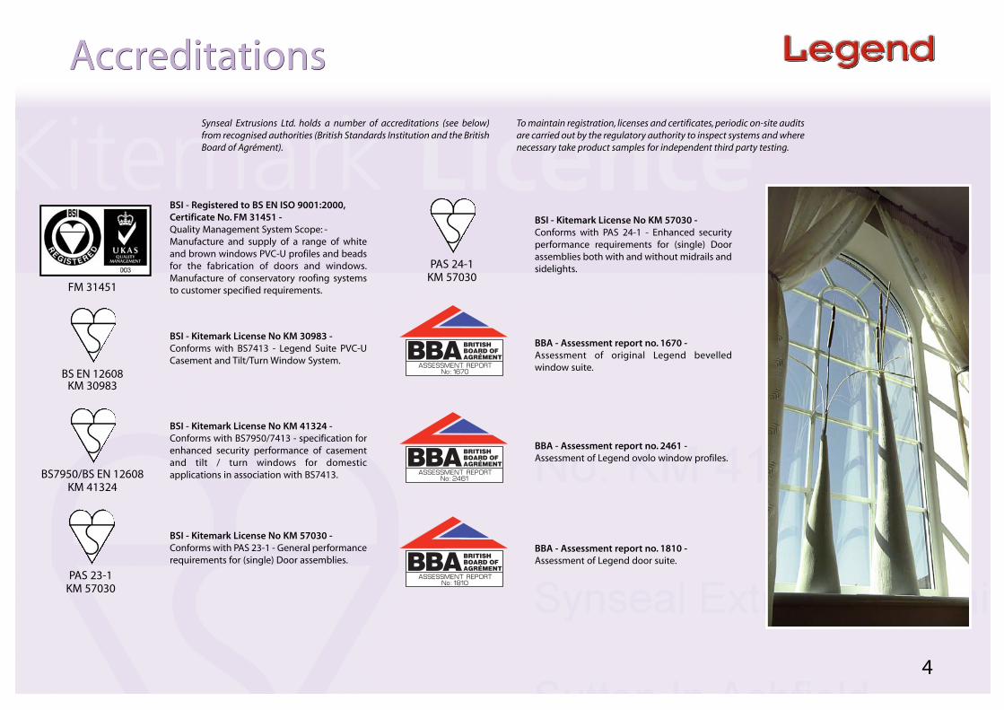
BSI - Kitemark License No KM 57030 -Conforms with PAS 24-1 - Enhanced securityperformance requirements for (single) Doorassemblies both with and without midrails andsidelights.
BBA - Assessment report no. 1670 -Assessment of original Legend bevelledwindow suite.
BBA - Assessment report no. 2461 -Assessment of Legend ovolo window profiles.
BBA - Assessment report no. 1810 -Assessment of Legend door suite.
FM 31451
4
BS EN 12608KM 30983
BS7950/BS EN 12608KM 41324
AccreditationsAccreditations
BSI - Registered to BS EN ISO 9001:2000,Certificate No. FM 31451 -Quality Management System Scope: -Manufacture and supply of a range of whiteand brown windows PVC-U profiles and beadsfor the fabrication of doors and windows.Manufacture of conservatory roofing systemsto customer specified requirements.
BSI - Kitemark License No KM 30983 -Conforms with BS7413 - Legend Suite PVC-UCasement and Tilt/Turn Window System.
BSI - Kitemark License No KM 41324 -Conforms with BS7950/7413 - specification forenhanced security performance of casementand tilt / turn windows for domesticapplications in association with BS7413.
BSI - Kitemark License No KM 57030 -Conforms with PAS 23-1 - General performancerequirements for (single) Door assemblies.
PAS 23-1KM 57030
PAS 24-1KM 57030
Synseal Extrusions Ltd. holds a number of accreditations (see below)from recognised authorities (British Standards Institution and the BritishBoard of Agrément).
To maintain registration, licenses and certificates, periodic on-site auditsare carried out by the regulatory authority to inspect systems and wherenecessary take product samples for independent third party testing.

5
What are the maximum sizes for your windows?For Kitemarked windows, the following maximum sizes apply:
Top hung at 1200Pa:Max size = 1000mm x 1000mm (unreinforced)
= 1100mm x 1100mm (reinforced using aluminium)= 1200mm x 1200mm (reinforced using steel)
Side hung at 1200Pa:Max size = 700mm x 1000mm (unreinforced)
= 700mm x 1200mm (reinforced using aluminium)= 850mm x 1500mm (reinforced using steel)
What woodgrain finish do you use and do you offer other colours?We offer Light Oak, Mahogany and Cherrywood finishes (these areavailable internally/externally and also on white). The colours we offer areAnthracite Grey, Black Brown, Dark Red (Burgundy), Steel Blue (Oxford)and Dark Green (Brookland). Please contact the sales office for information.
What colour are Synseal’s extruded products?If matching door panels, the colour code nearest match for white profileis C152. If difficulty is experienced it is advisable to send a sample ofprofile to the door panel supplier.
What is the standard stack height for friction stays on Synseal Legendcasement windows?17mm is the standard, although 15.5mm is ideal.
What back-set espag or shootbolt will fit into Synseal casement?A 22mm back-set espag or shootbolt will be fine.
Which back-set door lock is recommended?35mm is recommended.
What exposure ratings do your windows achieve?Up to 2400 pascals is achievable.
Do you offer the service of Patio Midrail End milling and how do Imeasure for Midrail length? Yes, and we require the overall finished patio width (inc. number of panes).
For woodgrain on white windows how do I know which face to order?
The price lists clearly identify which faces are foiled by using A and B codes.
Can we use kitemark logo on our adverts?
No, use the phrase ‘Our Windows & Doors are manufactured from profile
supplied by Synseal Extrusions Ltd, which are Kitemarked to BS7413
(Licence no. KM30983), BS7950/7413 (Licence no. KM41324) and
PAS 23-1/BS7413 (Licence no. KM57030)’.
Does the profile have a BBA certificate?
No, but Synseal Legend profiles have been assessed by the BBA,
Assessment report no. 1670, no. 2461 and no. 1810.
Can I make a half hour fire rated door from Synseal Extrusions?
No, as with all PVC-U profile, Synseal Extrusions achieve a class 1 surface
spread of flame when tested to BS476 part 7.
Are PVC-U windows & doors load bearing?
No, but load bearing data is available for bay poles 5RA-BP2/5RA-CP901
(which are to be used in conjunction with Legend bay pole jack 5BPJL-RD
and square corner jack 5BPJL-SQ).
Is there any regrind material in Legend window and door profiles?
All Legend window and door profiles are extruded from 100% virgin
compound and are not diluted with second or more generation of
reground extrusion profile.
Is it necessary to install Safety Glass in patio doors?
Yes, the use of safety glass in buildings is specified in a British Standard -
refer to BS6262-4:1994. For further information, reference should also be
made to Building Regulations Approved Document N - Glazing.
When replacing windows do Tricklevents need to be installed?
Yes, as of early 2006. Refer to Building Regulations Approved Document F -
Ventilation.
Do I have to employ the services of a FENSA approved fitter when
installing windows and doors?
No, but if non-FENSA approved fitters are used, then application to the
local Building Control Office must be made to arrange appropriate
inspection and approval. However, it is recommended that FENSA
approved fitters are used.
Is it essential to have gas fires reserviced after fitting windows and doors?
No, but whilst it is not essential, this is always a good idea to ensure
ventilation is still adequate.
When replacing timber windows and/or doors with PVC-U ones, do I
need to check/replace as necessary the lintel above the removed
windows/doors to maintain structural integrity?
Yes, PVC-U windows are not designed to be load-bearing.
What is the minimum size for a fire escape window?The minimum size is an unobstructed openable area that is at least
0.33m2 (minimum dimensions: 750mm high and 450mm wide or 450mm
high and 750mm wide). The bottom of the openable area should not be
more than 1100mm from the floor. See Building Regulations Approved
Document B.
FAQsFAQs
Technical Quality Assurance Window/Door/PatioInstallationTechnical Quality Assurance Window/Door/PatioInstallation
Legend compound

5F1 - 34mm OUTER FRAME
5RS-FT1L - STEEL FOR 5F1
5V1 - GLAZE OUT Z SASH
5RS-V1 - STEEL FOR 5V1
5V1 - GLAZE OUT Z SASH
5F3 - 40mm OUTER FRAME
5RS-F3 - STEEL FOR 5F3
5V2 - GLAZE IN T SASH
5RS-V2 - STEEL FOR 5V2
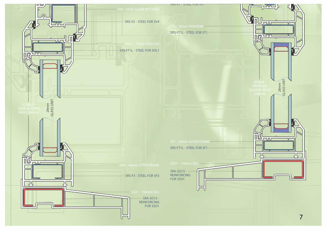
Key: =Plastic =Aluminium =Rubber =Steel =Foam =Glass =Sealant =Various/Other
28m
mG
LASS
UN
IT
5OJB28 -OGEE GLAZINGBEAD (28mm)
SchematicsSchematics
Internally BeadedCasement WindowInternally Beaded
Casement WindowExternally BeadedCasement WindowExternally BeadedCasement Window
5CJB28 -CHAMFERED
GLAZING BEAD(28mm)
28m
mG
LASS
UN
IT
5RS-V1 - STEEL FOR 5V1
5T1 - 32mm TRANSOM
5RS-FT1L - STEEL FOR 5T1
5F1 - 34mm OUTER FRAME
5RS-FT1L - STEEL FOR 5F1
5SO1 - 150mm SILL
5RA-SO13 -REINFORCINGFOR 5SO1
5V4 - OGEE GLAZE IN T SASH
5RS-V2 - STEEL FOR 5V4
5OL1 - 70mm ODD LEG
5RS-FT1L - STEEL FOR 5OL1
5F3 - 40mm OUTER FRAME
5RS-F3 - STEEL FOR 5F3
5SO1 - 150mm SILL
5RA-SO13 - REINFORCING
FOR 5SO1
7
28m
mG
LASS
UN
IT
5OJB28 -OGEE GLAZINGBEAD (28mm)
28m
mG
LASS
UN
IT
5PJB28 -PROFILED
GLAZING BEAD(28mm)
5F2 - 50mm OUTER FRAME
5RS-F2 - STEEL FOR 5F2
5T2 - 87mm TRANSOM
5RS-T2 - STEEL FOR 5T2
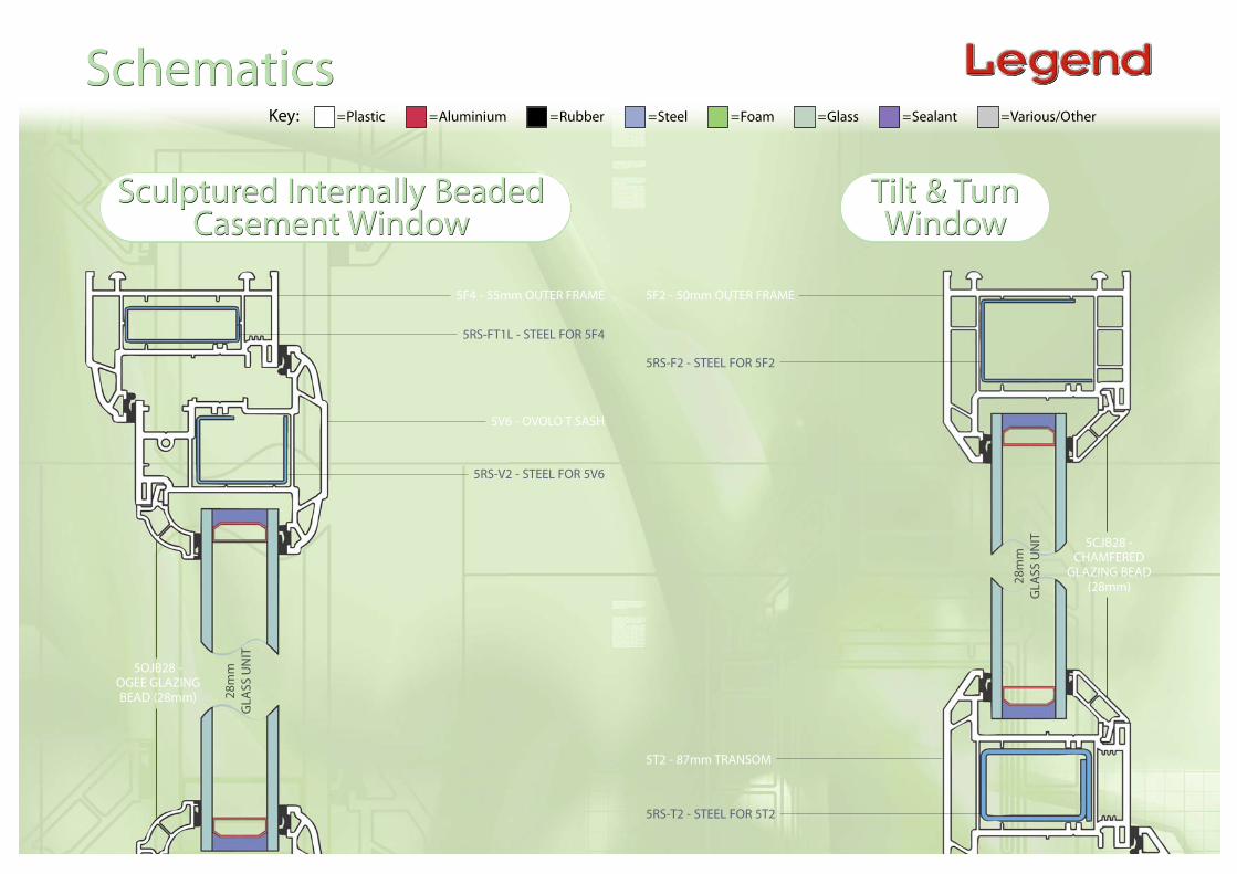
5F4 - 55mm OUTER FRAME
5RS-FT1L - STEEL FOR 5F4
5V6 - OVOLO T SASH
5RS-V2 - STEEL FOR 5V6
Key: =Plastic =Aluminium =Rubber =Steel =Foam =Glass =Sealant =Various/Other
28m
mG
LASS
UN
IT
5OJB28 -OGEE GLAZINGBEAD (28mm)
SchematicsSchematics
Sculptured Internally BeadedCasement Window
Sculptured Internally BeadedCasement Window
Tilt & TurnWindow
Tilt & TurnWindow
5CJB28 -CHAMFERED
GLAZING BEAD(28mm)28
mm
GLA
SS U
NIT

5TT1 - TILT & TURN VENT
5RS-TT1 - STEEL FOR 5TT1
5TT1 - TILT & TURN VENT
5RS-TT1 - STEEL FOR 5TT1
5F2 - 55mm OUTER FRAME
5RS-F2 - STEEL FOR 5F2
5SO1 - 150mm SILL
5RA-SO13 -REINFORCINGFOR 5SO1
5V6 - OVOLO T SASH
5RS-V2 - STEEL FOR 5V6
5OL3 - 66mm ODD LEG
5RS-T4H - STEEL FOR 5OL3
5F4 - 55mm OUTER FRAME
5RS-FT1L - STEEL FOR 5F4
5SO1 - 150mm SILL
5RA-SO13 - REINFORCING
FOR 5SO1
9
28m
mG
LASS
UN
IT
5OJB28 -OGEE GLAZINGBEAD (28mm)
28m
mG
LASS
UN
IT 5CJB28 -CHAMFERED
GLAZINGBEAD
(28mm)

5CD-F1 - COMPOSITE DOOROUTERFRAME
5RA-CDF1 - COMPOSITE DOOROUTERFRAME REINFORCEMENT
5CD-G2 - GLAZING GASKET
5CD-G2 - GLAZING GASKET
5CD-T1 - COMPOSITE DOORTRANSOM
5RA-CDT1 - COMPOSITE DOORTRANSOM REINFORCEMENT
5F2 - 50mm OUTER FRAME
5RS-F2 - STEEL FOR 5F2
5DV2 - T DOOR VENT
5RS-DV1 - STEEL FOR 5DV2
5DV2 - T DOOR VENT
5RS-DV1 - STEEL FOR 5DV2
Key: =Plastic =Aluminium =Rubber =Steel =Foam =Glass =Sealant =Various/Other
28m
mG
LASS
UN
IT 5OJB28 -OGEE
GLAZINGBEAD
(28mm)
SchematicsSchematics
DoubleDoor
DoubleDoor
CompositeDoor
CompositeDoor
5CD-FB28 -28mm FEATUREGLAZING BEAD28
mm
GLA
SS U
NIT
5CD-F1 - COMPOSITE DOOROUTERFRAME
5RA-CDF1 - COMPOSITE DOOROUTERFRAME REINFORCEMENT

5CD-G2 - WEATHERSEAL GASKET
5LT-CDS1 - SEAL CARRIER5CD-WS2 - BRUSH SEAL
5T1 - 70mm TRANSOM
5RS-FT1L - STEEL FOR 5T1
5DV2 - T DOOR VENT
5RS-DV1 - STEEL FOR 5DV2
5DV2 - T DOOR VENT
5RS-DV1 - STEEL FOR 5DV2
5F2 - 50mm OUTER FRAME
5RS-F2 - STEEL FOR 5F2
11
28m
mG
LASS
UN
IT
CO
MPO
SITE
DO
OR
PAN
EL
5OJB28 -OGEE
GLAZINGBEAD
(28mm)
5CD-WS1 -BRUSH SEAL
5CD-WS1 -BRUSH SEAL
CO
MPO
SITE
DO
OR
PAN
EL
CO
MPO
SITE
DO
OR
PAN
EL
CO
MPO
SITE
DO
OR
PAN
EL
5LTC1 - COVERSTRIP
5LT-CDDT1 - DRAIN TRAY
5LTC1 - COVERSTRIP
5LT-CDDT1 - DRAIN TRAY
44.0 44.0

5F2 - 40mm OUTER FRAME
5RS-F2 - STEEL FOR 5F2
5DV2 - T DOOR VENT
5RS-DV1 - STEEL FOR 5DV2
Key: =Plastic =Aluminium =Rubber =Steel =Foam =Glass =Sealant =Various/Other
28m
mG
LASS
UN
IT5CJB28 -CHAMFERED
GLAZINGBEAD
(28mm)
SchematicsSchematics
ResidentialDoor
ResidentialDoor
Patio HorizontalCross Section
Patio HorizontalCross Section
PF01 - OUTER FRAME
PR01 - OUTER FRAME REINFORCEMENT
PT01 - THRESHOLDWP02 - PATIO WOOL PILEPR07 - PACKER/BLOCK PACKER
PZ01 - SASH
PR02 - SASH REINFORCEMENT
PG01 - PATIO GASKET
PG01 - PATIO GASKET
PIO1 - INTER-LOCK COVER
AI02 - INTER-LOCK
PZ01 - SASH
PR02 SASH REINFORCEMENT
28m
mG
LASS
UN
ITWP02 - PATIOWOOL PILE
PB01 -28mmCO-EXBEAD

5T2 - TRANSOM
5RS-T2 - STEEL FOR 5T2
5DV2 - T DOOR VENT
5RS-DV1 - STEEL FOR 5DV2
5F2 - 40mm OUTER FRAME
5RS-F2 - STEEL FOR 5F2
5SO1 - 150mm SILL
5RA-SO13 - REINFORCING
FOR 5SO1
13
28m
mG
LASS
UN
IT
28m
mG
LASS
UN
IT
PB01 -28mmCO-EXBEAD
WP02 - PATIOWOOL PILE
AI02 - INTER-LOCKPIO1 - INTER-LOCK COVER
PG01 - PATIO GASKET
PG01 - PATIOGASKET
PZ01 - SASH
PR02 - SASH REINFORCEMENT
HANDLE (which may differbetween suppliers)
WP02 - PATIO WOOL PILE
PT01 - THRESHOLDPR05 - LOCK KEEP/
HARDWARE FIXING STRIP
PF01 - OUTER FRAME
PR01 - OUTER FRAME REINFORCEMENT
5CJB28 -CHAMFERED
GLAZINGBEAD
(28mm)

Key: =Plastic =Aluminium =Rubber =Steel =Foam =Glass =Sealant =Various/Other
SchematicsSchematics
70mm Coupling Details & Sizes70mm Coupling Details & Sizes
DIM A
5RA-LCM1
28.0
6.0 6.06mm packers
5EMG1
106.
0
DIM B
Seal to outer frame with silicone
5EMG1
5RA-EMC1
5RA-MPP1
5F1 5F3 5F2
5LB-TW - THERMAL WASHER
DIM A
5RA-MCM1
28.0
6.0 6.06mm packers
5EMG1
DIM B
Seal to outer frame with silicone
5EMG1
5RA-EMC1
5RA-MPP1
5F1 5F3 5F2
5LB-TW - THERMAL WASHER
137.
0
5RA-LCM15RA-LCM1 5RA-MCM15RA-MCM1
15
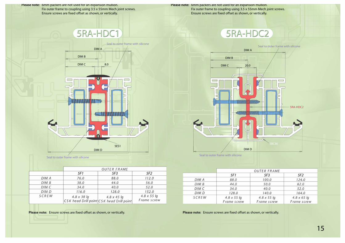
Please note: 6mm packers are not used for an expansion mullion.Fix outer frame to coupling using 3.5 x 55mm Mech joint screws.Ensure screws are fixed offset as shown, or vertically.
Please note: Ensure screws are fixed offset as shown, or vertically.
DIM A
Seal to outer frame with silicone
DIM B
DIM C 8.0
DIM D5ES1
Seal to outer frame with silicone
5F1 5F3 5F2
Please note: Ensure screws are fixed offset as shown, or vertically.
5F1 5F3 5F2
DIM ASeal to outer frame with silicone
DIM B
DIM C 20.0
5RA-HDC2
5BC36
Seal to outer frame with silicone
DIM D
Please note: 6mm packers are not used for an expansion mullion.Fix outer frame to coupling using 3.5 x 55mm Mech joint screws.Ensure screws are fixed offset as shown, or vertically.
5RA-HDC15RA-HDC1 5RA-HDC25RA-HDC2
16
Technical DataTechnical Data
Main Technical DetailsMain Technical DetailsName: Legend
3mm System for windows and doors
Grade Reference: SYN10 White 01
Material: Acrylic modified high quality impact resistant, white unplasticised Polyvinyl Chloride extrusion to produce a rigid multi-chamber extrusion.
Physical Properties: Comply with BS EN 12608 2003
Colours: Mahogany, White, Cherrywood, Light Oak,Anthracite Grey, Black Brown, Dark Red (Burgundy), Steel Blue (Oxford) and Dark Green (Brookland)
Appearance: Smooth, White, Non-porous gloss surface/Woodgrain
Surface Finish: Stabilised against UV light to prevent excessive colour shift. Meets requirements of BS EN 12608 when used in the EU Moderate climate.
Weldability: For the determination of the weldability of profiles, welded corners are tested in accordance with EN514. The calculated mean stress at maximum of each corner shall not be <25 N/mm2 for the tensile bending test of 35 N/mm2 for the compression bending test. Each individualvalue shall not be <20 N/mm2 for the tensile bending test and not be <30 N/mm2 for the compression bending strength.
Glass & Glazing: Subject to manufacture in accordance withthe Synseal Technical Manual recommendations, the casement window system will conform to the requirements ofthe standard.
Physical Properties of PVC-U Type A MaterialGrade Ref: SYN10 White 01
Sound Insulation: 30db minimum
Thermal Conductivity Typical test value 0.16 W/M deg C.at 20ºC: PVC-U has a low thermal conductivity and
virtually constant over a wide temperature range.
Heat Reversion: To BS EN 12608 Clause 5.5 (Test method: 1 hr at 100ºC). When tested in accordance with Appendix E, the mean maximum reversion value for individual samples shall not be greater than 2% for profiles and glazing beads.The variation between individual face sidesof the same sample shall not be greater than 0.4% for profiles and 0.6% for glazing beads.
Heat Ageing: To BS EN 12608 Clause 5.7 (Test method 30mins at 150ºC). When tested in accordance with Appendix F, the profile shall show no bubbles, cracks or de-lamination.
Resistance of impact To BS EN 12608 Clause 5.6 Class 2. (Test at low temperature: method: 1kg from 1.5 metres at -10ºC).
When mainframe, sub-sill casement and sash profiles are tested in accordance with EN 477, no more than one sample shall exhibit cracking through the entire wall thickness of the profiles on either face.
Heat Resistance/ To BS EN 12608. When tested to ISO 306 Softening Point: method B. Minimum vicat 5kg softening
point 75ºC. Typical result 82ºC. This is well above the requirements of the UK andGerman specifications.
Apparent Modulus To BS EN 12608 minimum requirement of Elasticity: 2200 mpa value, when tested to ISO 178.
Typical result 2350 mpa.
Retention of Impact To BS EN 12608 2003. Minimum 60% of Strength after Artificial original value specified when tested toAgeing: EN 513
Colour Fastness: After exposure in accordance with EN 513 moderate EU climate zone, the change in colour between the unexposed test specimens expressed in ∅ E* shall not be >5 & ∅ b* not >3. The determination of the change in colour is in accordance with EN 513.
Bulk Density of Typical test value 0.63 - 0.64. Minimum Powder Blend: requirements: None specified.
Specific Gravity of Typical test 1.472 6ms c.c.Profile: Minimum requirement: None specified.
PROFILE STORAGE
Prefabricated Storage:
The profiles should be stored in a suitable area, preferably undercover NOT in moist conditions or direct sunlight. If the profile isstored on racking, it must be supported at least 1 metre intervals ofthe entire profile length. If stored on the floor, the floor must be leveland the profile placed on a protective board base.
The ideal factory/storage temperature should be maintainedbetween 17ºC and 20ºC as working with profiles in colder conditionscan lead to undue weld stress. If the profile has been stored in a separate storage area with lowertemperature, at least one hour per ºC should be allowed for the profileto reach workshop temperature.
Profile cut ready for welding shall be stored in a dry area with thesame ambient temperature of 17ºC - 20ºC. Care shall be taken ifprofiles are stored vertically so as not to damage the point of themitres (check contamination of these points prior to welding).All cut profiles must be welded within 48 hours as this will avoidcontamination of the cut ends and avoid any absorption of moisture,which could have an effect on the weld strength.

17
Available Profile Colours*Available Profile Colours*
Dark Green (Brookland)6125
Anthracite Grey7016
Black Brown8518
Dark Red (Burgundy)3081
Steel Blue (Oxford)5150
WhiteC154
Mahogany(Also available for roofs)
2097013
Golden Oak(Also available for roofs)
80001
Cherrywood(Also available for roofs)
8015/16/17
*Please note: The swatches on this page should be used as a guide only and are as accurate as our printing process allows

The linear thermal expansion of a material is ameasure of how much that material will expand foreach 1 degree change in temperature.
Typical values:
PVC-U: 0.0000600/ºC
Mild Steel (0.06 carbon): 0.0000126/ºC
Aluminium (99 % pure): 0.0000240/ºC
The values of the coefficient of thermal expansioncan be regarded as constant over the temperaturerange normally experienced in the U.K.
A temperature difference between the inside andoutside surfaces can lead to differential thermalexpansion, which may in some circumstances leadto buckling or distortion.
The bulk temperature of the material is usually usedto calculate the expansion. This is not always thesame as the surface temperature.
For white profile the temperatures areapproximately the same, but for dark (woodgrain)profiles the bulk temperatures may be higher thanthe air temperature due to the higher solar heatgain of dark profiles. Expansion gaps should alwaysbe larger for woodgrain profiles than for whiteprofiles to allow for this.
Calculation example:
If a 1000 mm length of PVC-U profile is heated upfrom 20ºC to 40ºC, then the expansion is given by:
Original length X change in temperature Xcoefficient of thermal expansion, i.e.
1000 x 20 x 0.00006 = 1.2 mm.
Therefore the final length of the PVC-U profile is1001.2 mm.
Conversion Table - Wind Pressure and Speed
Note: The above conversions are based on the aerodynamic relationship:
Pressure = (velocity)2 x (a constant)
For design wind pressures these values must be multiplied by a shape factor.
18
Technical DataTechnical Data
Thermal Expansion of PVC-UThermal Expansion of PVC-U(Information from Tangram Technology Ltd)
Exposure CategoriesExposure Categories

Sample Style:Casement
Fixed Light/Side Hung
Blue line illustratesopening light length
(air leakage)
19
‘U’ - Values and Energy Ratings‘U’ - Values and Energy Ratings(From computer simulations)
4-20-4 Clear Float, Argon, K-glass & Standard Spacer
Window ‘U’ - Value = 1.8296 W/m2K
Domestic Window Energy Rating (D W E R )
Pane g%
F gL DWER
⊥ glass w wfactor
W/m2 K kWH/m2/YrLeft 0.72 37.76
0.9 0.4493 0.01 -27.80Right 0.72 31.57
AB
CD D
EF
G
0-10-20-30-50-70
4-20-4 Planitherm Total, Argon, Diamant & Edgetech Super Spacer
Window ‘U’ - Value = 1.41 W/m2K
Domestic Window Energy Rating (D W E R )
Pane g %
F g L DWER
⊥ glass w wfactor
W/m2 K kWH/m2/YrLeft 0.71 39.57
0.9 0.44 0.13 -0.40Right 0.71 29.79
0-10-20-30-50-70
4-20-4 Clear Float, Argon, K-glass & Edgetech Super Spacer
Window ‘U’ - Value = 1.6302 W/m2K
Domestic Window Energy Rating (D W E R )
Pane g%
F gL DWER
⊥ glass w wfactor
W/m2 K kWH/m2/YrLeft 0.72 37.76
0.9 0.4493 0.01 -14.14Right 0.72 31.57
AB
C CD
EF
G
0-10-20-30-50-70
4-20-4 OptiWhite, Argon, K-glass & Edgetech Super Spacer
Window ‘U’ - Value = 1.6117 W/m2K
Domestic Window Energy Rating (D W E R )
Pane g%
F gL DWER
⊥ glass w wfactor
W/m2 K kWH/m2/YrLeft 0.78 37.76
0.9 0.4867 0.01 -4.69Right 0.78 31.57
AB B
CD
EF
G
0-10-20-30-50-70
A ABCDEFG
SectionF1 fixed sill 0.0540 1.3560 0.0308 0.0417 0.0260 0.5250 0.0137
F2 fixed head 0.0540 1.3560 0.0308 0.0417 0.0260 0.5250 0.0137
F3 fixed jamb 0.0540 1.3560 0.0770 0.1044 0.0260 1.3720 0.0357
F4 + F5 sash sill 0.1035 1.4698 0.0543 0.0798 0.0260 0.4260 0.0111
F6 + F7 sash head 0.1035 1.4698 0.0543 0.0798 0.0260 0.4260 0.0111
F8 + F9 sash jamb 0.1035 1.6244 0.1425 0.2314 0.0270 1.2730 0.0344
F10 + F11 mullion 0.1215 1.7255 0.1681 0.2901 0.0540 1.3225 0.0714
0.5578 0.8691 0.1909Totals Total
bf(with gaskets)
(m)
Uf
W/(m2-K)
Frameareas
(gaskets)m2
Heat flow
W/K
ψ
W/(m-K)
lg(m)
Heat flow
W/K
Air Leakage loss:Air leakage at 50 Pa per hour & per unit length of opening light (BS 6375-1) - 2DP 0.13 m3/(m-h)Opening light length 3.7940 m Total air leakage 0.493 m3/h
L50 0.27 m3/(m-h) Heat loss = 0.0165 L50 0.00 W/(m2K)
F2
FixedLight
OpeningLight
Ag1 Ag2
Not to scale
bw
lw
1
/2 bw
F6F7
F5F4F1
F3 F10
F11
F9 F8
Frame:

43mm dia BAY POLE - 5RA-BP2Data supplied by Blencowe Associates Ltd - Structural Engineers - Uttoxeter
Material 6063 T6 - Limiting Stress po = 160N/mm2
SLENDERNESS RATIO AND MAXIMUM PERMISSIBLE STRESS (ALUMINIUM GRADE 6063 T6)(From BPF Code of Practice for the Survey of PVC-U Windows and Doorsets)
Key: =Aluminium
Bay-Pole Load-Bearing Capacity
The load-bearing capacity of a bay pole depends upontwo factors:
1. the Least Radius of Gyration,2. the Effective Length of the pole.
The Least Radius of Gyration is given by:
r = square root (I/A) where I is the moment of inertia (least axis) and A is the cross-sectional area of the pole.
The Effective Length of a pole is determined by thefixings at it's ends. If the pole is held in position at bothends, but not restrained in direction, then the EffectiveLength is the actual length of the pole (usually the casefor most poles).
If the pole is effectively held in position and restrainedat both ends, then the Effective Length is only 70% ofthe actual length (this condition will only apply if thepole is fixed to the structure so that it will not moveuntil the column starts to buckle).
The Slenderness Ratio of the bay pole can then becalculated by dividing the Effective Length by the LeastRadius of Gyration. The maximum permissible stress forthat length of bay pole can then be obtained from thegraph below. The actual load that can be applied is thengiven by multiplying the allowable stress by the cross-sectional area.
(We have done this for the most commonly usedSynseal bay poles and posts, see tables and graphs inthis section).
Technical DataTechnical Data
Safe Working Capacities of Bay-Poles & PostsSafe Working Capacities of Bay-Poles & Posts(Ref. BPF Publication - Code of Practice for the Survey of PVC-U Windows and Doorsets)
Cross section:
SLENDERNESS RATIO
MA
X P
ERM
ISSI
BLE
STR
ESS
POLE LENGTH (mm) - Under side of base plate to top of window frame
SAFE
WO
RKIN
G C
APA
CIT
Y (k
N)
HEIGHT (mm) SLENDERNESS PERMISSIBLE STRESS UNFACTORED F.O.S FACTOREDRATIO (N/mm2) CAPACITY (kN) CAPACITY (kN)

21
135º CORNER POST - RA135SData supplied by Blencowe Associates Ltd - Structural Engineers - Uttoxeter
Material 6063 T6 - Limiting Stress po = 160N/mm2
43mm dia BAY POST - 5RA-CP901Data supplied by Blencowe Associates Ltd - Structural Engineers - Uttoxeter
Material 6063 T6 - Limiting Stress po = 160N/mm2
Cross section:
HEIGHT (mm) SLENDERNESS PERMISSIBLE STRESS UNFACTORED F.O.S FACTOREDRATIO (N/mm2) CAPACITY (kN) CAPACITY (kN)
POLE LENGTH (mm) - Under side of base plate to top of window frame
SAFE
WO
RKIN
G C
APA
CIT
Y (k
N)
Cross section:
HEIGHT (mm) SLENDERNESS PERMISSIBLE STRESS UNFACTORED F.O.S FACTOREDRATIO (N/mm2) CAPACITY (kN) CAPACITY (kN)
POLE LENGTH (mm) - Under side of base plate to top of window frame
SAFE
WO
RKIN
G C
APA
CIT
Y (k
N)

Technical DataTechnical Data
Introduction:
PVC-U exhibits excellent fire behaviour and does not burn once the sourceof heat or flame has been removed.
Building Regulations:
UK Building Regulations do not stipulate any fire performance standardsfor the material used in window frames. Whilst no degree of 'fire resistance'(as defined by BS 476 part 8) can be achieved by PVC-U window units, thelarge scale fire tests carried out show no difference between PVC-U andwood under the conditions of test.
PVC-U can, when correctly formulated, achieve high ratings (usually Class 1surface spread of flame) when performance is assessed to BS 476: parts 6and 7.
Ignition and burning response:
PVC-U is very difficult to ignite using commonly available ignition sources(match, blow-lamp, etc). Tests with a wide variety of sources varying in heatintensity and impingement area on PVC-U window frames show that theproduct only burns whilst the source is applied. When the source isremoved there is no residual flame on the product. In terms of ignitability,the temperature required to ignite PVC-U is more than 120ºC higher thanthat of pinewood (385ºC for PVC-U and 260ºC for wood as defined for selfignition.) Once a material has been ignited the flammability can be definedin terms of the Limiting Oxygen Index (LOI) test.
This defines the amount of oxygen that needs to be present for a materialto burn freely. A material with an LOI of 21 will burn freely in air (whichcontains 21% oxygen) and one with an LOI of more than 21 will not burnin air at room temperature.
PVC-U has an LOI of approximately 50, compared with wood at an LOI of21. This shows that PVC-U will not sustain combustion in air at roomtemperature and is better than wood in this test.
The limited burning of PVC-U is confirmed in a variety of other standardtests which measure specific parameters, such as rate of heat release andflame spread under different conditions.
The conclusions are clear:
1) the rate of heat release and total heat released by PVC-U are significantlylower than most other building materials.
2) when flames do contact PVC-U, it forms a protective charred layer whichinsulates the material below and excludes the oxygen necessary forcombustion. This restricts the burning zone. In addition, any HCl emittedacts as a combustion inhibitor.
3) PVC-U is very difficult to ignite using common ignition sources.
Smoke and fumes:
Smoke is the result ofincomplete burning of amaterial and consists of solidor liquid particles in thecombustion gases. Smokedensities are similar to woodunder smouldering conditions,but greater under flamingconditions. The combustiongases (e.g. HCl) may lead tosome corrosion of metallicmaterials but restoration isnormally possible. Thecorrosion gases have no effectson the structural elements ofthe building. The toxic potencyof the combustion gases of PVC-U is similar to, and certainly notsignificantly worse than, those of many natural materials. The build up oftoxic fumes will be slow compared with rapidly burning materials of asimilar toxic potency.
The rate of generation and quantity of smoke and fumes produced by aPVC-U window will depend on the severity of the source applied. Thesmoke and fumes emitted will be confined to the area of the productaffected by the source and their transport away from the impingementzone will depend on local factors such as ventilation and survival of theglazing.
In a typical domestic fire the PVC-U window frames will not materiallyaffect the progress of the fire or the possibility of personal injury. Mostdeaths in fires are caused by smoke or fume inhalation. In a typicaldomestic fire the occupants are likely to suffer from the inhalation effectsfrom burning carpets, settees, curtains, etc. before the PVC-U in the windowframes has even begun to emit smoke or fumes.
Fire resistance:
The fire resistance of a glazed window is mainly influenced by the fracturebehaviour of the glazing at high temperature. The fire resistance of glazedPVC-U window frames is generally found to be similar to that of glazedwood window frames.
Large scale fire tests:
In a research programme carried out by the Fire Research Station, theperformance of PVC-U window frames in fires was compared with that oftraditional wood frames in a typical domestic room. All windows weredouble glazed and both a large fuel load/non-ventilated controlled fireand a medium fuel load/ventilation controlled fire were used.
The conclusions of the report were;
1) little damage was evident to both PVC-U and wood windows until theglass panes were displaced at approximately 250ºC to 400ºC. Glass panesfailed by cracking and falling out in a random manner.
2) after failure of one glass pane, the increased ventilation changed themode of the fire and accelerated the fire growth. In most tests the otherpanes fell out soon after.
3) wood frames burned after the displacement of the glass while thePVC-U window frames softened and the casement sometimes fell out.There was some evidence of combustion of the PVC-U, but PVC-U windowsdid not show any aspects of performance which would create new hazardsin fire involving buildings.
4) carbon monoxide, produced mainly from the wooden fuel under lowventilation conditions, was the major toxic hazard in each test and wasproduced in volumes that would prove lethal in regions where ambienttemperatures would allow survival.
5) the concentrations of carbon monoxide were noticeably lower in the fireinvolving only PVC-U frames; this was possibly caused by a lower rate ofburning in this test.
Summary:
The base PVC-U material has good fire properties and PVC-U windows givea satisfactory performance in fires compared with other materials.
PVC-U Windows in FiresPVC-U Windows in Fires(Information from Tangram Technology Ltd)
22

23
A guide to frame size limits for the coupling mullions on the SynsealLegend 70mm system has been plotted on pages 24 to 25 usingtriangulated wind load areas to give maximum deflections of L/175.
Step 1
Establish wind load area width X and load span L as shown below.
Please note that the maximum load area width X for each side ofcoupling mullion is half load span L.
NOTE: X denotes wind load area width. L denotes load span.
Step 2
Refer to charts on pages 24 or 25.
Select applicable load span from horizontal axis. Select applicationload width from vertical axis. Mark the intersection point.
Coupling mullion required will be indicated by the area theintersection point lies in.
Example: Load span L = 2800. Wind load area width X = 2000.Mark intersection point and use coupling mullion indicated by the area the intersection point lies in.Therefore, coupling mullion 5RA-LCM1 must be used.
Frame Limits for Coupling MullionsFrame Limits for Coupling Mullions
1500 2500
45º 45º
2800
L
750 1250
2000 X
O/f
ram
e h
eig
ht
2000
Intersection point
Load
are
a w
idth
X
Load span L
2800
Coupling Mullion5RA-LCM1
Coupling Mullion5RA-LCM1

Technical DataTechnical Data
Size Limits for Coupling Mullions (including H/Duty Coupling Mullions)Size Limits for Coupling Mullions (including H/Duty Coupling Mullions)Size Limits for H/Duty Coupling Mullions
at 1200Pa wind load (100MPH wind speed)
Load Span (mm)
Load
Wid
th (m
m)
Heavy Duty Coupling Mullion - 5RA-HDC2
Heavy Duty Coupling Mullion - 5RA-HDC1
Size Limits for Coupling Mullionsat 1200Pa wind load (100MPH wind speed)
OUT OF LIMITS
Load Span (mm)
Load
Wid
th (m
m)
CouplingMullion
5RA-LCM1
CouplingMullion
5RA-LCM1 +Reinforcing
CouplingMullion
5RA-MCM1
24
25
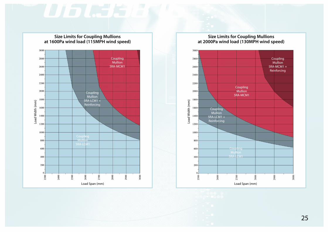
Size Limits for Coupling Mullionsat 1600Pa wind load (115MPH wind speed)
Size Limits for Coupling Mullionsat 2000Pa wind load (130MPH wind speed)
Load
Wid
th (m
m)
Load
Wid
th (m
m)
Load Span (mm) Load Span (mm)
CouplingMullion
5RA-LCM1
CouplingMullion
5RA-LCM1 +Reinforcing
CouplingMullion
5RA-MCM1
CouplingMullion
5RA-LCM1
CouplingMullion
5RA-LCM1 +Reinforcing
CouplingMullion
5RA-MCM1
CouplingMullion
5RA-MCM1 +Reinforcing

26
Introduction:
In addition to their primary function as visual openings, windows also
transmit sound. This is of concern not only for the exterior surfaces of
a building, but also for interior applications ranging from office doors
to control booths in recording studios. Sound transmitted through
windows often limits the overall acoustical insulation.
Sound transmission through windows is governed by the same
physical principles that affect walls, but practical noise control
measures are influenced by the properties of glass and the
characteristics of the window assemblies. Increasing the glass
thickness, for example, gives greater noise reduction at most
frequencies, but the stiffness of glass limits the improvement. Using
multiple layers (double or triple glazing) increases noise reduction at
most frequencies, but this is dependent on the separation of the
layers.
As with other building assemblies, transmission of sound through
cracks may drastically reduce the effective noise reduction. This is of
particular concern for openable windows: even windows with good
weather-stripping have reduced noise reduction because of air
leakage. Most of the data presented in this report are for sealed
windows.
The acoustic terms used in this report are as follows:
decibels (abbreviated to dB.)
Sound Transmission Loss (TL) which is a standardised measure of the
noise reduction in decibels for specific frequency ranges.
Sound Transmission Class (STC) is a single figure rating of sound
transmission, calculated by fitting a standard contour to the TL data.
It is most commonly used in North America.
Sealed double glazing:
The TL of double glazing is strongly dependent on the features of the
cavity between the two layers of glass. The STC rating increases as the
air space increases (see fig. 1 on page 27). For each doubling of the
air space, the STC increases by approximately 3. The STC also
increases with increasing glass thickness.
If the separation between the panes is small, the STC rating is only
slightly higher than that for a single pane of the same glass. This
occurs because the air in the space between the two panes acts like
a spring, transferring vibrational energy from one pane to the other.
This resonance falls within the range of 200 to 400 Hz for a unit with
a small air gap (see fig. 2 on page 27). Most of the energy from aircraft
or heavy traffic falls within this frequency range, but by increasing the
air space and using heavier glass, the resonant frequency can be
lowered to improve the insulation against such noise sources.
Sealed triple glazing:
Despite the widespread belief that adding another layer of glass
must be beneficial, triple glazing provides essentially the same noise
reduction as double glazing, unless the air gap is very large. Figure 3
(on page 27) compares TL data for a double glazed window with that
for a triple glazed window of similar total thickness.
Designing for noise control:
In most cases where substantial noise control is required, double
glazing is the most sensible choice. The airspace should be
sufficiently large to provide the desired TL.
Using different thicknesses of glass for double glazing gives greater
noise reduction. The highest STC values shown in figure 2 are for
double 6mm glass; windows with 3mm substituted for one of the
6mm panes would have equal or higher STC ratings.
The use of laminated glass has also been shown to reduce sound
transmission.
Technical DataTechnical Data
Sound Transmission Through WindowsSound Transmission Through Windows(Ref. Canadian Building Digest, article by J. D. Quirt)

27
Figure 1.
Sound transmission class (STC)versus interpane spacing fordouble glazing
SOU
ND
TRA
NSM
ISSI
ON
CLA
SS
50
45
40
35
30
255 10 20 50 100 200
INTERLAYER SPACING, mm
4mmglass
6mm glass
3mm glass
Figure 2.
The effect of a small airspaceon TL of double glazing
50
40
30
20
10125 250 500 1k 2k 4k
FREQUENCY, Hz
TRA
NSM
ISSI
ON
LO
SS, d
B
Single 3mm glass(STC 30)
Double 3mm glass6mm air space(STC 30)
Figure 3.
TL of double and tripleglazed windows
50
40
30
20
10125 250 500 1k 2k 4k
FREQUENCY, Hz
TRA
NSM
ISSI
ON
LO
SS, d
B
2 layers of 3mm glass with12mm air space (STC 31)
3 layers of3mm glasswith 6mmair spaces(STC 31)

Synseal Extrusions Limited, Common Road, Huthwaite, Sutton-in-Ashfield, Notts. NG17 6AD
Tel: (01623) 443200 Fax: (01623) 555330
www.synseal.co.uk
Legend is a Synseal product