lego rcx programmers guide ================== · runtime kernel based on "legos 0.2.4"...
TRANSCRIPT

1
============================
Lego "RCX Programmer"s Guide
============================
(c) Dany Senn, March 2012 _______________________________________________________________________ 1. Introduction ============ The "RCX Programmer" let's you program the "RCX Brick" on the fly like a pocket calculator using its own screen. The yellow Lego RCX Brick +-------------------------+ |View 1 2 3 Prgm| |[__] +-----------+ [__]| | | 00.PA [ | | |OnOff +-----------+ Run | |[__] A B C [__]| +-------------------------+ The idea is based on "OnScreen" Copyright(c)1999 by David R. van Wagner, and "LegOS 0.2.4" Copyright(c)1998 by Markus L. Noga. However, the code (firmware) for the Lego "RCX Programmer" has been completely rewritten to provide much more and enhanced functionality. Lego "RCX Programmer" Features: * RCX Standalone/Pocket Programmer with 256 Program Steps * 22 Powerful RCX Commands (GOto, PAUSe, INput, OUput, LOop, ...) * 16 Registers (8-bit) for processing input/output data, etc. * 20 Register Operations (LDD/STD/IN/OUT..ADD/SUB/MUL/DIV..AND/OR..) * Conditional Branching (BEQ/BNE/BCC/BHI/BLO...) * Subroutines (JSR/RTS) * 256 Byte Memory Area (for User Variables/Data) * Single Step Execution Mode * VLL Communication (send VLL codes to MicroScout & CodePilot) * IR Communication (send/receive Messages & Remote Commands)

2
2. Requirements ============ a) The "Lego RCX Brick" and the "Lego RCX IR Tower" These were part of the "Lego Mindstorms Robotics Invention System" which required a Windows 95/98 PC to install the "Lego Mindstorms RIS" software and the "Lego RCX Software Development Kit" (RCX-SDK) in order to write and download user programs. Unfortunately, the are no further software updates available neither for RIS nor for the RCX-SDK from Lego's website which would support new Windows operating system releases, or support other development platforms such as Linux, or Mac OS X. Fortunately, there are many alternate open source projects around, which allow you to continue to program the "RCX Brick" using newer development platforms such as Windows XYZ, Linux, or Mac OS X. However, you would still require such a platform to write and download programs for the RCX. This is where the "RCX Programmer" steps in; it makes the RCX less dependent on future PC platform support by enabling the RCX to be used as it's own standalone development kit. You only would need to be able to download the special "RCX Programmer" firmware using the "IR Tower" supplied with the "Lego Mindstorms Robotics Invention System". Once the "RCX Programmer" firmware has been downloaded to the "RCX Brick", you do not need a PC/Mac anymore to create and develop your own Lego RCX programs. Unfortunately, the RCX has no Flash Memory to store its firmware and user programs. If the batteries are exhausted, removed, or replaced, you will need to download the "RCX Programmer" firmware again using a PC or Mac and a small download tool which is provided with the "RCX Programmer". b) Firmware Download Tool As mentioned above you'll need a tool (executable) to download the "RCX Programmer" firmware (rcx.srec) to the "RCX Brick". This firmware is different from the original Lego firmware (firm0309.lgo) which includes the Lego RCX Runtime Executive and the RCX Byte Code Interpreter. The new "RCX Programmer" firmware consists of its own runtime kernel based on "legOS 0.2.4" and the code which enables you to create and execute your own programs on the RCX screen. There are several options to download the firmware: * Windows 96/98/.. with "BricxCC" installed, or "BrickTool.exe" * Linux using either "LegOS" (now "brickOS"), or "RCXtools" * Max OS X using the "RCXtools for Mac" You may search the Internet for above key words to find a similar tool for your platform, or search for "Lego RCX firmware tool".

3
3. Installation ============ The instructions are for Windows 95/98 but would be similar for other platforms using the above mentioned tools. a) Open a DOS shell and create a directory where you want to install the "RCX Programmer" files: c:\windows> c:\windows> cd .. c:\> c:\> md rcx c:\> cd rcx c:\rcx> b) Unzip and copy the RCX files from the CD-ROM (d:) or any other media to the newly created directory: c:\rcx> copy d:\rcx\*.* c) Reset the "RCX Brick" by removing the batteries (this will clear any currently loaded firmware). Wait a minute then re-insert the batteries and switch the "RCX Brick" on: RCX Brick with no firmware +-------------------------+ |View 1 2 3 Prgm| |[__] +-----------+ [__]| | | !1| | |OnOff +-----------+ Run | |[__] A B C [__]| +-------------------------+
Note: ! = Lego Man standing If the "RCX Brick" is cleared (no firmware loaded) it shows only the Lego man standing and the number 1 at the right most position on the screen. Otherwise, if you see something like "00.00" the Lego firmware may still be loaded. d) Insert the 9V battery into the Lego RCX "IR Tower" and connect it to your PC via the serial communication cable. Make sure that the battery is good, otherwise the download may fail. e) Place the "RCX Brick" in front of the "IR Tower" (about 10cm apart) and enter the following command (COM1 assumed): c:\rcx> bricktool /com=COM1 -firmware=rcx.srec The green LED on the "IR Tower" should light up, and after some seconds the "RCX Brick" will show the number of blocks received. The download may take several minutes to complete.
4
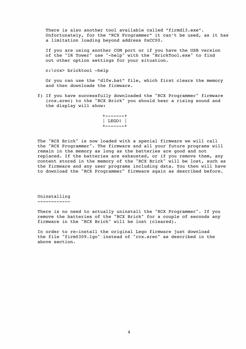
There is also another tool available called “firmdl3.exe”. Unfortunately, for the “RCX Programmer” it can’t be used, as it has a limitation loading beyond address 0xCC00. If you are using another COM port or if you have the USB version of the "IR Tower" use "-help" with the "BrickTool.exe" to find out other option settings for your situation. c:\rcx> bricktool –help Or you can use the “dlfw.bat” file, which first clears the memory and then downloads the firmware. f) If you have successfully downloaded the "RCX Programmer" firmware (rcx.srec) to the "RCX Brick" you should hear a rising sound and the display will show: +-------+ | LEGO! | +-------+ The "RCX Brick" is now loaded with a special firmware we will call the "RCX Programmer". The firmware and all your future programs will remain in the memory as long as the batteries are good and not replaced. If the batteries are exhausted, or if you remove them, any content stored in the memory of the "RCX Brick" will be lost, such as the firmware and any user programs including data. You then will have to download the "RCX Programmer" firmware again as described before. Uninstalling ------------ There is no need to actually uninstall the "RCX Programmer". If you remove the batteries of the "RCX Brick" for a couple of seconds any firmware in the "RCX Brick" will be lost (cleared). In order to re-install the original Lego firmware just download the file "firm0309.lgo" instead of "rcx.srec" as described in the above section.
5
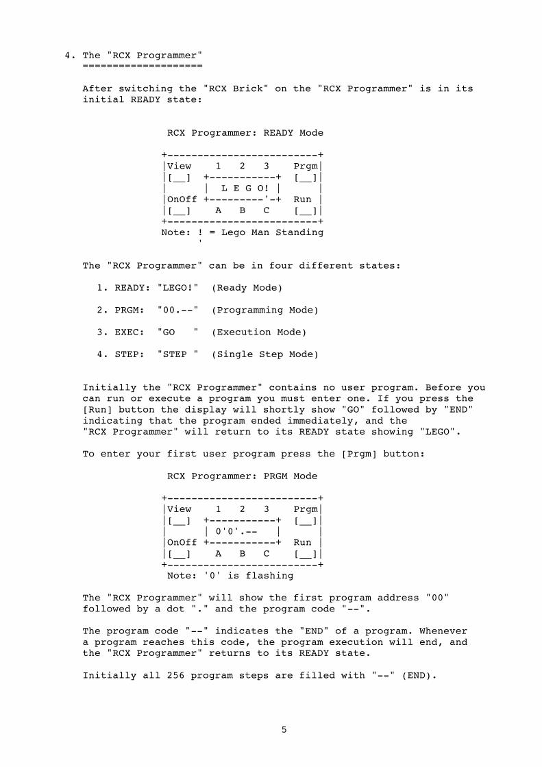
4. The "RCX Programmer" ==================== After switching the "RCX Brick" on the "RCX Programmer" is in its initial READY state: RCX Programmer: READY Mode +-------------------------+ |View 1 2 3 Prgm| |[__] +-----------+ [__]| | | L E G O! | | |OnOff +---------'-+ Run | |[__] A B C [__]| +-------------------------+ Note: ! = Lego Man Standing ' The "RCX Programmer" can be in four different states: 1. READY: "LEGO!" (Ready Mode) 2. PRGM: "00.--" (Programming Mode) 3. EXEC: "GO " (Execution Mode) 4. STEP: "STEP " (Single Step Mode) Initially the "RCX Programmer" contains no user program. Before you can run or execute a program you must enter one. If you press the [Run] button the display will shortly show "GO" followed by "END" indicating that the program ended immediately, and the "RCX Programmer" will return to its READY state showing "LEGO". To enter your first user program press the [Prgm] button: RCX Programmer: PRGM Mode +-------------------------+ |View 1 2 3 Prgm| |[__] +-----------+ [__]| | | 0'0'.-- | | |OnOff +-----------+ Run | |[__] A B C [__]| +-------------------------+ Note: '0' is flashing The "RCX Programmer" will show the first program address "00" followed by a dot "." and the program code "--". The program code "--" indicates the "END" of a program. Whenever a program reaches this code, the program execution will end, and the "RCX Programmer" returns to its READY state. Initially all 256 program steps are filled with "--" (END).
6
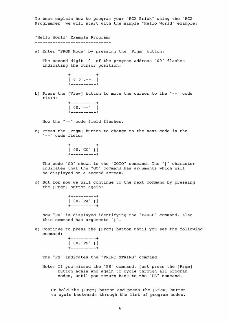
To best explain how to program your "RCX Brick" using the "RCX Programmer" we will start with the simple "Hello World" example: "Hello World" Example Program: ------------------------------ a) Enter "PRGM Mode" by pressing the [Prgm] button: The second digit '0' of the program address "00" flashes indicating the cursor position: +----------+ | 0'0'.-- | +----------+ b) Press the [View] button to move the cursor to the "--" code field: +----------+ | 00.'--' | +----------+ Now the "--" code field flashes. c) Press the [Prgm] button to change to the next code in the "--" code field: +----------+ | 00.'GO' [| +----------+ The code "GO" shown is the "GOTO" command. The "[" character indicates that the "GO" command has arguments which will be displayed on a second screen. d) But for now we will continue to the next command by pressing the [Prgm] button again: +----------+ | 00.'PA' [| +----------+ Now "PA" is displayed identifying the "PAUSE" command. Also this command has arguments "[". e) Continue to press the [Prgm] button until you see the following command: +----------+ | 00.'PS' [| +----------+ The "PS" indicates the "PRINT STRING" command. Note: If you missed the "PS" command, just press the [Prgm] button again and again to cycle through all program codes, until you return back to the "PS" command. Or hold the [Prgm] button and press the [View] button to cycle backwards through the list of program codes.

7
f) Then at the "PS" command press the [View] button: +----------+ | '0'0 ]| +----------+ This will change to the arguments screen of the "PS" command. The end of the argument field is marked by "]". So every command with arguments actually uses two screens: Screen: 1 Screen: 2 +----------+ +----------+ | 00.'CC' [| | 0.0.00 ]| +----------+ +----------+ addr.code [ arguments ] The [View] button always advances to the next field and after all arguments returns back to the address "00" and code "CC" fields. You can move the cursor back to a previous field by holding [View] and pressing [Prgm]. But now let's return to our "PS" command and its argument: g) The "PS" command has one argument which is a two digit (byte) index identifying a preprogrammed text string. There are many predefined text strings available, and we will select the string "HELLO" which has the index "38": +----------+ | '3'0 ]| +----------+ Press the [Prgm] button as many time until "3" is displayed. Then press [View] to advance to the next digit of the argument: +----------+ | 3'8' ]| +----------+ Repeat pressing [Prgm] until '8' is displayed. h) To return to the address and code filed just press the [View] button again: +----------+ | 0'0'.PS [| +----------+ This completes your first program code entry.

8
i) To enter the next command press the [Prgm] button: +----------+ | 0'1'.-- [| +----------+ This will show you the next program address "01". It contains the code "--" (END). If we would execute this program now, the text "HELLO" would be displayed very shortly followed by the "END" text, as the program reaches its end. So we need to add a short "PAUSE" command to get time to read the text. j) Advance to the code field by pressing the [View] button: +----------+ | 01.'PA' [| +----------+ Press the [Prgm] button twice to select the "PA"(PAUSE) command. Press [View] to enter the argument screen: +----------+ +----------+ | 01.PA [| -> |'0'.0.00 ]| +----------+ +----------+ Skip to the last digit of the last argument by pressing [View] three times: +----------+ |0.0.0'0' ]| +----------+ Press [Prgm] to increment the value of the last digit to "1": +----------+ |0.0.0'1' ]| +----------+ Then press [View] to return to the address and code screen: +----------+ | 0'1'.PA [| +----------+ This completes the program step 2. Note: For now you don't need to know the meaning of the values you entered for the arguments. This will be explained in more detail in the "Command Reference" section.

9
k) Although, our program is not quite finished, we could give it a try and see what happens when we execute it. To execute the program we must first exit the "PRGM Mode" by pressing [Run]: +--------+ | LEGO! | +-----'--+ The "RCX Programmer" returns to its READY state. Now press [Run] again to execute the program we've just entered: +--------+ | HELL;O | +-----^--+ Note: ; = Lego Man walking ^ You should see the word "HELLO" for about one second before the program finishes with "END" and returns to the READY state. You may have also encountered that the Lego man is walking while a program is running. l) We also want to add the word "World" to our little program: Press [Prgm] to enter "PRGM Mode" then select the next free program address with the [Prgm] button: +----------+ | 0'2'.-- | +----------+ Advance to the code field by pressing [View] and then [Prgm] until the "PS" command is shown: +----------+ | 02.'PS'[| +----------+ Skip to the argument screen by pressing [View]: +----------+ +----------+ | 02.PS [| -> | '0'0 ]| +----------+ +----------+
Enter "39" by pressing [Prgm] until "3" is shown, then [View] followed by "9": +----------+ +----------+ | 02.PS [| -> | 3'9' ]| +----------+ +----------+ Return back to the address and code field by pressing [View].

10
m) Advance to the program address "03" and enter another one second pause command as described in step i) and j). +----------+ +----------+ | 03.PA [| -> | 0.0.0'1']| +----------+ +----------+ n) Then press [Run] to return to the READY state and again [Run] to execute your program: +--------+ +--------+ +--------+ +--------+ | HELL;O | -> | UOrL;d | -> | END ; | -> | LEGO! | +-----^--+ +-----^--+ +-----^--+ +-----^--+ If you entered the program correctly, you should see the word "HELL O" followed by "UOrL d", then "END" and finally "LEGO" as the program ends. o) We also want the program to repeat the message again and again. For this, we need to add a "GO" (GOTO) command at the end of our program to jump back to address "00" and repeat the hole code. Press [Prgm] to enter "PRGM Mode" then select the next free address code: +----------+ +----------+ | 04.GO [| -> | 00 ]| +----------+ +----------+ You don't need to enter the argument address "00" as it is the default value of the "GO" command. p) Return to the READY state by pressing [Run] and [Run] again to execute the program: Your program should now circling displaying the words "HELL O" ... "UOrL d" endlessly. To stop the program press [Run] again.
11
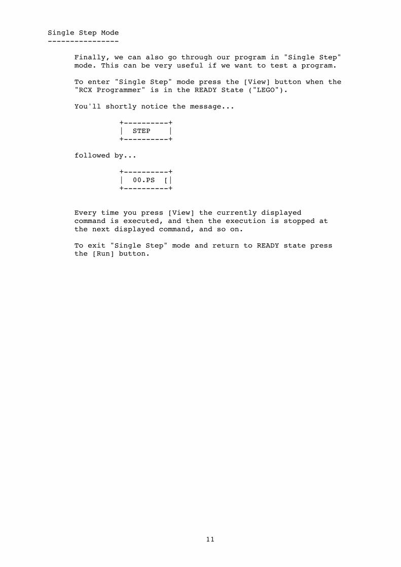
Single Step Mode ---------------- Finally, we can also go through our program in "Single Step" mode. This can be very useful if we want to test a program. To enter "Single Step" mode press the [View] button when the "RCX Programmer" is in the READY State ("LEGO"). You'll shortly notice the message... +----------+ | STEP | +----------+ followed by... +----------+ | 00.PS [| +----------+ Every time you press [View] the currently displayed command is executed, and then the execution is stopped at the next displayed command, and so on. To exit "Single Step" mode and return to READY state press the [Run] button.

12
Deleting a Command ------------------ In "PRGM Mode" you can delete the currently displayed command as follows: Go to the address field, for example address "03": +----------+ | 0'3'.PA [| +----------+ To delete the command at address "03" press and HOLD [Prgm] (this will actually first increment the address to "04" - but don't mind). While still holding [Prgm] press [View] to go back to address "03". Then (while still holding [Prgm]) press [Run]. The current command will be deleted: +----------+ | DEL | +----------+ You'll shortly notice "DEL" and then the next command in the program list will be displayed but now at the address "03" as the previous command has been removed: +----------+ | 0'3'.GO [| +----------+ Note: When you delete a command, all successive commands will move down one address, and the last command will be initialized to "--" (END): addr code addr code 00 PS 00 PS 01 PA 01 PA 02 PS 02 PS DEL -> 03 PA +--> 03 GO 04 GO ---+ 04 -- ^ 05 -- 05 -- | 06 -- 06 -- | .. .. .. .. | FF -- FF -- |
13
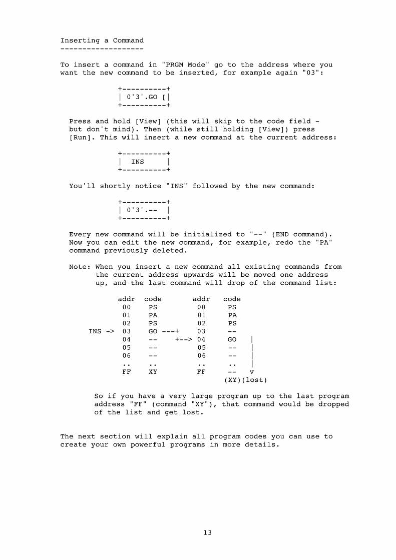
Inserting a Command ------------------- To insert a command in "PRGM Mode" go to the address where you want the new command to be inserted, for example again "03": +----------+ | 0'3'.GO [| +----------+ Press and hold [View] (this will skip to the code field - but don't mind). Then (while still holding [View]) press [Run]. This will insert a new command at the current address: +----------+ | INS | +----------+ You'll shortly notice "INS" followed by the new command: +----------+ | 0'3'.-- | +----------+ Every new command will be initialized to "--" (END command). Now you can edit the new command, for example, redo the "PA" command previously deleted. Note: When you insert a new command all existing commands from the current address upwards will be moved one address up, and the last command will drop of the command list: addr code addr code 00 PS 00 PS 01 PA 01 PA 02 PS 02 PS
INS -> 03 GO ---+ 03 -- 04 -- +--> 04 GO | 05 -- 05 -- | 06 -- 06 -- | .. .. .. .. | FF XY FF -- v (XY)(lost) So if you have a very large program up to the last program address "FF" (command "XY"), that command would be dropped of the list and get lost. The next section will explain all program codes you can use to create your own powerful programs in more details.

14
5. Command Reference ================= This section lists all available "RCX Programmer" command codes, followed by a detailed description of the commands. For easier reading the section is divided into two parts: * Basic Commands (for beginners) * Register Operations (for advanced programming) Command Reference Table Overview ------------------------------------------------------------------ Code: Arguments: Description: ------------------------------------------------------------------ -- stop program execution GO aa continue execution at address <aa> PA a.b.cc pause for the specified time <cc> IN a.b.cc read input port (sensor/battery/key) OU a.b.cc output port (motor control) SS a play a predefined system sound SN aa.bb play a note or music sequence LO aa.bb do while: <aa> loop start addr, <bb> count CS clear screen PC a.b.cc print a character PH aaaa print a hex number (word) PN aaaa print a decimal number (word) PS aa print a predefined string (text message) Pr aaaa print rom/ram data at address <aaaa> JS aa jump/call subroutine rS return from subroutine UL a.b.cc VLL communication Ir a.b.cc IR communication AL aa.bb alarm timer SC a.b system control rO a.b.c.d register operations (see next chapter) Note: All arguments are entered in “hexadecimal” (hex) format, for example: To jump to address 67 enter: GO [ 43 ] ('4' x 16 = 64 + '3' = 67)
Or to enter a pause of 45 seconds: PA [ 0.0.2d ] ('2' x 16 = 32 + '13'(d) = 45)
15
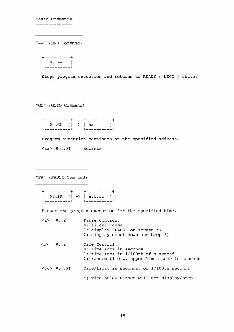
Basic Commands -------------- __________________ "--" (END Command) __________________ +----------+ | 00.-- | +----------+ Stops program execution and returns to READY ("LEGO") state. ___________________ "GO" (GOTO Command) ___________________ +----------+ +----------+ | 00.GO [| -> | aa ]| +----------+ +----------+ Program execution continues at the specified address. <aa> 00..FF address ____________________ "PA" (PAUSE Command) ____________________ +----------+ +----------+ | 00.PA [| -> | a.b.cc ]| +----------+ +----------+ Pauses the program execution for the specified time. <a> 0..2 Pause Control: 0: silent pause 1: display "PAUS" on screen *) 2: display count-down and beep *) <b> 0..2 Time Control: 0: time <cc> in seconds 1: time <cc> in 1/100th of a second 2: random time w. upper limit <cc> in seconds <cc> 00..FF Time/Limit in seconds, or 1/100th seconds *) Time below 0.5sec will not display/beep

16
____________________ "IN" (INPUT Command) ___________________ +----------+ +----------+ | 00.IN [| -> | a.b.cc ]| +----------+ +----------+ Reads the Input Sensors and executes appropriate actions. <a> 0..4 Port: 0: all input ports (1, 2, 3) 1: input port sensor 1 2: input port sensor 2 3: input port sensor 3 4: battery sensor 5: view button 6: prgm button <b> 0..6 Mode: 0: passive (off) 1: active (on) 2: display input data 3: jump if input data below threshold 4: jump if input data true 5: wait until input data below threshold 6: wait until input data true or false <cc> 00..FF Parameter dependent on Mode: Mode: Parameter: ----- --------------------------------- 0..1: 00: other sensor (raw data) 01: touch sensor (touch data) 02: light sensor (light data) 03: temp sensor (raw data) 04: rota sensor (rotation data) 2: 00: display in hexadecimal format 01: display in decimal format 3: 00..FF: sensor data threshold 4: 00..FF: address to jump if true 5: 00..FF: sensor data threshold 6: 00: wait until sensor false (open) 01: wait until sensor true (touched) Note: * Some Sensors need power to operate (active sensors) * Use mode 1 to power on active sensors before use * Set sensor type with mode 0 or 1 for proper reading * Mode 3 will jump to address+2 if sensor data below threshold, or continue with next address otherwise * Mode 4 will jump to specified address if sensor data true, or continue with next address otherwise * Mode 5 will hold execution until below threshold, and then continue with next address
17
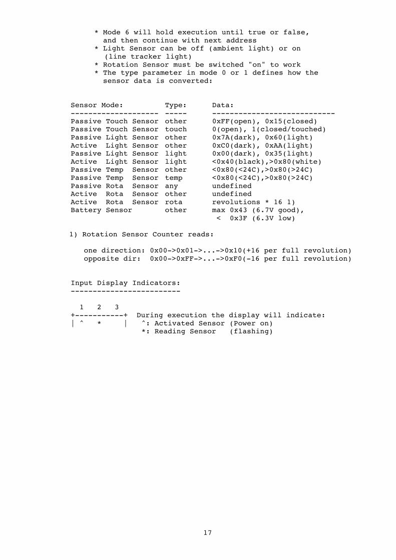
* Mode 6 will hold execution until true or false, and then continue with next address * Light Sensor can be off (ambient light) or on (line tracker light) * Rotation Sensor must be switched "on" to work * The type parameter in mode 0 or 1 defines how the sensor data is converted: Sensor Mode: Type: Data: -------------------- ----- ---------------------------- Passive Touch Sensor other 0xFF(open), 0x15(closed) Passive Touch Sensor touch 0(open), 1(closed/touched) Passive Light Sensor other 0x7A(dark), 0x60(light) Active Light Sensor other 0xC0(dark), 0xAA(light) Passive Light Sensor light 0x00(dark), 0x35(light) Active Light Sensor light <0x40(black),>0x80(white) Passive Temp Sensor other <0x80(<24C),>0x80(>24C) Passive Temp Sensor temp <0x80(<24C),>0x80(>24C) Passive Rota Sensor any undefined Active Rota Sensor other undefined Active Rota Sensor rota revolutions * 16 1) Battery Sensor other max 0x43 (6.7V good),
< 0x3F (6.3V low) 1) Rotation Sensor Counter reads: one direction: 0x00->0x01->...->0x10(+16 per full revolution) opposite dir: 0x00->0xFF->...->0xF0(-16 per full revolution) Input Display Indicators: ------------------------- 1 2 3 +-----------+ During execution the display will indicate: | ^ * | ^: Activated Sensor (Power on) *: Reading Sensor (flashing)

18
_____________________ "OU" (OUTPUT Command) _____________________ +----------+ +----------+ | 00.OU [| -> | a.b.cc ]| +----------+ +----------+ Controls the Output Ports (Motors). <a> 0..6 Port: 0: all output ports (A + B + C) 1: output port A 2: output port B 3: output port C 4: output port A + B 5: output port A + C 6: output port B + C <b> 0..3 Mode 0: off 1: forward 2: reverse 3: brake 4: random
<cc> 00..FF Power: Motor Speed 00: no power ... FF: full power (speed) Note: * In Mode 0 (off) the output is floating * In Mode 3 (brake) the output is closed (shorted) * In Mode 4 the output is random in direction and speed, set <cc> for upper random speed limit Output Display Indicators: -------------------------- | v> <v < >| During execution the display will indicate: +-----------+ v> Output Active/Forward A B C <v Output Active/Reverse < > Output Brake
19
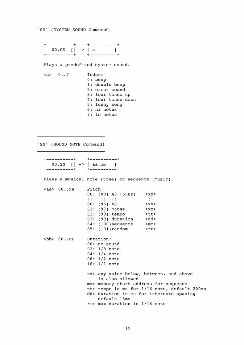
___________________________ "SS" (SYSTEM SOUND Command) ___________________________ +----------+ +----------+ | 00.SS [| -> | a ]| +----------+ +----------+ Plays a predefined system sound. <a> 0..7 Index: 0: beep 1: double beep 2: error sound 3: four tones up 4: four tones down 5: funny song 6: hi notes 7: lo notes _________________________ "SN" (SOUND NOTE Command) _________________________ +----------+ +----------+ | 00.SN [| -> | aa.bb ]| +----------+ +----------+ Plays a musical note (tone) or sequence (music). <aa> 00..98 Pitch: 00: (00) A0 (55Hz) <xx> :: :: :: :: 60: (96) A8 <xx> 61: (97) pause <xx> 62: (98) tempo <tt> 63: (99) duration <dd> 64: (100)sequence <mm> 65: (101)random <rr> <bb> 00..FF Duration: 00: no sound 02: 1/8 note 04: 1/4 note 08: 1/2 note 16: 1/1 note xx: any value below, between, and above is also allowed mm: memory start address for sequence tt: tempo in ms for 1/16 note, default 200ms dd: duration in ms for internote spacing default 15ms rr: max duration in 1/16 note

20
Note: Program execution continues while sound is playing in the background. However, if any sound command follows while a previous sound is still playing, execution is halted until the previous sound ends. Music Sequence: --------------- Pitch "64" allows you to playback a music sequence stored in memory (see Register Operations). <bb> must point to the start memory address (xx) containing the sequence. The sequence in memory must have the following format: Addr: Data: xx+0 pitch: note 0 xx+1 durat: note 0 xx+2 pitch: note 1 xx+3 durat: note 1 .. ... xx+n pitch: FF (end) xx+n+1 durat: 00 (end)

21
___________________ "LO" (LOOP Command) ___________________ +----------+ +----------+ | 00.LO [| -> | aa.bb ]| +----------+ +----------+ Repeates a program section for the specified cycles. <aa> 00..FF Count: (Number of Cycles) <bb> 00..FF Addr: Start address of program section Note: This command is placed at the end of a program section which should be repeated a number of times. The count(er) is decremented every time the program section reaches its end. If the count is down to zero (0) program execution continues with the next address after the loop command, otherwise the loop continues at the specified start address of the program section. Example: Addr: Command: .. .. Start: +-> 08 SS 0 (play a system sound) | 09 PA 0.0.01 (pause 1 sec) | 0A PS 00 (print a message) | 0B PA 0.0.02 (pause 2 sec) End: +-- 0C LO 03.08 (loop 3 times)
0D .. (continue) .. .. ___________________________ "CS" (CLEAR SCREEN Command) __________________________ +----------+ | 00.CS | +----------+ Clears the LCD screen. Any special indicators, such as input port
active, data read, or output port active and direction is also cleared. If you just want to clear the text area of the LCD screen, use the "PS 00" command instead.

22
______________________________ "PC" (PRINT CHARACTER Command) ______________________________ +----------+ +----------+ | 00.PC [| -> | a.b.cc ]| +----------+ +----------+ Prints the specified character or indicator on the screen. <a> 0..8 Type: 0: hex digit 1: decimal digit 2: ascii digit 3: raw digit 4: decimal dot indicator 5: minus indicator 6: IR indicator(s) 7: data transfer indicator(s) 8: data log indicators(s) <b> 0..5 Digit/Indicator Position: Type: Pos: Display: <cc>: ----- ---- -------------- ------------ 0..1: - [ X X ] 00..FF [ 0.0.0.0 0 ] 2..3: x: -> 4|3|2|1 0 00..FF 4: x: -> 4 3 2 - - 00:off/01:on 5: 0: [- ] 00:off/01:on 1: [- (flashing)] 00:off/01:on 6: 0: [v (lower IR)] 00:off/01:on 1: [''(upper IR)] 00:off/01:on 2: V (auto IR)] 00:off/01:on [ '''''(tran)] 00:off/01:on 7: x: -> 43210 00:off/01:on 5: auto trans. 00:off/01:on [(data log) O] 00:off/01:on 8: x: -> 1 /|\ 0 _| x: -> 2 \|/ 3 4: auto log <cc> 00..FF digit code or indicator on/off see above Note:
auto IR Auto animates the IR indicators in the sequence lower, lower+upper, clear auto trans The dots flash from left to right repeating like a progress bar auto log The 4 segments of the circle rotate clockwise

23
________________________ "PH" (PRINT HEX Command) ________________________ +----------+ +----------+ | 00.PH [| -> | aaaa ]| +----------+ +----------+ Prints a hex word on the LCD screen. <aaaa> 0000..FFFF Hex Word: (including leading zeros) ___________________________ "PN" (PRINT NUMBER Command) ___________________________ +----------+ +----------+ | 00.PN [| -> | aaaa ]| +----------+ +----------+ Prints an unsigned decimal number on the LCD screen. <aaaa> 0000..9999 Number: (including leading zeros)

24
___________________________ "PS" (PRINT STRING Command) ___________________________ +----------+ +----------+ | 00.PS [| -> | aa ]| +----------+ +----------+ Prints a predefined text string on the LCD screen. <aa> 00..FF Index: (see table below) <aa> Text: <aa> Text: ---- ----- ---- ----- 00 empty 20 READY 01 LEGO 21 PAUS 02 ON 22 SLEEP 03 OFF 23 BUSY 04 YES 24 INP 05 NO 25 OUT 06 START 26 SENS 07 STOP 27 TOUCH 08 GO 28 LIGHT 09 END 29 DARK 0A ERR 2A ROTA 0B SYS 2B TIME 0C RUN 2C ALARM 0D VIEW 2D PLAY 0E PRGM 2E SOUND 0F STEP 2F TONE 10 ADDR 30 NOTE 11 CLEAR 31 SEND 12 DEL 32 RECV 13 INS 33 SPEED 14 JUMP 34 MOTOR 15 LOOP 35 LEFT 16 ENTER 36 RIGHT 17 PRESS 37 CENTR 18 PUSH 38 HELLO 19 HOLD 39 WORLD 1A HIT 3A TRACK 1B KEY 3B LINE 1C MEM 3C DATA 1D READ 3D TRANS 1E LOAD 3E HAPPY 1F STORE 3F DANY Note: The maximum text string length is 5 characters, as shown in [ HELL O ]. Some ASCII characters may not display well, or are translated to lower case for better readability: WORLD -> UOrLd
25
_________________________________ "PR" (PRINT ROM/RAM Data Command) _________________________________ +----------+ +----------+ | 00.Pr [| -> | aaaa ]| +----------+ +----------+ Prints the data byte at ROM/RAM address <aaaa>. <aaaa> 0000..FFFF Address ______________________________ "JS" (JUMP SUBROUTINE Command) ______________________________ +----------+ +----------+ | 00.JS [| -> | aa ]| +----------+ +----------+ Jumps to a subroutine at the specified address. <aa> 00..FF Address: entry point of subroutine Note: A subroutine is used to execute a code section which is used frequently from many locations in a program. At the end of each subroutine there must be a "RS" (RETURN FROM SUBROUTINE) command. Example: main program: subroutine: addr code addr code 00 .. +-----> 80 XX .. .. | / 81 .. 04 JS 80 -+ | 82 .. .. .. | 83 .. .. .. | 84 RS 17 JS 80 ---+ .. .. +-> 90 XX .. .. | 91 .. 23 JS 90 -----+ 92 .. .. .. 93 RS _____________________________________ "RS" (RETURN FROM SUBROUTINE Command) _____________________________________ +----------+ | 00.rS | +----------+ Returns to the program address from where the subroutine was called by "JS" (JUMP SUBROUTINE) command.
26
________________________________ "VL" (VLL Communication Command) ________________________________ +----------+ +----------+ | 00.UL [| -> | a.b.cc ]| +----------+ +----------+
Allows you to communicate with, or program a Lego device such as: * the "MicroSout" (Lego Mindstorms Droid Developer Kit) * the "CodePilot" (Lego Mindstorms CyberMaster Kit)
using Lego VLL (Visual Light Link) communication. <a> 0..2 VLL Light Port (A:0, B:1, C:2 Motor Ports) <b> 0..1 Control: 0: Send VLL code 1: Receive VLL code (not implemented) <cc> 00..FF VLL code (see table below) Note: Attach a Light Sensor to one of the OUTPUT Ports A, B, or C (NOT Port 1,2, or 3). Hold the Light Sensor in front of the MicroScout’s or CodePilot’s LED, then Execute the command (Run). The light sensor LED will flash approx. for one second and send out the VLL Bar Code. The MicroScout must be in “P” program mode. The CodePilot must be in “Rec” mode. "Direct" codes will be executed immediately after the VLL code is sent. All other codes are used to program the device. MicroScout VLL Codes: ---------------------------------------------------------------- Code: Action: Code: Action: ---------------------------------------------------------------- 00 Forward (direct) 18 Beep 1 01 Reverse (direct) 19 Beep 2 04 Beep 1 (direct) 1A Beep 3 05 Beep 2 (direct) 1B Beep 4 06 Beep 3 (direct) 1C Beep 5 07 Beep 4 (direct) 1D Wait for Light 08 Beep 5 (direct) 1E Seek Light 0A Stop (direct) 1F Code (Game) 10 Forward 0.5 sec 20 Keep Alive 11 Forward 1.0 sec 21 Run 12 Forward 2.0 sec 22 Delete Program 13 Forward 5.0 sec 46 Next 14 Reverse 0.5 sec 47 Reset 15 Reverse 1.0 sec 16 Reverse 2.0 sec 17 Reverse 5.0 sec
27
CodePilot VLL Codes: ---------------------------------------------------------------- Code: Action: Code: Action: ---------------------------------------------------------------- 00 Forward 6A Play Tone G 01 Reverse 6B Play Tone G# 04 Sound VALVE 6C Play Tone A 05 Sound Helicopter 6D Play Tone A# 06 Sound Truck 6E Play Tone B 07 Sound Robot 6F Play Tone C hi 08 Sound Machine 70 Number 0 0A Mute 71 Number 1 10 STOP 72 Number 2 11 Motor no Sound 73 Number 3 12 Prg Truck 74 Number 4 13 Prg Wheel Driver 75 Number 5 14 Prg Crash Buggy 76 Number 6 15 Prg Robot 77 Number 7 61 Touch in 78 Number 8 62 Touch out 79 Number 9 63 Play Tone C 7A Decimal Dot 64 Play Tone C# 7B Random 65 Play Tone D 7C Speed low 66 Play Tone D# 7D Speed medium 67 Play Tone E 7E Speed hi 68 Play Tone F 7F Tacho 69 Play Tone F#

28
_______________________________ "IR" (IR Communication Command) _______________________________ +----------+ +----------+ | 00.Ir [| -> | a.b.cc ]| +----------+ +----------+
Infrared Communication Port options include: * Select IR Protocol (LEGO, USER or FURBY) * Receive/Display/Send “LEGO Mindstorms Messages” * React to “Lego IR Remote Button Commands” * Record/Display/Send/React on USER/FURBY defined IR codes
<a> Control: <b>: <cc>: 0: Init 0: IR OFF -- 1: IR LEGO -- 2: IR USER <proto> 3: IR FURBY -- <proto> bit8: (X0000000) Don’t Care bit7: (0X000000) Data Bits: 0: 8 bits (LEGO) 1: 7 bits bit6: (00X00000) Parity Bit: 0: even 1: odd (LEGO) bit5: (000X0000) Parity: 0: off 1: on (LEGO) bit4: (0000X000) Stop Bits: 0: 1 stop bit (LEGO) 1: 2 stop bits bit3..0:(00000XXX) Baud Rate: 000 2400 (LEGO) 001 4800 010 9600 011 19200 100 38400 1: Display <b>: <cc>: 0: Message/Data 0:hex, 1:decimal 1: Remote Control -- 2: USER Codes 00..0F (mem) 3: FURBY Message 0:hex, 1:decimal 2: Send <b>: <cc>: 0: Message/Data 00..FF (byte) 1: USER Codes 00..0F (mem) 2: FURBY Message 00..0F (msg) 3: Remote <b>: <cc>: 0: Off -- 1: On -- 2: Program -- 3: Record USER 00..0F (mem) 4: Exec USER --

29
4: Program <b>: <cc>: 0..F (button) 00..FF (addr) 5: Exec <b>: <cc>: 0..F (mem) 00..FF (addr) 8..F: mem[X] <b>: <cc>: 0..F (step) 00..FF (code)
Init: Before you can use IR commands, you need to setup the InfraRed Port of the “RCX Brick”. You can either select the native “LEGO” protocol, a “USER” defined protocol, or the FURBY protocol. The “LEGO” serial protocol uses 1 start bit, 8 data bits, odd parity, and 1 stop bit at a baudrate of 2400bps (bits per second). The “USER” setting allows you to choose a different serial protocol to adapt for other IR devices, such as TV/Radio/etc. remote control units.
Display: Message/Data:
Depending on the selected protocol “LEGO” or “USER”, the display command will automatically display either the received “LEGO Mindstorms Broadcast Messages” (one byte per message), or the raw data byte stream. “LEGO Mindstroms Broadcast Message” (HEX):
AA FF 00 F7 08 MSG ~MSG CHK ~CHK
|header| |cdm| |msg | |chksum|
If you select the “LEGO” protocol, only the “msg” byte is displayed. If you select the “USER” protocol with the correct LEGO serial settings, you can see all received bytes of the message protocol starting with “AA”. Remote Control: You can also display received “LEGO Mindstorms Remote Control” button status bits. The IR protocol must be set “IR LEGO”. The button status bits are explained on the next page. “LEGO Mindstorms Remote Control” Button Status Message:
AA FF 00 D2 2D MSB ~MSB LSB ~LSB CHK ~CHK |header| |cmd| |msb| |lsb| |chksum|

30
LEGO Remote Control Button Status: MSB LSB: Auto: ---------------------------------- -------- ----- 0: Message 1 00000000 00000001 0x0001 1: Message 2 00000000 00000010 0x0002 2: Message 3 00000000 00000100 0x0004 3: A Forward 00000000 00001000 0x0008 X 4: B Forward 00000000 00010000 0x0010 X 5: C Forward 00000000 00100000 0x0020 X 6: A Reverse 00000000 01000000 0x0040 X 7: B Reverse 00000000 10000000 0x0080 X 8: C Reverse 00000001 00000000 0x0100 X 9: Program 1 00000010 00000000 0x0200 A: Program 2 00000100 00000000 0x0400 B: Program 3 00001000 00000000 0x0800 C: Program 4 00010000 00000000 0x1000 D: Program 5 00100000 00000000 0x2000 E: Stop 01000000 00000000 0x4000 F: Beep 10000000 00000000 0x8000 X -: All released 00000000 00000000 0x0000
USER Codes: Displays previously recorded USER codes (see also “Remote Record USER” codes for more details).
FURBY Messages: Although FURBY uses a special IR protocol, this option tries to decode FURBY messages. It may or may not work in your particular situation (experimental only): 00: Hello 0 04: Party 1 08: Sneeze 0C: Yawn 01: Hello 1 05: Party 2 09: Burp 0D: Hide 02: Hello 2 06: Dance 1 0A: Joke 0E: Sleepy 03: Hello 3 07: Dance 2 0B: Sing 0F: Sleep Send: Message/Data:
Sends a single “LEGO Mindstorms Broadcast Message” byte if the IR protocol is set to “IR LEGO”, or a raw USER data byte if set to “IR USER”. USER Codes: Sends previously recorded USER codes (see also “Remote Record USER” codes for more details).
FURBY Message: Sends a FURBY message (00..0F: see above)
31
Remote: Allows you to activate (on), or deactivate (off)
“LEGO Remote Control” actions. If activated, and the “RCX Brick” receives any “LEGO Remote Control” messages, it will automatically execute appropriate remote control button actions marked with “auto” (see previous table).
The “RCX Brick” executes received remote commands either in “READY”, or in “EXEC” mode. Program: Allows you to check for “LEGO Remote Control” commands and execute your own actions in your program (for more details see “Program”). Record USER: Lets you record IR messages sent by other IR devices, such as TV/VCR remote control units, if they use an IR protocol, which you can adapt by using the “Init IR USER” command. There are 16 USER memories available which can hold up to 16 bytes per code or command. To record a USER code/command, run this command while pointing with your IR device towards the “RCX Brick” IR Port, and pressing a remote button. Exec USER: Allows you to execute your own actions, if the “RCX Brick” receives a previously recorded USER code or command (for more details see “Exec”). Program: If the “LEGO Remote Control” is activated, the “RCX Brick” executes some remote commands automatically as explained above. The “Program” command allows you to override the auto actions by your own actions, or define actions for which there are no auto actions. For example, if you want to override the “Beep” remote button command, put this command before your new “Beep” program code as follows: 00.Ir [ 4.F.20 ] (point to your “beep” program) 01.Ir [ 0.1.00 ] (initialize “IR LEGO” protocol) 02.Ir [ 3.1.00 ] (activate LEGO remote control) 03.Ir [ 3.2.00 ] (check remote command and jump) 04.GO [ 03 ] (check for new remote command) .. 20.SS [ 3 ] (your new “beep” program code) 21.GO [ 03 ] (check for new remote command)
Whenever you press the “Beep” button on the “LEGO Remote Control” unit, the program will jump to address “20”.
32
Exec: You can also define your own actions for any IR USER
code/command received which matches one of the previously recorded USER codes/commands stored in one of the 16 USER memories. This is done the same way as described above for the “LEGO Remote Control”.
mem[X]: Edit IR USER memory
If you have difficulties recording a IR USER command, you can enter the sequence of bytes used to define the code or command for a specific remote device manually as follows. For example, if we want to enter the sequence “22 37 01 FF” and store it in USER memory “A”: 00.Ir [ A.0.22 ] 01.Ir [ A.1.37 ] 01.Ir [ A.2.01 ] 01.Ir [ A.3.FF ]
Manual editing is only possible with USER memories “8..F”. __________________________ "AL" (ALARM TIMER Command) __________________________ +----------+ +----------+ | 00.AL [| -> | aa.bb ]| +----------+ +----------+ Executes the user program if system time reaches the alarm time <aa> hours <bb> minutes. <aa> 00..FF time in hours <bb> 00..59 time in minutes Note: You need to execute this command to set the alarm. After alarm is set, alarm execution will only work when in READY "LEGO" mode. Be sure to replace the AL command in your user program to avoid alarm loop. Once the alarm has been activated a circling counter log symbol is shown on the right side of the screen: +-------+ | LEGO!°| ° circling alarm indicator +-------+

33
_____________________________ "SC" (SYSTEM CONTROL Command) _____________________________ +----------+ +----------+ | 00.SC [| -> | a.b ]| +----------+ +----------+ Controls "RCX Brick" system parameters. System Control Table ------------------------------------------------------------- <a> (Ctrl) <b> (Mode) Description (default setting) ------------------------------------------------------------- 0 power 0 off switch power off immediate 1..F auto power off after x min (5min) 1 battery 0 off battery status off 1 on battery status on (default) 2 button 0 off button beep off (default) 1 on button beep on 3 error 0 off no error messages 1 on display error messages (default) 4 systime 0..F sec display system time for x sec F reset - -- CAUTION: this will execute a system reset and restore to factory defaults (data and firmware is cleared)! Note: You need to execute (Run) the command to activate the settings. Once the RCX is powered or switched off it cannot be activated (switched on) anymore by a command. You have to manually press the [On-Off] button to switch it on again. System Time is reset to “00.00” (hours.minutes) after power-up.

34
6. Register Operations =================== _________________________________ "RO" (REGISTER OPERATION Command) _________________________________ +----------+ +----------+ | 00.RO [| -> | a.b.c.d ]| +----------+ +----------+ Register Operations allow you to use 16 internal one byte
registers and a 256 byte memory area for creating advanced user programs.
<a> 0..C Operation Code (opc): <b> 0..F Argument 1 <c> 0..F Argument 2 <d> 0..F Argument 3 Note: <a..c> register number (uses data in register “r”) <h> upper 4 bits (for data, addresses, etc) <l> lower 4 bits (for data, addresses, etc) -------------------------------------------------------------- Register Operation Table -------------------------------------------------------------- <a> (opc): <b>: <c>: <d>: Description: -------------------------------------------------------------- 0 LDD <a> <h> <l> load direct data 1 LDA <a> <h> <l> load from memory address 2 LDI <a> <b> <i> load from memory indirect 3 LDR <a> <h> <l> load from random generator 4 STA <a> <h> <l> store to memory address 5 STI <a> <b> <i> store to memory indirect 6 DSP <x> <y> <z> display data 7 INP <a> <b> <c> input data 8 OUT <a> <b> <c> output data 9 BIT <a> <o> <n> bit operation A BYT <a> <b> <o> byte operation B BRA <x> <h> <l> branch condition code C JSR <a> <b> <c> jump subroutine D VLL <a> <b> <c> VLL communication E IRC <x> <a> <b> IR communication
All register operations will now be described in more details.
35
______________________ LDD - Load Direct Data 0 <a> <h> <l> ______________________ Loads the data byte <h> <l> into register <a>. <a>: 0..F register number <h>: 0..F upper 4 data bits <l>: 0..F lower 4 data bits carry bit: always cleared zero bit: set if zero, cleared otherwise ___________________________________ LDA - Load Data from Memory Address 1 <a> <h> <l> ___________________________________ Loads the data byte stored at memory address <h> <l> in register <a>. <a>: 0..F register number <h>: 0..F upper 4 memory address bits <l>: 0..F lower 4 memory address bits carry bit: always cleared zero bit: set if zero, cleared otherwise ________________________ LDI - Load Data Indirect 2 <a> <b> <i> ________________________
Loads the data byte stored at the memory address pointed to by register <b> in register <a>.
<a>: 0..F register number <b>: 0..F register number (address pointer) <i>: 0..2 auto index (after load) 0: off 1: increments address pointer by one 2: decrements address pointer by one carry bit: always cleared zero bit: set if zero, cleared otherwise

36
________________________ LDR - Load Random Number 3 <a> <h> <l> ________________________ Loads a random number in register <a>. Set a random seed number <h> <l> for the random generator. <a>: 0..F register number <h>: 0..F seed number upper 4 bits <l>: 0..F seed number lower 4 bits carry bit: always cleared zero bit: set if zero, cleared otherwise Note: If the seed number is zero "00" the register <a> is loaded with a random number. Otherwise the seed number <h> <l> is used to initialize the random generator. Set a seed number at the beginning of your program, before loading random numbers. __________________________________ STA - Store Data at Memory Address 4 <a> <h> <l> __________________________________ Stores the data byte in register <a> at memory address <h> <l>. <a>: 0..F register number <h>: 0..F upper 4 memory address bits <l>: 0..F lower 4 memory address bits carry bit: always cleared zero bit: set if zero, cleared otherwise _________________________ STI - Store Data Indirect 5 <a> <b> <i> _________________________ Stores the data byte in register <a> at the memory address pointed to by register <b>. <a>: 0..F register number <b>: 0..F register number (address pointer) <i>: 0..2 auto index (after load) 0: off 1: increments address pointer by one 2: decrements address pointer by one carry bit: always cleared zero bit: set if zero, cleared otherwise

37
__________________ DSP - Display Data 6 <x> <y> <z> __________________ Displays register and user memory data on the LCD screen. <x>: display: <y>: <z>: 0: data in register a fmt 1: data in memory addr-> <a> fmt 2: data at rom/ram addr-> <a>, <a+1> fmt 3: system message <a> - 4: memory string addr-> <a> - a: direct register number <a>: indirect register addressing fmt: format: 0: display byte in hex 1: display byte in decimal 2: display word in hex 3: display word in decimal carry bit: unchanged zero bit: unchanged ________________ INP - Input Data 7 <a> <b> <c> ________________ Calls the IN (INPUT) function controlled by registers (see Basic Commands in Chapter Command Reference). <a>: 0..F register number <b>: 0..F register number <c>: 0..F register number carry bit: always cleared zero bit: set if zero, cleared otherwise Note: The result of any input data read is returned in register number "F".
38
_________________ OUT - Output Data 8 <a> <b> <c> _________________ Calls the OU (OUTPUT) function controlled by registers (see Basic Commands in Chapter Command Reference). <a>: 0..F register number <b>: 0..F register number <c>: 0..F register number carry bit: unchanged zero bit: unchanged ____________________ BIT - Bit Operations 9 <a> <o> <n> ____________________ Executes single register operations in register <a>. <a>: 0..F register number <o>: 0..F operation: 0: CLR - clear register 1: INC - increment register by one 2: DEC - decrement register by one 3: INV - inverse bits in register 4: SHL - shift bits left <n> times 5: SHR - shift bits right <n> times <n>: 0..8 bit shift count carry bit: set if over/under run (INC/DEC), or shift bit in carry zero bit: set if zero, cleared otherwise
39
_____________________ BYT - Byte Operations A <a> <b> <o> _____________________ Executes byte operations with registers <a> and <b>. Result is returned in register <a>. <a>: 0..F register number <b>: 0..F register number <o>: 0..8 operation: 0: CPY: <a> -> <b> (copy) carry bit: cleared zero bit: set if zero 1: ADD: <a> += <b> carry bit: set if overflow zero bit: set if zero 2: SUB: <a> -= <b> carry bit: set if underflow zero bit: set if zero 3: MUL: <a> *= <b> carry bit: set if overflow zero bit: set if zero 4: DIV: <a> /= <b> carry bit: set if <0, or divide by zero! zero bit: set if zero, or divide by zero! 5: AND: <a> &= <b> carry bit: unchanged zero bit: set if zero 6: OR: <ra> |= <rb> carry bit: unchanged zero bit: set if zero 7: EOR: <a> ^= <b> carry bit: unchanged zero bit: set if zero 8: CMP: <a> <?> <b> (compare) carry bit: set if <a> < <b> zero bit: set if <a> == <b>
40
___________________________ BRA - Branch Condition Code B <x> <h> <l> ___________________________ Evaluates the result of a register operation by testing the carry and zero bits, and branches to address <h> <l> if condition code <x> is true. <x>: 0..7 condition code: 0: BEQ/BZS zero or equal (zero set) 1: BNE/BZC not equal (zero clear) 2: BCC carry clear 3: BCS carry set (over/under-flow) 4: BHI higher (carry clr / zero clr) 5: BLO lower (carry set / zero clr) 6: BEH equal/higher (carry clr||zero set) 7: BEL equal/lower (carry set||zero set) 8: BRA always (goto) <h>: 0..F branch address upper 4-bits <l>: 0..F branch address lower 4-bits carry bit: unchanged zero bit: unchanged _____________________ JSR - Jump Subroutine C <ra> <b> <c> _____________________ Calls a subroutine located at address pointed to by register <a>. The register <b> and <c> can be used as pointers to pass variables to the calling routine. <a>: 0..F register number (subroutine addr pointer) <b>: 0..F register number for passing variables <c>: 0..F register number for passing variables Note: Don't forget to end the subroutine program code by a "rS" (Return from Subroutine) command (see Basic Commands in chapter Command Reference).
41
___________________ VLL - Communication D <a> <b> <c> ___________________ Sends a byte using the basic VLL (Visual Light Link) communication
command (see “Basic Command Reference”). <a>: 0..F register number <b>: 0..F register number <c>: 0..F register number
______________________ IRC – IR Communication E <x> <a> <b> ______________________ Receive or send data using the “RCX Brick” IR Port. <x>: 0..1 Control: 0: receive data 1: send data
<a>: 0..F Register <a>: number of bytes received (max 16) number of bytes to send (max 16)
<b>: 0..F Register <b>: memory addr (start of data buffer) Note: You must setup the IR communication using the Basic “IR” command (see “Basic Command Reference”), before you can receive or send any data bytes. Receive data will return number of bytes read in Register <a>. The received data is stored in memory area starting at addr pointed to by register <b>. Reserve at least 16 bytes in the memory for the buffer. To send data you must first fill a memory area (buffer) with the data, then load register <b> with the start memory addr, and register <a> with the number of bytes to be sent.
42
7. Programming Examples ==================== Example 1: (Motor A) ---------- Drive forward for 3 sec, stop, pause for 2 sec, then drive backward for 1 sec, full stop:
00.OU [ 1.1.FF ] Motor A forward full power 01.PA [ 0.0.03 ] for 3 seconds 02.OU [ 1.3.00 ] Motor A stop (brake) 03.PA [ 0.0.02 ] Pause 2 seconds 04.OU [ 1.2.FF ] Motor A backward full power 05.PA [ 0.0.01 ] for 1 second 06.OU [ 1.3.00 ] Motor A stop (brake) 07.PA [ 0.0.01 ] wait for full stop 08.OU [ 1.0.00 ] Motor A off
Example 2: (Race) ---------- After pressing Touch Sensor 1 countdown and start race with motor A and C at full power for 5 seconds, then wait for next touch: 00.IN [ 0.1.01 ] Define Touch Sensor on Port 1 01.IN [ 1.6.01 ] Wait until Touch Sensor 1 true 02.PA [ 2.0.04 ] Countdown and start 03.OU [ 5.1.FF ] Motor A+C forward full power 04.PA [ 0.0.05 ] for 5 seconds 05.OU [ 5.3.00 ] Motor A+C stop (brake) 06.PA [ 0.0.01 ] wait for full stop 07.OU [ 5.0.00 ] Motor A+C off 08.GO [ 01 ] Wait for next touch Example 3: (Random Music) ---------- Play some random music. 00.SN [ 65.02 ] Sound a random tone at max ¼ note length 01.GO [ 00 ] repeat to generate random music Example 4: (Light Alarm) ---------- Alarm if someone lights up a dark room (Light Sensor at Port 1): 00.IN [ 1.0.02 ] Setup passive Light Sensor at Port 1 01.IN [ 1.5.80 ] Wait until some light detected 02.SS [ 0 ] Beep 03.IN [ 1.3.80 ] Still some light? 04.GO [ 01 ] no: wait again until light detected 05.GO [ 02 ] yes: continue with beep