leh984e programmable logic controller spb
TRANSCRIPT

LEH984e
Programmable Logic ControllerIntegrated ControllersIntegrated Controllers SeriesSeries
2 3
Features .................................................................. 3SPB Lineups ............................................................ 4System Configurations ............................................ 6Specifications .......................................................... 9External Connection Diagrams .............................. 14Control Functions .................................................. 15Programming Languages ...................................... 16Online Adapters ..................................................... 20Dimensions ............................................................ 21Ordering Informations ............................................ 22
C o n t e n t s
Online program edit functionAllows program modification without interrupting machine op-eration.
International standards conformityAll SPB models conform to the UL/cUL standards as well as the CE mark standard.
Two analog timers Two analog timers are built in for convenient fine-tuning and testing.
Communication & NetworkingCommunication adapters are available for RS-232C, RS-485, and simplified personal computer link connections.
POD direct connectionThe SPB can be connected to the POD via the loader port. No special communication unit is required.
Diversified functions for expanding applications• Internal high-speed counter function• Interrupting function• Pulse train output function• Pulse catch function• Constant scan setting• Pulse width modulation function
Adapted to analog controlMulti-range (voltage / current) adapted. 3 types of analog unit with detachable terminal blocks are added to the lineup.Capable of analog control, such as temperature control by PID instruction.
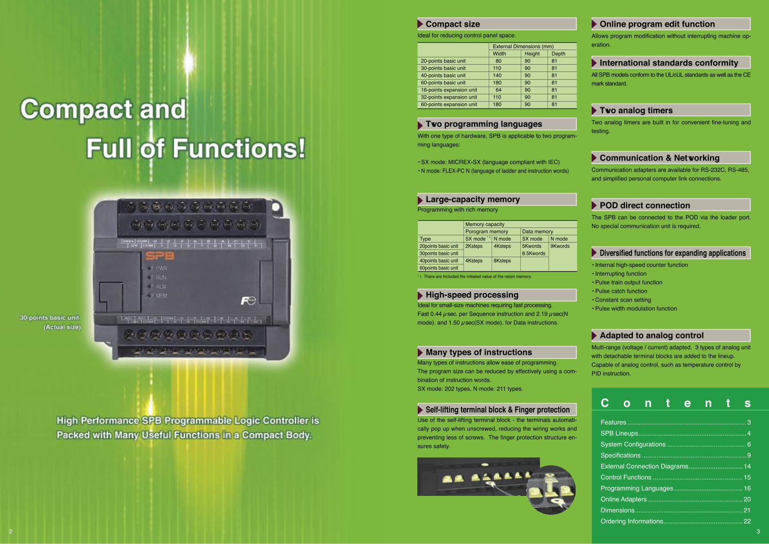
Compact sizeIdeal for reducing control panel space.
Two programming languages With one type of hardware, SPB is applicable to two program-ming languages:
• SX mode: MICREX-SX (language compliant with IEC)• N mode: FLEX-PC N (language of ladder and instruction words)
Large-capacity memory Programming with rich memory
High-speed processing Ideal for small-size machines requiring fast processing. Fast 0.44 µsec. per Sequence instruction and 2.19 µsec(N mode). and 1.50 µsec(SX mode). for Data instructions.
Many types of instructions Many types of instructions allow ease of programming.The program size can be reduced by effectively using a com-bination of instruction words.SX mode: 202 types, N mode: 211 types.
Self-lifting terminal block & Finger protectionUse of the self-lifting terminal block - the terminals automati-cally pop up when unscrewed, reducing the wiring works and preventing less of screws. The finger protection structure en-sures safety.
Memory capacity Porogram memorySX mode * 12Ksteps
4Ksteps
Data memorySX mode 5Kwords8.5Kwords
N mode 9Kwords
N mode 4Ksteps
8Ksteps
Type20points basic unit30points basic unit40points basic unit60points basic unit
* 1 There are Included the initiated value of the retain memory.
20-points basic unit30-points basic unit40-points basic unit60-points basic unit16-points expansion unit32-points expansion unit60-points expansion unit
Depth81818181818181
External Dimensions (mm)Width 80110140180 64110180
Height90909090909090

20-points Basic Unit: NW0P20 - Power voltage: 100-200V AC, 24V DC Input: 12 points, Output: 8 points Relay output, Transistor output Stand alone unit no expansion
30-points Basic Unit: NW0P30 - Power voltage: 100-200V AC, 24V DCInput: 16 points, Output: 14 pointsRelay output, Transistor outputConnectable up to five expansion units
SPB Lineups
4
40-points Basic Unit: NW0P40 - Power voltage: 100-200V AC, 24V DC Input: 24 points, Output: 16 points Relay output, Transistor output Connectable up to five expansion units Calendar function (year, month, day, hour, minute, second, day of week) (different type)
0
020406080100120
20
40
60
80
100
120
Dimensions (mm)
20
0
020406080100120
20
40
60
80
100
120
Dimensions (mm)
30
0
020406080140160180 100120
20
40
60
80
100
120
Dimensions (mm)
40
0
020406080140160180 100120
20
40
60
80
100
120
Dimensions (mm)
60
Basic Unit
60-points Basic Unit: NW0P60 - Power voltage: 100-200V AC, 24V DCInput: 36 points, Output: 24 pointsRelay output, Transistor outputConnectable up to five expansion units Calendar function (year, month, day, hour, minute, second, day of week) (different type)

●Digital I/O Unit ●Analog Unit
Expansion Unit
5
OptionCommunication Adapter
16-points I/O Expansion Unit: NW0E16 -3Input: 8 points, Output: 8 pointsRelay output, Transistor output
16-points Input Expansion Unit: NW0E16XInput: 16 points
16-points Output Expansion Unit: NW0E16 -0Relay output, Transistor output
32-points I/O Expansion Unit: NW0E32 -3Input: 16 points, Output: 16 pointsRelay output, Transistor output
60-points I/O Expansion Unit: NW0E60R-31Power voltage: 100-200V ACInput: 32 points, Relay output: 28 points
Analog Input Unit: NW0AX04-MRMulti-range input: 4ch
Analog Output Unit: NW0AY04-MRMulti-range output: 4ch
Analog I/O Unit: NW0AW03-MRMulti-range input: 2chMulti-range output: 1ch
Thermocouple Input Module: NW0AX04-TCInput: 4ch
Resistance Bulb Input Module: NW0AX04-PTInput: 4ch
RS-232C Adapter: NW0LA-RS2General-purpose communication mode: RS-232C 1ch
RS-485 Adapter: NW0LA-RS4General-purpose communication mode: RS-485Simplified CPU link mode1ch
Memory Card: NW8PMF-8Flash ROM for 40/60-points basic unit

6
For the SPB, the number of I/O points can be increased up to 360 by adding digital I/O units to the basic unit. Up to five digital I/O units can be added.
Expansion Digital I/O System
●Basic Unit + Digital I/O Unit
System with a combination of 16- and 32-point digital I/O unitsThe system with no 60-point digital I/O units allows addition of a maximum of three units, or 64 digital I/O points.
System with 60-point digital I/O unitsA maximum of five 60-point digital I/O units, or 300 digital I/O points can be added.
System with a combination of 16- 32- and 60-point digital I/O units
* The basic unit and 60-point digital I/O unit require a power supply. The 16-/32-point digital I/O units are supplied the power from the basic unit and 60-point digital I/O unit as indicated with an arrow ( ). One basic unit or one 60-point digital I/O unit can supply power to a maximum of three expansion units (64 or fewer I/O points).
60 points digital I/O unitBasic unit
Basic unit
Basic unit
System Configurations
Maximum five units (system including 60-point digital I/O unit)
Maximum five units (system with 60-point digital I/O units)
Maximum three units (up to 64 I/O points)
Max. digital I/O points 20 points 330 points340 points 360 points
NW0P20 -3NW0P30 -3NW0P40 -3NW0P60 -3
I/O Points20 points30 points40 points60 points
360 points (60+60+60+60+60+60)
Maximum three units (up to 64 I/O points)
Maximum three units (up to 64 I/O points)
Basic unit

7
Basic unit and maximum number of expansion units• The 20-point basic unit does not allow connecting expansion units.• The maximum number of expansion units varies depend ing on the basic unit and digital I/O unit versions.• Note that some basic unit versions do not allow connecting analog units. See the table given on the right for details.
16-points expansion
16-points expansion
16-points expansion
Basic unit
For the SPB, up to three analog units can be added to the basic unit.By doing so, the number of analog I/O points can be increased up to 12.
Expansion Analog System
●System expanded only with analog units
System without 60-point digital I/O unitsAlso when the basic unit is used in combination with 16-/32-point digital I/O units and/or analog units, a maximum of three units can be added.
●System expanded with a combination of digital I/O unit and analog unit
Analogunit
Basic unit
32-points expansion
Analogunit
Analogunit
Analogunit
Basic unit
Analogunit
Analogunit
Basic unit
32-points expansion
32-points expansion
System with 60-point digital I/O unitsWhen the basic unit is used in combination with 60-point digital I/O units and/or analog units, a maximum of five units can be added (up to three analog units).
Points for system expansionTo each of the basic unit and 60-point digital I/O unit, a maximum of three units can be added (64 or fewer I/O points + analog unit). Note that the maximum number of expansion units is 5.
Analogunit
60-points expansion
Connect this unit at a position where power can be supplied from the 60-point digital I/O unit.
Maximum 3 units (12 analog I/O points )
Maximum 3 units (64 or less digital I/O points + analog unit)
Maximum 3 units (64 or less digital I/O points + analog unit) Maximum 3 units (64 or less digital I/O points + analog unit)
Maximum 5 units
Up to three expansion units (64 or less digital I/O points + analog unit)
60-points expansion
Analogunit
Max. number of connectable expansion units
Versions of basic unit
Older than version 10.0710.07 to 20.10Version 20.11 or later
Digital I/O unitOlder than version 102 units2 units2 units
Digital I/O unitVersion 10 or later2 units3 units5 units
Connection of analog unit
ImpossiblePossiblePossible

Basic unitUG30 series
1) RS-485 mode
1) Loader port connectionThe programmable operation display (POD) can directly be connected to the loader port.
Basic unit
2) Simplified CPU link mode
Basic unitBasic unitBasic unit
Basic unit
RS-232C Adapter
Dedicated cableType: UG200C-N0
Item SpecificationElectrical specifications RS-485Communication specifications NP link microConnection form BusTransmission rate 125kbps max.Transmission distance 500m max.Number of units connected 16 units max. Data amount 32 words/station max.
UG30 series
• Personal computer• Printer• Barcode reader• Other devices for RS-232C
Basic unit
RS-485 Adapter• Personal computer• Barcode reader• Other devices for RS-485
RS-485 Adapter
2) General-purpose communication connectionConnection through the RS-232C/RS-485 adapter is possible.
Communication adapter
* When connecting with the NB series, the transmission rate is limited to 19.2 kbps and the data amount to 8 words/station.
●System based on RS-232C Adapter: NW0LA-RS2
●System based on RS-485 Adapter: NW0LA-RS4
●POD Connections
Personalcomputer
Handy Loader
Program Loader
Item SpecificationElectrical specifications RS-232CCommunication specifications Half-duplex transmissionConnection form 1:1Transmission rate 38.4kbps max.Transmission distance 15m max.User interface Nonsequenced transmission/ command set type transmission
System Configurations
Communication Systems
8
Item SpecificationElectrical specifications RS-485Communication specifications Half-duplex transmissionConnection form 1:31 (max.)Transmission rate 38.4kbps max.Transmission distance 1km max.User interface Nonsequenced transmission/ command set type transmission

9
Specifications
Item SpecificationCalculation control Stored program repeated calculation methodI/O control method Batch refresh method/Direct methodProgram language Ladder, mnemonicProgram capacity Basic unit 20/30 points : 4K steps (flash memory built in) Basic unit 40/60 points : 8K steps (flash memory built in)No. of Sequence instruction 45 typesinstructions Applied instruction 166 typesInstruction processing speed Basic instruction 0.44µs or more Applied instruction 2.19µs or moreI/O relay X,Y 1024 pointsInternal relay M 1024 pointsExpanded internal relay M 3072 pointsLatch relay L 1024 pointsExpanded latch relay L 3072 pointsSpecial relay M 512 pointsTimer (10 ms base) T 384 points (T000 to T17F) (1 ms base) T 128 points (T180 to T1FF)Counter (increment) C 256 pointsRegister Data register D 8192 words Special register D 256 points File register R Uses the program area depending upon the settingPointer For branching P 256 points For interrupt I 10 pointsInput filter time Variable (No filter, 3ms/3ms (default), 10ms/10ms)High-speed counter Single-phase, 100kHz, 2points (unsigned 16-bit) or Two-phase, 50kHz, 1point (signed 32-bit)Pulse output 1 to 100kHz, 2points (transistor output type basic unit only)Self-diagnostic function Memory check, watchdog timer, etc.Memory backup Program (including file registers), parameters • Built-in RAM + capacitor and built-in flash (20/30-points unit) • Built-in RAM + battery and built-in flash (40/60-points unit) Data memory (power failure retaining area) • Built-in RAM + capacitor (20/30-points unit) • Built-in RAM + battery (40/60-points unit) Backup time of the memory • Built-in RAM + capacitor backup time: About 2 weeks (at 25˚C) • Built-in RAM + battery backup time: About 5 years (at 25˚C) • Number of updates of built-in flash: About 100,000 timesCalendar Accuracy ± 27 seconds/month (at 25˚C) (Calendar function adapted type only)
●General Specifications Item SpecificationPhysical Operating ambient 0 to +55˚Cenvironment temperature Storage (transport) –25 to +70˚C temperature Relative humidity 20 to 95% RH no condensation Pollution level Level 2 (IEC61131-2) Corrosive gas Free from corrosive gases, not stained with organic solvents Altitude/Atm. 2000m or less above sea level (Transport condition : 70kPa or more)Mechanical Vibration Half amplitude 0.15mm, Constant acceleration operating resistance 19.6m/s2, 2 hours in each direction, 6 hours in totalcondition Impact resistance Peak acceleration 147m/s2 (IEC conformance), 3 times in each directionElectrical Electrostatic discharge ± 6 kV: contact discharge, ± 8 kV: aerial discharge operating resistance (class 3)condition Radiation resistance 10V/m (80 to 1,000MHz) Noise immunity Noise simulator method, rising 1ns, Pulse width 1µs, 1.5kVGrounding method Type D grounding (ground resistance 100Ω)Structure Panel-mounted type IP30Installation method Installation direction: Vertical Fixing method: Direct installation (M4 screws) or installation with JIS/IEC (35mm wide) support railCooling method Ambient air-cooled
●Performance Specifications (N mode)
●Performance Specifications (SX mode)
Basic Unit / Expansion Unit Specifications
*1 Data types: REAL type, DATE type, TOD type, STRING type are unsupported.
Item SpecificationCalculation control Stored program, Cyclic scanning system (default task), periodic task, event taskI/O control method Whole: Scanning and batch refresh method Digital I/O: Synchronous refresh with task methodProgram language IL, ST, LD, FBD, SFC (Based on IEC 61131-3)Program capacity 4K steps 2K stepsNo. of instructions 202 typesInstruction Sequence instructions: Contact: 0.44~, Coil: 0.50~ processing Addition and subtraction instructions: 2.56~ speed Multiplications and division instructions: 3.88~ (dimensions in µs) Timer instructions: 18.44~ Counter instructions: 13.88~No. of tasks Default task: 1 Periodic task, event task: total 4No. of POUs Program: 8 User FB: 16 User FCT: 16Data types *1 BOOL, WORD, DWORD, INT, DINT, UINT, UDINT, TIME, DT, Array data types (The array number are possible to the variable setting), Structured data types. Basic unit 60-points basic unit 40-points basic unit 30-points basic unit 20-points basic unitData memory capacity 8.5K words 5K words I/O memory (IQ) <Fixed> 512 words (The direct connected digital I/O are possible to synchronous refresh with task) System memory (SM) <Fixed> 512 words Standard memory (M) <Variable> 2.5K words 1.5K words (High-speed memory: 512 words fixed) (High-speed memory: 512 words fixed) Retain memory (RM) <Variable> 1K words 512 words User FB memory (FM) <Variable> 0K words (Max. 1.5K words) 0K words (Max. 1.5K words) System FB memory (SFM) <Variable> 4K words 2K words Timer <Variable> 256 points 128 points Counter <Variable> 128 points 64 points Edge detection <Variable> 512 points 256 points Others <Variable> 512 words 256 words FM characteristic 0K words 0K words initiated value <Variable> (Max. 384+3K words) (Max. 192+1.5K words)Temporary memory capacity 1K words (Average: 42 words/POU)Input filter time Variable (No filter, 3ms/3ms, 10ms/10ms) Default (3ms/3ms) High-speed counter Single-phase, 100kHz, 2points (unsigned 16-bit) or Two-phase, 50kHz, 1point (signed 32-bit)Pulse output 1 to 100kHz, 2points (transistor output type basic unit only)Self-diagnostic function Memory check, watchdog timer, etc.Memory backup Program (including file registers), parameters • Built-in RAM + capacitor and built-in flash (20/30-points unit) • Built-in RAM + battery and built-in flash (40/60-points unit) Data memory (power failure retaining area) • Built-in RAM + capacitor (20/30-points unit) • Built-in RAM + battery (40/60-points unit) Backup time of the memory • Built-in RAM + capacitor backup time: About 2 weeks (at 25˚C) • Built-in RAM + battery backup time: About 5 years (at 25˚C) • Number of updates of built-in flash: About 100,000 timesCalendar Accuracy ± 27 seconds/month (at 25˚C) (Calendar function adapted type only)

Transistor output (sink output, source output)
●Power Source Specifications ●Output Specifications
Relay Output
●Input Specifications
10
Specifications
Basic Unit / Expansion Unit Specifications
Item Specification AC Power Type DC Power TypeRated voltage 100 to 240V AC 24V DCVoltage tolerance 85 to 264V AC 19 to 30V DCRated frequency 50/60Hz —Frequency tolerance range 47 to 63Hz —Allowable instantaneous 1 cycle or less 5 ms or lessWaveform distortion rate 5% or less —Waveform ripple ratio — 3-phase full-wave rectified waveform: 5% or lessRated output voltage 24V DC±10% (21.6 to 26.4V DC)(Output voltage variation)24V DC externally Basic unit 20 points: 200mA —supplied current Basic unit 30/40 points: 250mA Basic unit 60 points: 300mA Expansion unit 60 points: 300mA Power consumption Basic unit 20 points: 35VA or less Basic unit 20 points: 10W or less Basic unit 30/40 points: 60VA or less Basic unit 30/40 points: 25W or less Basic unit 60 points: 75VA or less Basic unit 60 points: 3W or less Expansion unit 60 points: 75VA or less Leak current 0.25mA or less 0.25mA or lessRush current 40 Ao-p or less, 10ms or less 150 Ao-p or less, 10ms or lessDielectric strength 2830 Vrms AC for 1 min. entire 510 Vrms AC for 1 min. entire external terminals and ground external terminals and groundIsolation method Transducer isolationInsulation resistance 10MΩ or more with a 500 V DC megger
Inpu
t sig
nal
Inpu
t circ
uit c
hara
cter
istic
s
Note: Terminal Nos. 0 to 3 of the basic unit are for high-speed DC input; other terminal numbers are generally for DC input.
Item Specification Fast DC Input Normal DC Input
Rated voltage 24V DC 24V DCVoltage tolerance difference 24V DC ±10% 24V DC ±10% (min. to max.) (including ripple) (including ripple)Allowable ripple ratio 5% 5%Input method Both sink and source (bi-directional) Both sink and source (bi-directional) Rated current Approx. 5mA (at 24V) Approx. 5mA (at 24V)Input impedance Approx. 4.7kΩ Approx. 4.7kΩStandard ON voltage range 15 to 26.4V 15 to 26.4Voperating range OFF voltage range 0 to 5V 0 to 5VInput type Conforms to Type 1 Conforms to Type 1Input delay Hardware 25µs or less 400µstime Software Can be set to No filter, 3ms/3ms, or 10ms/10ms by parameter (Default is 3 ms/3 ms)
Isolation method Photocoupler isolationDielectric strength 1500V AC for 1 min. (between entire input terminals and FG)Insulation resistance 10MΩ or more with a 500 V DC megger (between entire input terminals and FG)
Item SpecificationRated voltage 240V AC, 110V DCMax. allowable voltage 264V AC, 140V DCOutput method RelayRated current 240 V AC/30 V DC: 2 A/point, 8 A/common 110 V DC: 0.2 A/point, 1.6 A/commonOutput delay time 10ms or lessMin. load voltage/current 5V DC, 1mAMax. switching frequency 1800 times/hourBuilt-in fuse NoneOutput type RelaySurge suppress circuit NoneOther output protection None
Isolation method Relay insulationDielectric strength 2300V AC for 1 min. (between entire output terminals and FG)Insulation resistance 10MΩ or more with a 500 V DC megger (between entire output terminals and FG)
Out
put c
ircui
t ch
arac
teris
ticOu
tput p
rotec
tion
metho
dOu
tput
po
wer
cond
ition
Item SpecificationRated voltage Normal output 24V DC High-speed output * 1 5 to 24V DC Normal output 19 to 30V DC (including ripple) High-speed output * 1 4.5 to 26.4V DCRated current Normal output 0.5A/1 point 0.8A/4 points common 1.6A/8 points common High-speed output * 1 0.1A/1 pointOutput voltage Normal output 1.5V or less (0.5A)drop High-speed output * 1 1.5V or less (0.1A)Output delay Normal output 1ms or lesstime* 2 High-speed output * 1 5µs or lessLeakage current at off 0.1mA or lessSurge current resistance 2A max. (10ms)Max. switching frequency 1800 times/hour (inductive load)Built-in fuse NoneSurge suppress circuit Zener diodeOther output protection None
External connection Terminal board M3 fastened by screwsIsolation method Photocoupler isolationDielectric strength 1500V AC for 1 min. (between entire output terminals and FG)Insulation resistance 10MΩ or more with a 500V DC megger (between entire output terminals and FG)
Outpu
t pow
er
cond
ition
Out
put c
ircui
t cha
ract
eris
tics
Voltage tolerance difference
Outp
ut
prot
ectio
n m
etho
d
* 1 Bits 0 and 1 are enabled for high-speed output.* 2 ON time/OFF time changes when output frequency is high. For details, refer to Pulse
Commands/Function Commands (FEH406) User's Manual.

●Analog Input Unit: NW0AX04-MR ●Analog I/O Unit: NW0AW03-MR
●Analog Output Unit: NW0AY04-MR
11
Analog Unit Specifications
Item SpecificationType NW0AX04-MRNumber of input channels 4 channelsInput impedance 1MΩ 250ΩInput tolerance Voltage input: ±15 V Current input: ±30mAInput range 0 to 5V –10 to 10V –20 to 20mA 0 to 20mA 1 to 5V 4 to 20mA 0 to 10V Digital value *1 0 to 16000 (DEC)Max. resolution Voltage: 1.25mV Current: 5µAOverall accuracy ±0.1% or less (23°C±5°C)(full scale) ±0.3% or less (0 to 55°C), 1-5V range ±0.4% or less (0 to 55°C) ±0.2% or less (0 to 55°C), other rangesSampling time 0.27ms x (Number of conversion enabled channels + 1)Input filtering time Approx. 200µs (hard filter: time constant of primary delay)Input delay time *2 Max. 1.5ms/4 points + scan time (ms)Connection External connection Detachable terminal block: M3 screw, 20 poles Applicable wire size AWG#22-18 (Use shielded twisted pair cable.)Isolation method Photocoupler isolation (no isolation between channels)Dielectric strength 500V AC for 1min. (between entire analog input terminals and FG (short-circuit current: 5mA)Insulation resistance 10MΩ or more with a 500V DC megger (between entire analog input terminals and FG)External current 24V DC (+10%, –15%), full-wave rectification consumption (24V DC) unavailable 100mA or lessRush current 5A or lessTreatment of unused channel Basically short-circuited (between V+ and COM)Number of occupied words 8 words (input: 6 words, output: 2 words)Mass Approx. 250g
*1 When the “–10 to 10V” or “–20 to 20mA” input range is used, the digital output range can be expanded to “–8,000 to 8,000” with the scaling function.
*2 For step response, input filtering time needs to be considered.Note 1: The maximum deviation of noise is ±1% of full scale.Note 2: At shipment the range is set to “0 to 10V”.
Item SpecificationType NW0AY04-MRNumber of output channels 4 channelsOutput range 0 to 5V 0 to 10V –10 to 10V 0 to 20mA 4 to 20mA 1 to 5V External load impedance 1kΩ or more 2kΩ or more 2kΩ or more 500Ω or lessDigital value *1 0 to 16000 (DEC)Maximum resolution Voltage: 1.25mV Current: 5µAOverall accuracy ±0.1% or less (23°C±5°C)(full scale) ±0.3% or less (0 to 55°C), 1-5V range ±0.4% or less (0 to 55°C) ±0.2% or less (0 to 55°C), other rangesSampling time 1.0ms or less/4 pointsOutput delay time 1.0ms or less/4 points + scan time (ms)Load short-circuit protection Provided — External connection Detachable terminal block: M3 screw, 20 polesConnection Applicable wire size AWG#22-18 (Use shielded twisted pair cable.)Isolation method Photocoupler isolation (no isolation between channels)Dielectric strength 500V AC for 1 min. (between entire analog input terminals and FG (short-circuit current: 5mA)Insulation resistance 10MΩ or more with a 500V DC megger (between entire analog input terminals and FG)External current 200mA or less 240mA or lessconsumption (24V DC) 24V DC (+10%, –15%), full-wave rectification unavailableRush current 5A or lessTreatment of unused channel Basically openNumber of occupied words 8 words (input: 2 words, output: 6 words)Mass Approx. 250g
*1 When the “–10 to 10V” output range is used, the digital input range can be expanded to "–8,000 to 8,000" with the scaling function.
Note 1: The maximum deviation of noise is ±1% of full scale.Note 2: At shipment the range is set to “0 to 10V”.
*1 For step response, input filtering time needs to be considered.*2 Can respond by 0 to 90%Note 1: The maximum deviation of noise is ±1% of full scale.Note 2: At shipment the range is set as follows:
• Analog input: 0 to 10V • Analog output: 0 to 10V
Inpu
tO
utpu
t
Item SpecificationType NW0AW03-MR
Number of channels 2 channelsInput impedance 100kΩ 250ΩInput tolerance Voltage input: ±15 V Current input: ±30mAInput range 0 to 5V 0 to 20mA 1 to 5V 4 to 20mA 0 to 10VOverall accuracy ±1% or less (0 to 55°C)(full scale) Conversion rate *1 8ms/2 channels Input filtering time Approx. 2.2ms (hard filter: time constant of primary delay)Number of channels 1Output range 0 to 5V 0 to 20mA 1 to 5V 4 to 20mA 0 to 10VExternal load impedance 2kΩ or more 500Ω or moreConversion rate *2 8ms/channel Load short-circuit protection Provided —Overall accuracy ±1% or less (0 to 55°C)(full scale)
Digital value 0 to 1000 (DEC)Maximum resolution Voltage: 4mV Current: 16µA External connection Detachable terminal block: M3 screw, 20 polesConnection Applicable wire size AWG#22-18 (Use shielded twisted pair cable.)Isolation method Photocoupler isolation (no isolation between channels)Dielectric strength 500V AC for 1min. (between entire analog input terminals and FG (short-circuit current: 5mA)Insulation resistance 10MΩ or more with a 500V DC megger (between entire analog input terminals and FG)External current 200mA or lessconsumption (24V DC) 24V DC (+10%, –15%), full-wave rectification unavailableRush current 5A or lessTreatment of unused channel Input channel shall basically be short-circuited (between V+ and COM); output channel shall basically be open.Number of occupied words 8 words (input: 4 words, output: 4 words)Mass Approx. 250g
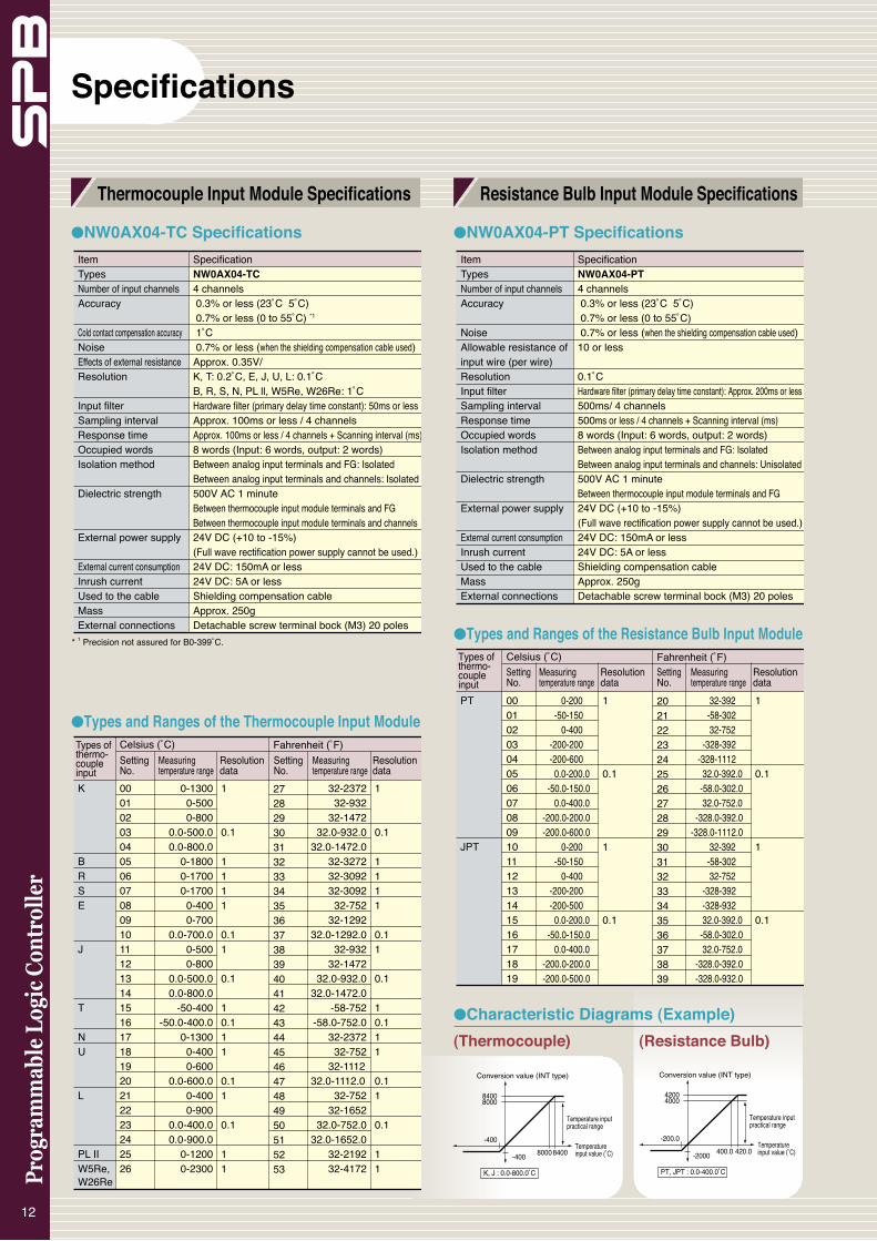
●NW0AX04-TC Specifications ●NW0AX04-PT Specifications
●Types and Ranges of the Thermocouple Input Module
●Types and Ranges of the Resistance Bulb Input Module
12
Item Types Number of input channels Accuracy
Noise Allowable resistance of input wire (per wire)Resolution Input filter Sampling interval Response time Occupied words Isolation method
Dielectric strength
External power supply
External current consumption Inrush current Used to the cable Mass External connections
SpecificationNW0AX04-PT4 channels 0.3% or less (23˚C 5˚C) 0.7% or less (0 to 55˚C) 0.7% or less (when the shielding compensation cable used)10 or less
0.1˚C Hardware filter (primary delay time constant): Approx. 200ms or less500ms/ 4 channels500ms or less / 4 channels + Scanning interval (ms)8 words (Input: 6 words, output: 2 words) Between analog input terminals and FG: Isolated Between analog input terminals and channels: Unisolated 500V AC 1 minute Between thermocouple input module terminals and FG 24V DC (+10 to -15%)(Full wave rectification power supply cannot be used.)24V DC: 150mA or less24V DC: 5A or lessShielding compensation cable Approx. 250gDetachable screw terminal bock (M3) 20 poles
Item Types Number of input channels Accuracy
Cold contact compensation accuracy Noise Effects of external resistance Resolution
Input filter Sampling interval Response time Occupied words Isolation method
Dielectric strength
External power supply
External current consumption Inrush current Used to the cable Mass External connections
SpecificationNW0AX04-TC4 channels 0.3% or less (23˚C 5˚C) 0.7% or less (0 to 55˚C) *1
1˚C 0.7% or less (when the shielding compensation cable used)Approx. 0.35V/ K, T: 0.2˚C, E, J, U, L: 0.1˚C B, R, S, N, PL ll, W5Re, W26Re: 1˚CHardware filter (primary delay time constant): 50ms or less Approx. 100ms or less / 4 channelsApprox. 100ms or less / 4 channels + Scanning interval (ms)8 words (Input: 6 words, output: 2 words) Between analog input terminals and FG: Isolated Between analog input terminals and channels: Isolated 500V AC 1 minute Between thermocouple input module terminals and FG Between thermocouple input module terminals and channels 24V DC (+10 to -15%)(Full wave rectification power supply cannot be used.)24V DC: 150mA or less24V DC: 5A or lessShielding compensation cable Approx. 250gDetachable screw terminal bock (M3) 20 poles
K
BRSE
J
T
NU
L
PL IIW5Re, W26Re
Celsius (˚C) 000102030405060708091011121314151617181920212223242526
Fahrenheit (˚F) 272829303132333435363738394041424344454647484950515253
0-1300 0-500 0-800 0.0-500.0 0.0-800.0 0-1800 0-1700 0-1700 0-400 0-700 0.0-700.0 0-500 0-800 0.0-500.0 0.0-800.0 -50-400 -50.0-400.0 0-1300 0-400 0-600 0.0-600.0 0-400 0-900 0.0-400.0 0.0-900.0 0-1200 0-2300
32-2372 32-932 32-1472 32.0-932.0 32.0-1472.0 32-3272 32-3092 32-3092 32-752 32-1292 32.0-1292.0 32-932 32-1472 32.0-932.0 32.0-1472.0 -58-752 -58.0-752.0 32-2372 32-752 32-1112 32.0-1112.0 32-752 32-1652 32.0-752.0 32.0-1652.0 32-2192 32-4172
1
0.1
1111
0.11
0.1
10.111
0.11
0.1
11
1
0.1
1111
0.11
0.1
10.111
0.11
0.1
11
Types of thermo-couple input
Measuring temperature range
Setting No.
Measuring temperature range
Setting No.
Resolution data
Resolution data
PT
JPT
Celsius (˚C) 0001020304050607080910111213141516171819
Fahrenheit (˚F) 2021222324252627282930313233343536373839
0-200 -50-150 0-400 -200-200 -200-600 0.0-200.0 -50.0-150.0 0.0-400.0 -200.0-200.0 -200.0-600.0 0-200 -50-150 0-400 -200-200 -200-500 0.0-200.0 -50.0-150.0 0.0-400.0 -200.0-200.0 -200.0-500.0
32-392 -58-302 32-752 -328-392 -328-1112 32.0-392.0 -58.0-302.0 32.0-752.0 -328.0-392.0 -328.0-1112.0 32-392 -58-302 32-752 -328-392 -328-932 32.0-392.0 -58.0-302.0 32.0-752.0 -328.0-392.0 -328.0-932.0
1
0.1
1
0.1
1
0.1
1
0.1
Types of thermo-couple input
Measuring temperature range
Measuring temperature range
Setting No.
Setting No.
Resolution data
Resolution data
8400
8400
8000
-400
-400 8000
Conversion value (INT type)
K, J : 0.0-800.0˚C
Temperature input value (˚C)
Temperature input practical range
(Thermocouple) (Resistance Bulb)
4200
420.0
4000
-200.0
-2000 400.0
PT, JPT : 0.0-400.0˚C
Conversion value (INT type)
Temperature input value (˚C)
Temperature input practical range
●Characteristic Diagrams (Example)
Specifications
Thermocouple Input Module Specifications Resistance Bulb Input Module Specifications
* 1 Precision not assured for B0-399˚C.

●RS-485 Adapter: NW0LA-RS4
<Simplified CPU link, basic specifications>
13
<General-purpose communication, basic specifications>
●RS-232C Adapter: NW0LA-RS2
*1 When using transmission rate 38400 bps, mount a ferrite core to the communication cable. For details, refer to RS-232C/RS-485 Communication Adapter (FEH405) Userʼs Manual.
Communication Adapter Specifications
Item SpecificationTransmission standard RS-485 Port 1 channel Transmission mode Half-duplex transmission Synchronization mode Start-stop transmission Transmission rate 1,200/2,400/4,800/9,600/19,200/38,400 bps Transmission distance 1km or less (with a transmission rate of 19,200 bps or less) Number of units connected 1:31 (max.) Connection method European type removable terminal board (5 pins) Cable Twisted pair cable with shield Transmission procedure Nonsequenced transmission / command set type transmission Transmission control code Binary (without code conversion) or ASCII (with code conversion), EBCDIC (with code conversion) Error control Hardware Vertical parity (parity bit), framing, overrun error Software Horizontal parity (BCC) Bit send-out order Sent from LSB to MSB Data length that can be sent/received Max. 512 bytes (depends on mode) at a time (seen from SPB) Start code None, data with a length of 1 to 5 bytes End code Data with a length of 1 to 5 bytes Character configuration Start bit: 1 bit Data bit : 7 or 8 bits Parity bit: None, odd, even Stop bit: 1 or 2 bits
Exte
rnal
inte
rface
Tran
smis
sion
spe
cific
atio
ns
Item SpecificationTransmission standard RS-232C Port 1 channel Transmission mode Half-duplex transmission Synchronization mode Start-stop transmission Transmission rate 1,200/2,400/4,800/9,600/19,200/38,400 bps *1 Transmission distance 15m or less Number of units connected 1: 1 Connection method D-Sub 9 pins, male Transmission procedure Nonsequenced transmission / command set type transmission Transmission control code Binary (without code conversion) or ASCII (with code conversion), EBCDIC (with code conversion) Error control Hardware Vertical parity (parity bit), framing, overrun error output type Software Horizontal parity (BCC) Bit send-out order Sent from LSB to MSB Data length that can be sent/received Max. 512 bytes (depends on mode) at a time (seen from SPB) Start code None, data with a length of 1 to 5 bytes End code Data with a length of 1 to 5 bytes Character configuration Start bit: 1 bit Data bit: 7 or 8 bits Parity bit: None, odd, even Stop bit: 1 or 2 bits
Tran
smis
sion
spe
cific
atio
nsEx
tern
al in
terfa
ce
Item Specification Connection target • SPB series basic unit • FLEX-PC NB series NP link micro, only with data link function Number of units connected 16 units max. Link capacity N mode: Variable: selected to 2, 4, 8, 16, or 32 words (1 station) (through parameter setting) SX mode: Fixed to 8 words (when operating mode 21H is selected) Link area Data register (D) area is used. (D1E00 to D1FFF) Communication form Bus Refresh time 130ms or less/16 stations, 32 words for each station (When the SX mode is selected, with a scan time of 5ms or less), excluding the case when the loader network function is used Communication access mode Polling/selecting mode Transmission level Conforms to EIA standard, RS-485. Transmission mode Half-duplex transmission Synchronization mode Start-stop transmission Transmission rate 115,200 bps (when the SX mode is selected) 19,200 bps (when the NB compatible mode is selected) Transmission distance 500m or less Connection method European type removable terminal board (5 pins) Cable Twisted pair cable with shield Master station Fixed to station 0 (station number set by parameters) Configuration Whether configuration is registered or not can be selected. registration (Registered to station 0 only when the SX mode is selected) Self diagnosis Communication monitoring (omitted data bits,addition) Insertion and removal Insertion and removal of link active wire are possible. of active wire
Syst
em s
peci
ficat
ions
Com
mun
icat
ion
spec
ifica
tions
Oth
ers
Com
mun
icat
ion
betw
een
link

14
20-points Basic Unit 30-points Basic Unit 40-points Basic Unit
60-points Basic Unit 16-points Input Expansion Unit 16-points Output Expansion Unit
32-points I/O Expansion Unit 60-points I/O Expansion Unit 16-points I/O Expansion Unit
++
Ry Ry
LLLL
LLLL
LLLLLL
LL
85 to 264V AC
RyRyRyRy
24V DCOUTPUT*2
+24V COM 0 2 4 6 8 A
0V COM 1 3 5 7 9 B
C E
D F
10 12 14 16
11 13 15 17
18 1A
19 1B
1C 1E
1D 1F
AC-L
AC-N 0 5 7 8
FG COM
2
9 C
COMA
B COM
D F 10
E
14
15COM
16 NC
17 COM 19 1B
18 1ANC
COM
COM
COM
COM
LLLL
1 3
COM
4 6 COM 11
12
13
LLLLLL
LL
Ry RyRy Ry Ry Ry Ry Ry
*1 *1
*1 *1 *1 *1 *1
*1 Power source
Internal power circuit
External Connection Diagrams
External Connection Diagrams
Note: 1 The figure above indicates external connection of the AC power supply/Ry output type.*2 The DC power supply is not applicable *3 The transistor type connection is shown below. *4 The terminal arrangement of the DC power supply is shown below.
to service power supply.FG
0V
24V+
24V DC+
COMY
+L
COMY
+
L
Tr sink
Tr source
Note: 2 The output terminal can be used as a pulse output terminal in the case of transistor output.Note: 3 For external connection of communication adapters, refer to RS-232C/RS-485 Communication Adapter (FEH405) Userʼs Manual.Note: 4 For external connection of analog unit, refer to Analog Unit (FEH407) User's Manual.
24V DCOUTPUT
++
Ry Ry Ry Ry
LLLLLLLL
85 to 264V AC*4
*2
*3
+24V COM 0 2 4 6 8 A
0V COM 1 3 5 7 9 B
AC-L
AC-N 2 3 4 6
FG COM COM COM COM COM 5 7
0
RyRy
1
Internal power circuit
*1 *1 *1 *1 *1
*1 Power source
++
RyRyRyRy RyRy
LLL L LL L LLL LL
LL
85 to 264V AC*4
*3
24V DCOUTPUT*2
+24V COM 0 2 4 6 8 A
0V COM 1 3 5 7 9 B
C E
D F
AC-L
AC-N 3 5 6 8
FG COM 2 4 COM 7 9
COM A C
B D
0
1
Internal power circuit
*1 Power source
*1*1
*1
++
RyRyRyRyRyRyRyRy
LLLL
LLLL
LLLLLLLL
*3
RyRy
24V DCOUTPUT*2
85 to 264V AC*4
AC-L
AC-N 2 3 4 6
FG COM 5 7
NC 8
9COM COM COM COM COM
A NC
B COM D F
C E
+24V COM 0 2 4 6 8 A
0V COM 1 3 5 7 9 B
C E
D F
10 12 14 16
11 13 15 17
0 1
Internal power circuit
*1 Power source
*1 *1 *1 *1 *1 *1 *1
++
Ry Ry
*3
LLLL
LLLL
LLLL
LLLL
LLLLLL LL
85 to 264V AC*4
RyRyRyRyRyRyRyRyRyRyRyRy
24V DCOUTPUT*2
+24V COM 0 2 4 6 8 A
0V COM 1 3 5 7 9 B
C E
D F
10 12 14 16
11 13 15 17
18 1A
19 1B
1C 1E
1D 1F
20 22
21 23
AC-L
AC-N 2 3 4 6
FG COM 5 7
NC 8
9COM COM COM COM COM
A NC
B COM D F
C E 10
11COM
12 NC
13 COM 15 17
14 16NC0 1
*1 Power source
Internal power circuit
*1 *1 *1 *1 *1 *1 *1 *1 *1
++
++
COM 1 3 4 6
2 5 70 COM
COM 1 3 4 6
2 5 70 COM
RyRyRyRy
LLLLLL
LL
RyRyRyRy
LLLL
*3
LLLL
COM
0 2
4 6
COM
1 3
5 7
COM
8 A
C E
COM
9 B
D F
*1
*1
*1 Power source
*1
*1
++
*3
COM 1 3 4 6
2 5 70 COM
RyRyRyRy
LLLLLL
LL
COM
8 A
C E
COM
9 B
D F
*1
*1
*1 Power source
+
+
Ry RyRy Ry Ry RyRy Ry
LLLL
*3
LLLL
LLLLLL
LL
COM 0 2 4 6 8 A
COM 1 3 5 7 9 B
C E
D F
COM
COM
COM
0 2 5
6 9 B1 3
7 8 A
C E
D F
4
COM
COM
COM
*1 *1
*1 *1
*1 Power source

Regardless of the input filter time setting, the pulse catch function allows the SPB to detect a pulse (min. 50µsec.) shorter than the scan time and output it at the following scan. It can be used for detecting an object which moves at high speed.
The SPB has an interrupt input function for interrupting normal program operation to initiate an interrupt program. It executes the interrupt program at the rise of the input from X0 to X3.
For the control of a machine which outputs at constant intervals, constant scan can be set to suppress the irregular I/O operating times. Constant scan can be set in the range from 1 to 255 in units of 1 msec.
Enabling various controls with standard functions
The SPB has a built-in high-speed counter which can count pulses at a maximum rate of 100kHz for a single phase or 50kHz for two phases.
●Specification
The SPB has two analog timers as standard. Each timer value is converted to a digital value of 0 to 255 in the SPB and stored in the internal memories.
<Operation Patterns>
●Pulse Width ModulationThe pulse width modulation instruction allows pulse output with variable pulse ON width and pulse interval with the following speci-fications, enabling light control.
15
Pulse Catch Function
The encoder output pulse can be input to the high-speed counter to control such a high-speed operation.
ON
OFFPulse ON width
Pulse interval
<Sample Application for Packing Machine>
Analog Timer
With basic units of the Tr output type, the terminal for output bits 0 and 1 can be used not only as a usual external output but as pulse output with up to 100kHz.The pulse output can be operated with dedicated instructions, al-lowing easy control based on pulse train output and pulse width modulation.●Pulse Train OutputPositioning control with servo motors and stepping motors is pos-sible without specialized units, based on the pulse train output in-struction, return-to-origin instruction, relative positioning instruction, absolute positioning instruction, and other positioning instructions.
Relative positioningAbsolute positioning
Return to origin
Frequency
Start Origin signal OFFOrigin signal ON
Frequency
Current position Target position
Rotational direction signal ON: Forward OFF: Reverse
Number of output pulses
� � � � �
Relative positioningAbsolute positioning
Return to origin
Frequency
Start Origin signal OFFOrigin signal ON
Frequency
Current position Target position
Rotational direction signal ON: Forward OFF: Reverse
Number of output pulses
� � � � �
Scan Scan ScanProgram execution
External signal
Internal relay
I/O
Melting signal
Encoder
Print signal
Cutting signal
Set time
Program execution Wait time Time is extended for the excess.
Set time Set time Set time
Control Functions
Pulse Train Output Function
Pulse train
ON/OFF
Item Specification 1-phase 2-phaseeMethod Preset increment counter Preset increment/decrement counterCount input signal 1-phase increment signal x 2 ch 90-deg.phase difference 2phase signal x 1 ch Counting pulse + Direction input x 1chControl input Reset Counting speed Max. 100kHz Max. 50kHz Counting range Unsigned binary 16 bits Signed binary 32 bitsMultiplication x1, x2 x2, x4 x1Reset Soft reset by control input and command registerPreset Soft reset by control command register
High-speed Counter Function
Constant Scan Function
Interrupt Input Function
Analog Timer Function

Programming Languages
Support for two programming languages on the same hardware• SX mode: MICREX-SX support (IEC 61131-3 compliant language)• N mode: FLEX-PC N support (non IEC 61131-3 compliant language)
SX-Programmer Standard Programming Support Tool
NP4H-SWN: N mode and SX mode programming support toolA support tool with a focus on usabilityProgram identically to the FLEX-PC N series
●Support for two different programming languages
Standard provides a choice of SX mode and N mode. In SX mode, create programs that comply with the IEC 61131-3 international standard (JIS B 3503). In N mode, leverage your program file and comment file assets for our FLEX-PC PLC series without modification.
●Familiar user interface The user interface and ladder programming support SPB pro-gramming equivalent to a FLEX-PC Windows-compatible PC loader. Support for full-keyboard operation is also handy for on-site debugging and maintenance. With a whopping 202 different instruction words, the possibilities for your programs are limited only by your imagination.
●Resume feature When the software is started, the previous edit/monitor position is automatically displayed. When you go on-line, monitoring starts at the position you were monitoring last time. When you are off-line, the system transitions to edit mode displaying the point you were editing last time.
●Full-fledged programming environment Programming allows all addresses to be specified, and allows off-line editing (edit and continue). Function block (FB) callers are expressed as block-format FBD, enabling you to identify in and out parameters at a glance (SX mode).
●Support for multiple programming languages SX mode supports ladder as well as ST language, while N mode supports mnemonic language. Select the programming language suited to the type of control you wish to perform.
16

●Link with spreadsheet program Directly copy comments edited/created in a spreadsheet program (Excel) into your program.
●Debugging features Powerful debugging facilities are provided, including step execu-tion, conditional monitoring, sampling traces, and fault analysis.
●Leverage your program assets In SX mode, you can copy and paste your programs from our FLEX-PC series PLCs. On-line help describes alternate methods for circuits and instructions that cannot be pasted in. In N mode, use your program and comment files as-is.
FLEX-PC loaderSX-Programmer Standard
Conversion(Copy & paste) Conversion scope:
All models (NB0 to NS)
1) Instruction address Address allocation rules can be customized 2) On-line help displays alternate methods
for instructions that cannot be converted automatically.
Limitations for FLEX-PC to SX mode1) The following conversions
are not possible: • MCS/MCR • OPDF • Direct I/O instructions • SFC instructions
Support tool connection cable: NWOH-CA3
+RS-232C/RS-422 signal converter:
NW0H-CNV
RS-232C
Personal computer
Standard(NP4H-SWN)
SPB
●System Configuration
●Operation environmentItemHardwareCPUHard disk CD-ROM unitMemory capacityKeyboardMouseIndicator
Communication interface OSPortabilityEnvironmental durability
SpecificationIBM-PC/AT compatible Intel Pentium 233MHz or higher (350MHz or higher recommended.) Free space of 220M bytes or more 1 unit (x 4 speed or faster), media: ISO 9660 format64M bytes or more 101 keyboard USB mouse, bus mouse, or PS2 mouse800 x 600-dots resolution or higher (1024 x 768-dots resolution or higher recommended) RS-232C: 9,600bps to 57,600k bps (Transmission speed is set automatically by the model for resource.) Windows95, 98, Me, NT4.0(SP6 or higher), 2000, XPDepends on a commercial mobile personal computer.Depends on environmental condition of a commercial personal computer.
17

Programming Languages
SX-Programmer Expert (D300win) Programming Support Tool
NP4H-SEDBV3: SX mode programming support tool A support tool with a focus on development efficiency Program using the same methods as on a microcomputer/PC
●Develop software more efficiently Complete compliance with IEC 61131-3 enables you to use programming at the POU/worksheet level to create a structured design divided by feature or process. This enables you to break up your design among multiple designers, greatly reducing program development time.
●Simulation features Expert (D300win) has a built-in software PLC especially for simulations. Use this feature to test your program logic without using an actual machine. The ability to monitor or forcibly turn on or off any signal should allow you to program and debug the SX series much faster.
●Modular programming Improve your programming efficiency through component re-use. • Programming with levels (variables)• Create components through function blocks (FBs)
●Multiple programming languages supported The five programming languages specified by the IEC standard (IL, ST, LD, FBD, and SFC) are all supported. Write your pro-grams in the combination of languages that best expresses the type of control you want to perform.
Instruction List (IL) language: Minimize application size
Structured Text (ST) language: A high-level language (IF-THEN-ELSE, etc.)
Ladder Diagram (LD) language: Relay-box replacement
Function Block Diagram (FBD) language: Data processing language
Sequential Function Chart (SFC) language: Application structure notation
●A rich set of instruction words With a whopping 202 different instruction words available, your ability to create programs is limited only by your imagination.
●Create function blocks of your own original circuits
Facilitate reuse of unchanging programs and circuits that you use frequently by converting them into function blocks. The creation of user function blocks does not require any special language: use any of the languages supported by Expert (D300win). Create libraries to effectively use just those features you want, without the need for debugging.
18

●System Configurations
Support tool connection cable: NW0H-CA3
+RS-232C/RS-422 signal converter:
NW0H-CNV
RS-232C
Personal computer
Expert <D300win>(NP4H-SEDBV3)
SPB
A “palm-top” handy loader and handy monitor for easy on-site use Handy loader: NW0H-NE Handy monitor: NW0H-S3E
●Basic Specifications
Handy Loader
Item SpecificationDisplay section LCD 16 characters x 2 lines with backlightKeyboard section 40 embossed sheet keys with buzzerUser program memory Built-in flash memory (handy loader only) Processor connection RS-422
Store
Copy
VerificationHandy Loader
2
3
1
FlashMemoryFlash
Memory
Replacing system software
SPB system software utility
N mode <==> SX mode
Replacing system software The SPB ships from the factory with N mode system software. In order to use it in SX mode, download the SX mode system software using the Standard or Expert (D300win) system utility version 3.1 or higher. Note: The SX mode is enabled for SPB main unit version of V**10 or up.
Item SpecificationHardware IBM-PC/AT compatibleCPU Intel Pentium 233MHz or higher (350MHz or higher recommended)Hard disk Free space of 220M bytes or higher Expert (D300win) system software: 100M bytes or higher Standard expansion FB package: 120M bytes or higher CD-ROM unit 1 unit (x 4 speed or faster), media: ISO 9660 formatMemory capacity 64M bytes or higher (when Windows XP used, 120M bytes or higher recommended)Keyboard 101 keyboard Mouse USB mouse, bus mouse, or PS2 mouseIndicator 800 x 600-dots resolution or higher (1024 x 768-dots resolution or higher recommended) Communication RS-232C: 9,600bps to 57,600k bpsinterface (Transmission speed is set automatically by the model for resource.)OS Windows NT4.0 (SP6 or higher), 2000, XPPortability Depends on a commercial mobile personal computer.Environmental Depends on environmental condition of a commercial durability personal computer.
●Operation environments
19
• Handy loader: N mode supported •••• Data monitoring, program editing • Handy monitor: SX mode supported •••• Data monitoring
●Palm size convenient for portable useThe units are extremely compact, measuring 90(W)x148(H)x38(D).
●Specially designed for easy data monitoring and setting useThe handy loader and the handy monitor are designed for easy portable use during maintenance and adjustment operations. They allow data for the SPB programmable controller to be monitored or set, and error messages to be displayed. Easy operation simplifies maintenance and adjustment work even for operators who have no knowledge of programming tools.
●Flash memory built in for user program storageTwo user programs with up to 32K steps can be stored in the internal memory of the handy loader. Stored programs can be copied to multiple basic units. The program in a basic unit can be
Handy loader Handy monitor
compared with the program in the handy loader, allowing easy secure copy operation.* Note that user data is not stored.

●FeaturesThis module allows easy remote maintenance system configuration simply by connecting the online adapter to the loader port without changing any program on the PLC (MICREX-SX SPH/SPB) side. The SPB is based on SX mode. ● Bi-directional communication between the master station
(personal computer) and slave station (SPH)● Diverse functions • Failure monitor function • Data accumulation function
• Integrated time monitor function • Communication functions of the each PLCs● Calendar functions (year, month, day, hour, minute, second),
and data backup functions (data memory, calendar IC memory) are provided too.
ItemPhysicalenvironment
Mechanicaloperating conditionElectricaloperating condition
Cooling systemInsulation characteristicPower supply method Current consumption
MassCalendar accuracyBattery type/operating life
Operating ambient temperatureStorage temperatureRelative humidityContaminationCorrosion resistanceOperating altitude/air pressureResistance to vibrationResistance to shockResistance to noise
Resistance to electrostatic dischargeResistance to radiation electromagnetic field
Insulation resistance
Specification0 to 55ºC (without condensation)
-20 to 70ºC (without condensation)20 to -90%RH (without condensation)Contamination level 2No corrosive gas is present, no organic solvent adhesionAltitude of 2000m or less (air pressure of 70kPa or higher during transportation)One amplitude: 0.15mm, constant acceleration: 9.8m/s2, 2 hours for each direction, 6 hours totalPeak acceleration: 294m/s2, 3 times for each directionNoise simulator method, rise time of 1ns, pulse width of 1s, 1kVContact discharge method: 6kV, air discharge method: 8kV
10V/m (80 to 1000MHz)
Natural cooling10M or more (between connectors and ground) with a 500V DC meggerSupplies 24V DC from PC or 12V DC from AC adapter.24V: 60mA or less12V: 120mA or lessApprox. 320g 90 seconds/month (25ºC, conduction)Lithium primary battery 3.6VNP8P-BT (Fuji Electric FA Components & Systems Co., Ltd.)/ 5 years (ambient temperature of 25ºC)
Note: For operating environment, take into consideration the specifications of the communication devices used.* Use the AC adapter only at the time of initial setup data transmission. Do not use it for connection with SPH/SPB (SX mode).
Functional specifications Mode Online adapter mode Loader mode Remote mode
Initial setup mode
Memory clear mode
Contents Execution mode of various monitor functions Monitors SPH/SPB (SX mode) programming monitor locally. Monitors SPH/SPB (SX mode) programming monitor from a remote site. Writes setup data necessary for various monitor functions using the initial setup loader. Backup memory initialization (clear) mode
●System Configurations
●Initial setup loader (Model: FOA-LOADER2-CD) <Japanese version>
Creates initial setup data (each function setup).• Sets the failure monitor, data accumulation, integrated
time monitor functions and registers AT commands for communication.
Writes the initial setup data to the online adapter.Reads the initial setup data from the online adapter.
●Master Station Monitoring Software (Model: FOA-CENTER2-CD) <Japanese version>
Slave station monitor function (reception of notification from slave station) • Failure monitor function • Data accumulation function
• Integrated time monitor function20
Facilitating configuration of remote maintenance systemOnline Adapter: FOA-ALFA2
●Specifications
General specifications
Online Adapter
Communication device
Communication device
Online adapterFOA-ALFA2
Communication network
Specialized connection cable (option)NW0H-CA3
Performs various monitor functions and communication setup using the initial setup loader (FOA-LOADER2-CD).
Performs remote monitor, e-mail sending, and data monitoring using the master station monitoring software (FOA-CENTER2-CD).
Online Adapter
Access from the master monitor software (personal computer) to slave station.
• Reads data accumulated in the online adapter.• Automatically collects data by time specification (with circuit
connection each time).• Updates the initial setup data from a remote site. (Remote
update function)• Uses the personal computer loader software from a remote
site.Other functions
• Saves receive data as CSV files.• Monitors accumulated data in bar graph form.• Upon reception of failure information, automatically
transfers the failure information to E-mail-based mobile tool through the internet using the online adapter.

For r
atin
gs s
ee in
stru
ctio
n m
anua
l
NW0A -MR
Anal
og U
nit
848 87
8290
284
4
4
• Analog Input Unit: NW0AX04-MR• Analog Output Unit: NW0AY04-MR• Analog I/O Unit: NW0AW03-MR• Thermocouple Input Module: NW0AX04-TC • Resistance Bulb Input Module: NW0AX04-PT
2-ø4.5 (for M4 screw)
81
90
40
W2
W1
*1
*1RCV
SND
RS-232C
SDA
RDA
SGRDB
SDB
RS-485
RUN
304048
304048
90
(51.5) 867
90
(17.5) 867
2-ø4.5 (for M4 screw)
2-ø4.5 (for M4 screw)
8080
Approx. 50
Approx. 50
•RS-232C Adapter: NW0LA-RS2
•RS-485 Adapter: NW0LA-RS4
21
38 90
ø8
82
148
• �������• ��������
Analog Unit Handy Loader / Handy Monitor
Dimensions [mm]
Basic Unit / Expansion Unit Communication Adapter
W1 70100130170 54100170
20-point basic unit30-point basic unit40-point basic unit60-point basic unit16-point expansion unit32-point expansion unit60-point expansion unit
W2 80110140180 64110180
Note: The mounting hole of a basic unit/expansion unit of 60 point type is on four corners. Other units has not the mounting hole on “ *1 ” part.
Note: When analog unit and basic unit are installed and connected together, the distance between them must be approx. 10 to 20 mm.

22
Ordering InformationsCertificated Exceptions Under planing No planing ---Standards
Note: Pulse train output and PWM output are not available for relay output. *1 50mm expansion cable is supplied as accessory. *2 The order code is shown in ( ). *3 For more information about RoHS based on products, please contact our sales section. Microsoft, Windows, Windows NT, Windows XP are trademarks of Microsoft Corporation in the USA and other countries. Pentium is trademarks or registered trademarks of Intel Corporation. And other companies name, products name in this catalog, are trademarks or registered trademarks of the each companies.
20-points basic unit
30-points basic unit
40-points basic unit
60-points basic unit
16-points expansion unit *1
32-points expansion unit *1
60-points expansion unit *1Analog Input UnitAnalog Output UnitAnalog I/O UnitThermocouple Input ModuleResistance Bulb Input Module RS-232C adapter RS-485 adapterMemory cardBatteryExpansion cableSX-Programmer Standard SX-Programmer Expert Loader software package for personal computer Handy loader Handy monitorPC connection adapter(Signal converter)Loader cable
Online adapter Initial setup loader software <Japanese version>Master station monitoring software <Japanese version>
NW0P20R-31NW0P20T-31NW0P20U-31NW0P20R-34NW0P20T-34NW0P20U-34NW0P30R-31NW0P30T-31NW0P30U-31NW0P30R-34NW0P30T-34NW0P30U-34NW0P40R-31NW0P40T-31NW0P40U-31NW0P40R-31CNW0P40T-31CNW0P40U-31CNW0P40R-34NW0P40T-34NW0P40U-34NW0P40R-34CNW0P40T-34CNW0P40U-34CNW0P60R-31NW0P60T-31NW0P60U-31NW0P60R-31CNW0P60T-31CNW0P60U-31CNW0P60R-34NW0P60T-34NW0P60U-34NW0P60R-34CNW0P60T-34CNW0P60U-34CNW0E16XNW0E16R-0NW0E16T-0NW0E16U-0NW0E16R-3NW0E16T-3NW0E16U-3NW0E32R-3NW0E32T-3NW0E32U-3NW0E60R-31
NW0AX04-MRNW0AY04-MRNW0AW03-MRNW0AX04-TCNW0AX04-PTNW0LA-RS2NW0LA-RS4NW8PMF-8NW8P-BTNW8C-EP6NP4H-SWNNP4H-SEDBV3NN4NWN-SB
NW0H-NENW0H-S3ENW0H-CNV
NW0H-CA3
FOA-ALFA2 (NP1L-FOA) *2FOA-LOADER2-CD (NL4N-WNOL) *2FOA-CENTER2-CD (NL4N-WNOC) *2
Products names Types (= Ordering codes)
Specifications Power specifications 100 to 240V AC
24V DC
100 to 240V AC
24V DC
100 to 240V AC
24V DC
100 to 240V AC
24V DC
No power source
Provided power source
Multi-range input: 4ch, Resolution: 14 bits (voltage / current)Multi-range output: 4ch, Resolution: 14 bits (voltage / current)Multi-range input: 2ch, Multi-range output: 1ch, Resolution: 10 bits (voltage / current)Input: 4ch Input: 4ch RS-232C 1 channel (general-purpose communication mode, loader interface mode)RS-485 1 channel (general-purpose communication mode, loader interface mode, simplified CPU link mode)Flash ROM (for 40/60-points basic unit)Lithium battery for backupExpansion cable: 600 mm (For 60-points expansion unit, only one cable can be used by one system)For N mode/ SX mode, CD-ROM, English/Japanese edition For SX mode, CD-ROM, English/Japanese edition, Version 3 For N mode, CD-ROM, English/Japanese edition
English type: Loader cable (Type: NB-EC0100 1000mm) supplied as accessory English type: Loader cable (Type: NW0H-CA3 1000mm) supplied as accessoryFor personal computer loader-basic unit connection, RS-232C/RS-422 conversion, (combined with the optional loader cable: NW0H-CA3)Connection cable for personal computer loader-basic unit: 3000 mm straight cable(combined with the optional PC connection adapter: NW0H-CNV) Adapted to MICREX-SX SPH/SPB (SX mode ) series. CD-ROM, (Adapted to SPH versions: LV3.00.25 or higher)
CD-ROM, (Adapted to SPH versions: LV3.00.24 or higher)
Input specifications 24V DC 12 points
24V DC 16 points
24V DC 24 points
24V DC 36 points
24V DC 16 points–
24V DC 8 points
24V DC 16 points
24V DC 32 points
Output specifications Ry 8 points Tr sink 8 points Tr source 8 points Ry 8 points Tr sink 8 points Tr source 8 points Ry 14 points Tr sink 14 points Tr source 14 points Ry 14 points Tr sink 14 points Tr source 14 points Ry 16 points Tr sink 16 points Tr source 16 points Ry 16 points Tr sink 16 points Tr source 16 points Ry 16 points Tr sink 16 points Tr source 16 points Ry 16 points Tr sink 16 points Tr source 16 points Ry 24 points Tr sink 24 points Tr source 24 points Ry 24 points Tr sink 24 points Tr source 24 points Ry 24 points Tr sink 24 points Tr source 24 points Ry 24 points Tr sink 24 points Tr source 24 points –Ry 16 pointsTr sink 16 pointsTr source 16 pointsRy 8 pointsTr sink 8 pointsTr source 8 pointsRy 16 pointsTr sink 16 pointsTr source 16 pointsRy 28 points
CEStandards
UL/cULRoHS
*3LR
------------------
---
---
---
---
Calendar functionBuilt-inNon
------------------
---
---
---
---
------------------
---
---
---
---

23
Product Warranty
�������������������������������������������
The warranty of this product is as follows unless the special instructions state otherwise in the quote, contract, catalogue, or specifications at the time of quote or order.The purpose or area of use may be limited, and a routine checkup may be required depending on the product. Please contact the distributor from which you purchased the product from, or Fuji Electric for further information.Please conduct prompt incoming inspection of the product upon purchase or delivery. Also, please give enough consideration to management and maintenance of the product prior to accepting the product.
������������������������������������������������(1) The period of the warranty is effective until the earliest of either a year from the date of purchase or,
eighteen (24) months from the date of manufacture printed on the plate.(2) The above period may not be applicable in case the particular environment, conditions or frequency
of use affects the lifetime of the product.(3) The warranty for the parts repaired by Fuji Electric service department is effective for six months
from the date of repair.������������(1) If malfunction occurs in the period of warranty due to Fuji Electric, the malfunctioning parts are
exchanged or repaired for free at the point of purchase or delivery. However, the warranty does not apply to the following cases.1) The malfunction occurs due to inappropriate conditions, environment, handling or usage that is
not instructed in a catalogue, instruction book or user's manual.2) The malfunction is caused by the factors that do not originate in the purchased or delivered
product.3) The malfunction is caused by other devices or software design that does not originate in Fuji
Electric products.4) The malfunction occurs due to an alteration or repair that is not performed by Fuji Electric.5) The malfunction occurs because the expendable parts listed in an instruction book or catalogue
were not maintained nor exchanged in an appropriate manner.6) The malfunction occurs due to factors that were not foreseeable by the practical application of
science and technology at the time of purchase or delivery.7) The malfunction occurs because the product is used for an unintended purpose.8) The malfunction occurs due to a disaster or natural disaster that Fuji Electric is not responsible
for.(2) The warranty is only applicable to the single purchased delivered product.(3) The warranty covers only the area stated in above (1). Any damage induced by the malfunction of
the purchased or delivered product, including the damage or loss to a device or machine and passive damages, is not covered by the warranty.
�������������������������Malfunction is to be diagnosed temporarily by the purchaser. This diagnosis can be conducted by Fuji Electric or its delegated service provider with due charge upon the request from the purchaser. The charge is to be paid by the purchaser at the rate stipulated in the rate schedule of Fuji Electric.
���������������������������������Regardless of the time period of the occurrence, Fuji Electric is not liable for the damage caused by the factors Fuji Electric is not responsible for, opportunity loss of the purchaser caused by malfunction of Fuji Electric product, passive damages, damage caused due to special situations regardless of whether it was foreseeable or not, and secondary damage, accident compensation, damage to products that were not manufactured by Fuji Electric, and compensation towards other operations.
�����������������������������������������������������������������������������������������������������������The discontinued models (products) can be repaired for seven years from the date of discontinuation. Also, most spare parts used for repair are provided for seven years from the date of discontinuation. However, some electric parts may not be obtained due to their short life cycle. In this case, repair or provision of the parts may be difficult in the above period. Please contact Fuji Electric or its service providers for further information.
�����������������Standard products that do not entail application setting or adjustment are regarded as received by the purchaser upon delivery. Fuji Electric is not responsible for local adjustments and test runs.
����������The price of the delivered or purchased products does not include the service fee for the technician. Please contact Fuji Electric or its service providers for further information.
�����������������������Above contents shall be assumed to apply to transactions and use of the country where you purchased the products. Consult the local supplier or Fuji for the detail separately.

Fuji Electric FA Components & Systems Co., Ltd.
Mitsui Sumitomo Bank Ningyo-cho Bldg.,5-7, Nihonbashi Odemma-cho, Chuo-ku, Tokyo 103-0011, Japan
Phone: +81-3-5847-8011Fax: +81-3-5847-8172URL http://www.fujielectric.co.jp/fcs/eng/ Printed on 100% recycled paper using soy-based ink
Printed in Japan 2007-1 (A07e/D01) Sh 30 FIS LEH984eMaterials covered in this document are subject to revision due to the modification of the product.
Appearance and specifications are subject to change without prior notice for the purpose of product improvement.
Safety Considerations For safe operation, before using the product read the instruction manual or user manual that comes with the product carefully or consult the Fuji sales representative from which you purchased the product. Products introduced in this catalog have not been designed or manufactured for such applications in a system or
equipment that will affect human bodies or lives. Customers, who want to use the products introduced in this catalog for special systems or devices such as for
atomic-energy control, aerospace use, medical use, passenger vehicle, and traffic control, are requested to consult the Fuji sales division.
Customers are requested to prepare safety measures when they apply the products introduced in this catalog to such systems or facilities that will affect human lives or cause severe damage to property if the products become faulty.
For safe operation, wiring should be conducted only by qualified engineers who have sufficient technical knowledge about electrical work or wiring.