lepy series 240 g · 125.6 mm 20.5 mm 30 mm 138.6 mm 21 mm 41 page 383 page 374 page 547 size: 6,...
TRANSCRIPT

125.6 mm
20.5 mm
30 mm
138.6 mm
21 mm
41 mm
Page 383
Page 374
Page 547
Size: 6, 10
Size: 6, 10
Rod Type LEPY Series
Slide Table Type LEPS Series
∗ LEPY6-25
240 gWeight
∗ LEPS6-25
290 gWeight
Linear guide integrated
64 points positioning Input using controller setting kit or teaching box
Step data input typeLECP6 Series
14 points positioning Control panel setting
Programless typeLECP1 Series
Pulse input typeLECPA Series
Step Motor (Servo/24 VDC) Controller/Driver
CC-Link direct input typeLECPMJ Series∗
EtherCAT®/EtherNet/IP™/PROFINET/DeviceNet™/ IO-Link direct input typeJXCE1/91/P1/D1/L1 Series
∗ Not applicable to CE.
Maximum pushing force: 50 N Positioning repeatability: ±0.05 mm Possible to set position, speed and force. (64 points)
Step Motor (Servo/24 VDC)
Compact andlightweight
Electric Actuators
Miniature Rod Type/Miniature Slide Table Type
LEPY/LEPS Series®
RoHS
369 B

Electric Actuators
Body mountingthrough-hole Body mounting
through-hole
Linear guide
Miniature Rod Type
Rod Type
Miniature Slide Table Type
Compact and lightweightLEPY Series
(LEPY6-25)
240 gWeight
LEPS Series
(LEPS6-25)
290 gWeight
Can be mounted close together.
Application Examples
Slide Table Type
Pick and place Delivery
Alignment Press fitting
Motor type can be selected to suit the application.(Size 10 only) High pushing force type/basic type Compact and lightweight motor type
Manual override screwFor rod/table operation.Adjustment operation possible when power OFF
Variations
SizeBasic
Screwlead
Pushing force [N] Stroke[mm]
6
10
6
10
Type
Rod typeLEPY Series
Slide tabletype
LEPS Series
4
8
5
10
4
8
5
10
14 to 20
7 to 10
25 to 50
12.5 to 25
14 to 20
7 to 10
25 to 50
12.5 to 25
Compact
—
—
24 to 40
12 to 20
—
—
24 to 40
12 to 20
Basic Basic Basic
Max. work load [kg](Horizontal)
2.0
1.0
6.0
3.0
1.0
0.75
2.0
1.5
Compact
—
—
4.0
2.0
—
—
2.0
1.5
Max. work load [kg](Vertical)
0.5
0.25
1.5
1.0
0.5
0.25
1.5
1.0
Compact
—
—
1.5
1.0
—
—
1.5
1.0
Max. speed [mm/s](Horizontal)
150
300
200
350
150
300
200
350
Compact
—
—
200
350
—
—
200
350
255075
2550
Page
Page374
Page383
370

LEPY/LEPS Series
Mounting VariationsMounting from various directions
Can be selected from 4 directions.
Motor Cable Entry Direction
Top entry (Basic model)
Bottom entry (When selecting “U”)
Entry on the right side (When selecting “R”)
Entry on the left side (When selecting “L”)
For slide table type, mountingfrom both sides is possible.
For slide table type, bodytapped from both sides.
Side mounting (Body mounting through-hole) Side mounting (Body tapped)
Bottom mounting (Body tapped) Axial mounting ∗ Rod type only (Body tapped)
371
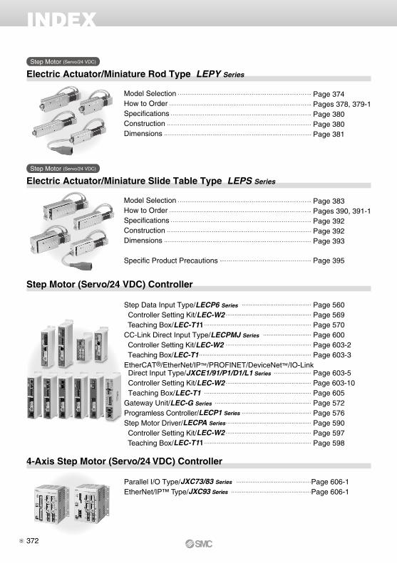
INDEX
Electric Actuator/Miniature Rod Type LEPY Series
Electric Actuator/Miniature Slide Table Type LEPS Series
Step Motor (Servo/24 VDC) Controller
Model Selection Page 374How to Order Pages 378, 379-1Specifications Page 380Construction Page 380Dimensions Page 381
Model Selection Page 383How to Order Pages 390, 391-1Specifications Page 392Construction Page 392Dimensions Page 393
Specific Product Precautions Page 395
Step Motor (Servo/24 VDC)
Step Motor (Servo/24 VDC)
4-Axis Step Motor (Servo/24 VDC) Controller
Parallel I/O Type/JXC73/83 Series ……………………………………Page 606-1EtherNet/IP™ Type/JXC93 Series ………………………………………Page 606-1
Step Data Input Type/LECP6 Series ………………………………… Page 560 Controller Setting Kit/LEC-W2 ………………………………………… Page 569 Teaching Box/LEC-T11 …………………………………………………… Page 570CC-Link Direct Input Type/LECPMJ Series ……………………… Page 600 Controller Setting Kit/LEC-W2 ………………………………………… Page 603-2 Teaching Box/LEC-T1 ……………………………………………………… Page 603-3EtherCAT®/EtherNet/IP™/PROFINET/DeviceNet™/IO-Link Direct Input Type/JXCE1/91/P1/D1/L1 Series ………………… Page 603-5 Controller Setting Kit/LEC-W2 ………………………………………… Page 603-10 Teaching Box/LEC-T1 …………………………………………………… Page 605Gateway Unit/LEC-G Series ……………………………………………… Page 572Programless Controller/LECP1 Series ………………………………… Page 576Step Motor Driver/LECPA Series ………………………………………… Page 590 Controller Setting Kit/LEC-W2 ………………………………………… Page 597 Teaching Box/LEC-T11 …………………………………………………… Page 598
372B

Miniature Rod Type LEPY Series
Miniature Slide Table Type LEPS Series
Electric Actuators
Step Motor (Servo/24 VDC)
Step Motor (Servo/24 VDC)
373

T1
a1 a2
L
Reaches thetarget position
Spe
ed: V
[mm
/s]
Time [s]
T2 T3 T4
W
Speed [mm/s]
Wor
k lo
ad [k
g]
0.6
0.5
0.4
0.3
0.2
0.1
04000 100 200 300
Lead 4 (LEPY6K)
Lead 8 (LEPY6J)
Step 1 Check the work load–speed. <Speed–Work load graph>
Step 2 Check the cycle time.
Workpiece mass: 0.2 [kg]
Speed: 200 [mm/s]
Acceleration/Deceleration: 3000 [mm/s2]
Stroke: 40 [mm]
Workpiece mounting condition: Vertical upwarddownward transfer
Operatingconditions
Selection Procedure
Positioning Control Selection Procedure
Selection Example
Step 1Check the work load–speed.(Vertical transfer) Step 2 Check the cycle time.
Calculate the cycle time using the following calculation method.
Cycle time T can be found from the following equation.
Select the target model based on the workpiece mass and speed with reference to the <Speed–Work load graph>.
Selection example) The LEPY6J is temporarily selected based on the graph shown on the right side.
T4: Settling time varies depending on the conditions such as motor types, load and in position of the step data. Therefore, calculate the settling time with reference to the following value.
T2: Constant speed time can be found from the following equation.
T1: Acceleration time and T3: Deceleration time can be obtained by the following equation.
L : Stroke [mm] ··· (Operating condition)V : Speed [mm/s] ··· (Operating condition)a1: Acceleration [mm/s2] ··· (Operating condition)a2: Deceleration [mm/s2] ··· (Operating condition)
T1: Acceleration time [s] ··· Time until reaching the set speedT2: Constant speed time [s] ··· Time while the actuator is
operating at a constant speedT3: Deceleration time [s] ··· Time from the beginning of the
constant speed operation to stopT4: Settling time [s] ··· Time until positioning is completedCalculation example)
T1 to T4 can be calculated as follows.
T1 = V/a1 = 200/3000 = 0.067 [s], T3 = V/a2 = 200/3000 = 0.067 [s]
T4 = 0.2 [s]
Therefore, the cycle time can be obtained as follows.T = T1 + T2 + T3 + T4 = 0.067 + 0.133 + 0.067 + 0.2 = 0.467 [s]
T2 = = = 0.133 [s]L – 0.5 · V · (T1 + T3)
V
40 – 0.5 · 200 · (0.067 + 0.067)
200
<Speed–Work load graph>(LEPY6/Step motor)
* It is necessary to mount a guide outside the actuator when used for horizontal transfer.When selecting the target model, refer to page 380 for the horizontal work load in the
specifications, and page 380 for the precautions.
Based on the above calculation result, the LEPY6J-50 is selected.
T = T1 + T2 + T3 + T4 [s]
T1 = V/a1 [s]
T4 = 0.2 [s]
T3 = V/a2 [s]
T2 = [s]L − 0.5 · V · (T1 + T3)
V
Step Motor (Servo/24 VDC) Electric Actuator/Miniature Rod TypeLEPY Series
Model SelectionLEPY SeriessPages 378, 379-1
374A

B
Pushing control
AP
ositi
on
Time
Lead 5 (LEPY10LK)
Lead 10 (LEPY10LJ)
0
10
20
30
40
50
60% 70% 75% 80% 90% 100%
Set value of pushing force [%]
For
ce [N
]Duty ratio = A/B x 100 [%]
Step 1 Check the duty ratio. <Conversion table of pushing force–duty ratio>
Step 2 Check the pushing force. <Set value of pushing force–Force graph>
Mounting condition: Horizontal (pushing) Duty ratio: 70 [%]
Jig weight: 0.05 [kg] Speed: 150 [mm/s]
Pushing force: 30 [N] Stroke: 40 [mm]
Operatingconditions
Selection Procedure
Pushing Control Selection Procedure
Selection Example
Select the target model based on the set value of pushing force and force with reference to the <Set value of pushing force–Force graph>.
Selection example)Based on the graph shown on the right side,Set value of pushing force: 75 [%]Pushing force: 30 [N]Therefore, the LEPY10LK is temporarily selected.
Step 3 Check the lateral load on the rod end. <Allowable lateral load on the rod end>Confirm the allowable lateral load on the rod end of the actuator: LEPY10L, which has been selected temporarily with reference to the <Allowable lateral load on the rod end>.
Selection example)Based on the table below,Jig weight: 0.05 [kg] ≈ 0.5 [N]Therefore, the lateral load on the rod end is in the allowable range.
Select the [Pushing force] from the duty ratio with reference to the <Conversion table of pushing force–duty ratio>.
Selection example)Based on the table below,Duty ratio: 70 [%]Therefore, the set value of pushing force will be 80 [%].
* [Set value of pushing force] is one of the step data input to the controller.* [Continuous pushing time] is the time that the actuator can continuously keep pushing.
<Set value of pushing force–Force graph>(LEPY10L)
<Conversion table of pushing force–duty ratio>(LEPY10L)
<Allowable lateral load on the rod end>
Based on the above calculation result, the LEPY10LK-50 is selected.
Step 1 Check the duty ratio. Check the lateral load on the rod end.
Step 2 Check the pushing force. Step 3
* The duty ratio is a ratio at the time that can keep being pushed.
Model Allowable lateral load on the rod end [N]
LEPY6 (Basic) 0.50
LEPY10 (Basic) 1.0
LEPY10L (Compact) 1.0
Set value ofpushing force [%]
Duty ratio[%]
Continuouspushing time [minute]
70 or less 100 —
80 70 10
100 50 5
375
Model Selection LEPY SeriesStep Motor (Servo/24 VDC)

2.5
2
1.5
1
0.5
04000 100
Speed [mm/s]
Wor
k lo
ad [k
g]
200 300
Lead 4 (LEPY6K)
Lead 8 (LEPY6J)
0.6
0.5
0.4
0.3
0.2
0.1
04000 100
Speed [mm/s]W
ork
load
[kg]
200 300
Lead 4 (LEPY6K)
Lead 8 (LEPY6J)
7
6
5
2
3
4
1
04003000 100
Speed [mm/s]
Wor
k lo
ad [k
g]
200
Lead 5 (LEPY10LK)
Lead 10 (LEPY10LJ)
3
2.5
2
1.5
1
0.5
04003000 100
Speed [mm/s]
Wor
k lo
ad [k
g]
200
Lead 5 (LEPY10LK)
Lead 10 (LEPY10LJ)
7
6
5
3
1
4
2
04003000 100
Speed [mm/s]
Wor
k lo
ad [k
g]
200
Lead 5 (LEPY10K)
Lead 10 (LEPY10J)
3
2.5
2
1.5
1
0.5
04003000 100
Speed [mm/s]
Wor
k lo
ad [k
g]
200
Lead 5 (LEPY10K)
Lead 10 (LEPY10J)
LEPY6 (Basic)
Horizontal
Speed–Work Load Graph (Guide)
Vertical
LEPY10L (Motor size: Compact)
LEPY10 (Motor size: Basic)
Horizontal
Horizontal
Note) The maximum value of the work load for the positioning operation. An external guide is necessary to support the load.The actual work load and transfer speed change according to the condition of the external guide.
Vertical
Vertical
∗ The following graph shows the values when moving force is 150%.
376
LEPY SeriesStep Motor (Servo/24 VDC)

Lead 4 (LEPY6K)
Lead 8 (LEPY6J)
0
5
10
15
20
25
70% 80% 90% 100%
Set value of pushing force [%]∗
For
ce [N
]
Lead 5 (LEPY10K)
Lead 10 (LEPY10J)
0
10
20
30
40
50
60
50% 60% 70% 80% 90% 100%
Set value of pushing force [%]∗
For
ce [N
]
Lead 5 (LEPY10LK)
Lead 10 (LEPY10LJ)
0
10
20
30
40
50
60% 70% 80% 90% 100%
Set value of pushing force [%]∗
For
ce [N
]
F
Allowable Lateral Load on the Rod End
LEPY6 (Basic)
LEPY10 (Basic) LEPY10L (Compact)
Set Value of Pushing Force–Force Graph (Guide)
* Set values for the controller.
Set value of pushing force [%]
Duty ratio[%]
Continuous pushingtime [minute]
70 or less 100 —
80 70 10
100 50 5
Set value of pushing force [%]
Duty ratio[%]
Continuous pushingtime [minute]
60 or less 100 —
70 30 3
100 15 1
Model Allowable lateral load on the rod end [N]
LEPY6 (Basic) 0.50
LEPY10 (Basic) 1.0
LEPY10L (Compact) 1.0
Set value of pushing force [%]
Duty ratio[%]
Continuous pushingtime [minute]
70 100 —
80 70 10
100 50 5
377
Model Selection LEPY SeriesStep Motor (Servo/24 VDC)

Confirm that the combination of the controller/driver and the actuator is correct.
The actuator and controller/driver are sold as a package.
<Check the following before use.>q Check the actuator label for model number. This matches the controller/driver.w Check Parallel I/O configuration matches (NPN or PNP).
* Refer to the operation manual for using the products. Please download it via our website, http://www.smcworld.com
How to Order
q Size
t Motor cable mounting direction
e Lead screw type [mm] r Stroke [mm]
[CE-compliant products]q EMC compliance was tested by combining the electric actuator LEP series and
the controller LEC series.The EMC depends on the configuration of the customer’s control panel and the relationship with other electrical equipment and wiring. Therefore, conformity to the EMC directive cannot be certified for SMC components incorporated into the customer’s equipment under actual operating conditions. As a result , it is necessary for the customer to verify conformity to the EMC directive for the machinery and equipment as a whole.
w CC-Link direct input type (LECPMJ) is not CE-compliant.[UL-compliant products]When conformity to UL is required, the electric actuator and controller/driver should be used with a UL1310 Class 2 power supply.
Caution
w Motor size
q w
Symbol Motor size Applicable size
Nil Basic 6, 10
L Compact 10
Symbol Stroke
25 25
50 50
75 75
SymbolScrew lead
LEPY6 LEPY10K 4 5
J 8 10
Nil
Top entry
L
Entry on the left side
U
Bottom entry
R
Entry on the right side
610
Step Motor (Servo/24 VDC)
Electric ActuatorMiniature Rod TypeLEPY Series LEPY6, 10
Refer to page 379-1 for the communication protocols EtherCAT®, EtherNet/IP™, PROFINET, DeviceNet™, and IO-Link.
LEPY 10 K 50 16NR1q w e r t uy i o
378
Applicable to the LEC series
B

i I/O cable length [m]∗1, Communication plug
∗1 When “Without controller/driver” is selected for controller/driver types, I/O cable cannot be selected. Refer to page 568 (For LECP6), page 582 (For LECP1) or page 596 (For LECPA) if I/O cable is required.
∗2 When “Pulse input type” is selected for controller/driver types, pulse input usable only with differential. Only 1.5 m cables usable with open collector.
∗3 For the LECPMJ, only “Nil”, “S” and “T” are selectable since I/O cable is not included.
∗1 For details about controller/driver and com-patible motor, refer to the compatible con-troller/driver below.
∗2 Not applicable to CE.∗3 When pulse signals are open collector, order
the current limiting resistor (LEC-PA-R-) on page 596 separately.
u Controller/Driver type∗1
Compatible Controller/Driver
Type
Step datainput type
CC-Link direct input type
Programless type Pulse input type
Series LECP6 LECPMJ LECP1 LECPA
FeaturesValue (Step data) input
Standard controllerCC-Link direct input
Capable of setting up operation (step data)without using a PC or teaching box
Operation by pulse signals
Compatible motor Step motor (Servo/24 VDC)Maximum number of step data 64 points 14 points —Power supply voltage 24 VDCReference page Page 560 Page 600 Page 576 Page 590
∗ DIN rail is not included. Order it separately.
o Controller/Driver mountingNil Screw mounting
D DIN rail mounting∗
Nil Without controller/driver
6N LECP6(Step data input type)
NPN
6P PNP
1N LECP1(Programless type)
NPN
1P PNP
MJ LECPMJ∗2
(CC-Link direct input type)—
AN LECPA∗3
(Pulse input type)NPN
AP PNP
Nil Without cable (Without communication plug connector)∗3
1 1.5
3 3∗2
5 5∗2
S Straight type communication plug connector∗3
T T-branch type communication plug connector∗3
y Actuator cable type/lengthNil Without cable
S1 Standard cable 1.5 m
S3 Standard cable 3 m
S5 Standard cable 5 m
R1 Robotic cable 1.5 m
R3 Robotic cable 3 m
R5 Robotic cable 5 m
R8 Robotic cable 8 m∗1
RA Robotic cable 10 m∗1
RB Robotic cable 15 m∗1
RC Robotic cable 20 m∗1
∗1 Produced upon receipt of order (Robotic cable only)
∗2 The standard cable should only be used on fixed parts.For use on moving parts, select the robotic cable.
379
Electric ActuatorMiniature Rod Type LEPY Series
Step Motor (Servo/24 VDC)
A

How to Order
q Size
t Motor cable mounting direction
e Lead screw type [mm] r Stroke [mm]w Motor sizeSymbol Motor size Applicable size
Nil Basic 6, 10
L Compact 10
Symbol Stroke
25 25
50 50
75 75
SymbolScrew lead
LEPY6 LEPY10K 4 5
J 8 10
Nil
Top entry
L
Entry on the left side
U
Bottom entry
R
Entry on the right side
610
Step Motor (Servo/24 VDC)
Electric ActuatorMiniature Rod TypeLEPY Series LEPY6, 10
LEPY 10 K 50q w e r t
R1y
CD17Tu
Refer to page 378 for the communication protocol CC-Link.
Caution[CE-compliant products]EMC compliance was tested by combining the electric actuator LE series and the JXCE1/91/P1/D1/L1 series.The EMC depends on the configuration of the customer’s control panel and the relationship with other electrical equipment and wiring. Therefore, conform-ity to the EMC directive cannot be certified for SMC components incorporated into the customer’s equipment under actual operating conditions. As a result, it is necessary for the customer to verify conformity to the EMC directive for the machinery and equipment as a whole.
379-1
Applicable to the JXC series
B

Compatible Controller
Type
EtherCAT®
direct inputtype
EtherNet/IP™direct inputtype
PROFINETdirect inputtype
DeviceNet™direct inputtype
IO-Linkdirect inputtype
Series JXCE1 JXC91 JXCP1 JXCD1 JXCL1
FeaturesEtherCAT®
direct inputEtherNet/IP™
direct inputPROFINETdirect input
DeviceNet™direct input
IO-Linkdirect input
Compatible motorStep motor
(Servo/24 VDC)
Maximum number of step data 64 pointsPower supply voltage 24 VDCReference page Page 603-5
u ControllerNil Without controller
C1 With controller
For single axis
1D T7CCommunication plug connector for DeviceNet™Nil Without plug connector
S Straight type
T T-branch type
∗ Select “Nil” for anything other than DeviceNet™.
Communication protocolE EtherCAT®
9 EtherNet/IP™
P PROFINET
D DeviceNet™
L IO-Link
Mounting7 Screw mounting
8∗ DIN rail mounting
∗ The DIN rail is not included. It must be ordered separately. (Refer to page 603-8.)
y Actuator cable type/lengthNil Without cable
S1 Standard cable 1.5 m
S3 Standard cable 3 m
S5 Standard cable 5 m
R1 Robotic cable 1.5 m
R3 Robotic cable 3 m
R5 Robotic cable 5 m
R8 Robotic cable 8 m∗1
RA Robotic cable 10 m∗1
RB Robotic cable 15 m∗1
RC Robotic cable 20 m∗1
∗1 Produced upon receipt of order (Robotic cable only)
∗2 The standard cable should only be used on fixed parts.For use on moving parts, select the robotic cable.
379-2
Electric ActuatorMiniature Rod Type LEPY Series
Step Motor (Servo/24 VDC)
B

!2 ew i!1 t!0
!3 qu r y o !4
Specifications
Construction
Weight
Component Parts
Note 1) Pushing force accuracy is LEPY6: ±30% (F.S.), LEPY10: ±25% (F.S.).Refer to pages 396 and 397 for the detailed setting range and precautions. The pushing force and the duty ratio change according to the set value. Check “Set Value of Pushing Force–Force Graph (Guide)” on page 377 and [14] on page 397.
Note 2) The maximum value of the work load for the positioning operation. An external guide is necessary to support the load. The actual work load and transfer speed change according to the condition of the external guide.
Note 3) Speed changes according to the work load. Check “Speed–Work Load Graph (Guide)” on page 376.Note 4) When the stroke is 25 mm, the maximum speed will be 250 mm/sec.Note 5) Set to the pushing force when pushing.Note 6) The speed and force may change depending on the cable length, load and mounting conditions. Furthermore, if the cable
length exceeds 5 m, then it will decrease by up to 10% for each 5 m. (At 15 m: Reduced by up to 20%)Note 7) A reference value for correcting an error in reciprocal operation.Note 8) Impact resistance: No malfunction occurred when the actuator was tested with a drop tester in both an axial direction and
a perpendicular direction to the lead screw. (Test was performed with the actuator in the initial state.) Vibration resistance: No malfunction occurred in a test ranging between 45 to 2000 Hz. Test was performed in both an axial direction and a perpendicular direction to the lead screw. (Test was performed with the actuator in the initial state.)
Note 9) The power consumption (including the controller) is for when the actuator is operating.Note 10) The standby power consumption when operating (including the controller) is for when the actuator is stopped in the
set position during operation. Except during the pushing operation.Note 11) The maximum instantaneous power consumption (including the controller) is for when the actuator is operating. This
value can be used for the selection of the power supply.
Model LEPY10Stroke [mm] 25 50 75
Product weight [kg]
Basic 0.47 0.55 0.65
Compact 0.41 0.49 0.59
Model LEPY6 LEPY10
Act
uat
or
spec
ifica
tio
ns
Stroke [mm] 25, 50, 75Screw lead [mm] 4 8 5 10Pushing force[N] Note 1) Note 6)
Basic 14 to 20 7 to 10 25 to 50 12.5 to 25Compact — — 24 to 40 12 to 20
Work load[kg] Note 2) Note 3) Note 6)
HorizontalBasic 2.0 1.0 6.0 3.0Compact — — 4.0 2.0
VerticalBasic 0.5 0.25 1.5 1.0Compact — — 1.5 1.0
Speed [mm/s] Note 3) Note 6)
HorizontalBasic 10 to 150 20 to 300 Note 4) 10 to 200 20 to 350 Note 4)
Compact — — 10 to 200 20 to 350 Note 4)
VerticalBasic 10 to 150 20 to 300 Note 4) 10 to 150 20 to 300 Note 4)
Compact — — 10 to 150 20 to 300 Note 4)
Pushing speed [mm/s] Note 5) 10 20 10 20Acceleration/Deceleration [mm/s2] 3000Backlash [mm] 0.2 or lessPositioning repeatability [mm] ±0.05Lost motion [mm] Note 7) 0.2 or lessImpact/Vibration resistance [m/s2] Note 8) 50/20Actuation type Slide screwGuide type Sliding bushingMax. operating frequency [c.p.m] 60Operating temperature range [°C] 5 to 40Operating humidity range [%RH] 90 or less (No condensation)
Ele
ctri
c sp
ecifi
cati
on
s
Motor size l20 l28Motor type Step motor (Servo/24 VDC)Encoder Incremental A/B phase (800 pulse/rotation)Rated voltage [V] 24 VDC ±10%Power consumption [W] Note 9)
Basic 12 28Compact — 22
Standby power consumption when operating [W] Note 10)
Basic 11 22Compact — 16
Max. instantaneous power consumption [W] Note 11)
Basic 22 55Compact — 45
Model LEPY6Stroke [mm] 25 50 75
Product weight [kg] Basic 0.24 0.29 0.34
No. Description Material Note1 Body Aluminum alloy Anodized2 Screw shaft Stainless steel Heat treatment + Specially treated3 Screw nut Stainless steel Heat treatment + Specially treated4 Rod Stainless steel5 Spider NBR6 Hub Aluminum alloy7 Socket Free cutting carbon steel Nickel plating
8 Bearing stopperSize 6: Aluminum alloySize 10: Carbon steel
9 Motor plate Aluminum alloy Anodized10 Guide ring Aluminum alloy Size 10 only11 Bearing —12 Bushing Oil impregnated sintered copper alloy13 Soft wiper —
14 Step motor (Servo/24 VDC) —
380
LEPY SeriesStep Motor (Servo/24 VDC)

4.5
10 Note 5)
124.5
M4 x 0.7thread depth 7
2 x M4 x 0.7 thread depth 7
3.5
+0.0250ø2.5H9 ( )
depth 2.5
Note 4)
+0.02502.5H9 ( )
depth 2.5
20
3.5
+0.02502.5H9 ( )
depth 2.5
+0.0250ø2.5H9 ( )
depth 2.5
4
[1]
Rod operating range Note 1)
Stroke
1
D
B
C
2 x M4 x 0.7 x 72 x ø3.3 through
19
Aø
1213
G
F
E
2 x M4 x 0.7 thread depth 5
20.5
(10)10.5
15
30 2110
Not
e 5)
L2
L1
59.7
10
20Motor cable mounting direction:Nil (Top entry)
Motor cable mounting direction:R (Entry on the right side)
Motor cable mounting direction: U (Bottom entry)
Motor cable mounting direction:L (Entry on the left side)
Mounting surface
Manual override screw
Motor cable length ≈ 3002 x ø5
Origin Note 2)
[Stroke end]
65
Stroke end[Origin] Note 3)
Dimensions
LEPY6
Dimensions [mm]
Note 1) Range within which the rod can move when it returns to origin. Make sure a workpiece mounted on the rod does not interfere with the workpieces and facilities around the rod.
Note 2) Position after return to origin.Note 3) [ ] for when the direction of return to origin has changed.Note 4) Do not apply rotational torque to the rod end.Note 5) The direction of rod end width across flats (10) differs depending on the products.
Model L1 L2 A B C D E F G
LEPY6-25 125.6 135.6 15 21 23 28 15 28 36
LEPY6-50 156.6 166.6 22 45 30 52 22 52 60
LEPY6-75 188.6 198.6 29 70 37 77 29 77 85
381
Electric ActuatorMiniature Rod Type LEPY Series
Step Motor (Servo/24 VDC)

Motor cable mounting direction:Nil (Top entry)
Motor cable mounting direction:R (Entry on the right side)
Motor cable mounting direction:L (Entry on the left side)
Motor cable mounting direction:U (Bottom entry)
+0.0250ø3H9 ( )
depth 3
+0.02503H9 ( )
depth 3
4
28
(14)
7
14.5
185.5
12 Note 5)
M5 x 0.8thread depth 9
2 x M5 x 0.8 thread depth 9
+0.02503H9 ( )
depth 3
4+0.025
0ø3H9 ( )depth 3
5
[1] 1
D ECB2 x M5 x 0.8 x 9
2 x ø4.3 through
22ø
14
J
G
F
19
2 x M5 x 0.8 thread depth 9
28.5
21
42 2812
Not
e 5)
L2
L1
A
28
12Stroke
Motor cable length ≈ 3002 x ø5
Origin Note 2)
[Stroke end]
Stroke end[Origin] Note 3)
Rod operating range Note 1)
20
20
Mounting surface
Manual override screw
Note 4)
Dimensions
LEPY10
Dimensions [mm]
Note 1) Range within which the rod can move when it returns to origin. Make sure a workpiece mounted on the rod does not interfere with the workpieces and facilities around the rod.
Note 2) Position after return to origin.Note 3) [ ] for when the direction of return to origin has changed.Note 4) Do not apply rotational torque to the rod end.Note 5) The direction of rod end width across flats (12) differs depending on the products.
Model L1 L2 A B C D E F G J
LEPY10-25 138 150
61.8
20 22 30 29 20 29 39
LEPY10-50 163 175 24 43 34 50 24 50 60
LEPY10-75 198 210 30 72 40 79 30 79 89
LEPY10L-25 124 136
47.8
20 22 30 29 20 29 39
LEPY10L-50 149 161 24 43 34 50 24 50 60
LEPY10L-75 184 196 30 72 40 79 30 79 89
382
LEPY SeriesStep Motor (Servo/24 VDC)

15
T1
a1 a2
L
Reaches thetarget position
Spe
ed: V
[mm
/s]
Time [s]
T2 T3 T4
40
0
80
120
160
200
0 0.2 0.4 0.6 0.8 1
Work load [kg]
Ove
rhan
g: L
1 [m
m]
Step 3
Step 1 Check the work load–speed. <Speed–Work load graph>
Step 2
Check the guide allowable moment.
Guide allowable moment
Workpiece mass: 0.25 [kg]
Speed: 200 [mm/s]
Acceleration/Deceleration: 3000 [mm/s2]
Stroke: 20 [mm]
Workpiece mounting condition: Horizontal transfer
Operatingconditions
Selection Procedure
Positioning Control Selection Procedure
Selection Example
Step 1Check the work load–speed.(Horizontal transfer) Step 2 Check the cycle time. Step 3 Check the guide
allowable moment.
Select the target model based on the workpiece mass and speed with reference to the <Speed–Work load graph>.
Selection example) The LEPS6J is temporarily selected based on the graph shown on the right side.
L : Stroke [mm] ··· (Operating condition)V : Speed [mm/s] ··· (Operating condition)a1 : Acceleration [mm/s2] ··· (Operating condition)a2 : Deceleration [mm/s2] ··· (Operating condition)
T1: Acceleration time [s] ··· Time until reaching the set speedT2: Constant speed time [s] ··· Time while the actuator is
operating at a constant speedT3: Deceleration time [s] ··· Time from the beginning of the
constant speed operation to stopT4: Settling time [s] ··· Time until positioning is completed
Calculation example)T1 to T4 can be calculated as follows.
T1 = V/a1 = 200/3000 = 0.067 [s], T3 = V/a2 = 200/3000 = 0.067 [s]
T4 = 0.2 [s]
Therefore, the cycle time can be obtained as follows.T = T1 + T2 + T3 + T4 = 0.067 + 0.033 + 0.067 + 0.2 = 0.367 [s]
T2 = = = 0.033 [s]L – 0.5 · V · (T1 + T3)
V20 – 0.5 · 200 · (0.067 + 0.067)
200
<Speed–Work load graph>(LEPS6/Step motor)
Based on the above calculation result, the LEPS6J-25 is selected.
LEPS6 (Basic)
Check the cycle time.Calculate the cycle time using the following calculation method.
Cycle time T can be found from the following equation.
T = T1 + T2 + T3 + T4 [s]
T1 = V/a1 [s]
T4 = 0.2 [s]
T3 = V/a2 [s]
T2 = [s]L − 0.5 · V · (T1 + T3)
V
T4: Settling time varies depending on the conditions such as motor types, load and in position of the step data. Therefore, calculate the settling time with reference to the following value.
T2: Constant speed time can be found from the following equation.
T1: Acceleration time and T3: Deceleration time can be obtained by the following equation.
Speed [mm/s]
Wor
k lo
ad [k
g]
1.5
1
0.5
04000 100 200 300
Lead 4 (LEPS6K)
Lead 8 (LEPS6J)
Step Motor (Servo/24 VDC) Electric Actuator/Miniature Slide Table TypeLEPS Series
Model SelectionLEPS SeriessPages 390, 391-1
383 A
15
B
Pushing control
AP
ositi
on
Time
Lead 5 (LEPS10LK)
Lead 10 (LEPS10LJ)
0
10
20
30
40
50
60% 70% 75% 80% 90% 100%
Set value of pushing force [%]
For
ce [N
]
0
40
80
120
160
200
0.0 0.4 0.8 1.2 1.6 2.0
Ove
rhan
g: L
1 [m
m]
Work load [kg]
Duty ratio = A/B x 100 [%]
Step 1 Check the duty ratio. <Conversion table of pushing force–duty ratio>
Step 2 Check the pushing force. <Set value of pushing force–Force graph>
Mounting condition: Horizontal (pushing) Duty ratio: 70 [%]
Jig weight: 0.4 [kg] Speed: 150 [mm/s]
Pushing force: 30 [N] Stroke: 40 [mm]
Operatingconditions
Selection Procedure
Pushing Control Selection Procedure
Selection Example
Step 1 Check the duty ratio. Step 2 Check the pushing force.
Select the target model based on the set value of pushing force and force with reference to the <Set value of pushing force–Force graph>.
Selection example)Based on the graph shown on the right side,Set value of pushing force: 75 [%]Pushing force: 30 [N]Therefore, the LEPS10LK is temporarily selected.
Step 3 Check the guide allowable moment.
Select the [Pushing force] from the duty ratio with reference to the <Conversion table of pushing force–duty ratio>.
Selection example)Based on the table below,Duty ratio: 70 [%]Therefore, the set value of pushing force will be 80 [%].
Step 3
* The duty ratio is a ratio at the time that can keep being pushed.
<Conversion table of pushing force–duty ratio>(LEPS10L)
Based on the above calculation result, the LEPS10LK-50 is selected.
<Set value of pushing force–Force graph>(LEPS10L)
Check the guide allowable moment.
* [Set value of pushing force] is one of the step data input to the controller.* [Continuous pushing time] is the time that the actuator can continuously keep pushing.
Set value ofpushing force [%]
Duty ratio[%]
Continuouspushing time [minute]
70 or less 100 —
80 70 10
100 50 5
384
LEPS SeriesStep Motor (Servo/24 VDC)

0.6
0.5
0.4
0.3
0.2
0.1
0 4000 100Speed [mm/s]
Wor
k lo
ad [k
g]
200 300
Lead 4 (LEPS6K)
Lead 8 (LEPS6J)
3
2
1
04003000 100
Speed [mm/s]
Wor
k lo
ad [k
g]
200
Lead 5 (LEPS10(L)K)
Lead 10 (LEPS10(L)J)
3
2.5
2
1.5
1
0.5
04003000 100
Speed [mm/s]
Wor
k lo
ad [k
g]
200
Lead 5 (LEPS10(L)K)
Lead 10 (LEPS10(L)J)
Lead 4 (LEPS6K)
Lead 8 (LEPS6J)
0
5
10
15
20
25
70 80 90 100Set value of pushing force [%]∗
For
ce [N
]
Lead 5 (LEPS10K)
Lead 10 (LEPS10J)
0
10
20
30
40
50
60
50 60 70 80 90 100Set value of pushing force [%]∗
For
ce [N
]
Lead 5 (LEPS10LK)
Lead 10 (LEPS10LJ)
0
10
20
30
40
50
60 70 80 90 100Set value of pushing force [%]∗
For
ce [N
]
1.5
1
0.5
04000 100
Speed [mm/s]
Wor
k lo
ad [k
g]
200 300
Lead 4 (LEPS6K)
Lead 8 (LEPS6J)
Speed–Work Load Graph (Guide)
LEPS10(L) (Motor size: Basic/Compact)
Horizontal Vertical
Set Value of Pushing Force–Force Graph (Guide)
LEPS6 (Basic)
LEPS10 (Basic) LEPS10L (Compact)
LEPS6 (Basic)
Horizontal Vertical
* Set values for the controller.
Set value of pushing force [%] Duty ratio [%] Continuous pushing time [minute]
70 or less 100 —
80 70 10
100 50 5
Set value of pushing force [%] Duty ratio [%] Continuous pushing time [minute]
60 or less 100 —
70 30 3
100 15 1
Set value of pushing force [%] Duty ratio [%] Continuous pushing time [minute]
70 100 —
80 70 10
100 50 5
* The following graph shows the values when moving force is 150%.
385
Model Selection LEPS SeriesStep Motor (Servo/24 VDC)

Me
m
L1
L3
Me
m
Mem
L2
Mem
L6
Mem
L4
L5
Me
m
Work load [kg]
L1
[mm
]
0.0 0.4 0.8 1.2 1.6 2.00
40
80
120
160
200
Work load [kg]
L1
[mm
]
0.0 0.4 0.8 1.2 1.6 2.00
40
80
120
160
200
Work load [kg]
L1
[mm
]
0 0.2 0.4 0.6 0.8 10
40
80
120
160
200
Work load [kg]
L2
[mm
]
0.0 0.4 0.8 1.2 1.6 2.00
40
80
120
160
200
Work load [kg]
L2
[mm
]
0.0 0.4 0.8 1.2 1.6 2.00
40
80
120
160
200
Work load [kg]
L3
[mm
]
0.0 0.4 0.8 1.2 1.6 2.00
100
50
150
200
250
300
L3
[mm
]
0
100
50
150
200
250
300
Work load [kg]
L2
[mm
]
0 0.2 0.4 0.6 0.8 10
40
80
120
160
200
Work load [kg]L
3 [m
m]
0.0 0.4 0.8 1.2 1.6 2.00
40
80
120
160
200
Work load [kg]
L3
[mm
]
0 0.2 0.4 0.6 0.8 10
40
80
120
160
200
Work load [kg]
L2
[mm
]
0 0.2 0.4 0.6 0.8 1
Work load [kg]0 0.2 0.4 0.6 0.8 1
0
40
80
120
160
200
Work load [kg]
L4
[mm
]
0.0 0.4 0.8 1.2 1.6 2.00
40
80
120
160
200
Work load [kg]
L4
[mm
]
0.0 0.4 0.8 1.2 1.6 2.00
40
80
120
160
200
Work load [kg]
L4
[mm
]
0 0.2 0.4 0.6 0.8 1
Work load [kg]0.0 0.4 0.8 1.2 1.6 2.0
Work load [kg]0.0 0.4 0.8 1.2 1.6 2.0
Work load [kg]0 0.2 0.4 0.6 0.8 1
0
40
80
120
160
200
Work load [kg]
L4
[mm
]
0 0.2 0.4 0.6 0.8 10
40
80
120
160
200
Work load [kg]
L6
[mm
]
0.0 0.4 0.8 1.2 1.6 2.00
40
80
120
160
200
Work load [kg]
L6
[mm
]
0.0 0.4 0.8 1.2 1.6 2.00
40
80
120
160
200
Work load [kg]
L6
[mm
]
0 0.2 0.4 0.6 0.8 10
40
80
120
160
200
Work load [kg]
L6
[mm
]
0 0.2 0.4 0.6 0.8 10
40
80
120
160
200
Work load [kg]
L1
[mm
]
0 0.2 0.4 0.6 0.8 10
50
100
150
200
Work load [kg]
L5
[mm
]
0 0.2 0.4 0.6 0.8 10
50
100
150
200
L5
[mm
]
0
50
100
150
200
L5
[mm
]
0
50
100
150
200
L5
[mm
]
0
50
100
150
200
Dynamic Allowable MomentAcceleration/Deceleration 3000 mm/s2
Orie
ntat
ion Load overhanging direction
m : Work load [kg]Me: Dynamic allowable moment [N·m]L : Overhang to the work load center of gravity [mm]
Model
LEPS6 LEPS10LEPS6m-25 LEPS6m-50 LEPS10m-25 LEPS10m-50
Ho
rizo
nta
l/Bo
tto
m
X
Y
Z
Wal
l
X
Y
Z
∗ This graph shows the amount of allowable overhang (guide unit) when the center of gravity of the workpiece overhangs in one direction. When selecting the overhang, refer to the Electric Actuator Selection Software for confirmation, http://www.smcworld.com
386
LEPS SeriesStep Motor (Servo/24 VDC)
Me
m
L7
Me
m
L8
Work load [kg]
L7
[mm
]
0.0 0.3 0.6 0.9 1.2 1.50
40
80
120
160
200
Work load [kg]
L7
[mm
]
0 0.1 0.2 0.3 0.4 0.50
40
80
120
160
200
Work load [kg]
L8
[mm
]
0.0 0.3 0.6 0.9 1.2 1.50
40
80
120
160
200
Work load [kg]
L8
[mm
]
0 0.1 0.2 0.3 0.4 0.50
40
80
120
160
200
Dynamic Allowable Moment
Orie
ntat
ion Load overhanging direction
m : Work load [kg]Me: Dynamic allowable moment [N·m]L : Overhang to the work load center of gravity [mm]
Model
LEPS6 LEPS10LEPS6m-25 LEPS6m-50 LEPS10m-25 LEPS10m-50
Ver
tica
l
Y
Z
∗ This graph shows the amount of allowable overhang (guide unit) when the center of gravity of the workpiece overhangs in one direction. When selecting the overhang, refer to the Electric Actuator Selection Software for confirmation, http://www.smcworld.com
Acceleration/Deceleration 3000 mm/s2
387
Model Selection LEPS SeriesStep Motor (Servo/24 VDC)

F
F
LL
F A
Pitch moment [N⋅m]
Dis
plac
emen
t [m
m]
0.00
0.05
0.10
0.15
0.20
0.25
0.30
0 0.2 0.4 0.6 0.8 1
LEPS6-50
LEPS6-25
Yaw moment [N⋅m]
Dis
plac
emen
t [m
m]
0.00
0.05
0.10
0.15
0.20
0.25
0.30
0 0.2 0.4 0.6 0.8
LEPS6-50
LEPS6-25
Roll moment [N⋅m]
Dis
plac
emen
t [m
m]
0.00
0.02
0.04
0.06
0.08
0.10
0.0 0.2 0.4 0.6 0.8 1.0
Pitch moment [N⋅m]
Dis
plac
emen
t [m
m]
0.00
0.05
0.10
0.15
0.20
0.25
0.30
0 0.5 1 1.5 2
LEPS10-50
LEPS10-25
Yaw moment [N⋅m]
Dis
plac
emen
t [m
m]
0.00
0.02
0.04
0.06
0.08
0.10
0.12
0.14
0.16
0 0.3 0.6 0.9 1.2 1.5
LEPS10-50
LEPS10-25
Roll moment [N⋅m]
Dis
plac
emen
t [m
m]
0 0.5 1 1.5 20.00
0.02
0.04
0.06
0.08
Static Allowable Moment
Traveling Parallelism
Table Deflection (Reference Value)
Table displacement due to pitch moment load (marked with the arrow)
Table displacement due to yawmoment load (marked with the arrow)
Table displacement due to rollmoment load (marked with A)
* These values are initial guideline values.
LEPS6
LEPS10 LEPS10 LEPS10
LEPS6 LEPS6
Distance L [mm]Model LEPS6 LEPS10
Stroke [mm] 25 50 25 50
Distance L [mm] 53.0 77.0 59.5 82.0
Travelingparallelism
Stroke [mm]
25 50
0.05 mm or less 0.1 mm or less
Model
Allowable moment [N⋅m]
Pitch moment Yaw moment Roll moment
Mp My Mr
LEPS6 1.07 1.07 2.51
LEPS10 2.55 2.55 5.47
388
LEPS SeriesStep Motor (Servo/24 VDC)

Confirm that the combination of the controller/driver and the actuator is correct.
The actuator and controller/driver are sold as a package.
<Check the following before use.>q Check the actuator label for model number. This matches the controller/driver.w Check Parallel I/O configuration matches (NPN or PNP).
* Refer to the operation manual for using the products. Please download it via our website, http://www.smcworld.com
How to Order
q Size
t Motor cable mounting direction
e Lead screw type [mm] r Stroke [mm]w Motor size
[CE-compliant products]q EMC compliance was tested by combining the electric actuator LEP series and
the controller LEC series.The EMC depends on the configuration of the customer’s control panel and the relationship with other electrical equipment and wiring. Therefore, conformity to the EMC directive cannot be certified for SMC components incorporated into the customer’s equipment under actual operating conditions. As a result , it is necessary for the customer to verify conformity to the EMC directive for the machinery and equipment as a whole.
w CC-Link direct input type (LECPMJ) is not CE-compliant.[UL-compliant products]When conformity to UL is required, the electric actuator and controller/driver should be used with a UL1310 Class 2 power supply.
Caution
q w
Symbol Motor size Applicable size
Nil Basic 6, 10
L Compact 10
Symbol Stroke
25 25
50 50
SymbolScrew lead
LEPS6 LEPS10K 4 5
J 8 10
Nil
Top entry
L
Entry on the left side
U
Bottom entry
R
Entry on the right side
610
Step Motor (Servo/24 VDC)
Electric ActuatorMiniature Slide Table TypeLEPS Series LEPS6, 10
LEPS 10 K 50 16NR1q w e r t uy i o
Refer to page 391-1 for the communication protocols EtherCAT®, EtherNet/IP™, PROFINET, DeviceNet™, and IO-Link.
390
Applicable to the LEC series
B
i I/O cable length [m]∗1, Communication plug
∗1 When “Without controller/driver” is selected for controller/driver types, I/O cable cannot be selected. Refer to page 568 (For LECP6), page 582 (For LECP1) or page 596 (For LECPA) if I/O cable is required.
∗2 When “Pulse input type” is selected for controller/driver types, pulse input usable only with differential. Only 1.5 m cables usable with open collector.
∗3 For the LECPMJ, only “Nil”, “S” and “T” are selectable since I/O cable is not included.
∗1 For details about controller/driver and com-patible motor, refer to the compatible control-ler/driver below.
∗2 Not applicable to CE.∗3 When pulse signals are open collector, order
the current limiting resistor (LEC-PA-R-) on page 596 separately.
u Controller/Driver type∗1
Compatible Controller/Driver
Type
Step datainput type
CC-Link direct input type
Programless type Pulse input type
Series LECP6 LECPMJ LECP1 LECPA
FeaturesValue (Step data) input
Standard controllerCC-Link direct input
Capable of setting up operation (step data)without using a PC or teaching box
Operation by pulse signals
Compatible motor Step motor (Servo/24 VDC)Maximum number of step data 64 points 14 points —Power supply voltage 24 VDCReference page Page 560 Page 600 Page 576 Page 590
∗ DIN rail is not included. Order it separately.
o Controller/Driver mountingNil Screw mounting
D DIN rail mounting∗
Nil Without controller/driver
6N LECP6(Step data input type)
NPN
6P PNP
1N LECP1(Programless type)
NPN
1P PNP
MJ LECPMJ∗2
(CC-Link direct input type)—
AN LECPA∗3
(Pulse input type)NPN
AP PNP
Nil Without cable (Without communication plug connector)∗3
1 1.5
3 3∗2
5 5∗2
S Straight type communication plug connector∗3
T T-branch type communication plug connector∗3
y Actuator cable type/lengthNil Without cable
S1 Standard cable 1.5 m
S3 Standard cable 3 m
S5 Standard cable 5 m
R1 Robotic cable 1.5 m
R3 Robotic cable 3 m
R5 Robotic cable 5 m
R8 Robotic cable 8 m∗1
RA Robotic cable 10 m∗1
RB Robotic cable 15 m∗1
RC Robotic cable 20 m∗1
∗1 Produced upon receipt of order (Robotic cable only)
∗2 The standard cable should only be used on fixed parts.For use on moving parts, select the robotic cable.
391
Electric ActuatorMiniature Slide Table Type LEPS Series
Step Motor (Servo/24 VDC)
A

How to Order
q Size
t Motor cable mounting direction
e Lead screw type [mm] r Stroke [mm]w Motor sizeSymbol Motor size Applicable size
Nil Basic 6, 10
L Compact 10
Symbol Stroke
25 25
50 50
SymbolScrew lead
LEPS6 LEPS10K 4 5
J 8 10
Nil
Top entry
L
Entry on the left side
U
Bottom entry
R
Entry on the right side
610
Step Motor (Servo/24 VDC)
Electric ActuatorMiniature Slide Table TypeLEPS Series LEPS6, 10
CD17TLEPS 10 K 50q w e r t
R1y u
Refer to page 390 for the communication protocol CC-Link.
Caution[CE-compliant products]EMC compliance was tested by combining the electric actuator LE series and the JXCE1/91/P1/D1/L1 series.The EMC depends on the configuration of the customer’s control panel and the relationship with other electrical equipment and wiring. Therefore, conform-ity to the EMC directive cannot be certified for SMC components incorporated into the customer’s equipment under actual operating conditions. As a result, it is necessary for the customer to verify conformity to the EMC directive for the machinery and equipment as a whole.
391-1
Applicable to the JXC series
B

Compatible Controller
Type
EtherCAT®
direct inputtype
EtherNet/IP™direct inputtype
PROFINETdirect inputtype
DeviceNet™direct inputtype
IO-Linkdirect inputtype
Series JXCE1 JXC91 JXCP1 JXCD1 JXCL1
FeaturesEtherCAT®
direct inputEtherNet/IP™
direct inputPROFINETdirect input
DeviceNet™direct input
IO-Linkdirect input
Compatible motor Step motor (Servo/24 VDC)
Maximum number of step data 64 pointsPower supply voltage 24 VDCReference page Page 603-5
u ControllerNil Without controller
C1 With controller
For single axis
1D T7CCommunication plug connector for DeviceNet™Nil Without plug connector
S Straight type
T T-branch type
∗ Select “Nil” for anything other than DeviceNet™
Communication protocolE EtherCAT®
9 EtherNet/IP™
P PROFINET
D DeviceNet™
L IO-Link
Mounting7 Screw mounting
8∗ DIN rail mounting
∗ The DIN rail is not included. It must be ordered separately. (Refer to page 603-8.)
y Actuator cable type/lengthNil Without cable
S1 Standard cable 1.5 m
S3 Standard cable 3 m
S5 Standard cable 5 m
R1 Robotic cable 1.5 m
R3 Robotic cable 3 m
R5 Robotic cable 5 m
R8 Robotic cable 8 m∗1
RA Robotic cable 10 m∗1
RB Robotic cable 15 m∗1
RC Robotic cable 20 m∗1
∗1 Produced upon receipt of order (Robotic cable only)
∗2 The standard cable should only be used on fixed parts.For use on moving parts, select the robotic cable.
391-2
Electric ActuatorMiniature Slide Table Type LEPS Series
Step Motor (Servo/24 VDC)
B

r w!5 !4 !3e u !2
qo y t !0 i !1 !6
Specifications
Weight
Construction
Note 1) Pushing force accuracy is LEPS6: ±30% (F.S.), LEPS10: ±25%(F.S.).Refer to pages 396 and 397 for the detailed setting range and precautions. The pushing force and the duty ratio change according to the set value. Check “Set Value of Pushing Force–Force Graph (Guide)” on page 385 and [14] on page 397.
Note 2) The maximum value of the work load for the positioning operation. Check “Dynamic Allowable Moment” graph for the allowable moment of the guide on pages 386 and 387.
Note 3) Speed changes according to the work load. Check “Speed–Work Load Graph (Guide)” on page 385.Note 4) When the stroke is 25 mm, the maximum speed will be 250 mm/sec.Note 5) Set to the pushing force when pushing. Note 6) The speed and force may change depending on the cable length, load and mounting conditions. Furthermore, if the cable
length exceeds 5 m, then it will decrease by up to 10% for each 5 m. (At 15 m: Reduced by up to 20%)Note 7) A reference value for correcting an error in reciprocal operation.Note 8) Impact resistance: No malfunction occurred when the actuator was tested with a drop tester in both an axial direction and
a perpendicular direction to the lead screw. (Test was performed with the actuator in the initial state.) Vibration resistance: No malfunction occurred in a test ranging between 45 to 2000 Hz. Test was performed in both an axial direction and a perpendicular direction to the lead screw. (Test was performed with the actuator in the initial state.)
Note 9) The power consumption (including the controller) is for when the actuator is operating.Note 10) The standby power consumption when operating (including the controller) is for when the actuator is stopped in the set
position during operation. Except during the pushing operation.Note 11) The maximum instantaneous power consumption (including the controller) is for when the actuator is operating. This
value can be used for the selection of the power supply.
Component Parts
Model LEPS10Stroke [mm] 25 50
Product weight [kg]
Basic 0.56 0.65
Compact 0.50 0.59
Model LEPS6 LEPS10
Act
uat
or
spec
ifica
tio
ns
Stroke [mm] 25, 50Screw lead [mm] 4 8 5 10Pushing force [N] Note 1) Note 6)
Basic 14 to 20 7 to 10 25 to 50 12.5 to 25Compact — — 24 to 40 12 to 20
Work load[kg] Note 2) Note 3) Note 6)
HorizontalBasic 1.0 0.75 2.0 1.5Compact — — 2.0 1.5
VerticalBasic 0.5 0.25 1.5 1.0Compact — — 1.5 1.0
Speed [mm/s] Note 3) Note 6)
HorizontalBasic 10 to 150 20 to 300 Note 4) 10 to 200 20 to 350 Note 4)
Compact — — 10 to 200 20 to 350 Note 4)
VerticalBasic 10 to 150 20 to 300 Note 4) 10 to 150 20 to 300 Note 4)
Compact — — 10 to 150 20 to 300 Note 4)
Pushing speed [mm/s] Note 5) 10 20 10 20Acceleration/Deceleration [mm/s2] 3000Backlash [mm] 0.2 or lessPositioning repeatability [mm] ±0.05Lost motion [mm] Note 7) 0.2 or lessImpact/Vibration resistance [m/s2] Note 8) 50/20Actuation type Slide screwGuide type Linear guideMax. operating frequency [c.p.m] 60Operating temperature range [°C] 5 to 40Operating humidity range [%RH] 90 or less (No condensation)
Ele
ctri
c sp
ecifi
cati
on
s
Motor size l20 l28Motor type Step motor (Servo/24 VDC)Encoder (Angular displacement sensor) Incremental A/B phase (800 pulse/rotation)Rated voltage [V] 24 VDC ±10%Power consumption [W] Note 9)
Basic 12 28Compact — 22
Standby power consumption when operating [W] Note 10)
Basic 11 22Compact — 16
Max. instantaneous power consumption [W] Note 11)
Basic 22 55Compact — 45
No. Description Material Note1 Body Aluminum alloy Anodized2 Screw shaft Stainless steel Heat treatment + Specially treated3 Screw nut Stainless steel Heat treatment + Specially treated4 Table Aluminum alloy Anodized5 Linear guide —6 Rod Stainless steel7 Spider NBR8 Hub Aluminum alloy9 Socket Free cutting carbon steel Nickel plating
10 Bearing stopperSize 6: Aluminum alloySize 10: Carbon steel
11 Motor plate Aluminum alloy Anodized12 Guide ring Aluminum alloy Size 10 only13 Bearing —14 Bushing Oil impregnated sintered copper alloy15 Soft wiper —
16 Step motor (Servo/24 VDC) —
Model LEPS6Stroke [mm] 25 50
Product weight [kg] Basic 0.29 0.35
392
LEPS SeriesStep Motor (Servo/24 VDC)

2.5H9depth 2.5
3.5
ø2.5H9depth 2.5
45.
2
2.5H9depth 2.5
ø2.5H9depth 2.5
3.5
20
3.5
[1] 1
Table operating range Note 1)
DCBA
19
2 x M4 x 0.7 thread depth 8
4 x M4 x 0.7 thread depth 6
1119
J2511
G
F
E
13
2 x M4 x 0.7 thread depth 5
21
11
10.5
(26.
3)14
.7
41
17.3
18
39.5
4 x M4 x 0.7 thread depth 7
L2
L1
59.7DCA B
Stroke
L3
195.
2
20
65
Motor cable length ≈ 3002 x ø5
Stroke end[Origin] Note 3)
Origin Note 2)
[Stroke end]2 x M4 x 0.7 thread depth 82 x ø3.3 through
Motor cable mounting directionNil (Top entry)
20
20
Motor cable mounting directionR (Entry on the right side)
Motor cable mounting directionU (Bottom entry)
Motor cable mounting directionL (Entry on the left side)
Manual override screw
( ) +0.0250 ( ) +0.025
0
ø2.5H9depth 2.5
( ) +0.0250
2.5H9depth 2.5
( ) +0.0250
( ) +0.0250
( ) +0.0250
Dimensions
LEPS6
Dimensions [mm]
Note 1) Range within which the table can move when it returns to origin. Make sure a workpiece mounted on the table does not interfere with the workpieces and facilities around the table.
Note 2) Position after return to origin.Note 3) [ ] for when the direction of return to origin has changed.
Model L1 L2 L3 A B C D E F G J
LEPS6-25 127.1 138.6 11.5 16.5 21 24.5 28 16.5 28 36 76.4
LEPS6-50 156.6 169.6 13 22 45 30 52 22 52 60 107.4
393
Electric ActuatorMiniature Slide Table Type LEPS Series
Step Motor (Servo/24 VDC)

4
3H9depth 3ø3H9
depth 3
3H9depth 3
ø3H9depth 3
45
[1] 1
ø3H9depth 3
4
E
CB
D
22
2 x M5 x 0.8 thread depth 10
10
K2514
1624
4 x M4 x 0.7 thread depth 6
JFG
19
2 x M5 x 0.8 thread depth 9
52.5
21
29
16
14.5
2618
.5
51
4 x M4 x 0.7 thread depth 8
65
L2
L1
AEDB C
14.5
Stroke
2210
Motor cable length ≈ 3002 x ø5
Origin Note 2)
[Stroke end]
Table operating range Note 1)
Stroke end[Origin] Note 3) 2 x M5 x 0.8 thread depth 9
2 x ø4.3 through
Motor cable mounting directionL (Entry on the left side)
Motor cable mounting directionU (Bottom entry)
20
20Motor cable mounting directionNil (Top entry)
Motor cable mounting directionR (Entry on the right side)
2828
3H9depth 3
( ) +0.0250
( ) +0.0250
( ) +0.0250
( ) +0.0250
( ) +0.0250
( ) +0.0250
Manual overridescrew
Dimensions
LEPS10
Dimensions [mm]
Note 1) Range within which the table can move when it returns to origin. Make sure a workpiece mounted on the table does not interfere with the workpieces and facilities around the table.
Note 2) Position after return to origin.Note 3) [ ] for when the direction of return to origin has changed.
Model L1 L2 A B C D E F G J K
LEPS10-25 138 152.561.8
20 22 30 29 20 29 39 88.2
LEPS10-50 163 177.5 24 43 34 50 24 50 60 113.2
LEPS10L-25 124 138.547.8
20 22 30 29 20 29 39 88.2
LEPS10L-50 149 163.5 24 43 34 50 24 50 60 113.2
394
LEPS SeriesStep Motor (Servo/24 VDC)

Fixed
Rod
Socket
Design/Selection
Warning1. Do not apply a load in excess of the specification limits.
Select a suitable actuator by work load and allowable lateral load on the rod end. If the product is used outside of the specification limits, the eccentric load applied to the rod will be excessive and have adverse effects such as creating play on the sliding parts of the rod, degrading accuracy and shortening the life of the product.
2. Do not use the product in applications where exces-sive external force (including vibration) or impact force is applied to it. Do not apply impact and vibration outside of the specifications; it may lead to a malfunction.
3. If gravity acts on the workpiece due to vertical mount-ing, it may drop due to its own weight depending on the conditions when the product is not energized (SVON signal is OFF) or stopped (EMG is not energized).
4. Power failure may result in a decrease in the pushing force; ensure that safety measures are in place to prevent injury to the operator or damage to the equip-ment.When the product is used for clamping, the clamping force could be decreased due to power failure, potentially creating a hazard-ous situation in which the workpiece is released.
5. This product cannot be used as a stopper. Excessive load acts on the actuator, which adversely affects the operation and the life of the product.
Mounting
Warning1. Do not drop or hit the actuator to avoid scratching and
denting the mounting surfaces. Even slight deformation can cause the deterioration of accuracy and operation failure.
2. When mounting workpieces or jigs to the rod end, hold the flats of the rod end with a wrench so that the rod does not rotate (Rod type only).When attaching a nut or workpiece to the end of the rod, hold the flats of the rod end with a wrench (the rod should be fully retracted). Do not apply tightening torque to the rod non-rotating mechanism. The rod is manufactured to precise tolerances, so even a slight deformation may cause a malfunction and damage.
3. When mounting a bolt, workpiece or jig to the rod end, the bolt should be tightened with a torque within the specified range (Rod type only).Tightening to a torque higher than the specified value may cause a malfunction due to deformation of the component, whilst under-tightening can cause displacement of the mounting position or in extreme conditions detaching of the workpiece. If the bolt is screwed in more than the maximum depth, the lead screw will be damaged, leading to operation failure.
Mounting
Warning
4. The angular position of the rod end flats cannot be changed because the rod has a non-rotating mecha-nism inside (Rod type only).The angular position of the rod end flats is not specified; it depends on the actuator type.The rod rotates slightly due to the clearance of the non-rotating mechanism: Install the bolt or workpiece with consideration to the rotation.
5. When attaching the workpiece to the table, hold the table and tighten the screws with a torque within the specified range (Slide table type only).The table is supported by a linear guide, do not apply impact or moment when mounting the work load.If the screws are screwed to more than the maximum screw-in depth, it may lead to a malfunction due to damage of the linear guide or body.
Top mounting
Front mounting
LEPY/LEPS SeriesSpecific Product Precautions 1Be sure to read this before handling the products. Refer to back page 50 for Safety Instructions and pages 3 to 8 for Electric Actuator Precautions.
ModelScrewsize
Max.tightening
torque [N·m]
Max.screw-in
depth [mm]
LEPS6 M4 x 0.7 1.4 7
LEPS10 M4 x 0.7 1.4 8
ModelScrewsize
Max.tightening
torque [N·m]
Max.screw-in
depth [mm]
LEPS6 M4 x 0.7 1.4 6
LEPS10 M4 x 0.7 1.4 6
ModelThread
sizeMax.
tighteningtorque [N·m]
Max.screw-in
depth [mm]
Rod end width across flats [mm]
LEPY6 M4 x 0.7 1.4 7 10
LEPY10 M5 x 0.8 3.0 9 12
395

7. When it is necessary to operate the product by the manual override screw, check the position of the manual override and leave necessary space. Do not apply excessive torque to the manual override screw. This may lead to damage and malfunction.
8. When an external guide is used, connect it in such a way that no impact or load is applied to it.This may cause a malfunction due to an increase in sliding resistance, or use a freely moving connector (such as a floating joint).
1. When the pushing operation is used, be sure to set to [Pushing operation].Also, do not hit the workpiece in positioning operation or in the range of positioning operation.
It may damage and malfunction. If the operation is interrupted or stopped during the cycle: When the pushing operation command is output immediately after restarting the operation, the direction of movement depends on the position of restart.
2. Use the product within the specified pushing speed range for the pushing operation.
It may lead to damage and malfunction.
3. For the pushing operation, ensure that the force is applied in the direction of the rod axis.
4. The moving force should be the initial value.If the moving force is set below the initial value, it may cause an alarm.
5. The actual speed of this actuator is affected by the load.Check the model selection section of the catalog.
6. Do not scratch or dent the sliding parts of the rod, by striking or attaching objects.The rod is manufactured to precise tolerances, even a slight deformation may cause malfunction.
7. Avoid using the electric actuator in such a way that rotational torque would be applied to the rod.It may cause deformation of the non-rotating sliding part, leading to clearance in the internal guide or an increase in the sliding resistance. Refer to the table below for the approximate values of the allowable range of rotational torque.
Handling
Caution
Mounting
Warning
Side mounting (Body mounting through-hole)
Side mounting (Body tapped)
Bottom mounting (Body tapped)
Rod side mounting (Rod type only)
6. When mounting the product, tighten the mounting screws within the specified torque range.Tightening the screws with a higher torque than recommended may cause a malfunction, whilst the tightening with a lower torque can cause the displacement of the mounting position or in extreme conditions the actuator could become detached from its mounting position.
LEPY/LEPS SeriesSpecific Product Precautions 2Be sure to read this before handling the products. Refer to back page 50 for Safety Instructions and pages 3 to 8 for Electric Actuator Precautions.
Allowable rotationaltorque [N·m] or less
LEPY6 LEPY100.04 0.08
Model Motor size Moving force [%]LEPY6LEPS6
Basic 150
LEPY10LEPS10
Basic150
Compact
Model Lead Pushing speed [mm/sec]LEPY6LEPS6
4 108 20
LEPY10LEPS10
5 1010 20
Model Screw size Max. tightening torque [N·m]
LEPY6M3 x 0.5 0.9
LEPS6LEPY10
M4 x 0.7 1.4LEPS10
Model Screw size Max. tightening torque [N·m] Max. screw-in depth [mm]
LEPY6 M4 x 0.7 1.4 7LEPY10 M5 x 0.8 3.0 9
Model Screw size Max. tightening torque [N·m] Max. screw-in depth [mm]
LEPY6M4 x 0.7 1.4 5
LEPS6LEPY10
M5 x 0.8 3.0 9LEPS10
Model Screw size Max. tightening torque [N·m] Max. screw-in depth [mm]
LEPY6M4 x 0.7 1.4 7
LEPS6LEPY10
M5 x 0.8 3.0 9LEPS10
396

Handling
Caution13. In pushing operation, set the product to a position of at
least 0.5 mm away from a workpiece. (This position is referred to as a pushing start position.)The following alarms may be generated and operation may become unstable.
a. “Posn failed” alarm is generated.The product cannot reach a pushing start position due to variation in the width of workpieces.
b. “Pushing ALM” alarm is generated.The product is pushed back from a pushing start position after starting to push.
c. “Deviation over flow” alarm is generated.Displacement exceeding the specified value is generated at the pushing start position.
14. For the pushing operation, use the product within the duty ratio range below.The duty ratio is a ratio at the time that can keep being pushed.
15. When mounting the product, keep a 40 mm or longer diameter for bends in the motor cable.
Maintenance
Warning1. Ensure that the power supply is stopped and the
workpiece is removed before starting maintenance work or replacement of the product.
8. Do not operate by fixing the rod and moving the actuator body.Excessive load will be applied to the rod, leading to damage to the actuator and reduced the life of the product.
9. Return to origin1) Do not apply a load, impact or resistance in addition to the
transferred load during return to origin.Additional force will cause the displacement of the origin position since it is based on detected motor torque.
2) When the return to origin is set with <Basic parameter> [Origin offset], it is necessary to change the current position of the product. Recheck the value of step data.
3) It is recommended to set the directions of return to origin and pushing in the same direction in order to enhance the measurement accuracy during pushing operation.
10. There is no backlash effect in pushing operation.The return to origin is done by the pushing operation. The position can be displaced by the effect of the backlash during the positioning operation. Take the backlash into consideration when setting the position.
11. Do not hit at the stroke end except during return to origin.This may damage the inner parts.
12. INP output signal1) Positioning operation
When the product comes within the set range by step data [In position], the INP output signal will turn on. Initial value: Set to [0.50] or higher.
2) Pushing operationWhen the effective pushing force exceeds the step data [Trigger LV], the INP output signal will turn on.When [Pushing force] setting and [Trigger LV] are set less than [Pushing force], use the product within the specified range of [Pushing force] and [Trigger LV].
a) To ensure that the actuator pushes the workpiece with the set [Pushing force], it is recommended that the [Trigger LV] be set to the same value as the [Pushing force].
b) If the [Trigger LV] is set lower than the [operation pushing force (current pushing force) for the pushing operation], the pushing force will exceed the trigger LV from the pushing start position and the INP output signal will turn on before pushing the workpiece. Increase the pushing force, or change the work load so that the current pushing force becomes smaller than the trigger LV.
<Pushing force and trigger LV range>
<Backlash>
LEPY/LEPS SeriesSpecific Product Precautions 3Be sure to read this before handling the products. Refer to back page 50 for Safety Instructions and pages 3 to 8 for Electric Actuator Precautions.
Model Motor size Set value ofpushing force [%] Duty ratio [%] Continuous pushing
time [minute]
LEPY10LEPS10
Compact70 or less 100 —
80 70 10100 50 5
Model Motor size Set value ofpushing force [%] Duty ratio [%] Continuous pushing
time [minute]
LEPY10LEPS10
Basic60 or less 100 —
70 30 3100 15 1
Model Motor size Set value ofpushing force [%] Duty ratio [%] Continuous pushing
time [minute]
LEPY6LEPS6
Basic70 100 —80 70 10
100 50 5
Model Motor size Set value of pushing force [%]
LEPY6LEPS6 Basic 70 to 100
LEPY10LEPS10
Basic 50 to
100
Compact 60 to
100
Model Backlash [mm]LEPY6 0.2 or lessLEPS6 0.2 or lessLEPY10 0.2 or lessLEPS10 0.2 or less
397