lesson objectives introduction to :- types of motion linkages
TRANSCRIPT

Lesson Objectives
Introduction To :-
Types Of Motion
Linkages

Types Of Motion

Linear Motion

Rotary Motion

Reciprocating Motion

Oscillating Motion

Linkages
• What is a linkage ?
• How are they used ?


Before Starting With Linkage Kits

REVERSE MOTION LINKAGE:
As the top rod moves to the left the bottom
rod moves to the right. The bars move in
opposite directions. Another way of
describing this linkage is the direction of
movement in one rod is reversed in the
other rod. The fixed pivot is the centre of
rotation.


Walking Mechanism

PARALLEL MOTION LINKAGE:
As the large rod at the top of the diagram
moves to the left the two small rods at the bottom move to the
right. All the rods are parallel to each other.

PARALLEL MOTION LINKAGE:
TOOL BOX DRAWS: When the lid of the
tool box is opened an extra set of draws can
be 'unfolded'. This allows more tools to
be stored.

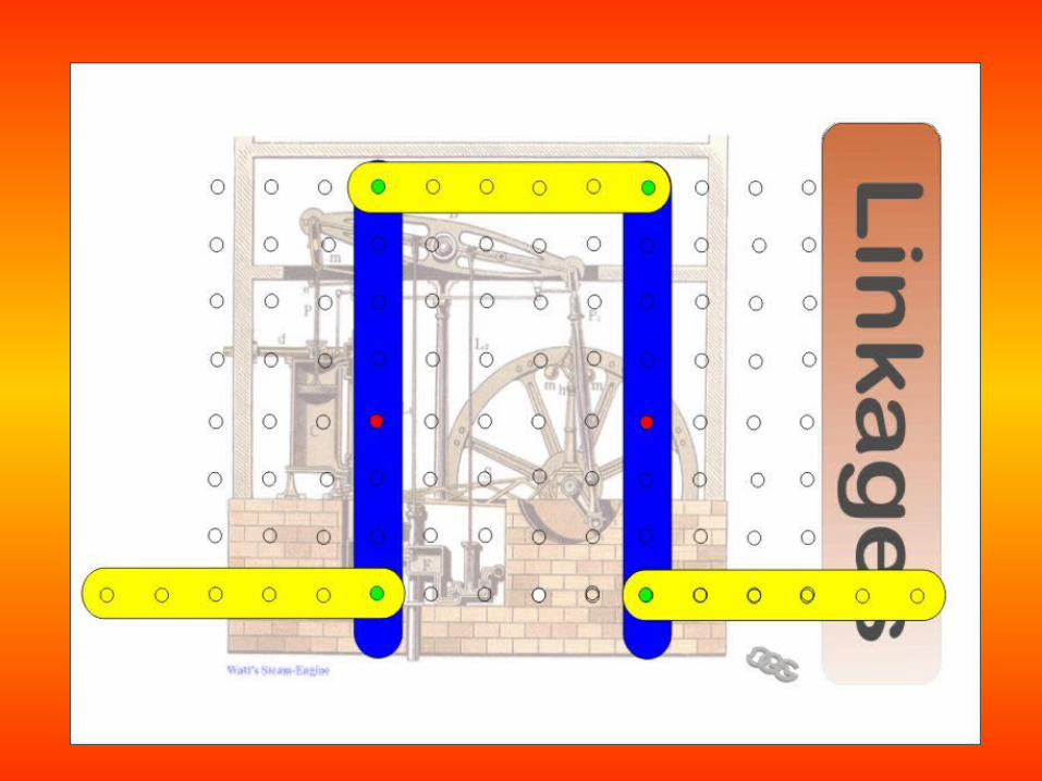
PARALLEL MOTION LINKAGE:
In 1784 Watt found a solution to his engine problems (which he
called "parallel motion") that was
developed in several different
configurations.

CRANK AND SLIDER LINKAGE:
The rods move forwards and
backwards in slider. The fixed pivot anchor
the linkages to one place.

CRANK AND SLIDER LINKAGE:
The crank which is the rotating disc, the slider which slides inside the tube and the connecting rod which joins the
parts together. As the slider moves to the right the
connecting rod pushes the wheel round for the first 180 degrees of wheel rotation. When the slider begins to
move back into the tube, the connecting rod pulls the
wheel round to complete the rotation.

BELL CRANK LINKAGE:
This linkage allows horizontal movement
to be converted to vertical movement. It
also works the opposite way round. A practical example of
this is the brake mechanism on a
bicycle.


BELL CRANK LINKAGE:
BICYCLE BRAKES: Look at the diagram carefully. As the
brake lever on the bike is pulled the cable moves
upwards and forces the brake blocks against the rim of the wheel. Explain the type of
linkage involved - using notes and diagrams. Look at the page 'linkages' to help you
decide.

BELL CRANK LINKAGE:
From the SafeAir1 glider wing pushrod on the
aileron.
Clear use of a bell crank

Windscreen Wipers

Design a linkage to solve this problem – You cannot cross the wall

One Answer


Free Linkage Software
http://www.edu-ctr.pref.kanagawa.jp/LinkWeb/index_e.htm